

Page 1
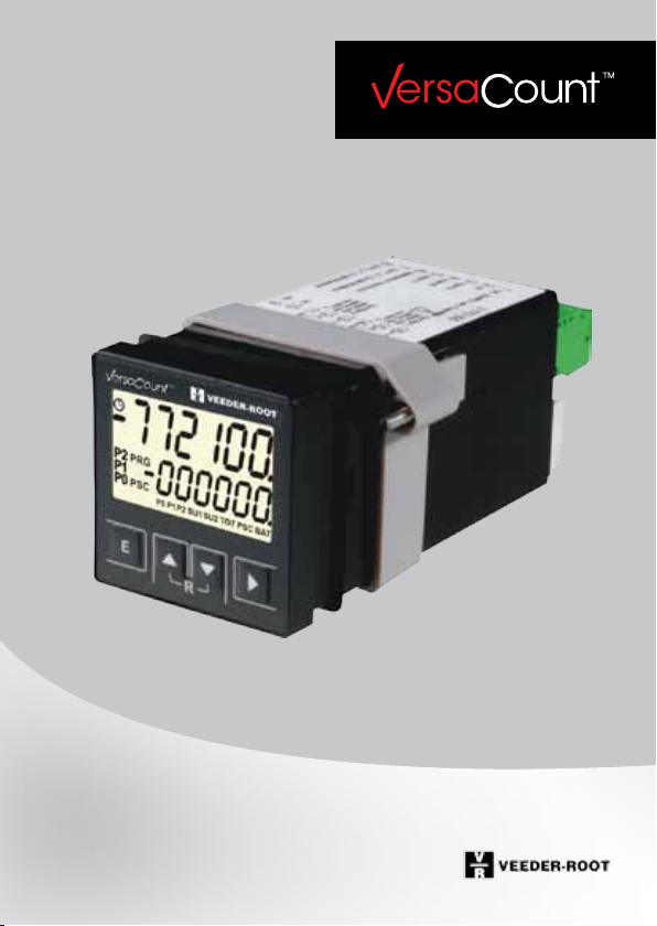
User Manual
bidirectional
Multifunctional-Counter
Part-No. 2 772 058 englisch; 05/2011
Page 2

Page 3

Table of Contents
1 General Information 6
1.1 Information about the Operating Instructions 6
1.2 Explanation of symbols 7
1.3 Limitation of Liability 8
1.4 Copyright protection 9
1.5 Guarantee conditions 9
1.6 Customer Service 11
2 Safety 10
2.1 Intended Use (Proper Use) 10
2.2 Assembly, connecting, programming 11
2.3 Responsibilities of the machine/plant manufacturer
and operator 13
2.4 Staff-related requirements 14
2.5 Special hazards 15
2.6 Safety devices 16
3 Setup and Operation 17
3.1 Dimension Sheet / Multifunction Counter Installation 18
3.2 Connecting the Multifunction Counter 18
3.3 Display 20
3.4 Keyboard functions 21
3.5 Overview of Operating Elements 23
3.6 Programming the Standard Function 24
3.7 Programming the Function Codes 25
3.8 Programming the Preset Modes 26
3.9 Prescaler Programming 28
3.10 Programming the (User) Times 29
3.11 Output of ID Data 30
3.12 Adjusting the intensity of the backlight 31
III
Page 4

Table of Contents
4 General Description of Multifunctional Counter 32
5 Pulse Counter 37
5.1 Description of Pulse Counter 37
5.2 Signal diagrams – counter input signals 38
5.3 Signal diagrams – counter output signals 40
5.4 Programming the counter function codes 42
6 Tachometer 54
6.1 Tachometer description 54
6.2 Signal diagrams - tachometer 55
6.3 Programming the tachometer function codes 56
7 Timer 65
7.1 Timer description 65
7.2 Signal diagram – timer input signals 67
7.3 Signal diagrams – timer output signals 68
7.4 Programming the timer function codes 69
8 Shift Counter 82
8.1 Shift counter description 82
8.2 Scroll between Total Sum and Partial Sums 83
8.3 Signal diagrams – shift counter input signals 83
8.4 Signal diagrams – shift counter output signals 84
8.5 Programming the shift-counter function codes 85
9 Batch Counter 96
9.1 Batch counter description 96
9.2 Signal diagrams – batch counter 97
9.3 Programming the batch counter function codes 97
IV
Page 5

Table of Contents
10 Technical Data 110
11 Transport, Packaging, Storage 117
12 Maintenance and cleaning 117
13 Malfunctions 118
14 Spare Parts 120
15 Dismantling and Disposal 120
16 Ordering Information 121
17 Accessories and spare parts 122
18 Supplementary information
relating to the users‘ manual 124
V
Page 6

General Information
1 General Information
1.1 Information about the Operating Instructions
These operating instructions provide important information about the handling of the multifunctional counter. To ensure safe operation it is vital that the
safety information and instructions be strictly observed.
For Counters with interfaces VersaCount 773 and VersaCount 774 please see
attached the amendment „Supplementary information relating to the users‘
manual“ (page 123)
The multifunctional counter has been designed for industrial use and for installation in machinery or industrial plants.
The manufacturer of the machine/plant in which the multifunctional counter
is used has to ensure that the function of the counter is properly described in
the Operating Instructions of the machine or plant, and that the description is
in accordance with manufacturer’s programming functions.
The manufacturer’s safety rules shall be applicable.
In addition, the local regulations concerning the prevention of accidents and
general safety information applicable to the machinery/plant shall be adhered
to.
Before starting any work on the machine/plant, the operating instructions and
in particular, the Safety chapter and the respective safety information must be
fully read.
These operating instructions are an integral part of the product and must be
maintained in the direct vicinity of the machine/plant and in a place that is
readily accessible for the operating staff.
These operating instructions contain important information concerning the installation, connection and programming of the multifunctional counter.
6
Page 7
General Information
Description of the programming sequence:
- Programming of the basic functions
- Programming of the function codes
- Programming of the user times
- Programming of the prescaler
- Programming of the presettings
Before starting to run the machine/plant, all functions that are not allowed to
be changed by the operator have to be blocked.
The executed programming functions have
to be documented.
1.2 Explanation of symbols
The warnings in these operating instructions are designated by symbols. Signal
words at the beginning of the warnings indicate the severity of a safety hazard.
These notes have to be observed by all means, and all actions have to be taken
with utmost care so as to prevent any accidents or damage or personal injury.
Danger!
This warning indicates a direct safety hazard,
which may lead to serious injuries or even death
if preventative action is not taken.
Warning!
This warning indicates a possible safety hazard,
which may lead to serious injuries or even death
if preventative action is not taken.
7
Page 8
General Information
Caution!
This warning indicates a possible safety hazard,
which may lead to minor damage or injuries if
preventative action is not taken.
Note!
This symbol indicates a potentially hazardous
situation, which may lead to damage to property
or to the environment if preventative action is not
taken.
Tips and recommendations
This symbol is used to point out to useful tips and
recommendations and information ensuring efficient and trouble-free operation.
1.3 Limitation of Liability
The information and notes contained in these operating instructions were
gathered in accordance with the applicable standards and regulations, the
state-of-the-art, as well our long-standing experience and know-how.
The manufacturer shall not assume any liability for damage caused by:
- Non-adherence to the operating instructions
- Improper use
- Employment of unskilled or untrained personnel
- Makeshift changes or manipulation
- Opening of the multifunctional counter
As a result of special design versions, special ordering options or the latest
technical developments, the actual scope of delivery may deviate from the
scope described and illustrated here.
8
Page 9
General Information
1.4 Copyright protection
The operating instructions must be treated confidentially and used exclusively
by the personnel responsible for the setup, maintenance, repair and operation
of the machine/plant. Disclosure of these operating instructions to any third
parties shall not be permissible without the prior written consent of the manufacturer.
The data and information stated here, including
text, drawings, images and other illustrations, are
protected by copyrights and subject to industrial
property rights. Any misuse of such information
shall be subject to prosecution.
1.5 Guarantee conditions
Our standard warranty is available on our website at
www.veeder-rootcounters.com.
1.6 Customer Service
Our customer service is available to provide technical information and assistance for our customers. Detailed information on your responsible contact
partner is given on our homepage (www.veeder-rootcounters.com).
9
Page 10

Safety
2 Safety
This section provides an overview of all the important safety-relevant aspects
to ensure best possible protection of the operating personnel as well as safe
and trouble-free operation. Non-adherence to the instructions given in this
manual may result in considerable safety hazards.
2.1 Intended Use (Proper Use)
The multifunctional counter is exclusively designed and constructed for the
intended use and purposes described here.
The multifunctional counter serves together with a corresponding sensor
for the counting of piece numbers, lengths, flow rates, velocities and
times, as well as for the controlling and monitoring of machinery and
equipment by sending control signals.
Warning!
Safety hazards due to improper use / misuse!
Using the multifunctional counter for any purposes
other than the ones described within the scope of
intended use may cause hazardous situations. Claims
for damages resulting from any kind of misuse
shall be expressly excluded.
10
Page 11

Safety
2.2 Assembly, connection, programming
These multifunctional counters are built and tested in accordance with IEC/EN
61010-1, Protection Class II – Safety Measures for Electronic Measuring
Equipment. They have left the factory in a condition that is in compliance with
all safety-relevant requirements. In order to maintain this condition and ensure operational safety, the User is requested to observe the safety notes and
warnings given in these operating instructions!
Danger!
Risk of safety hazards due to incorrect/faulty assembly and connection.
• Themax.operatingvoltagesmustnotbeexceeded!
• 12–24VDCand24VACmultifunctionalcountershavetobeoperatedat
safety extra-low voltages (SELV) and under potential-compensated conditions in order to prevent hazardous shock currents.
• Anexternalfusehastobeprovidedtoprotectthemultifunctionalcounter
(see Chapter 10, Technical Data).
• Installationandassemblyshallbecarriedoutbyskilledandtrainedelectricians only.
• Donotconnectthemultifunctionalcounterwithoutmakingsurethatitno
longer carries any live voltages. Always separate it from the mains supply
before connecting.
• Makesurethatliveterminalsareproperlyprotectedagainstinadvertent
contact.
• Toensureproperprotectionofterminalsagainsthandcontact,makesure
that the live conductors are properly connected to the terminals.
• It‘snotallowedtousethemultifunctionalcounteroutsideofthespecified
temperature range. If neccessary appropriate precoutions have to be applied
11
Page 12

Safety
(e.g.airventilation).•Therulesandregulationssetforthbythelocalelectricity providers have to be observed.
• Donotestablishanyconnectionswithnon-allocated(NC)terminals.
• Multifunctioncountersmayonlybeoperatedinaproperlyinstalledcondi-
tion.
• Ifsafeoperationseemstobeimpaired,makethemultifunctionalcounter
inoperable and secure it against inadvertent operation.
• Scopeofapplications:industrialprocessesandcontrols.Overvoltageacross
the terminals must be limited to the values of overvoltage category II.
• Theinstallationandwiringenvironmenthasconsiderableimpactonthe
electromagnetic compatibility of the multifunctional counter. Therefore,
electromagnetic compatibility of the entire plant has to be ensured during
the installation.
• InareaspresentingtheriskofESD(electrostaticdischarge),makesureto
use ESD-protected plugs and switches during the installation.
• Ifthefunctions“prescalerinput”,“presetinput”and“keyreset”arenotallowed to be used by the machine/plant operator, access to these functions
must be blocked for machine operators. Depending on the machine/plant
design or concept, non-permissible input may impair the operational safety
and function of the machine or plant.
Danger!
The manufacturer of the machines / plants has to
ensure, that no risks result from this.
• Themachine/plantmanufacturershallberesponsibleforthepreparationof
operating instructions / plant description including the following:
12
Page 13

Safety
•Descriptionoffunctionsaccordingtotheprogrammingofthemultifunction counter;
•Descriptionofthesettingstobeadjustedbythemachine/plantoperator;
•Informationconcerningtheoccupationalsafetyrequirementsandpossi-
ble hazards arising from the operation of the machine/plant.
2.3 Responsibilities of the machine/plant manufacturer
and operator
Multifunctional counters are designed for installation in machines/plants.
Therefore, the manufacturer and
operator of the machine/plant are subject to the legal obligations concerning occupational safety and health.
Besides the safety notes given in these operating instructions, the relevant
rules and regulations concerning safety and the prevention of accidents,
and the applicable environmental requirements have to be met. In particular:
• Themachine/plantmanufacturershallbeobligatedtoensurethatallthe
requirements mentioned in section 2.2 be fulfilled during the assembly,
connection and programming.
• Theoperatorshallobtainalltherequiredinformationabouttheapplicable
occupational safety rules. In addition, the operator shall be obligated to
prepare a risk assessment of possible hazards that may arise due to the special working conditions at the place of installation of the machine/plant.
This risk assessment shall be documented in the form of operating instructions for the machine/plant.
• Throughouttheentireoperatingtimeofthemachine/planttheoperator
shall be obligated to check if the operating instructions prepared are in accordance with the latest status of requirements and, if required, make the
appropriate adjustments.
13
Page 14

Safety
• Theoperatorshallensurethatallstaffmemberswhoareinvolvedinthe
machine/plant operation have read and fully understood these instructions.
Moreover, the operator shall be obligated to train the operating personnel
at regular intervals and inform them about any potential hazards.
• Theoperatorshallensurethattheoperationandcleaningofthemachine/
plant is exclusively carried out by skilled and trained personnel.
• Theoperatorshallensurethatallmaintenanceandrepairworkshallonly
be carried out by skilled and trained personnel.
2.4 Staff-related requirements
Warning:
Danger of personal injuries if handled by insufficiently qualified staff! Improper handling may cause
severe personal injuries and damage to property.
• Actionsrequiringspecialskillshavetobecarriedoutonlybythepersonnel
designated in the appropriate sections of these instructions.
• Keepunqualifiedpersonnelawayfromhazardareas.
The following staff qualification requirements have been
defined for the various scopes of activities:
• Instructed personnel
These persons have been instructed by the operator with regard to the tasks
assigned and the potential hazards caused by improper handling.
• Skilled personnel
Due to their educational and professional skills, know-how and experience,
as well as due to their knowledge of the relevant regulations, these persons
are capable of executing their assigned tasks and recognize potential hazards independently.
14
Page 15

Safety
• Skilled and trained electricians
Due to their educational and professional skills, know-how and experience,
and due to their knowledge of the relevant regulations in the field of electrical engineering, these persons are capable of executing electrical work
and recognizing potential hazards independently.
2.5 Special hazards
This section indicates certain residual risks, which may arise as a result of the
risk assessment.
The safety information and warnings given here and in the following chapters
of these instructions have to be observed in order to reduce any health hazards and avoid hazardous situations.
Electric current
Danger!
Lethal hazard of electric shock!
Any contact with hazardous live components presents a direct lethal hazard.
Damages of the insulation or individual components present a potential lethal hazard.
• Intheeventofanydamagetotheinsulation,immediately disconnect the voltage supply and initiate the
appropriate repair work.
• Anyworkontheelectricalplanthastobecarriedout
by skilled and trained electricians only.
• Beforecommencingyourworkontheelectricalsystem,
disconnect it from the main supply and check that it
no longer carries any live voltages.
15
Page 16

Safety
• Priortoconductinganymaintenance,cleaningorrepair
work, disconnect the mains supply and secure it against
inadvertent switching on.
• Donotshort-circuitormakefusesinoperable.
2.6 Safety devices
Warning! Lethal hazard by non-functional safety
devices! Safety devices are provided to ensure a
maximum of operational safety.
The multifunctional counter itself does not include any installed safety devices.
These safety devices have to be attached externally.
Protect the electrical supply of the multifunctional counter by means of external fuses (see Chapter 10, Technical Data).
Whether or not additional safety devices (e.g. emergency-off buttons) have to
be provided depends on the general design and construction of the machine or
plant.
The machine/plant manufacturer shall be responsible for providing such additional safety devices in according with his own risk assessment.
16
Page 17
Safety
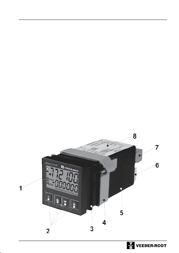
3 Setup and Operation
1 Display
2 Operating keys
3 Flat gasket
4 Bracket
5 Enclosure
6 Plug for DC or sensor supply;
Electronic inputs and outputs
7 Connection terminal AC supply and relay contacts
8 Circuit diagram
17
Page 18
Safety
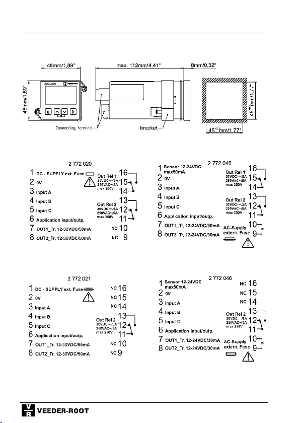
3.1 Dimension Sheet /
Installation of Multifunction Counter
3.2 Connecting the Multifunctional Counter
VDC 2 relays / 2 transistors VAC Trafo 2 relays / 2 transistors
VDC 1 relay / 2 transistors VAC transformer 1 relay / 2 transistors
18
Page 19
Setup and Operation
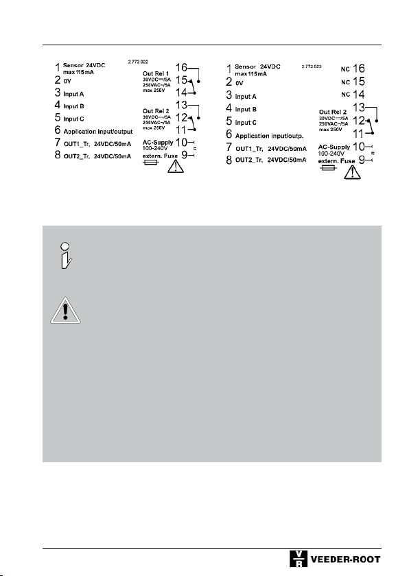
VAC switching power supply VAC switching power supply
2 relays / 2 transistors 1 relay / 2 transistors
The plug has to be disconnected from the counter
before the cables are fastened by means of screws
or screw-type terminals.
It is not allowed to contact the encoder to a direct
current line voltage without protective circuit for
EMC. For cable lengths > 30 m a protective circuit
is always necessary!
When programming the input level to TTL an additional protective circuit is necessary.
We recommend the installation in an metallic
environment.
19
Page 20
Setup and Operation
Only valid for DC-Versions:
When switching on the device in PNP-Mode, a short signal is applied to inputs
A,B,C and the application input.
To suppress the pulse in TTL-Mode each input has to be connected to a resistor of 10 kOhm/0,125W against 0V.
When switching on the device a short signal is applied to the application output.
This pulse, if needed, is possible to suppress by connecting a resistor of 10
kOhm / 0,225 W against 0 V to the application-output.
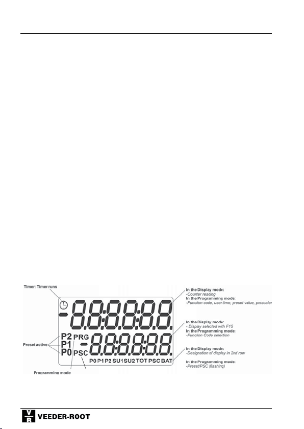
3.3 Display
After switching on, all segments and characters are illuminated for approx. 2
seconds; then the display changes over to the Display or Programming Mode.
The display is available in five different versions:
Reflectiv: black figures on bright reflecting background
Transflective positive: black figures on back lighted ground
Transmissive white: white figures on black ground
Transmissive red: red figures on black ground
Transmissive green: green figures on black ground
Prescaler
20
Page 21
Setup and Operation
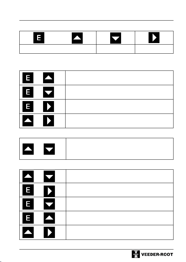
During the Programming of Function Codes
Enter - Key UP - Key Down - Key SHIFT - Key
Programming
If pressed together with POWER ON (keep keys pressed and switch on the device)
+
+
+
+
Selects standard functions
Sets function codes
Selects ID data
(Article code (ID No.), manufacturing date, serial number,...)
Sets User Times
During the Programming of Function Codes
Display of function code
+
Switches between function code text and function code
number
During Operation
+
+
+
+
+
Reset
Sets preset 0
Sets preset 1
Sets preset 2
Sets prescaler
21
Page 22
Setup and Operation
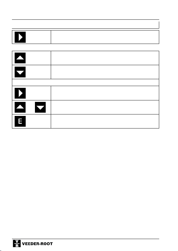
Additional function for shift and batch counters
Switches between total sum and partial sums and/or
count value and totalizer or batch counter
Additional function for timers
Timer start
(If enabled with function code F15)
Timer stop
(If enabled with function code F15)
Additional function backlight versions
Go to the adjustment menu
(pressing > 5 s)
+
Adjustment of the intensity
(brighter or darker)
Save and going back to display mode
(Pressing within 15 s)
22
Page 23
Setup and Operation
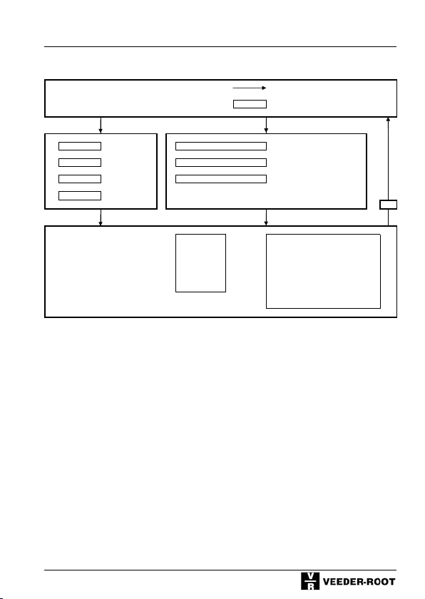
3.5 Overview of Operating Elements
Display Mode Reset
up + shift = Prescaler
123456 up + dn 0
E + up at power on
E + dn at power on
up + shift at power on
semit langiS = 0 teserP = tfihs + E
Programming Mode Standard Funct. Function parameters:
Pulse counter Operat. Mode Count frequency
Tachometer Decimal point Reset Behavior
Shift counter Display-Mode Keylock
Batch counter Output signals npn/pnp selection
Applic. Input/Output
+ many other function parameters
noitcnuf dradnatS = 2 teserP = pu + E
retemaraP noitcnuF = 1 teserP = nd + E
E
yromeM tuptuOedoM-teseR/teSremiT
23
Page 24
Setup and Operation
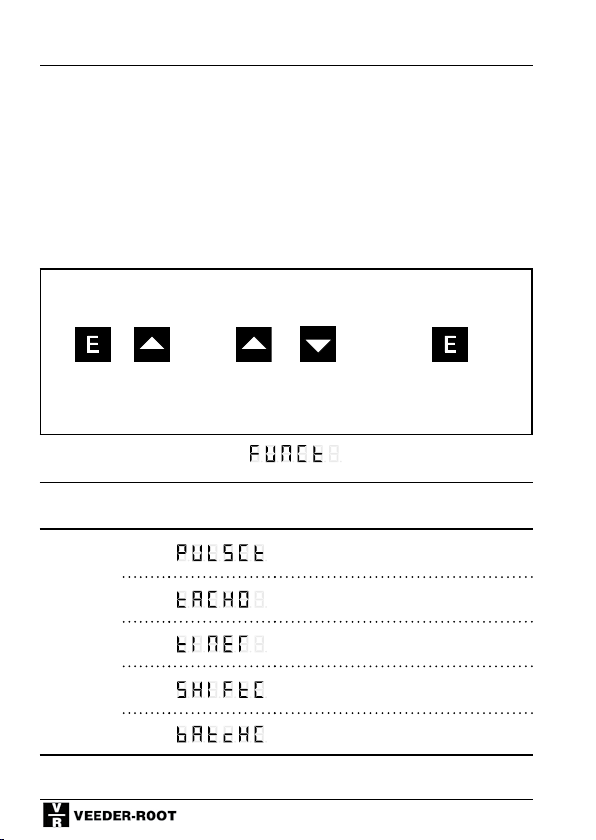
3.6 Programming the Standard Function
The device described here is a multifunctional counter, which can be programmed for a variety of functions, i.e. pulse counter, tachometer, timer, shift
counter or batch counter functions. The first step is to set the standard func-
tion(thefactorysettingofthedeviceisthe“pulsecounter”setting).
Now continue with the programming of the function codes (Chapters 5-9) or
User Times (Chapter 3.10)
Programming mode Change function
+ or
Keep pressed and
switch voltage on
simultaneously
Function code Fn, Display Row 1
Function No.
Setting of
Standard
Function
0*
1
2
3
4
Display
Row 2
setting:
operation
press press
Pulse counter
Tachometer
Timer
Shift Counter
Batch Counter
24
Save, return to counter
Page 25
Setup and Operation
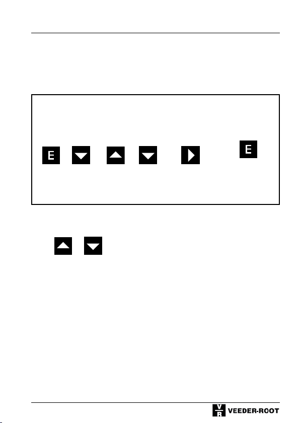
3.7 Programming the Function Codes
The function codes (system parameters) are used to program the function and
behavior of the inputs and outputs, as well as the behavior of the device in its
adjusted basic mode. The detailed selection options are described in Chapters
5 to 9.
Programming
mode
Change function
setting
Save and
change to
next function
code
Save and change
to counter
operation
+ or
Keep pressed and
switch voltage on
simultaneously
press press press
Change between Text Display and Numerical Display
In the function code Programming Mode, the first row shows the name of the
function code in the form of text (7-segment display). The second row shows
the selectable option in a text form, too. By simultaneously pressing the Up
and Down buttons, the display in the first row changes to a numerical display;
after pressing these buttons once again, the display in the second row also
changes to a numerical display. Pressing these buttons for a third time reverts
both rows to the text display again.
+
25
Page 26

Setup and Operation
Attention: With each change among text and
numeric display, the currently activated function
code will return to the factory setting and may
have to be readjusted.
The factory setting is designated with an asterix *.
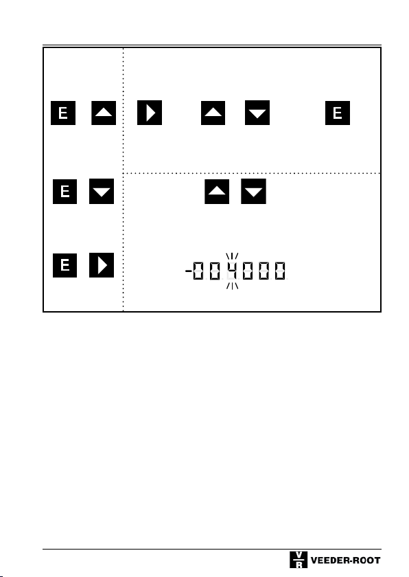
3.8 Programming the Preset Values
By simultaneously pressing the E + Up, E + Down or E + Shift key you can
change to the Preset programming mode:
Use the shift key in the programming mode to change a setting position. The
selected position will start to flash. Use the shift key again to move by one position to the right. Then use the UP or Down key to increment or decrement
the position by 1.
Rule for the 6th position: The change from 9 to 0 or 0 to 9 is indicated by a
changing prefix.
Use the E key to leave the programming mode and return to the display mode.
Your entries will be saved.
On leaving the programming mode, the presets are tested for attainability and
recalculated, if necessary, because not all the values may be attained at a
prescaler value of >1. The presetting is then rounded to the next attainable
value.
If no key is pressed for more than 16 seconds in the programming mode, the
counter will automatically return to the display mode. In this case, however,
no entries will be saved except the last value saved with the E-key.
Set the preset value to 0 by pressing Up and Down keys simultaneously.
26
Page 27
Setup and Operation
Programming
mode
+ or
Preset 2 press press press
+ +
Preset 1
+
Preset 0
Position
flashes:
Set position: Save and return
display mode
to
Zero in
Set Preset
27
Page 28
Setup and Operation
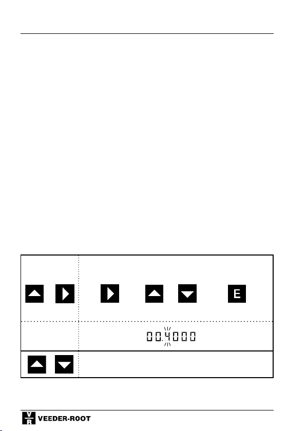
3.9 Prescaler programming
By pressing the Up + Shift keys simultaneously you can change to the Prescaler Programming Mode.
In the Programming mode, the position to be changed is selected by means of
the shift key. The selected position will start flashing. Use the shift key again
to move by one position to the right. Then use the UP or Down key to increment or decrement the position by 1. It is not possible to save a value of
00,0000. In this case the system will save 01,0000.
Use the E key to leave the programming mode and return to the display mode.
Your entries will be saved.
On leaving the programming mode, all the presets are recalculated because
not all the values may be attained with a prescaler value of >1. Therefore, the
presets have to be checked and corrected as necessary after saving the prescaler.
If no key is pressed for more than 16 seconds in the programming mode, the
counter will automatically return to the display mode. In this case, however,
no entries will be saved except the last value saved with the E-key.
Press the Up and Down keys simultaneously to set the prescaler to 01,0000.
Programming
mode
select a position:
(starts flashing)
Set position Save and return to
+ or
press press press press
set to 01,0000
+
28
display mode
Set prescaler
Page 29
Setup and Operation
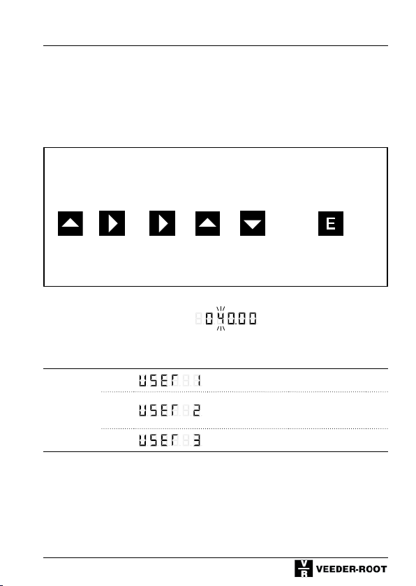
3.10 Programming the user times
For programming the signal time for monostable output signals, 9 fixed signal
times between 0.02 s and 10 s are available. In addition, three different signal
times between 0,01s and 599,99s can be set by the user. The outputs are
deactivated if the setting is 0.00 s.
Programming
mode
Select a
position
+ or
Keep pressed and
switch voltage on
simultaneously
Function code Fn, Display-Row 1
Function No.
Sets the
Signal
Times
0*
1
2
press press press
Display
Row 2
Set position Save and go to the
next user setting; after
user 3, return to dis-
play mode
Signal time 1
Signal time 2
Signal time 3
29
Page 30
Setup and Operation
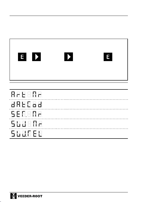
3.11 Output of ID data
This function is used to retrieve ID data, e.g. article numbers and various manufacturing data.
Output mode Change to the next
output
+
Keep pressed and
switch voltage on
simultaneously
Display row 1 Display row 2
press press
Article number
Manufacturing date
Serial number
Software number
Software release
Return to counter ope-
ration
30
Page 31

Setup and Operation
3.12 Adjusting the intensity of the backlight
For counters that come with a backlight you have the possibility to adjust the
intensity of their backlight.
To get into the menu of the adjustment, you have to press SHIFT for more than
5 seconds. The display then shows:
By pressing the UP or DOWN key the display gets brighter or darker.
If the E-button is pressed within 15 s, you go back to the normal counter display and the adjusted setting is saved. If the E-button is not pressed within 15
seconds, you will go back automatically to the normal counter menu without
saving any made changes.
Go to the adjustment
menu
Adjustment of the in-
tensity
Save and going back to
display mode
or
pressing > 5 s press Pressing within 15 s
31
Page 32

General description of multifunctional counter
4 General description of multifunctional counter
The following description is applicable for all standard settings. Special descriptions can be found in the appropriate chapters of this manual.
Factory setting
(Defaults)
Sets all the function codes to the factory settings, i.e. all codes designated
with *.
Prescaler (pulse metering factor):
The“Prescaler”isamultiplier.Eachinputpulseismultipliedbytheadjusted
factor. The display shows integers only. After a reset the counter is completely
reset to 0; this also includes the non-visible value of < 1.
At a prescaler of >1 not all the values are selectable. If invalid Preset values
are selected, the counter will round them up to the next possible value.
Example: PSC 5 cannot select (reach) Preset value 7. In this case, the counter
automatically changes the Preset value to 10).
If the Prescaler is changed, this may also affect the Preset values, which may
have to be changed accordingly.
Adjusting range 0,0001 to 99,9999
The Prescaler is used, for example, to convert counter pulses into meaningful
units, to adapt the units of measurements (e.g. cm-pulses to inch-pulses), or
to compensate for worn out measuring wheels.
Formula: PSC = Desired/nominal display / number of pulses
Example: Flowmeter 173 pulses per 100 liters; display in liters
PSC = 100 / 173 = 0,5780
Example: 1 pulse per cm; display in inch
PSC = 1 / 2,54 = 0,3937
32
Page 33

General description of multifunctional counter
Attention: This is only valid for counters and tachometers.
For timers please refer to the special Timer Description.
Display 2. row:
The display of the 2nd row can be programmed as follows:
P 2, P 1, P 0, Prescaler, Batch counter, totalizer or partial sums
(shift counter)
Counter and control inputs:
The counter is fitted with 3 counter and control inputs and, in addition, with
an application input (see below). These inputs are assigned various counter or
control functions by means of function code settings
Input logic:
The input logic can be programmed to NPN or PNP, each at the 8V-level or TTL
level; see Technical Data for the switching threshold.
Reset/Set:
Manual setting via keys (lockable)
Electronic setting via control input (and/or application input)
Automatic programming after reaching the main Preselection
Programmable Power-On Reset
Depending on the function code the counter is:
1.) Reset: reset to 0
P 2 is the main Preset (preselect) value
During unidirectional counting the counter will add up.
or
2.) Set: reset to P 2
Signal 2 at 0
During unidirectional counting the counter will subtract.
For time counting, batch counting or shift counting, it is possible to reset partial sums or the total sum, batch counter or 2nd totalizer individually or at the
same time via the application input.
33
Page 34

General description of multifunctional counter
Independently the counter can be reset to Preset value 0 via the application
input (see below).
Exception: Tachometers do not have a reset/set function
Static/dynamic reset:
Static reset: Reset over the entire pulse width of the reset pulse
Dynamic reset: Reset via the active edge; thereafter, counter operation is
possible independently of the pulse width of the reset pulse.
Exception: Tachometers do not have a reset/set function
Teach input:
Using the Teach Input (application input) the counter status is imported in
Preset 2.
Decimal Point:
The decimal point is only an optical reading assistence on the display and does
not change the value. For example, for a value of 1 pulse per cm, the setting
0,00 makes it easier to read the value in m and cm.
Exception: This does not apply to tachometers and timers.
Please refer to the detailed Tachometer and Timer descriptions.
Input damping
(Attenuation)
The inputs A and B are limited to 60 kHz.
The Application Input is limited to 6 kHz.
Following maximum input frequencies are not to be exceeded:
Phasediscriminator single evaluation: A and B each 30 kHz (TTL 15 kHz)
Phasediscriminator double evaluation: A and B each 30 kHz (TTL 15 kHz)
Phasediscriminator quadruple evaluation: A and B each 15 kHz (TTL 15 kHz)
Unidirectional counting and directional input: Input A 60 kHz (TTL 15 kHz)
Differential counting, summation (totalizing): Input A + B 60 kHz (TTL 15 kHz)
34
Page 35

General description of multifunctional counter
When the application input is used as an additional count input, the above
mentioned input frequencies have to be reduced by the frequency of the application input:
If mechanical contacts are triggered (i.e. relays, switches, Reed contacts, etc.),
the input frequency has to be damped (attenuated) to 30 Hz, so as to filter out
bounce pulses.
If damping to 30 Hz is selected, all inputs can be used at 30 Hz.
To reach these values the amplitude thresholds are to be hold.
(See technical data - chapter 10)
Signal
P 1 and P 2 are available as relay changeover contacts and electronic output
signals (PNP).
P 0 is available as an electronic output signal across the application output
(PNP).
If a signal is active, this will be shown on the LCD display.
Optionally, the multifunctional counter can be set to have the display flash if
one or all the preset values are acive.
This is also valid for Preset 0 (if no output has been assigned)
Signaltime:
1.) bistable: Cleared by electronic or manual reset.
P 0 + P 1= bistable – additionally cleared by signal 2
Attention: Signal 2 must not be bistable for automatic reset.
2.) monostable: Up to 9 fixed signal times are available between 0,02s and
10s. In addition, user times can be programmed between 0,01s to 599,99s.
3.) Range signals: active as long as the counter reading is within the adjusted
range.
Signals active on/off
During normal operation the relay is energized if the signal is active.
This behavior can also be inverted (also applicable to the transistor outputs).
35
Page 36

General description of multifunctional counter
Application input/output:
Depending on the standard function, up to 11 (eleven) functions can be assigned to the application input/output. Note, however, that only one of these
functions can be selected.
Further details are given in the Function Code Chapter.
Application – Set to preset 0
Programs the application input to act as a Set Input. The counter is set to Preset 0, independently of the reset via input C or the keyboard.
This function is not available for tachometers.
Application keylock:
All keyboard functions can be locked (latched) individually
(Reset, P 0, P 1, P 2, Prescaler)
Lock mode: release after 10s, complete keylock or
keylock depending on keylock input (application input)
Our advice! After setting up the system, lock
(latch) all the keyboard functions that are not
allowed to be changed by the user.
36
Page 37

Pulse counter
5 Pulse Counter
5.1 Description of the Pulse Counter
(Supplementing the General Description in Chapter 4)
Counter mode:
The following counter modes can be selected:
Unidirectional counting, adding or subtracting;
Unidirectional counting with directional input;
Differential counting, summation (totalizing) or
phase discriminator (quad) with single, double or quadruple evaluation.
Output signals mode of operation:
1.) coincidence signal: The counter operates in the coincidence mode, i.e.
output signals are activated after reaching the Preset value for the programmed
period of time.
2.) Trail: P 2 and P 0 are under coincidence operation; they operate as described in item A.
P 1 is the trail. P 1 is not absolute to 0, but relative to P 2.
If the setting is F8=1, the following will apply:
Signal 1 is returned at P 2 – P 1
Example: P 2=1000, P 1=200, Signal 1 at 800;
If P 1 is negative: P 2=1000, P 1=(-200), Signal 1 at 1200
If the setting is F8=2, the following will be applicable:
Signal 1 is returned at P 2 + und – P 1
(Example: P 2=1000, P 1=200, Signal 1 at 800 or/and 1200)
3.) range signal: VW 1 and 2 are range signals:
Signal 1 is active at a counter reading < P 1 and
Signal 2 is active at a counter reading > P 2
Intermediate cut:
Depending on the application it may become necessary to isolate the main signal during the reset, e.g. when the first material lengths or certain lengths
showing material defects have to be cut on length-cutting systems.
37
Page 38

Pulse counter
Unidirectional counting (F1 = C G r) = 0
Additional totalizer (summation counter)
The additional totalizer sums up all values, even if the main counter is continually reset. The shift key can be used to switch between the counter reading
and the total sum. The totalizer can only be reset manually.
To do this, select the total sum from the first row; then press the reset keys.
Prescaler Output PSC-out:
The prescaler output is an application output.
With each increase of the counter reading the number of output pulses corresponds to the respective number of increments.
The pulse length of the prescaler output corresponds to a frequency of 500 Hz.
When using the prescaler output the max. count frequency is:
F max = 500 / PSC.
So it is possible that the maximum input frequency can not be reached.
Application counter input add / sub
The application input may be assigned to the Count Up or Count Down function.
This is a counter input, which is available in addition to the counter mode adjusted with F1.
Application Latch/Reset
Latch/Reset is an application input. If the counter is reset via the application
input, the counter reading is held constant. The counter continues to remain
fully functional and operates in the background mode. During the next reset
the current (updated) value will be shown on the display.
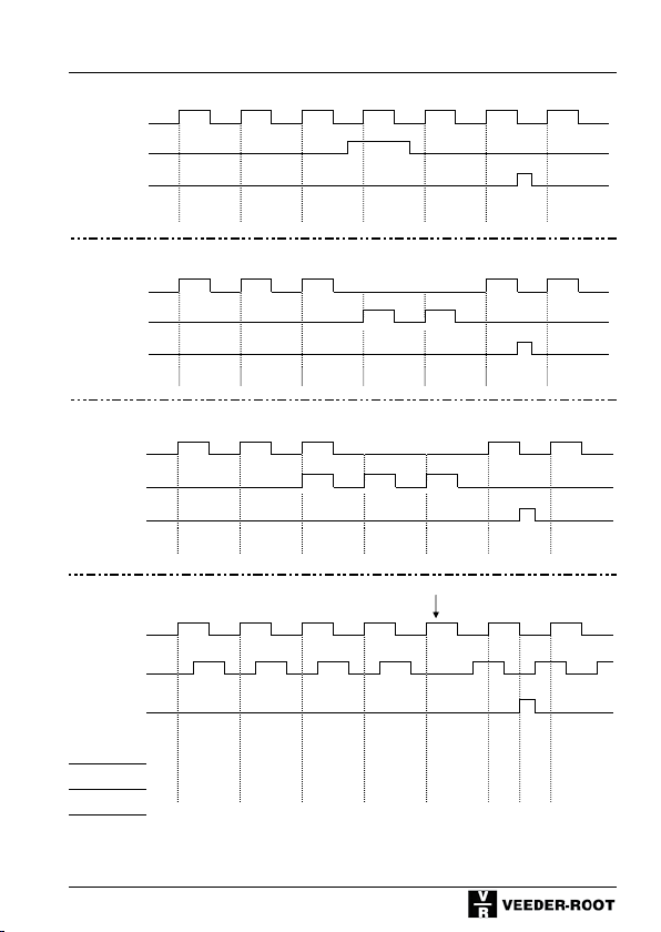
5.2 Signal diagrams input signals (PNP-Logic)
Input A
Counter input
Input B
Gate
Input C
Reset
Counter reading 1 2 3 3 4 5 0 1
38
Page 39
Pulse counter
Unidirectional counting (F1 = C G r) = 0
Input A
Counter input
Input B
Gate
Input C
Reset
Counter reading 1 2 3 3 4 5 0 1
Directional input(F1= C d r) = 1
Input A
Counter input
Input B
Directional input
Input C
Reset
Counter reading
Differential input (F1= A S r) = 3
Input A
Adding
Input B
Subtracting
Input C
Reset
Counter reading 1 2 3 2 1 2 0 1
Summation (totalizer) input (F1= A A r) = 5
Input A
Adding
Input B
Adding
Input C
Reset
Counter reading 1 2 4 5 6 7 0 1
Phase discriminator (F1 = QUAd r) = 6 Change of rotating direction
Channel A
Channel B
1 2 3 2 3 4 0 1
Input C
Reset (dynamic)
Counter reading single 1 2 3 4 5 4 0 -1
Evaluat. (F2=0)
Counter reading double 1 2 3 4 5 6 7 8 9 8 7 0 -1 -2
Evaluat. (F2=1)
Counter reading quad. 1 2 3 4 5 6 7 8 9 10 11 12 13 14 15 16 17 17 16 15 14 13 0 -1 -2 -3 -4
Evaluat. (F2=2)
39
Page 40
Pulse counter
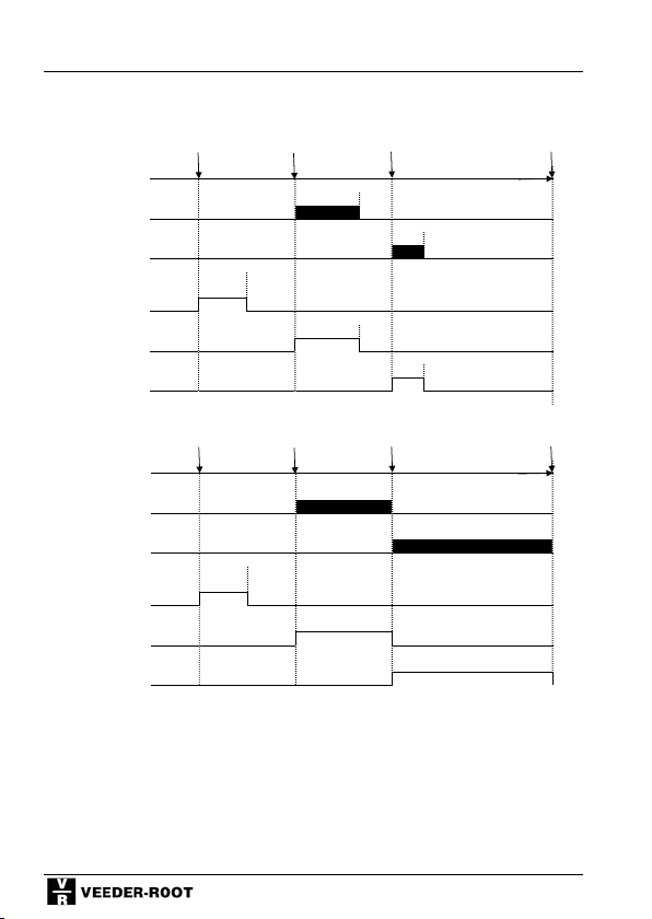
5.3 Signal diagrams - Output signals
Output signals monostable
Coincidence signals P 0 (F10), P 1 (F11), P 2 (F12) monostable
Counter reading
P 1 (Relay)
P 2 (Relay)
P 0 electronic time
(Application output)
P 1 electronic
P 2 electronic
Output signals bistable
Coincidence signal time P 0 (F10) monostable P 1 (F11), P 2 (F12) bistable
Counter reading
P 1 (Relay)
P 2 (Relay)
P 0 electronic time
(Application output)
P 1 electronic
P 2 electronic
Signal
Preset 0 Preset 1 Preset 2 Reset
Signal
Signal time
Signal time
bistable
bistable
Signal
time
Signal
time
teseR Preset 0 Preset 1 Preset 2
bistable
bistable
40
Page 41
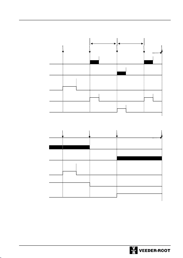
Trail Preset
P 0 (F10) Coincidence signal monostable, P 1 (F8+F11) trail signal, symmetrical,
P 2 (F12) Coincidence signal monostable
P 2 - P 1 P 2 + P 1
Counter reading
P 1 (Relay)
P 2 (Relay)
P 0 electronic
(Application output)
P 1 electronic
P 2 electronic
Range signals
P 0 (F10) Coincidence signal monostable P 1 + P 2 range signal
Counter reading
P 1 (Relay)
P 2 (Relay)
P 0 electronc
(Application output)
P 1 electronic
Preset 0 Preset 2 Reset
Signal
time
Signal
time
Signal
time
Signal
time
Signal
time
Preset 0 Preset 1 Preset 2 Reset
Signal
time
Pulse counter
Signal
time
Signal
time
P 2 electronic
41
Page 42
Pulse counter
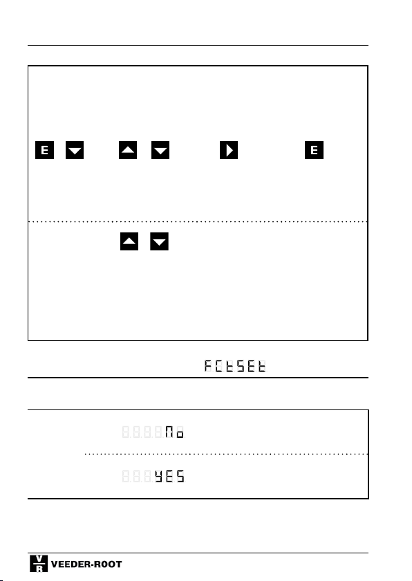
5.4 Programming the counter function codes
Program-
ming mode
+ or
Keep pressed
and
simultaneously
turn Voltage On
Alternative
display
of function
codes
Change
function
setting
press press press
+
Function code F0, Display Row 1:
Function No.
Factory
Setting
(Defaults)
Display
Row 2
0*
1
Save and
change to
next func-
tion
The function codes are displayed as
text in row 1.
By pressing both keys simultaneously you can change to the numerical display (F 0 to F 35). After
pressing these keys once again the
number of the selectable options
will be displayed in addition. This
setting will be stored.
No Function
All Function Codes are set to
the values marked with *
Return to display
mode
42
Page 43
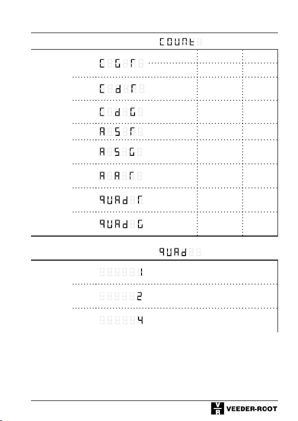
Function code F1, Display Row 1:
Counter
Mode
0*
1
2
3
Pulse counter
Input A Input B Input C
Count. inpt. Gate Reset
Count.inpt.
Count.inpt.
Adding Subtracting Reset
Direction.
Input
Direction.
Input
Reset
Gate
4
5
6
7
Adding Subtracting Gate
Adding Adding Reset
Channel A Channel B Reset
Channel A Channel B Gate
Function code F2, Display Row 1:
0*
Edge
Evaluation
/Quadrat.
1
evaluation
2
Single evaluation
Double evaluation
Quadruple evaluation
43
Page 44
Pulse counter
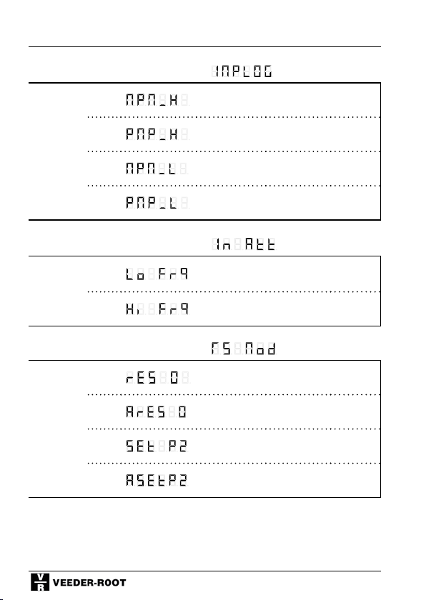
Function code F3, Display Row 1:
PNP/NPNLogic
0
NPN-8V-Level
1*
2
3
Function code F4, Display Row 1:
Inputdamping
(Attenuation)
0
1*
Function code F5, Display Row 1:
Set / Reset- Mode
0*
1
2
3
PNP 8-V Level
NPN TTL-Level
PNP TTL-Level
30 Hz damping (e.g. for mechanical
contacts)
F max. (see chapter 4 and 10)
Reset to 0
Automatic reset to 0 after reaching
Preset 2
Set to Preset 2
Automatic set to Preset 2 after
reaching 0
44
Page 45
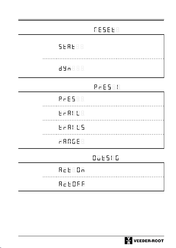
Function code F6, Display Row 1:
dynam./
static
Reset
0*
Pulse counter
Static reset (reset as long as the signal
is applied)
1
Function code F8, Display Row 1:
Mode
Preset 1
0*
1
2
3
Function code F9, Display Row 1:
Output
signal
o*
1
Dynamic Reset (ready to count after
reset (even if reset signal is applied for
a longer time)
P 1 normal preset; absolute to the
counter reading (coincidence signal)
P 1 as a trail preset with prefix
(relative to P 2)
P 1 as a trail preset symmetric trail
(relative to P 2)
P 1 and P 2 as a range signal
(Sign.1 < P 1, Sign.2 > P 2)
Active On
Active Off
45
Page 46
Pulse counter
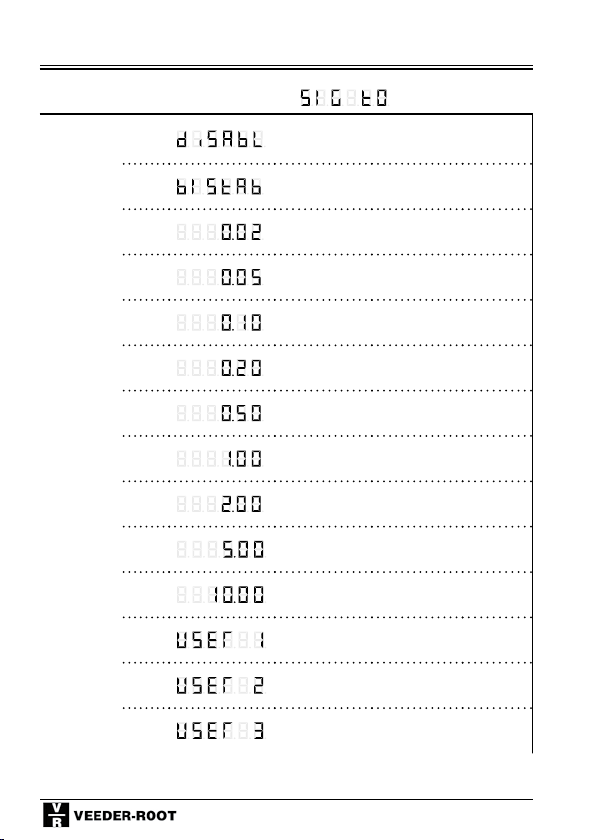
Function code F10, Display Row 1:
Signal
time P 0
0
Disabled / No output signal
1
2
3
4*
5
6
7
8
9
10
11
12
13
Bistable, reset with Preset 2 or Reset
0,02 s
0,05 s
0,10 s
0,20 s
0,50 s
1,00 s
2,00 s
5,00 s
10,00 s
User setting 1 (0-599,99 s)
User setting 2 (0-599,99 s)
User setting 3 (0-599,99 s)
46
Page 47
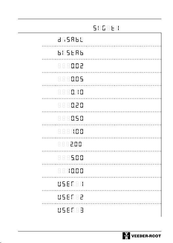
Function code F11, Display Row 1:
Signal
time P 1
0
Disabled / No output signal
Pulse counter
1
2
3
4*
5
6
7
8
9
10
11
12
13
Bistable; Reset with Preset 2 or Reset
0,02 s
0,05 s
0,10 s
0,20 s
0,50 s
1,00 s
2,00 s
5,00 s
10,00 s
User setting 1 (0-599,99 s)
User setting 2 (0-599,99 s)
User setting 3 (0-599,99 s)
47
Page 48
Pulse counter
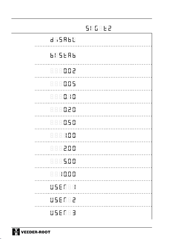
Function code F12, Display Row 1:
Signal
time P 2
0
Disabled / No Output signal
Bistable; Reset
1
Cannot be used in conjunction with
automatic Reset
2
3
4*
5
6
7
8
9
10
11
0,02 s
0,05 s
0,10 s
0,20 s
0,50 s
1,00 s
2,00 s
5,00 s
10,00 s
User setting 1 (0-599,99 s)
12
13
User setting 2 (0-599,99 s)
User setting 3 (0-599,99 s)
48
Page 49
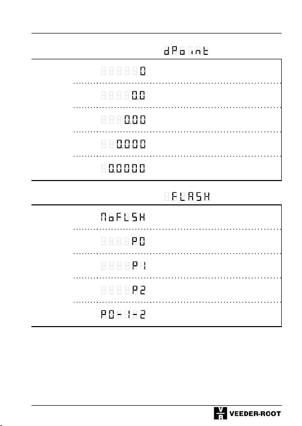
Function code F13, Display Row 1:
Decimal
point
0*
No decimal point
Pulse counter
1
2
3
4
1 decimal place
2 decimal places
3 decimal places
4 decimal places
Function code F14, Display Row 1:
Display
flashes
0*
1
2
3
4
No flashing
Flashes as long as P 0 is active
Flashes as long as P 1 is active
Flashes as long as P 2 is active
Flashes as long as one P is active
49
Page 50
Pulse counter
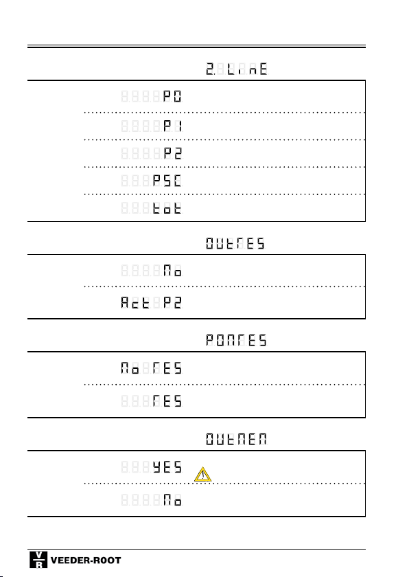
Function code F15, Display Row 1:
Display in
2nd row
0
Preset 0
1
2*
3
4
Preset 1
Preset 2
Prescaler
Totalizer
Function code F16, Display Row 1:
Output at
Reset (Interm.
Cut
0*
1
Do not activate Preset 2 during Reset
Activate Preset 2 during Reset
Function code F17, Display Row 1:
Power On
(Reset)
0*
1
Restore counter value
Reset at Power On
Function code F18, Display Row 1:
Output
signal
Memory
0
1*
Restart signal time after power fail
Do not restart signal time after power
fail
output switches
50
Page 51
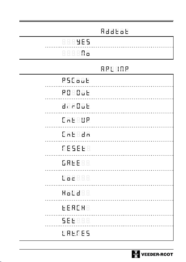
Function code F19, Display Row 1:
Addtl.
Totalizer
0
1*
Enabled
Disabled
Function code F22, Display Row 1:
Applica.
Input/
Output
0
1
Prescaler output
Output Preset 0
Pulse counter
2
3*
4
5
6
7
8
9
10
11
Directional output
Counter input - adding
Counter input – subtracting
Reset input
Gate input
Keylock input
Hold input (display lock)
Teach input
(count value becomes P 2)
Set input (Set to Preset 0)
Latch and Reset
(Save display at Reset)
51
Page 52
Pulse counter
Should you have a counter with interface, the
additional function codes F24 - F27 are described in the seperate manual for the interface
version.
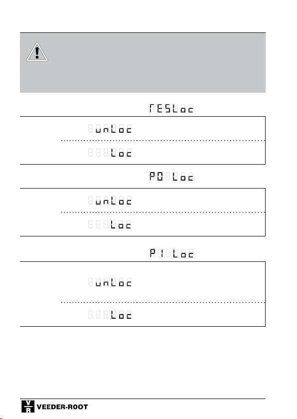
Function code F30, Display Row 1:
Lock Reset
key
0*
Enable keyboard reset
1
Function code F31, Display Row 1:
Lock
Preset 0
0*
1
Function code F32, Display Row 1:
Lock
Preset 1
0*
1
Keyboard reset locked / delayed
P 0 Setting enabled
P 0 Setting locked / delayed
P 1 Setting enabled
P 1 Setting locked / delayed
52
Page 53
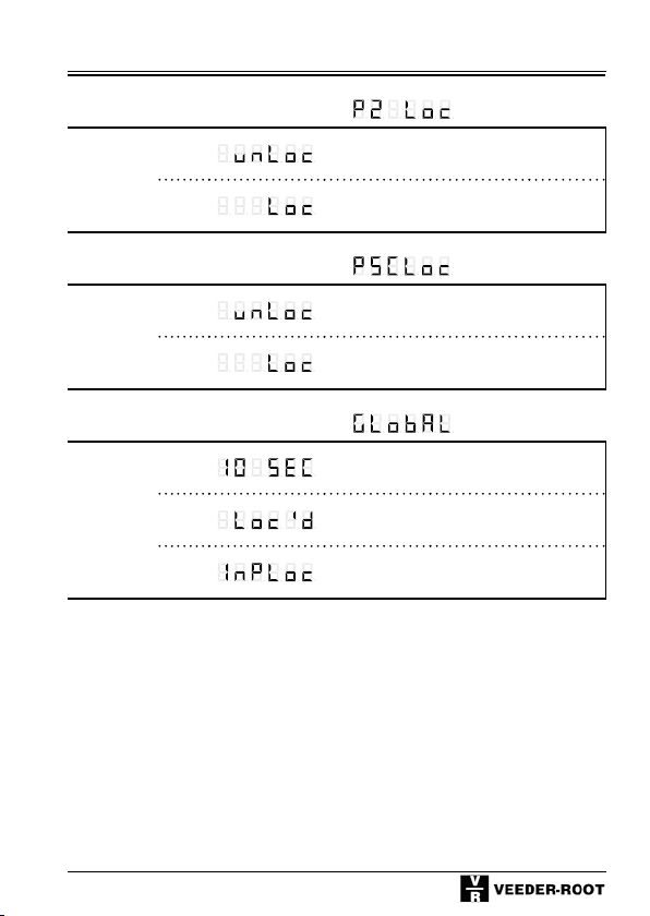
Function code F33, Display Row 1:
Pulse counter
Lock
Preset 2
0*
1
P 2 Setting enabled
P 2 Setting locked / delayed
Function code F34, Display Row 1:
Lock
Prescaler
setting
0*
1
PSC setting enabled
PSC Setting locked / delayed
Function code F35, Display Row 1:
Lock
Mode
0*
1
2
10 seconds delay
Completely locked
Lock mode depends on keylock input
53
Page 54

Tachometer
6 Tachometer
6.1 Tachometer Description
(Supplementing the General Description given in Chapter 4)
Operation:
A tachometer measures the period (PNP: time from one rising edge to the next
one); NPN: time period from a falling edge to the next one), and converts and
displays this time in 1/sec or 1/min.
Tachometer Mode of Operation:
The following modes of tachometer operation can be selected:
Unidirectional counting;
Unidirectional counting with directional input;
Differential counting, summation (totalizing);
Phase discrimination (quad) with single, double or quadruple evaluation;
Indication of ratio A/B and
Indication of percentage (A-B) /A in %
Decimal point
Tachometer mode of operation 0-4 (function code F1)
The decimal point only serves for better legibility and does not change the value.
Tachometer mode of operation 5 + 6 (function code F1)
The decimal point is included in the calculation and increases the resolution.
Output signals Mode of operation:
The tachometer uses the following limit values:
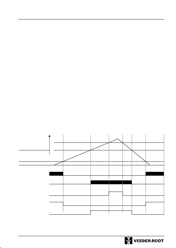
P 1 and 2 are limit (range) signals
Signal 1 is active at the displayed value of < P 1 and
Signal 2 is active at the displayed value of > P 2
Signal 0 is active at the displayed value of > P 0; (application output)
54
Page 55
Tachometer
Display unit:
Programmable: 1/sec or 1/min
Using the setting 1/min and prescaler 60 the display will show 1/hour.
Min. input frequency:
Programmable 1 Hz or 0.1 Hz.
If two edges do not occur within 1 s or respectively 10s,
a value of 0 will be displayed.
Startup suppression:
Programmable Yes/No
During the startup the lower limit signal is suppressed until the lower limit
value is exceeded for the first time.
The startup suppression will become active again, if the minimum frequency is
fallen below.
6.2 Signal diagram - Output signals
Input frequency
P 0
P 2
P 1
Output signals
P 1 (Relay)
P 2 (Relay)
P 0 electronic
(Application output)
Frequency Hz
P 1 electronic
P 2 electronic
55
Page 56
Tachometer
6.3 Programming the tachometer function codes
Programming
mode
+ or
Keep pressed
and
simultaneously
turn
Voltage On
Alternative
display of
Function code:
Change function
setting
press press press
+
Function code F0, Display Row 1:
Function No.
Factory
Setting
(Defaults)
Display
Row 2
0*
1
Save and change
to next function
The function codes are displayed as
text in row 1.
By pressing both keys simultane-
ously you can change to the nume-
rical display (F 0 to F 35). After
pressing these keys once again the
number of the selectable options
will be displayed in addition. This
setting will be stored.
No function
All function codes are set to the values marked with *
Return to
display mode
56
Page 57
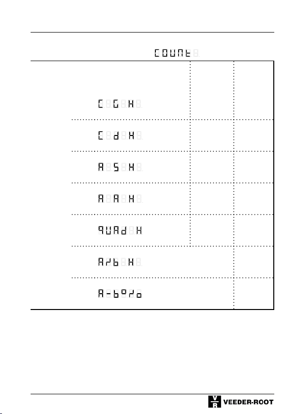
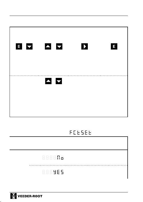
Function code F1, Display Row 1:
Tachometer
Input A Input B Input C
Tacho
mode of
operation
0*
1
Count
input
Count
input
Gate
Direct.
input
Hold
(Display
memory)
Hold
(Display
memory)
Hold
2
Adding subtracting
(Display
memory)
Hold
3
Adding Adding
(Display
memory))
Hold
4
Channel A Channel B
(Display
memory)
Hold
5
Channel A / Channel B
(Display
memory)
6
(A-B) / A in %
(Difference in % of A)
Hold
(Display
memory)
57
Page 58
Tachometer
Function code F2, Display Row 1:
Edge
0*
Evaluation/
Quadrat.
1
evaluation
2
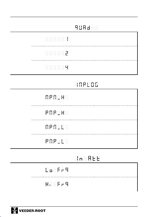
Function code F3, Display Row 1:
PNP/
NPN-
0
Logic
1*
2
3
Function code F4, Display Row 1:
Input
damping
(Attenuat)
0
1*
Single evaluation
Dual evaluation
Quadruple evaluation
NPN 8 V-Level
PNP 8 V-Level
NPN TTL-Level
PNP TTL-Level
30 Hz attenuation (e.g. for
mechanical contacts)
F max. (see chapter 4 und 10)
58
Page 59
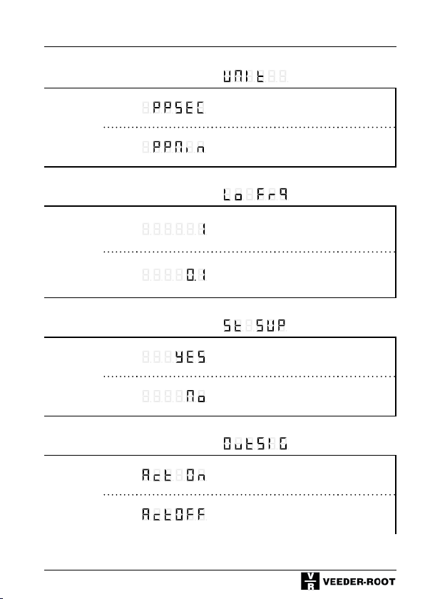
Function code F5, Display Row 1:
Display
Unit
0*
Tachometer
Pulse per second (1/sec)
1
Function code F6, Display Row 1:
Min.
Input
frequency
0*
1
Function code F7, Display Row 1:
Startupsuppress.
0
1*
Function code F9, Display Row 1:
Output
signal
0*
1
Pulse per minute (1/min)
1 Hz
(if no further pulse is received after
1s, the display will return to 0)
0,1 Hz
(if no further pulse is received after
1s, the display will return to 0)
With startup suppression
Without startup suppression
Active On
Active Off
59
Page 60
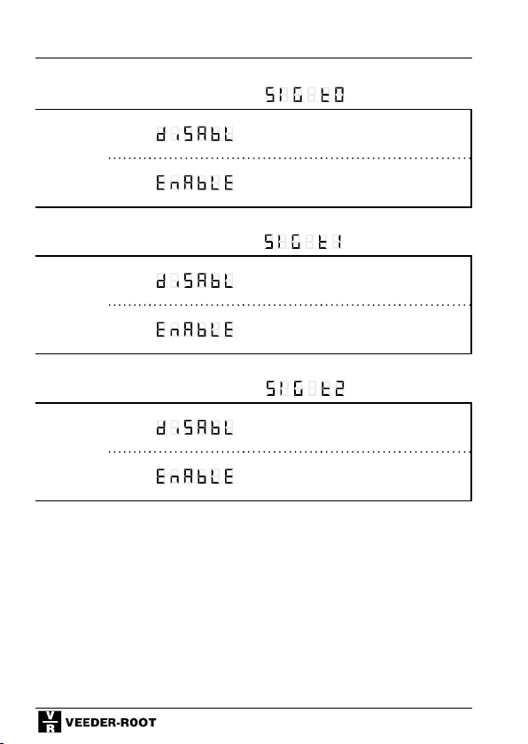
Tachometer
Function code F10, Display Row 1:
P 0
0*
Disabled / no Output signal
Addtl.
Upper
limit
1
Additional range signal > P 0
Function code F11, Display Row 1:
P 1
Lower
limit
0*
1
Disabled / no Output signal
Range signal < P 1
Function code F12, Display Row 1:
P 2 Upper
0*
limit
1
Disabled / no Output signal
Range signal > P 2
60
Page 61
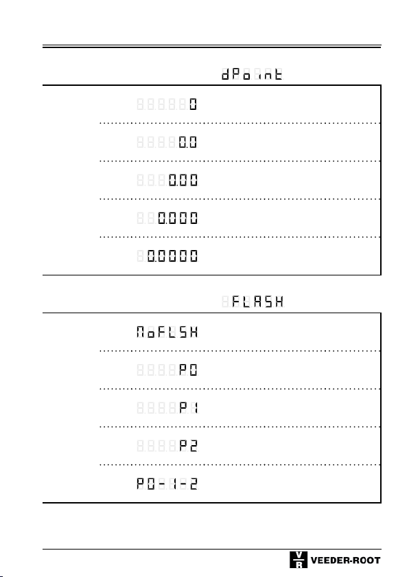
Function code F13, Display Row 1:
Decimal
place
0*
No decimal point
Tachometer
1
2
3
4
1 Decimal place
2 Decimal places
3 Decimal places
4 Decimal places
Function code F14, Display Row 1:
Display
flashes
0*
1
2
3
4
Do not flash
Flashes as long as P 0 active
Flashes as long as P 1 active
Flashes as long as P 2 active
Flashes if one preset is active
61
Page 62
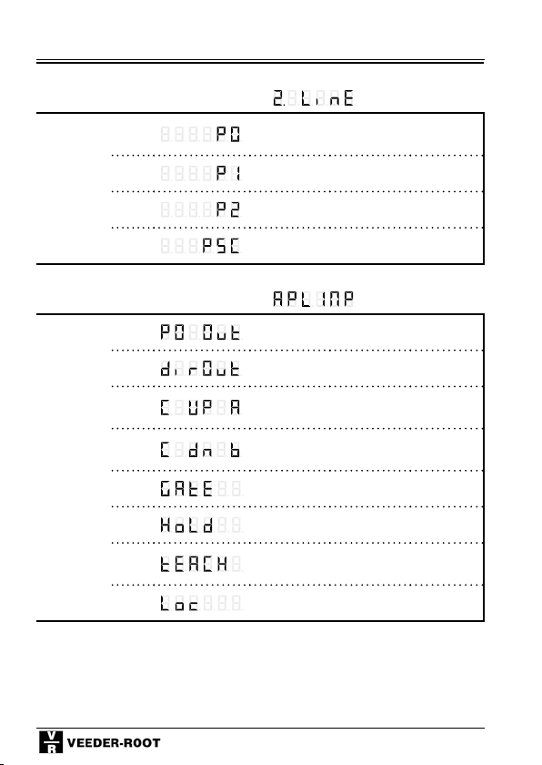
Tachometer
Function code F15, Display Row 1:
Display in
2nd row
0
1
Preset 0
Preset 1
2*
3
Preset 2
Prescaler
Function code F22, Display Row 1:
Application
Input/
Output
0
1
2*
3
4
5
6
7
Output Preset 0
Directional output
Count input adding, or
2nd count input A
Count input subtracting, or
2nd counter input B
Gate Input
Hold-Input (display memory)
Teach Input
(count value becomes P 2)
Keylock-Input
62
Page 63
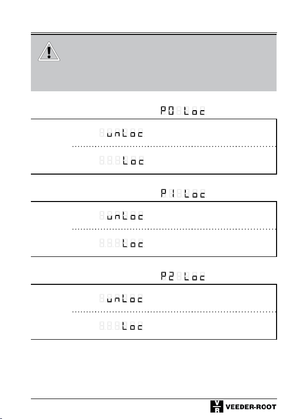
Should you have a counter with interface, the
additional function codes F24 - F27 are described in the seperate manual for the interface
version.
Function code F31, Display Row 1:
Tachometer
Lock Preset 0 Setting
0*
1
P 0 Setting enabled
P 0 Setting locked / delayed
Function code F32, Display Row 1:
Lock Preset 1 Setting
0*
1
P 1 Setting enabled
P 1 Setting locked / delayed
Function code F33, Display Row 1:
Lock Preset 2 Setting
0*
1
P 2 Setting enabled
P 2 Setting locked / delayed
63
Page 64
Tachometer
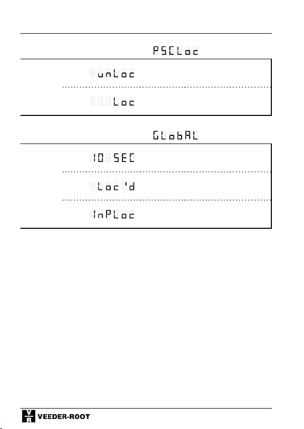
Function code F34, Display Row 1:
Lock
0*
PSC Setting enabled
Prescaler
Setting
1
PSC Setting locked / delayed
Function code F35, Display Row 1:
Lock
Mode
0*
1
2
10 seconds delay
Completely locked
Lock mode depends on keylock Input
64
Page 65

Timer
7 Timer
7.1 Timer Description
(Supplementing the General Description in Chapter 4)
Function:
The timer counts seconds, minutes or hours.
Depending on the resolution (see below) the smallest units to be recorded are
0,1 ms.
Combined with the prescaler (see below), quantities can be measured as a
function of time.
Time formats:
4 time formats are available:
Seconds, minutes, hours and HH:MM:SS
Resolution:
By shifting the decimal place, a resolution of up to 4 decimal places can be
programmed; the smallest resolution is 0,1 ms.
Thetimeformat“secondswithfourdecimalplaces”shows0.1milliseconds.
Thetimeformat“secondswiththreedecimalplaces”showsmilliseconds.
Thetimeformat“minuteswithtwodecimalplaces”shows1/100minutes
Prescaler:
During the timer operation the prescaler has to be disabled or set to 01,0000.
The prescaler can be used to record quantities, provided that the quantity per
time unit is known.
Example: A volume of 3 liters per second is supplied.
Settings:Timeformat“seconds”,prescaler3,0000
Display: Supplied volume in liters as a function of time.
The prescaler cannot be used with the time format HH:MM:SS
as it is not active (effective) in this format.
65
Page 66

Timer
Timer mode of operation:
The following modes of timer operation can be selected:
Cumulative measurement following the pulse-width measuring principle
(Cumulative measurement as long as input A is active)
Cumulative measurement following the cycle-duration principle
(Cumulative measurement from rising edge Input A to falling edge of Input A)
Cumulative measurement A=Run, B=Stop (cumulative measurement from
rising edge Input A to rising edge Input B)
Single-pulse measurement following the pulse-width measurement principle (Measure as long as Input A is active)
Single-pulse measurement following the cycle-duration principle (Measu-
rement from rising edge Input A to rising edge of Input A)
Single-pulse measurement A=Run, B=Stop (Cumulative measurement from
rising edge Input A to rising edge Input B)
Manual Start / Stop via keyboard:
The Start / Stop function can be programmed via the keyboard.
Start: Press the UP button for 0.5s
Stop: Press the DOWN button.
Output signals –Function:
A coincidence signal:Thetimeroperatesinthe“coincidence”mode,i.e.the
output signals are enabled for the programmed period of time after reaching
the selected preset value
B trail signal:P2andP0operateinthe“coincidence”mode,i.e.theoutput
signals are enabled for the programmed period of time when reaching the selected preset value. P 1 is a trail preset and not absolute to 0, but relative to P
2.
If the setting is F8=1, the following will apply:
Signal 1 is returned at P 2 – P 1
Example: P 2=1000, P 1=200, Signal 1 at 800;
If P1 is negative: P 2=1000, P 1=(-200), Signal 1 at 1200
If the setting is F8=2, the following will be applicable:
Signal 1 is returned at P 2 + und – P 1
(Example: P 2=1000, P 1=200, Signal 1 at 800 or/and 1200)
C range signal: P 1 and 2 are range signals:
Signal 1 is active at timer reading < P 1 and
Signal 2 is active at timer reading > P 2
66
Page 67
Timer
D batch mode: The timer can also be programmed to act as a batch counter.
In this case, P 2= main preset value; P 1= Batch preset.
In the Batch mode of operation, only positive entries are possible for P1;
negative entries will be stored as positive values.
This mode is ideal to default a process time and the number of process sequences (runs).
Additional totalizer:
The additional totalizer is used to sum up all the times (even after repeated
resetting of the main counter). The totalizer is reset separately.
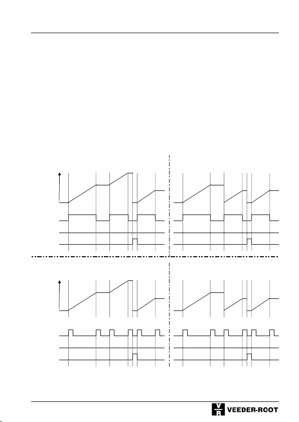
7.2 Signal Diagrams - Input signals
F7 = 0 Cumulative Measurement acc. to F7 = 3 Single-pulse Measurement acc. to
pulse-width measuring principle pulse-width measuring principle
Time
Display
Input A
Input B
InputC
Reset
F7 = 0 Cumulative measurement acc. to
cycle-duration measuring principle
Time
Display
Input A
Input B
Input C
Reset
Start
Stop
Start
Start
Stop
F7 = 0 Cumulative measurement acc. to
cycle-duration measuring principle
tratS
Stop
Stop
tratS
Start
Stop
Stop
67
Page 68
Timer
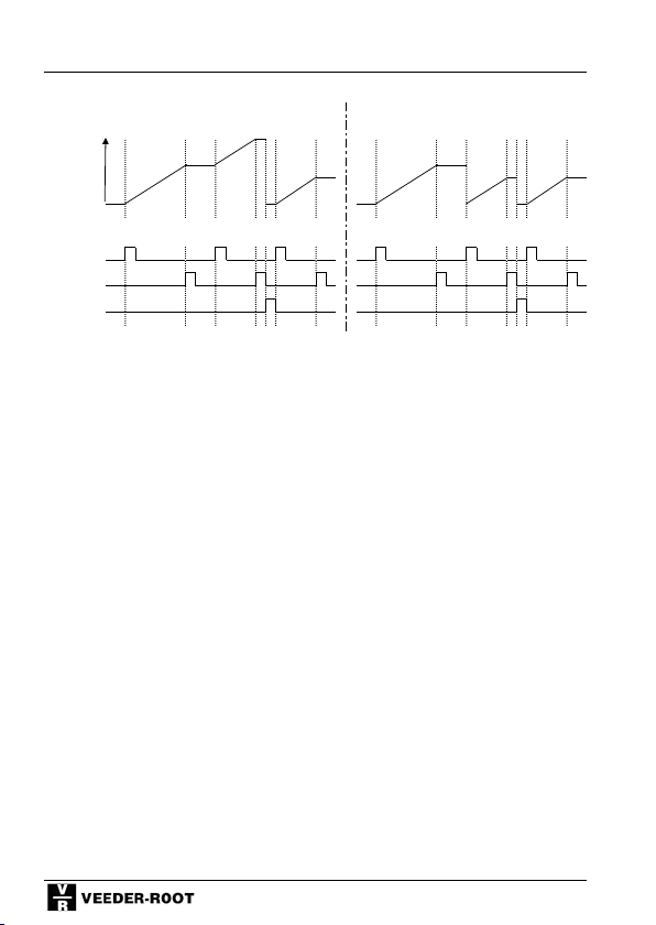
F7 = 0 Cumulative Measurement acc. to F7 = 3 Single-pulse Measurement acc. to
pulse-width measuring principle pulse-width measuring principle
Input A
Input B
InputC
Reset
Input A
Input B
Input C
Reset
tratS
Stop
tratS
Stop
Start
Stop
Time
Display
Time
Display
Start
Stop
Stop
Start
Start
Stop
F7 = 0 Cumulative measurement acc. to
cycle-duration measuring principle
F7 = 0 Cumulative measurement acc. to
cycle-duration measuring principle
F7 = 0 Cumulative measurement acc. to
A = Run, B = Stop
Time
Display
Start
Stop
Start
Stop
Input A
Input B
Input C
Reset
7.3 Signal Diagrams - Output signals
Start
F7 = 0 Cumulative measurement acc. to
A = Run, B = Stop
tratS
Stop
Stop
Start
The output signals of the timer can be derived from the pulse counter (see 5.3)
or, respectively, batch counter (see 9.2) functions.
tratS
Stop
Stop
68
Page 69
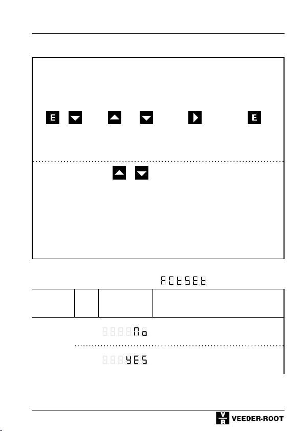
7.4 Programming the Timer function codes
Timer
Program-
ming mode
+ oder
Keep pressed and
simultaneously
turn Voltage On
Alternative
display of
function codes
Change
function
setting
press press press
+
Function code F0, Display Row 1:
Function
Factory
Setting
(Defaults)
No.
0*
1
Display
Row 2
Save and
change to
next
function
The function codes are displayed
as text in row 1.
By pressing both keys simultane-
ously you can change to the
numerical display (F 0 to F 35).
After pressing these keys once
again the number of the selecta-
ble options will be displayed in
addition. This setting will be
No function
All function codes are set to the values marked with *
Return to
display mode
stored.
69
Page 70
Timer
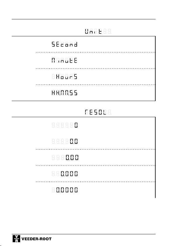
Function code F1, Display Row 1:
Time unit
0*
Seconds
1
2
3
Function code F2, Display Row 1:
Resolution
0*
1
2
3
4
Minutes
Hours
HH:MM:SS
No decimal point
1 decimal place
2 decimal places
3 decimal places
4 decimal places
70
Page 71
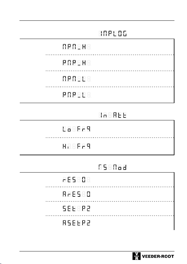
Function code F3, Display Row 1:
PNP/NPNLogic
0
Timer
NPN 8 V-Level
1*
2
3
Function code F4, Display Row 1:
Input
damping
(Attenuation)
0
1*
Function code F5, Display Row 1:
Set / Reset- Mode
0*
1
2
3
PNP 8 V-Level
NPN TTL-Level
PNP TTL-Level
30 Hz damping (attenuation)
(e.g. for mechanical contacts)
F max. (see chapter 4 and 10)
Reset to 0
Automatic set to 0
after reaching Preset value 2
Set to Preset 2
Automatically sets to Preset 2
after reaching 0.
71
Page 72
Timer
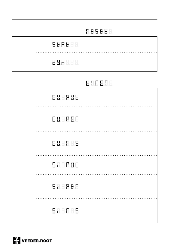
Function code F6, Display Row 1:
dynam/
static
Reset
Function code F7, Display Row 1:
TimerMode of
Operation
0*
1
0
1*
2
3
4
5
Static Reset (as long as the signal is
applied)
Dynamic Reset (ready to count after
reset, even if reset signal is applied for
a longer time)
Cumulative measurement - pulsewidth (counts as long as Input A is
active)
Cumulative measurement – cycle duration (counts from rising edge of
start signal to rising edge of stop signal).
Cumulative measurement A=Run B=Stop
(counts from rising edge of start signal to rising edge of stop signal).
Single-pulse measurement – pulsewidth (counts as long as Input A is
active)
Single-pulse measurement – cycle duration (counts from rising edge of
start signal to rising edge of stop signal).
Single-pulse measurement - A=Run
B=Stop (counts from rising edge of
start signal to rising edge of stop signal)
72
Page 73
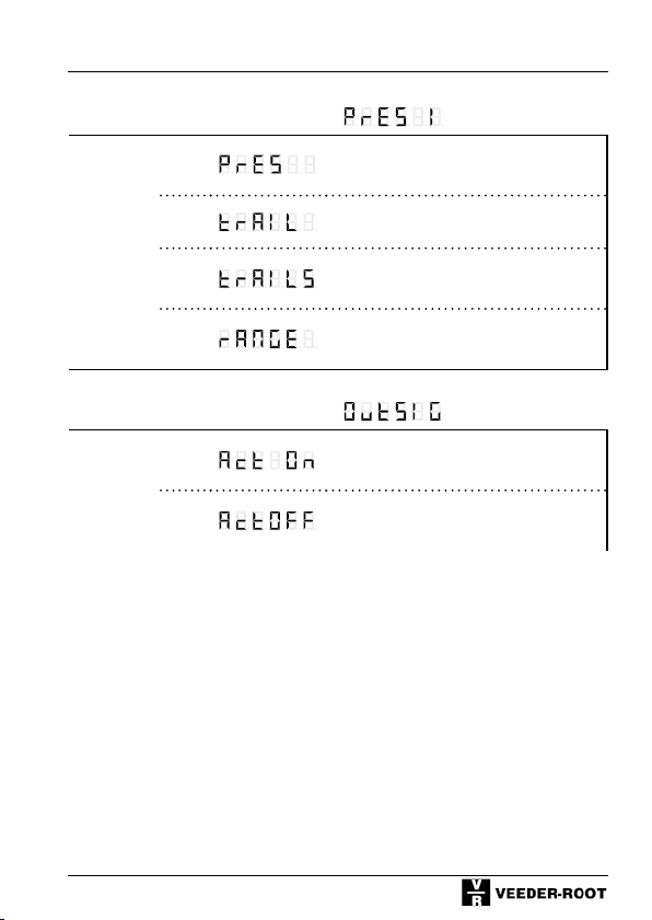
Function code F8, Display Row 1:
Mode
Preset 1
0*
1
2
Timer
P 1 normal preset; absolute to counter
reading (coincidence signal)
P 1 is a trail preset with prefix (relative to P 2)
P 1 as a symmetric trail preset
(relative to P 2)
3
P 1 and P 2 are range signals
(Sign.1<P1, Sign.2>P2)
Function code F9, Display Row 1:
Output
signal
0*
1
Active On
Active Off
73
Page 74
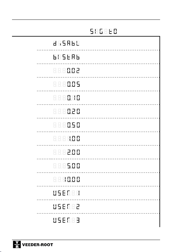
Timer
Function code F10, Display Row 1:
Signal
time P 0
0
Disabled / No output signal
1
2
3
4*
5
6
7
8
9
10
11
12
13
Bistable, reset with Preset 2 or Reset
0,02 s
0,05 s
0,10 s
0,20 s
0,50 s
1,00 s
2,00 s
5,00 s
10,00 s
User setting 1 (0-599,99 s)
User setting 2 (0-599,99 s)
User setting 3 (0-599,99 s)
74
Page 75
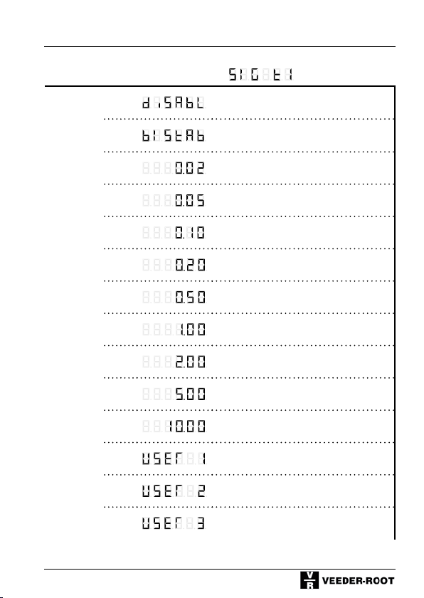
Function code F11, Display Row 1:
Signal
time P 1
0
1
Disabled / no output signal
Bistable, reset with Preset 2 or
Reset
Timer
2
3
4*
5
6
7
8
9
10
11
12
13
0,02 s
0,05 s
0,10 s
0,20 s
0,50 s
1,00 s
2,00 s
5,00 s
10,00 s
User setting 1 (0-599,99 s)
User setting 2 (0-599,99 s)
User setting 3 (0-599,99 s)
75
Page 76
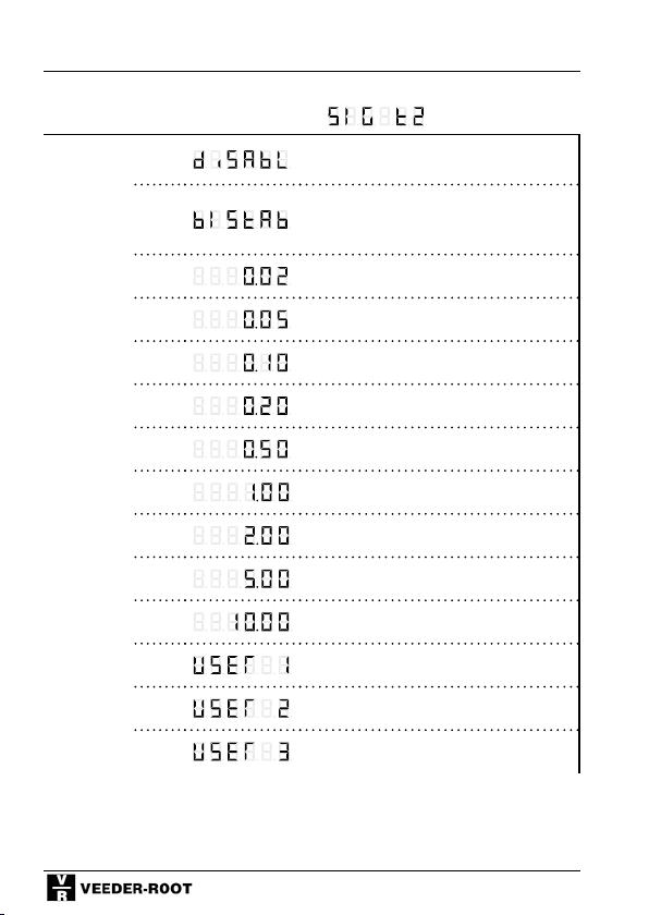
Timer
Function code F12, Display Row 1:
Signal
time P 2
0
1
2
Disabled / No output signal
Bistable; Reset function cannot be
used in connection with automatic
Reset
0,02 s
3
4*
5
6
7
8
9
10
11
12
13
0,05 s
0,10 s
0,20 s
0,50 s
1,00 s
2,00 s
5,00 s
10,00 s
User setting 1 (0-599,99 s)
User setting 2 (0-599,99 s)
User setting 3 (0-599,99 s)
76
Page 77
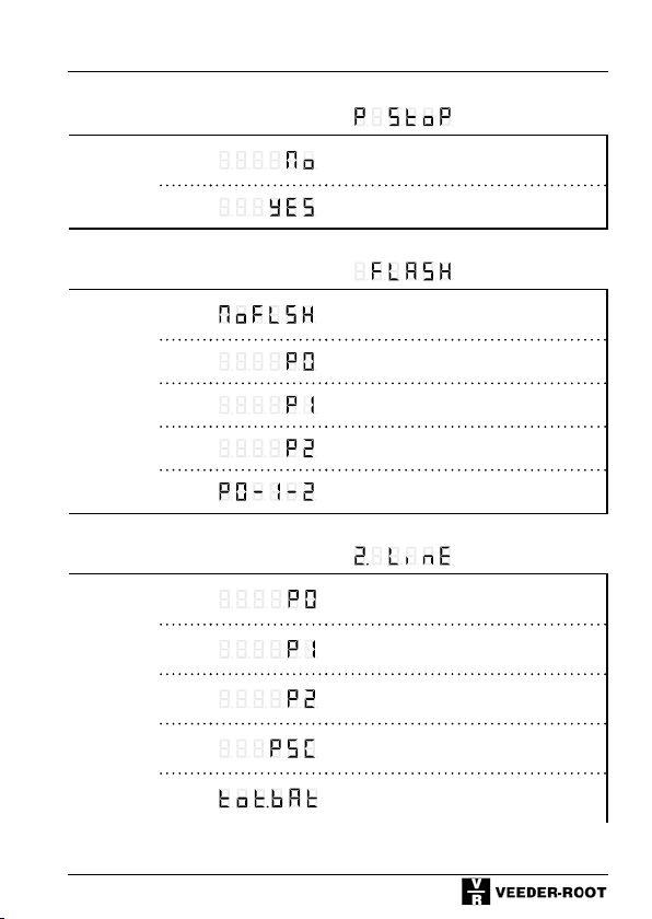
Function code F13, Display Row 1:
Stop after
reaching
the main
Preset
0*
1
No Stop when main Preset is reached
(P 2)
Stop when main Preset is reached (P 2)
Function code F14, Display Row 1:
Display
flashes
0*
1
no flashing
Flashes as long as P 0 is active
Timer
2
3
4
Flashes as long as P 1 is active
Flashes as long as P 2 is active
Flashes as long as 1 P is active
Function code F15, Display Row 1:
Display in
2nd Row
0
1
2*
3
4
Preset 0
Preset 1
Preset 2
Prescaler
Totalizer / Batchcounter
77
Page 78
Timer
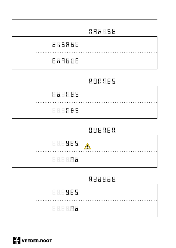
Function code F16, Display Row 1:
Start /
Stop via
Keyboard
(manual)
Function code F17, Display Row 1:
Power On
Reset
0*
1
0*
Start / Stop locked via keys
UP key=Start; DOWN key = Stop
Start / Stop enabled via keys
UP key =Start; DOWN key =Stop
Restore counter value
1
Function code F18, Display Row 1:
Output
Signal
Memory
0
1*
Function code F19, Display Row 1:
Addtl.
Totalizer
0
1*
Reset at Power On
Restart signal time after power fail
output switches
Do not restart signal time after power
fail
Enabled
Disabled
78
Page 79
Function code F20, Display Row 1:
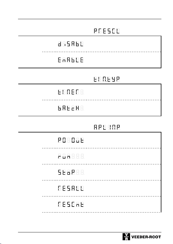
Prescaler
0*
Prescaler not active
Timer
1
Prescaler active
Function code F21, Display Row 1:
Timer Type
0*
1
Preset timer
Batch timer
Function code F22, Display Row 1:
Application
Output
0
1*
2
3
4
Output Preset 0
Run-Input
Stop-Input
Reset counter and totalizer or batch
counter
Reset – only counter
79
Page 80
Timer
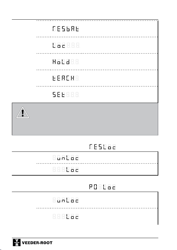
5
6
7
8
9
Reset - only totalizer or batch counter
Keylock input
Hold input (display memory)
Teach Input (count value becomes P
2)
Set Input (set to Preset 0)
Should you have a counter with interface, the
additional function codes F24 - F27 are described in the seperate manual for the interface
version.
Function code F30, Display Row 1:
Lock Reset
Key
0*
1
Function code F31, Display Row 1:
Lock Preset 0 Setting
0*
1
Keyboard reset enabled
Keyboard reset locked / delayed
P 0 Setting enabled
P 0 Setting locked / delayed
80
Page 81
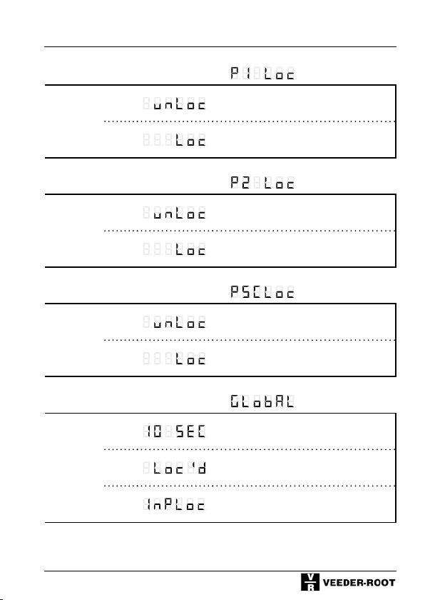
Function code F32, Display Row 1:
Lock Preset 1 Setting
0*
1
P 1 Setting enabled
P 1 Setting locked / delayed
Function code F33, Display Row 1:
Lock Preset 2 Setting
0*
1
P 2 Setting enabled
P 2 Setting locked / delayed
Function code F34, Display Row 1:
Lock Prescaler Setting
0*
1
PSC Setting enabled
PSC Setting locked / delayed
Function code F35, Display Row 1:
Lock
Mode
0*
10 seconds delay
Timer
1
2
Completely locked
Lock mode depends on keylock input
81
Page 82

Shift Counter
8 Shift Counter
8.1 Shift Counter Description
(Supplementing the general description under chapter 4)
Function:
2-shift counters enable the acquisition of 2 separate partial sums.
Counter input A acts on partial sum 1, whereas counter input B acts on partial
sum 2.
Both partial sums are counted positively; the total sum is calculated mathematically and corresponds to the summed-up total (or respectively, the difference) of the partial sums.
The total sum remains unchanged after resetting one of the partial sums.
Counter mode of operation:
The following counter modes of operation can be selected:
Difference counting and summation (totalizing)
Output signals - mode of operation:
Thecounteroperatesinthe“coincidence”mode,i.e.theoutputsignalsare
enabled for the programmed period of time after reaching the selected Preset
value.
The total sum acts on Preset 0
Partial sum 1 acts on Preset 1
Partial sum 2 acts on Preset 2
Reset:
After a reset at input C, both partial sums and the total sum are reset.
When resetting via the application input it is possible to reset one or both of
the partial sums or the total sum, depending on the selected programming.
When resetting via the keyboard, only the value shown on the display is reset.
Totalizer:
The totalizer sums up all the input pulses, even if the partial sums and the total sum are reset. The totalizer can only be reset manually.
82
Page 83
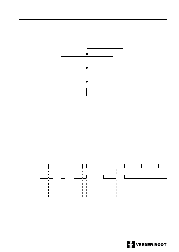
Shift Counter
Adding/Adding (F1= A A r)
8.2 Scrolling between Total Sum and Partial Sums
The Shift key is used to scroll between the total sum and
partial sums 1 and 2.
Total sum
Partial sum 1
Partial sum 2
If a partial sum is shown, SU1 or SU2 will appear flashing in the lower display
bar.
8.3 Signal diagrams - Inputs (PNP Logic)
Input A
Input B
Counter reading
Partial sum 1 1 2 3 4 5 6 7
Partial sum 2 1 2 3 4
Total sum 1 2 3 4 5 6 7 9 10 11
83
Page 84
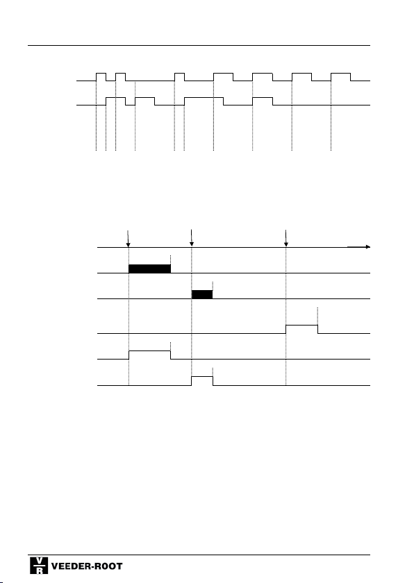
Shift Counter
Adding/Subtracting (F1= A S r)
Input A
Input B
Counter reading
Partial sum 1 1 2 3 4 5 6 7
Partial sum 2 1 2 3 4
Total sum 1 0 1 0 1 0 1 1 2 3
8.4 Signal Diagrams - Output signals
Output signals - monostable
Coincidence signals P 0/Total Sum (F10), P 1/Partial sum 1 (F11), P 2/Partial sum 2 (F12) monostable
Counter reading Partial sum1 Partial sum 2 Total sum
P 1 (Relay)
P 2 (Relay)
P 0 electronic time
(Application output)
P 1 electronic
P 2 electronic
Preset 1 Preset 2 Preset 0
Signal time
Signal
time
Signal
Signal time
Signal
time
84
Page 85
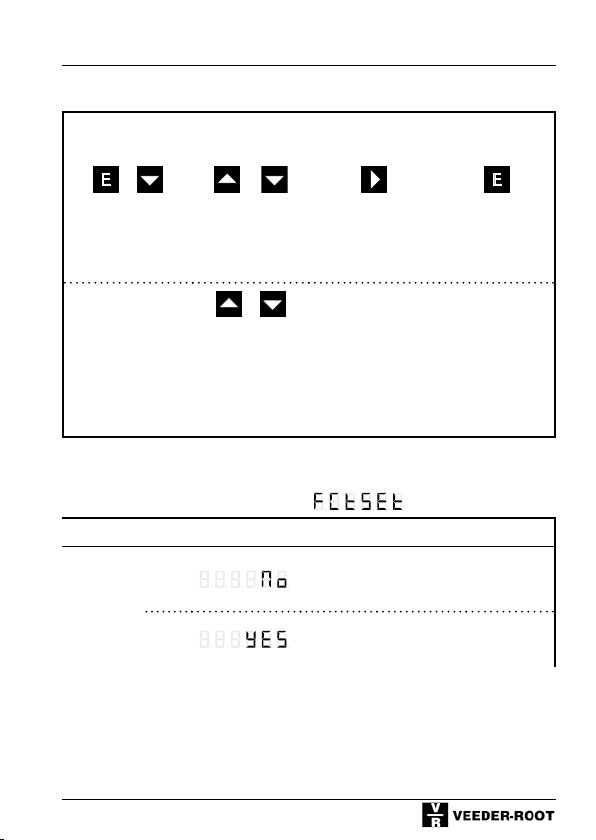
Shift Counter
8.5 Programming the Shift Counter Function Codes
Programming
mode
+ or
Keep pressed and
simultaneously
turn
Voltage On
Alternative dis-
play of
Function codes
Change func-
tion setting
press press press
+
Function code F0, Display Row 1:
Function No. Display Row 2
Factory
Setting
(Defaults)
0*
1
Save and change
to next function
The function codes are displayed as
text in row 1. By pressing both keys
simultaneously you can change to
the numerical display (F 0 to F 35).
After pressing these keys once again
the number of the selectable options will be displayed in addition.
This setting will be stored.
No function
All function codes are set to the values marked with *
Return to dis-
play mode
85
Page 86
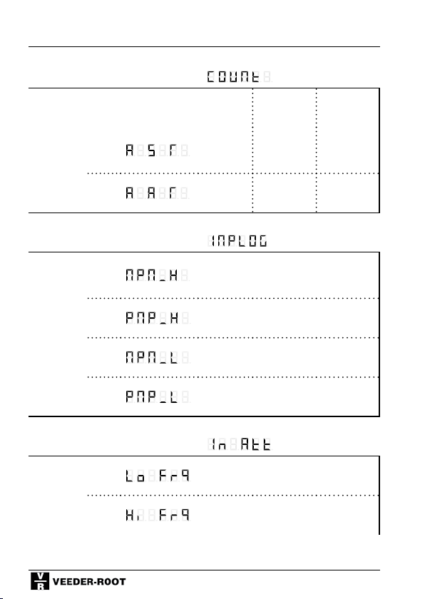
Shift Counter
Function code F1, Display Row 1:
Input A Input B Input C
Counter
mode of
0
Operation
1*
Function code F3, Display Row 1:
PNP/
NPN-Lo-
0
gic
1*
2
3
Function code F4, Display Row 1:
Input
Attenuat.
0
1*
Adding Subtracting Reset
Adding Adding Reset
NPN 8 V-Level
PNP 8 V-Level
NPN TTL-Level
PNP TTL-Level
30 Hz damping (attenuation); e.g. for
mechanical contacts
F max. (see chapter 4 and 10)
86
Page 87
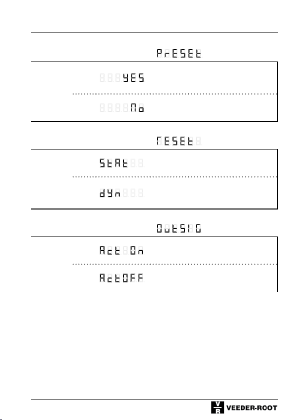
Function code F5, Display Row 1:
With /
without
Preset
0
Shift Counter
With Preset
1*
Function code F6, Display Row 1:
Dynamic/
static
Reset
0*
1
Function code F9, Display Row 1:
Output
signal
0*
1
Without Preset
Static reset (reset as long as signal is
applied)
Dynamic Reset (ready to count after
reset, even if reset signal is applied
for a longer time)
Active On
Active Off
87
Page 88
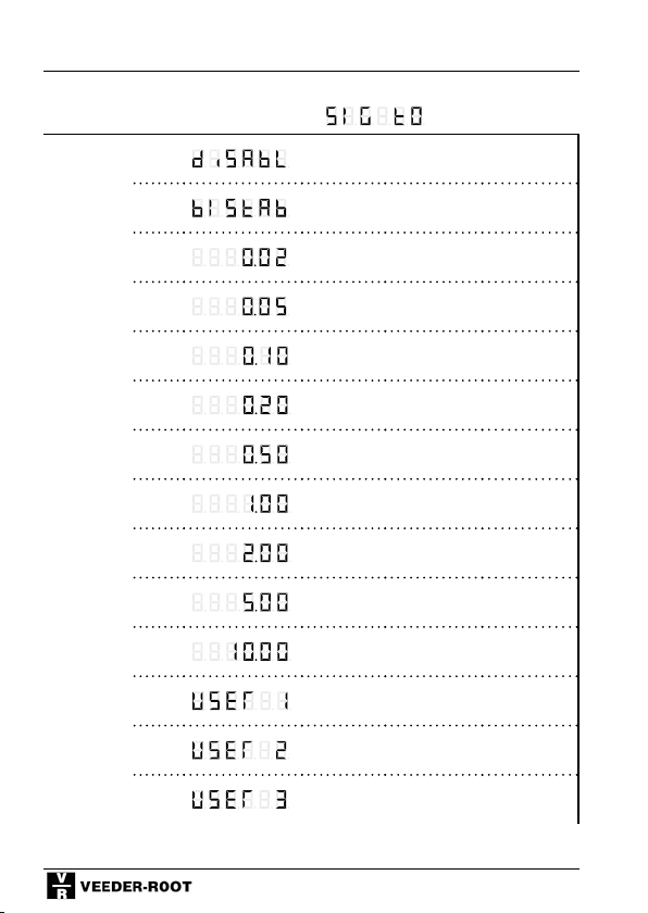
Shift Counter
Function code F10, Display Row 1:
Signal
time P 0
Total
Sum
0
1
2
3
4*
5
6
7
8
9
10
11
12
Disabled / no output signal
Bistable; reset with Reset
0,02 s
0,05 s
0,10 s
0,20 s
0,50 s
1,00 s
2,00 s
5,00 s
10,00 s
User setting 1 (0-599,99 s)
User setting 2 (0-599,99 s)
13
User setting 3 (0-599,99 s)
88
Page 89
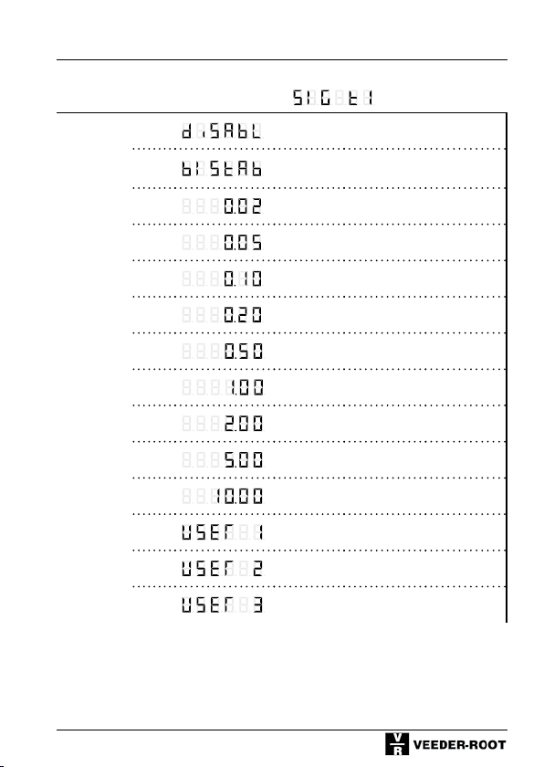
Function code F11, Display Row 1:
Signal
time P 1
Partial
sum 1
0
1
2
Shift Counter
Disabled / no output signal
Bistable; reset with Reset
0,02 s
3
4*
5
6
7
8
9
10
11
12
13
0,05 s
0,10 s
0,20 s
0,50 s
1,00 s
2,00 s
5,00 s
10,00 s
User setting 1 (0-599,99 s)
User setting 2 (0-599,99 s)
User setting 3 (0-599,99 s)
89
Page 90
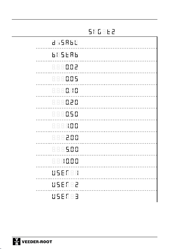
Shift Counter
Function code F12, Display Row 1:
Signal
time P 2
Partial
sum 2
0
1
Disabled / no output signal
Bistable; reset with Reset
2
3
4*
5
6
7
8
9
10
11
12
13
0,02 s
0,05 s
0,10 s
0,20 s
0,50 s
1,00 s
2,00 s
5,00 s
10,00 s
User-Einstellung 1 (0-599,99 s)
User-Einstellung 2 (0-599,99 s)
User-Einstellung 3 (0-599,99 s)
90
Page 91
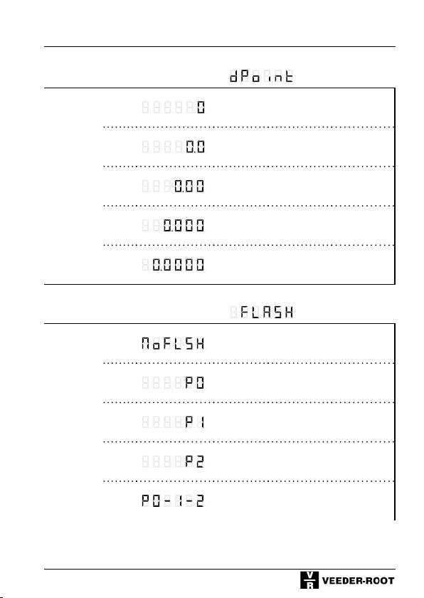
Function code F13, Display Row 1:
Decimal
Point
0*
No decimal point
Shift Counter
1
2
3
4
1 decimal place
2 decimal places
3 decimal places
4 decimal places
Function code F14, Display Row 1:
Display
flashes
0*
1
2
3
4
No flashing
Flashes as long as P 0 is active
Flashes as long as P 1 is active
Flashes as long as P 2 is active
Flashes as long as one Preset is active
91
Page 92
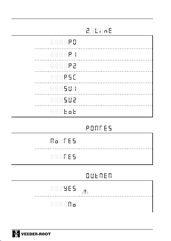
Shift Counter
Function code F15, Display Row 1:
Display in
2nd Row
0
1
Preset 0
Preset 1
2*
3
4
5
6
Function code F17, Display Row 1:
Power-On
Reset
0*
1
Function code F18, Display Row 1:
Output
Signal
Memory
0
1*
Preset 2
Prescaler
Partial sum 1
Partial sum 2
Totalizer
Restores the counter value
Reset at Power On
Restart signal time after power fail
output switches
Do not restart signal time after power
fail
92
Page 93
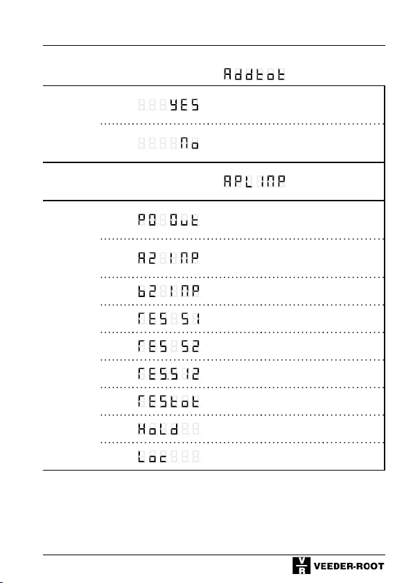
Function code F19, Display Row 1:
Shift Counter
0
Additional totalizer is enabled
Addtl.
Totalizer
1*
No additional totalizer
Function code F22, Display Row 1:
Application
Input/
Output
0
1*
2
3
4
5
6
7
9
Output Preset value 0
2nd counter input partial sum 1
2nd counter input partial sum 2
Reset of partial sum 1
Reset of partial sum 2
Reset of both partial sums
Reset of total sum
Hold Input (display memory)
Keylock Input
93
Page 94
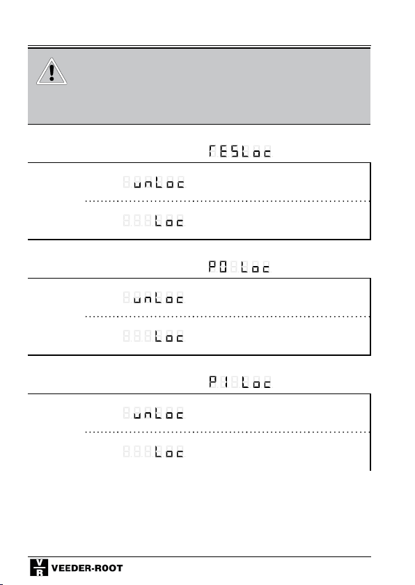
Shift Counter
Should you have a counter with interface, the
additional function codes F24 - F27 are described in the seperate manual for the interface
version.
Function code F30, Display Row 1:
Lock
Reset key
0*
Keyboard reset enabled
1
Function code F31, Display Row 1:
Lock
Preset 0
0*
1
Function code F32, Display Row 1:
Lock
Preset 1
0*
1
Keyboard reset locked / delayed
P 0 Setting enabled
P 0 Setting locked / delayed
P 1 Setting enabled
P 1 Setting locked / delayed
94
Page 95
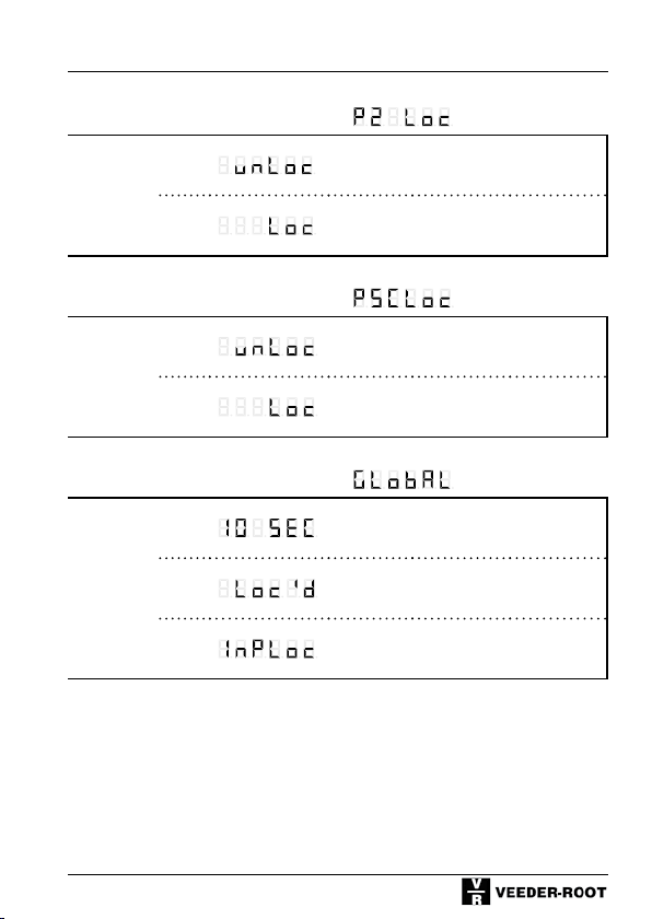
Function code F33, Display Row 1:
Shift Counter
0*
P 2 Setting enabled
Lock
Preset 2
1
P 2 Setting locked / delayed
Function code F34, Display Row 1:
Lock
Prescaler
Setting
0*
1
PSC Setting enabled
PSC Setting locked / delayed
Function code F35, Display Row 1:
Lock
Mode
0*
1
2
10 seconds delay
Completely locked
Lock mode depends on keylock input
95
Page 96

Batch Counter
9 Batch Counter
9.1 Batch Counter Description
(Supplementing the general description in Chapter 4)
Function:
Preset 2 is the main Preset setting.
Preset 1 is the Batch Preset or, respectively, the preset value of the 2nd totalizer.
In the batch operation the batch counter counts how often the main Preset is
activated.
Example of an application: during length cutting operations, for example, both
the lengths (main preset) and number (batch preset) can be monitored.
In the Batch mode of operation, only positive entries are possible for P1;
negative entries will be stored as positive values.
Counter mode of operation:
The following modes of operation can be adjusted for the counter:
Unidirectional counting, adding or subtracting;
Unidirectional counting with directional input;
Difference counting, summation and phase discrimination (quad)
with single, double or quadruple evaluation.
Output signals Mode of Operation:
The counter operates in the coincidence mode, i.e. the output signals are enabled for the programmed duration when the selected preset value is reached.
Prescaler Output PSC-out:
The Prescaler output is an application output.
With each increase of the counter reading the number of output pulses corresponds to the respective number of increments.
The pulse length of the prescaler output corresponds to a frequency of 500 Hz.
When using the prescaler output the max. input frequency is:
F max = 500 / PSC.
So it is possible that the maximum input frequency can not be reached.
96
Page 97
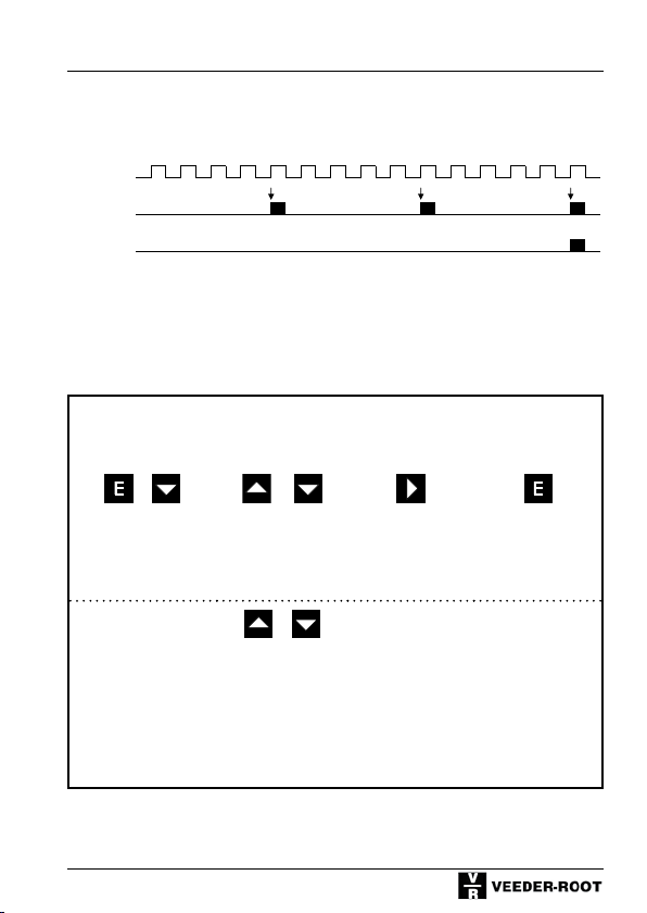
Batch Counter
9.2 Signal Diagrams - Inputs and Outputs
Unidirectional count (F1 = C G r), Batch counter (F19 = bAtch),
Preset 2 (Main Preset = 5, Preset 1 (Batch Preset) = 3
Input A
Counter input
Preset 2
Preset 1
Counter Reading 1 2 3 4 0 1 2 3 4 0 1 2 3 4 0
Batch Counter 1 2 3
9.3 Programming the Batch Counter Function Codes
Reset Reset Reset
Programming
mode
+ or
Keep pressed and
simultaneously
turn
Voltage On
Alternative display
of
Function codes
Change function
setting
Save and
change to next
function
press press press
+
The function codes are displayed
as text in row 1.
By pressing both keys simultane-
ously you can change to the numerical display (F 0 to F 35). After
pressing these keys once again the
number of the selectable options
will be displayed in addition. This
setting will be stored.
97
Return to dis-
play mode
Page 98
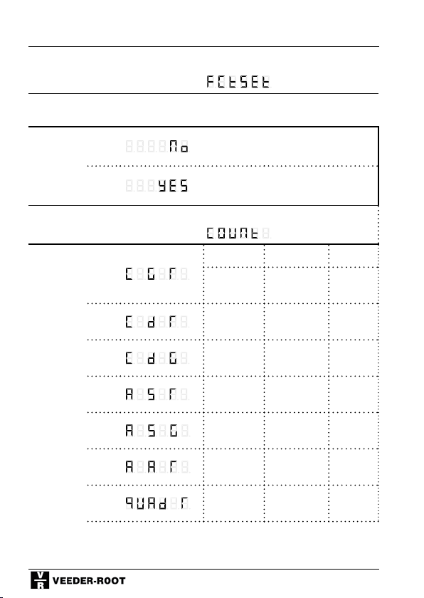
Batch Counter
Function code F0, Display Row 1:
Function No. Display Row 2
Factory
0*
Setting
(Defaults)
1
Function code F1, Display Row 1:
Counter
Mode of
Operation
0*
1
2
3
4
5
6
No function
All function codes are set to the
values marked with *
Input A Input B Input C
Count
Input
Count
Input
Count
Input
Gate Reset
Directional
input
Directional
input
Reset
Gate
Adding Subtracting Reset
Adding Subtracting Gate
Adding Adding Reset
Channel A Channel B Reset
98
Page 99
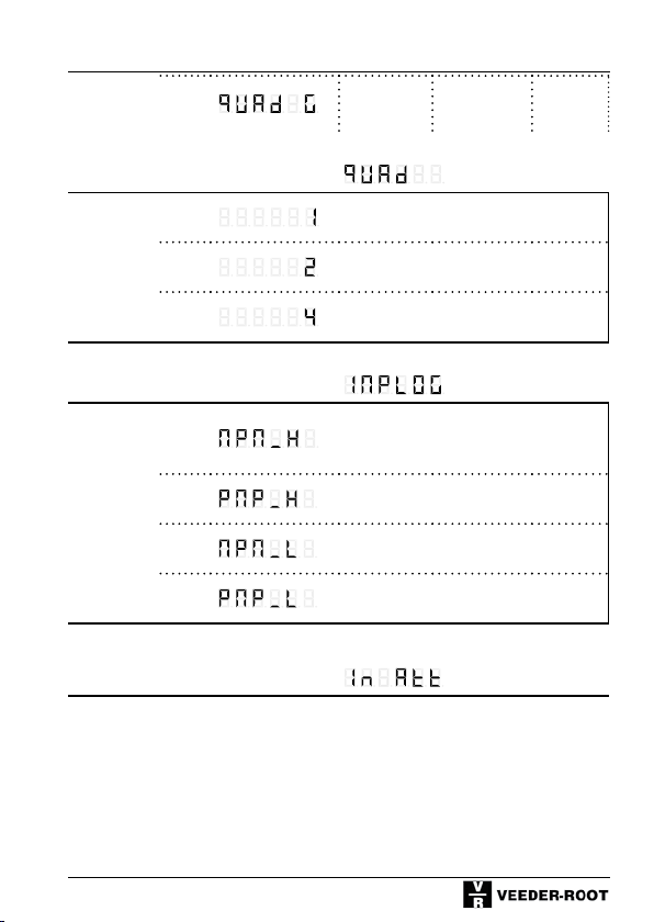
Batch Counter
7
Function code F2, Display Row 1:
Edge
Evaluation
Quadrat.
Evaluation
0*
1
2
Function code F3, Display Row 1:
PNP/
NPN-Lo-
0
gic
1*
2
3
Function code F4, Display Row 1:
Channel A Channel B Gate
Single evaluation
Double evaluation
Quadruple evaluation
NPN 8 V-Level
PNP 8 V-Level
NPN TTL-Level
PNP TTL-Level
99
Page 100
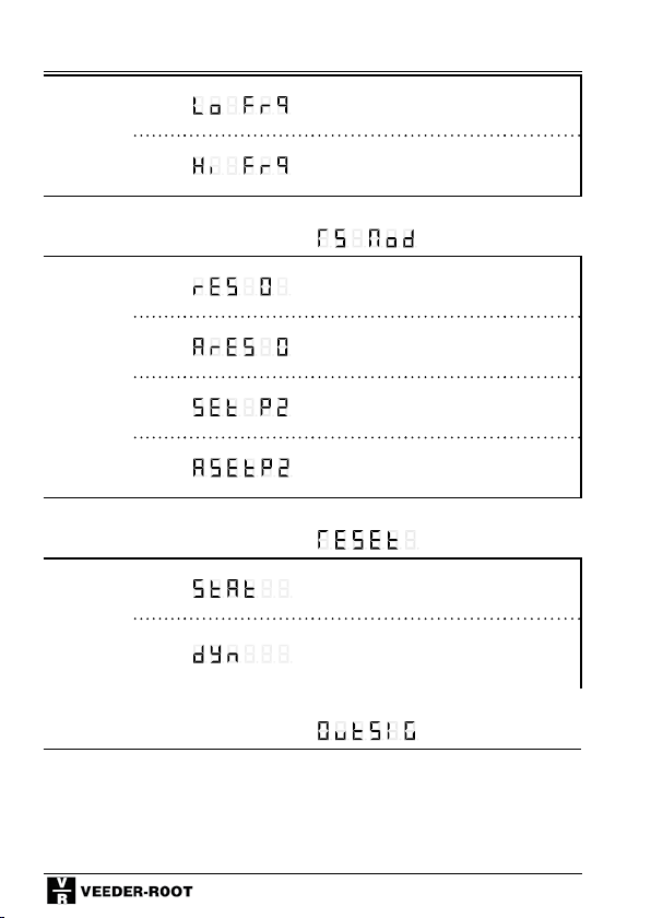
Batch Counter
Input
0
damping
(Attenuat)
1*
Function code F5, Display Row 1:
Set / Reset- Mode
0*
1
2
3
Function code F6, Display Row 1:
Dynamic/
static
Reset
0*
1
30 Hz damping (e.g. for mechanical
contacts)
F max. (see chapter 4 and 10)
Reset to 0
Automatic reset to 0 when Preset
value 2 is reached
Sets to Preset value 2
Automatic set to Preset 2 after
reaching 0
Static Reset (reset as long signal is
applied)
Dynamic Reset (ready to count after
reset, even if reset signal is applied
for a longer time)
Function code F9, Display Row 1:
100
 Loading...