

Page 1

Manual No: 577013-401 ● Revision: K
Application Guide
TLS Consoles Point-of-Sale (POS)
Page 2

Notice
Veeder-Root makes no warranty of any kind with regard to this publication, including, but not limited to, the implied warranties of
merchantability and fitness for a particular purpose.
Veeder-Root shall not be liable for errors contained herein or for incidental or consequential damages in
connection with the furnishing, performance, or use of this publication.
The information contained in this publication may be subject to change without notice.
This publication contains proprietary information which is protected by copyright. All rights reserved. No part of this publication may be
photocopied, reproduced, or translated to another language without the prior written consent of Veeder-Root.
©Veeder-Root 2018. All rights reserved
ii
.
Page 3

Introduction
Business Inventory Reconciliation (BIR) ...........................................................................1
In-Station Diagnostics (ISD) - TLS-350R Consoles Only .........................................1
TLS-350R BIR and ISD Capabilities .................................................................................1
TLS-350R with BIR only and TLS-350R with BIR and ISD ......................................1
TLS-350R with ISD only ...........................................................................................1
Manifolded Tank Applications for BIR ......................................................................1
TLS-350R System Requirements for BIR and ISD ..........................................................2
Business Inventory Reconciliation............................................................................2
In-Station Diagnostics...............................................................................................2
TLS-450/TLS-450PLUS BIR Capabilities .........................................................................2
Manifolded Tank Applications...................................................................................3
TLS-450/TLS-450PLUS System Requirements for BIR ...........................................3
Supported POS Systems ..................................................................................................3
Other Applications ....................................................................................................4
DIM Descriptions
Mechanical Dispenser Interface Module (MDIM) &
Low Voltage Dispenser Interface Module (LVDIM) ...........................................................5
Electronic Dispenser Interface Module (EDIM) .................................................................5
Current Loop Dispenser Interface Module (CDIM) ...........................................................5
LAN Dispenser Interface Module (LDIM) - TLS-350R only ...............................................5
International Forecourt Standards Forum Dispenser Interface
Module (IFSF) - TLS-350R, TLS-450PLUS ......................................................................6
TCP/IP DIM Module (TDIM) - TLS-350R ..........................................................................6
TCP/IP DIM (TDIM) - TLS-450/TLS-450PLUS .................................................................6
DIM And Installation Kit Ordering Guide ...........................................................................7
Table of Contents
DIM Installation Examples
Bennett POS System ......................................................................................................16
Veeder-Root Software Requirements.....................................................................16
Veeder-Root Hardware Requirements (Ref. Table 2) ............................................16
Bennett System Limitations ....................................................................................16
Installation Notes ....................................................................................................16
Gilbarco TCRG, TCRG2, T-11, and T-12 POS Systems ................................................18
TLS Console Software Requirements ....................................................................18
Veeder-Root Hardware Requirements (Ref. Table 2) ............................................18
Specific Limitations.................................................................................................18
Wiring Diagram for a Transac Current Loop Interface............................................19
Wiring Diagram for an Excentus Current Loop Interface ........................................20
Gilbarco TS-1000 POS and PAM Systems .....................................................................21
TLS Console Software Requirements ....................................................................21
Veeder-Root Hardware Requirements (Ref. Table 2) ............................................21
Gilbarco POS and Dispensing System Requirements ...........................................21
Specific Limitations.................................................................................................21
Wiring to a Universal Distribution Box Interface .....................................................21
Gilbarco G-Site™ POS Systems ....................................................................................23
TLS Console Software Requirements ....................................................................23
Veeder-Root Hardware Requirements (Ref. Table 2) ............................................23
Specific Limitations.................................................................................................23
Wiring Diagram.......................................................................................................23
AutoGas Storemaster and Gilbarco Dispenser Systems ................................................25
TLS Console Software Requirements ....................................................................25
Veeder-Root Hardware Requirements (Ref. Table 2) ............................................25
iii
Page 4

Table of Contents
Gilbarco POS and Dispensing System Requirements ...........................................25
System Limitations .................................................................................................25
Installation Notes ....................................................................................................25
Gilbarco SmartCrind Dispenser Systems .......................................................................30
TLS Console Software Requirements ....................................................................30
Veeder-Root Hardware Requirements (Ref. Table 2) ............................................30
System Limitations .................................................................................................30
Installation Notes ....................................................................................................30
Tokheim Dispensing Systems .........................................................................................31
TLS Console Software Requirements ....................................................................31
Veeder-Root Hardware Requirements ...................................................................31
Tokheim DHC Requirements..................................................................................31
Specific Limitations.................................................................................................31
Other POS Consoles ..............................................................................................31
Installation Notes ....................................................................................................31
Wayne Dispensing Systems ...........................................................................................34
TLS Console Software Requirements ....................................................................34
Veeder-Root Hardware Requirements ...................................................................34
POS System Requirements and Limitations ..........................................................34
Supported Wayne Systems ....................................................................................34
Supported Wayne POS Terminals .........................................................................34
Installation Notes ....................................................................................................35
Schlumberger POS Systems ..........................................................................................37
TLS Console Software Requirements ....................................................................37
Veeder-Root Hardware Requirements (Ref. Table 2) ............................................37
System Limitations .................................................................................................37
MicroMax/Allied Hardware Requirements ..............................................................37
Installation Notes ....................................................................................................37
GasBoy CFN Systems ....................................................................................................40
TLS Console Software Requirements ....................................................................40
Veeder-Root Hardware Requirements (Ref. Table 2) ............................................40
GasBoy System Requirements for BIR Interface ..................................................40
Connecting to the Site Controller II.........................................................................40
BIR Protocol DIM ............................................................................................................42
POS System Requirements and Limitations ..........................................................42
Mechanical Dispensers ...................................................................................................43
TLS-350 MDIM Applications...................................................................................43
TLS-450/TLS-450PLUS MDIM Applications...........................................................43
LVDIM Applications ........................................................................................................48
PetroVend System 2 Controller..............................................................................48
Kraus Micon 200 Electronic Dispensers.................................................................50
Wiring to GasBoy 9800 or Tokheim 2600 Series Electronic Dispensers................52
Figures
Figure 1. Simplified DIM Connections To Various Dispensing Systems ..............15
Figure 2. Bennett Pump Fuelomat Dispenser Interface Installation Diagram..........17
Figure 3. Transac Series Current Loop Interface .................................................19
Figure 4. Excentus Current Loop Interface ..........................................................20
Figure 5. Universal Distribution Box Interface ......................................................22
Figure 6. Example G-Site Installations .................................................................24
Figure 7. AutoGas 510 CRIND Controller With Current Loop Interface ...............26
Figure 8. AutoGas 510 CRIND Controller With Serial Interface ..........................27
Figure 9. AutoGas 510 CRIND Controller ............................................................28
iv
Page 5

Table of Contents
Figure 10. AutoGas 507 CRIND Controller ............................................................29
Figure 11. SmartCrind Installation .........................................................................30
Figure 12. Tokheim DHC Standalone Installation ..................................................32
Figure 13. Tokheim Vision 100/200 Installation .....................................................32
Figure 14. Tokheim Dispenser Controller With Single CAB Installation ................33
Figure 15. Wayne Dispenser Data Box Current Loop (TLS-350R and TLS-450)......35
Figure 16. Wayne IDPOS Dispensers (TLS-350R and TLS-450) ..........................35
Figure 17. Example CAB Connections In
Wayne Nucleus Data Box (TLS-350R Only) .........................................36
Figure 18. MicroMax POS W/Allied Station Site Controller Box
Current Loop Interface ..........................................................................37
Figure 19. MicroMax POS with Allied Protocol Box Current Loop Interface ..........38
Figure 20. Pro Series Or MicroMax POS With SAM Or XPIC Controller Box
And RS-232 CAB Interface ...................................................................38
Figure 21. MicroMax POS with Tokheim DCHC Controller Box and
RS-232 CAB Interface ..........................................................................39
Figure 22. Verifone With SAM And RS-232 CAB Interface ...................................39
Figure 23. Gasboy Console Loop Connection .......................................................41
Figure 24. Wiring Diagram Of TLS-350 MDIM Using Two 1871/7697 Series
Pulse Transmitters And Required Barriers ...........................................43
Figure 25. Wiring Diagram Of TLS-450/TLS-450PLUS MDIM Using
Two 1871/7697 Series Pulse Transmitters & Required Barriers..............44
Figure 26. Mechanical Dispenser Applications
Using 7874 Series Pulser/Totalizer ......................................................45
Figure 27. TLS-350 Meter Stand Application Using
1871/7697 Series Pulser/Totalizer ........................................................46
Figure 28. TLS-450/TLS-450PLUS Meter Stand Application Using
1871/7697 Series Pulser/Totalizer ........................................................47
Figure 29. TLS-350 LVDIM Installation With PetroVend
System 2 Site Controller .......................................................................48
Figure 30. TLS-450/TLS-450PLUS LVDIM Installation With
PetroVend System 2 Site Controller .....................................................49
Figure 31. TLS-350 LVDIM Installation Kraus Micon 200 Series
Electronic Dispensers (Not UL Approved) ............................................50
Figure 32. TLS-450/TLS-450PLUS LVDIM Installation
Kraus Micon 200 Series Electronic Dispensers (Not UL Approved) ........51
Figure 33. LVDIM Installation With GasBoy 9800 Or
Tokheim 2600 Series Electronic Dispenser Head ................................52
Figure 34. TLS-450/TLS-450PLUS LVDIM Installation With
GasBoy 9800 Or Tokheim 2600 Series Electronic Dispenser Head ........ 53
Tables
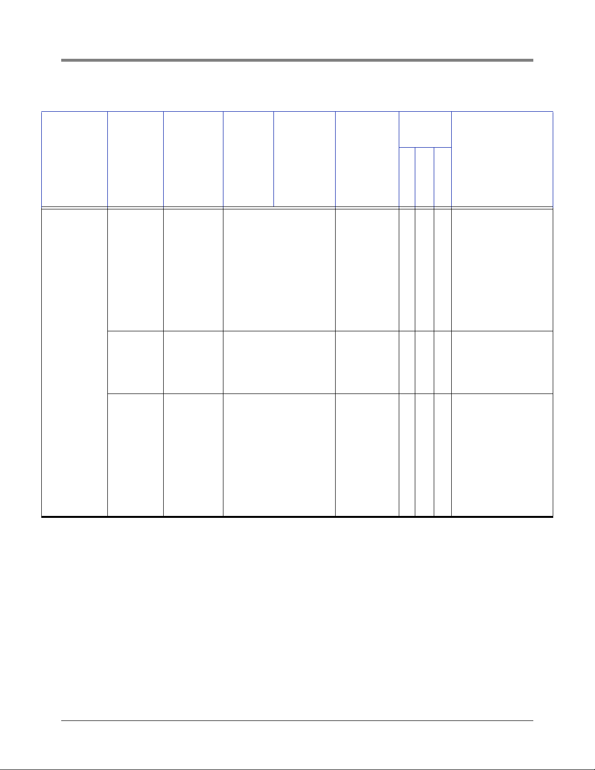
Table 1. Supported POS Systems ..........................................................................3
Table 2.- Dispenser DIM and Installation Kits ..........................................................7
Table 3. POS Systems Supporting BIR Protocol DIM ..........................................42
v
Page 6

Introduction
This guide provides assistance in selecting Dispenser Interface Modules (DIMs) that enable a properly fitted TLS
Console to interface supported Point-of-Sale (POS) devices and provide enhanced product inventory and/or
product vapor recovery monitoring. Veeder-Root offers two console upgrades that interface with POS devices:
Business Inventory Reconciliation (BIR)
Business Inventory Reconciliation is a console option that automatically collects dispensing data, in-tank
inventories and deliveries, and reconciles the totals at the end of each shift, day, and month. When used with
AccuChart™, an automatic tank calibration feature, BIR enhances reconciliation accuracy by comparing the tank’s
metered sales data to the tank’s probe data.
IN-STATION DIAGNOSTICS (ISD) - TLS-350R CONSOLES ONLY
In-Station Diagnostics (ISD) is an option that enables the TLS-350R Console to continuously monitor the vapor
recovery equipment and Enhanced Vapor Recovery (EVR) systems at gasoline dispensing facilities, maintain test
records, provide test reports, and generate warnings or alarms following equipment failures.
TLS-350R BIR and ISD Capabilities
TLS-350R WITH BIR ONLY AND TLS-350R WITH BIR AND ISD
• Support up to 36 fueling positions
• Support up to 6 meters (hoses) per fueling position
• Support manifolded tanks
• Support blending dispensers that separately meter each product prior to blending. Gilbarco, Tokheim, and
Wayne electronic blending dispensers are supported.
• Do not support dispensers that blend fuel prior to the metering process. Schlumberger electronic blending dispensers, and mechanical dispensers fitted with fixed-ratio ratios are not supported.
TLS-350R WITH ISD ONLY
• Supports up to 36 fueling positions
• Supports up to 6 meters (hoses) per fueling position
• Supports manifolded tanks
• Supports all blending dispensers in this guide, including those in this guide labeled as not to be used with BIR.
• Must monitor all petrol fueling positions.
• Does not monitor diesel fueling positions.
MANIFOLDED TANK APPLICATIONS FOR BIR
The TLS-350R can perform automatic BIR on tanks in a siphon-manifolded set. However, to perform AccuChart,
the following requirements must be met:
1. Maximum of 2 tanks in a set.
2. Maximum of 4 sets of siphon-manifolded tanks.
3. The combined tank capacity of a set shall not exceed 30,000 gallons.
4. The diameters of the tanks in a set shall not differ by more than 6 inches.
5. The manifolding method must be siphon, not line, manifolding.
1
Page 7

POS App Guide Introduction
Reconciliation reports will be generated for the manifolded set as a single product. Individual adjusted delivery
reports will be provided followed by an adjusted manifolded delivery report.
Both Version 310 software (or later), and a Memory Expansion Module are required to perform BIR for manifolded
tanks.
TLS-350R System Requirements for BIR and ISD
BUSINESS INVENTORY RECONCILIATION
• TLS-350R with BIR option
• A Mag 1 (0.1 gph) magnetostrictive (standard or Mag Plus) probe is required for each tank that will be
monitored and reconciled. The Mag 1 probe for alternative fuels is also supported.
• ECPU board with the following software versions;
- w/106 [or later] software for BIR,
- w/311 [or later] software and a Memory Expansion Module for BIR with manifolded tanks, or
- w/116 or 316 [or later] software for BIR with variance analysis
• Dispenser Interface Module
For electronic dispensers, one DIM is required for each TLS-350R. Up to 3 DIMs can be installed to support
sites with multiple POS systems. For mechanical dispensers, the TLS-350R can support up to 8 mechanical
DIMs. Each mechanical DIM supports up to 4 mechanical dispensers.
One installation kit may be required for each DIM (ref. Table , “,” on page 7). The installation kits vary for each
DIM and include all required adapter boxes and cables.
IN-STATION DIAGNOSTICS
• TLS-350R with ISD option
• ECPU2 board with 325 or later software and a NVMEM203 board.
• A Mag 1 (0.1 gph) magnetostrictive (standard or Mag Plus) probe is required for each gasoline tank. The Mag 1
probe for alternative fuels is also supported.
• Dispenser Interface Module - For electronic dispensers, one DIM is required for each TLS-350R. Up to 3 DIMs
can be installed to support sites with multiple POS systems. For mechanical dispensers, the TLS-350R can
support up to 8 mechanical DIMs. Each mechanical DIM supports up to 4 mechanical dispensers.
• DIM installation kit - One installation kit may be required for each DIM (ref. Table , “,” on page 7). The installation
kits vary for each DIM and include all required adapter boxes and cables.
• Additional ISD monitoring equipment as defined by the site’s requirements, e.g., dispenser mounted Air Flow
Meters and Pressure Sensor, console Smart Sensor Modules, etc. - refer to appropriate ISD Installation Manual
for specifics.
TLS-450/TLS-450PLUS BIR Capabilities
• Support for up to 72 fueling positions
• Support for up to 6 meters (hoses) per fueling position
• Support for manifolded tanks
• Support for blending dispensers that separately meter each product prior to blending. Gilbarco, Tokheim, and
Wayne electronic blending dispensers are supported. Dispensers that blend fuel prior to the metering process,
2
Page 8

POS App Guide Introduction
such as Schlumberger electronic blending dispensers and mechanical dispensers fitted with fixed-ratio blenders
are not supported.
MANIFOLDED TANK APPLICATIONS
• Maximum number of tanks in a set: unlimited
• Maximum number of siphon manifold tanks: number of tanks divided by 2. Limit: 8
• Manifolded set tank capacity: unlimited
• No requirements on diameter differences, no 6 inch limit.
Reconciliation reports will be generated for the manifolded set as a single product. Individual adjusted delivery
reports will be provided followed by an adjusted manifolded delivery report.
TLS-450/TLS-450PLUS SYSTEM REQUIREMENTS FOR BIR
The following components are required to perform BIR:
• TLS-450/TLS-450PLUS with BIR option
• Version 2.X or higher software (TLS-450), Version 6.X or higher software (TLS-450PLUS)
• Mag 1 (0.1 gph) magnetostrictive (standard or Mag Plus) probe in each tank. The Mag 1 probe for alternative
fuels is also supported.
• A Dispenser Interface Module (DIM) - The DIM allows the TLS-450 to interface to most Gilbarco, Wayne, and
3rd Party POS systems that implement the VR BIR Protocol (ALLIED ANDI, EXCENTUS, BENNETT). For
electronic dispensers, one DIM is required for each TLS-450. Up to 3 DIMs can be installed to support sites
with multiple POS systems.
• DIM installation kit - One installation kit may be required for each DIM (ref. Table , “,” on page 7). The installation
kits vary for each DIM and include all required adapter boxes and cables.
Supported POS Systems
The TLS-350R, TLS-450 and TLS-450PLUS consoles can interface to many POS terminals as well as the VeederRoot mechanical dispenser (TLS-350R only). This guide provides specific information on each application. The
supported POS systems are shown in
Manufacturer POS/Dispensing System TLS-350R TLS-450 TLS-450PLUS
TCRG, TCRG2, T-11, T-12, TS-1000, PAM,
Gilbarco
Tokheim
Wayne
G-Site, Passport, Storemaster, SmartCrind, ANDI,
CFN2, Excentus
MEMS IV, MEMS V, Vision 100/200, DHC with all
other POS, CFN2, ANDI, Columbus, Schlumberger
MicroMax XPIC/DHC, 67/A - 98, 67/B
Wayne Site Controller, Excentus, ANDI X X X
IDPOS X X X
Table 1.
Table 1. Supported POS Systems
X X X
X
Schlumberger
GasBoy CFN2 & ProfitPoint, CFN1, ANDI X
MicroMax/Pro series, MicroMax/Allied, SAM/XPIC,
ANDI
3
X
Page 9

POS App Guide Introduction
Table 1. Supported POS Systems (Continued)
Manufacturer POS/Dispensing System TLS-350R TLS-450 TLS-450PLUS
Bennett 92D X
Mechanical, Mechanical
noncomp, or Mechanical
V-R meter
CFN2, Petrovend, ANDI X X X
OTHER APPLICATIONS
Many POS / dispenser systems are similar to those identified in this guide. Veeder-Root is constantly evaluating
and supporting new applications. If your application is not listed in this guide, contact your Veeder-Root Sales
Representative.
4
Page 10

DIM Descriptions
Mechanical Dispenser Interface Module (MDIM) & Low Voltage Dispenser Interface
Module (LVDIM)
• The mechanical dispenser interface modules enable the TLS console to monitor either high voltage (MDIM), or
low voltage (LVDIM) volume pulses and calculate dispensed volume.
• MDIM and LVDIM terminal connections are on the front of the modules’s bracket.
Electronic Dispenser Interface Module (EDIM)
• Installs in a communication slot of TLS-350R or TLS-450/TLS-450PLUS. EDIMs are used to communicate via
RS-232 to point of sale or system controllers.
• More than one EDIM can be installed in any combination with other DIM types.
• EDIMs have one 25-pin D connector (TLS-350R), or one 9-pin D connector (TLS-450/TLS-450PLUS) outside
of the port.
• TLS-350R EDIMs only - when onboard red LED is turned On, EDIM is transmitting to external device; when
onboard green LED is turned On, external device is transmitting to EDIM.
• TLS-450 and TLS-450PLUS hardware is standard equipment.
• TLS-450 requires BIR to activate DIM.
Current Loop Dispenser Interface Module (CDIM)
• TLS-350R console - Installs in comm slots 1, 2, or 3; TLS-450 console - installs in comm slots 1, 2, or 4
(preferred); TLS-450PLUS console - installs in comm slots 1 or 2. Factory installed in TLS4 console.
• TLS-450 and TLS-450PLUS require module kit P/N 330020-665.
• Various CDIM monitoring applications include current loop, RS-232, and RS-422.
• More than one CDIM can be installed in combination with other DIM types.
• CDIMs have three RJ-45 modular connectors (TLS-350R) or 2 to 3 RJ-45 modular connectors (TLS-450/TLS-
450PLUS).
• CDIMs cannot transmit to external device.
• Connects via 4-wire cable to cable adapter box. Adapter box converts target communication format to RS-422
format for CDIM. Adapter boxes are configured with 2-wire flying leads, 25-pin D or 9-Pin D, T-cable connectors
for various applications.
• TLS-450 requires BIR to activate DIM.
LAN Dispenser Interface Module (LDIM) - TLS-350R only
• Installs in a communication port of TLS-350R to communicate with or monitor POSs, dispensers or system
controllers using RS-485 communication standard.
• An LDIM can be installed in combination with other DIM types.
• LDIMs have a 5-wire phoenix connector.
• Red and green LEDs are on this board. When red LED is turned On, LDIM is transmitting to external device;
when green LED is turned On, external device is transmitting to LDIM.
• Can be used in 4-wire or 2-wire, RS-485 and RS-422 applications.
- DIP switch default in OPEN position, loopback jumper on LED side for RUN mode
- R1 - 331076-001 - RS-485 two wire
5
Page 11

POS App Guide DIM Descriptions
- R2 - 331076-002 - RS-422 four wire
- R3 - 331076-003 - DIM RS-485 two wire (install in TLS-350R only)
- R4 - 331076-004 - DIM RS-422 four wire (install in TLS-350R only)
International Forecourt Standards Forum Dispenser Interface Module (IFSF) - TLS350R, TLS-450PLUS
• Required for TLS consoles that are connected to IFSF networks.
• Uses Echelon 2-wire FTT10-A medium, as defined by the IFSF standards.
• There are 3 LEDs on this board:
- Green LED On when IFSF board is transmitting information to the TLS.
- Red LED On when TLS is transmitting information to the IFSF board.
- Amber LED Off indicates normal state of the IFSF board processor.
• There are no LED indicators for network communication.
TCP/IP DIM Module (TDIM) - TLS-350R
• Installs in a communication port of the TLS-350R to communicate with or monitor the Wayne IDPOS dispenser.
• Minimum system requirements for TDIM Module operation:
- Console system software: Version 15 or higher - Version 21 or higher is recommended
- Network connection to a PC requires a hub. Connecting to a hub requires a straight CAT 5 cable
- Direct connection to a PC requires an Ethernet crossover cable
- Connection to a LAN or WAN
• There are 2 LEDs on the PC board of this module:
- Green LED indicates that the TDIM module is transmitting information to the TLS.
- Red LED indicates the TLS is transmitting information to the TDIM module.
• There is no communication alarm for this module.
TCP/IP DIM (TDIM) - TLS-450/TLS-450PLUS
• Installs in a communication port of the TLS-450/TLS-450PLUS to communicate with or monitor the Wayne
IDPOS dispenser.
• Minimum system requirements for TDIM module operation:
- Console system software: Version 4H or higher
- Network connection to a PC requires a hub. Connecting to a hub requires a straight CAT 5 cable
- Direct connection to a PC requires an Ethernet crossover cable
- Connection to a LAN or WAN
• There is no communication alarm for this module.
• TLS-450 and TLS-450PLUS hardware is standard equipment.
• TLS-450 requires BIR to activate DIM.
6
Page 12
POS App Guide DIM Descriptions
DIM And Installation Kit Ordering Guide
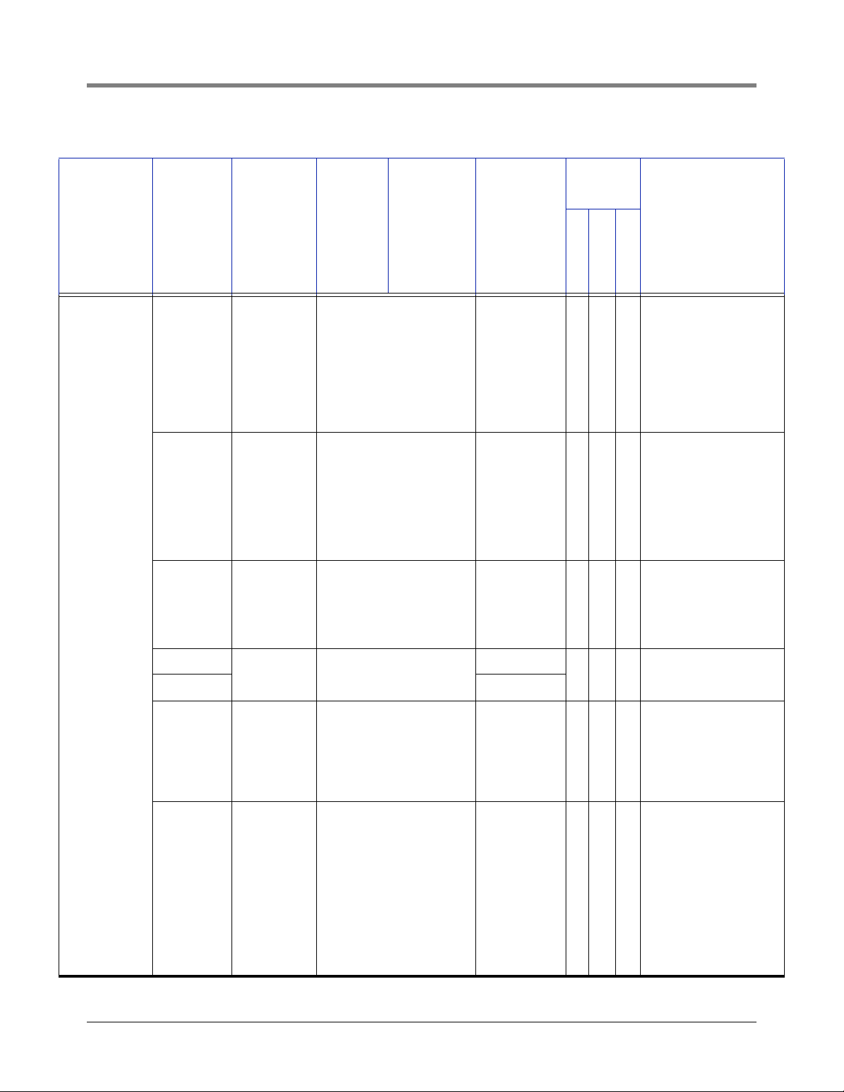
Table 2.- Dispenser DIM and Installation Kits
Console
Compati-
bility
Dispenser
Dispenser
Bennett 92D 330404-040 None 848705-XXX Y N N
Gasboy
Controller/
POS Type
CFN2 &
Profit Point
ANDI,
ALLIED
ANDI,
ALLIED
NEXTGEN
CFN1 331001-002 None 331088-XXX Y N N
TLS-350R
DIM P/N
w/Console
331001-003 None 331088-XXX Y N N
330280-001 Standard In Gauge
TLS-450
DIM P/N
w/Console
TLS-450PLUS
DIM P/N
w/Console
DIM Install Kit
P/N
None
required
TLS-350R
TLS-450
Y Y Y
TLS-450PLUS
For Bennett 92D controllers. DIM kit has 2
CABs in it. One CAB is
needed per current
loop. Only one or two
dispensers are on one
current loop.
A Gasboy site controller version 2.0 or later
is required. A Gasboy
junction box Gasboy
part # C05020 should
be ordered for installation. No Blending. Network POS Required.
Allied ANDI. Gilbarco
dispenser with T-14
(Australia). PEC with
8850. POSTEC with
RCC. Wayne with Marketer 2000 (Sweden).
This is a TLS-350 RS422 interface to the
Network. NOT to be
used for BIR or ISD
applications.
Notes
Radiant 330280-001 Standard In Gauge
7
None
required
Y Y Y
Radiant Systems
Series P1550 set-up
on the TLS must have
a DIM string programmed in. The DIM
string is B9DNHG and
needs to be programmed in DIM Diagnostics. You will need
to use a twisted pair
RJ-11 cable to the port
on the POS with the
pin outs of 2,3,7.
Page 13
POS App Guide DIM Descriptions
Table 2.- Dispenser DIM and Installation Kits
Console
Compati-
bility
Dispenser
Gilbarco
Dispenser
Controller/
POS Type
TCRG
TLS-350R
DIM P/N
w/Console
TLS-450
DIM P/N
w/Console
TLS-450PLUS
DIM P/N
w/Console
DIM Install Kit
P/N
TLS-350R
TLS-450
Y Y Y
TCRG2 Y Y Y
T-11 Y Y Y
330404-020 330020-665 848702-XXX
T-12 Y Y Y
Excentus Y Y Y
TS-1000
Y Y Y One kit is needed per
330404-020 330020-665 848722-XXX
PAM Y Y Y
G-Site
Y Y Y
330280-401 Standard In Gauge 331063-XXX
TLS-450PLUS
Notes
Model TCRG
PA0180-121
Model TCRG2
PA0180-121
Model T-11 PA0132XXXX and PA0141XXXX
Model T-12 PA0188XXXX
Excentus Dispenser
Tank Monitor Interface
Kit (Excentus P/N 080Veeder Root Kit) is
required.
dispenser current loop.
For controller with a
RS-485 Distribution
Box, use kit P/N
848741-XXX.
To support this DIM
and the TLS-350R, the
G-site must be
upgraded to include
the EMC interface.
Uses Controller types
C2, C15, 486 and Pentium Site controllers.
Passport,
Passport/
EDH
Storemaster
Y Y Y
330404-020 330020-665 848741-XXX Y Y Y
8
Verify BIR protocol is in
version of Passport
software used at customer’s site.
One Gilbarco Dispenser Distribution Box
PA0133000 should be
available. Up to 12
Highliner/MPD Fueling
positions are supported. An Autogas
Storemaster POS and
Autogas 507 controller
are required.
Page 14
POS App Guide DIM Descriptions
Table 2.- Dispenser DIM and Installation Kits
Console
Compati-
bility
Dispenser
Gilbarco
(Cont’d.)
Dispenser
Controller/
POS Type
SmartCrind
TLS-350R
DIM P/N
w/Console
330020-538
TLS-450
DIM P/N
w/Console
TLS-450PLUS
DIM P/N
w/Console
DIM Install Kit
P/N
None
required
TLS-350R
TLS-450
Y Y Y
Standard In Gauge
ANDI,
ALLIED
ANDI,
ALLIED
330280-001
None
required
Y Y Y
NEXTGEN
CFN2 331001-003 None 331088-XXX Y N N
Wayne
Nucleus
330404-200 330020-665 848722-XXX Y Y Y
TLS-450PLUS
Notes
TCPIP Interface for Gilbarco SmartCrind dispensers only. Wal-Mart
is currently the only
customer ordering this
interface for this dispenser.
Allied ANDI. Gilbarco
dispensers with T-14
(Australia). PEC with
8850. POSTEC with
RCC. Wayne with Marketer 2000 (Sweden)
A Gasboy site controller version 2.0 or later
is required. A Gasboy
junction box Gasboy
part # C05020 should
be ordered for installation. Single product
dispensers only. No
Blending.
Wayne Nucleus POS
with Gilbarco Dispensers.
Radiant 330280-001
Verifone
Com-
330280-001 None Y Y Y
mander
Wayne
Fusion
330280-001 None None Y N N
Standard In Gauge
9
None Y Y Y
Radiant Systems
Series P1550 set-up
on the TLS must have
a DIM string programmed in. The DIM
string is B9DNHG and
needs to be programmed in DIM Diagnostics. You will need
to use a twisted pair
RJ-11 cable to the port
on the POS with the
pin outs of 2,3,7.
Requires Verifone
13652-01 Connector(450) or Verifone
13581-01 Connector
(350) & V/R 331134xxx cable.
Page 15
POS App Guide DIM Descriptions
Table 2.- Dispenser DIM and Installation Kits
Console
Compati-
bility
Dispenser
Dispenser
Controller/
POS Type
TLS-350R
DIM P/N
w/Console
TLS-450
DIM P/N
w/Console
TLS-450PLUS
DIM P/N
w/Console
DIM Install Kit
P/N
TLS-350R
TLS-450
Mechanical CFN2 331001-003 None 331088-XXX Y Y Y
Mechanical
Mechanical
non-comp, or
Petrovend 331214-001 330020-800 None Y Y Y
Mechanical
V-R meter
TLS-450PLUS
Notes
A Gasboy site controller version 2.0 or later
is required. A Gasboy
junction box Gasboy
part # C05020 should
be ordered for installation. Single product
dispensers only. No
Blending. Network
POS required.
One or more pulser/
totalizer kits are
needed PN 787491-
003. Each mech DIM
supports up to 4 mech
dispensers. Up to 8
may be installed in the
high power compartment of the TLS-350R.
Other modules
installed will reduce the
number of slots available.
10
Page 16
POS App Guide DIM Descriptions
Table 2.- Dispenser DIM and Installation Kits
Console
Compati-
bility
Dispenser
Mechanical
Dispenser
Controller/
POS Type
TLS-350R
DIM P/N
w/Console
TLS-450
DIM P/N
w/Console
TLS-450PLUS
DIM P/N
w/Console
DIM Install Kit
P/N
TLS-350R
TLS-450
None 331214-001 330020-800 None Y Y Y
ANDI 330280-001 Standard In Gauge None Y Y Y
Radiant 330280-001 Standard In Gauge None Y Y Y
TLS-450PLUS
Notes
One or more pulser/
totalizer kits are
needed PN 787491-
003. Each mech DIM
supports up to 4 mech
dispensers. Up to 8
may be installed in the
high power compartment of the TLS-350R.
Other modules
installed will reduce the
number of slots available.
Allied ANDI. Gilbarco
dispensers with T-14
(Australia). PEC with
8850.POSTEC with
RCC. Wayne with Marketer 2000 (Sweden).
Radiant Systems
Series P1550 set-up
on the TLS must have
a DIM string programmed in. The DIM
string is B9DNHG and
needs to be programmed in DIM Diagnostics. You will need
to use a twisted pair
RJ-11 cable to the port
on the POS with the
pin outs of 2,3,7.
11
Page 17

POS App Guide DIM Descriptions
Table 2.- Dispenser DIM and Installation Kits
Console
Compati-
bility
Dispenser
Schlumberger
Dispenser
Controller/
POS Type
TLS-350R
DIM P/N
w/Console
TLS-450
DIM P/N
w/Console
TLS-450PLUS
DIM P/N
w/Console
DIM Install Kit
P/N
TLS-350R
TLS-450
ANDI,
ALLIED
ANDI,
330280-001 Standard In Gauge None Y Y Y
ALLIED
NEXTGEN
Radiant 330280-001 Standard In Gauge None Y Y Y
TLS-450PLUS
Notes
Allied ANDI. Gilbarco
with T-14 (Australia).
PEC with 8850. POSTEC with RCC. Wayne
with Marketer 2000
(Sweden).
Radiant Systems
Series P1550 set-up
on the TLS must have
a DIM string programmed in. The DIM
string is B9DNHG and
needs to be programmed in DIM Diagnostics. You will need
to use a twisted pair
RJ-11 cable to the port
on the POS with the
pin outs of 2,3,7.
12
Page 18
POS App Guide DIM Descriptions
Table 2.- Dispenser DIM and Installation Kits
Console
Compati-
bility
Dispenser
Tokheim
Dispenser
Controller/
POS Type
TLS-350R
DIM P/N
w/Console
TLS-450
DIM P/N
w/Console
TLS-450PLUS
DIM P/N
w/Console
DIM Install Kit
P/N
TLS-350R
TLS-450
MEMS IV,
MEMS V,
Vision 100/
200,
330280-201 None 331390-XXX Y N N
DHC with
all other
POS
CFN2 331001-003 None 331088-XXX Y N N
ANDI,
ALLIED
ANDI,
330280-001 Standard In Gauge None Y Y Y
ALLIED
NEXTGEN
TLS-450PLUS
Notes
Use 331354-001 for
67A/B or 98 instead.
This DIM is being
phased out. A Tokheim
Dedicated Hose Controller (DHC) is
required, and should
have software version
5.6 dated 11/89 or
later.
A Gasboy site controller version 2.0 or later
is required. A Gasboy
junction box Gasboy
part # C05020 should
be ordered for installation. Single product
dispensers only. No
Blending
1
Allied ANDI. Gilbarco
dispenser with T-14
(Australia). PEC with
8850. POSTEC with
RCC. Wayne with Marketer 2000 (Sweden).
67/A - 98
331354-001 None
331391-XXX
Y N N
67/B 848744-XXX
Columbus 330280-001 Standard in Gauge None Y Y Y
Radiant 330280-001 Standard in Gauge None Y Y Y
13
Tokheim controller
only.
For Rockport cable kits
order Quantity (2)
320449-18 from
Tokheim. For Digi/Stargate order Quantity (2)
320449-9 Cable kits
from Tokheim.
Radiant Systems
Series P1550 set-up
on the TLS must have
a DIM string programmed in. The DIM
string is B9DNHG and
needs to be programmed in DIM Diagnostics. You will need
to use a twisted pair
RJ-11 cable to the port
on the POS with the
pin outs of 2,3,7.
Page 19

POS App Guide DIM Descriptions
Table 2.- Dispenser DIM and Installation Kits
Console
Compati-
bility
Dispenser
Wayne
Dispenser
Controller/
POS Type
Wayne Site
Controller
TLS-350R
DIM P/N
w/Console
TLS-450
DIM P/N
w/Console
TLS-450PLUS
DIM P/N
w/Console
DIM Install Kit
P/N
TLS-350R
TLS-450
330404-010 330020-665 848703-XXX Y Y Y
ANDI,
ALLIED
ANDI,
330280-001 Standard in Gauge None Y Y Y
ALLIED
NEXTGEN
Excentus 330404-010 330020-665 848702-XXX Y Y Y
IDPOS 330020-501 Standard in Gauge None Y Y Y
Radiant 330280-001 Standard in Gauge None Y Y Y
TLS-450PLUS
Notes
A Wayne site controller
and Wayne dispensers are required. Any
POS may be connected to the Wayne
site controller.
Allied ANDI. Gilbarco
dispenser with T-14
(Australia). PEC with
8850. POSTEC with
RCC. Wayne with Marketer 2000 (Sweden).
Excentus Dispenser
Tank Monitor Interface
Kit (Excentus P/N 080Veeder Root Kit) is
required.
TCPIP interface for
Wayne IDPOS dispensers only
Radiant Systems
Series P1550 set-up
on the TLS must have
a DIM string programmed in. The DIM
string is B9DNHG and
needs to be programmed in DIM Diagnostics. You will need
to use a twisted pair
RJ-11 cable to the port
on the POS with the
pin outs of 2,3,7.
Verifone
Com-
330280-001 None None Y N N
mander
Wayne
Fusion
1
This restriction does not apply to ISD only installations.
330280-001 None None Y N N
14
Page 20

DIM Installation Examples
Mechanical
Dispenser
Dispenser
Controller
Network
Junction
Box
Distribution Box
Cable Adaptor
Box
CDIM
LVDIM
MDIM
EDIM
LDIM, IFSF,
& TDIM
Dispenser
Dispenser
Electronic
or
Mechanical
Dispenser
Comm Bay
installed DIMs
TLS-350 Power Bay installed DIMs
TLS-450 Model Bay installed DIMs
Barrier
401-6.eps
TLS Console
(TLS-350 only)
Various example DIM installation diagrams are shown in Figure 1 below for reference only. For specific DIM
installation details, refer to the appropriate Veeder-Root DIM installation manual.
Figure 1. Simplified DIM Connections To Various Dispensing Systems
15
Page 21

POS App Guide DIM Installation Examples
Bennett POS System
The information collected via the interface allows TLS-350R business inventory reconciliation to compare tank
totals to fuel transactions for end of day, end of shift, or end of month, running variances.
VEEDER-ROOT SOFTWARE REQUIREMENTS
• System software Version 17 (or higher)
• Peripheral controller software 330269-00B (or later)
• DIM software 349780-001A (or later)
VEEDER-ROOT HARDWARE REQUIREMENTS (REF. TABLE 2)
The following equipment is required to interface the TLS to the Bennett POS system:
• One Bennett Current Loop Dispenser Interface Module for up to 6 fueling positions
• One installation kit (for every 2 current loops (up to 12 fueling positions)
BENNETT SYSTEM LIMITATIONS
TLS-350R with BIR and TLS-350R with BIR and ISD
• Only non-blending, type 92D dispensers with Orpak controllers are supported.
TLS-350R with ISD
• All type 92D dispensers with Orpak controllers are supported.
INSTALLATION NOTES
The interface to Bennett dispensing equipment requires one CAB per dispenser current loop (for up to 6 fueling
positions) and one Bennett DIM installation kit for every 2 current loops. Typically one or two loops are required for
a single dispenser having two fueling positions. For this reason the interface kit includes two CABs with
supportivecabling. Supportive cabling required is sold in lengths, which are identified in the last three digits of the
kit form number. The length requirement is determined by the distance between the components.
Figure 2 is an example Bennett dispenser connection diagram. Each CAB has a three position input and a RJ-45
cable output to a dispenser loop. Use the “PUMP COMM” input side and the RJ-45 cable output.
16
Page 22

POS App Guide DIM Installation Examples
{
{
0
1
ALARM
WARNING
POWER
TLS-350R Console
CDIM
RJ-45
BENNETT PUMP
INTERFACE BOX
Dispenser
Terminal
Block
Communications Cable
GRN GROUND
RJ-45
Communications Cable
CONSOLE
COMM
Cable Adapter Box
for Bennett System
CURRENT LOOPS
ORG DATA (+)
17123 456 78 9111213 14 15 18 19 20 21
YEL DATA (-)
ORG DATA (+)
YEL DATA (-)
PUMP
COMM
PUMP
COMM
White
Black
Shield
CONSOLE
COMM
White
Black
Shield
2216
Cable Adapter Box
for Bennett System
Shielded 2 Wire
Flying Lead Cable
6 feet
401-7.eps
shield
GRN
Disconnect orange wire (+) from terminal 17 and
connect to white wire (+) from CAB with wire nut.
Attach black wire (-) from CAB to terminal 17. Connect
cable shield to terminal block ground connection.
Figure 2. Bennett Pump Fuelomat Dispenser Interface Installation Diagram
shield
CONDUIT
Disconnect orange wire (+) from terminal 19 and connect to
white wire (+) from CAB with wire nut. Attach black wire (-)
from CAB to terminal 17. Connect cable shield to terminal
block ground connection.
17
Page 23

POS App Guide DIM Installation Examples
Gilbarco TCRG, TCRG2, T-11, and T-12 POS Systems
TLS CONSOLE SOFTWARE REQUIREMENTS
TLS-350R with BIR Software Requirements
• System software Version 17 (or higher)
• Peripheral controller software 002B (or later)
• DIM software 349634-003C (or later)
TLS-450/TLS-450PLUS with BIR Software Requirements
• TLS-450 System software Version 2.x (or higher)
• TLS-450PLUS System software Version 6.x (or higher)
• BIR option required (TLS-450)
VEEDER-ROOT HARDWARE REQUIREMENTS (REF. TABLE 2)
The following equipment is required to interface the TLS to the Transac POS:
• One Gilbarco Current Loop Dispenser Interface Module for up to 3 current loops
• One Gilbarco dispenser distribution box PA0133000
• One Gilbarco Transac DIM installation kit required per current loop. Up to 16 fueling positions are supported
per current loop.
The following POS consoles are supported:
• Transac-1e1 (PA0132, PA0141)
• Transac-12 (PA0134, PA0142)
• Transac-12A (PA0151, PA0152)
• Transac-12B (PA0173)
• Transac-12C (PA0188)
• Transac-12G (PA0203)
• TCRG (PA0180-121)
• TCRG2 (PA0180-121)
• Excentus Reward Fuel Controller
TM
, Gilbarco Dispenser Interface, V1.0.160
SPECIFIC LIMITATIONS
Only Gilbarco electronic dispensers are supported. Also, dispensers that feature a blender and a single-product
dispenser at one fueling position are not supported.
In-Dispenser credit card readers (CRINDS) or G-Site systems are not supported by the Gilbarco CDIM.
Other POS systems that use Gilbarco dispensers and the Gilbarco Pump Access Module (PAM) may also be
supported - contact Veeder-Root for assistance.
Special Note on T-11/T-12 Pre-Pay Applications
In T-11/T-12 Pre-Pay applications, cashiers should be urged to close out each transaction promptly. Failure to
close-out promptly can cause the TLS-350R to delay reconciliation reports, and impact the system’s ability to
maximize tank calibration.
18
Page 24

POS App Guide DIM Installation Examples
Shielded 2 Wire
Flying Lead Cable
Connects to
CDIM
TLS Console
401-8.eps
WIRING DIAGRAM FOR A TRANSAC CURRENT LOOP INTERFACE
A PA0133 distribution box is shown in Figure 3 below. Other box models are slightly different.
Figure 3. Transac Series Current Loop Interface
19
Page 25

POS App Guide DIM Installation Examples
WIRING DIAGRAM FOR AN EXCENTUS CURRENT LOOP INTERFACE
These cables and terminal
block supplied by Excentus
+
WHT +
BLK -
RJ-45
Set sw
to RUN
VR 6-foot, 2-conductor
1
DIM Assembly Cable
(P/N 331105-001)
VR CAB
2
(P/N 330591-00X)
CONSOLE
COMM.
RUN
BYPASS
VEEDER-ROOT
Environmental Products
P/N
S/N
PUMP
COMM.
POS/Controller
RJ-45
RJ-45
Excentus Interface Box
Tank
Console
Dbox
Monitor
RJ-45
RJ-45
RJ-45
WHT +
BLK -
401-9.eps
Gilbarco
Distribution Box
Figure 4. Excentus Current Loop Interface
VR CDIM
3
Adaptor Cable
(P/N 330592-XXX)
3 numbered items
contained in V-R kit
(P/N 848702-XXX)
RJ-45
TLS Console
Connects to CDIM
20
Page 26

POS App Guide DIM Installation Examples
Gilbarco TS-1000 POS and PAM Systems
The Veeder-Root Gilbarco TS-1000 DIM and DIM installation kit supports the Gilbarco TS-1000 and any POS
system using the Gilbarco PAM (Pump Access Module) dispenser controller and Gilbarco dispensers.
TLS CONSOLE SOFTWARE REQUIREMENTS
TLS-350R with BIR Software Requirements
• System software Version 17 (or higher)
• DIM software 349634-003C (or later)
TLS-450/TLS-450PLUS with BIR Software Requirements
• TLS-450 System software Version 2.x (or higher)
• TLS-450PLUS System software Version 6.x (or higher)
• BIR option required (TLS-450)
VEEDER-ROOT HARDWARE REQUIREMENTS (REF. TABLE 2)
The following equipment is required to interface the TLS to the TS-1000 POS:
• One Gilbarco Current Loop Dispenser Interface Module for up to 3 current loops
• One installation kit for each current loop
GILBARCO POS AND DISPENSING SYSTEM REQUIREMENTS
• Gilbarco dispenser distribution box, PA02420000000
• Gilbarco dispenser distribution box, PA02610000010
• Gilbarco dispenser distribution box, PA02610000020
• Gilbarco pump controller, model PA02410000000
• Gilbarco Transac System 1000 Console, model PA0240000000
• Gilbarco Transac System 1000 Console, model PA02400001010
• Excentus Reward Fuel Controller™, Gilbarco Dispenser Interface, V1.0.160 (Excentus P/N 080 - Veeder Root
Kit) is required.
SPECIFIC LIMITATIONS
• Up to 48 Gilbarco single product or blending dispenser fueling positions are supported. Dispensers that feature
a blender and a single-product dispenser at one fueling position are not supported.
• Only Gilbarco dispensers are supported.
• In-dispenser credit card readers in these POS systems are not supported by the Gilbarco Current Loop Dispenser Interface Module.
• The Gilbarco Current Loop Dispenser Interface Module does not support Gilbarco G-Site applications.
WIRING TO A UNIVERSAL DISTRIBUTION BOX INTERFACE
The diagram in Figure 5 is a typical interconnection diagram for a PAM or Transac System 1000 interface (a
PA0261 distribution box is shown, the PA0241 is slightly different).
21
Page 27

POS App Guide DIM Installation Examples
PAM or Transac 1000 Site Controller
cab&dim\vrgbts.eps
CDIM
connection
TLS Console
401-10.eps
Figure 5. Universal Distribution Box Interface
22
Page 28

POS App Guide DIM Installation Examples
Gilbarco G-Site™ POS Systems
TLS CONSOLE SOFTWARE REQUIREMENTS
TLS-350R with BIR Software Requirements
• System software Version 17 (or higher)
• DIM software 349634-003C (or later)
TLS-450/TLS-450PLUS with BIR Software Requirements
• TLS-450 System software Version 2.x (or higher)
• TLS-450PLUS System software Version 6.x (or higher)
• BIR option required (TLS-450)
VEEDER-ROOT HARDWARE REQUIREMENTS (REF. TABLE 2)
The following equipment is required to interface the TLS to the G-Site POS:
• One Gilbarco Interface Module
• One installation kit for each current loop
SPECIFIC LIMITATIONS
Up to 36 Gilbarco Uni-Hose/MPD fueling positions are supported by the TLS-350R, and up to 72 fueling
positions are supported by the TLS-450/TLS-450PLUS.
In-dispenser credit card readers (CRINDS) are supported.
To support a DIM and the TLS-350R, the G-Site must be upgraded to include EMC interface capability. This has
been released in the following G-Site versions (EMC Interface capability will be released into the Generic G-Site
version 6):
• Exxon - version 25.0.243
• Shell - version 33.1.23
•Chevron Canada - version 8.1.10
The 331063-xxx installation kit contains two gender mender adapters. One gender mender is used for PC G-SITE
applications while both are used for C-2 G-SITEs
. The gender mender adapters are not identical. As shown in
Figure 6, be sure to use the correct part at the connection points for your particular installation.
WIRING DIAGRAM
G-Site wiring examples are shown in Figure 6 below:
23
Page 29

POS App Guide DIM Installation Examples
Tank
Gauge
25 pin D / RJ-45 Adapter
(Q13180-03/331138-001)
PC G-SITE
RJ45 Modular Cable
Connects
to EDIM
Connects
to EDIM
25 pin D / RJ-45 Adapter
(Q13180-03/331138-001)
G-Site
C-2 G-SITE
Tank
Gauge
Connect RJ-45 plug into
25 pin D / RJ-45 Adapter (331138-002)
Connect RJ-45 plug into
25 pin D / RJ-45 Adapter (331138-001)
Connect RJ-45 plug into
25 pin D / RJ-45 Adapter (331138-001)
Connect 25 pin D / RJ-45 Adapter (331138-002)
to Tank Guage port
RJ45 Modular Cable
Diagram A
Diagram B
Connect RJ-45 plug
directly to Tank Mon port
TLS Console
TLS Console
401-11.eps
Figure 6. Example G-Site Installations
24
Page 30

POS App Guide DIM Installation Examples
AutoGas Storemaster and Gilbarco Dispenser Systems
TLS CONSOLE SOFTWARE REQUIREMENTS
TLS-350R with BIR Software Requirements
• System software Version 17 (or higher)
• DIM software 349634-003C (or later)
TLS-450/TLS-450PLUS with BIR Software Requirements
• TLS-450 System software Version 2.x (or higher)
• TLS-450PLUS System software Version 6.x (or higher)
• BIR option required (TLS-450)
VEEDER-ROOT HARDWARE REQUIREMENTS (REF. TABLE 2)
The following equipment is required to interface the TLS to the AutoGas Storemaster system:
• One Gilbarco Interface Module (for up to 3 current loops)
• One installation kit for each current loop other than RS-422/RS-485 OR One Gilbarco installation kit for each
RS-422/RS-485 current loop
GILBARCO POS AND DISPENSING SYSTEM REQUIREMENTS
• Gilbarco Dispenser Distribution Box PA-2420000000
• Gilbarco Dispenser Distribution Box PA02610000010
• Gilbarco Dispenser Distribution Box PA02610000020
• Gilbarco Dispenser Distribution Box PA0281XXXXXX0
An AutoGas 507 controller is required with the AutoGas Storemaster POS.
SYSTEM LIMITATIONS
• Up to 36 Gilbarco single product or blending fueling positions are supported.
• Only Gilbarco dispensers are supported.
• The Gilbarco current loop dispenser interface module does not support Gilbarco G-Site applications.
The Cable Adaptor Box install kits are designed to be installed on either a Gilbarco 2-wire distribution box input
using 9-pin ‘D shell’ style connectors or a Gilbarco RS-422/RS-485 input to the distribution box, also using 9-pin
‘D shell’ style connectors.
To identify the distribution input communication type, refer to the Gilbarco Universal Distribution Box Installation
Manual (MDE2713) noting the position choices for jumper 12 and 10 on the Universal Distribution Box Card
which is communicating to the PAM, POS, or computer controlling the hydraulic dispenser status. Both of these
jumpers should be in the horizontal position. (If vertical, the pump input is RS-422 and that kit should be used [see
Table on page 7]).
INSTALLATION NOTES
Example wiring diagrams are shown in Figure 7 to Figure 10 below.
25
Page 31

POS App Guide DIM Installation Examples
Communications Cable
"Y" cable & 2
9-pin "D" Style
connectors
POS
401-12.eps
Universal Distribution Box
AutoGas 510 CRIND
Controller with
Current Loop Dispenser
Interface Module
CRIND
Loop
Current
Loop
CRIND
Loop
Current
Loop
Cable
Adapter
Box
Connects
to CDIM
TLS Console
Figure 7. AutoGas 510 CRIND Controller With Current Loop Interface
26
Page 32

POS App Guide DIM Installation Examples
Communications Cable
"Y" cable & 2
9-pin "D" Style
connectors
401-13.eps
Universal Distribution Box
AutoGas 510
CRIND Controller
with Serial Interface
CRIND
Loop
Current
Loop
Cable
Adapter
Box
PAM
Serial Data
Current
Loop
CRIND
Loop
POS
Connects to
CDIM
TLS Console
Figure 8. AutoGas 510 CRIND Controller With Serial Interface
27
Page 33

POS App Guide DIM Installation Examples
Communications Cable
"Y" cable & 2
9-pin "D" Style
connectors
Generic POS
401-14.eps
Universal Distribution Box
AutoGas 510
CRIND Controller
CRIND
Loop
Current
Loop
Current
Loop
Cable
Adapter
Box
Serial or
Current Loop
Data
CRIND
Loop
Connects to
CDIM
TLS Console
Figure 9. AutoGas 510 CRIND Controller
28
Page 34

POS App Guide DIM Installation Examples
Communications Cable
401-15.eps
Universal Distribution Box
AutoGas 507
CRIND Controller
CRIND
Loop
Current
Loop
Cable
Adapter
Box
To Cable Adapter Box
To Controller UDB
Storemaster
POS
CRIND
Loop
Computer
Connection
Connects to
CDIM
TLS Console
PUMP
CONTROLLER
POINT
OF SALE
CONSOLE
COMM.
DB9 M DB9 M
Figure 10. AutoGas 507 CRIND Controller
29
Page 35

POS App Guide DIM Installation Examples
401-16.eps
PC (e.g.,
back office)
Plugs into PC
Ethernet card
Ethernet cable
Ethernet
cable
TLS Console
Plugs into RJ45
connector
in TDIM module
Hub
Do not
use uplink
connector!
X
Gilbarco SmartCrind Dispenser Systems
TLS CONSOLE SOFTWARE REQUIREMENTS
TLS-350R with BIR Software Requirements
• System software Version 17 (or higher)
• DIM software 349806-001 (or higher)
TLS-450/TLS-450PLUS with BIR Software Requirements
• TLS-450 System software Version 2.X (or higher)
• TLS-450PLUS System software Version 6.X (or higher)
• BIR option required (TLS-450)
VEEDER-ROOT HARDWARE REQUIREMENTS (REF. TABLE 2)
The following equipment is required to interface the TLS to the SmartCrind network:
• One TCP/IP (TDIM) Interface Module
• Ethernet cable
SYSTEM LIMITATIONS
• Up to Gilbarco single product or blending fueling positions are supported.
• Only Gilbarco SmartCrind dispensers are supported.
INSTALLATION NOTES
Example wiring diagrams are shown in Figure 11 below.
Figure 11. SmartCrind Installation
30
Page 36

POS App Guide DIM Installation Examples
Tokheim Dispensing Systems
• Tokheim Vision 100/200, MEMS IV, or MEMSV controllers
• CFN2 controllers
• ANDI or Columbus controllers
• Schlumberger MicroMax XPIC/DHC
• 67/A - 98 or 67/B controllers
TLS CONSOLE SOFTWARE REQUIREMENTS
TLS-350R with BIR Software Requirements
• System software Version 17 (or higher)
TLS-450/TLS-450PLUS
• Not supported
VEEDER-ROOT HARDWARE REQUIREMENTS
Specific DIMS and installation kits are listed in Table 2 on page 7.
TOKHEIM DHC REQUIREMENTS
• SCS 1200 default setting for serial port J2
• SCS 9600 default setting for serial port J4
• Version 5, rev 6, dated 11/1989 (or later)
The Tokheim DHC itself can be:
• Standalone (and used with a third party POS). or
• An internal component of a Tokheim Vision 100 Vision 200, MEMS IV, or MEMS V Console
SPECIFIC LIMITATIONS
Only Tokheim dispensers are supported. Tokheim electronic blenders are supported. The dispensers may feature
electronic card readers. Mechanical blenders that blend fuel prior to the metering process are not supported (not a
restriction for ISD only applications).
OTHER POS CONSOLES
Other POS consoles that interface to the Tokheim DHC may also be supported. Contact Veeder-Root for
assistance.
INSTALLATION NOTES
Connection examples for Tokheim dispenser systems are shown in Figure 12 - Figure 14 below.
31
Page 37

POS App Guide DIM Installation Examples
DHC
Cable from kit
(P/N 330408-XXX)
401-17.eps
ALARM
WARNING
POWER
T1: PREMIUM UNLEADED
VOLUME
ULLAGE
90% ULLAGE
TC VOLUME
HEIGHT
WATER VOL
WATER
TEMP
T1: REGULAR GASOLINE
VOLUME
ULLAGE
90% ULLAGE
TC VOLUME
HEIGHT
WATER VOL
WATER
TEMP
4208 GALS
5792 GALS
4792 GALS
4194 GALS
41.02 INCHES
0 GALS
0.00 INCHES
65.0 DEG F
9038 GALS
962 GALS
0 GALS
8950 GALS
81.37 INCHES
28 GALS
1.37 INCHES
74.9 DEG F
=
=
=
=
=
=
=
=
=
=
=
=
=
=
=
=
To Dispensers
To Third
Party
POS
Connects to
EDIM
TLS-350R Console
25 Pin D (P/N 330408-XXX)
ALARM
WARNING
POWER
T1: PREMIUM UNLEADED
VOLUME
ULLAGE
90% ULLAGE
TC VOLUME
HEIGHT
WATER VOL
WATER
TEMP
T1: REGULAR GASOLINE
VOLUME
ULLAGE
90% ULLAGE
TC VOLUME
HEIGHT
WATER VOL
WATER
TEMP
4208 GALS
5792 GALS
4792 GALS
4194 GALS
41.02 INCHES
0 GALS
0.00 INCHES
65.0 DEG F
9038 GALS
962 GALS
0 GALS
8950 GALS
81.37 INCHES
28 GALS
1.37 INCHES
74.9 DEG F
=
=
=
=
=
=
=
=
=
=
=
=
=
=
=
=
Vision 100/200
Manufacturer Supplied Cable
401-18.eps
Connects to
EDIM
Connects to J2 or J4 on
rear panel
TLS-350R Console
Figure 12. Tokheim DHC Standalone Installation
Figure 13. Tokheim Vision 100/200 Installation
32
Page 38

POS App Guide DIM Installation Examples
401-19.eps
ALARM
WARNING
POWER
T1: PREMIUM UNLEADED
VOLUME
ULLAGE
90% ULLAGE
TC VOLUME
HEIGHT
WATER VOL
WATER
TEMP
T1: REGULAR GASOLINE
VOLUME
ULLAGE
90% ULLAGE
TC VOLUME
HEIGHT
WATER VOL
WATER
TEMP
4208 GALS
5792 GALS
4792 GALS
4194 GALS
41.02 INCHES
0 GALS
0.00 INCHES
65.0 DEG F
9038 GALS
962 GALS
0 GALS
8950 GALS
81.37 INCHES
28 GALS
1.37 INCHES
74.9 DEG F
=
=
=
=
=
=
=
=
=
=
=
=
=
=
=
=
Cable connects
to J7 or J8
on rear panel
CAB
RJ-45
RJ-45
Dispenser Controller
Dispenser Interface Box
Tokheim 67A
Tokheim 67B
Tokheim 98
DB9
Barrel
Connectors
DB9
Barrel
Connectors
P/N: 330902-XXX
- P/N 331394-001 (for Tokheim 67A or 98)
- P/N 331394-002 (for Tokheim 67B)
Cable 331392-001 Cable 331393-001
Connects to
CDIM
Break Connection
TLS-350R Console
Figure 14. Tokheim Dispenser Controller With Single CAB Installation
33
Page 39

POS App Guide DIM Installation Examples
Wayne Dispensing Systems
TLS CONSOLE SOFTWARE REQUIREMENTS
TLS-350R with BIR Software Requirements
• System software Version 17 (or higher)
• Peripheral controller software 330269-00B (or higher)
TLS-450/TLS-450PLUS with BIR Software Requirements
• TLS-450 System software Version 2.x (or higher)
• TLS-450PLUS System software Version 6.x (or higher)
• BIR option required (TLS-450)
VEEDER-ROOT HARDWARE REQUIREMENTS
The required DIMs and installation kits for use with Wayne Dispensing systems are listed in Table 2 on page 7.
POS SYSTEM REQUIREMENTS AND LIMITATIONS
Current Loop Installations (TLS-350R/ TLS-450/TLS-450PLUS)
• A Wayne site controller and Wayne dispensers are required.
• Any POS system may be connected to the Wayne site controller.
• The dispensers may feature electronic card readers.
TDIM Installations
• Wayne IDPOS dispenser software 2.29 (TLS-350R and TLS-450)
SUPPORTED WAYNE SYSTEMS
• Wayne 186 System with Site Controller model 880179-001 and Dispenser Data Box (CAB) model DD/
SY2400/08.
• Wayne 386 System with Site Controller model WP/SC and Dispenser Data Box (CAB) model WP/DD.
SUPPORTED WAYNE POS TERMINALS
• Wayne 186 based 2400
• Wayne 186 based Plus 2
• Wayne 186 based Plus 3
• Wayne 386
In addition, third party POS vendors supply POS systems that interface to Wayne Site Controllers and dispensers.
The Wayne DIM supports POS systems that interface to the Site Controller using a Wayne Pump Interface Board
(PIB). A partial list of these systems include:
• GasBoy
•Omron
• Panasonic
• S.A.S.I.
•Suntronics
•Verifone
•EDS C-Serve
The third party POS system will be supported by the Veeder-Root DIM if it communicates to the Wayne Site
Controller using the Wayne PIB.
34
Page 40

POS App Guide DIM Installation Examples
POS
401-20.eps
Cable (P/N 330592-XXX)
Cable (P/N 330592-XXX)
Cable (P/N 331105-001)
Wayne Nucleus
Data Box
(Pump
Distribution Box)
Wayne
Site
Controller
Connect to
CDIM
TLS Console
CAB
('Left')
CAB
('Right')
'Left' Current Loop
'Right' Current Loop
INSTALLATION NOTES
All Wayne electronic blenders are supported.
An example Wayne interconnection diagram for current loop installations is shown in Figure 15. An example
Wayne connection diagram for IDPOS dispenser installations is shown in Figure 16. Figure 17 contains an
example of CAB connections in a Wayne Nucleus Data Box.
Plugs into PC
Ethernet card
PC (e.g.,
back office)
401-16.eps
Figure 15. Wayne Dispenser Data Box Current Loop (TLS-350R and TLS-450)
Ethernet cable
Hub
X
Do not
Figure 16. Wayne IDPOS Dispensers (TLS-350R and TLS-450)
use uplink
connector!
Ethernet
cable
TLS Console
Plugs into RJ45
connector
in TDIM module
35
Page 41

POS App Guide DIM Installation Examples
TB5
TB3
TB1
TB4
TB2
123456
Data
In
Data
Out
TB6
123456
Data
In
Data
Out
To CAB
marked
'Left'
To CAB
marked
'Right'
Left Current Loop Right Current Loop
Set adjacent toggle switch
to right ('Auto' position)
Set adjacent toggle switch
to right ('Auto' position)
Wht
Blk
Wht
Blk
Alternative
'Left' CAB connections
(see text)
Alternative
'Right' CAB connections
(see text)
Wayne Data Box PC board
( cover plate removed)
401-21.eps
Figure 17. Example CAB Connections In Wayne Nucleus Data Box (TLS-350R Only)
36
Page 42

POS App Guide DIM Installation Examples
ALARM
WARNING
POWER
Communications
Cable
Communications
Cable
6-inch VR Supplied,
Short 25-Pin to
25-Pin Patch Cable
POS
401-22.eps
Schlumberger
MicroMax 3000
or Equivalent
(Note: This port is only to be
used with Allied Protocol Box))
Cable
Adapter
Box
RJ-45
RJ-45
Allied
Station Site Controller
(SSC)
(Pump Distribution Box)
C1
Connects to
CDIM
TLS-350R Console
PUMP
CONTROLLER
PUMP
CONTROL
CONSOLE
COMM
POINT
OF SALE
Schlumberger POS Systems
TLS CONSOLE SOFTWARE REQUIREMENTS
TLS-350R with BIR Software Requirements
• System software Version 17 (or higher)
• Peripheral controller software 002B (or higher)
• DIM software 330435-001 (or higher)
VEEDER-ROOT HARDWARE REQUIREMENTS (REF. TABLE 2)
The following equipment is required to interface the TLS to the Schlumberger POS system:
• One Schlumberger Current Loop Dispenser Interface Module (for up to 32 fueling positions), or One Schlumberger SAM Dispenser Interface Module (for up to 36 fueling positions)
• One installation kit, for one of the following POSs; MicroMax/Allied, Pro Series/XPIC/SAM, or MicroMax/XPIC/
DHC
SYSTEM LIMITATIONS
Schlumberger SAM Controllers or Highway systems, are not supported by this DIM. In-dispenser credit readers
are supported by the Schlumberger DIM. Blending of any type is not supported by the Schlumberger DIM (not a
restriction for ISD only applications).
MICROMAX/ALLIED HARDWARE REQUIREMENTS
• An Allied Protocol Box (PCB) or an Allied Station Site Controller (SSC) box.
• Schlumberger MicroMax POS console (other POS terminals are not supported).
• Schlumberger, Gilbarco, Wayne, or Tokheim dispensers may be used.
INSTALLATION NOTES
Figure 18. MicroMax POS W/Allied Station Site Controller Box Current Loop Interface
37
Page 43

POS App Guide DIM Installation Examples
Wire Nut Connector Required
1 2 3 4
To C able
Adaptor Box
To
MicroMax
POS
Schlumberger MicroMax 3000 or Equivalent
TB1
(Note: These two 25 pin “D”
connectors are only to be
used with Allied Station
Site Controller Box)
Two Conductor Wire
Supplied By Contractor
(Maximum of 2 feet)
Connects to
CDIM
TLS-350R Console
ALARM
WARNING
POWER
Communications
Cable
401-24.eps
Cable
Adapter
Box
RJ-45
RJ-45
POS
CONTROLLER
XPIC
or
SAM
PORT 1
POS
PORT 2
25 Pin "D"
9 Pin "D"
25 Pin "D"
25 Pin Serial M/F
Communications Cable
9 Pin "D"
Port 5
Schlumberger Pro Series or MicroMax
Connects to
CDIM
TLS-350R Console
ALARM
WARNING
POWER
RJ-45
Cable Adapter Box
RJ-45
Communications Cable
Allied Protocol Box
(PCB)
(Pump Distribution Box)
(+)
(–)
TB1
Figure 19. MicroMax POS with Allied Protocol Box Current Loop Interface
401-23.eps
Figure 20. Pro Series Or MicroMax POS With SAM Or XPIC Controller Box And RS-232 CAB Interface
38
Page 44

POS App Guide DIM Installation Examples
ALARM
WARNING
POWER
Communications
Cable
401-25.eps
25 Pin Serial M/F
Communications Cable
Schlumberger MicroMax
Cable
Adapter
Box
RJ-45
RJ-45
POS
CONTROLLER
25 Pin "D"
Tokheim DHC
Port 2
Port 5
POS
Connects to
CDIM
TLS-350R Console
ALARM
WARNING
POWER
401-26.eps
Cable
Adapter
Box
POS
POS
CONTROLLER
SAM
Port 1
Port 2
25 pin female to 9 pin
female "D" connector
9 pin male to 25 pin
male "D" connector
9 pin "D" male
connector
9 pin "D" female
connector
6 foot cable
9 pin "D" male
connector
Communications cable w/ RJ-45
connectors at each end
Connects to
CDIM
TLS-350R Console
Figure 21. MicroMax POS with Tokheim DCHC Controller Box and RS-232 CAB Interface
Figure 22. Verifone With SAM And RS-232 CAB Interface
39
Page 45

POS App Guide DIM Installation Examples
GasBoy CFN Systems
TLS CONSOLE SOFTWARE REQUIREMENTS
TLS-350R with BIR Software Requirements
• System software Version 17 (or higher)
VEEDER-ROOT HARDWARE REQUIREMENTS (REF. TABLE 2)
The following equipment is required to interface the TLS to the Gasboy CFN system:
• One Gasboy Dispenser Interface Module
• One installation kit
GASBOY SYSTEM REQUIREMENTS FOR BIR INTERFACE
• Console must be Site Controller II, version 2.0 or later and have “Send All Messages” feature.
• GasBoy junction box (P/N C05020).
• All Profit Point Broadcast messaging enabled.
• Non-blended dispensers (not a restriction for ISD only applications).
CONNECTING TO THE SITE CONTROLLER II
The TLS-350R must be connected to the Console Loop of the Site Controller II to receive BIR data from the CFN
(see
Figure 23).
40
Page 46

POS App Guide DIM Installation Examples
To Regulated
Outlet
Port 1
Port 0
Port 3
Port 2
Cons
Island
AC
Ground
8-foot RS-422 Phone Cable
(Supplied by Gasboy)
SITE CONTROLLER II
To Console or other
Junction Boxes
ALARM
WARNING
POWER
GND
BLUE/WHITE STRIPE
WHITE/BLUE STRIPE
ORANGE/WHITE STRIPE
WHITE/ORANGE STRIPE
401-27.eps
To Plug-In Connector
on LDIM
123 45
TX+
GND TX-TX+ RX- RX+
123 45
TX- RX+ RX- GND
Terminal block inside
RS-422 junction box
Gasboy P/N C05020
Cable shield
C05020
Junction Box
TLS-350R Console
Figure 23. Gasboy Console Loop Connection
41
Page 47

POS App Guide DIM Installation Examples
BIR Protocol DIM
POS SYSTEM REQUIREMENTS AND LIMITATIONS
Any POS system can conform to established Veeder-Root protocol, to allow the TLS to collect the metered sales
data necessary to perform BIR and AccuChart tasks.
This protocol is separate and distinct from the inventory protocol commonly used by POS and other systems to
collect inventory data from Veeder-Root TLS Consoles.
Table 3 lists POS systems known to have implemented the Veeder-Root protocol, and thus support BIR protocol
DIM.
Table 3. POS Systems Supporting BIR Protocol DIM
Manufacturer System TLS-350R
Allied Station Site Controller (SSC) / NextGen X X
Gilbarco T-14 (Australia) X X
PEC 8850 X X
POSTEC RCC X X
Wayne Marketer 2000 (Sweden) / Fusion X X
NCR/Radiant Tiger Box / Panther X X
Retalix X X
TLS-450/TLS-
450PLUS
42
Page 48

POS App Guide DIM Installation Examples
MECHANICAL DISPENSER INTERFACE MODULE
401-28.eps
Barrier
P/N: 7859
Barrier
P/N: 7859
769780-012
Pulse
Transmitter
769780-012
Pulse
Transmitter
Blue
Black
Orange/Blue
Orange/Blue
Orange
Blue
Black
Orange
115 Vac Line (Black)
Neutral (White)
White
White
Orange
Orange
170 Vdc
Note: Barriers may come with
a 2 position connector.
INPUT RATING
120 VAC
.15 AMP MAX
P1 P2 P3 P4 N L1
PULSER
120 VAC
MDIM in Power Bay of Console
Mechanical Dispensers
TLS-350 MDIM APPLICATIONS
Up to 4 single product fueling positions are supported per module, and a maximum of 8 modules (32 fueling
positions) per system are supported. Requires a pulser/totalizer or pulse transmitter and a safe barrier device for
each fueling position.
Only Veeder-Root mechanical dispensers are supported.
TLS-450/TLS-450PLUS MDIM APPLICATIONS
Up to 12 single product fueling positions are supported per module, and a maximum of 4 modules (48 fueling
positions) per system are supported. Requires a pulser/totalizer or pulse transmitter and a safe barrier device for
each fueling position.
Only Veeder-Root mechanical dispensers are supported.
Typical Wiring to Mechanical Dispensers
Figure 24. Wiring Diagram Of TLS-350 MDIM Using Two 1871/7697 Series Pulse Transmitters And Required Barriers
43
Page 49

POS App Guide DIM Installation Examples
115 Vac Line (Black)
Neutral (White)
401-1.eps
Barrier
P/N: 7859
Barrier
P/N: 7859
769780-012
Pulse
Transmitter
769780-012
Pulse
Transmitter
Blue
Black
Orange
Orange
Blue
Black
Orange/
Blue
Orange/
Blue
Orange
White
120
Vdc
120
Vdc
White
Orange
Note: Barriers may come
with a 2 position connector.
MDIM
MECHANICAL DISPENSER INTERFACE MODULE
L1
N
NC
NC
P1
P2
P3
P4
P5
P6
P7
P8
P9
P10
P11
P12
120 VAC
INPUT RATING
120 VAC MAX
0 15 AMP MAX
Not used
Figure 25. Wiring Diagram Of TLS-450/TLS-450PLUS MDIM Using Two 1871/7697 Series Pulse Transmitters & Required Barriers
44
Page 50

POS App Guide DIM Installation Examples
401-29.eps
Figure 26. Mechanical Dispenser Applications Using 7874 Series Pulser/Totalizer
45
Page 51

POS App Guide DIM Installation Examples
GALLONS
769780-008
Pulse Transmitter
Metal Divider Plate
Barrier
No. 7859
"J" Box
Explosion Proof
Low Voltage Area
Orange White
401-30.eps
Black
115 Vac Line (BLK)
Metal Conduit
V
00000
#14 AWG
(7 x 36 Stranded Wires,
Gas & Oil Resistant)
Meter Register
Neutral (WHT)
Typical Electric
Wiring Trough
MECHANICAL DISPENSER INTERFACE MODULE
INPUT RATING
120 VAC
.15 AMP MAX
P1 P2 P3 P4 N L1
PULSER
120 VAC
MDIM in Power Bay of TLS-350R Console
Typical Wiring for Meter Stand Applications
Figure 27. TLS-350 Meter Stand Application Using 1871/7697 Series Pulser/Totalizer
46
Page 52

POS App Guide DIM Installation Examples
769780-008
Pulse Transmitter
GALLONS
00000
V
MDIM
Meter Register
Metal Conduit
"J" Box
Explosion Proof
#14 AWG
(7 x 36 Stranded Wires,
Gas & Oil Resistant)
401-2.eps
Barrier
No. 7859
Metal Divider Plate
Low Voltage Area
Neutral (WHT)
115 Vac Line (BLK)
Typical Electric
Wiring Trough
Orange
White
Black
P12
P11
P10
P9
P8
P7
P6
P5
P4
P3
P2
P1
NC
NC
N
L1
MECHANICAL DISPENSER INTERFACE MODULE
INPUT RATING
120 VAC MAX
0 15 AMP MAX
120 VAC
Figure 28. TLS-450/TLS-450PLUS Meter Stand Application Using 1871/7697 Series Pulser/Totalizer
47
Page 53

POS App Guide DIM Installation Examples
Set SW1 (on underside of
module's PC board) to the
EXTERNAL position
401-31.eps
Common
Pulser
Hand/Flow
+12
PetroVend System 2
PV270 Pump Relay Board
To Pulsers
LOW VOLTAGE DISPENSER INTERFACE MODULE
INPUT RATING
30 VDC
P1 P2 P3 P4 SOURCE
PULSER
++++ +
Other PetroVend
PV270 Relay Boards
LVDIM in Power Bay of Console
LVDIM Applications
• TLS-350 - Up to 4 single product fueling positions are supported per module, and a maximum of 8 modules (32
fueling positions) per system are supported.
• TLS-450 /TLS-450PLUS- Up to 12 single product fueling positions are supported per module, and a maximum
of 4 modules (48 fueling positions) per system are supported.
PETROVEND SYSTEM 2 CONTROLLER
LVDIM is connected to the PV270 pump relay board (in the System 2 controller) and thence to the pulsers (see
Figure 29).
PetroVend 4-conductor shielded cable (part no. 12-1026) must be used to connect to pulsers; or you must run
#18 AWG gas, oil, and fire-resistant wire in metal conduit (separate from high-voltage wiring) to the pulsers.
Figure 29. TLS-350 LVDIM Installation With PetroVend System 2 Site Controller
48
Page 54

POS App Guide DIM Installation Examples
Set SW1 (on module's PC board)
to the EXTERNAL position.
Negative terminals
not used w/ SW1 in the
EXTERNAL position.
Common
Pulser
Hand/Flow
+12
PetroVend System 2
PV270 Pump Relay Board
To Pulsers
To Other
PetroVend
PV270
Relay Boards
LVDIM
LOW VOLTAGE DIS PENSER INTERFACE MODULE
+
-
+
-
+
-
+
-
12
11
10
9
+
-
+
-
+
-
+
-
5
6
7
8
+
-
+
-
+
-
+
-
1
2
3
4
+
-
SOURCE
INPUT RATING
30 VDC MAX
0 1 AMP MAX
401-3.eps
Figure 30. TLS-450/TLS-450PLUS LVDIM Installation With PetroVend System 2 Site Controller
49
Page 55

POS App Guide DIM Installation Examples
401-32.eps
Blue #18 AWG
(Volume Pulser Output)
Micon 200
Electronic Dispenser Head
Yellow #18 AWG
(Pulser Common Line)
Blue #18 AWG
(Volume Pulser Output)
Micon 200
Electronic Dispenser Head
Yellow #18 AWG
(Pulser Common Line)
Not
Connected
Set SW1 (on underside of
module's PC board) to the
INTERNAL position
LOW VOLTAGE DISPENSER INTERFACE MODULE
INPUT RATING
30 VDC
P1 P2 P3 P4 SOURCE
PULSER
++++ +
LVDIM in Power Bay of TLS-350R Console
KRAUS MICON 200 ELECTRONIC DISPENSERS
Caution! Kraus Micon Applications Are Not U.L. APPROVED.
Each dispenser must provide “volume” pulser output to LVDIM. Installer will have to pull special shielded, UL/CSA
type #18 AWG RS-422/485 style, gas, oil, and fire resistant twisted pairs in metal conduit.
LVDIM is connected to the DC junction box inside the Micon 200 electronic dispenser head and thence to the
pulsers.
Figure 31. TLS-350 LVDIM Installation Kraus Micon 200 Series Electronic Dispensers (Not UL Approved)
50
Page 56

POS App Guide DIM Installation Examples
Micon 200
Electronic Dispenser Head
Yellow #18 AWG
(Pulser Common Line)
To Other
Micon 200
Electronic Dispenser Heads
LVDIM
LOW VOLTAGE DISPENSER INTERFACE MODULE
+
-
+
-
+
-
+
-
12
11
10
9
+
-
+
-
+
-
+
-
5
6
7
8
+
-
+
-
+
-
+
-
1
2
3
4
+
-
SOURCE
INPUT RATING
30 VDC MAX
0 1 AMP MAX
401-4.eps
Not used
Set SW1 (on module's PC board)
to the INTERNAL position.
Blue #18 AWG
(Volume Pulser Output)
)
Figure 32. TLS-450/TLS-450PLUS LVDIM Installation Kraus Micon 200 Series Electronic Dispensers (Not UL Approved)
51
Page 57

POS App Guide DIM Installation Examples
401-33.eps
GasBoy 9800 or Tokhiem 2600 Series
Electronic Dispenser Head
Pulse 1 (Red)
NC
Pulse 2 (Grn)
DC Ground (Wht)
DC Junction Box
Not
Connected
Set SW1 (on underside of
module's PC board) to the
INTERNAL position
LOW VOLTAGE DISPENSER INTERFACE MODULE
INPUT RATING
30 VDC
P1 P2 P3 P4 SOURCE
PULSER
++++ +
LVDIM in Power Bay of TLS-350R Console
WIRING TO GASBOY 9800 OR TOKHEIM 2600 SERIES ELECTRONIC DISPENSERS
Special shielded UL/CSA type #18 AWG RS-422/485 style, gas, oil, and fire resistant twisted pairs must be
pulled between pulsers and LVDIM module in metal conduit.
Figure 33. LVDIM Installation With GasBoy 9800 Or Tokheim 2600 Series Electronic Dispenser Head
52
Page 58

POS App Guide DIM Installation Examples
LVDIM
LOW VOLTAGE DISPENS ER INTERFACE MODULE
+
-
+
-
+
-
+
-
12
11
10
9
+
-
+
-
+
-
+
-
5
6
7
8
+
-
+
-
+
-
+
-
1
2
3
4
+
-
SOURCE
INPUT RATING
30 VDC MAX
0 1 AMP MAX
401-5.eps
GasBoy 9800 or Tokhiem 2600 Series
Electronic Dispenser Head
GasBoy 9800 or Tokhiem 2600 Series
Electronic Dispenser Heads
Not used
Pulse 1 (Red)
NC
Pulse 2 (Grn)
DC Ground (Wht)
DC Junction Box
Set SW1 (on module's PC board)
to the INTERNAL position.
To Other
Figure 34. TLS-450/TLS-450PLUS LVDIM Installation With GasBoy 9800 Or Tokheim 2600 Series Electronic Dispenser Head
53
Page 59

For technical support, sales or
other assistance, please visit:
www.veeder.com
 Loading...