

Page 1
(iii) Making Electrical Connections
2
1
1
2
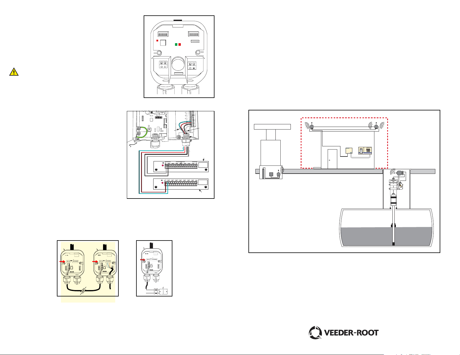
1. Connect Mag-Probe/Mag-Sump-sensor wires to the left connector and battery connections to the right connector.
2. Verify that green LED (Fig.12) flashes every 6 seconds followed by the adjacent red LED.
3. Make sure the LED closest to J3 connector in RCVR also
flashes with an interval of 6 seconds or smaller. Make sure
both the RS485 Transmit & Receive LEDs flash.
4. Close the lid.
Make sure the rubber gasket (O-ring) is properly placed
on the inner lining of lid and on screws that secure lid.
Overtightening lid screws may result in plastic damage
resulting in water infiltration.
5. Similarly install all other transmitters.
Fig. 12
PROBE
Manual No: 577013-877• Revision: A
S2S1
PWR
GND
J3
+IN -IN
BATTERY
S3
J4
TLS RF Wireless System
Quick Startup Guide
F. Connect TLS to TLS-RF
1. In this example, device output 1 (Item 1 Fig. 13) is
a Mag probe - Observe polarity.
2. In this example, device output 2 (Item 2) is a Mag
G
15V
C
D
B
E
A
REPEATER
F
9
0
8
1
7
2
6
3
5
4
PROBE 5
PROBE 4
RS-485
PROBE 3
+
PROBE 2
G
15V
PROBE 1
2
Sump Sensor - Observe polarity.
3. 0.5 inch (12.7mm) i.p.s. conduit (Item 3) to TLS
console.
3
4. Probe interface module (Item 4) in TLS console.
5. Smart Sensor interface module (Item 5) in TLS console.
Fig. 13
PROBE /
12341234
+ + + +
THERMISTOR
PROBE / THERMISTOR INTERFACE MODULE
1 2 3 4 5 6 7 8
S
MART
+ + + + + + + +
SENSOR
SMART SENSOR INTERFACE MODULE
PROBETHERMISTO
R
MAXIMUM PROB
OUTPUT
OUTPUT
G. Repeater Installation
Install repeater with clear line of sight to maximum number of transmitters as possible. You can give
power to repeater (Item 1 Figs. 14/15) either:
• From Receiver (Item 2 Fig. 14), or
• From a 15V/100mA power adapter (Item 2 Fig. 15)
PWR
TRANSMIT
RECEIVE
PWR
PWR
TRANSMIT
RECEIVE
+15V
+
J4
J3
GND
+15v
GND
RS-485
REPEATER
S2
S3
TRANSMIT
RECEIVE
+15V
+
J4
J3
GND
GND
+15v
RS-485
REPEATER
S2
S1
S1
S3
+15V
+
J4
J3
GND
+15v
GND
RS-485
REPEATER
S2
S1
S3
1
MAXIMUM
ALARM
WARNING
POWER
TLS-300
4
E
RATINGS
:
13 V
DC
0.2 AMP
RATINGS
DC
13 V
0.2 AMP
Monitoring System
5
Gnd
ACDC
+15 Vdc
Fig. 14
Fig. 15
H. Installation Verification
Select the Diagnostic Mode in the TLS Console and go to In-Tank Diagnostic Function. Verify that all
Mag probe/Mag Sump Sensor serial numbers correctly match their installed locations.
Page 2
A. Install TLS-RF:
S
+15V
P
2
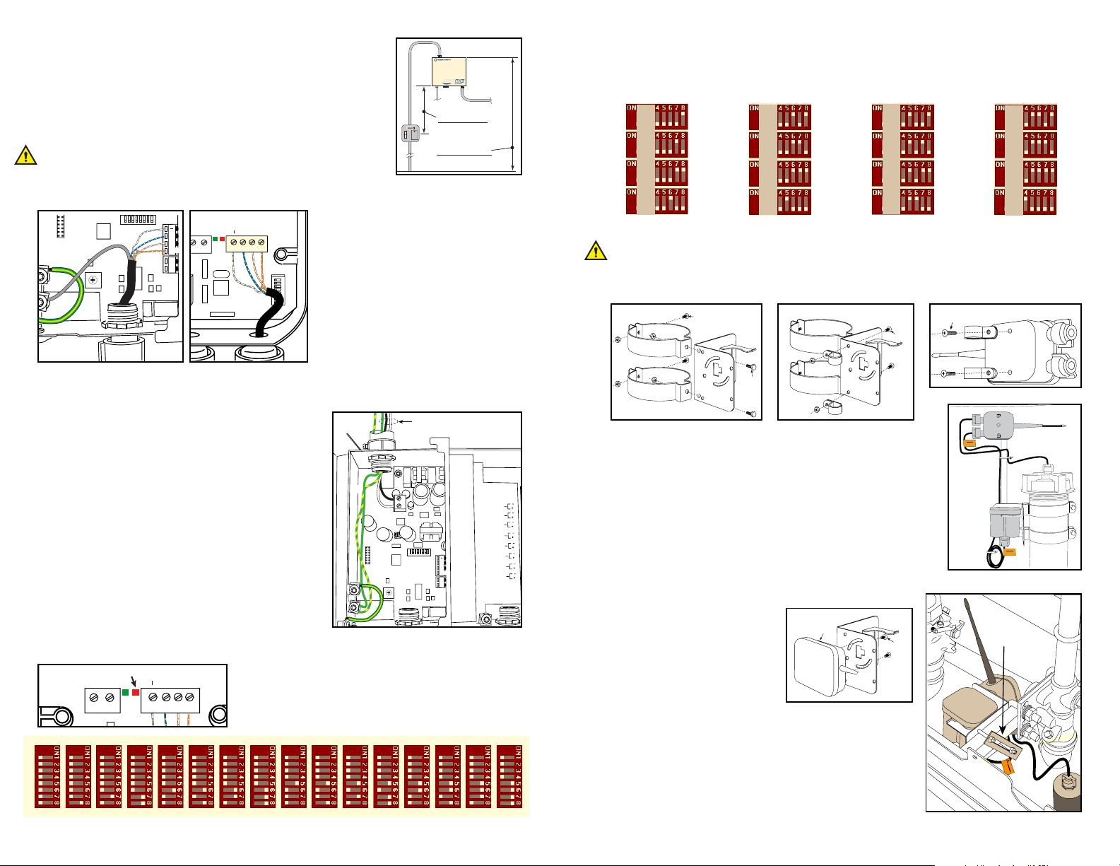
1. Mount TLS-RF unit indoors on 4 holes separated vertically by 5.7 inches/
145 mm and horizontally by 6.7 inches/170mm and using screws up to
0.187 inch/4.7mm diameter (dimensions shown in Fig. 1 are maximums).
2. Install 0.5 inch/12.7mm metal conduit on upper knockout on TLS-RF and
15A circuit breaker in power panel, or a 5A switched fuse spur with neon
indication.
3. Turn off all the 8 DIP switches inside TLS-RF.
4. Make arrow in rotary switch point to “1”.
B. Install RCVR
TLS-RF
Fig. 2
Receiver
RS-485
+
G
15V
G
15V
6
5
7
4
8
3
9
2
A
1
B
0
C
F
D
E
REPEATER
2
Fig. 3
GND
+
J3
GND
+15v
RS-485
S3
1. In TLS-RF connect 1 end of the RS-485
2. Connect the shield of the RS-485 cable to
S1
3. Run the RS-485 cable to Receiver, maxi-
4. In Receiver, turn off all 16 DIP switches
5. Connect 2nd end of RS-485 cable to RS-
C. Connect Power to TLS-RF, check PWR LED inside RCVR
1. From an independent 24 hour power supply at the distribution panel, run three 2.5 mm2 (minimum) standard color
coded wires (item 1 in Fig. 4); two for ac power and one
for earth to the fused spur.
2. Run one #12AWG (4 mm2) barrier ground wire (color
coded green/ yellow) from the earth bus bar at the distribution panel direct to the console location. Leave at least
1 meter of free cable for connection to the console.
3. Turn on power.
4. Near the left-lower corner inside TLS-RF, verify that
POWER LED is on and RX-485 TX LED is flashing at a
fast rate (10 times a second).
5. Near the top-central part inside Receiver, verify that PWR
LED is ON and RECEIVE LED is also flashing at the
same rate. Else check RS-485 wire connection.
D. Set Station ID Inside Receiver
Receiver
Fig. 5
+15V
J4
GND
+
J3
GND
+15v
Watch red LED, D8, between the 2 connectors, J4 & J3, for
more than 2 minutes, it should not flash (even once). If it does,
meaning it is receiving packets from nearby station, change to
another station ID on S2 DIP switches (see example settings
REPEATER
RS-485
below). Note down Station ID for use in transmitter set-up.
1000mm
39 inches
1500mm
59 inches
Fig. 1
cable (Belden #3107A or equiv.) to RS-485
connectors - one twisted pair connects to
terminals (- & +) and the second twisted
pair connects to terminals (+15 & G).
the ground lug.
mum length 250 feet/76 m.
marked as S1 & S2.
485 connectors as shown.
1
PROBE 8
PROBE 7
PROBE 6
PROBE 5
PROBE 4
PROBE 3
PROBE 2
PROBE 1
Fig. 4
INPUT
AC
RS-485
+
G
15V
G
15V
C
D
B
E
A
9
8
7
6
5
REPEATER
F
0
1
2
3
4
E. Install XMTR
1. Set the station ID, same as in receiver, on S2 DIP switches inside transmitter. Make sure switches 1
through 4 are turned off unless you want to use non-standard mode (refer site-prep manual).
2. Set unique Device ID for every transmitter on S1 DIP switches (4-8) inside transmitter (see below):
S1
1
2
3
4
Do not reset Dip Switches 1 - 3
5
6
7
8
Do not reset Dip Switches 1 - 3
9
10
11
12
Do not reset Dip Switches 1 - 3
13
14
15
16
Do not reset Dip Switches 1 - 3
3. Mount transmitter & battery pack.
Antenna is a sensitive part, please don’t try to rotate, unscrew or bend it and handle carefully. For
best communication quality, transmitter antenna should be horizontal and point in the direction of
receiver.
(i). Installing Transmitter on Mag Probe Riser
1
1
1
Fig. 6
1. Bolt appropriate size hangers to Battery pack support bracket as
shown using 1/4 x 20 x 0.5” (13 mm) hex head bolt/nuts (Item 1
Fig 6) - 2 places.
2. Loosely attach conduit hanger tightening bolts using 1/4 x 20 x 1.25
inch (32 mm) hex head bolt/nuts (Item 2 Fig. 6) – 1 each hanger.
3. Attach 2 small clamps to bracket as shown using two #10 x 0.5 inch
(M5x0.8 x 12.7) screws and nuts (Item 1 Fig. 7).
4. Attach 2 small clamps to back of transmitter as shown using #10 x
0.5 inch (M5x0.8 x 12.7) taptite screw (Item 1 Fig. 8) - 2 places.
(Go to iii).
(ii). Installing Transmitter in Dispenser Sump
1. Transmitter (Item 1 Fig. 10) attaches to battery support
bracket using 2-#10 x 0.5 inch
(M5x0.8 x 12.7) taptite screws
(Item 2 Fig. 10).
2. Get 1x 6 inch (25 x 152mm)
slotted flat bar and two 0.25 x
3 inch (13 x 76mm) bolts (Item
1 Fig. 11) from kit and clamp
battery support bracket to
square tubing support.
(Go to iii).
Fig. 7
1
Fig. 10
Fig. 8
Caution:
Battery
Connection
Caution:
Battery
Connection
Fig. 9
2
1
Caution:
Connection
Bat
ter
y
ID:0 1 2 3 4 5 6 7 8 9 10 11 12 13 14 15
Fig. 11
 Loading...