

Page 1

Site Prep Manual
TLS-IB
Form Number 8466X0-180 Series (RS-232 w/IFSF)
Form Number 8466X0-380 Series (RS-232 w/o IFSF)
Form Number 8466X0-580 Series (RS-232/RS-485)
Manual No: 577013-719 ● Revision: K
Page 2

Notice
Veeder-Root makes no warranty of any kind with regard to this publication, including, but not limited to, the implied warranties of
merchantability and fitness for a particular purpose.
Veeder-Root shall not be liable for errors contained herein or for incidental or consequential damages in
connection with the furnishing, performance, or use of this publication.
Veeder-Root reserves the right to change system options or features, or the information contained in this publication.
This publication contains proprietary information which is protected by copyright. All rights reserved. No part of this publication
may be photocopied, reproduced, or translated to another language without the prior written consent of Veeder-Root.
Contact TLS Systems Technical Support for additional troubleshooting information at 800-323-1799.
DAMAGE CLAIMS / LOST EQUIPMENT
Thoroughly examine all components and units as soon as they are received. If any cartons are damaged or missing, write a
complete and detailed description of the damage or shortage on the face of the freight bill. The carrier's agent must verify the
inspection and sign the description. Refuse only the damaged product, not the entire shipment.
Veeder-Root must be notified of any damages and/or shortages within 30 days of receipt of the shipment, as stated in our Terms
and Conditions.
VEEDER-ROOT’S PREFERRED CARRIER
1. Contact Veeder-Root Customer Service at 800-873-3313 with the specific part numbers and quantities that were missing
or received damaged.
2. Fax signed Bill of Lading (BOL) to Veeder-Root Customer Service at 800-234-5350.
3. Veeder-Root will file the claim with the carrier and replace the damaged/missing product at no charge to the customer.
Customer Service will work with production facility to have the replacement product shipped as soon as possible.
CUSTOMER’S PREFERRED CARRIER
1. It is the customer’s responsibility to file a claim with their carrier.
2. Customer may submit a replacement purchase order. Customer is responsible for all charges and freight associated with
replacement order. Customer Service will work with production facility to have the replacement product shipped as soon as
possible.
3. If “lost” equipment is delivered at a later date and is not needed, Veeder-Root will allow a Return to Stock without a restocking
fee.
4. Veeder-Root will NOT be responsible for any compensation when a customer chooses their own carrier.
RETURN SHIPPING
For the parts return procedure, please follow the appropriate instructions in the "General Returned Goods Policy” pages in the
"Policies and Literature" section of the Veeder-Root North American Environmental Products price list. Veeder-Root will not
accept any return product without a Return Goods Authorization (RGA) number clearly printed on the outside of the package.
©Veeder-Root 2018. All rights reserved.
Page 3

1 Introduction
Related Manuals ............................................................................................................1-1
Contractor Certification Requirements ...........................................................................1-1
Safety Symbols ..............................................................................................................1-2
Control Drawing .............................................................................................................1-3
2 Site Prep - International Installations
General ..........................................................................................................................2-1
Installation Levels ..................................................................................................2-1
In–Tank Probes .....................................................................................................2-2
Health and Safety ..........................................................................................................2-3
General..................................................................................................................2-3
Danger Areas ........................................................................................................2-3
Intrinsic Safety.......................................................................................................2-3
TLS-IB Location .............................................................................................................2-4
Mounting the TLS-IB ......................................................................................................2-6
Cable Specifications ......................................................................................................2-7
Field Wiring ....................................................................................................................2-7
Probe to TLS-IB Location (Level 1 Installations Only)...........................................2-7
Maximum Cable Lengths.......................................................................................2-7
Ducting Entry to TLS-IB Location ..........................................................................2-7
Equipment Connected To The RS-232 Port ..................................................................2-7
Table of Contents
3 Site Prep - U.S and Canadian Installations
National Electrical Code Compliance .............................................................................3-1
Probe-to-Console Wiring .......................................................................................3-1
Power Wiring .........................................................................................................3-1
In–Tank Probes .....................................................................................................3-2
Probe Junction Boxes............................................................................................3-2
Probe Wiring Safety Issues ...........................................................................................3-2
Mounting the TLS-IB ......................................................................................................3-3
4 Wiring/Miscellaneous For TLS-IB Consoles W/RS-232 & With & W/O
IFSF)
Probe Wiring Precautions ..............................................................................................4-1
Probe Wiring Positions and Labeling.....................................................................4-1
Connecting Probes to the TLS-IB ..................................................................................4-2
Auto Probe Configuration ......................................................................................4-2
Manual Probe Configuration..................................................................................4-2
Connecting IFSF Wiring to TLS-IB .................................................................................4-3
Connecting Serial Communication Wiring to the TLS-IB ...............................................4-5
Connecting Power Wiring to TLS-IB ..............................................................................4-6
Troubleshooting .............................................................................................................4-8
Replacing the CPU Board .....................................................................................4-8
PROM Chip Replacement (Software Upgrade).....................................................4-9
Replacing the Power Supply Board.....................................................................4-12
Neuron Service Switch ........................................................................................4-13
TLS-IB Specifications ..................................................................................................4-13
Physical Specifications ........................................................................................4-13
Environmental Specifications ..............................................................................4-14
Electrical Specifications.......................................................................................4-14
Software Specifications .......................................................................................4-14
IFSF Interface......................................................................................................4-14
iii
Page 4

Table of Contents
Optional RS-232 Serial Interface.........................................................................4-14
Signal Input Specifications ..................................................................................4-15
TLS-IB IFSF Commands .....................................................................................4-16
5 Wiring/Miscellaneous For TLS-IB Consoles W/RS-232 & RS-485
Probe Wiring Precautions ..............................................................................................5-1
Probe Wiring Positions and Labeling.....................................................................5-1
Connecting Probes to the TLS-IB ..................................................................................5-1
Auto Probe Configuration ......................................................................................5-2
Manual Probe Configuration..................................................................................5-2
Connecting Serial Communication Wiring to the TLS-IB ...............................................5-3
J11/J12 Jumper Positions (Table 5-1)...................................................................5-3
Connecting Power Wiring to TLS-IB ..............................................................................5-4
Troubleshooting .............................................................................................................5-6
Replacing the CPU/Power Supply Board ..............................................................5-6
Software Upgrade..................................................................................................5-6
TLS-IB Specifications ....................................................................................................5-8
Physical Specifications ..........................................................................................5-8
Environmental Specifications ................................................................................5-8
Electrical Specifications.........................................................................................5-8
Software Specifications .........................................................................................5-8
Serial Communications Interface (SCI) .................................................................5-8
Wiring Connections ...............................................................................................5-9
Serial Interface Commands...................................................................................5-9
Response Message Format For Function Code 64C ..........................................5-11
Figures
Tables
Figure 1-1. Control Drawing Showing An Example TLS-IB System Site Layout .......1-3
Figure 2-1. Determining The Minimum Mag Probe Length ....................................2-2
Figure 2-2. Typical TLS-IB Installation ...................................................................2-5
Figure 2-3. TLS-IB Dimensions And Designated Conduit Knockouts ....................2-6
Figure 4-1. Connecting Mag Probe Wiring To TLS-IB ...........................................4-3
Figure 4-2. Connecting IFSF Network Wiring To TLS-IB .......................................4-4
Figure 4-3. Connecting Serial Communication Wiring To TLS-IB ..........................4-5
Figure 4-4. Wiring AC Power To The TLS-IB .........................................................4-7
Figure 4-5. TLS-IB CPU Board ..............................................................................4-8
Figure 4-6. Clearing RAM ....................................................................................4-10
Figure 4-7. Removing PROM Chip ......................................................................4-11
Figure 4-8. Replacing PROM Chip .......................................................................4-12
Figure 4-9. Manually Transmitting Neuron ID ......................................................4-13
Figure 5-1. Connecting Mag Probe wiring to TLS-IB .............................................5-2
Figure 5-2. Connecting Serial Communication Wiring To TLS-IB ..........................5-3
Figure 5-3. Wiring AC Power To The TLS-IB .........................................................5-5
Figure 5-4. TLS-IB Firmware Update Screen .........................................................5-7
Table 1-1.
Table 2-1.
Table 2-2.
Applicable Manual Sections By Console Form Nu
Probe Cable Specification (GVR P/N 222–001–0029)
Maximum Of 305 Metres Per Probe .......................................................2-7
Data Transmission Cable Specifica
tion (GVR P/N 4034-0147) .............2-7
mber ........................1-1
-
iv
Page 5

Table of Contents
Table 4-1. TLS-IB IFSF Node Address Selections ..................................................4-4
Table 4-2. TLS-IB Serial Interface Connections ....................................................4-15
Table 4-3. TLS-IB Serial Commands .....................................................................4-15
Table 4-4. Tank Level Gauge Database ................................................................4-16
Table 4-5. Tank Level Gauge Error Code Database .............................................4-16
Table 4-6. Tank Probe Database ..........................................................................4-16
Table 4-7. Tank Temperature Table Database .....................................................4-17
Table 4-8. Tank Probe Error Code Database ........................................................4-17
Table 5-1. J11/J12 Jumper Positions ......................................................................5-3
Table 5-2. SCI Wiring Connections .........................................................................5-9
Table 5-3. TLS-IB Serial Commands .......................................................................5-9
v
Page 6
1 Introduction
This manual describes site preparation, installation, wiring and set up for TLS-IB consoles. Consult Table 1-1
below to determine the sections of this manual that will apply to your TLS-IB console.
Table 1-1. Applicable Manual Sections By Console Form Number
Section TLS-IB Console Form Number
1
All2
3
Applies To:
4
846620-180, 846660-180, 846690-180 (RS-232 with IFSF)
846620-380, 846660-380, 846690-380 (RS-232 w/o IFSF)
5 Applies To:
846620-580, 846660-580, 846690-580 (RS-232/RS-485)
Related Manuals
577013-578 TLS Monitoring Systems Contractors’ Site Preparation Guide
576013-858 Direct Burial Cable Installation Instructions
577014-031 TLS Magnetostrictive Probes International Installation Instructions
577013-744 Mag Plus Probe Installation Guide
576013-635 Veeder-Root RS-232 Serial Interface Manual
Contractor Certification Requirements
Veeder-Root requires the following minimum training certifications for contractors who will install and setup the
equipment discussed in this manual:
Installer Certification (Level 1): Contractors holding valid Installer Certification are approved to perform wiring
and conduit routing; equipment mounting; probe, sensor and carbon canister vapor polisher installation; wireless
equipment installation; tank and line preparation; and line leak detector installation.
Technician Certification (Level 2/3): Contractors holding valid Technician Certifications are approved to
perform installation checkout, startup, programming and operations training, system tests, troubleshooting and
servicing for all Veeder-Root Series Tank Monitoring Systems, including Line Leak Detection. In addition,
Contractors with the following sub-certification designations are approved to perform installation checkout, startup,
programming, system tests, troubleshooting, service techniques and operations training on the designated system.
•Wireless 2
• Tall Tank
Warranty Registrations may only be submitted by selected Distributors.
1-1
Page 7
Introduction Safety Symbols
OFF
Safety Symbols
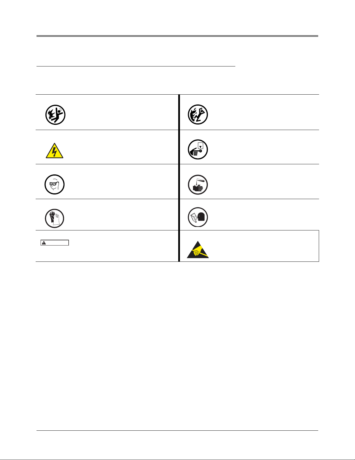
The following safety symbols may be used throughout this manual to alert you to important safety hazards and
precautions.
WARNING
EXPLOSIVE
Fuels and their vapors are extremely explosive if
ignited.
ELECTRICITY
High voltage exists in, and is supplied to, the
device. A potential shock hazard exists.
WEAR EYE PROTECTION
Fuel spray from residual pressure in the lines can
cause serious eye injuries. Always wear eye protection.
GLOVES
Wear gloves to protect hands from irritation or
injury.
WARNING
Indicates a hazardous situation which, if not
avoided, could result in death or serious injury.
FLAMMABLE
Fuels and their vapors are extremely flammable.
TURN POWER OFF
Live power to a device creates a potential shock
hazard. Turn Off power to the device and associated accessories when servicing the unit.
INJURY
Careless or improper handling of materials can
result in bodily injury.
READ ALL RELATED MANUALS
Knowledge of all related procedures before you
begin work is important. Read and understand
all manuals thoroughly. If you do not understand
a procedure, ask someone who does.
STATIC SENSITIVE COMPONENTS
Wear grounded anti-static wrist strap before
handling a TLS-IB CPU board.
1-2
Page 8
Introduction Control Drawing
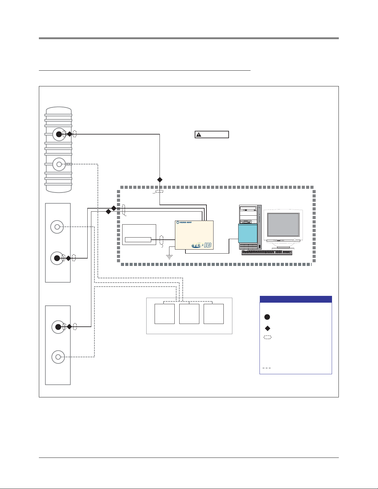
MP
MP
Non-Hazardous Area
120 OR 240 VAC
MP
Magnetostrictive Probe
Hazardous
Area
DISPENSERS
Forecourt
Epoxy Sealed Connection in
a Weatherproof Junction Box
Seal-Off
LEGEND
Rigid Conduit (Ducting)
IS
IS
PA
Conduit Enters Console in an
Intrinsically Safe Area Knockout
Conduit Enters Console in a
Power Area Knockout
IS
PA
Product piping
Double Wall Tank
Single Wall Tank
Single Wall Tank
MP
DP
Intrinsically safe wiring shall be installed in accordance with Article
504-20 of the latest National Electrical Code (NFPA 70).
Note: Conduit (ducting) requirements are dependent on local electrical
regulations. For probe-to-console wiring, shielded cable is required
regardless of conduit requirements.
Circuitry within the TLS-IB Console barrier forms an intrinsically safe,
energy-limited sys
tem. This system makes TLS-IB probes safe for use
in a Class I, Group D hazardous location. TLS-IB probe wiring is
intrinsically safe only when connected to Veeder-Root's TLS-IB
Consoles. Reference Form Number 8466 TLS-IB Console and Form
Numbers 8462, 8463, 8473, and 8493 (Probes).
Circuit breaker panel
or Fused, switched,
neon indication spur
WAR NIN G
Substitution of components may
impair intrinsic safety.
Control Drawing
Figure 1-1. Control Drawing Showing An Example TLS-IB System Site Layout
1-3
Page 9

2 Site Prep - International Installations
NOTICE
General
This document describes the procedures necessary to prepare the site, ready for the installation of the Veeder–
Root TLS Series Underground Storage Tank Monitoring Systems.
This manual does not cover the site preparation necessary for the installation of Veeder–Root Delivery Information
Systems (DIS). For information on these products please refer to the relevant manuals.
Veeder–Root maintains a continuous process of product development and therefore product specifications may
not be as described in this manual. Please contact the Veeder-Root office nearest you, or visit our website at
www.veeder.com for information on new or updated products. Changes affecting products or procedures
described in this manual will be reported in subsequent revisions. Veeder–Root has taken every care in the
compilation of this manual; however it is the installers' responsibility to take every precaution to safeguard
themselves and others.
Every person working with Veeder–Root equipment is expected to take every safety precaution possible and to
have read this manual, particularly the sections referring to health and safety.
Deviation from the specifications contained in this manual can result in rework, delays in
system installation and additional installation charges.
Contractors are advised to contact their nearest Veeder–Root office where local conditions may preclude using
the specifications contained in this manual.
INSTALLATION LEVELS
Veeder–Root require that certain facilities are installed by contractors, nominated by the customer, prior to
Veeder–Root attending the site for the installation of a TLS-IB system. These facilities vary dependent on the
installation contract agreed between Veeder–Root and the customer. Two levels of site preparation exist and are
described below:
Level 1 Installation
The customer or his elected contractor will supply (unless stated otherwise) and install the following:
• Console power supply and earth.
• External devices power supply and cabling.
• Peripheral devices cabling.
• Probe cable ducting
• Probe field cables
• Probe risers
• The contractor will seal all ducting after system testing has been carried out.
Level 2 Installation
The contractor will install the following:
• TLS-IB power supply and earth.
• External devices power supply and cabling.
2-1
Page 10
Site Prep - International Installations General
NOTICE
Top of probe
manway
Top of 2”, 3” or 4”
(50, 76 or 102mm)
tank opening
Minimum
Probe length
STP manway
3" (76mm) min. clearance from
top of canister to top of riser (Typ.)
Probe canister must be
within riser pipe (Typ.)
Manway cover
10" (254mm) minimum
riser length (Typ.)
Recommended distance
between probe and STP
is at least 12” (305mm)
OR
OR
Recommended distance
between probe and
delivery riser is at least 24” (610mm)
Install drop tube discharge
oriented away from probe
• Probe cable ducting.
• The contractor will seal all ducting after system testing has been carried out.
Unless stated otherwise, instructions in this manual refer to both levels of site preparation.
IN–TANK PROBES
Magnetostrictive Probes are capable of performing precision tank testing, as described by the United States
Environmental Protection Agency, at [0.38 litres per hour (0.1 gph) and 0.76 litres per hour (0.2 gph)] when
combined with the in-tank leak testing features of a TLS Console.
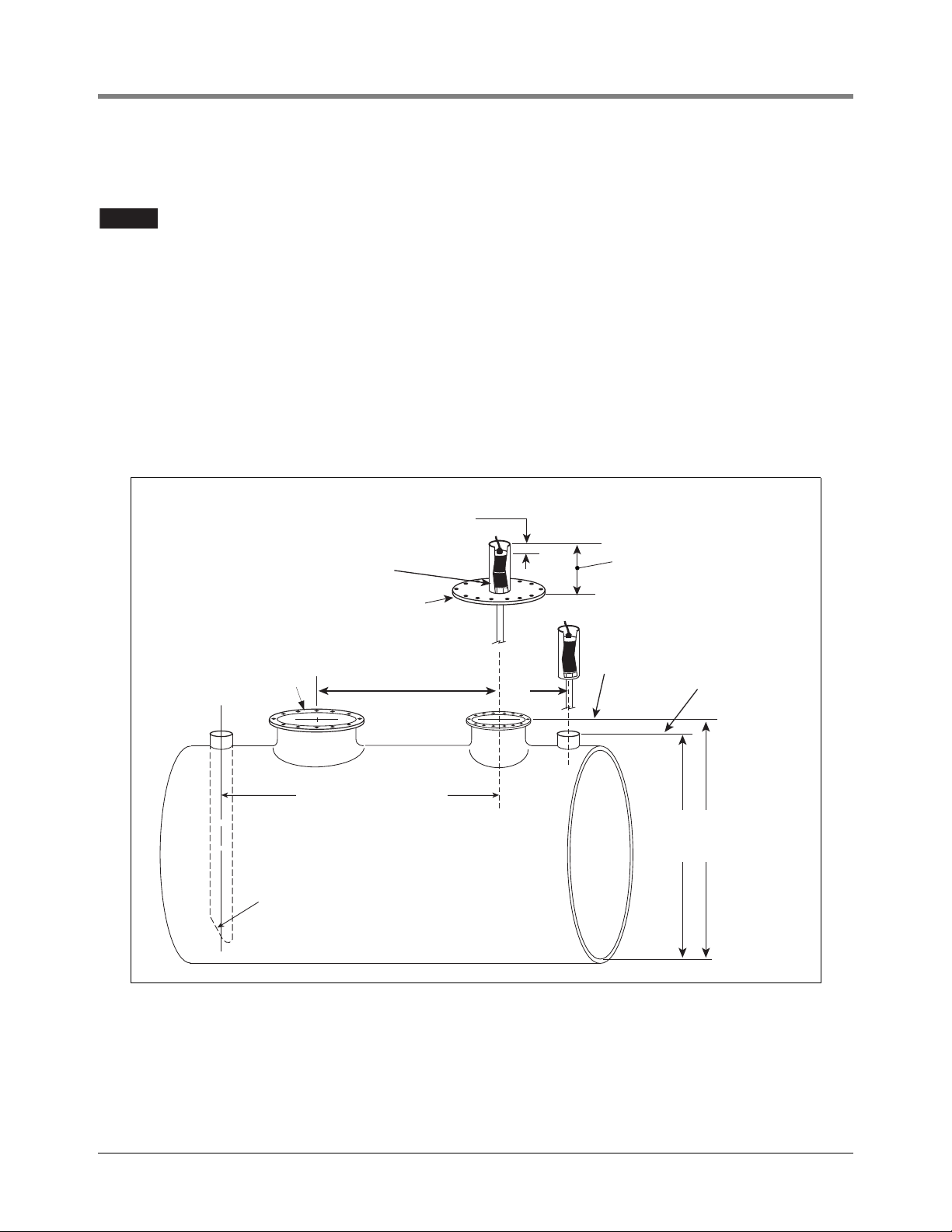
Determining Mag Probe Length For Installation In A Dedicated Riser
1. Measure the distance from the bottom of the tank to the top of the probe manway, or the 2-, 3- or 4-inch (50,
76, or 102mm) tank opening - this is the minimum probe length (ref. Figure 2-1).
2. The probe canister must be within the riser pipe (minimum length of 10 inches [254mm]).
Figure 2-1. Determining The Minimum Mag Probe Length
For further information on the performance, specification and selection of in-tank probes, please contact your local
Veeder-Root representative.
2-2
Page 11
Site Prep - International Installations Health and Safety
WARNING
NOTICE
Health and Safety
GENERAL
Ensure that all local council, U.K. and E.C. laws and regulations are complied with. Also ensure that all recognised
safety codes are followed.
Every person working with Veeder–Root equipment is expected to take every safety
precaution possible in the installation of the TLS-IB and probes.
Contractors must ensure that supervisory personnel on the installation site are aware of their presence and
requirements, especially the provision of safe working areas and isolation from AC electrical power.
Leaking underground tanks can create serious environmental and health hazards. It is the contractor's
responsibility to comply with the instructions and warnings found in this manual.
Reference manual number 577013-578 for additional product safety information.
DANGER AREAS
WARNING
TLS System products will be operated near the highly combustible
environment of a fuel storage tank.
FAILURE TO COMPLY WITH THE FOLLOWING WARNINGS AND SAFETY
PRECAUTIONS COULD CAUSE DAMAGE TO PROPERTY, ENVIRONMENT,
RESULTING IN SERIOUS INJURY OR DEATH.
If the underground storage tank to be fitted with a TLS system either contains or at any time has contained
petroleum products then the tank inspection chamber must be considered a hazardous environment as defined in
IEC EN 60079-10 Classification of Hazardous Areas. Suitable working practices for this environment must be
observed.
INTRINSIC SAFETY
The design of Veeder-Root products limits the power in the wiring to the in-tank probes and keeps this wiring
physically separated from any other. It is the responsibility of the contractor to maintain the effectiveness of these
safety features by preparing the installation site in accordance with the instructions and warnings which follow.
Failure to do so could create danger to life and property.
Circuitry within the probe and console barrier forms an intrinsically safe, energy limited system. This system makes
the probes suitable for use in hazardous locations. Probe wiring is intrinsically safe only when connected to the
TLS-IB unit.
Substitution of specified components may impair intrinsic safety.
All probe wiring must be contained in dedicated ducts.
2-3
Page 12
Site Prep - International Installations TLS-IB Location
NOTICE
WARNING
An explosion could occur if other wires share ducts with intrinsically safe
probe wiring. Ducting from probes must not contain any other wiring circuits.
FAILURE TO COMPLY WITH THIS WARNING COULD RESULT IN EXPLOSION,
DEATH, SERIOUS PERSONAL INJURY, PROPERTY LOSS OR EQUIPMENT
DAMAGE.
TLS-IB Location
The TLS-IB should be located on an inside wall of the forecourt building Be sure the console will be protected
from vibration, extremes in temperature and humidity, rain and other conditions that could cause equipment
malfunction.
The equipment is designed to operate safely under the following range of conditions:
• Altitude up to 2000 m.
• Temperature range of 0 to 40°C.
• A maximum relative humidity of 95% RH (non-condensing) at temperatures up to 40°C.
• Main supply voltage fluctuations not exceeding +/- 10%
• Pollution Degree Category 2 Installation Category II
The TLS-IB unit must be installed within the interior of buildings.This unit is not suitable for
any external location.
Ensure that the TLS-IB is located where neither it nor its associated cabling will be damaged by doors, furniture,
barrows, etc. Consider the ease of routing wiring, ducting and probe cables to the unit.
Overall dimensions and weight of the TLS-IB are: height - 163 mm, width - 188 mm, depth - 50 mm, weight - 1.8
kg.
To allow for maintenance ensure that the console is in an accessible area, even when the console doors are open.
If the unit requires cleaning, do not use any liquid materials (e.g. cleaning solvents). It is recommended that the unit
be wiped with a clean dry cloth when necessary.
Ensure that all relevant subcontractors and other personnel are aware of the selected location.
The TLS-IB is installed by Veeder–Root authorised engineers.
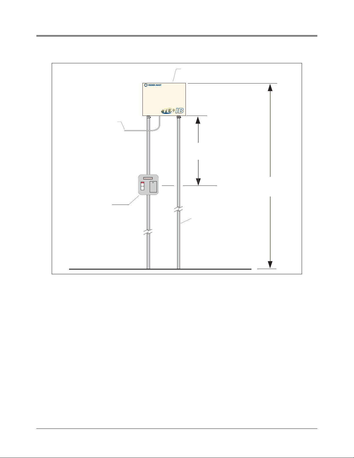
TLS-IB power must come from a dedicated circuit via a fused, switched, neon indication spur within 1 metre of the
console position. The spur must be clearly marked to identify it as the means for disconnecting the console. Input
power must be a 24-hour clean supply. A typical installation is shown in Figure 2-2.
2-4
Page 13
Site Prep - International Installations TLS-IB Location
tlsnt\tlsibmnt.eps
1000 mm
(Maximum)
1500 mm
(Maximum)
One 5 ampere fused,
switched, neon indication
spur (for 240 Vac), or a
dedicated circuit breaker
rated for 15 amperes, 120 Vac
or 240 Vac. NOTE, circuit breaker
must be marked as the power
disconnect for the TLS-IB Console.
IFSF cable
(Optional)
Conduit for probe
field cables
Alternative knockouts
for cable entries
Figure 2-2. Typical TLS-IB Installation
2-5
Page 14

Site Prep - International Installations Mounting the TLS-IB
0.34'' (8,6) typ.
0.34'' (8,6) typ.
7.4" (188)
6.4''
(163)
5.7''
(145)
2" (50)
5.3'' (135)
1.24''
(31)
5.3'' (135)
0.54" inside (M12 conduit),
1/2'' I.P.S. (International Pipe Size) outside (PG7 conduit)
knockouts 4 places - bottom (2), left side (1), and top (1)
1/2", 3/4'', & 1'' I.P.S.
conduit knockout pattern (2 places)
Cover (shown open
for reference)
tlsnt\ibdim.eps
0.22'' (5,6) dia.
mounting holes (4 places)
0.93'' (23)
0.93'' (23)
3''
(73)
0.7''
(17)
0.93''
(23)
6.7" (170)
NOTE: Numbers
in parenthesis are
in millimetres.
0.93''
(23)
Mounting the TLS-IB
Install the TLS-IB fastening devices to the mounting surface using the hole pattern 170 x 145mm (6.7 x 5.7 inches)
shown in Figure 2-3. Mounting screws up to 4.7mm (3/16-inch) diameter may be used.
Mount the TLS-IB to the mounting surface using the four mounting flanges on the back of the unit. Install ducting
or conduit between the TLS-IB and the power panel. Figure 2-3 shows the three designated knockouts (one each
on top, left side, and bottom) through which power wiring can safely enter the TLS-IB.
Figure 2-3. TLS-IB Dimensions And Designated Conduit Knockouts
2-6
Page 15
Site Prep - International Installations Cable Specifications
WARNING
Cable Specifications
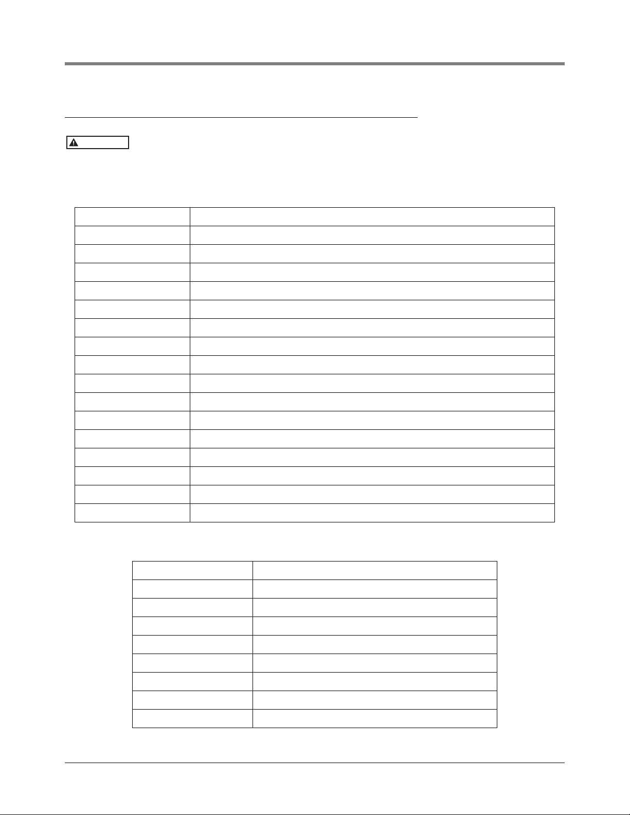
The cable type tables listed below form part of the individual system ATEX approval.
Substitution of cable may impair intrinsic safety and may invalidate system approval.
All specifications are in free air at +30°C:
Table 2-1. Probe Cable Specification (GVR P/N 222–001–0029) - Maximum Of 305 Metres Per Probe
Number of Cores 2
Conductors Bare copper, 24/0.20mm, diameter 1.1mm
Insulation PVC R2 to CEI 20-11, colour black 1/black 2, radial thickness 0.54mm, twisting 1x 2, lay pitch 76mm
Shielding Aluminium polyester tape, tinned copper drain wire 7/0.30mm
Sheath PVC RZ FR hydrocarbon resistant, colour blue, radial thickness 0.80mm
Diameter 6.10mm
Conductor Resistance 25 ohm/km
Drain Wire Resistance 15 ohm/km
Capacitance 0.14 F/km (140 pF/m)
Inductance 0.65 mH/km (0.65 H/m)
LR Ratio 17 H/ohm
Insulation Resistance 1050 Mohm/km
Voltage Core to Core 500
Voltage Core to Screen 500
Voltage Earth to Screen 500
Voltage Test 1kV/1 minute
Standard IEC 227-74
Table 2-2. Data Transmission Cable Specification (GVR P/N 4034-0147)
Cable Type 2 x twisted pair, PVC insulated, foil wrapped, common drain
Conductor Stranding 7/0.25mm
Characteristic Impedance 58 ohms
Capacitance 203 pF per metre
Attenuation 5.6 dB per 100 m
Operating Temp. Range –30°C to +70°C
Insulation PVC
Sheath Polyethylene
Sheath Colour Grey
2-7
Page 16

Site Prep - International Installations Field Wiring
WARNING
NOTICE
NOTICE
NOTICE
Table 2-2. Data Transmission Cable Specification (GVR P/N 4034-0147)
Cable Type 2 x twisted pair, PVC insulated, foil wrapped, common drain
Core Colours Black, red, green, white
Nominal Outside Diameter 4.2 mm
Recommended UK Supplier: RS Components Ltd., Stock number (500metre drum) 368–312
Field Wiring
PROBE TO TLS-IB LOCATION (LEVEL 1 INSTALLATIONS ONLY)
Pull one two core, Probeflex cable from the TLS-IB location to each probe location.
An explosion could occur if other, non–intrinsically safe wires share TLS intrinsically
safe wire conduits or wiring troughs. Conduits and wiring troughs from probes and
sensors to the console must not contain any other wires.
At least 2 metres of free cable must be left for connection at both the TLS-IB and the probe
locations.
Ensure that all cables are correctly identified. All probe field wiring
must be legibly and permanently labelled with
the tank number.
Failure to correctly mark probe field wiring may lead to rework, delays in system installation
and additional charges.
MAXIMUM CABLE LENGTHS
A maximum of 305 metres of cable length per sensor or probe must be observed.
DUCTING ENTRY TO TLS-IB LOCATION
Connection to the TLS-IB may only be made by a Veeder–Root authorised engineer.
The cable route from the ducting entry to the TLS-IB must be clearly defined and all necessary preliminary work
undertaken. All necessary holes must be drilled through walls, counters, etc.; cable trays fitted, ducting with draw
cords installed and adequate access for the installation of the cable provided.
Equipment Connected To The RS-232 Port
Any equipment such as a pump controller or point–of–sale terminal connected to the RS-232 port must meet the
following criteria:
• The equipment must have an EIA standard RS-232C or RS-232D communications protocol.
• The equipment must NOT be installed over or in a hazardous location.
The RS-232 Interface can be used for direct local attachment of terminals if the cable run is no more than 15
metres. Veeder-Root do not guarantee proper equipment operation if RS-232 cable runs exceed 15 metres.
RS-232 cable runs longer than 15 metres could result in data errors.
Run cable from the peripheral equipment location to the system console location. At least 1 metre of free cable
must be left for subsequent connection at both ends.
2-8
Page 17

3 Site Prep - U.S and Canadian Installations
NOTICE
National Electrical Code Compliance
The following information is for general reference and is not intended to replace recommended National Electric
Code (NEC) procedures. It is important for the installer to understand that electrical equipment and wiring located
in Class I, Division 1 and 2 installations shall comply with the latest appropriate Articles found in the National
Electric Code (NFPA 70) and the Automotive and Marine Service Station Code (NFPA 30A).
PROBE-TO-CONSOLE WIRING
Wire Type
To ensure the best operating systems available, Veeder-Root REQUIRES the use of shielded cable for all probes
regardless of conduit material or application. In these installations, shielded cable must be rated less than 100
picofarad per foot and be manufactured with a material suitable for the environment, such as Carol™ C2534 or
Belden™ 88760, 8760, or 8770.
Throughout this manual, when mentioning any cable or wire being used for probe-toconsole wiring, it will be referring to shielded cable.
Wire Length
Improper system operation could result in undetected potential environmental and health hazards if the probe-toconsole wire runs exceed 1000 feet. Wire runs must be less than 1000 feet to meet intrinsic safety requirements.
Splices
Veeder-Root recommends that no splices be made in the wire run between a probe junction box and the console.
Each splice degrades signal strength and could result in poor system performance.
Wire Gauges - Color coded
Shielded cable must be used in all installations. Wires should be #14-#18 AWG stranded copper wire and
installed as a Class 1 circuit. As a alternate method when approved by the local authority having jurisdiction, 22
AWG wire such as Belden 88761 may be suitable in installations with the following provisions:
• Wire run is less than 750 feet
• Capacitance does not exceed 100 pF/foot
• Inductance does not exceed 0.2 H/foot
• Total cable length per installation 22,000 feet.
POWER WIRING
Wires carrying 120 or 240 Vac from the power panel to the console should be #14 AWG (or larger) copper wire
for line, neutral and chassis ground (3); and #12 AWG copper wire for barrier ground.
3-1
Page 18

Site Prep - U.S and Canadian Installations Probe Wiring Safety Issues
IN–TANK PROBES
Magnetostrictive Probes are capable of performing precision tank testing, as described by the United States
Environmental Protection Agency, at 0.1 gph and 0.2 gph per hour when combined with the in-tank leak testing
features of a TLS Console. Reference Figure 2-1 on page 2-2 to determine the minimum Mag Probe length for
installation in a dedicated riser.
PROBE JUNCTION BOXES
Weatherproof electrical junction boxes with a gasketed cover are required on the end of each probe conduit run at
the manhole or monitoring well location. Gasketing or sealing compound must be used at each entry to the
junction box to ensure a waterproof junction. The interior volume of each junction box must be a minimum of 16
cubic inches.
Veeder-Root recommends the following junction boxes or equivalent:
• Appleton Electric Co. - JBDX junction box, JBK-B cover, and JB-GK-V gasket.
• Crouse-Hinds Co. - GRFX-139 junction box, GRF-10 cover, and GASK-643 gasket.
Probe Wiring Safety Issues
WARNING
Probes operate in areas where flammable liquids and explosive vapors may
be present.
FAILURE TO COMPLY WITH THIS WARNING COULD RESULT IN EXPLOSION,
DEATH, SERIOUS PERSONAL INJURY, PROPERTY LOSS OR EQUIPMENT
DAMAGE.
1. Read thoroughly and follow the instructions shipped with each probe.
2. Probe wiring conduit must not contain any other wires.
3. Probe wiring and conduits must enter the TLS-IB only through their
designated areas (see Figure 2-3 on page 2-6).
4. Power and communication wires and conduit must not enter the
intrinsically safe compartment of the TLS-IB.
Wiring between the TLS-IB and the probes is of limited electrical power so that there is insufficient energy to ignite
fuel. In the TLS-IB, the low power probe wiring is considered intrinsically safe because it is physically isolated from
all high power wiring. To maintain the integrity of this safety feature probe wiring can not share the same conduit
with power wiring. In addition, probe cables can only enter the TLS-IB through the designated intrinsically safe
area knockouts.
If the TLS-IB is being retrofitted into a paved site, you can cut grooves in the pavement, run direct burial cable to
the probes, and then seal over the cable grooves.
Before trenching, you should diagram all conduit runs between the TLS-IB’s intended location and its deployed
probes. Your site diagram will help you calculate conduit and wiring lengths, and necessary quantities of junction
boxes, sealing boxes, clamps, brackets, etc.
Throughout this planning process and in the actual installation, you must follow all latest National Electric Codes,
and applicable federal, state, and local codes as regards conduit type, depth below grade, sealing, grounding, wire
capacities, direct burial (if permitted), etc.
3-2
Page 19

Site Prep - U.S and Canadian Installations Mounting the TLS-IB
NOTICE
If the intrinsically safe wires enter the building in a wiring trough, only intrinsically safe
wires (from TLS-IB probes) can be in the trough. Keep all low power (intrinsically safe)
wiring physically isolated from high power wires in all wiring troughs per the NEC.
Mounting the TLS-IB
Install the TLS-IB fastening devices to the mounting surface using the hole pattern 170 x 145mm (6.7 x 5.7 inches)
shown in Figure 2-3 on page 2-6. Mounting screws up to 4.7mm (3/16-inch) diameter may be used.
Mount the TLS-IB to the mounting surface using the four mounting flanges on the back of the unit. Install ducting
or conduit between the TLS-IB and the power panel. Figure 2-3 shows the three designated knockouts (one each
on top, left side, and bottom) through which power wiring can safely enter the TLS-IB.
3-3
Page 20

4 Wiring/Miscellaneous For TLS-IB Consoles W/RS-232 &
NOTICE
OFF
NOTICE
With & W/O IFSF)
This section applies only to TLS-IB consoles with the following Form Numbers:
• 846620-180, 846660-180, 846690-180 (RS-232 with IFSF)
• 846620-380, 846660-380, 846690-380 (RS-232 w/o IFSF)
For Console Form Numbers 846620-580, 846660-580 and 846690-580 skip Section 4 and
proceed to Section 5.
WARNING
The equipment is used in location where lethal voltages and explosive vapors
or flammable fuels may be present.
FAILURE TO COMPLY WITH THE FOLLOWING WARNINGS AND SAFETY
PRECAUTIONS COULD CAUSE DAMAGE TO PROPERTY, ENVIRONMENT,
RESULTING IN SERIOUS INJURY OR DEATH.
For this system:
1. Comply with the latest National Electric Code, federal, state, and local
codes, and any other applicable safety codes. In addition, take necessary
precautions during installation, service, and repair to prevent personal
injury, property loss and equipment damage.
2. Refer servicing to trained and qualified personnel only.
3. Substitution of components may impair intrinsic safety.
4. Be sure AC power is “Off” before opening the TLS-IB cover and
connecting probe wires. Do not short any voltage across any barrier
terminal including probes.
Probe Wiring Precautions
To The Installer! You Must Read And Understand This Information. Reference manual number 577013-578 for
additional safety related information.
PROBE WIRING POSITIONS AND LABELING
In all cases, the devices wired to the TLS-IB input terminal blocks must be recorded to prevent improper
replacement during installation or service.
Wiring Assignments
Identify all probe wires according to their terminal block location using the self-adhesive numbering labels
furnished. Accurately record on the circuit directory label (top of I.S. compartment cover plate - see Figure 4-1),
the tank number of each probe as you attach wires to the probe input terminal block.
Once a device has been wired to certain terminals and the system has been programmed,
the wires from that device may not be relocated to other terminals without reprogramming
the system.
4-1
Page 21

Wiring/Miscellaneous For TLS-IB Consoles W/RS-232 & With & W/O IFSF) Connecting Probes to the TLS-IB
NOTICE
Connecting Probes to the TLS-IB
Connect the two color-coded/marked wires from each probe to the appropriate connectors (e.g., Probe 1) of the
Probe Terminal Block as shown in Figure 4-1.
Observe polarity when connecting probe wires!
Connect probe cable shields and drain wires to ground in the TLS-IB only, not at the field junction boxes. Do not
ground both ends of the shield.
AUTO PROBE CONFIGURATION
During a cold boot, the TLS-IB will automatically configure connected probes - CAUTION! For auto
configuration to occur, probes must be connected in sequence, starting at the Probe 1 input and
continuing with no skipped inputs.
For example, if you have 4 probes and you connect them to Probe inputs 1, 2, 3, and 4, auto configuration works
fine. But if you connect them to Probe 1, 3, 5, and 7 auto configuration doesn’t work, resulting in probe out alarms.
Also, the skipped inputs will be unusable.
MANUAL PROBE CONFIGURATION
If you connect probes after the system has been powered they must be manually configured. To configure probes
for the TLS-IB, use either the IFSF command Data ID 1, “Nb-Tanks” (see Table 4-4 on page 4-16); or the RS-232
“Set Tank Configuration”, serial command 601 (see Table 4-3 on page 4-15).
4-2
Page 22

Wiring/Miscellaneous For TLS-IB Consoles W/RS-232 & With & W/O IFSF) Connecting IFSF Wiring to TLS-IB
+
PROBE 6
+
PROBE 5
+
PROBE 4
+
PROBE 3
+
PROBE 2
+
PROBE 1
WARNING
SUBSTITUTION OF COMPONENTS
MAY IMPAIR INTRINSIC SAFETY.
NO REPAIRS SHOULD BE ATTEMPTED.
REFER SERVICING TO QUALIFIED
PERSONNEL ONLY.
AVERTISSEMENT
LA SUBSTITUTION DE COMPOSANTS
PEUT COMPROMETTRE LA SECURITE
INTRINSEQUE.
J5
SGL DBL
B
A
WIRING SIDE
G
J4
D1
LED1
IFSF
JP3
J8
U8
J7
L1
S1
SERVICE
RAM
IB
POWER
tlsnt\ibpbwr.eps
IFSF
CLR
N
M
L
C
L
R
R12-001
331470
R12-002
R12-003
R12-004
R12-005
R12-006
N
L
Attach probe cable shield and/or
drain wire to grounding lug
+
PROBE 8
+
PROBE 7
Probe Wiring
Black wire from probe
connects to terminal
White wire from probe
connects to + terminal
Circuit directory label
OFF
Figure 4-1. Connecting Mag Probe Wiring To TLS-IB
Connecting IFSF Wiring to TLS-IB
The TLS-IB’s circuit boards have lethal voltages present.
FAILURE TO COMPLY WITH THE FOLLOWING WARNINGS AND SAFETY
PRECAUTIONS COULD CAUSE DAMAGE TO PROPERTY, ENVIRONMENT,
RESULTING IN SERIOUS INJURY OR DEATH.
For this system:
1. Comply with the latest National Electric Code, federal, state, and local
codes, and any other applicable safety codes. In addition, take necessary
precautions during installation, service, and repair to prevent personal
injury, property loss and equipment damage.
2. Refer servicing to trained and qualified personnel only.
3. Substitution of components may impair intrinsic safety.
4. Be sure AC power is “Off” before opening the TLS-IB cover and
connecting wiring.
WARNING
4-3
Page 23

Wiring/Miscellaneous For TLS-IB Consoles W/RS-232 & With & W/O IFSF) Connecting IFSF Wiring to TLS-IB
OFF
+
PROBE 4
+
PROBE 3
+
PROBE 2
+
PROBE 1
AVERTISSEMENT
LA SUBSTITUTION DE COMPOSANTS
PEUT COMPROMETTRE LA SECURIT
INTRINSEQUE.
SGL DBL
B
A
WIRING SIDE
G
J4
D1
IFSF
JP3
J8
U8
J7
L1
S1
SERVICE
RAM
tlsnt\ibifwr.eps
IFSF
CLR
N
M
L
C
L
R
R12-001
331470
R12-002
R12-003
R12-004
R12-005
R12-006
IFSF Wiring
Connect two wires from IFSF
network to the two terminals
of J8 (no polarity).
LON Bus Termination
LON bus cable termination
jumper (JP3).
NOTICE
1. With AC power switched Off, connect the IFSF network wires to J8 in the TLS-IB as shown in Figure 4-2
below:
Figure 4-2. Connecting IFSF Network Wiring To TLS-IB
2. The LON cable termination jumper (JP3 in Figure 4-2) is shown in the single position (SGL). The single
position is used when the TLS-IB is a Free Topology Segment in the LON network and only one termination is
required. The double position (DGL) is used when the TLS-IB is a Doubly Terminated Bus Topology Segment
in the LON network and two terminations are required. To set the jumper in the DGL position, move it to the
right (jumper over the middle and right pins).
If the TLS-IB is not a terminating device on the IFSF network, you must remove the LON
cable termination jumper (JP3) from the board. Failure to do so will result in improper
operation.
3. Set the IFSF Node Address DIP switches on the CPU board (S1 in Figure 4-5 on page 4-8) to the desired
Node Address using the table below (U = switch open [up], D= set switch to closed position [down]). For
example, to enter a IFSF node address of 06, set switches 2 and 4 up, and switches 1 and 3 down.
Table 4-1. TLS-IB IFSF Node Address Selections
Dip Switch Setting
IFSF
Address
01 UU UU
02 DU UU
03 UD UU
04 DD UU
1234
05 UU DU
4-4
Page 24

Wiring/Miscellaneous For TLS-IB Consoles W/RS-232 & With & W/O IFSF) Connecting Serial Communication Wiring to the TLS-IB
OFF
+
PROBE 6
+
PROBE 5
+
PROBE 4
+
PROBE 3
+
PROBE 2
+
PROBE 1
REFER SERVICING TO QUALIFIED
PERSONNEL ONLY.
AVERTISSEMENT
LA SUBSTITUTION DE COMPOSANTS
PEUT COMPROMETTRE LA SECURITE
INTRINSEQUE.
J5
SGL DBL
B
A
WIRING SIDE
G
J4
D1
IFSF
JP3
J7
S1
SERVICE
RAM
tls
CLR
N
M
L
C
L
R
R12-001
331470
R12-002
L
+
PROBE 8
+
PROBE 7
Serial Comm Wiring
For RS-232 Network:
Connect TX to (B)
Connect RX to (A)
Connect Signal Ground to (G)
JP4
Table 4-1. TLS-IB IFSF Node Address Selections
Dip Switch Setting
IFSF
Address
1234
06 DU DU
07 UD DU
08 DD DU
09 UU UD
0A DUUD
0B UDUD
0C DDUD
0D UUDD
0E DUDD
0F UDDD
10 DD DD
Connecting Serial Communication Wiring to the TLS-IB
With AC power switched Off, connect the serial communication wiring to J7 in the TLS-IB as shown in Figure 4-3.
Figure 4-3. Connecting Serial Communication Wiring To TLS-IB
4-5
Page 25

Wiring/Miscellaneous For TLS-IB Consoles W/RS-232 & With & W/O IFSF) Connecting Power Wiring to TLS-IB
OFF
OFF
NOTICE
Connecting Power Wiring to TLS-IB
WARNING
The TLS-IB contains voltages which can be lethal. It is connected to devices
that must be intrinsically safe.
FAILURE TO COMPLY WITH THE FOLLOWING WARNINGS AND SAFETY
PRECAUTIONS COULD CAUSE DAMAGE TO PROPERTY, ENVIRONMENT,
RESULTING IN SERIOUS INJURY OR DEATH.
1. Turn power Off at the circuit breaker connecting the power supply wires.
2. Attach conduit from the power panel to the TLS-IB Power Area
knockouts only (1 on top and 2 on bottom, ref. Figure 2-3 on page 2-6).
1. Pull four wires between the power panel and the TLS-IB; three #14 AWG or larger diameter color-coded
wires for AC line (L), AC neutral (N) and chassis ground; and one #12 AWG (4 mm
2
cross-sectional area)
green and yellow wire for barrier ground.
For international applications, console power should come from a dedicated circuit via a fused, switched, neon
indication spur within one metre of the console position. From an independent 24 hour supply at the distribution panel, run three 2.5 mm
spur. Run three similar wires from the spur to the console location. Run one 4mm
2
(minimum) standard colour coded wires, live, neutral and earth, to the fused
2
wire, colour coded green/
yellow, from the earth bus bar at the distribution panel direct to the console location. Leave at least 1 metre of
free cable for connection to the console.
Use an ohmmeter to check the electrical resistance between the console’s metal case and
the earthing ground wire’s connection at the “known good earth ground” (copper rod driven
into ground, etc.). It should read less than 1 ohm.
2. Open the door of the TLS-IB and connect the four power/ground wires as shown in [Figure 4-4]. Do not
connect the power wires to breaker panel at this time.
4-6
Page 26

Wiring/Miscellaneous For TLS-IB Consoles W/RS-232 & With & W/O IFSF) Connecting Power Wiring to TLS-IB
+
PROBE 6
+
PROBE 5
+
PROBE 4
+
PROBE 3
+
PROBE 2
+
PROBE 1
WARNING
SUBSTITUTION OF COMPONENTS
MAY IMPAIR INTRINSIC SAFETY.
NO REPAIRS SHOULD BE ATTEMPTED.
REFER SERVICING TO QUALIFIED
PERSONNEL ONLY.
AVERTISSEMENT
LA SUBSTITUTION DE COMPOSANTS
PEUT COMPROMETTRE LA SECURITE
INTRINSEQUE.
+
PROBE 8
+
PROBE 7
J5
SGL DBL
B
A
WIRING SIDE
G
J4
D1
IFSF
JP3
J8
U8
J7
L1
S1
SERVICE
RAM
IB
POWER
esso\ibpowr.eps
Protective Earthing
Conductor (Green and
Yellow) Attach #12AWG
(4 mm
2
) barrier ground
wire to ground lug
Attach chassis ground
wire to ground lug
Power
Side
Intrinsically
Safe Side
IFSF
CLR
N
M
L
C
L
R
R12-001
331470
R12-002
R12-003
R12-004
R12-005
R12-006
N
L
Power Wiring
Connect neutral wire to upper
terminal of J5 (N). Connect
hot wire to lower terminal (L).
C26 C28
L2 L4
POWER WIRING NOTES:
1. Barrier ground must be #12 AWG (4 mm
2
cross-
sectional area) or larger diameter.
2. Check to be sure that the electrical resistance
between the console ground lug and a "known
good earth ground" is less than 1 ohm.
3. Connect the power supply wires in the power
panel to a separate dedicated circuit.
4. Electrical rating power input -- 120 Vac or
240 Vac, 50/60 Hz, 2 A maximum.
5. See the "Console Dimensions
and Designated
Conduit Knockouts" figure for actual locations of
power conduit knockouts into the console. Power
wiring must enter only in Power Area conduit
knockouts.
WARNING!
Shock hazard. Do not
touch metal ends of
capacitors C26/C28
or the metal bands
on chokes L2/L4.
Figure 4-4. Wiring AC Power To The TLS-IB
4-7
Page 27

Wiring/Miscellaneous For TLS-IB Consoles W/RS-232 & With & W/O IFSF) Troubleshooting
OFF
C23
+
Y2
U5
U29
NODE
ADDRESS
Y3
L1
5V
TLS-IB CPU BOARD
Cable to Power
Supply Board
tlsnt\ibcpu.eps
PROM chip (U29)
Serial Comm/IFSF
Node Address
Dip Switch (S1)
IFSF ROM
(U5)
S1
G 8V
These voltage test points are on the back of
the CPU board (directly behind this upper left
corner)
STATIC SENSITIVE COMPONENTS!
WEAR GROUNDED ANTI-STATIC WRIST
STRAP BEFORE HANDLING THIS BOARD!
1234
OPEN
Troubleshooting
This section contains information to help you diagnose system problems. Instructions are included for replacing
CPU and Power Supply boards in the event of a hardware failure and for installing a software upgrade. Also, the
location and use of the neuron service switch is discussed.
At the end of this section you will find a list of specifications for the TLS-IB.
REPLACING THE CPU BOARD
The CPU board must be replaced if the TLS-IB fails to communicate. Check the voltage between the GND and 5V
test points [Figure 4-5] on the back of the CPU board. This voltage should be between 4.75 - 5.25 Vdc; if not,
replace CPU board as follows.
1. Turn Off power to the system. Attach the anti-static strap to your wrist and to a good ground.
2. Disconnect the CPU cable from the Power Supply board. The CPU board snaps securely into place in the
door of the TLS-IB without the use of screws. There are two tabs on the top of the board that fit into two slots
in the top edge of the door. The bottom of the CPU board snaps in place between two pairs of detents
protruding from the bottom edge of the door. The CPU board is removed by inserting a straight-slot
screwdriver into one of the two indents on the bottom of the board and then gently prying against the door
until the board clears the upper detents, then rotating the board up slightly and toward you to clear the top
tabs from the slots in the door.
3. Replace the CPU board reversing the above steps.
Figure 4-5. TLS-IB CPU Board
4-8
Page 28

Wiring/Miscellaneous For TLS-IB Consoles W/RS-232 & With & W/O IFSF) Troubleshooting
OFF
PROM CHIP REPLACEMENT (SOFTWARE UPGRADE)
The PROM chip (U29) is replaced when a software upgrade is installed. This procedure requires that you perform
a RAM clear.
1. If possible, record the current setup information. Switch Off power to the system.
2. Open the front door of the TLS-IB. The CPU board is installed in the door.
3. Attach an anti-static strap to your wrist and to a good ground.
4. Move RAM clear jumper from NML to CLR position (Figure 4-6). Switch On power to TLS-IB and wait 30
seconds, then switch Off power to TLS-IB. Move the RAM clear jumper back to NML position.
5. Disconnect the ribbon cable connector from the CPU board. Remove the CPU board following the
instructions on the previous page.
6. Locate the PROM chip on the board (see Figure 4-5).
7. Remove the PROM chip following instructions in Figure 4-7.
8. Replace the PROM chip following instructions in Figure 4-8.
9. Replace the CPU board in the front door of the TLS-IB. Connect the CPU board cable to the Power Supply
board.
10. Switch On power to the TLS-IB and check your system configuration for proper setup.
4-9
Page 29

Wiring/Miscellaneous For TLS-IB Consoles W/RS-232 & With & W/O IFSF) Troubleshooting
J5
SGL DBL
B
A
WIRING SIDE
G
J4
D1
LED1
IFSF
JP3
J
U8
J7
S1
SERVICE
RAM
IB
POWER
IFSF
CLR
N
M
L
C
L
R
R12-001
331470
R12-002
R12-003
R12-004
R12-005
R12-006
N
L
Probe Status
Indicator (LED1)
IFSF Status
Indicator (D1)
RAM Clear Jumper (J4)
shown in Normal position.
You must move jumper to
middle and right pins to
clear RAM:
J4
N
M
L
C
L
R
Clear RAM
Figure 4-6. Clearing RAM
4-10
Page 30

Wiring/Miscellaneous For TLS-IB Consoles W/RS-232 & With & W/O IFSF) Troubleshooting
Removable
chip
Chip removal slots
Chip Removal Tool
(P/N 576036-022)
Chip socket
INCORRECT
ANGLE
chip in socket
Hook down too
far and rests in
socket indent
Chip socket
Incorrect
Angle
Correct
Angle
CORRECT
ANGLE
Tool Tool
Cutaway of
Hook in correct
position under chip
Chip Removal Tool
(Digikey Part No. K293-ND,
or equivalent)
Lifting hooks
Chip socket
lifting hooks
go down in
slots and under
chip until tool
rests on socket
As you squeeze
the sides of the
removal tool with
your hand, the
hooks will lift the
chip out of the
socket.
When you rotate
tool, you will crack
the chip socket.
consoles\h8remov1.eps
Lift up chip when
it is free from
socket.
When you rotate tool,
you will lift the corner
of the chip out of the
socket (alternate
between two chip
removal slots)
Figure 4-7. Removing PROM Chip
4-11
Page 31

Wiring/Miscellaneous For TLS-IB Consoles W/RS-232 & With & W/O IFSF) Troubleshooting
Y2
NODE
ADDRESS
1234
Y3
TLS-IB CPU BOARD
PROM chip (U29)
S1
STATIC SENSITIVE - WEAR
GROUNDED ANTI-STATIC
WRIST STRAP BEFORE
HANDLING THIS BOARD!
1) Orient PROM so that the small indented dot on
top of the chip is on the same side with the small
triangle embossed in the socket's base; or,
2) If the chip is covered with a label you can also orient
the chip correctly if you insert the chip in the socket
with its angled corner in the same angled corner of the
socket.
3) Carefully align the chip's pins with the socket's pins.
(If you have the pins aligned correctly, the chip will seem to
drop into the socket.) Then push down firmly and evenly
on the chip until it snaps into the socket.
4) Check to see that all pins are in place and none are bent.
OFF
Figure 4-8. Replacing PROM Chip
REPLACING THE POWER SUPPLY BOARD
When to Replace the Power Supply Board
The Power Supply board must be replaced either when:
• Probe data is not being processed. (You can check the Probe Status Indicator [LED1 - see Figure 4-6 on
page 4-10] to verify that the probe is communicating with the TLS-IB. If LED1 is flashing, the CPU is acquiring
valid probe data), or,
• The voltage between the GND and 8V test points (Figure 4-5 on page 4-8) on the back of the CPU board is
less than 7 Vdc.
How to Replace the Power Supply Board
1. To replace the Power Supply board, turn Off power to the system.
2. Disconnect the CPU cable from the Power Supply board.
3. Tag and disconnect probe, power, and overfill alarm relay wiring to the Power Supply board.
4. The Power Supply board is secured by two T-15 Torx screws in the top of the board. After removing the Torx
screws, slowly lift up on the board until the lower tabs on the board clear the slots in the bottom of the TLS-IB,
then continue to lift the board out.
4-12
Page 32

Wiring/Miscellaneous For TLS-IB Consoles W/RS-232 & With & W/O IFSF) TLS-IB Specifications
SGL DBL
B
A
WIRING SIDE
G
J4
D1
LED1
IFSF
JP3
J8
U8
J7
L1
S1
SERVICE
RAM
tlsnt\ifver.eps
IFSF
CLR
N
M
L
C
L
R
R12-001
331470
R12-002
R12-003
R12-004
R12-005
R12-006
Pressing S1, lights the IFSF
LED (D1) and forces node
to transmit its Neuron ID.
Transmit Neuron ID
Transmit Neuron ID
The Amber IFSF LED (D1)
should not be lit when the
neuron application is running.
This LED remains lit if the
neuron is in an unconfigured
state (the neuron application
is not running).
Neuron Configuration
Neuron Configuration
5. Replace the board by reversing the above steps.
6. Switch On power to the TLS-IB and check your system configuration for proper setup.
NEURON SERVICE SWITCH
To manually transmit the TLS-IB neuron ID, press S1 (service switch) shown in Figure 4-9. The figure also locates
the IFSF LED (D1) which indicates if the neuron application is, or is not, running. If the IFSF status indication LED
(D1) remains lit, replace the CPU board (see “Replacing the CPU Board” on page 4-8).
Figure 4-9. Manually Transmitting Neuron ID
TLS-IB Specifications
PHYSICAL SPECIFICATIONS
• Width w/door closed: 188 mm (7.6”) - Width w/door open: 235 mm (9.6”).
• Height: 163 mm (6.7”).
• Depth w/door closed: 50 mm (2.6”), Depth w/door open: 228 mm (9”).
• Weight: 1.8 kg (3.5 lbs).
• The TLS-IB unit contains two PC boards: CPU (in door) and Power Supply (in unit).
• Removable plug type connections.
• Conduit knockouts for intrinsically-safe wiring: 1/2”, 3/4”, and 1” I.P.S. (2 places).
4-13
Page 33

Wiring/Miscellaneous For TLS-IB Consoles W/RS-232 & With & W/O IFSF) TLS-IB Specifications
ENVIRONMENTAL SPECIFICATIONS
• TLS-IB storage and operation: indoor, climate controlled.
• Operating temperature range: 0 to +40°C.
• Storage temperature range: -40 to +74°C.
• LVD and EMC compliant.
• UL/cUL approved and ATEX approved.
ELECTRICAL SPECIFICATIONS
• TLS-IB operating voltage: 120/240 Vac, 2 A max.
• The Power Supply board fuses F1 and F2 are NOT
(Time Lag).
• Intrinsically-safe circuit for scanning Mag Probes.
field replaceable. The rating for both fuses is 2 A, Type T
SOFTWARE SPECIFICATIONS
• Two system interface modes: Serial and IFSF interface.
• System, test, and alarm messages are transmitted through both the IFSF and the Serial interfaces.
• System setup information is stored in EEPROM.
• System software is contained in a snap-in PROM integrated circuit.
• RAM clear jumper.
• Factory boot-up mode for self testing.
• Optional tank volume reports.
IFSF INTERFACE
• International forecourt Standards Forum - The protocol for tank level gauge applications, Part III.3.
• System hardware includes: 3150 Neuron, FTT-10 Free Topology Transceiver, 32K PROM, 32K SRAM, dipswitch selectable node address.
• Neuron controller software is contained in a PROM integrated circuit.
OPTIONAL RS-232 SERIAL INTERFACE
• Baud rate options: 300, 600, 1200, 2400, 4800, 9600; default 2400.
• Parity options: None, Odd, Even; default Even.
• Data length options: 8 or 7; default 7.
• Number of stop bits options: 1 or 2; default 1.
• No RS-232 hardware handshaking options; RX, TX, and Signal Ground. The TLS-IB serial interface connections
to J7 (on TLS-IB Power Supply Board, see Figure 4-3 on page 4-5) are shown in Table 4-2.
4-14
Page 34

Wiring/Miscellaneous For TLS-IB Consoles W/RS-232 & With & W/O IFSF) TLS-IB Specifications
Table 4-2. TLS-IB Serial Interface Connections
J7 Connections Computer Terminal (DB-25 Connector)
A (receive) TXD (pin 2)
B (transmit) RXD (pin 3)
G (signal ground) GND (pin 7)
• Veeder-Root RS-232 command protocol format applies. Table 4-3 lists serial commands recognized by the TLSIB:
Table 4-3. TLS-IB Serial Commands
Command Description
001 System Reset
002 Clear Power Reset Flag
003 Remote Alarm Reset
201
205 In-Tank Status Report
517 Set System Type & Language Flags (ext. lang. set)
601 Set Tank Configuration
62F Set Mag Probe Float Size
881 Set Communication Port Data
882 Initialize Communication Port Data
902 System Revision Level Report
A01 Probe Type and Serial Number
A02 Probe Factory Dry Calibration Values
A10 Probe Last Sample Buffers
A11 Probe Fast Average Buffers
A12 Probe Standard Average Buffers
In-Tank Inventory Report (height, water, and temp
only)
SIGNAL INPUT SPECIFICATIONS
• Up to 8 Veeder-Root Magnetostrictive probes can be monitored.
• Probe data: 0.2 A at 13 volts.
4-15
Page 35

Wiring/Miscellaneous For TLS-IB Consoles W/RS-232 & With & W/O IFSF) TLS-IB Specifications
TLS-IB IFSF COMMANDS
The IFSF commands recognized by the TLS-IB are divided into 5 databases; Tank Level Gauge Database (Table
4-4), Tank Level Gauge Error Code Database (Table 4-5), Tank Probe Database (Table 4-6), Tank Temperature
Table Database (Table 4-7), and Tank Probe Error Code Database (Table 4-8).
Table 4-4. Tank Level Gauge Database
Data Identification Data Element Name
1 Nb_Tanks
3 TLG_Measurement_Units
6 Country_Code
7 Maint_Password
50 TLG_Manufacturer_Id
51 TLG_Model
52 TLG_Type
53 TLG_Serial_Nb
54 TLG_Appl_Software_Ver
58 IFSF_Protocol_Ver
61 SW_Checksum
70 Enter_Maint_Mode
71 Exit_Maint_Mode
255 V-R protocol pass through
Table 4-5. Tank Level Gauge Error Code Database
Data Identification Data Element Name
1 TLG_Error_Type
3 TLG_Error_Total
100 TLG_Error_Type_Mes
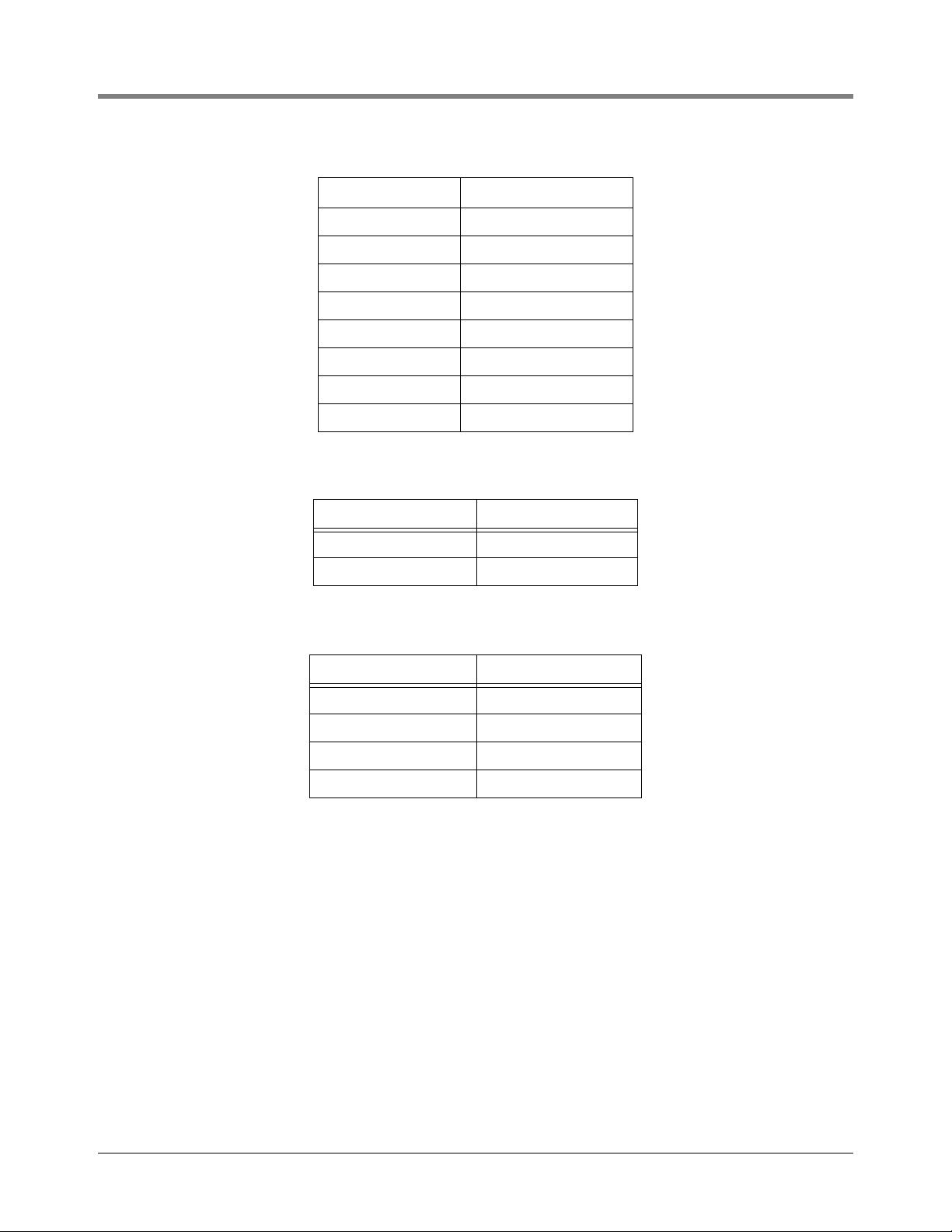
Table 4-6. Tank Probe Database
Data Identification Data Element Name
1 TP_Manufacturer_Id
2TP_Type
4-16
Page 36
Wiring/Miscellaneous For TLS-IB Consoles W/RS-232 & With & W/O IFSF) TLS-IB Specifications
Table 4-6. Tank Probe Database
Data Identification Data Element Name
3 TP_Serial_Nb
4 TP_Model
5 TP_Appl_Software_Ver
32 TP_Status
33 TP_Alarm
64 Product_Level
68 Water_Level
100 TP_Status_Message
Table 4-7. Tank Temperature Table Database
Data Identification Data Element Name
1 Temp_height
2 Temp_value
Table 4-8. Tank Probe Error Code Database
Data Identification Data Element Name
1 TP_Error_Type
3 TP_Error_Total
5 TP_Error_Status
100 TP_Error_Type_Mes
4-17
Page 37
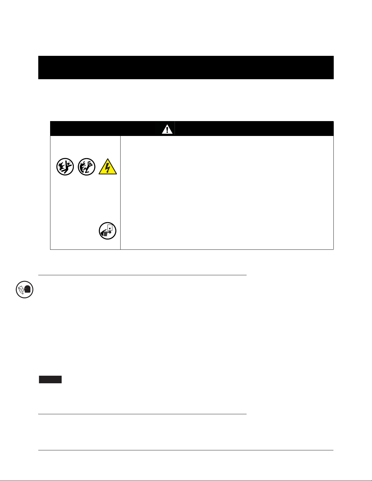
5 Wiring/Miscellaneous For TLS-IB Consoles W/RS-232 &
OFF
NOTICE
RS-485
This section applies only to TLS-IB consoles with the following Form Numbers:
846620-580, 846660-580, 846690-580 (RS-232/RS-485)
WARNING
The equipment is used in location where lethal voltages and explosive vapors
or flammable fuels may be present.
FAILURE TO COMPLY WITH THE FOLLOWING WARNINGS AND SAFETY
PRECAUTIONS COULD CAUSE DAMAGE TO PROPERTY, ENVIRONMENT,
RESULTING IN SERIOUS INJURY OR DEATH.
For this system:
1. Comply with the latest National Electric Code, federal, state, and local
codes, and any other applicable safety codes. In addition, take necessary
precautions during installation, service, and repair to prevent personal
injury, property loss and equipment damage.
2. Refer servicing to trained and qualified personnel only.
3. Substitution of components may impair intrinsic safety.
4. Be sure AC power is “Off” before opening the TLS-IB cover and
connecting probe wires. Do not short any voltage across any barrier
terminal including probes.
Probe Wiring Precautions
To The Installer! You Must Read And Understand This Information. Reference manual number 577013-578 for
additional safety related information.
PROBE WIRING POSITIONS AND LABELING
In all cases, the devices wired to the TLS-IB input terminal blocks must be recorded to prevent improper
replacement during installation or service.
Wiring Assignments
Identify all probe wires according to their terminal block location using the self-adhesive numbering labels
furnished. Accurately record on the circuit directory label (top of I.S. compartment cover plate), the tank number of
each probe as you attach wires to the probe input terminal block.
Once a device has been wired to certain terminals and the system has been programmed,
the wires from that device may not be relocated to other terminals without reprogramming
the system.
Connecting Probes to the TLS-IB
Connect the two color-coded/marked wires from each probe to the appropriate connectors (e.g., Probe 1) of the
Probe Terminal Block as shown in Figure 5-1.
5-1
Page 38

Wiring/Miscellaneous For TLS-IB Consoles W/RS-232 & RS-485 Connecting Probes to the TLS-IB
NOTICE
+
PROBE 6
+
PROBE 5
+
PROBE 4
+
PROBE 3
+
PROBE 2
+
PROBE 1
AVERTISSEMENT
LA SUBSTITUTION DE COMPOSANTS
PEUT COMPROMETTRE LA SECURITE
INTRINSEQUE.
J5
Attach probe cable shield and/or
drain wire to grounding lug
+
PROBE 8
+
PROBE 7
Probe Wiring
Black wire from probe
connects to terminal
White wire from probe
connects to + terminal
Probe Connection
Label
J1
Observe polarity when connecting probe wires!
Connect probe cable shields and drain wires to ground in the TLS-IB only, not at the field junction boxes. Do not
ground both ends of the shield.
AUTO PROBE CONFIGURATION
During a cold boot, the TLS-IB will automatically configure connected probes - CAUTION! For auto
configuration to occur, probes must be connected in sequence, starting at the Probe 1 input and
continuing with no skipped inputs.
For example, if you have 4 probes and you connect them to Probe inputs 1, 2, 3, and 4, auto configuration works
fine. But if you connect them to Probe 1, 3, 5, and 7 auto configuration doesn’t work, resulting in probe out alarms.
Also, the skipped inputs will be unusable.
MANUAL PROBE CONFIGURATION
If you connect probes after the system has been powered they must be manually configured. To configure probes
for the TLS-IB, use the RS-232 “Set Tank Configuration” command 601(see Table 5-3 on page 5-9).
Figure 5-1. Connecting Mag Probe wiring to TLS-IB
5-2
Page 39

Wiring/Miscellaneous For TLS-IB Consoles W/RS-232 & RS-485 Connecting Serial Communication Wiring to the TLS-IB
OFF
J5
Serial Comm Wiring
For RS-232 Network:
Connect TX to (B)
Connect RX to (A)
Connect Signal Ground to (G)
Clear RAM
J3
B
A
G
J11
J12
C
B
A
C
B
A
Move jumper J12 A to the left to clear RAM
Connecting Serial Communication Wiring to the TLS-IB
With AC power switched Off, connect the serial communication wiring to J3 in the TLS-IB as shown in Figure 5-2.
J11/J12 JUMPER POSITIONS (TABLE 5-1)
Jumper(s) Position Result
J11 C, B, A Right RS-232 Serial Communication
J11 C, B, A Left RS-485 Serial Communication
J12C
J12B
Figure 5-2. Connecting Serial Communication Wiring To TLS-IB
Table 5-1. J11/J12 Jumper Positions
Right -------
Left Puts Load Termination on RS-485 circuit
Right --------
Left
Enables serial security code (default is 000000) -
Refer to Serial Interface manual for more
details (see “Related Manuals” on page 1-1)
5-3
Page 40

Wiring/Miscellaneous For TLS-IB Consoles W/RS-232 & RS-485 Connecting Power Wiring to TLS-IB
OFF
OFF
NOTICE
Table 5-1. J11/J12 Jumper Positions
Jumper(s) Position Result
Right --------
J12A
Left
Clears RAM
V-R Tech Support)
( Follow instructions provided by
Connecting Power Wiring to TLS-IB
WARNING
The TLS-IB contains voltages which can be lethal. It is connected to devices
that must be intrinsically safe.
FAILURE TO COMPLY WITH THE FOLLOWING WARNINGS AND SAFETY
PRECAUTIONS COULD CAUSE DAMAGE TO PROPERTY, ENVIRONMENT,
RESULTING IN SERIOUS INJURY OR DEATH.
1. Turn power Off at the circuit breaker connecting the power supply wires.
2. Attach conduit from the power panel to the TLS-IB Power Area
knockouts only (1 on top and 2 on bottom, ref. Figure 2-3 on page 2-6).
1. Pull four wires between the power panel and the TLS-IB; three #14 AWG or larger diameter color-coded
wires for AC line (L), AC neutral (N) and chassis ground; and one #12 AWG (4 mm
2
cross-sectional area)
green and yellow wire for barrier ground.
For international applications, console power should come from a dedicated circuit via a fused, switched, neon
indication spur within one metre of the console position. From an independent 24 hour supply at the distribution panel, run three 2.5 mm
spur. Run three similar wires from the spur to the console location. Run one 4mm
2
(minimum) standard colour coded wires, live, neutral and earth, to the fused
2
wire, colour coded green/
yellow, from the earth bus bar at the distribution panel direct to the console location. Leave at least 1 metre of
free cable for connection to the console.
Use an ohmmeter to check the electrical resistance between the console’s metal case and
the earthing ground wire’s connection at the “known good earth ground” (copper rod driven
into ground, etc.). It should read less than 1 ohm.
2. Open the door of the TLS-IB and connect the four power/ground wires as shown in [Figure 5-3]. Do not
connect the power wires to breaker panel at this time.
5-4
Page 41

Wiring/Miscellaneous For TLS-IB Consoles W/RS-232 & RS-485 Connecting Power Wiring to TLS-IB
C53 C60
L4 L3
+
PROBE 6
+
PROBE 5
+
PROBE 4
+
PROBE 3
+
PROBE 2
+
PROBE 1
J5
+
PROBE 8
+
PROBE 7
Protective Earthing
Conductor (Green and
Yellow) Attach #12AWG
(4 mm
2
) barrier ground
wire to ground lug
Attach chassis ground
wire to ground lug
Probe Data (LED 1)
Power
Power
Side
Power Wiring
Connect neutral wire to upper
terminal of J2 (N). Connect
hot wire to lower terminal (L).
WARNING!
Shock hazard. Do not
touch metal ends of
capacitors C53/C60
or the metal bands
on chokes L4/L3.
J2
LED 1
PWR
N
L
Intrinsically
Safe Side
Figure 5-3. Wiring AC Power To The TLS-IB
5-5
Page 42

Wiring/Miscellaneous For TLS-IB Consoles W/RS-232 & RS-485 Troubleshooting
OFF
OFF
Troubleshooting
This section contains information to help you diagnose system problems. Instructions are included for replacing
the CPU/Power Supply board in the event of a hardware failure and for installing a software upgrade.
At the end of this section you will find a list of specifications for the TLS-IB.
REPLACING THE CPU/POWER SUPPLY BOARD
The CPU/Power Supply board must be replaced if the TLS-IB fails for the reasons below:
• Probe data is not being processed - LED1 is Off (Figure 5-3 on page 5-5), or
• Power LED is Off (Figure 5-3 on page 5-5).
1. Turn Off, tag and lockout power to the system. Attach an anti-static strap to your wrist and to a good ground.
2. Tag and disconnect probe, power, serial comm and overfill alarm relay wiring to the CPU/Power Supply board.
3. The CPU/Power Supply board is secured by two T-15 Torx screws in the top of the board. After removing the
Torx screws, slowly lift up on the board until the lower tabs on the board clear the slots in the bottom of the
TLS-IB, then continue to lift the board out.
4. Replace the CPU/Power Supply board reversing the above steps.
5. Switch On power to the TLS-IB and check your system configuration for proper setup.
SOFTWARE UPGRADE
The TLS-IB firmware upgrade procedure requires the following items:
• A 3-wire serial cable constructed with a connector on one end that matches your laptop’s serial port connector
and 3-wires stripped wires on the other end that will connect to the Serial Comm plug (J3) on the TLS-IB CPU/
Power Supply board (ref. Table 5-2 on page 5-9 for pin outs).
• The TLS-IB.exe program and Firmware Upgrade file - available from Veeder-Root.
• A laptop running Windows 7 or later software.
• The serial interface type, RS-232 or RS-485, must match between the PC and the TLS-IB. (If the PC only has
232 and the IB is configured for 485 you can temporarily use the J11 C,B,A jumpers to configure the TLS-IB to
232 (or vice versa) - see Figure 5-2 on page 5-3.
Upgrade Procedure
1. With AC power switched Off, open the front cover of the TLS-IB and mark each of the three wires connected
to the TLS-IB Serial Comm plug at J3. See Figure 5-2 on page 5-3.
2. Attach the serial cable between your laptop’s serial port connector and the Serial Comm plug on the CPU/
Power Supply board.
3. Turn On power to the TLS-IB.
4. Download the V-R TLSIB Upgrade.exe program onto the laptop.
5. Install the TLSIB_Upgrade program by running TLSIB_Setup.msi or setup.msi.
6. Once installed, the TLSIB_Upgrade.exe program can be found under C:\Program Files (x86)\VeederRoot\TLS-IB. Double click the TLSIB_Upgrade.exe to open the program and display the TLS-IB Firmware
Upgrade window (see Figure 5-4).
7. Click the Select Upgrade File button and browse for the desired firmware upgrade file, e.g., 349876001A.txt. Select the file and click the Open button and it displays in the Firmware File field (see Figure 5-4).
5-6
Page 43
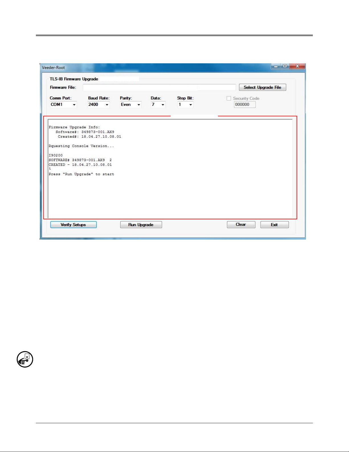
Wiring/Miscellaneous For TLS-IB Consoles W/RS-232 & RS-485 Troubleshooting
Status Window
C:\Program Files (x86)\Veeder-Root\TLS-IB\349876-001A.txt
OFF
CC
Figure 5-4. TLS-IB Firmware Update Screen
8. Select the Comm Port of the connected laptop using the up/down arrows of the Comm Port selector.
9. Select the communication parameters, Baud Rate, Parity, Data and Stop Bit to connect to the TLS-IB
using the up/down arrows for each selection.
10. Use the Security Code checkbox when security code is enabled to connect to the TLS-IB.
11. Select the Verify Setups button to validate all the settings.
a. Verify that the firmware upgrade exists and valid.
b. Verify that the communications are setup correctly.
c. Verify that the TLS-IB Console is ready to accept firmware upgrade.
12. Click the Run Upgrade button to start the firmware upgrade. This button will be activated when setup has
been verified. As the firmware is being upgraded, status messages will be displayed in the Status Window.
13. Select the Clear button to clear status messages written in the Status Window.
14. Select the Exit button to exit the TLSIB_Upgrade program.
15. Turn Off AC power to the TLS-IB.
16. Disconnect the laptop serial cable from J3 on the CPU/Power Supply board.
17. Reconnect the site’s three serial comm wires back into the Serial Com plug, observing their previously marked
positions as you do so.
18. Switch On power to the TLS-IB and check your system configuration for proper setup.
5-7
Page 44

Wiring/Miscellaneous For TLS-IB Consoles W/RS-232 & RS-485 TLS-IB Specifications
TLS-IB Specifications
PHYSICAL SPECIFICATIONS
• Width w/door closed: 188 mm (7.6”) - Width w/door open: 235 mm (9.6”)
• Height: 163 mm (6.7”)
• Depth w/door closed: 50 mm (2.6”), Depth w/door open: 228 mm (9”)
• Weight: 1.8 kg (3.5 lbs)
• The TLS-IB unit contains one CPU/Power Supply board (in unit)
• Removable plug type connections
• Conduit knockouts for intrinsically-safe wiring: 1/2”, 3/4”, and 1” I.P.S. (2 places)
ENVIRONMENTAL SPECIFICATIONS
• TLS-IB storage and operation: indoor, climate controlled
• Operating temperature range: 0 to +40°C
• Storage temperature range: -40 to +74°C
• LVD and EMC compliant
• UL/cUL approved and ATEX approved
ELECTRICAL SPECIFICATIONS
• TLS-IB operating voltage: 120/240 Vac, 2 A max
• Power Supply fuses F1 and F2 are NOT
• Intrinsically-safe circuit for scanning Mag Probes
field replaceable. The rating for both fuses is 2 A, Type T (Time Lag)
SOFTWARE SPECIFICATIONS
• System software upgradeable by a PC program
• RAM clear jumper (Figure 5-2 on page 5-3)
• Factory boot-up mode for self testing
• Supports tank volume reports.
• Supports Density and Density Offset
SERIAL COMMUNICATIONS INTERFACE (SCI)
• RS-232 or RS-485
• Baud rate options: 300, 600, 1200, 2400, 4800, 9600; default 2400
• Parity options: None, Odd, Even; default Even
• Data length options: 8 or 7; default 7
• Number of stop bits options: 1 or 2; default 1
5-8
Page 45

Wiring/Miscellaneous For TLS-IB Consoles W/RS-232 & RS-485 TLS-IB Specifications
WIRING CONNECTIONS
The TLS-IB SCI wiring connections to J3 (on TLS-IB CPU/Power Supply Board, see Figure 5-2 on page 5-3) are
shown in Table 5-2.
Table 5-2. SCI Wiring Connections
TLS-IB J3 Connector Laptop Serial Port Connector
RS-232 Serial Interface
A (receive) TXD (pin 2)
B (transmit) RXD (pin 3)
G (signal ground) GND (pin 5 DB9, pin 7 DB25)
RS-485 Serial Interface
A (receive) A
B (transmit) B
G (signal ground) G
SERIAL INTERFACE COMMANDS
Veeder-Root RS-232 command protocol format applies. Table 5-3 lists the serial commands recognized by the
TLS-IB:
Table 5-3. TLS-IB Serial Commands
Command Description
001 System Reset
002 Clear Power Reset Flag
003 Remote Alarm Reset
201 In-Tank Inventory Report (height, water, and temp only)
205 In-Tank Status Report
214 In-Tank Mass/Density Inventory Report
233 Density Offset History Report
234 In-Tank Mass/Density Inventory Report 2
504 Set RS-232 Security Code
50D Set Print Temperature Compensation Flag
50E Set Temperature Compensation Value
514 Set H-Protocol Height/Volume Format
517 Set System Type & Language Flags (ext. lang. set)
5-9
Page 46

Wiring/Miscellaneous For TLS-IB Consoles W/RS-232 & RS-485 TLS-IB Specifications
Table 5-3. TLS-IB Serial Commands
Command Description
51F Set Euro-Protocol Prefix
545 Set TC Density Enable
601 Set Tank Configuration
604 Set Tank 1 Point Full Height Volume
605 Set Tank 4 point Full and 3/4, 1/2, 1/4 Volumes
606 Set Tank 20 Point Full, 95%, 90%,. . . .Volumes
607 Set Tank Diameter
608 Set Tank Tilt
609 Set Tank Thermal Expansion Coefficient
60A Set Tank Linear Calculated Full Volume
62F Set Mag Probe Float Size
641 Set Density Code
644 Set Probe Density Float Serial Number
645 Set Tank GOST Volume Correction Enable
64C Set Field Density And Temperature
881 Set Communication Port Data
882 Initialize Communication Port Data
883 Set System Measurement Type And Language
902 System Revision Level Report
A01 Probe Type and Serial Number
A02 Probe Factory Dry Calibration Values
A10 Probe Last Sample Buffers
A11 Probe Fast Average Buffers
A12 Probe Standard Average Buffers
5-10
Page 47

Wiring/Miscellaneous For TLS-IB Consoles W/RS-232 & RS-485 TLS-IB Specifications
RESPONSE MESSAGE FORMAT FOR FUNCTION CODE 64C
The Set Field Density And Temperature (64C) Function Code is applicable to TLS-IB Form Numbers 846620580, 846660-580 and 846690-580 only.
Function Code:
64C
Function Type: Set Field Density/Temperature Measurement
Command Format:
Display: <SOH>S64CTTDD.tttTTT.hh<SOH>I64CTT
or: <SOH>S64CTTDD.t,TT.h
Computer: <SOH>s64CTTddddddddtttttttt<SOH>i64CTT
Notes:
1. TT - Tank Number (Decimal, 00=all for inquiry only)
2. DD.ttt - Field Density Measurement (Decimal)
3. TTT.hh - Field Temperature Measurement (Decimal)
4. dddddddd - Field Density Measurement (ASCII Hex IEEE float)
5. tttttttt - Field Temperature Measurement (ASCII Hex IEEE float)
Typical Response Message, Display Format:
<SOH>
I64CTT
T 1
DATE / TIME DENSITY TEMP TC DENSITY TC REF TEMP TC OFFSET
TLS: 721.82 21.94 728.19 15.00 0.00
FIELD: 721.79 22.06 728.26 15.00 0.07
TOTAL:
<ETX>
Typical Response Message, Computer Format:
<SOH>i646TTYYMMDDHHmmTTNNYYMMDDHHmmnnFFFFFFFF...FFFFFFFF
YYMMDDHHmmnnFFFFFFFF...FFFFFFFF&&CCCC<ETX>
Notes:
1. YYMMDDHHmm - Current Date and Time
2. TT - Tank Number (Decimal, 00=all)
3. NN - Number of Records to follow (Hex)
4. YYMMDDHHmm - Date/Time
5. nn - Number of eight character Data Fields to follow (Hex)
6. FFFFFFFF - ASCII Hex IEEE float:
1. TLS Density
2. TLS Temp
7. && - Data Termination Flag
8. CCCC - Message Checksum
5-11
Page 48

For technical support, sales or
other assistance, please visit:
www.veeder.com
 Loading...