

Page 1

Install, Setup, & Operation Manual
Pressure Management Control
For VST Processors
Manual No: 577013-801 • Revision: E
Page 2

Notice
Veeder-Root makes no warranty of any kind with regard to this publication, including, but not limited to, the implied warranties of
merchantability and fitness for a particular purpose.
Veeder-Root shall not be liable for errors contained herein or for incidental or consequential damages in connection with the furnishing,
performance, or use of this publication.
Veeder-Root reserves the right to change system options or features, or the information contained in this publication.
This publication contains proprietary information which is protected by copyright. All rights reserved. No part of this publication may be
photocopied, modified or translated to another language without the prior written consent of Veeder-Root. Contact TLS Systems
Technical Support for additional troubleshooting information at 800-323-1799.
DAMAGE CLAIMS / LOST EQUIPMENT
Thoroughly examine all components and units as soon as they are received. If any cartons are damaged or missing, write a complete
and detailed description of the damage or shortage on the face of the freight bill. The carrier's agent must verify the inspection and sign
the description. Refuse only the damaged product, not the entire shipment.
Veeder-Root must be notified of any damages and/or shortages within 30 days of receipt of the shipment, as stated in our Terms and
Conditions.
VEEDER-ROOT’S PREFERRED CARRIER
1. Contact Veeder-Root Customer Service at 800-873-3313 with the specific part numbers and quantities that were missing or
received damaged.
2. Fax signed Bill of Lading (BOL) to Veeder-Root Customer Service at 800-234-5350.
3. Veeder-Root will file the claim with the carrier and replace the damaged/missing product at no charge to the customer. Customer
Service will work with production facility to have the replacement product shipped as soon as possible.
CUSTOMER’S PREFERRED CARRIER
1. It is the customer’s responsibility to file a claim with their carrier.
2. Customer may submit a replacement purchase order. Customer is responsible for all charges and freight associated with
replacement order. Customer Service will work with production facility to have the replacement product shipped as soon as
possible.
3. If “lost” equipment is delivered at a later date and is not needed, Veeder-Root will allow a Return to Stock without a restocking fee.
4. Veeder-Root will NOT be responsible for any compensation when a customer chooses their own carrier.
RETURN SHIPPING
For the parts return procedure, please follow the appropriate instructions in the "General Returned Goods Policy” pages in the
"Policies and Literature" section of the Veeder-Root North American Environmental Products price list. Veeder-Root will not accept
any return product without a Return Goods Authorization (RGA) number clearly printed on the outside of the package.
FCC INFORMATION
This equipment complies with the requirements in Part 15 of the FCC rules for a Class A computing device. Operation of this
equipment in a residential area may cause unacceptable interference to radio and TV reception requiring the operator to take whatever
steps are necessary to correct the interference.
INSTALLATION IN THE STATE OF CALIFORNIA
Please refer to the California Air Resources Board Vapor Recover Certification Phase II EVR Executive Order web site
(www.arb.ca.gov/vapor/eo-evrphaseII.htm) for the latest manual revisions pertaining to VR 203 (VST Phase II EVR System).
©Veeder-Root 2012. All rights reserved
.
ii
Page 3

Introduction
Site Requirements ............................................................................................................1
Contractor Certification Requirements ..............................................................................1
Related Manuals ...............................................................................................................2
Safety Precautions ............................................................................................................2
Installation
Installing TLS Console Modules - General Notes .............................................................3
Circuit Directory........................................................................................................4
Vapor Pressure Sensor ....................................................................................................4
Smart Sensor Interface Module ........................................................................................4
NVMEM203 Board ............................................................................................................5
Probe Interface Module ....................................................................................................5
I/O Combination or 4-Relay Module ..................................................................................5
Multiport Card for Vapor Processor Communication ........................................................5
TLS Console with VST ECS Membrane Processor ..........................................................5
Setup
Introduction .......................................................................................................................7
Smart Sensor Setup .........................................................................................................7
Output Relay Setup - VST ECS Membrane Processor & VST Green Machine ................8
PMC Setup .......................................................................................................................9
Table of Contents
Operation
Alarms .............................................................................................................................10
Overview of TLS console Interface.........................................................................10
Warning Posting .....................................................................................................11
Alarm Posting .........................................................................................................11
PMC Alarm Summary .....................................................................................................12
PMC Status Report .........................................................................................................13
Viewing PMC Reports Via RS-232 Connection ..............................................................13
Connecting Laptop to Console ...............................................................................13
Connecting Laptop to Console ...............................................................................14
Sending Console Commands.................................................................................17
Diagnostics
Automatic Control ...........................................................................................................22
Manual control ................................................................................................................22
PMC Diagnostic Menu ....................................................................................................22
iv
Page 4

Figures
Table of Contents
Figure 1. TLS console Interface Module Bays...........................................................3
Figure 2. VST ECS Membrane Processor or VST Green Machine
Connections to TLS Console......................................................................6
Figure 3. Smart Sensor Setup...................................................................................7
Figure 4. Output Relay Setup for VST ECS Membrane Processor...........................8
Figure 5. Output Relay Setup Printout Examples for TLS Console
Controlled Processor..................................................................................8
Figure 6. PMC Setup.................................................................................................9
Figure 7. TLS console alarm interface.....................................................................10
Figure 8. TLS console warning example .................................................................11
Figure 9. TLS console alarm example.....................................................................11
Figure 10. PMC Status Report ..................................................................................13
Figure 11. Connecting laptop to TLS console for serial communication ...................14
Figure 12. Connection Description window ...............................................................15
Figure 13. Connect To window..................................................................................15
Figure 14. Console comm port settings printout example .........................................16
Figure 15. HyperTerminal main window....................................................................17
Figure 16. Vapor Processor Status Report Details - Serial to PC Format.................18
Figure 17. Vapor Processor Runtime Diagnostic Report - Serial to PC Format........19
Figure 18. Percent Hydrocarbon Diagnostic Report - Serial to PC Format...............20
Figure 19. Priority Alarm History Report - Serial to PC Format.................................20
Figure 20. Non-Priority Alarm History Report - Serial to PC Format .........................21
Figure 21. PMC Diagnostic Menus............................................................................22
Tables
Table 1. Related Manuals .......................................................................................2
Table 2. TLS-350 (PMC) Alarm Troubleshooting Summary ..................................12
Table 3. Serial Commands for PMC Diagnostic Reports ......................................18
v
Page 5

Introduction
This manual provides instructions to install, setup, and operate the components of Veeder-Root Pressure
Management Control (PMC) equipment. The PMC feature is an option for the TLS console platform, and as such,
many of the installation/setup/operation instructions for non-PMC specific tasks are covered in TLS-3XX supplied
literature. Do not use this manual when PMC is installed with ISD. Use the ISD Setup & Operation Manual,
577021-800.
Site Requirements
Below are the requirements for all PMC installations:
• V-R TLS-350R/EMC w/BIR, TLS-350 Plus/EMC Enhanced, TLS-350/EMC and ProMax consoles with ECPU2
- install as per TLS-3XX Site Prep manual, setup following instructions in TLS-3XX System Setup Manual.
• A flash memory board (NVMEM203) for PMC software storage - installed on the ECPU2 board in place of the
console’s 1/2 Meg RAM board - install as per TLS-350 Series Board and Software Replacement Manual, no
setup required.
• Smart Sensor Module and Vapor Pressure Sensor. Install and connect following instructions in the Vapor
Pressure Sensor installation Guide.
• Multiport card connected to a hydrocarbon sensor module installed according to processor manufacturers
specifications.
• A 4-Relay or I/O Combination Module to control the vapor processor motor and setup as instructed in this
manual.
• An RS-232 Port will be available for use by contractor or government inspectors.
Contractor Certification Requirements
Veeder-Root requires the following minimum training certifications for contractors who will install and setup the
equipment discussed in this manual:
Installer (Level 1) Certification: Contractors holding valid Installer Certification are approved to perform wiring and
conduit routing; equipment mounting; probe, sensor and carbon canister vapor polisher installation; wireless equipment
installation; tank and line preparation; and line leak detector installation.
ATG Technician (Level 2/3 or 4) Certification: Contractors holding valid ATG Technician Certifications are approved
to perform installation checkout, startup, programming and operations training, system tests, troubleshooting and
servicing for all Veeder-Root Series Tank Monitoring Systems, including Line Leak Detection. In addition, Contractors
with the following sub-certification designations are approved to perform installation checkout, startup, programming,
system tests, troubleshooting, service techniques and operations training on the designated system.
• Wireless 2
•Tall Tank
VR Vapor Products Certification: Contractors holding a certification with the following designations are approved to
perform installation checkout, startup, programming, system tests, troubleshooting, service techniques and operations
training on the designated system.
• ISD – In Station Diagnostics
• PMC – Pressure Management Control
• CCVP - Veeder-Root Vapor Polisher
• Wireless – ISD/PMC Wireless
• A current Veeder-Root Technician Certification is a prerequisite for the VR Vapor Products course.
Warranty Registrations may only be submitted by selected Distributors.
1
Page 6
Introduction Related Manuals
OFF
OFF
Related Manuals
The manuals in Table 1 below are shipped with the equipment on the V-R Tech Docs CD-ROM and will be needed
to install specific equipment.
Table 1. Related Manuals
V-R Manual Part Number
TLS-3XX Site Prep Manual 576013-879
Vapor Pressure Sensor For Vent Stacks Installation Guide
(For Sensor P/N 861190-X0X)
Pressure Sensor Installation Guide
(For Sensor P/N 331946-001)
TLS-3XX Series Consoles System Setup Manual 576013-623
TLS-3XX Series Consoles Operator’s Manual 576013-610
Serial Comm Modules Installation Guide 577013-528
TLS-350 Series Board and Software Replacement Manual 576013-637
577014-019
577013-797
Safety Precautions
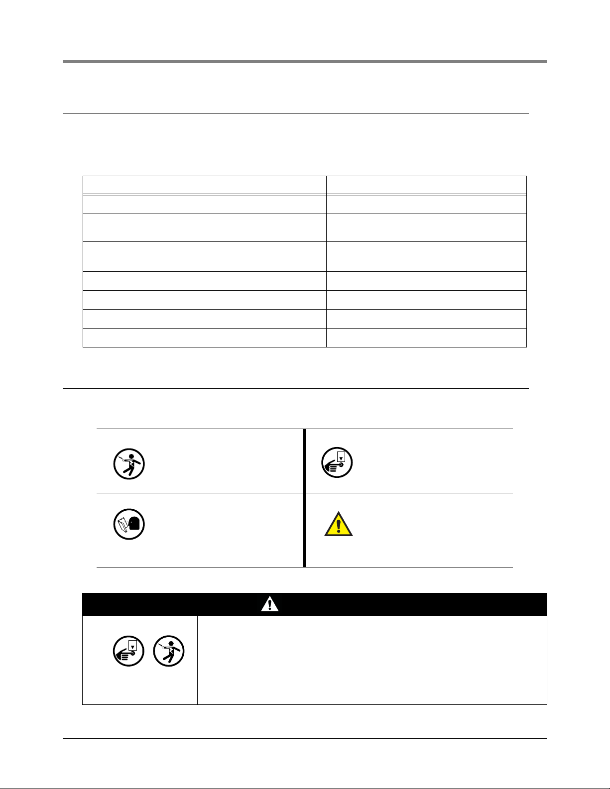
The following symbols may be used throughout this manual to alert you to important safety hazards.
ELECTRICITY
High voltage exists in, and is supplied to, the device. A potential
shock hazard exists.
READ ALL RE LATED MANUALS
Knowledge of all related procedures before you begin work is
important. Read and understand
all manuals thoroughly. If you do
not understand a procedure, ask
someone who does.
TURN POWER OFF
Live power to a device creates a
potential shock hazard. Turn Off
power to the device and associated accessories when servicing
the unit.
WAR N ING
Heed the adjacent instructions to
avoid equipment damage or personal injury.
WARNING
The console contains high voltages which can be lethal. It is also connected to
low power devices that must be kept intrinsically safe.
Turn power Off at the circuit breaker. Do not connect the console AC power
supply until all devices are installed.
FAILURE TO COMPLY WITH THE FOLLOWING WARNINGS AND SAFETY
PRECAUTIONS COULD CAUSE DAMAGE TO PROPERTY, ENVIRONMENT,
RESULTING IN SERIOUS INJURY OR DEATH.
2
Page 7
Installation
OFF
console\350rjmods.eps
Intrinsically
Safe Bay
Permissible
Modules
(Limit 8
per console)
1
2
3
4
5
6
7
8
16
15
14
13
12
11
10
9
12 34
I.S. Bay
Slot Numbers
Power Bay
Slot Numbers
Comm Bay
Slot Numbers
Comm Cage*
This section discusses the installation and wiring of the hardware required to enable the TLS console to perform
pressure management of the site’s gasoline vapor processor equipment:
• Vapor Pressure Sensor
• Smart Sensor Interface Module
• NVMEM203 board
• Multiport Card
• 4-Relay or I/O Combination Module
All field wiring, its type, its length, etc., used for TLS console sensors must conform to the requirements outlined in
the Veeder-Root TLS-3XX Site Prep manual (P/N 576013-879) and to additional field wiring requirements
specified in related connected components, such as for Pressure Sensors.
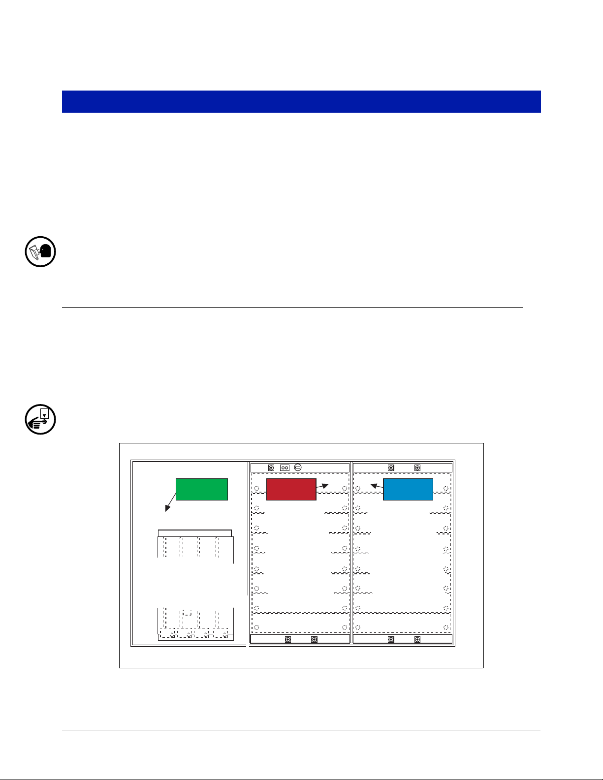
Installing TLS Console Modules - General Notes
TLS consoles have three bays in which interface modules can be installed; Comm bay, Power bay and IntrinsicallySafe bay (ref. Figure 1). Probe Interface modules and Smart Sensor modules are installed in the Intrinsically-Safe
bay and the Mod Bus module is installed in the Comm bay.
In all cases, the position of the modules, their respective connectors and the devices wired to the
connectors must be recorded to prevent improper replacement during installation or service. A circuit
directory for Power and I.S. bay Interface Modules is adhered to the back of the right-hand door for
this purpose.
Switch off power to the TLS console before you install modules and connect sensor wiring.
Figure 1. TLS console Interface Module Bays
3
Page 8

Installation Vapor Pressure Sensor
OFF
CAUTION! During programming, module positions and the devices wired to each module are identified and stored
in memory. If a connector is removed and reinstalled on a different module after programming, or if an entire module
with its connector is removed and reinstalled in a different module slot, the TLS console will not identify correctly
the data being received.
Module Position
1. Record on the circuit directory the type of module in each slot location.
2. If a system contains multiple modules of a single type (i.e., two Smart Sensor Modules), they may be swapped
between their respective slot locations, however, the connectors must remain with their original locations,
not with the original modules.
Connector Position
1. Identify all connectors according to their slot location using the self-adhesive numbering labels furnished with
each module. Accurately record on the circuit directory the location of each device wired to the connector as
you attach wires to the module.
2. Once a device has been wired to certain terminals on a connector and the system has been programmed, the
wires from that device may not be relocated to other terminals without reprogramming the system.
Grounding Probe and Sensor Shields
Connect probe and sensor cable shields to ground at the console only. Do not ground both ends of the shield.
CIRCUIT DIRECTORY
A circuit directory is adhered to the inside of the right-hand door. It should be filled out by the installer as the
module’s connectors are being wired.
The following information should be recorded for each slot:
• Module Type: record what type of module has been installed in the slot, e.g., Smart Sensor Module.
• Position Record: record the physical location and/or type of device wired to each terminal of the module
connector in the slot, e.g., VPS: FP1&2.
Vapor Pressure Sensor
Install one vapor pressure sensor as detailed in the applicable Pressure Sensor Installation Guide shown in Table 1.
Smart Sensor Interface Module
The Smart Sensor Interface Module 8 input or 7 input w/embedded pressure versions monitor the Vapor Pressure
Sensor (VPS) inputs.
Switch off power to the TLS console while you install modules and connect sensor wiring.
Open the right door of the console and slide the necessary Smart Sensor modules into empty I.S. Bay slots.
Connect the field wiring from the sensor following instructions in the Vapor Pressure Sensor manual. Setup the
Smart Sensor module(s) following instructions in this manual.
4
Page 9

Installation NVME M203 Board
NVMEM203 Board
Verify that a NVMEM203 board is installed in the TLS console (ref. Figure 2-7 in the V-R TLS-3XX Series
Consoles Troubleshooting Manual P/N 576013-818, Rev Q or later). This board contains flash EEPROM and
RAM needed to run PMC software. No setup is required.
Probe Interface Module
Verify that a Probe Interface Module(s) is installed (Intrinsically-Safe bay) and that a Mag probe is in each gasoline
tank and is connected to the module(s). Program the Mag probes following instructions in the TLS-3XX System
Setup manual.
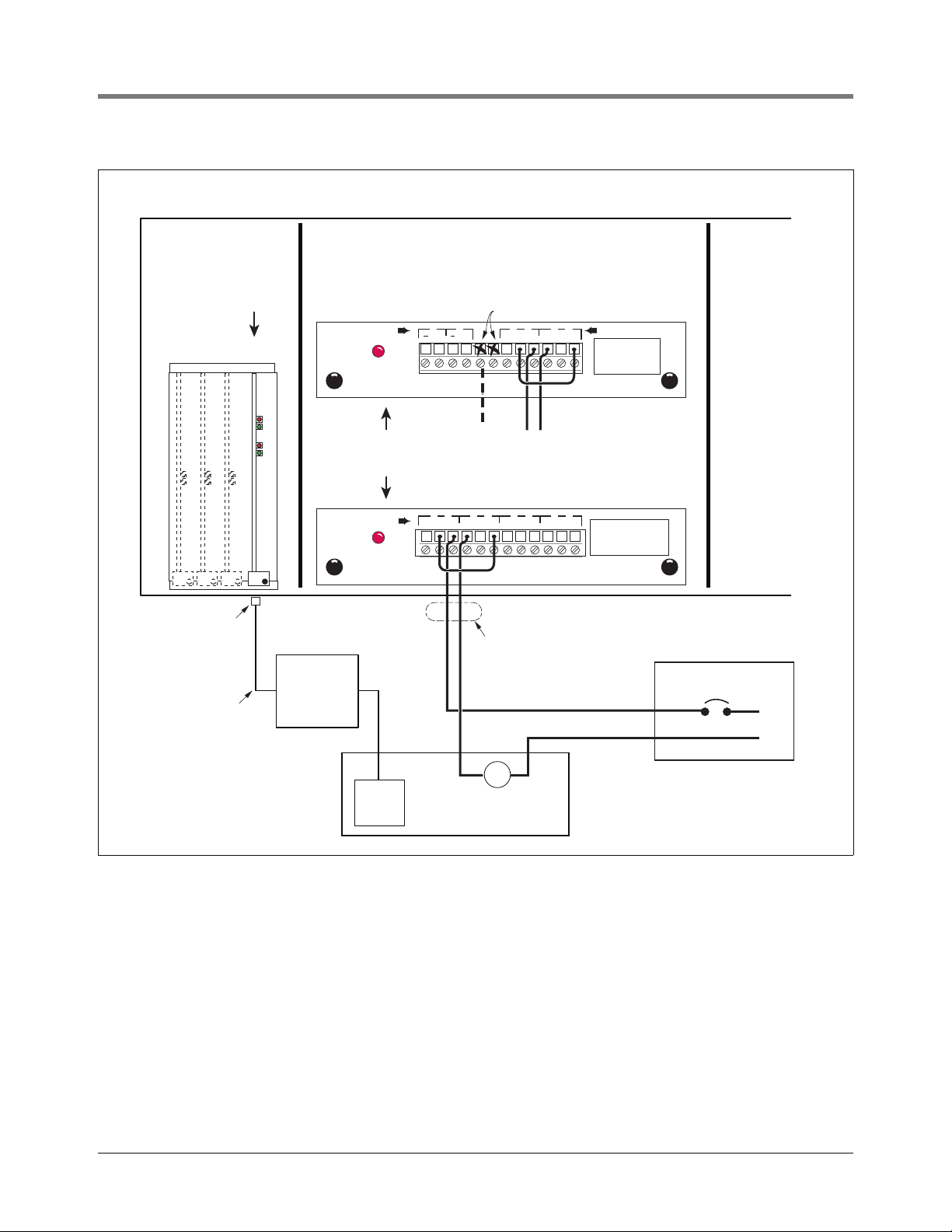
I/O Combination or 4-Relay Module
Connect the vapor processor motor control relay to two relays on either the 4-Relay or I/O Combination module as
shown in Figure 2.
Multiport Card for Vapor Processor Communication
A Multiport card is needed for RS-485 communication with the TLS console and is required with VST ECS
membrane processor installations. Verify that a Multiport card is installed in slot 4 of the card cage in the
communications bay of the TLS console (ref. Figure 2). When installing this card, refer to the V-R Serial Comm
Modules Installation Guide (577013-528) for instructions. Connect this card to the vapor processor as shown in
Figure 2. Program the card as instructed in this manual.
TLS Console with VST ECS Membrane Processor
Figure 2 shows the interconnection wiring between a TLS console and a VST ECS Membrane Processor.
5
Page 10
Installation TLS Console with VST ECS Membrane Processor
Motor Control
Relay
Multiport
Card
HC
Sensor
Modbus
Protocol
RS-485
TLS Console
Power Panel
VST ECS Membrane Processor
and VST Green Machine
RJ-45
Connector
COMMUNICATION BAY
POWER BAY I.S. BAY
RELAY
RELAY RATINGS
Form C Contacts
120 VAC, 2A Max; or
24 VDC, 2A Max.
1 2
4-RELAY OUTPUT MODULE
NC NO C
1
NC NO C
2 3
NC NO C3NC NO C
44
Rigid Conduit (enters
Console through a
Power Bay knockout)
INPUT
RELAY RATINGS
Form C Contacts
120 VAC, 2A Max; or
24 VDC, 2A Max.
I/O COMBINATION MODULE
3
NC NO C3NC NO C
44
+ +
1 2
RELAY
L1
115 Vac Breaker
Wire as shown
on 4-Relay module
N
Not Used
Use either
module
801-5.eps
12 34
HC Sentry
Interface
Module
Figure 2. VST ECS Membrane Processor or VST Green Machine Connections to TLS Console
6
Page 11
Setup
C
Change
B
Backup
E
Enter
S
Step
M
Mode
F
Function
Advance Cursor
Print
T P
1
2
Key press
sequence
Repress until
desired message
appears in display
Key Legend
Tank
Sensor
S
801-7.eps
C
C
E
S
E
S
E
S
P
F
SMARTSENSOR SETUP
PRESS <STEP> TO CO NTINUE
SETUP MODE
PRESS <FUNCTION> TO CONT
M
C
C
Select sensor category
(e.g., Vapor Pressure Sensor)
Press this button and select type.
Note: User can only change assigment
if device has not identified itself. If
actual device disagrees with assigned
type, actual type overrides assigned
type.
The first of the installed SS modules appears
in this display. If this is not the module to
which the Vapor Pressure Sensor (VPS) is
connected, press the Tank/Sensor button to
select another SS module.
Press once and the first position blinks. If
the VPS is connected to the first position of
the SS module, press this button again and
the X changes to a 1.
Press this button and
the X changes to the
number of the VPS
connection (2-8).
Prints out a copy of the
SmartSensor Setup.
See example at right.
Press this button and enter a
label for the sensor, e.g., VP
Sensor.
If the VPS is connected to a position other
than the first, continue to press this button
until the VPS connected position blinks.
SMARTSENSOR SETUP
---------------------S01:VP SENSOR
CATEGORY VAPOR PRESSURE
S1: SELECT SS CATEGORY
UNKNOWN
SS CONFIG - MODULE 1
SLOTX - X X X X X X X X
ENTER SMARTSENSOR LABEL
sX:
Introduction
This section describes how to perform PMC setup using the TLS console’s front panel buttons and display. The
procedures in this manual follow standard TLS console setup programming input, i.e., keypad/display interaction. If
necessary, refer to Section 2 of the TLS-3XX System Setup manual (P/N 576013-623) to review entering data via
the front panel keypads.
All PMC-related equipment must be installed in the site and connected to the TLS console prior to beginning the
setups covered in this section. As with all TLS connections, you cannot change sensor wiring or module slots after
programming or the console may not operate properly. Reference the section entitled “Connecting Probe/Sensor
Wiring to Consoles” in the TLS-3XX Site Prep and Installation manual (P/N 576013-879) for rewiring precautions.
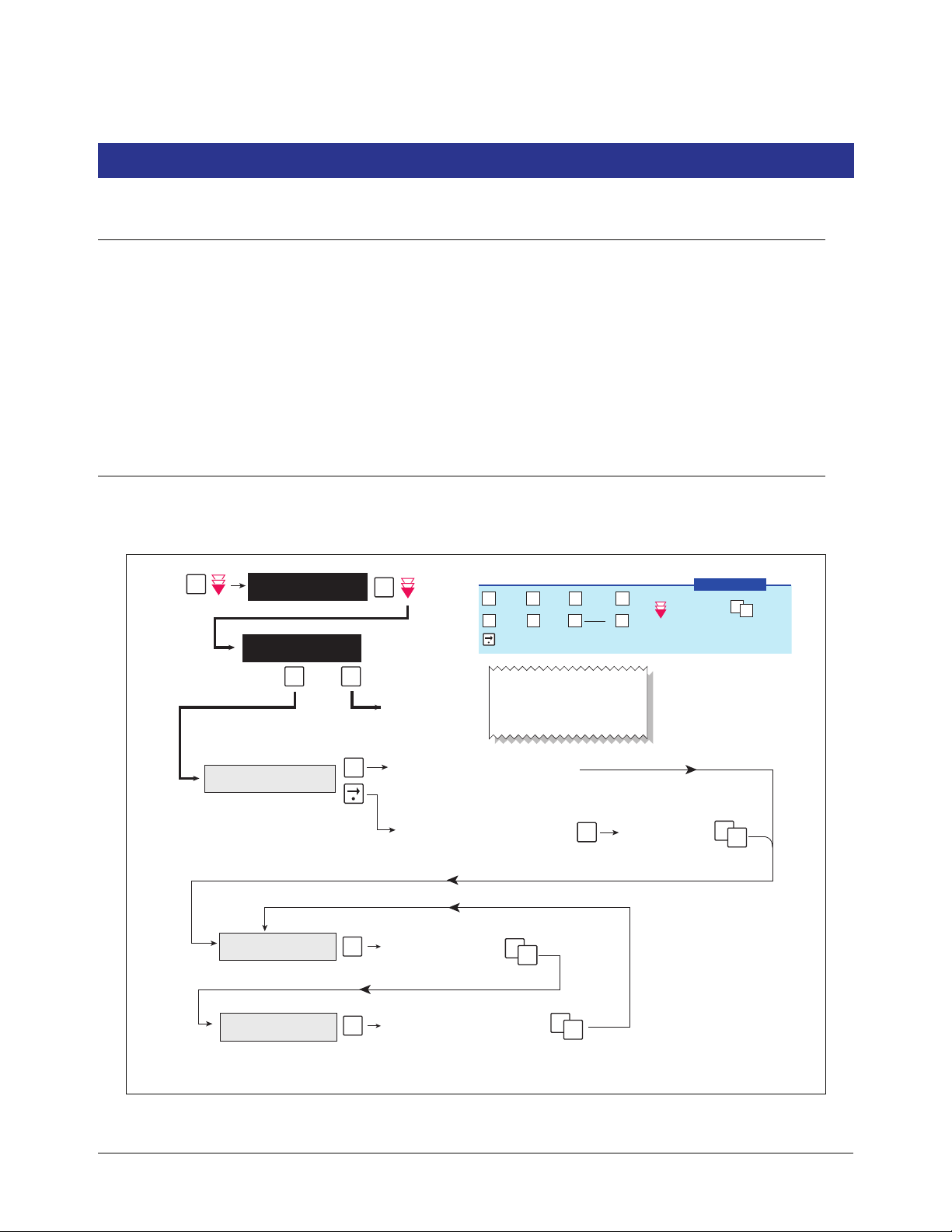
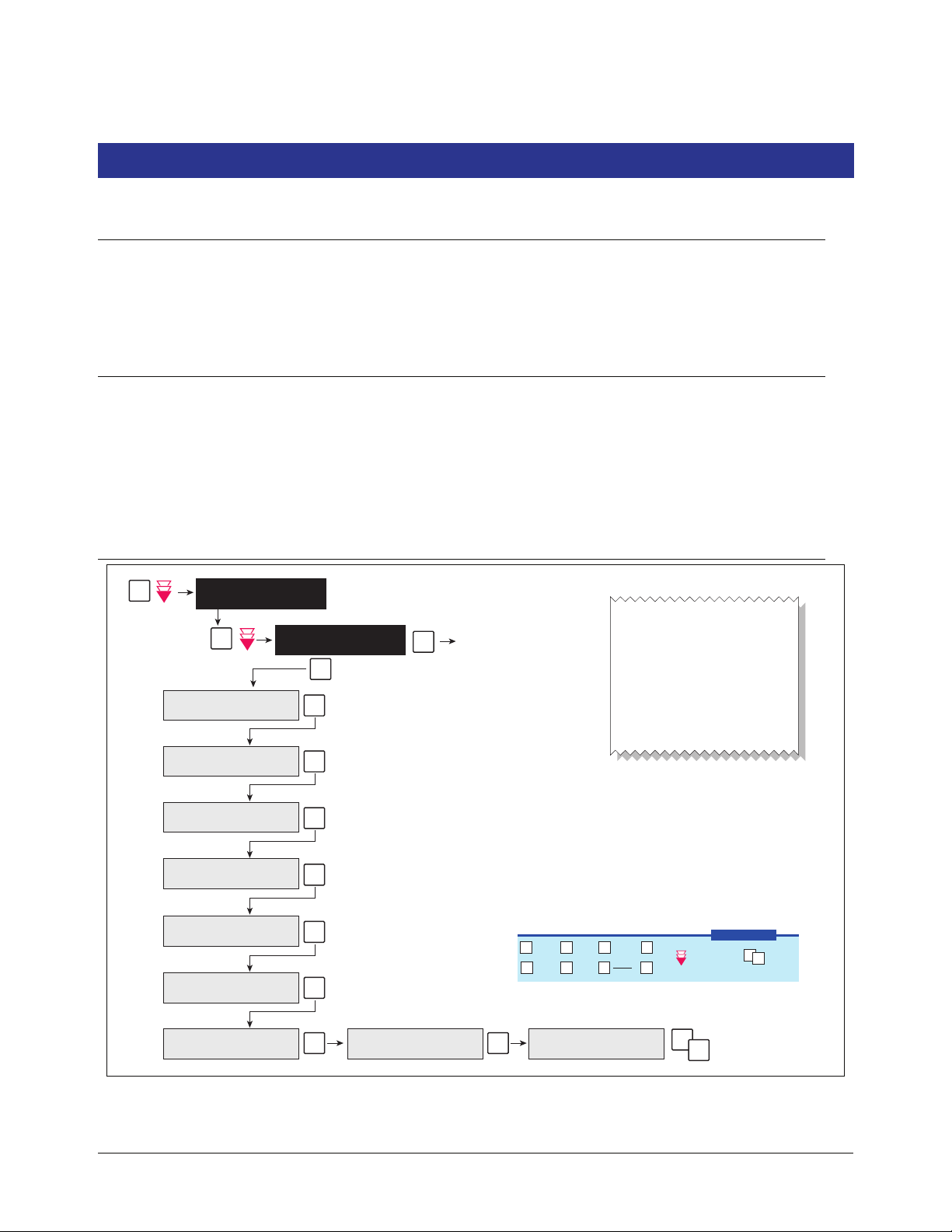
Smart Sensor Setup
The Smart Sensor Interface Module is installed in the Intrinsically-Safe bay of the TLS console. This module
monitors the Vapor Pressure Sensor. Figure 3 diagrams the Smart Sensor setup procedure.
Figure 3. Smart Sensor Setup
7
Page 12

Setup Output Relay Setup - VST ECS Membrane Processor & VST Green Machine
SETUP MODE
PRESS <FUNCTION> TO C ONT
OUTPUT RE LAY SETU P
PRESS <STEP> TO CO NTINUE
Prints out a copy of the Output Relay Setup entries. See examples in figure below.
In our example R1 is the relay used by PMC to control the processor, R2 is the relay
used to shutoff the processor when the High Product Alarm is active.
M
P
S
S
S
F
ENTER RELAY DESIGNATION
R1 :
R1 : SELE CT RELAY TYPE
STANDARD
R2 : SELE CT RELAY TYPE
STANDARD
R2 : SELE CT TANK
NONE
R1 : SELECT ORIENTATION
NORMALLY OPEN
R2 : SELE CT ORIENTATION
NORMALLY OPEN
R2 : VP SHUTOFF
IN-TANK ALARMS: NO
Press Change
and enter
VAPOR PROCESSOR
for the relay
Note: If using an I/O
Combo Module
there are just 2 slots.
801-6.eps
C
Press Change
and enter
VP SHUTOFF
for the relay
C
C
E
S
E
S
E
S
RELAY CONFIG - MODULE X
SLOT # — X, X, X, X
T
ENTER RELAY DESIGNATION
R2 :
S
S
C
E
S
Vapor Processor
Standard
C
E
S
Standard
Vapor Processor
C
E
S
E
S
Normally Open
Normally Closed
Normally Closed
Normally Open
C
E
S
YES
NO
R2 : IN-TANK ALAR MS
HI PRODUCT: NO TANKS
C
E
S
ALL TANKS
NO TANKS
C
Change
B
Backup
M
Mode
E
Enter
S
Step
F
Function Print
T P
1
2
Key press
sequence
Repress until
desired message
appears in display
Key Legend
Tank
Sensor
Press once and
the 2nd X changes
to a 2.
C C
Press once and the first
position blinks, press
again and the X changes
to a 1.
Press once and
the second
position blinks
OUTPUT RELAY SETUP
----------------------
R 1: VAPOR PROCESSOR
TYPE:
VAPOR PROCESSOR
NORMALLY OPEN
- NO ALARM ASSIGNMENTS -
OUTPUT RELAY SETUP
----------------------
R 2: VP SHUTOFF
TYPE:
STANDARD
NORMALLY CLOSED
IN-TANK ALARMS
ALL HIGH PRODUCT ALARMS
isd-evr\ortlscntrlvpsetprt.eps
Output Relay Setup - VST ECS Membrane Processor & VST Green Machine
The Output Relay setup programs an output relay so that the TLS console can switch a controlled vapor processor
on and off as shown in Figure 4.
Figure 5 shows example setup printouts of the Output Relays setup.
Figure 5. Output Relay Setup Printout Examples for TLS Console Controlled Processor
Figure 4. Output Relay Setup for VST ECS Membrane Processor
8
Page 13

Setup PMC Setup
PMC SETUP
PRESS <STEP> TO CONTIN UE
SETUP MODE
PRESS <FUN CTION> TO CONT
VAPOR PROCESSOR TYPE
NONE
INCHES -0.20
INCHES -0.60
M
P
F
TURN OFF VAPOR PROCESSOR
TURN ON VAPOR PROCESSOR
HYDROCARBON SELECT
PRESS <ENTER>
DUTY CYCLE LIMIT
xx.xx %
SET ANALYSIS TIME
PRESS <ENTER>
S
SET TEST START TIME
TIME: hh:mm
SET POST DELAY DURATION
DELAY MINUTES: mmm
801-4.eps
PMC SETUP
---------------------PMC VERSION: 01.04
VAPOR PROCESSOR TYPE
VST ECS PROCESSOR
PROCESSOR CONTROL LEVEL:
FULL
ON: -0.200 INCHES
OFF:-0.600 INCHES
OVER PRESSURE LIMIT
xx.xx PERCENT%
EFFLUENT EMISSIONS LIMIT
0.649 LB/1KG
DUTY CYCLE LIMIT
xx.xx
ANALYSIS TIMES
TIME 11:59 PM
DELAY MINUTES 1
Prints out a copy of the
PMC Setup entries. See
Example at right.
Range checking is enforced:
0<xx.xx<100
Default: 75%
S
C
S
S
S
S
S
S
E
E
Sets vapor processor Off point.
Range: -8<Off setting<On setting.
For more info see example at right.
VST ECS PROCESSOR
VST GREEN MACHINE
Sets vapor processor On point.
Range: Off setting<On setting<+3.
For more info see example at right.
Vapor Processor On/Off example
P/V valve opens
Absolute
Range
(IWC)
Ullage vapor pressure
+3
-8
+0.2
-0.2
0
Turn On
vapor processor
Turn Off
vapor processor
Use <ENTER> key to make selection
MODBUS Sensor default enabled
This menu appears for
VST ECS Membrane
Processor only
Use <CHANGE> key to enter.
Default Start time - 11:59 PM
Use <CHANGE> key to enter.
0<delay<=720
Default: =001
NOTE: If delay minutes = 0, the results
will be posted as soon as they become
available, else mmm minutes after start
time.
Data collected 5 minutes before the
Start of Test time is omitted from test.
C
Change
B
Backup
M
Mode
E
Enter
S
Step
F
Function Print
T P
1
2
Key press
sequence
Repress until
desired message
appears in display
Key Legend
Tank
Sensor
S
VST ECS Membrane
Processor only
ECS Membrane
Green Machine
+0.20
+0.20
-0.20
-2.00
Processor turn on turn off
E C
E
S
Press Tank to view the next pressure
sensor, change status as required.
T
S
PRESSURE SENSOR SELECT
PRESS <ENTER>
LABEL: (PS label)
SN#: (10 char) DISABLED
LABEL: (PS label)
SN#: (10 char) ENABLE D
S
NONE
PMC Setup
Figure 6 diagrams the PMC setup programming.
Figure 6. PMC Setup
9
Page 14

Operation
MODE
BACKUP
FUNCT-
TION
PRINT CHANGE STEP
PAPER
FEED
ENTER
QZ.
ABC
DEF
GHI JKL MNO
PRS TUV WXY
ALARM
TEST
TANK
SENSOR
,
+/-
0
789
123
456
consoles\qh\1.eps
ALARM
WARNING
POWER
16-01-98 11:23:17 AM
ALL FUNCTIONS NORMAL
Liquid Crystal Display
(showing normal operating display)
Alarm Indicator Light
Warning Indicator Light
Power Indicator Light
Operating Keys Alphanumeric Keys
Alarms
OVERVIEW OF TLS CONSOLE INTERFACE
The TLS console is continuously monitoring the vapor recovery system and PMC sensors for alarm conditions.
During normal operation when the TLS console and monitored PMC equipment is functioning properly and no
alarm conditions exist, the "ALL FUNCTIONS NORMAL" message will appear in the system status (bottom) line
of the console display, and the green Power light will be On (see Figure 7).
If an alarm condition occurs the system displays the condition type and its location. If more than one condition
exists, the display will continuously cycle through the appropriate alarm messages. The system automatically prints
an alarm report showing the alarm type, its location and the date and time the alarm condition occurred.
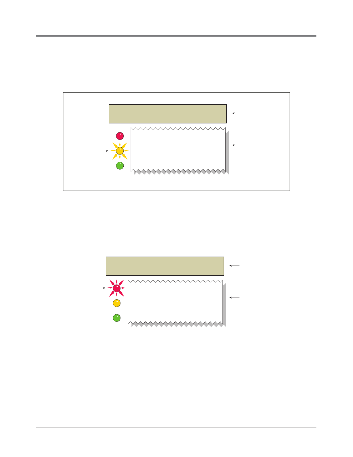
Warning and alarm posting causes the TLS console-based system to activate warning or failure indicator lights, an
audible alarm, and an automatic strip paper printout documenting the warning or alarm.
Figure 7. TLS console alarm interface
10
Page 15
Operation Alarms
WARNING POSTING
Displayed messages alert you to the type of warning. Printed messages show the type of warning and the time the
warning was posted (see Figure 8). Warnings are logged into the Non-Priority Alarm History in the TLS.
MMM DD, YYYY HH:MM XM
VP EMISSIONS WARN
TLS console
display message
---- PMC ALARM --- VP EMISSIONS WARN
TLS console
warning light
flashes
Figure 8. TLS console warning example
MMM DD, YYYY HH:MM XM
isd-evr\pmc\fig5.eps
TLS console
printout message
ALARM POSTING
Displayed Messages alert you to the type of alarm. Printed messages show the type of alarm and the time the
alarm was posted. Alarm example in Figure 9. PMC Alarms are logged into the Priority Alarm History in the TLS.
MMM DD, YYYY HH:MM XM
VP EMISSIONS FAIL
TLS console
display message
TLS console
alarm light
flashes
---- PMC ALARM --- VP EMISSIONS FAIL
MMM DD, YYYY HH:MM XM
Figure 9. TLS console alarm example
11
isd-evr\pmc\fig6.eps
TLS console
printout message
Page 16

Operation PMC Alarm Summary
PMC Alarm Summary
Table 2 contains a listing of the PMC generated alarms including their displayed message and cause. TLS
Console PMC alarms may be interspersed amongst non-PMC alarms, please see TLS-350 Series manuals for
more information.
Table 2. TLS-350 (PMC) Alarm Troubleshooting Summary
Displayed Message Description
VP EMISSION WARN Mass emission exceeded the certified
VP EMISSION FAIL 2nd Consecutive mass emission
PMC SETUP FAIL PMC is not configured or missing
VP DUTY CYCLE WARN
VP DUTY CYCLE FAIL
PMC SE NSOR FAULT Component used by PMC has failed
1
daily threshold
failure
components.
1
Duty cycle exceeds 18 hours per day
0r 75% of 24 hours
2nd Consecutive Duty Cycle Failure Red
or reported an error condition. See
Troubleshooting section for complete
description of sensors and associated
conditions that can cause a sensor
fault.
Light
Indicator Suggested Troubleshooting
Yellow • Troubleshooting Guide
Red
Red • Troubleshooting Guide
Yellow • Troubleshooting Guide
Red Check for Smart Sensor Device
www.vsthose.com.
• Exhibit 8
• Exhibit 9
www.vsthose.com
• See ISD Troubleshooting Guide,
P/N 577013-819
• Exhibit 8
• Exhibit 9
www.vsthose.com.
• TLS-350 PMC Setup Procedure
• Exhibit 4
• Exhibit 9
• Exhibit 10
Alarm or Fault.
1
VST ECS Membrane Processor Only
12
Page 17

Operation PMC Status Report
PMC VERSION 01.04
PRESS <STEP> TO CONTINUE
MMM:DD, YYYY HH:MM:SS XM
ALL FUNCTIONS NORMAL
EFFLUENT EMISSIONS TEST
STATUS: PASS
VP DUTY CYCLE TEST
STATUS: PASS
801-8.eps
Prints out a copy of the
PMC Status report.
See example at right.
ECS Membrane
Processor Only
ECS Membrane
Processor Only
PMC STATUS
---------------------PMC VERSION: 01.04
EFFLUENT EMISSIONS TEST
0.000 LB/1KG PASS
VP DUTY CYCLE TEST
STATUS: 0.00% PASS
P
F
PMC STATUS
PRESS <STEP> TO CONTINUE
C
Change
B
Backup
E
Enter
S
Step
M
Mode
F
Function
Print
T P
1
2
Key press
sequence
Repress until
desired message
appears in display
Key Legend
Tank
Sensor
S
S
S
PMC Status Report
Viewing PMC Reports Via RS-232 Connection
CONNECTING LAPTOP TO CONSOLE
Connect your laptop to the TLS console’s RS-232 or Multiport card using one of the methods shown in the
examples in Figure 11 below.
Figure 10. PMC Status Report
13
Page 18

Operation Viewing PMC Reports Via RS-232 Connection
ALARM
WARNING
POWER
TLS Console
RS-232 card (DB25 female)
(Slots 1, 2, or 3)
DB25
male
DB9
male
Multiport card (DB9 female)
(Slot 4)
ATEN USB to
See table below
for cable requirements
OR
DB9
female
OR
DB9 serial adapter**
DB9 male
USB male
OR
Cable** Requirements for
Terminal Mode Connection to TLS
Connector at Connector at
PC (DTE) TLS (DTE) Null Modem
DB9 DB9 male Required
DB9 DB25 male Not required
DB25 DB9 male Not required
DB25 DB25 male Required
Figure 11. Connecting laptop to TLS console for serial communication
CONNECTING LAPTOP TO CONSOLE
DB25
DB9
DB25
OR
**Customer supplied.
DB9 male
Serial I/O
PC Card**
Plugs into
PCMCIA port
Laptop**
laptop requires terminal mode software
such as Microsoft HyperTerminal.
1. Open your laptop’s serial communication program, e.g., HyperTerminal. You can typically find HyperTerminal
under: Start/Programs/Accessories/Communications.
14
Page 19

Operation Viewing PMC Reports Via RS-232 Connection
2. After opening the terminal software program, ignore (cancel) any modem/dialing related request windows since
you will be directly connecting to the console via serial communications. When the Connection Description
window appears (Figure 12), enter a connection name, e.g., TLSDIRECT, and click the OK button.
Figure 12. Connection Description window
3. After clicking the OK button, you may see a repeat of the modem/dialing windows, in which case ignore
(cancel) them all.
4. When the Connect To window appears (Figure 13), depending on your connection method, select either
COM1 (If RS-232 port on laptop), USB-Serial Controller (if using USB port on laptop), or Serial I/O PC Card
(if using PCMCIA port on laptop) in the ‘Connect using’ drop down box, then click OK button.
.
Figure 13. Connect To window
5. Next you should see the ‘Port Settings’ window.
IMPORTANT! The settings of the laptop’s com port must match those of the console’s com port to
which you are connected.
15
Page 20

Operation Viewing PMC Reports Via RS-232 Connection
SETUP MODE
PRESS <FUNCTION> TO CONT
COMMUNICATIONS SETUP
PRESS <STEP> TO CONTINUE
PORT SETTINGS
PRESS <ENTER>
PORT SETTINGS
COMM BOARD: 1 (RS-232)
BAUD RATE: 2400
PARITY: ODD
STOP BIT: 1 STOP
DATA LENGTH: 7 DATA
RS-232 SECURITY
CODE: DISABLED
isd\801-1.eps
This number is the assigned by the console and indicates the slot
in which the RS-232 module is installed. It could be 1, 2, or 3.
However, for the RS-232 port of a Multiport module, which is installed
in slot 4, this number would be 6.
If no RS-232 Security Code has been entered, you will see disabled.
If a code has been entered, e.g., 000016, that 6-digit number would
appear here. If a code appears, you will need to enter this code with
each command you send to the console.
Bits per second
Data Bits
a. Go to the console front panel press the MODE key until you see:
b. Press the FUNCTION key until you see the message:
c. Press the STEP key until you see the message:
d. Press the PRINT key to printout the port settings for all communication modules installed in the console.
Figure 14 shows an example port settings printout with the RS-232 module installed. Using the console
port settings in the example below, your HyperTerminal ‘Port Settings’ window entries would be Bits per
second - 2400, Data bits - 7, Parity - Odd, Stop Bits - 1. For the ‘Flow Control’ entry select None. Click OK.
In the example port settings printout above, the RS-232 Security Code is disabled. If the code was enabled you
would see a 6-digit number which you will need to enter to access the console (refer to the ‘Sending Console
Commands’ paragraph below for more information).
Figure 14. Console comm port settings printout example
16
Page 21

Operation Viewing PMC Reports Via RS-232 Connection
IV8200
IV8200 9999FF1B
6. After entering your port settings, the program’s main window appears (Figure 15).
Figure 15. HyperTerminal main window
SENDING CONSOLE COMMANDS
Table 3 shows four important PMC console commands: IV8200, IV8000, IV8100 and I11100. The <SOH>
shown in the table means that you must press and hold the Ctrl key while you press the A key.
For example, let’s say you want to see the Vapor Processor Status Report.
Note: If you want to see the characters of the command as you type them in, click on File menu, then select
Properties/Settings (tab)/ASCII Setup and click the check box for ‘Echo typed characters locally’, then click OK to
close the window(s) and return to the main screen.
If the RS-232 Security Code is disabled - press and hold the Ctrl key while you press the A key, then type in
IV8200. If the RS-232 Security Code is enabled (e.g., 000016) you must enter the security code before the
command - press and hold the Ctrl key while you press the A key, then type in 000016IV8200.
You will see the typed command on the screen: followed by the response (report) from the console. The
symbol indicates CrtlA and the ♥ symbol indicates the end of the response.
If the console recognizes the command the response displays as soon as the command is typed in.
If the console does not recognize the command you would see something like which
indicates the console did not recognize the command.
All responses (Reports) can be printed or saved to a file. See the terminal program’s help file for instructions.
17
Page 22

Operation Viewing PMC Reports Via RS-232 Connection
Table 3. Serial Commands for PMC Diagnostic Reports
Report Type Serial Command (PC to Console)*
VST ECS Membrane
Processor Only
VST ECS Membrane
Processor Only
Vapor Processor Status Report
<SOH>IV8200
(See example Figure 16)
Vapor Processor Runtime Diagnostic Report
<SOH>IV8000
(See example Figure 17)
Percent Hydrocarbon Diagnostic Report (See
<SOH>IV8100
example Figure 18)
Priority Alarm History Report
<SOH>I11100
(See example Figure 19)
Non-Priority Alarm History Report
<SOH>I11200
(See example Figure 20)
*<SOH> = Control A. For more information on TLS console serial commands, refer to
the V-R Serial Interface Manual.
<SOH>
IV8200
JUN 1, 2002 8:07 AM
(SITE NA ME)
(SITE ST REET)
(CITY, STATE)
(PHONE NUMBER)
VAPOR PROCESSOR STATUS REPORT
PMC VERSION: 01.04
VAPOR PROCESSOR TYPE: VST ECS PROCESSOR
PMC MONITORING TEST PASS/FAIL THRESHOLDS
PERIOD BELOW ABOVE
H2O
VAPOR PROCESSOR MASS EMISSION FAIL 1DAYS ---- 0.32 LBS/1KG
VAPOR PROCESSOR DUTY CYCLE FAIL 1DAYS ---- 75.00 %
EFFLUENT EMISSIONS TEST : PASS (0.15 LBS/1KG)
VP DUTY CYCLE TEST : PASS (17.54%)
VP INPUT STATUS : NOTEST
RUN TIME HOURS : 4.2
DAILY THROUGHPUT : 8421 GALS
AVG HC PERCENT : 8.85 %
Figure 16. Vapor Processor Status Report Details - Serial to PC Format
18
Page 23

Operation Viewing PMC Reports Via RS-232 Connection
IV8000
AUG 30, 2007 11:52 AM
(SITE NAME)
(SITE ST REET)
(CITY, STATE)
(PHONE NUMBER)
VAPOR PROCESSOR
ELAPSED PRESSURE INCHES H2O RUNTIME
DATE-TIME ON MINUTES ON OFF FAULT
3-08-07 8:52PM 5.53 0.209 -0.211 NO
3-08-07 8:58PM 0.98 0.303 -0.203 NO
3-09-07 5:03AM 26.60 0.221 -0.205 NO
3-09-07 1:15PM 17.92 0.278 -0.268 NO
3-10-07 3:01AM 7.70 0.200 -0.223 NO
3-10-07 4:30AM 4.02 0.202 -0.224 NO
3-10-07 7:54PM 23.62 0.306 -0.245 NO
3-11-07 11:24PM 6.55 0.256 -0.213 NO
3-12-07 11:31PM 21.23 0.228 -0.203 NO
3-13-07 3:44PM 23.95 0.926 -0.230 NO
3-15-07 1:35AM 30.00 0.202 0.154 YES
3-15-07 2:36AM 6.87 0.200 -0.205 NO
3-15-07 3:24AM 30.00 0.201 0.442 YES
3-16-07 3:10AM 4.33 0.202 -0.205 NO
3-16-07 1:28PM 20.78 0.234 -0.264 NO
3-16-07 2:38PM 1.30 0.220 -0.219 NO
3-17-07 12:44AM 6.52 0.206 -0.200 NO
3-17-07 2:00PM 27.47 0.254 -.210 NO
Figure 17. Vapor Processor Runtime Diagnostic Report - Serial to PC Format
19
Page 24

Operation Viewing PMC Reports Via RS-232 Connection
IV800
SEP 21, 2010 8:52 AM
HYDROCARBON SENSOR DIAGNOSTIC
DATE/TIME READING%
9-25-10 8:57 AM 1.174
9-25-10 8:57 AM 1.188
9-25-10 8:57 AM 1.168
9-25-10 8:57 AM 1.182
9-25-10 8:57 AM 1.182
9-25-10 8:57 AM 1.182
9-25-10 8:57 AM 1.174
9-25-10 8:57 AM 1.188
9-25-10 8:57 AM 1.182
9-25-10 8:57 AM 1.194
9-25-10 8:57 AM 1.188
9-25-10 8:57 AM 1.200
9-25-10 8:56 AM 1.188
I11100
APR 17, 2008 12:30 AM
<Site Name>
<Site Address>
<Site Address>
<Site Address>
PRIORITY ALARM HISTORY
ID CATEGORY DESCRIPTION ALARM TYPE STATE DATE TIME
T 2 TANK Premium 91 PROBE OUT CLEAR 4-04-08 12:14PM
T 2 TANK Premium 91 PROBE OUT ALARM 4-04-08 12:14PM
T 2 TANK Premium 91 LOW PRODUCT ALARM CLEAR 4-04-08 12:04PM
T 2 TANK Premium 91 PROBE OUT CLEAR 4-04-08 12:04PM
T 1 TANK Unlead 87 PROBE OUT CLEAR 4-04-08 11:37AM
T 1 TANK Unlead 87 PROBE OUT ALARM 4-04-08 10:51AM
T 2 TANK Premium 91 PROBE OUT ALARM 4-04-08 10:42AM
T 2 TANK Premium 91 LOW PRODUCT ALARM ALARM 4-04-08 10:42AM
s 8 OTHER PRES SEN 2 DISP 1-2 COMMUNICATION ALARM CLEAR 3-26-08 1:39PM
s 8 OTHER PRES SEN 2 DISP 1-2 COMMUNICATION ALARM ALARM 3-26-08 1:37PM
SYSTEM BATTERY IS OFF CLEAR 3-10-08 8:00AM
SYSTEM BATTERY IS OFF ALARM 3-10-08 8:00AM
Figure 18. Percent Hydrocarbon Diagnostic Report - Serial to PC Format
Figure 19. Priority Alarm History Report - Serial to PC Format
20
Page 25

Operation Viewing PMC Reports Via RS-232 Connection
I11200
DEC 9, 2010 4:20 AM
<Site Name>
<Site Address>
<Site Address>
<Site Address>
NON-PRIORITY ALARM HISTORY
ID CATEGORY DESCRIPTION ALARM TYPE STATE DATE TIME
T 3 TANK DIESEL LOW TEMP WARNING CLEAR 12-08-10 3:00PM
T 3 TANK DIESEL LOW TEMP WARNING ALARM 12-08-10 3:00PM
T 3 TANK DIESEL HIGH PRODUCT ALARM CLEAR 12-08-10 3:00PM
T 3 TANK DIESEL HIGH PRODUCT ALARM ALARM 12-08-10 2:56PM
SYSTEM PRINTER ERROR CLEAR 11-17-10 10:51AM
SYSTEM PAPER OUT CLEAR 11-17-10 10:51AM
SYSTEM PAPER OUT ALARM 11-17-10 10:50AM
SYSTEM PRINTER ERROR ALARM 11-17-10 10:50AM
Figure 20. Non-Priority Alarm History Report - Serial to PC Format
21
Page 26
Diagnostics
PMC VERSION: 01.04
PRESS <STEP> TO CONTINUE
S
VAPOR PRESSURE
INCHES H2O: -X.XXX
VAPOR PROCESSOR MODE
AUTOMATIC
<CHANGE> selects
AUTOMATIC (default) / MANUAL
VAPOR PROCESSOR STATE
VP STATE: OFF
If VP mode = MANUAL, and relay
configured Then, <CHANGE> selects
ON / OFF
HYDROCARBON SENSOR
HC SENSO R: XX.XXX%
CLEAR TE ST AFTE R REPAIR
PRESS <ENTER>
801-3.eps
Prints out a copy of the
PMC Diagnostic report.
See example at right.
PMC DIAGNOSTICS
---------------------PMC VERSION: 01.04
VAPOR PROCESSOR MODE
AUTOMATIC
VAPOR PROCESSOR STATE
VP STATE ON
PMC DIAGNOSTIC
PRESS <STEP> TO CONTINUE
DIAG MODE
PRESS <FUNCTION> TO CONT
M
P
F
C
Change
B
Backup
E
Enter
S
Step
M
Mode
F
Function
Print
T P
1
2
Key press
sequence
Repress until
desired message
appears in display
Key Legend
Tank
Sensor
S
S
S
S
S
E
E
E
C
PROCESSOR STATUS TEST
PRESS <ENTER>
CLEAR TE ST AND LOG
ARE YOU SURE? NO
CLEAR TE ST AND LOG
ARE YOU SURE? YES
S
Automatic Control
Under Automatic control, vapor pressure readings are compared to user programmable thresholds to determine
the appropriate Pressure Management Device (PMD) state. When the PMD is off and the TURN ON VAPOR
PROCESSOR is exceeded, an internal relay is enabled and remains so until the pressure drops below the TURN
OFF VAPOR PROCESSOR threshold. Automatic control is the default mode.
Manual control
If PMC mode is Manual, the diagnostic menu allows the PMD to be directly turned on/off through the relay. This
feature is to support unit operational testing without waiting for the pressure to hit limits. The current UST ullage
space vapor pressure will also be available through the diagnostic menu. The VC1 RS232 command allows for
remote control of the PMD when the PMD control is manual. Note: If the PMD is on and the PMC mode is
Automatic, changing the control mode to Manual mode will turn the PMD off.
When set to Manual mode, the system will revert to Automatic mode after 4 hours.
PMC Diagnostic Menu
Figure 21. PMC Diagnostic Menus
22
Page 27

For technical support, sales or
other assistance, please visit:
www.veeder.com
 Loading...