

Page 1

TLS-4xx Series Consoles
Console Hardware Replacement
Manual No: 577013-956 ● Revision: B
Page 2

Notice
Veeder-Root makes no warranty of any kind with regard to this publication, including, but not limited to, the implied warranties of
merchantability and fitness for a particular purpose.
Veeder-Root shall not be liable for errors contained herein or for incidental or consequential damages in connection with the
furnishing, performance, or use of this publication.
Veeder-Root reserves the right to change system options or features, or the information contained in this publication.
This publication contains proprietary information which is protected by copyright. All rights reserved. No part of this publication
may be photocopied, reproduced, or translated to another language without the prior written consent of Veeder-Root.
Contact TLS Systems Technical Support for additional troubleshooting information at 800-323-1799.
DAMAGE CLAIMS / LOST EQUIPMENT
Thoroughly examine all components and units as soon as they are received. If any cartons are damaged or missing, write a
complete and detailed description of the damage or shortage on the face of the freight bill. The carrier's agent must verify the
inspection and sign the description. Refuse only the damaged product, not the entire shipment.
Veeder-Root must be notified of any damages and/or shortages within 30 days of receipt of the shipment, as stated in our Terms
and Conditions.
VEEDER-ROOT’S PREFERRED CARRIER
1. Contact Veeder-Root Customer Service at 800-873-3313 with the specific part numbers and quantities that were missing
or received damaged.
2. Fax signed Bill of Lading (BOL) to Veeder-Root Customer Service at 800-234-5350.
3. Veeder-Root will file the claim with the carrier and replace the damaged/missing product at no charge to the customer.
Customer Service will work with production facility to have the replacement product shipped as soon as possible.
CUSTOMER’S PREFERRED CARRIER
1. It is the customer’s responsibility to file a claim with their carrier.
2. Customer may submit a replacement purchase order. Customer is responsible for all charges and freight associated with
replacement order. Customer Service will work with production facility to have the replacement product shipped as soon as
possible.
3. If “lost” equipment is delivered at a later date and is not needed, Veeder-Root will allow a Return to Stock without a restocking
fee.
4. Veeder-Root will NOT be responsible for any compensation when a customer chooses their own carrier.
RETURN SHIPPING
For the parts return procedure, please follow the appropriate instructions in the "General Returned Goods Policy” pages in the
"Policies and Literature" section of the Veeder-Root North American Environmental Products price list. Veeder-Root will not
accept any return product without a Return Goods Authorization (RGA) number clearly printed on the outside of the package.
©Veeder-Root 2008. All rights reserved
.
Page 3

Figures
Table of Contents
Introduction
Contractor Certification Requirements ..............................................................................1
Before You Begin ..............................................................................................................2
Safety Precautions ............................................................................................................2
Precautions Against Static Electricity ................................................................................3
Before Turning Off Power .................................................................................................3
Replacing the Display Door Assembly (P/N 330020-625)......................4
Replacing the Printer Door Assembly (P/N 330020-626)........................6
Replacing the Power Supply (P/N 330020-623)............................................8
Figure 1. USB/Ethernet board - V-R thumb drive port...............................................3
Figure 2. Front doors.................................................................................................4
Figure 3. Display door cables....................................................................................5
Figure 4. Printer door cables .....................................................................................6
Figure 5. Remove USB cable and CF card...............................................................8
Figure 6. Remove AC Channel cover........................................................................9
Figure 7. Removing AC Input module .....................................................................10
Figure 8. Removing Power Supply..........................................................................11
Figure 9. Replacing Power Supply shield over Power Supply board ......................12
iii
Page 4

Introduction
This manual contains instructions for replacing the following TLS-4XX console components:
• Display Door Assembly (P/N 330020-625)
• Printer Door Assembly (P/N 330020-626)
• Power Supply (P/N 330020-623)
This manual does not provide troubleshooting information.
Contractor Certification Requirements
Veeder-Root requires the following minimum training certifications for contractors who will install and setup the
equipment discussed in this manual:
Installer Certification: Contractors holding valid Installer Certification are approved to perform wiring and
conduit routing, equipment mounting, probe and sensor installation, tank and line preparation, and line leak
detector installation.
TLS-350 Technician Certification: Contractors holding valid TLS-350 Technician Certifications are approved to
perform installation checkout, startup, programming and operations training, troubleshooting and servicing for all
Veeder-Root TLS-300 or TLS-350 Series Tank Monitoring Systems, including Line Leak Detection and associated
accessories.
TLS-450 Technician Certification: Contractors holding valid TLS-450 Technician Certifications are approved to
perform installation checkout, startup, programming and operations training, troubleshooting and servicing for all
Veeder-Root TLS-450 Series Tank Monitoring Systems, including Line Leak Detection and associated accessories.
In-Station Diagnostics (ISD) Technician Certification: Contractors holding valid ISD Technician
Certifications are approved to perform installation checkout, startup, programming and operations training,
troubleshooting and servicing for all Veeder-Root In-Station Diagnostics hardware, including ISD-PMC and
Carbon Canister Vapor Polisher.
Warranty Registrations may only be submitted by selected Distributors.
1
Page 5
Introduction Before You Begin
OFF
OFF
Before You Begin
Before you begin component replacement, read the following guidelines:
• To avoid electrical shock, be sure AC power to the console is Off when performing the procedures in this
manual.
• Failure to comply with these requirements could result in death, serious personal injury, property loss, or
equipment damage.
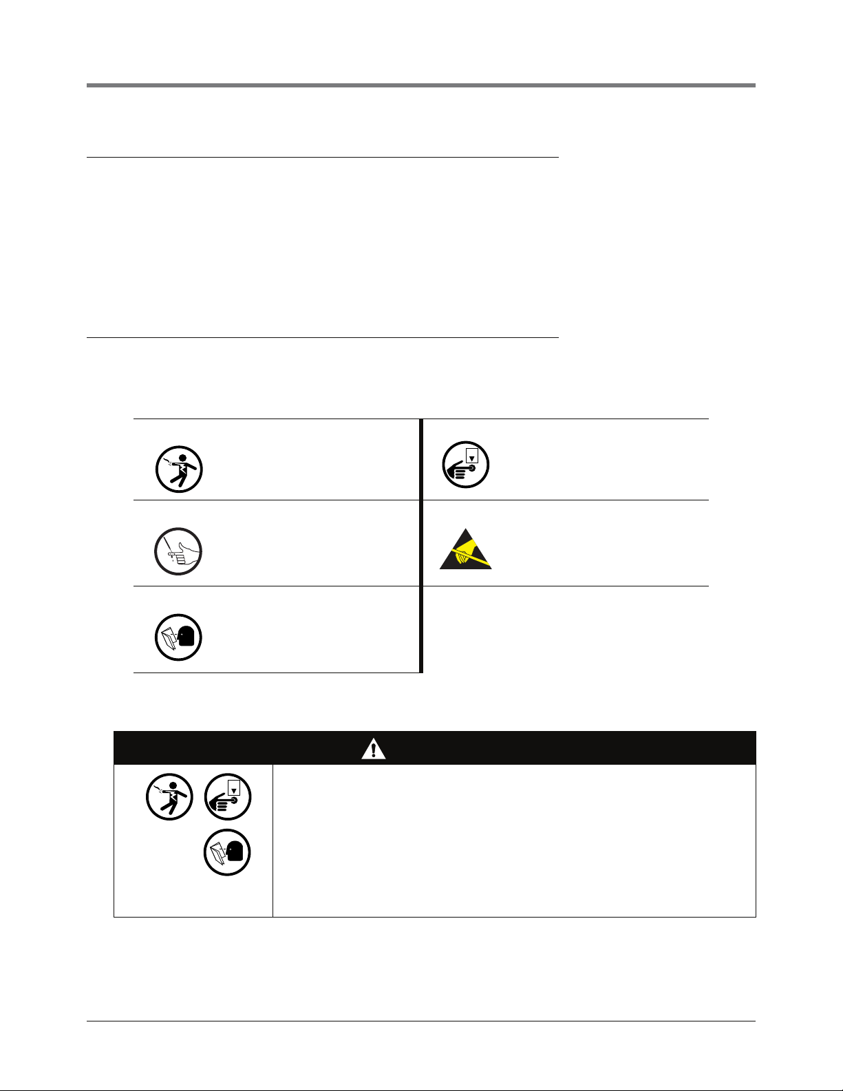
Safety Precautions
The following safety symbols may be used throughout this manual to alert you to important safety hazards and
precautions.
ELECTRICITY
High voltage exists in, and is supplied
to, the device. A potential shock hazard
exists.
INJURY
Careless or improper handling of tools
can cause bodily injury.
READ ALL RELATED MANUALS
Knowledge of all related procedures
before you begin work is important.
Read and understand all manuals thoroughly. If you do not understand a procedure, ask someone who does.
WARNING
This system operates on 115 Vac power. Serious injury or death from electrical
shock could occur if the power ON/OFF warnings in this manual are not
heeded.
1. Read and follow all instructions in this manual, including all safety
warnings.
2. Remove rings from hands, metal watch bands and bracelets, and loose
hanging neck jewelry before performing these procedures.
3. Do not modify or use service parts other than those provided by VeederRoot.
TURN POWER OFF
Live power to a device creates a
potential shock hazard. Turn Off power
to the device and associated accessories when servicing the unit.
STATIC SENSITIVE COMPON ENTS
Wear grounded anti-static wrist strap
before handling the printed circuit
board.
2
Page 6

Introduction Precautions Against Static Electricity
954-10.eps
1
2
1. USB/Ethernet module end plate.
2. V-R thumb drive plugged into USB port
Precautions Against Static Electricity
Before removing electronic components from their antistatic bags read the following static electricity precautions.
1. Before handling any components, discharge your body's static electric charge by touching a grounded
surface.
2. Do not remove parts from their antistatic bags until you are ready to install them.
3. Do not lay parts on the antistatic bags! Only the insides are antistatic.
4. When handling parts, hold them by their edges and their metal mounting brackets.
5. Avoid touching components or edge connectors that plug into slots.
6. Never slide parts over any surface.
7. Avoid plastic, vinyl, and styrofoam in your work area.
8. Wear the antistatic wrist strap included in your component replacement kit.
9. The antistatic caution icon shown to the left appears in several places in this manual to remind you to wear an
antistatic wrist strap (Part No. 576013-908) when handling static sensitive devices.
Before Turning Off Power
Before powering off the console perform a system backup:
• Insert the V-R Backup thumb drive (P/N 330020-604) in the external USB port on the USB/Ethernet card, P/N
332913-001 (see item 2 in Figure 1).
• Touch the Diagnostics button on the Home Screen and touch the Software Maintenance button to view the
Software Maintenance File Manager tab screen. Touch the Backup button to begin the backup process.
• After the ‘Backup Completed Successfully’ message displays, you can safely remove the V-R Backup thumb
drive.
Legend for numbered boxes in Figure 1
Figure 1. USB/Ethernet board - V-R thumb drive port
3
Page 7

Replacing the Display Door Assembly (P/N 330020-625)
OFF
1 2
1 2
956-1.eps
1. Remove top and bottom #8 taptite screws on right side of left
(Printer) door and swing door to left.
2. Remove top and bottom #8 taptite screws on right side of left
(Display) door and swing door to left.
1. Switch Off power to the console.
2. Open the two front doors of the console as shown in Figure 2
Legend for numbered boxes in Figure 2
3. Disconnect grounding braid from the saddle clamp on the inside of the Display door.
4. Disconnect the three cables from the Display door attached to the CPU board touchscreen connector, the
display data connector and the LED/Display connector (see Figure 3).
5. Remove the top and bottom #8 taptite screws in the Display door hinge and remove the door.
6. Get the replacement Display door and line up the holes in the two door hinges with the top and bottom holes
in the console housing and screw in the top and bottom #8 taptite screws. Tighten the two hinge screws.
7. Reconnect the grounding braid to the saddle clamp on the inside of the Display door.
Figure 2. Front doors
4
Page 8

Replacing the Display Door Assembly (P/N 330020-625) Before Turning Off Power
2
543
1
6
1. Top Display door hinge shoulder screw
2. Grounding braid
3. Touchscreen control cable
4. Display data cable
5. LED/Display cable
6. Bottom Display door hinge shoulder screw
Figure 3. Display door cables
Legend for numbered boxes in Figure 3
8. Reconnect the three cables from the Display door to their connectors on the CPU board (see Figure 3).
9. Close the Display door and insert the right-side top and bottom #8 taptite screws. Tighten the two screws.
10. Close the Printer door and insert the right-side top and bottom #8 taptite screws. Tighten the two screws.
5
Page 9

Replacing the Printer Door Assembly (P/N 330020-626)
OFF
1
2
3
4
5
1. Bottom Printer door hinge shoulder screw
2. USB cable
3. Power cable
4. Grounding braid
5. Top Printer door hinge shoulder screw
1. Switch Off power to the console.
2. Open the left front door of the console as shown in Figure 2.
3. Disconnect grounding braid from the saddle clamp on the inside of the Printer door (see Figure 4).
Figure 4. Printer door cables
Legend for numbered boxes in Figure 4
6
Page 10

Replacing the Printer Door Assembly (P/N 330020-626) Before Turning Off Power
4. Disconnect the two cables from the Printer door (see Figure 3).
5. Remove the top and bottom #8 taptite screws in the Printer door hinges and remove the door.
6. Get the replacement Printer door and line up the holes in the two door hinges with the top and bottom holes
in the console housing and screw in the top and bottom #8 taptite screws. Tighten the two hinge screws.
7. Attach the grounding braid to the saddle clamp on the inside of the Printer door (see Figure 4).
8. Connect the USB cable and the power cable to the printer (see Figure 4).
7
Page 11

Replacing the Power Supply (P/N 330020-623)
OFF
1
2
956-4.eps
1. USB cable
2. CF Card
1. Switch Off power to the console.
2. Open the left front door of the console as shown in Figure 2.
3. Disconnect the USB connector and remove the CF card from the CPU board (see Figure 5).
Legend for numbered boxes in Figure 5
Figure 5. Remove USB cable and CF card
8
Page 12

Replacing the Power Supply (P/N 330020-623) Before Turning Off Power
956-8.eps
1
2
2
1. AC Channel cover
2. #8 taptite screws (2)
4. Remove the two #8 taptite screws from the AC Channel cover and put the cover and screws aside (see
Figure 6).
Figure 6. Remove AC Channel cover
Legend for numbered boxes in Figure 6
9
Page 13

Replacing the Power Supply (P/N 330020-623) Before Turning Off Power
956-5.eps
1
3
1
1
2
1. #8 taptite screws (the middle one also secures the Power
Supply shield)
2. Power Supply shield
3. AC Input module handle
5. Remove the three #8 taptite screws in the AC Input module (item 1 in Figure 7).
6. Lift the Power Supply shield up to disengage the two retention snap pins in its right side flange and remove it
from the console (item 2 in Figure 7).
7. Grasp the AC Input module handle (see item 3 in Figure 7) and slowly pull up and away from the power
supply until the AC Input module disconnects from the power supply. Lift the AC Input module out of the
console.
Legend for numbered boxes in Figure 7
Figure 7. Removing AC Input module
10
Page 14

Replacing the Power Supply (P/N 330020-623) Before Turning Off Power
956-6.eps
1
5
WARNING!
Shock hazard. Do not
touch underside of
board beneath these
five capacitors.
4
3
2
1. #6 taptite screws
2. J3 - Low voltage relay control connector
3. J2 - AC Input module power connector
4. Two board retention pins.
5. Capacitors
WARNING! These caps can hold a high charge,
do not touch underside of board where these
caps are soldered to board.
8. Remove the three #6 taptite screws (item 1 in Figure 8) that secure the Power Supply board to the console
housing.
9. Place fingers under the Power Supply board (at locations indicated by two arrows in Figure 8) and lift the
board up until it is free of the two retention pins (item 3 in Figure 8).
10. Disconnect the printer power cable from the Power Supply board.
11. Lift the board out of the console by its edges since there is still undischarged high voltage in the big
capacitors.
Legend for numbered boxes in Figure 8
Figure 8. Removing Power Supply
11
Page 15

Replacing the Power Supply (P/N 330020-623) Before Turning Off Power
956-7.eps
2
1
1. This hole lines up over the middle hole in AC Input Module
bracket
2. The two holes in the right side flange of the Power Supply
shield line up over the retention pins (indicated by two arrows)
in the back of the console housing.
12. Get the new Power Supply board and lower into console.
13. Attach the printer power supply cable to its connector (J1) on the upper right corner of the replacement Power
Supply board.
14. Lineup the two holes in the Power Supply board (see item 4 in Figure 8) with the two retention pins in the
back of the console housing and push the board down until the pins snap into position.
15. Install the three #6 taptite screws (item 1 in Figure 8) and tighten them.
16. Get the AC Input module. Notice that there are two male connectors on the bottom of the AC Input module
board that plug into two female connectors on the Power Supply board. With the handle (item 3 of Figure 7)
of the AC Input module against the left side of the console housing, line up the two AC Input module bottom
connectors over the two female connectors (items 2 and 3 in Figure 8) on the Power Supply board and push
down on the AC Input module until the connectors are firmly seated.
17. Place the Power Supply shield (item 2 in Figure 7) over the Power Supply board and lower it down onto its
two retention pins (see item 2 in Figure 9) and snap it into place.
18. Install the three #8 taptite screws in the AC Input module (see item 1 in Figure 7).
19. Replace the AC Channel cover and install the two #8 taptite screws (see Figure 6).
Figure 9. Replacing Power Supply shield over Power Supply board
Legend for numbered boxes in Figure 9
12
Page 16

For technical support, sales or
other assistance, please visit:
www.veeder.com
 Loading...