

Page 1

Manual No: 577014-110 ● Revision: B
Operator’s Manual
TLS-450PLUS / TLS4
Page 2

Notice
Veeder-Root makes no warranty of any kind with regard to this publication, including but not
limited to, the implied warranties of merchantability and fitness for a particular purpose.
Veeder-Root shall not be liable for errors contained herein or for incidental or consequential
damages in connection with the furnishing, performance, or use of this publication.
The information contained in this publication may be subject to change without notice.
This publication contains proprietary information which is protected by copyright. All rights
reserved. No part of this publication may be photocopied, reproduced, or translated to another
language without the prior written consent of Veeder-Root.
©Veeder-Root 2016. All rights reserved.
Page 3

Introduction
Contractor Certification Requirements ..............................................................................1
Related Documents ..........................................................................................................1
Console Touch Screen Overview
Console Home Screen ......................................................................................................2
Front Panel Status Lights .........................................................................................2
Example Touch Screen Status Bar Notifications .....................................................2
Touch Screen Icon Descriptions .......................................................................................3
Entering Changes On A Touch Screen ............................................................................4
Console Comm Ports ........................................................................................................4
TLS4 Comm Ports - Menu>Setup>Communication .................................................4
TLS-450PLUS Comm Ports - Menu>Setup>Communication...................................5
Alarm Limit Settings - Menu>Setup>Tank>Limits .............................................................5
Security Login ...................................................................................................................6
Using On-Board Help - Actions>Help ...............................................................................6
On-board Help Topics of Interest - Actions>Help.....................................................6
System Maintenance Screen Examples ...........................................................................7
Backup System Data - Menu>Software Maintenance>DB Backup..........................7
To View The Console’s Software Version - Menu>Overview>About .......................7
To Download Console Software - Menu>Software Maintenance>Download ...........7
Table of Contents
Initial Setup Of The Console Using Workflow Wizard
Initial Screen - Menu>Setup>Workflow Wizard>Setup Workflow .....................................9
Setup>Display>Language/Units ...............................................................................9
Setup>Date and Time ..............................................................................................9
Setup>Display>Date/Time Format .........................................................................10
Setup>Display>Number Format .............................................................................10
Setup>Headers ......................................................................................................11
Setup>System>Alarm Filtering...............................................................................11
Setup>Communication>System Hostname............................................................12
Setup>Communication>Ethernet Port....................................................................13
Setup>Communication>Internal Modem................................................................14
Setup>Communication>CDIM Port ........................................................................15
Setup>Communication>TDIM Port.........................................................................15
Setup>Communication>IFSF .................................................................................16
Setup>Communication>Serial Port ........................................................................17
Setup>Communication>SMTP Relay.....................................................................18
Setup>Devices ......................................................................................................19
Setup>BIR>General ...............................................................................................24
Setup>BIR>Threshold Alarm..................................................................................25
Setup>Tank>General .............................................................................................26
Setup>Tank>Limits.................................................................................................28
Setup>Tank>Limits - Concluded ............................................................................29
Setup>Tank>Environmental Test ..........................................................................30
Setup>Tank>Profile................................................................................................32
Setup>Tank Chart>Charts......................................................................................33
Setup>Tank>HRM Limits (International Option).....................................................34
Setup>Tank>Siphon Sets.......................................................................................35
Setup>Tank>All Tanks ...........................................................................................36
Setup>Products>Labels .........................................................................................37
Setup>Product>Product Mapping ..........................................................................37
Setup>Tank Chart>AccuChart ...............................................................................38
Setup>Pumps and Lines>Pumps...........................................................................40
Setup>Pumps and Lines>Line ...............................................................................41
iii
Page 4

Setup>Pumps and Lines>PLLD .............................................................................42
Setup>Pumps and Lines>All Lines.........................................................................44
Setup>Pumps and Lines>All PLLD ........................................................................45
Setup>Inventory>Report Times..............................................................................46
Setup>Inventory>Shifts ..........................................................................................46
Setup>Delivery .......................................................................................................47
Setup>Automatic Events>Address Book................................................................48
Setup>Automatic Events>AutoXmit .......................................................................49
Setup>Automatic Events>Autoconnect Tasks .......................................................50
Setup>Automatic Events>Device Tasks ................................................................51
Setup>Automatic Events>Print Tasks....................................................................52
Setup>Automatic Events>All Tasks .......................................................................53
System Administration>Roles Admin .....................................................................54
System Administration>Users Admin .....................................................................56
Setup>System>Security.........................................................................................57
Software Maintenance
Activate/Revert Screen (Menu>Software Maintenance>Activate/Revert) ......................58
Notes on Reverting to a Previous Software Version ..............................................59
DB Backup (Menu>Software Maintenance>DB Backup) ................................................60
Example Database Backup Procedure...................................................................60
DB Restore (Menu>Software Maintenance>DB Restore) ..............................................61
Download (Menu>Software Maintenance>Download) ....................................................62
Example Software Download Procedure................................................................62
System Snapshot (Menu>Software Maintenance>System Snapshot) ...........................63
Example System Snapshot Procedure...................................................................64
Upgrade Features (Menu>Software Maintenance>Upgrade Features) ..........................64
Table of Contents
Figures
Tables
Figure 1. TLS4 Comm Ports ..................................................................................4
Figure 2. TLS-450PLUS Comm Ports ....................................................................5
Figure 3. Initial Setup Home Screen ......................................................................8
Figure 4. Accessing Workflow Wizard Setup .........................................................8
Figure 5. Software Maintenance Screen ..............................................................58
Table 1. Activate/Revert Screen Field Descriptions ..............................................59
Table 2. DB Backup Screen Field Descriptions ....................................................60
Table 3. DB Restore Screen Field Descriptions ....................................................61
Table 4. Download Screen Field Descriptions ......................................................62
Table 5. System Snapshot Screen Field Descriptions ..........................................63
Table 6. Upgrade Features Screen Field Descriptions .........................................64
iv
Page 5

Introduction
This manual contains instructions for using the Workflow Wizard Setup Application in the TLS450PLUS and TLS4/8601
Series consoles. Workflow Wizard guides the user through the Veeder-Root recommended setup screens during the
console’s initial commissioning.
This manual assumes all devices are connected the console and that a site diagram of all probes, sensors and tanks is at
hand to assist in determining the correct console addresses for these devices. The procedures herein are intended to be
followed using the console’s touch screen. Other setup interface methods vary in feature and accessibility options.
Some of the screens are only visible if the applicable features/devices are installed in your console. Skip over programming
instructions for any features/devices that are not installed in your console.
Contractor Certification Requirements
Veeder-Root requires the following minimum training certifications for contractors who will install and setup the equipment
discussed in this manual:
Installer (Level 1) Certification: Contractors holding valid Installer Certification are approved to perform wiring and
conduit routing; equipment mounting; probe, sensor and carbon canister vapor polisher installation; wireless equipment
installation; tank and line preparation; and line leak detector installation.
ATG Technician (Level 2/3 or 4) Certification: Contractors holding valid ATG Technician Certifications are approved to
perform installation checkout, startup, programming and operations training, system tests, troubleshooting and servicing for
all Veeder-Root Series Tank Monitoring Systems, including Line Leak Detection. In addition, Contractors with the following
sub-certification designations are approved to perform installation checkout, startup, programming, system tests,
troubleshooting, service techniques and operations training on the designated system.
Related Documents
577014-073 TLS450PLUS Site Prep Manual
577014-075 TLS-450PLUS Troubleshooting Guide
577014-022 TLS4 Site Prep Manual
577014-058 TLS4 Troubleshooting Manual
577013-465 Electronic Line Leak Detectors Application Guide
577013-770 Media-Isolated Mag Plus Probe LPG-ISO Kit Installation Guide
577013-773 Media-Isolated Mag Plus Probe Chem-ISO Kit Installation Guide
577014-056 Mag-FLEX Probe Low Level Water Float Kit Installation Guide
1
Page 6
Console Touch Screen Overview
T 1: DELIVERY NEEDED 01/20/2016 06:01 PM
Tank Overview
TANK 1: reg
Fuel Volume 3655
Fuel Height 38.6
Ullage 100% 6345
Temperature 61.9
Water Height 3.0
1 Warning(s)
0 Alarms(s)
Print (0)
Home
Favorites
Menu
Actions
Overview
!
See Example
Status Bar
Types Below
Bread Crumbs
0
M
)
0
)
P
)
p
le
Bar
Date & Time
Print Button
SYSTEM STATUS
0 Warning(s)
0 Alarms(s)
SAVING
0 Warning(s)
0 Alarms(s)
T2: DELIVERY NEEDED
1 Warning(s)
0 Alarms(s)
L 10: FUEL ALARM
0 Warning(s)
1 Alarms(s)
Power On to console and no warnings or
alarms from system.
System tasks message bar.
Something needs to be reviewed and/or assessed. In
this state, touching the status/warning bar brings you
to the Reports > Alarms > Active screen so you can
see the cause of the warning. While in that screen,
touching the status/warning bar again acknowledges
the warning and shuts off the beeper.
Something needs to be acted upon immediately. In
this state, touching the status/warning bar brings you
to the Reports > Alarms > Active screen so you can
see the cause of the alarm. While in that screen,
touching the status/warning bar again acknowledges
the alarm and shuts off the beeper.
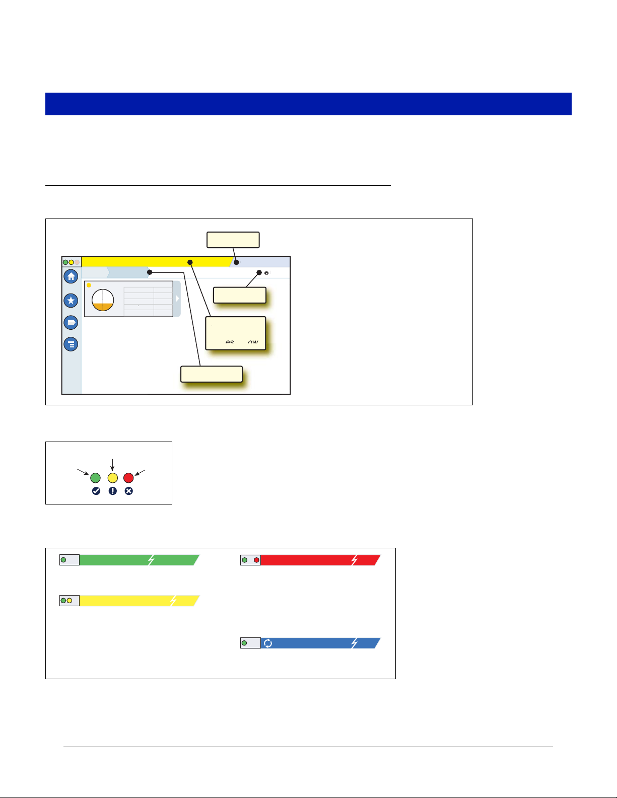
The following section console features, touch screen layout and how to access and navigate the setup procedure using the
touch screen controls.
Console Home Screen
An example Tank Overview Screen (Default Home Screen) is shown below which has 2 Tanks Monitored and 1 active
Warning
1 Warning(s
Alarms(s
1/20/2016 06:01 P
rint (0
ee Exam
Front Panel Status Lights
Warning
Normal
Alarm
Example Touch Screen Status Bar Notifications
2
Page 7
Console Touch Screen Overview Example Touch Screen Status Bar Notifications
1
Touch Screen Icon Descriptions
Home Screen Icon - Touch to navigate to the home screen. Default is the Tank Overview screen (Home screen shown
above).
Favorites Screen Icon - Touch to setup/access your favorite screens and designate which screen will be the home
(default) screen.
Touch to add the current screen to your Favorites list. You can have up to six Favorites screens. If you want to delete a
screen from your Favorites list, touch next to that screen.
Touch to set the current screen as the home screen.
Menu Icon - Touch to access System Setup Menus, Reports, Diagnostics and other screens (Administrator assigned
access). For initial setup of the console, touch Menu>Setup>Workflow Wizard which steps you through the console setup
screens in the proper sequence. See Workflow Wizard setup
Actions Icon - Touch to access Help. Touch the Help icon to open On-Board Help. Also, if the Shifts feature is set up,
touching the Actions icon will display the Close Shift icon which can be touched to close a shift.
Unrelated to the choices above, when entering data in any screen, a Red Circle may appear on the Actions icon to indicate that additional tasks/menu choices for that screen.
Screen Dependent Icons - The number in the circle under the Actions icon indicates the device you are viewing or
setting up. Touching the circled number displays all of the similar devices in a row along the bottom of the screen (other
tanks, ports, probes, etc.) that you have set up. Touching the circled number again hides the device icon row. A highlighted
icon indicates the device you are viewing or setting up. Some of the device icons you may see depending on system
features installed in your console are shown below:
1
Tank Ethernet
Port
Device
Product Sensor Printer Siphon
Probe External
Input
Set
Relay
Serial
Port
3
Page 8
Console Touch Screen Overview TLS4 Comm Ports - Menu>Setup>Communication
4
n
e
a
printers
g
h
r
t
w
o
e
c
nge to a
touch the ke
USB port (1) upper
USB port (2) lower
SWITCH ETH 2 & 3 - shown
in Setup menu as
Ethernet Port 2 (Optional)
Factory Installed,
Optional Module
Area
VR Bus port Ethernet port (1) RS-232 or RS-485 DB9 ports
EXPANSION
SERIAL 1
SERIAL 2
ETH 2
ETH 3
USB 1
USB 2
ETH 1
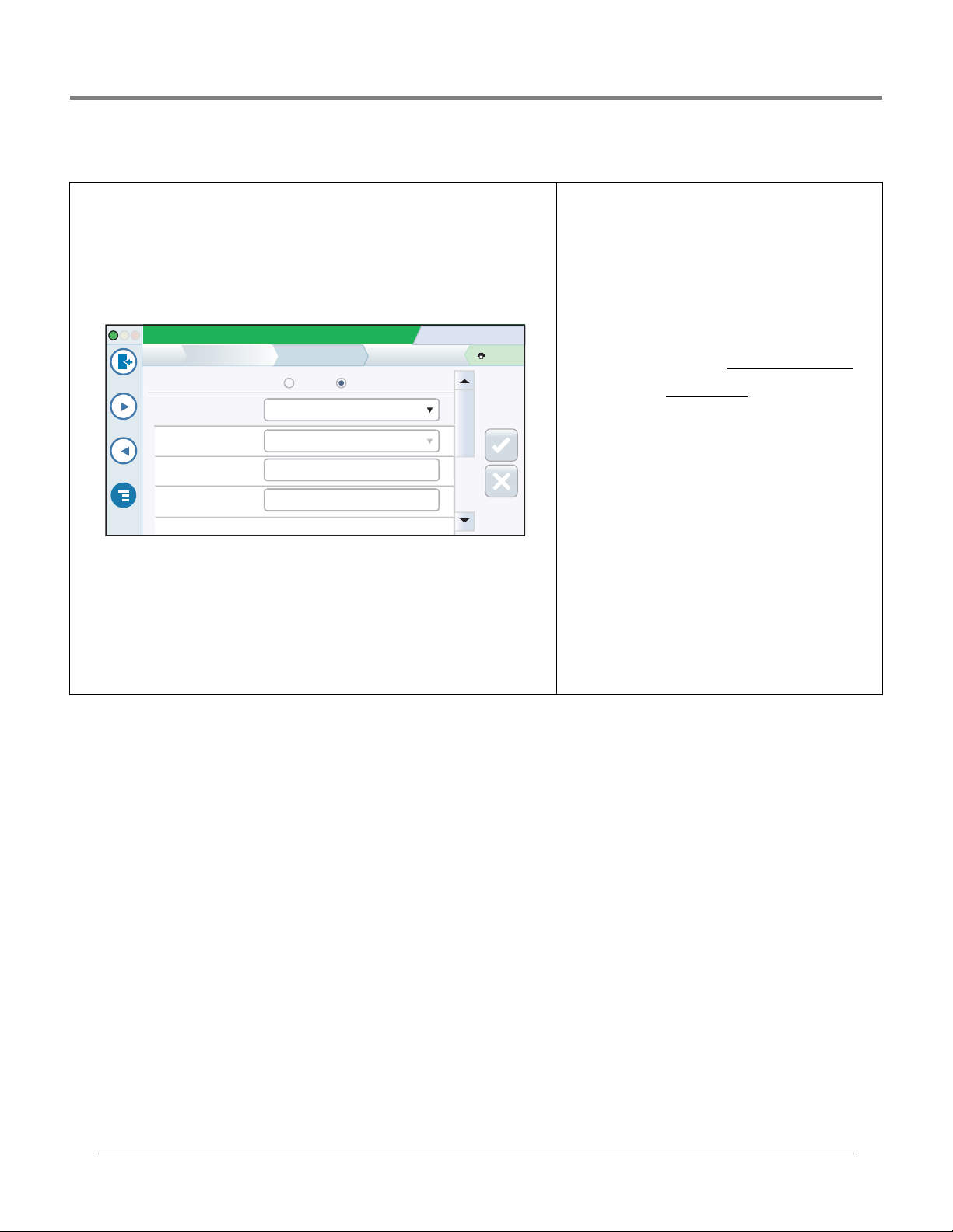
Entering Changes On A Touch Screen
The screen example below describes entering data into the screen’s field windows.
Touch down arrow in a menu
breadcrumb to view all additional setup
s
creens, select any in list to jump
White (empty) radio button indicates item is not selected.
Touch radio button to select Disabled and deselect Enabled.
to that screen
System Status
Printers
Home
Favorites
Menu
Actions
1
Printer
Setup
Configured
Driver Selection
Setup
Printer
Is Default
Label
URI
1
Selected device. Touch to select
additional devices to be programmed,
in this case additional printers.
0 Warning(s)
07/20/2013 09:01 AM
0 Alarms(s)
Enabled Disabled
APS_CP324HRS_640_USB_1
Yes No
TLSIntegralPrinter
dev/bus/usb?type=usb+vid=6868+pld=4
Automatic Manual
4
Touching in a white field displays
a pop-up keyboard/keypad to enter
or modify an entry.
Print (0)
*
A grayed-in field cannot be changed.
In this example, if there two or more
printers, the field would be white and
touching the down arrow would display
the additional printers.
After making any change to a screen
Aft
entry, touch the key to accept the
ent
change(s) or touch the key to
ch
cancel the change(s).
ca
If page scroll is visible, touch the up/down
makin
touc
(s) o
l the c
scroll
i
.
ange(s).
s visible, touch th
creen
pt the
to
up/d
arrows or slide bar with finger to scroll up
or down to view additional entry fields.
An asterisk (*) next to a field indicates you
changed
an entry for that field before you have accepted or
saved the change in a dialog window.
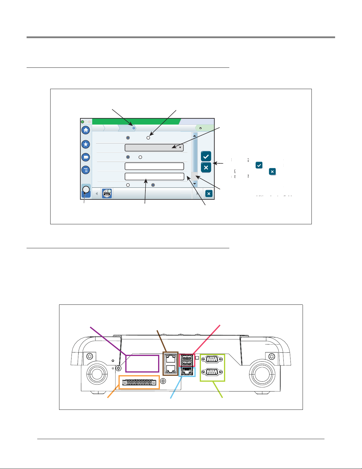
Console Comm Ports
When setting up comm ports, you should verify the connections to the console’s comm ports prior to entering their setup
parameters.
TLS4 Comm Ports - Menu>Setup>Communication
Your console’s Comm Port configuration will depend on features ordered. Note: Ethernet ports 2 and 3 are programmed as
the same ethernet device.
Figure 1. TLS4 Comm Ports
4
Page 9
Console Touch Screen Overview TLS-450PLUS Comm Ports - Menu>Setup>Communication
USB ports: (1) upper, (2) lower
Future expansion port
*Both ports of ethernet 2
are programmed the same.
Ethernet port:
(1) upper
Ethernet port 2:
middle and lower switched*
Front of
Console
Port 2
Bottom of
console
Port 1
Selectable Comm
Device slots
Fixed Comm
Device slots
12345
High Water Warning
High Water Alarm
Low Product
Delivery Overfill
Delivery Overfill
High Product
Max (Label) Volume
Full Volume (Ref.)
Full Volume (Ref.)
Pump Inlet (Ref.)
Delivery Limit
Delivery Limit
SAFE WORKING CAPACITY
Maximum Product Alarm Level
("Label" Volume)
High Product Alarm Level
Fuel Draw
Off Level
(Ref.)
High Water Warning Level
Low Product Alarm Level
High Water Alarm Level
Interstitial Sensor/Sump Sensor
Typical European TankTypical North American Tank
TLS-450PLUS Comm Ports - Menu>Setup>Communication
Your console’s available Comm Port configuration will depend on features ordered.
Figure 2. TLS-450PLUS Comm Ports
Alarm Limit Settings - Menu>Setup>Tank>Limits
The diagrams below show the relative position of tank alarm (Limit) settings. See “Setup>Tank>Limits” on page 27 for
more information about tank alarm limits.
5
Page 10

Console Touch Screen Overview On-board Help Topics of Interest - Actions>Help
Username:
Password:
Language:
Sign In Cancel
Default
Logout
Security Login
If the console Security Feature is Enabled - Touch the Login button to open the login screen so you can login as a
Login
user:
Once the screen displays, log in to the system
with your Username and Password. NOTE: If you
do not log in, you are only permitted to view
system status screens and to print out end-user
reports.
Touch the Logout button to log out of
the console. NOTE: If the console is inactive for
15 minutes, the console will automatically log
you out. You will need to log back in to access
your user account.
Using On-Board Help - Actions>Help
Note: On-board help covers all console features, some of which may not be on visible/applicable if they were not ordered
with your console.
To access On-Board Help touch the Actions icon then touch the Help icon .
Upon entering Help, the topic associated with the currently displayed screen will be visible. Repeatedly touch the side
scroll bar up/down arrows to scroll through a topic. You can also drag and pan through a topic. Touch the ‘X’ in the right
corner of the Help screen title bar to return to the TLS4/TLS-450PLUS screen you were viewing.
•To show or hide the help Table of Contents (TOC) pane on left side of screen - Quickly tap the text (Show TOC or Hide
TOC) twice with your finger.
•To expand ( ) or close ( ) a book - Touch the icon of the book once with your finger.
•To go to a topic ( ) within a book - Quickly tap the book topic twice with your finger.
•Touch the side TOC scroll bar, and either move your finger up (to scroll down) or move your finger down (to scroll up).
•Repeatedly touch the side TOC scroll bar upper arrow to scroll up, or repeatedly touch the side scroll bar down arrow to
scroll down.
On-board Help Topics of Interest - Actions>Help
• Understanding ATG -This help section explains the fundamentals of automatic tank gauges (ATG) as implemented by
Veeder-Root.
• Configuration and Maintenance - This help book discusses Comm Ports, Initial Console Setup Sequence, and Periodic
Maintenance recommendations.
• Welcome (Help Intro) , Screen Icons, On-Screen Keyboards, and Touchscreen navigation are essential help topics which
you can view in the On-Board Help’s Table of Contents.
• Reference Tables - This help section contains topics that cover a wide variety of useful information replaceable fuses, VR acronyms, system device identifiers, tank tilt calculation information, DIM data, etc.
6
Page 11

Console Touch Screen Overview Backup System Data - Menu>Software Maintenance>DB Backup
System Status
07/20/2013 09:10 AM
0 Warning(s)
0 Alarms(s)
Print (0)
Home
Favorites
Menu
Actions
Software Maintenance
Current Version
Available Version
Current Operations
Backup Destination
Version
1.gB 230.4
Not available
Select a source to retrieve versions available
IDLE
DB Backup
Select destination device
System Status
07/20/2013 09:18 AM
0 Warning(s)
0 Alarms(s)
Print (0)
Home
Favorites
Menu
Actions
Overview
Console Series # 8601
Software Part # 342004-001.gB230.4r71119
ATG Functionality
Email Notification
Custom On-Board Help
Custom Alarms
Web Enabled
Extended Storage L2
Created Jul 29 2013 17:43:52
About
Hardware Description
Installed Features
Serial #
CPU 11260090
iButton 000D016283f20b
UNIV SENS I/O MODULE (B1.S1) 000D016283f20b
Max Allowed Ports 9
System Status
07/20/2013 09:10 AM
0 Warning(s)
0 Alarms(s)
Print (0)
Home
Favorites
Menu
Actions
Software Maintenance
Current Version
Available Version
Current Operations
Backup Destination
Version
1.gB 230.4
Not available
Select a source to retrieve versions available
IDLE
Download
Select Source
System Maintenance Screen Examples
Backup System Data - Menu>Software Maintenance>DB Backup
Insert your Fat 32 formatted thumb drive (mini-
mum 4 GB) in a USB port and touch the down
arrow in the Backup Destination field to select
the thumb drive, then follow the on-screen
instructions to backup console data.
You should perform a DB Backup weekly.
To View The Console’s Software Version - Menu>Overview>About
This screen provides important information about
your console's software version and installed
features. If you should be experiencing problems
with the console, please have the information on
this screen available with you before contacting
us.
The Veeder-Root Technical Support number is
(800) 323-1799.
To Download Console Software - Menu>Software Maintenance>Download
Insert your valid V-R Code thumb drive in a USB
port and touch the down arrow in the Backup
Destination field to select the coded thumb drive,
then follow the on-screen instructions to begin
the download. Once the download process has
completed, you must activate the software (see
“Activate/Revert Screen (Menu>Software
Maintenance>Activate/Revert)” on page 58).
7
Page 12

Initial Setup Of The Console Using Workflow Wizard
After the console has been installed and connected to the power panel and to all site monitored devices, apply power to
the console and let it boot up and display the Home Screen (see below).
Figure 3. Initial Setup Home Screen
Access Workflow Wizard Setup by touching Menu>Setup>Workflow Wizard>Setup Workflow:
Figure 4. Accessing Workflow Wizard Setup
8
Page 13
Initial Setup Of The Console Using Workflow Wizard Setup>Display>Language/Units
Touch the Exit icon to quit
Workflow Wizard and return
to the Home screen
Touch to step back to
previous screen
Touch to step forward to
next screen
Touch the and icons
to access online help for the
current screen
Initial Screen - Menu>Setup>Workflow Wizard>Setup Workflow
The initial setup screen in the Workflow Wizard app is shown below. Note that the Workflow Wizard steps through the
setup screens in a V-R recommended sequence for initial setup of the console. This manual assumes all devices are
connected and recommends you are accessing WW setup from the console GUI. Other setup interface methods vary in
feature and accessibility options.
Navigating Workflow Wizard is described in the figure below. When you exit the Workflow Wizard app, or it times out,
reentering the app always returns you to the initial screen. To return to the screen you were working on after exiting the app,
touch the Next button repeatedly until the desired screen is displayed.
Once the console is setup and functioning and a screen needs modification, the user would likely use the standard quicker
path (from the home screen) to the desired screen, e.g., Menu>Setup>etc>etc..
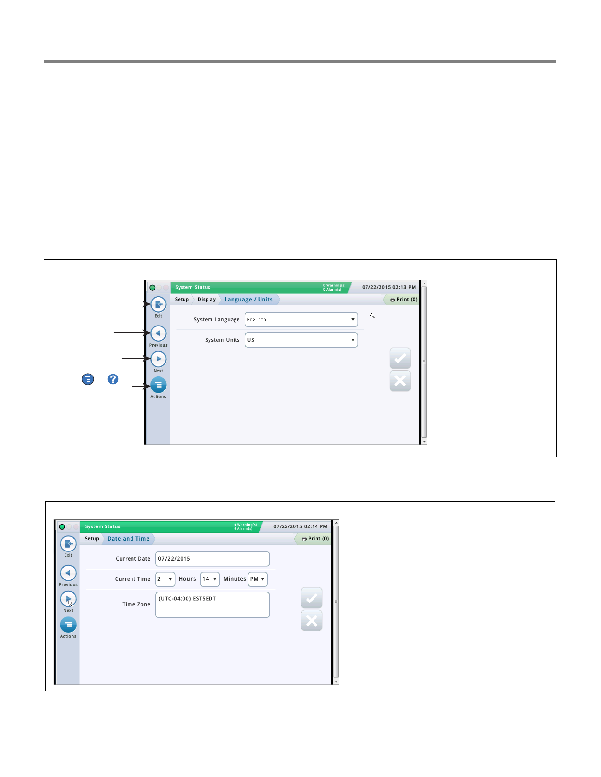
Setup>Display>Language/Units
System Language
Touch to select the system lan-
guage used for all displays and
reports.
System Units
Touch to select U.S., Metric or
Imperial units to be used in all
displays and calculations.
Setup>Date and Time
This screen lets you enter the current date and time for the console.
Current Date
Touch to enter current date.
Current Time
Touch each field to enter time.
Note: the default time format is 12 hour AM/PM (hh:mm AP).
If 24 hour time is desired, enter the correct time on this
screen then select hh:mm in the Time Format field in the
next Workflow Wizard screen.
Note: Switching to and from Daylight Savings Time is automatic based upon your time zone entry below
.
Time Zone
Touch and scroll to select local time zone.
9
Page 14
Initial Setup Of The Console Using Workflow Wizard Setup>Display>Date/Time Format
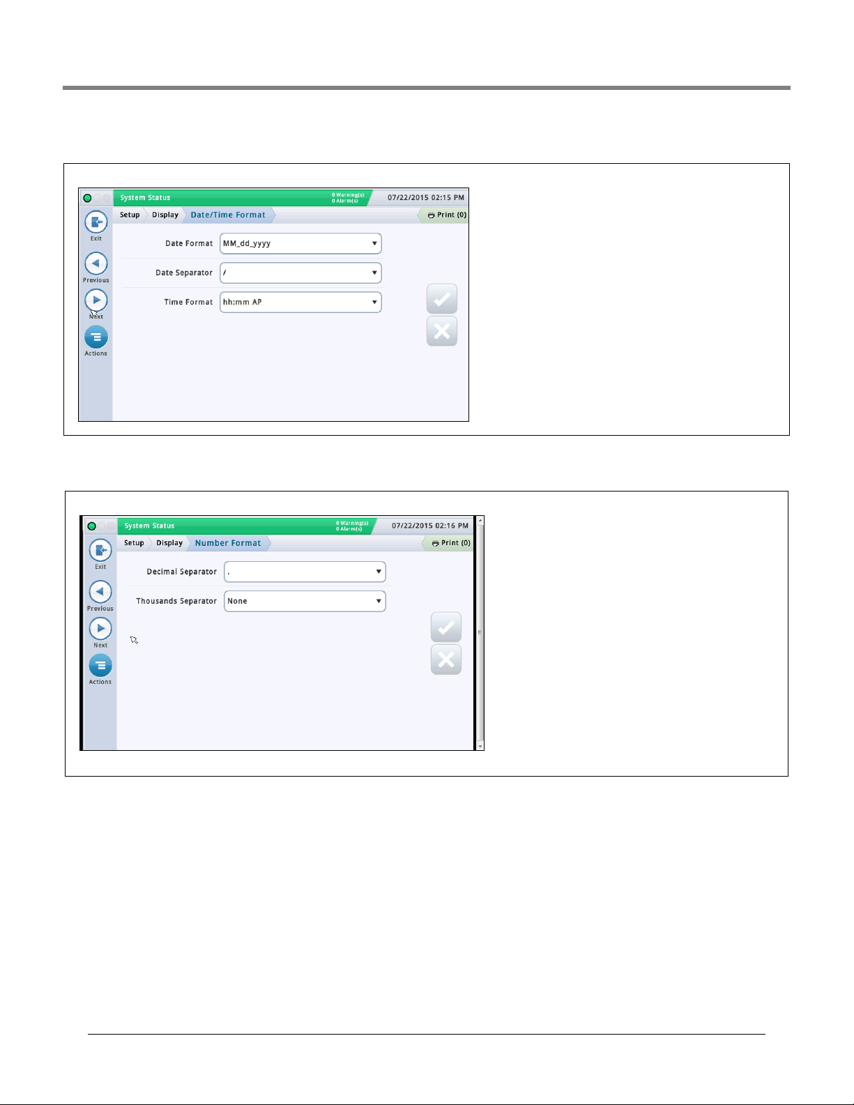
Setup>Display>Date/Time Format
This screen lets you select the date and time format used in all screens and reports.
Date Format
Touch to enter desired date format.
Date Separator
Touch to enter desired date separator.
Time Format
Touch to select 24 hr time (hh:mm) or 12
hour AM/PM time (hh:mm AP).
Setup>Display>Number Format
This screen lets you select the numerical separators used in all screens and reports.
Decimal Separator
Touch to enter desired decimal separator.
Thousands Separator
Touch to enter desired thousands separator.
10
Page 15
Initial Setup Of The Console Using Workflow Wizard Setup>Headers
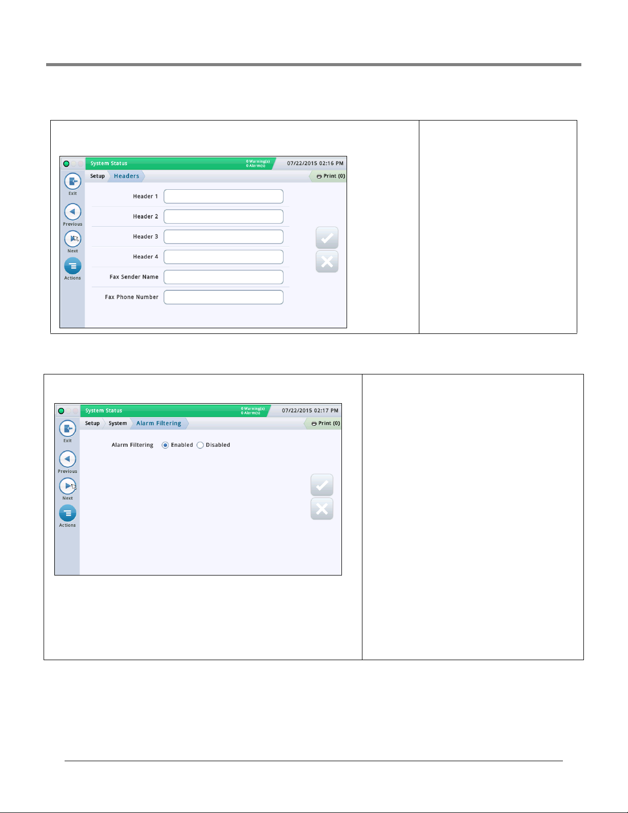
Setup>Headers
This screen lets you enter information to identify your site location, address, phone number, etc. This infor-
mation appears on the top of most inventory and BIR reports. This screen also lets you enter a fax sender
name and fax number when sending faxes.
Header 1 - 4
Touch to enter desired Site Name (1),
Street (2), City and State (3) and Phone (4) up to 20 characters each header.
Fax Sender Name
Touch to enter data printed at top of transmitted faxes from console - up to 30 alphanumeric characters.
Fax Phone Number
Touch to enter phone number to which the
console will dial to send faxes - up to 40
digits.
Setup>System>Alarm Filtering
This screen lets you enable/disable Alarm Filtering. Alarm Filtering reduces the total num-
ber of alarms without compromising the reporting of critical alarms.
Alarm Filtering
When this feature is enabled, the console manipulates a combination of the detection time
(the time before an alarm sounds) and the clear time (the time before an alarm is reset) for
certain alarms that often go in and out of an alarm state in a short period of time. In addition, some alarm reports during the clear time are consolidated, reducing their number
without eliminating the alarm reports.
Mag Sensors
The following Mag Sensor alarms will be filtered:
• Mag sensor fault, install and communication alarms - NOTE:
Mag Sensor alarms are reset if the Mag Sensor is replaced
or deconfigured and then reconfigured.
Analog Sensors
The following Liquid, Vapor, Groundwater, Type A (2-wire) and
Type B (3-wire) alarms will be filtered:
• Open, Short, Water, Water Out, Liquid Warning, Low Liquid,
High Liquid and Fuel - NOTE: Liquid Warning, High Liquid,
Low Liquid and Fuel alarms are posted immediately even
when filtered.
DIMs (Dispenser Interface Modules)
The following DIM alarm will be filtered:
•Communication Alarm - NOTE: If there is more than one DIM
card in the console, each card is filtered independently. DIM
alarm filtering takes into account the possibility of lost POS
sales data by monitoring dispensing during the clear time,
but the possibility exists that the filter may not identify all
cases when POS sales data may be lost. Unfiltered DIM
Communication Alarm reports are available by contacting
Veeder-Root Technical Support.
Probes
The following Probe alarm will be filtered:
•Probe Out
11
Page 16
Initial Setup Of The Console Using Workflow Wizard Setup>Communication>System Hostname
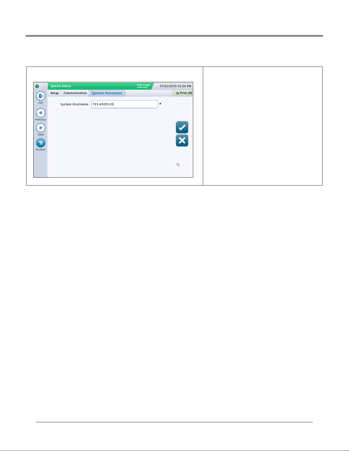
Setup>Communication>System Hostname
This screen lets you specify and change the host name of this console (i.e., what the console
is called on the customer's network, such as "MyTLSConsole").
System Hostname
Touch to select the host name of the console as it appears on
the customer’s network, in this example TLS-450PLUS.The
default host name can be changed to accommodate the customer’s network needs.
A blank host name is not allowed. The host name may contain only ASCII letters ‘a’ through ‘z’ (case-insensitive), digits ‘0’ through ‘9’ and the hyphen ‘-’ with no spaces or other
characters allowed.
(Note: the console converts any uppercase letters in the host
name to lower case when they are saved.)
12
Page 17

Initial Setup Of The Console Using Workflow Wizard Setup>Communication>Ethernet Port
Setup>Communication>Ethernet Port
MAC Address [Read-only field] Physical address of the Ether-
net board and is automatically updated by the system (for example,
01:23:45:67:89:ab).
Serial Command Port
Address of serial port used for communications in the console
(default port is 10001). If the customer is using port 10001 already
for another device, you can select another port.
NOTES:
• Do not use ports 20001, 22, 80, or 443. These are used for other
communication purposes within the console.
• If each Ethernet comm device on the console has a different IP
address they can be setup with the same serial command port. Otherwise, when setting up two or more Ethernet devices with the
same IP address on the same serial command serial port, communications may be compromised and no warning messages will be provided.
• When the serial command port is disabled on the “Setup>System>Security” screen, the Serial Command Port field on this
This screen lets you configure the ethernet port(s) on the console which is used for
remote connectivity to a POS, remote printer, etc.. NOTE: Changes made in this screen
may take 10 - 15 seconds before they take effect and then display on the screen. The
fastest way to see changes is to accept the changes, go to the Home screen, then back
to this screen.
The default port selection is Ethernet Port 1. If more than one Ethernet Port is installed
(as in the example above), complete all of the entries for port 1, then select the next
Ethernet port from the icon list on the bottom of the screen that you want to configure
and repeat the complete field entry process for port 2.
IP Address Type
Dynamic - An Ethernet comm device can have a different IP address every time it connects to the network. This address is usually administered by a network service such as
DHCP (Dynamic Host Configuration Protocol).
Static [Default] - An Ethernet comm device will have a permanent IP address every
time it connects to the network. This is entered once on the console.
IP Address
[Field only available if IP Address Type is set to Static]
Enter an IP address that was assigned by the customer's IT department (the default
setting of 192.168.11.100 won't work).
IP Subnet Mask
[Field only available if IP Address Type is set to Static]
Default is 255.255.255.0 and is typical of console configurations. Do not change unless
assigned something different by the customer's IT department.
IP Gateway Address
[Field only available if IP Address Type is set to Static]
Enter a Gateway address that was assigned by the customer's IT department (the
default setting of 192.168.11.100 won't work).
IP Default Gateway
When set to Enabled, makes this Ethernet port the default pathway for outbound communications, such as email.
Primary DNS
[Field only available if ‘IP Address Type’ is set to Static]
Enter a Primary DNS address that was assigned by the customer's IT department.
Secondary DNS
[Field only available if ‘IP Address Type’ is set to Static]
Enter a Secondary DNS address that was assigned by the customer's IT department.
screen is not available.
SSH Port
A secure port that is required by the console to ensure protection on
the communication side of the device. The default port is 22 and
should not be changed.
NOTE: Any changes to this field will affect the same field for the
other Ethernet comm device (if one exists).
HTTPS port
A secure port used by the browser to ensure security on the
browser’s side of the device. The default port is 443 and should not
be changed.
NOTE: Any changes to this field will only affect the specific Ethernet
port being programmed.
Changes to the HTTPS port will affect web enable access.
Serial Command Security
Enables or disables the requirement of entering a security code to
make changes to the Ethernet comm ports.
Security Code
[Field available if Serial Command Security field is enabled]
Enter a security code (6 alphanumeric characters) that will be
required to make any change to the Ethernet comm port(s).
ETX Characters Display
[Field enabled only if RSR 232 End of Message field is enabled]
End-Of-Text (ETX) character. ETX is programmable if enabled via the
S53100f command. If it is disabled, the ETX is a fixed Control-C character (ASCII 03).
ETX Characters Computer
[Field enabled only if RSR 232 End of Message field is enabled]
End-Of-Text (ETX) character. ETX is programmable if enabled via the
S53100f command. If it is disabled, the ETX is a fixed Control-C character (ASCII 03).
13
Page 18
Initial Setup Of The Console Using Workflow Wizard Setup>Communication>Internal Modem
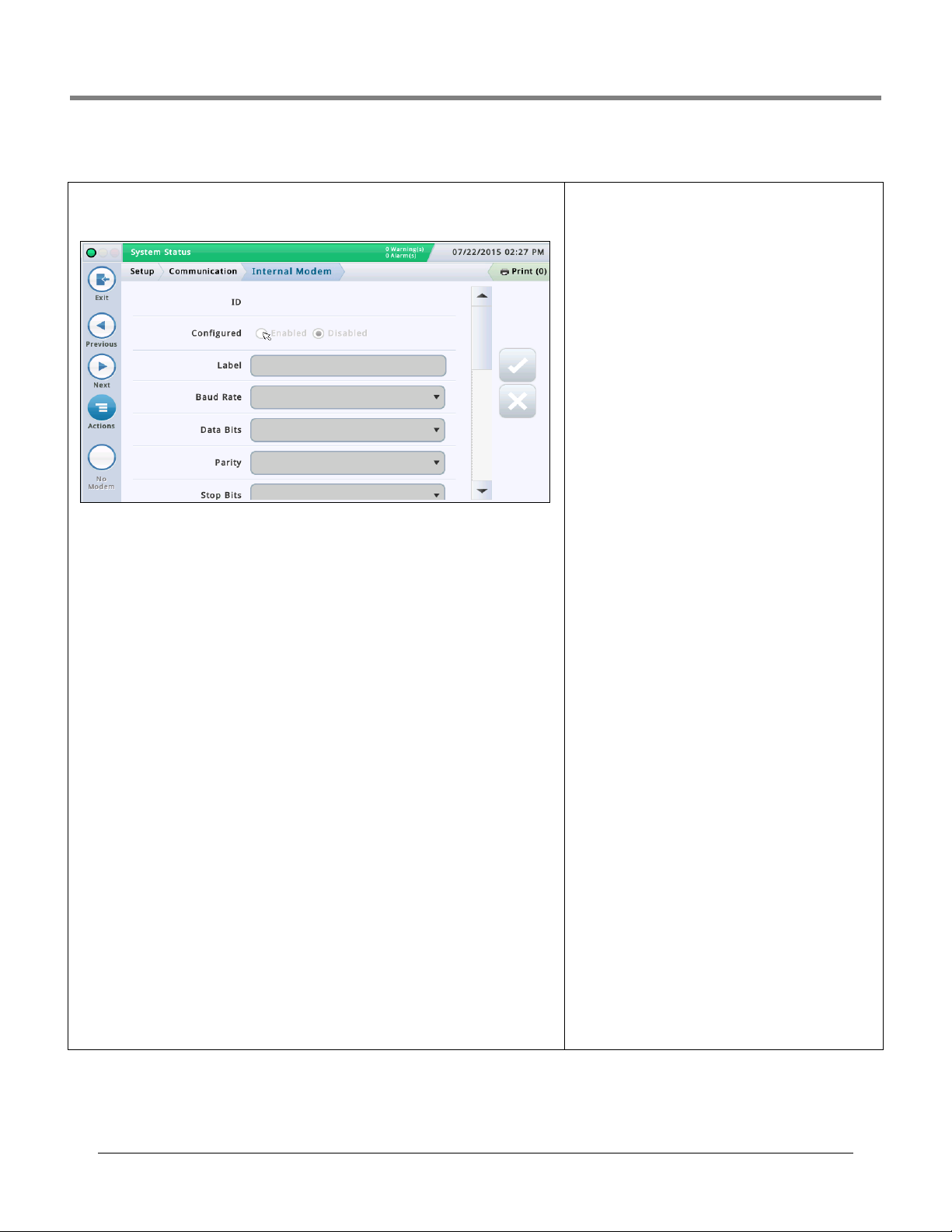
Setup>Communication>Internal Modem
This screen lets you configure the internal modem (TLS-450PLUS consoles only) which is used
for data collection (Note: in the above example screen no internal modem is installed).
Configured
Determines if the internal modem is enabled or disabled.
Label
Name of the internal modem.
Baud Rate
Choices are: 300, 600, 1200, 2400, 4800, 9600, 19200, 38400, 57600, 115200. The default is
9600.
Byte Size/Data Bits
Choices are: 8 or 7
Parity
Choices are: Odd Parity, Even Parity, or None
Stop Bits
Choices are: 1 or 2
Use Handshaking
Choice is: No Handshaking
Modem Dial Type
Choices are: Tone or Pulse
Dial Tone Interval
Choose interval to wait if there is no dial tone: From 0001 to 9999 hours
Answer On
Choose answer on the number of rings selected: From 0 to 9
Dial In Config
Advanced setting. Leave blank unless directed by Support.
Dial Out Config
Advanced setting. Leave blank unless directed by Support.
Serial Command Security
Select Enable to require all incoming serial commands to
have a security code.
Security Code
[Field available and required if Serial Command Security
field is enabled].
This the security code that all serial commands must have
to be accepted by the console. Valid security codes must be
exactly 6 digits (0 - 9) long.
RS232 End of Message
Enables or disables the End of Message RS232 protocol.
This protocol is used by third party devices that may want
to interrogate the console for inventory or other related
data. These devices require an End-Of-Text command that
signals to the device when the communication string from
the console ends.
Please refer to the customer's third party device for the
type of code to enter in the ETX Characters Display and ETX
Characters computer fields below.
ETX Characters Display
[Field enabled only if RSR 232 End of Message field is
enabled]
End-Of-Text (ETX) character. ETX is programmable if
enabled via the S53100f command. If it is disabled, the ETX
is a fixed Control-C character (ASCII 03).
ETX Characters Computer
[Field enabled only if RSR 232 End of Message field is
enabled]
End-Of-Text (ETX) character. ETX is programmable if
enabled via the S53100f command. If it is disabled, the ETX
is a fixed Control-C character (ASCII 03).
14
Page 19

Initial Setup Of The Console Using Workflow Wizard Setup>Communication>CDIM Port
Setup>Communication>CDIM Port
DIM Protocol
This screen lets you configure the DIM protocol for the
optional CDIM (Current Loop Dispenser Interface Module).This module is used by the system to collect dispenser
transactions for the BIR feature.
Select a CDIM port from the icon list on the bottom of the
screen that you want to configure. NOTE: This field will be
grayed out for DIMs that do not support ‘pass-through’ com-
munications.
Touch to select a DIM Protocol. Choices are:
• Gilbarco CL
•Wayne CL
• Unknown
Setup>Communication>TDIM Port
This screen lets you configure the TCP/IP DIM (Dispenser Interface Module) port. This is
used at sites where the console communicates to the dispensers via Ethernet (TCP/IP)
instead of the typical serial communications pathway.
Select a TDIM port from the icon list on the bottom of the screen that you want to configure.
Repeat the entry process for each TDIM Port.
Configured
Touch the radio button to enable or disable this port. NOTE:
When the card is auto-detected, this field will be enabled but
grayed out.
Label
Touch to enter a unique label (up to 20 alphanumeric characters) for the DIM device.
Port Number
Communications port number assigned to this device
(default is 35555). Note: this port is known as the listening
port.
Protocol
Touch to select applicable DIM protocol for your TDIM port.
Choices are:
GilbarcoEDIM, VRProtocolDIM, or Unknown.
Units Reported
Touch to select units for this protocol. Choices are: U.S.,
Metric, or Imperial.
15
Page 20
Initial Setup Of The Console Using Workflow Wizard Setup>Communication>IFSF
System Status
07/07/2016 09:10 AM
0 Warning(s)
0 Alarms(s)
Print (0)
Exit
Actions
Previous
Next
Setup
EnabledConfigured Disabled
Device
LON Module
Communication IFSF
Node Id
01
UDP Port
3485
TCP Port
9000
Setup>Communication>IFSF
This screen lets you configure communication based on International Forecourt Standards
Forum (IFSF) standards for a TLS over TCP/IP or a LonWorks
®
card (LON Module). These
international standards for petroleum retail facilitate the interoperability of service stations
and equipment.
NOTE: A single console cannot support both TCP/IP and LON Module communications simultaneously, even though a site may have a mixed configuration on different consoles. The
maximum number of tanks a site can support is 30.
Configured
Touch the radio button to enable or disable IFSF communication.
Device
The device used for communication. Choices are: LON Module (if installed) or Eth1 for Ethernet Port 1 (for TCP/IP), depending on your hardware configuration.
NOTE: On the TLS450PLUS, Ethernet Ports 2a and 2b are not available for IFSF configuration.
Protocol
The protocol used for IFSF. The choice is: IFSF-China1. This
field is not available with the LON Module device option.
Node Id
The ATG Node Identifier. Each IFSF tank gauge present on a
network must have a unique node ID. The default is 01, but
you can change it as required. This field is not available with
the LON Module device option.
NOTE: With a LonWorks
®
card, the Node ID is set using the
IFSF Node Address Dip Switch on the IFSF Interface Module
during installation. Refer to the Console Troubleshooting
section of the TLS-450PLUS Troubleshooting manual (P/N
577014-075) or the Troubleshooting section of the TLS4 /
8601 Series Consoles Troubleshooting manual (P/N 577014-
058), as appropriate, for more information on IFSF module
cable connector assembly and Node ID switch settings.
UDP Port
The port used for User Datagram Protocol (UDP) communication. The default is 3486, but this field can be edited if you
need to use a different port (1024-65535). This field is not
available with the LON Module device option.
TCP Port
The port used for Transmission Control Protocol (TCP) connection requests. The default is 9000, but this field can be
edited if you need to use a different port (1024-65535). This
field is not available with the LON Module device option.
16
Page 21
Initial Setup Of The Console Using Workflow Wizard Setup>Communication>Serial Port
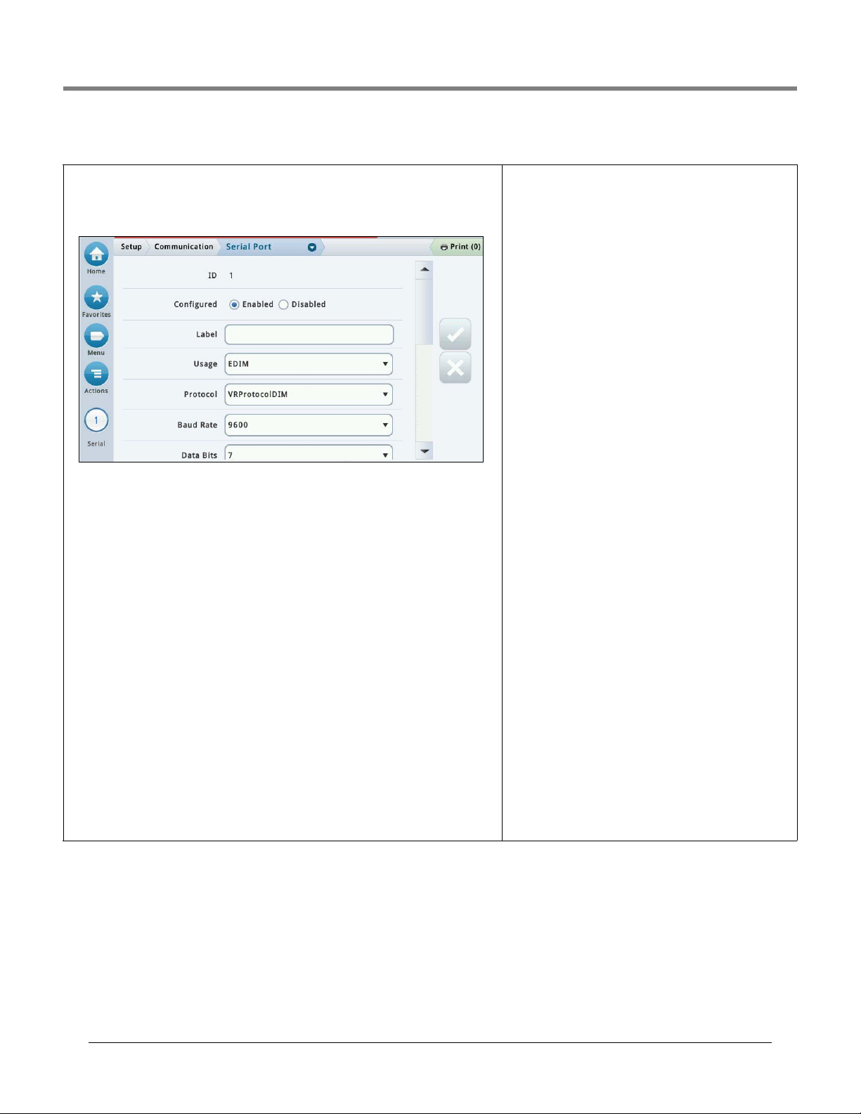
Setup>Communication>Serial Port
This screen lets you configure the serial ports which may be used for data collection or diag-
nostics purposes. Select a serial port from the icon list on the bottom of the screen that you
want to configure. Repeat the entry process for each Serial Port.
Configured
Touch to enable or disable the Serial Port.
Label
Touch to enter a name for this port.
Usage
Touch to select the type of communication card (board) in the console
Choices are: RS-232, RS485, EDIM, Satellite HJBox, Satellite SSAT, VMCI, Digicom GSM.
Protocol (only visible if EDIM is selected for Usage)
Touch to select applicable DIM protocol for your EDIM port.
Choices are: GilbarcoEDIM, VRProtocolDIM, Sinopec EDIM.
Baud Rate
Touch to select the communication data rate of this serial port. Choices are: 300, 600, 1200,
2400, 4800, 9600, 19200, 38400, 57600, 115200. The default is 9600.
Stop Bits
Choices are: 1 or 2
Byte Size/Data Bits
Choices are: 8 or 7
Parity
Choices are: Odd Parity, Even Parity, or None
Use Handshaking
Choice is: No Handshaking, RTSCTS or XON XOFF
Serial Command Security
Select Enable to require all incoming serial commands to
have a security code.
Security Code
[Field available and required if Serial Command Security
field is enabled].
This the security code that all serial commands must have to
be accepted by the console. Valid security codes must be
exactly 6 digits (0 - 9) long.
RS232 End of Message
Enables or disables the End of Message RS232 protocol.
This protocol is used by third party devices that may want to
interrogate the console for inventory or other related data.
These devices require an End-Of-Text command that signals
to the device when the communication string from the console ends.
Please refer to the customer's third party device for the type
of code to enter in the ETX Characters Display and ETX Characters computer fields below.
ETX Characters Display
[Field enabled only if RSR 232 End of Message field is
enabled]
End-Of-Text (ETX) character. ETX is programmable if enabled
via the S53100f command. If it is disabled, the ETX is a fixed
Control-C character (ASCII 03).
ETX Characters Computer
[Field enabled only if RSR 232 End of Message field is
enabled]
End-Of-Text (ETX) character. ETX is programmable if enabled
via the S53100f command. If it is disabled, the ETX is a fixed
Control-C character (ASCII 03).
17
Page 22
Initial Setup Of The Console Using Workflow Wizard Setup>Communication>SMTP Relay
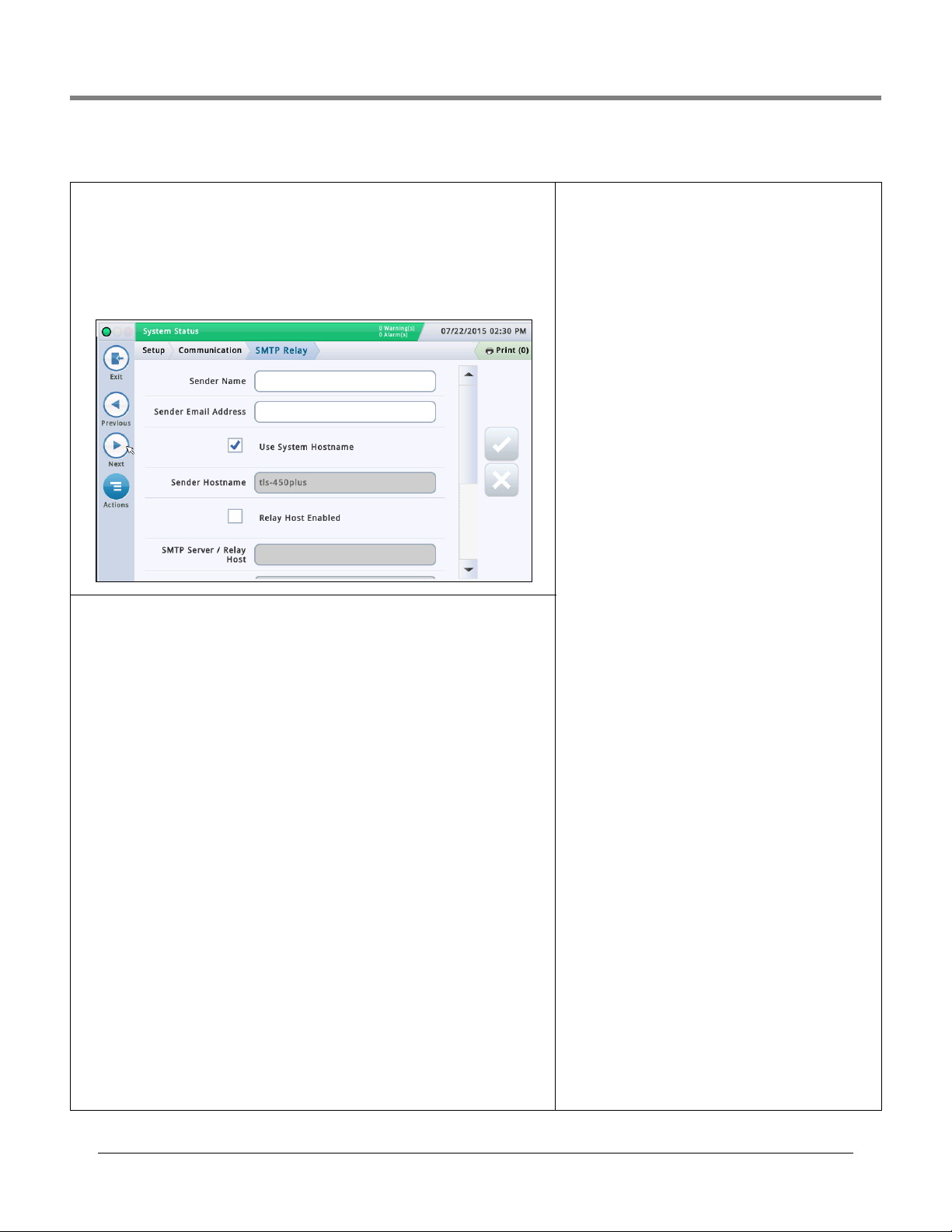
Setup>Communication>SMTP Relay
The system supports Simple Mail Transfer Protocol (SMTP), an Internet standard for email
transmission. This screen lets you configure this feature, which allows the console to act as
a mail client, using SMTP to send messages to a mail server.
NOTES:
1. Some fields require the Total Control Feature.
2. Sender Email Address, System Hostname, SMTP Relay and SMPT Server Password
must be provided by the ISP (Internet service provider).
Sender Name
Touch to enter the name that will display as the sender of the email. Maximum of 40 characters.
Sender Email Address
Touch to enter valid sender’s email address (using the standard format, such as technicalsupport@veeder.com). Maximum of 254 characters.
This entry specifies the originating email address. It also appears in the ‘From:’ header field
within the email message.
NOTE: If you leave this field blank, the email message is set to the Linux account on the console that is sending email, followed by @[hostname].[domainname](your hostname and
domain name).
Use System Hostname
If enabled, the system hostname is used and is displayed below. If disabled, you can enter a
valid hostname in the field below. The default is enabled.
Sender Hostname
Touch to enter the name that is sent to the SMTP server (used for SMTP tasks such as connecting remote mail servers). Some mail servers require a valid Internet hostname when
other mail servers connect. Usually this the hostname that your IP address resolves to and
would be included in the information from your ISP. It should never be the domain name or
the relayhost name.
Relay Host Enabled
If disabled, these fields are not available. If enabled, SMTP is used for email and the following fields are available:
• SMPT server/Relay Host
•Port Number
• Authentication Type
• SMTP Server Username
• SMTP Server Password
• SMTP Server Requires SSL
SMTP Server / Relay Host [Relayhost/Smart
host]
Touch to enter the IP address or hostname of the SMTP
server/relay host that the console is attempting to connect
with. When this field is used, all mail is forwarded through
this host and not sent directly to recipients. NOTE: a URL is
not valid for this field.
SMTP uses this field to determine the appropriate internet
destination. Some ISPs block email traffic until it is sent
through their mail server.
Port Number [Relayhost/Smarthost Port]
The port on the server where the email should be sent. This
field is populated when the SMTP server is entered. The
default port number is 25.
NOTE: if the ‘SMTP Server Requires SSL’ field below is
enabled, this port number should be 465 or 587.
Authentication Type
Touch to enter the type of SMTP authentication that is
required by the remote server:
• No Authentication - no username and password is
required.
• CRAM MD5 - secure transmission of username and password.
Plain - the username and password are sent as human-
•
readible text to the server (without encryption).
• Login - he username and password are sent as humanreadible text to the server (without encryption).
NOTE: you should select the most secure method allowed by
your server. Check with your ISP if you have questions.
SMTP Server Username [Relayhost/Smart
host Server User Name]
Touch to enter the server name for authentication - maxi-
mum 60 characters.
SMTP Server Password [Relayhost/Smart
host Password]
Touch to enter the server password or ‘shared secret’ for
the server - maximum 25 characters.
SMTP Server Requires SSL [Relay Requires
SSL]
When enabled it forces the use of SSL encryption for the
entire session when communicating with the server.
Generally this should not be enabled (checked) because the
console will automatically use SSL encryption if the server
supports it. It should be enabled only for older email servers
where the entire communication must be wrapped in SSL.
This selection should not be enabled for modern servers that
negotiate encryption after connecting or the connection will
fail. If the relay server port number is 25 (default), this
selection should not be enabled.
18
Page 23
Initial Setup Of The Console Using Workflow Wizard Setup>Devices
Actions
1
Probe
Water
Next
Actions
1
Probe
Probe
1 2 3 4
Serial Number
Type
Float Type [inch
Previous
Next
Actions
1
Probe
Probe
1 2 3 4
Address
Label
Serial Number
Type
Float Type [inch
External Input
Liquid Sensor
Type A Sensor
Type B Sensor
Line Pressure Sensor
LVDI M
ATM Pressure Sensor
Vapor Pressure Sensor
Ground Water Sensor
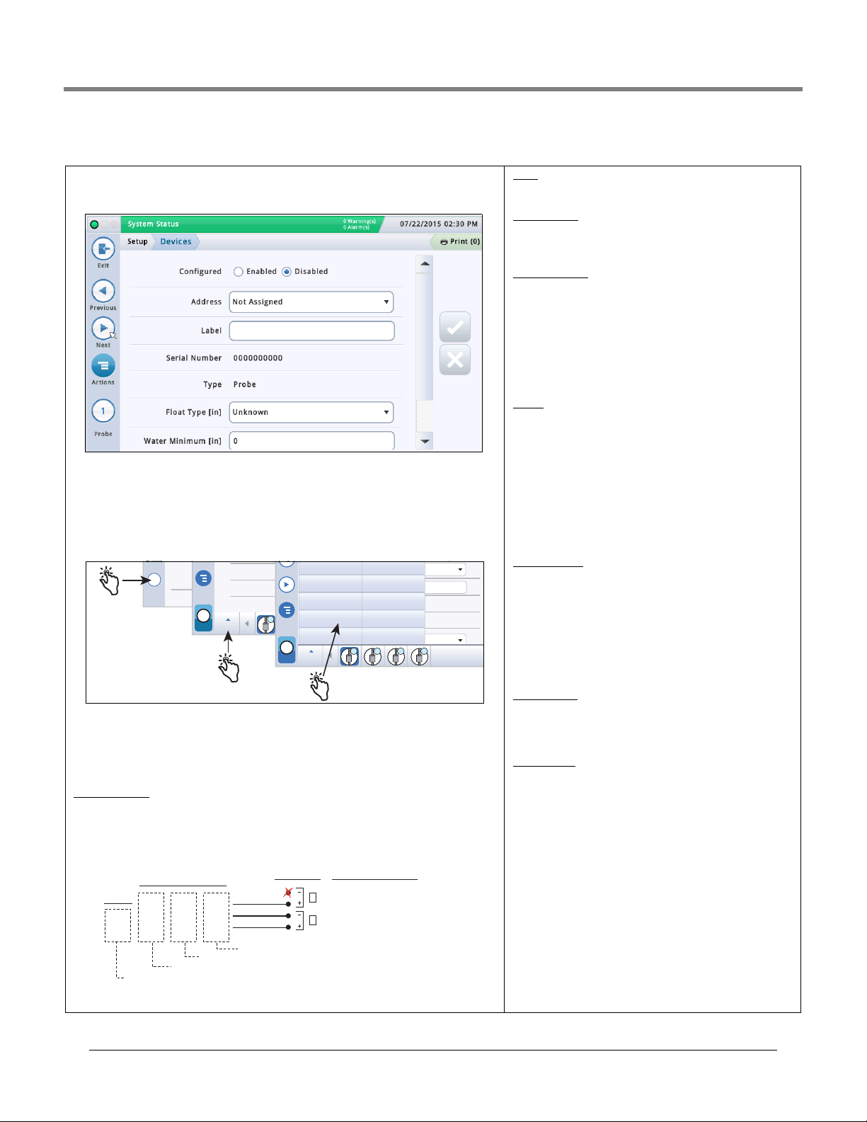
Setup>Devices
The Setup>Device screens let you configure each of the monitored devices that is connected to the console (probes, sensors, relays, external inputs) and (LVDIM/MDIM modules
- TLS-450PLUS only).
Selecting A Device Type
Initially the first device type to be displayed in Workflow Wizard setup is Probe 1. To select
another probe, touch the probe 1 button on the lower left of the screen and select the
desired probe from the icon list along the bottom of the probe device screen. To select
another device type, use the touch sequence shown in the illustration below to view the
device matrix, then touch the desired device type button to open that device’s setup screen.
Selecting A Device Address
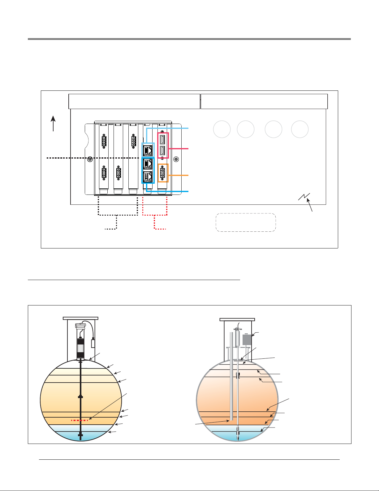
IMPORTANT! You must know to which console connector a device is wired to select the correct address for that device. Some general rules discussed below concern device
addresses.
TLS4 Consoles
Probes/Sensors connected to the console will display the following address code in the
Address Field: B1:S2:X , where x is the connector input to which the device is attached
(from 1 to 16). NOTE: 3-wire sensors require three connector inputs (2 ‘+’ channels and 1 ’
– ‘ channel) so each 3-wire sensor takes up two of the available intrinsically safe ports and
uses two addresses (see 2- and 3-wire connection examples below):
All
2-Wire
Sensors
BLK
WHT*
*Red wire instead of White for:
• Interstitial Sensor - Steel Tanks (794380-4X0)
• CSTP Liquid Switch
• Position Sensitive Interstitial Sensor - Steel Tanks (794380-333)
3-Wire
Sensors
WHT
WHT
RED
BLK
WHT
GRN
GRN
RED
BLK
Groundwater Sensor
Vapor Sensor
4Site Pan/Sump (Type B) - Standard and Optical
Console
Connections
Not used with
3-wire sensor
Example Port Address
Selections
2
B1:S1:2 Address 2 Field Selection
1
B1:S1:1 Address Field Selection
19
Relay will display the following possible address codes in the
Address Field: B1:S1:X , where X = 14 (relay connector
input 1) or 15 (relay connector input 2).
External Input will display the following possible address
codes in the Address Field: B1:S1:X , where X = 12 (Ext.
Input connector input 1) or 13 (Ext. Input connector input 2).
TLS-450PLUS Consoles
Probes/Sensors connected to the console will display the
following possible address ports in the Address Field:
B1:Sx:X, where Sx is the slot in which the USM module is
installed (from 1 to 4) and X is the connector input to which
the device is attached (from 1 to 16). NOTE: 3-wire sensors
require three connector inputs (2 ‘+’ channels and 1’ – ‘
channel) so each 3-wire sensor takes up two of the available
intrinsically safe ports and has two addresses (Address field
and Address 2 field (see 3-Wire Sensor Addresses Example
illustration above).
Relays connected to the I/O module will display the following possible address codes in the Address Field: B1:Sx:X,
where Sx is the slot in which the I/O module is installed
(from 1 to 4) and X is the connector input to which the device
is attached (from 5 to 9). Note: The relay address B1:S7:1
refers to the single input Power Bay relay which, if used,
would connect to the site’s Overfill Alarm.
Relays connected to a 10 AMP Controller module will display
the following possible address codes in the Address Field:
B1:S4x:X, where S4 is the only slot in which the 10 AMP Controller module is installed and X is the connector input to
which the device is attached (from 1 to 6).
External Inputs
connected to the I/O module will display the
following possible address codes in the Address Field:
B1:Sx:X, where Sx is the slot in which the I/O module is
installed (from 1 to 4) and X is the connector input to which
the device is attached (from 1 to 4 and 10 to 14).
External inputs connected to a 10 AMP Controller module will
display the following possible address codes in the Address
Field: B1:S4x:X, where S4 is the only slot in which the 10
AMP Controller module is installed and X is the connector
input to which the device is attached (from 7 to 12).
LVDIM inputs
connected to the console will display the following possible address codes in the Address Field: B1:Sx:X,
where Sx is the slot in which the LVDIM module is installed
(from 1 to 4) and X is the connector input to which the device
is attached (from 1 to 12).
MDIM inputs connected to the console will display the following possible address codes in the Address Field: B1:Sx:X,
where Sx is the slot in which the MDIM module is installed
(from 1 to 4) and X is the connector input to which the device
is attached (from 1 to 12).
Page 24
Initial Setup Of The Console Using Workflow Wizard Setup>Devices
waterfloat
densitywaterfloat(1.5inch
minimumwaterlevel)
densitywaterfloat(1inch
minimumwaterlevel)
B7053686719512
S/N: 13240161
Example Density Code
Example Serial Number
Setup>Devices - Continued
PROBE SETUP
Set up each probe being monitored before selecting the next device type.
Configured
Touch the radio button to enable or disable configuration of the selected
probe.
NOTES:
Do not enable probe configuration until its address is assigned!
•
• Once enabled, do not disable a probe if it is assigned to a tank. You must
first unassign the probe from the tank before the probe can be disabled.
(see Setup > Tank > General).
Address
Touch and select the address of this probe.
Label
Touch to enter a description of this probe (up to 20 alphanumeric characters)
that will appear on the console screens and in reports.
Serial Number
[Read Only] Console auto-detected serial number of this device.
Type
[Read Only] Console auto-detected type of this device.
Float Type
Installed Mag probe float type (the console will display only the applicable
float size options for this device). For example, depending on the probe
installed the float sizes below could display in the drop down list:
•4.0in •4.0inphaseseparation •3.0in
•2.0innon‐density
•Custom
NOTES:
• Only circuit codes D004, D005 and D006 are allowed to set the float type to
4.0 in phase separation.
• If the probe is changed and the previous float is supported by the new
probe, the float assignment will remain the same. Otherwise the default
float will be assigned to the new probe.
• Only select Custom if the literature that was shipped with probe float kit
specifically states that you must choose this Float Type. Currently only
three mag probes use Custom Float Types: Chem-ISO mag probes, LPG-ISO
mag probes and the Mag-FLEX probe with low level water floats.
When Custom float type is selected, the Fuel Offset, Water Offset, Water
Minimum and Invalid Fuel parameter fields below are enabled for edit.
Refer to the appropriate installation kit manual for these entries (see
“Related Documents” on page 1).
Fuel Offset -Touch to enter the Fuel Offset value listed in the appropriate
kit manual (577013-770, 577013-773 or 577014-056).
Water Offset (Mag-FLEX probes with Low Level Water Float only) Touch to enter the Water Offset value listed in the 577014-056 manual.
Water Minimum (Mag-FLEX probes with Low Level Water Float only) Touch to enter the Water Minimum value listed in the 577014-056 manual.
Invalid Fuel - Touch to enter the Invalid Fuel value listed in the appropriate kit manual (577013-770, 577013-773 or 577014-056).
•2.0instandard‐standard
•2.0inlowwater‐ lowwater
Density Code
This field stores specifications for a density probe. It must be exactly 14
characters, and is composed of four parts as described below:
The density code has the following format: FGGGGGGMMMMDDD, e.g.,
B7053686719512, and is impressed in the float body (see image below).
Where:
F = Fuel Type: A for gasoline and B for diesel.
Using the example density code above: B = Diesel, G = Gauss
The last two digits are the gauss readings for each magnet in the den-
sity float. The prefix is always 7 and is omitted from the density code.
Using the example density code above:
70 Gauss = 77.0
53 Gauss = 75.3
for top magnet in grams
for middle magnet in grams
68 Gauss = 76.8 for bottom magnet in grams
M = Mass
The last four digits of the mass of the float. The prefix is always 1 and is
omitted from the density code.
Using the example density code above:
6719 = Mass of 16.719
grams
D = Density of the float
The prefix is dependent on the fuel type and is omitted from the density
code. A = 7 (gasoline) and B = 8 (diesel).
Using the example density code above:
512 = density of 851.2
kg/m3 for a fuel type of diesel.
NOTE: If you change the Density Code, the Density Offset History is
cleared and current Density Offset is set to zero. See Diagnostics>
Probe>Density Offset screen for details on console density values.
Density Float Serial Number
Touch this field to enter the density float’s serial number.
NOTE: if you change the density float serial number, the Density Offset
History is cleared and the current Density Offset is reset to zero.
The density float serial number has the following format - yywwxxxx,
e.g., 13240161, and is impressed in the float body (see image below).
Where;
YY = the last two digits of the year it was manufactured’
WW = the number of the week it was manufactured,
XXXX = a unique integer for the density float
20
Page 25

Initial Setup Of The Console Using Workflow Wizard Setup>Devices
Setup>Devices - Continued
RELAY SETUP
Set up each relay being monitored before selecting the next device type.
Configured
Touch the radio button to enable or disable configuration of the selected
relay.
Address
Touch and select the address of this relay.
Label
Touch to enter a description of this relay (up to 20 alphanumeric characters)
that will appear on the console screens and in reports.
Relay Type
Touch to select relay type:
• Standard - On/Off state is determined by assigned alarms or warnings.
• Momentary - On/Off state is determined by the assigned alarms or warnings (relay returns to the inactive state after the alarm is acknowledged).
Pump Control Output - Relay state is controlled by the console pump/
•
line controller (TLS-450PLUS only).
Relay Orientation
Touch to select relay orientation:
•Normally Open
•Normally Closed
EXTERNAL INPUT SETUP
Set up each external input being monitored before selecting the next device
type.
Configured
Touch the radio button to enable or disable configuration of the selected
external input.
Address
Touch and select the address of this external input.
Label
Touch to enter a description of this external input (up to 20 alphanumeric
characters) that will appear on the console screens and in reports.
Type
Touch to select external input type:
Standard - Generates an external input alarm when it is active.
•
•
Generator - Generates the ON and OFF messages for CSLD on a genera-
tor.
Pump Sense - Indicates the On/Off state and the state of hook signal for
•
a dispenser and also is used to configure PLLD (TLS-450PLUS only);
Acknowledge Alarm - External Input is used as an ALARM/TEST key (for
•
example, a remote push button) and also generates the external input
alarm.
•
Pump Relay Monitor [Available with PLLD] - Generates a pump relay
alarm when the console suspects a relay is stuck closed or when the pump
has been running continuously for a period exceeding the Max Run (set in
“Setup>Pumps and Lines>PLLD”) (TLS-450PLUS only).
Orientation
Touch to select External Input orientation:
•Normally Open
•Normally Closed
LIQUID SENSOR SETUP
Set up each liquid sensor being monitored before selecting the next device
type.
Configured
Touch the radio button to enable or disable configuration of the selected liquid sensor.
Address
Touch and select the address of this liquid sensor.
Label
Touch to enter a description of this liquid sensor (up to 20 alphanumeric
characters) that will appear on the console screens and in reports.
Model
Touch and select the model of this liquid sensor:
• Tri-State (Single Float) - Single float, liquid sensor.
• Normally Closed - Liquid sensor whose normal state is closed, and activates an alarm when it is in an open state (NOT recommended).
Dual Point Hydrostatic - Liquid sensor used in liquid-filled, double-wall
•
tanks.
• Dual Float Discriminating - Liquid sensor with two floats, discriminates
between water and fuel, generally used in containment sumps.
• Dual Float High Vapor - Liquid sensor with two floats, discriminates
between high and low vapor, generally used in containment sumps.
Interceptor Sensor - European type, liquid sensor.
•
Category
Touch to select liquid sensor category:
• Annular Space • Dispenser Pan • Monitoring Well •STP Pump
•Containment Pump •Other
TYPE A SENSOR (2-WIRE CL) SETUP
Set up each Type A sensor being monitored before selecting the next device
type.
Configured
Touch the radio button to enable or disable configuration of the selected
Type A sensor.
Address
Touch and select the address of this Type A sensor.
Label
Touch to enter a description of this Type A sensor (up to 20 alphanumeric
characters) that will appear on the console screens and in reports.
Model
Touch and select the model of this Type A sensor:
Discriminating Interstitial - Discriminating sensor used in dry, double-
•
wall tanks.
•
Ultra 2 - Older version of discriminating sensor used in dry, double-wall
tanks.
Category
Touch to select Type A sensor category:
• Annular Space • Dispenser Pan • Monitoring Well • STP Pump
•Containment Pump • Other
21
Page 26

Initial Setup Of The Console Using Workflow Wizard Setup>Devices
Setup>Devices - Continued
TYPE B SENSOR (3-WIRE CL) SETUP
Set up each Type B sensor being monitored before selecting the next device
type.
Configured
Touch the radio button to enable or disable configuration of the selected
Type B sensor.
Address
Touch and select address 1 of the 3-wire Type B sensor.
Label
Touch to enter a description of this Type B sensor (up to 20 alphanumeric
characters) that will appear on the console screens and in reports.
Address 2
Touch and select the next sequential address for the third wire of the Type B
sensor (e.g., if the Address field above is B1:S2:2, then this address should
be B1:S2:3).
Model
Touch and select the model of this Type B sensor:
Ultra/Z-1 - 4Site Pan/Sump - Standard.
•
• Ultra/Z-1 HV - 4Site Pan/Sump - High Vapor.
Category
Touch to select Type B sensor category:
• Annular Space •Dispenser Pan • Monitoring Well • STP Pump
•Containment Pump •Other
MAG SENSOR SETUP
Set up each Mag sensor being monitored before selecting the next device
type.
Configured
Touch the radio button to enable or disable configuration of the selected Mag
sensor.
Address
Touch and select the address of this Mag sensor.
Label
Touch to enter a description of this Mag sensor (up to 20 alphanumeric characters) that will appear on the console screens and in reports.
Serial Number
[Read Only] Console auto-detected serial number of this Mag sensor.
Alarm Delay
Touch to enter the time in hours following the triggering of un-cleared warnings before they are upgraded to alarms.
Fuel Alarm
Touch to enter the height at which this Mag sensor will activate the fuel
alarm.
Fuel Warning
Touch to enter the height at which this Mag sensor will activate the fuel
warning.
Water Alarm
Touch to enter the height at which this Mag sensor will activate the water
alarm.
MAG SENSOR SETUP - Concluded
Water Warning
Touch to enter the height at which this Mag sensor will activate the water
warning.
GROUNDWATER SENSOR SETUP
Set up each groundwater sensor being monitored before selecting the next
device type.
Configured
Touch the radio button to enable or disable configuration of the selected
groundwater sensor.
Address
Touch and select address 1 of the 3-wire groundwater sensor.
Label
Touch to enter a description of this groundwater sensor (up to 20 alphanumeric characters) that will appear on the console screens and in reports.
Address 2
Touch and select the next sequential address for the third wire of the
groundwater sensor (e.g., if the Address field above is B1:S2:4, then this
address should be B1:S2:5).
Category
Touch to select this groundwater sensor category:
• Annular Space • Dispenser Pan • Monitoring Well • STP Pump
•Containment Pump •Other
VAPOR SENSOR SETUP
Set up each vapor sensor being monitored before selecting the next device
type.
Configured
Touch the radio button to enable or disable configuration of the selected
groundwater sensor.
Address
Touch and select address 1 of the 3-wire vapor sensor.
Label
Touch to enter a description of this vapor sensor (up to 20 alphanumeric
characters) that will appear on the console screens and in reports.
Address 2
Touch and select the next sequential address for the third wire of the
vapor sensor (e.g., if the
Address field above is B1:S2:6, then this
address should be B1:S2:7).
Threshold
Touch to enter the vapor level which identifies a leak or serious spillover and
that triggers the vapor alarm. Thresholds are in ohms and must be calculated for each vapor sensor (see Vapor Sensor Threshold topic for determin-
ing value).
Category
Touch to select this vapor sensor category:
• Annular Space • Dispenser Pan • Monitoring Well • STP Pump
•Containment Pump • Other
22
Page 27

Initial Setup Of The Console Using Workflow Wizard Setup>Devices
Setup>Devices - Concluded
LINE PRESSURE SENSOR SETUP
Set up each line pressure sensor being monitored before selecting the next
device type.
Configured
Touch the radio button to enable or disable configuration of the selected line
pressure sensor.
Address
Touch and select the address of this line pressure sensor.
Label
Touch to enter a description of this line pressure sensor (up to 20 alphanumeric characters) that will appear on the console screens and in reports.
Serial Number
[Read Only] Console auto-detected serial number of this line pressure sensor.
ATM PRESSURE SENSOR SETUP
Set up each ATM pressure sensor being monitored before selecting the next
device type.
Configured
Touch the radio button to enable or disable configuration of the selected ATM
pressure sensor.
Address
Touch and select the address of this ATM pressure sensor.
Label
Touch to enter a description of this ATM pressure sensor (up to 20 alphanumeric characters) that will appear on the console screens and in reports.
Serial Number
[Read Only] Console auto-detected serial number of this ATM pressure sensor.
VAPOR PRESSURE SENSOR SETUP
Set up each vapor pressure sensor being monitored before selecting the
next device type.
Configured
Touch the radio button to enable or disable configuration of the selected
vapor pressure sensor.
Address
Touch and select the address of this vapor pressure sensor.
Label
Touch to enter a description of this vapor pressure sensor (up to 20 alphanumeric characters) that will appear on the console screens and in reports.
Serial Number
[Read Only] Console auto-detected serial number of this vapor pressure
sensor.
LVDIM/MDIM SETUP (TLS-450PLUS only)
Configured
Touch the radio button to enable or disable configuration of the selected
LVDIM/MDIM input.
Address
Touch and select the address of this LVDIM/MDIM input.
Label
Touch to enter a description of this LVDIM/MDIM input (up to 20 alphanumeric characters) that will appear on the console screens and in reports.
Unit Conversion
Touch to select US, Imperial, or Metric units.
Pulse Conversion
Touch to select the number of pulses per unit volume.
23
Page 28

Initial Setup Of The Console Using Workflow Wizard Setup>BIR>General
Setup>BIR>General
In this screen you set up reconciliation parameters for your inventory reports if the BIR
function is enabled (ref. “Meter Data Present” on page 26).
Product Threshold Alarm
Touch to enable an alarm that is triggered when your periodic reconciliation data exceeds a
preset product threshold value (see Setup > BIR > Threshold Alarms for details about this
alarm).
Daily Close Time
Touch to enter a time when you want the system to store the data for the current day
(default is 02:00 AM).
BIR needs approximately 2-5 minutes of quiet time to generate a report. Because 2:00 AM is
normally the quietest time of the day, we recommend using that time (unless there is a business need to do it at another time).
Week Close Time
Touch to enter the Day of the week when you want the system to store the data for the current week (used in weekly reports.
Alarm Threshold Delivery Type
Touch to select how the BIR variance amount is calculated:
• Standard - does not use delivery receipts in the BIR variance amount calculation.
Ticketed Delivery - uses delivery receipts in the BIR variance amount calculation. Select
•
this if the ticketed delivery feature is enabled in the Setup>Delivery screen.
Temperature Compensation
Touch to enter the method for calculating BIR volumes:
• Standard - use when the meters are not temperature
compensated (TC).
TC Volume - use when meters are temperature compen-
•
sated (TC).
Meter Calibraton Offset %
If you have meters that require a calibration offset, use this
field to enter a meter calibration % to compensate (applies
to all dispenser meters and is used in the calculated dispensed amount). For most domestic (US) sites, the default of
0% is fine.
BIR Daily Close Warning Enable
Touch the radio button to enable or disable the posting of
this warning when the BIR daily close cannot occur at the
scheduled time.
BIR Status Warning Enable
Touch the radio button to enable or disable the posting of
this warning when conditions occur that may impact the reconciliation variance (such as meter map incomplete, meter
map unstable, invalid fuel height, probe out, tank chart
changed, DIM queue overrun).
BIR Shift Enable
Touch the radio button to enable or disable the posting of
this warning when the BIR shift close cannot occur at the
scheduled time (a BIR shift close could be delayed when a
delivery is in progress, a dispense is in progress, the station
is too busy, etc.).
24
Page 29

Initial Setup Of The Console Using Workflow Wizard Setup>BIR>Threshold Alarm
Setup>BIR>Threshold Alarm
In this screen you can configure up to four reconciliation alarms per tank based on Throughput, Capacity, Deliveries and Fixed Values. You can also select a specific test method that will
be used to post the selected threshold alarm. The choices in this screen are only allowed if
the Product Threshold alarm is enabled in the “Setup>BIR>General” screen above.
Test Ty pe
Touch to select a monitoring period option for the selected test protocol:
• Disabled - Test is disabled.
Monthly - Threshold is compared against the monthly variance summation over a calen-
•
dar month. This test is performed monthly and generates one report per monitoring
period.
Rolling - Threshold is compared to the variance summation over the defined number of
•
days you enter in the Rolling Days field. The test is performed daily, but a single report is
generated at the end of the monitoring period (i.,e., the Rolling Days entry).
• Daily - Daily variance is compared to the threshold.This test is performed daily and a
report is generated daily.
Rolling Consecutive - Rolling Consecutive monitors the variance during the period
•
entered in the Rolling Days field. The first report is generated at the end of the monitored
Rolling Days period. Thereafter, a report is generated each day for the monitored Rolling
Days period. For example, you select Rolling Consecutive test type and enter 10 in Rolling
Days field. The test starts March 1. On March 10 a report is generated for days March 1 March 10. On March 11 the next report is generated for days March 2 - March 11 (the Rolling Days period), and so on, each report covering the last 10 days.
Rolling Days
[Only available when Rolling Consecutive is chosen above] Touch to enter the number of
rolling days.
Throughput
Touch the radio button to enable or disable this threshold
alarm.
%
- Touch to enter the percentage amount of metered sales
or throughput (typically 1%).
Volume Offset - Touch to enter the offset amount (e.g.,
130 gallons or 492 liters) added to the % of throughput value
above to trigger BIR variance threshold alarm.
Capacity
Touch the radio button to enable or disable this threshold
alarm.
%
- Touch to enter a percentage amount of tank capacity
(typically 1%).
Volume Offset - Touch to enter the offset amount (e.g.,
130 gallons or 492 liters) added to the % of tank capacity
value above to trigger BIR variance threshold alarm.
Deliveries
Touch the radio button to enable or disable this threshold
alarm.
- Touch to enter a percentage amount of deliveries (typi-
%
cally 1%).
Volume Offset - Touch to enter the offset amount (e.g.,
130 gallons or 492 liters) added to the % of deliveries values
above to trigger BIR variance threshold alarm.
Fixed Values
Touch the radio button to enable or disable this threshold
alarm.
Value - Touch to enter a A fixed amount (e.g., 130 gallons or
492 liters) that triggers the BIR variance threshold alarm.
25
Page 30

Initial Setup Of The Console Using Workflow Wizard Setup>Tank>General
Setup>Tank>General
Full Volume (Capacity)
Touch to enter the full volume of the tank at 100% height
(this volume is provided by the tank manufacturer).
Diameter
Touch to enter the inside diameter of the tank (look for this
dimension on the tank chart provided by the manufacturer).
Tank Tilt
Touch to enter the amount of offset (in inches [mm]) of the
tank from a perfect horizontal. For an explanation of tank tilt
and how to calculate this value, see Actions>Help>Reference Tables>Tank Tilt Calculation.
NOTES:
• If the probe is installed in the center of the tank, enter a
value of 0.00.
• Tank Tilt may be a positive (+) or negative (-) value. If it is
a negative value, make sure to change the value symbol to
minus (-) when entering a negative tank tilt value.
Thermal Coefficient
Configured
Touch the radio button to enable or disable the tank.
NOTE: Set to Enabled only after completing all of the Setup>Tank screens.
Label
Touch to enter a description for the tank (normally based on the name of the product in the
tank and should be unique for each tank).
NOTE: This field is not the same as the label associated with the product, which is assigned
Setup > Product > Labels screen.
in the
Product Code
Touch to enter an alphanumeric code for a POS terminal used to identify the product for
inventory control purposes. This typically defaults to the corresponding tank number, such as
T1 and PC 1.
NOTE: There are instances when you may want to override the default value provided and
enter a different code. For example, in BIR, you may have two tanks that have the same
product type. In this case, you would want to program the same product code the for each
tank. By manually entering in the correct code, you would ensure BIR is presenting the correct data for the product type..
Product Color
Touch and select a color that represents this product when displayed on screen.
Probe
Touch to enter an Identifier of the installed probe (as set up in “Setup>Devices”). A probe
assignment to a tank is one to one:
• Probe 1 is assigned to tank 1
• Probe 2 is assigned to tank 2
•etc.
Probe Offset
The probe offset value is the distance the probe is off the bottom of the tank and helps to
obtain an accurate measurement of fuel in the tank.
In console calculations, the probe offset value is always added to the product height value
when product height is displayed (for example, in Overview>Tank Detail).
Touch to enter a value compensating for probes that are not resting on the bottom of the
tank.
Touch to enter a value representing the coefficient of thermal expansion for the fuel in the tank. This value provides
the proper expansion and contraction rate for a particular
product type. If this value is entered incorrectly, it impacts
inventory and tank test results. For a list of thermal coefficients, see Actions>Help> Reference Tables>Thermal
Coefficients.
NOTE: Make sure you enter the correct value. If you
are off by one decimal point, it can substantially affect
system calculations.
Meter Data Present
For the selected tank, touch the radio button to enable or
disable BIR software* to collect dispenser transaction data
from the meters. (Note: BIR monitors data only from tanks
assigned to Mag probes 1 to 32).
NOTE: Do not enable unless the Veeder-Root electronic Dispenser Interface Module (DIM) or current loop Dispenser
Interface Module (DIM) are connected properly to the console.
*BIR option required
Pump Threshold %
[Field enabled when using line manifolded tanks and the
Dispense Mode field is set to ‘Manifolded:Sequential’ in
“Setup>Pumps and Lines>Line”].
When the tank volume drops below the pump threshold percentage entered in this field, pumping will switch over imme-
diately to the next available tank in the line-manifolded line.
Pumping will continue from the current tank for another 10
seconds to avoid a disruption in any dispenser during the
switch-over.
26
Page 31

Initial Setup Of The Console Using Workflow Wizard Setup>Tank>General
Setup>Tank>General - Concluded
Stick Height Offset
[Field available only if Stick Height is enabled in S“Setup>Tank>All
Tanks”].
The value This value compensates for the difference between the stick (no
tilt) and the gage. The difference is due to the stick and the probe measuring
slightly different locations in a tilted tank since the riser used for the stick
measurement is different than the riser used for the probe.
Offset values can be +144 to -144 inches (+365.76 to -365.76 cm).
The stick height equals the tank height (without the tilt), plus the stick height
offset. However, if the calculated stick height is greater than the tank diame-
ter, the stick height is set to the tank diameter. If the stick height is less than
zero, it will be set to zero.
NOTE: All displays of height include tilt. When determining the stick offset,
the tilt adder must be taken into account.
Stick height is not used for volume calculation; it is for display only.
Delivery Delay
Because the system has the ability to detect a delivery automatically, the
time entered in this field represents the delay (in minutes, usually 5 - 10)
after the actual delivery and before the console indicates that a delivery is
complete. This delay provides extra time for the fuel level to stabilize, preventing false alarms and warnings and ensuring a more accurate delivery
report.
Gross Test Fail
Touch to enable or disable the alarm that triggers when a Gross Test [(1.5
gph (5.8 lph)] leak test fails.
Periodic Test Fail
Touch to enable or disable the alarm that triggers when a Period [0.2 gph
(0.76lph)] leak test fails.
Annual Test Fail
Touch to enable or disable the alarm that triggers when the Annual [0.1 gph
(0.38lph)] leak test fails.
GOST Volume Correction
Touch to enable or disable the GOST R 8.595 correction factor that adjusts
the volume calculation of fuel in the tank. When you enable this field, the system automatically adjusts all volume calculations for this tank based on the
temperature of the fuel (mainly used in Eastern Europe and Russia).
27
Page 32
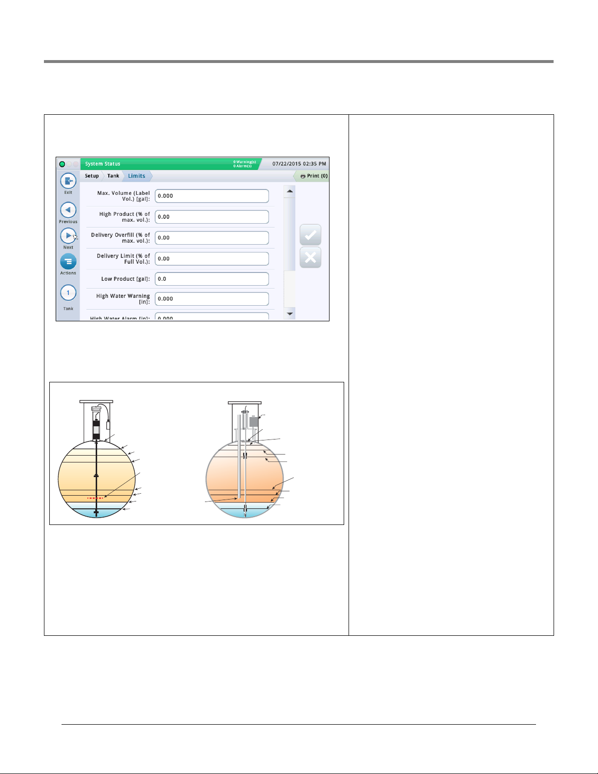
Initial Setup Of The Console Using Workflow Wizard Setup>Tank>Limits
High Water Warning
High Water Alarm
Low Product
Delivery Overfill
Delivery Overfill
High Product
Max (Label) Volume
Full Volume (Ref.)
Full Volume (Ref.)
Pump Inlet (Ref.)
Delivery Limit
Delivery Limit
SAFE WORKING CAPACITY
Maximum Product Alarm Level
("Label" Volume)
High Product Alarm Level
Fuel Draw
Off Level
(Ref.)
High Water Warning Level
Low Product Alarm Level
High Water Alarm Level
Interstitial Sensor/Sump Sensor
Typical European TankTypical North American Tank
Setup>Tank>Limits
This screen lets you enter tank capacity and tank alarm set points. These tank limits provide
the ability for the system to warn of conditions that may arise that need immediate addressing. When programming tank limits, the customer should discuss their needs with a VeederRoot representative to determine these levels.
Max. Volume (Label Vol.)
Set this value at 100% of the tank’s capacity (see alarm references diagram below). The
maximum volume or label volume alarms occur when the level of fluid in the tank exceeds
the value entered in this field.
High Product (% of max. vol.)
High Product alarms occur when the volume of fluid in the tank exceeds the value you enter
in this field, typically set to 95%.
In U.S. installations, this is especially useful in applications such as in used-oil holding tanks,
where the rate of fill can be too gradual for the system to recognize the increase as a delivery and possibly fail to activate the Delivery Overfill Limit Alarm.
In International Sites this field is useful to warn of an impending over-fill (it can trigger the
same alarm indications as Overfill Limit):
• Set this limit to 98% if the Maximum (Label) Volume value is greater than 25,000 liters.
• Set this limit to 96% if the Maximum (Label) Volume value is less than 25,000 liters.
Delivery Overfill (% of Max. Volume)
Delivery overfill alarms alert you to potential overfill conditions during a delivery. When the volume reaches this value,
the console can activate an overfill alarm and can trigger a
printout showing the tank number, date, time, and product.
Set this percentage no greater than 90% of the tank capacity.
For International Sites, set this percentage to no greater
than 99% of maximum (label) Volume.
Delivery Limit (% of Full Volume)
Delivery limit alarms occur when the volume of product in
the tank drops to a level at which you should request a delivery. This is referred to as the minimum operating capacity.
Set this value at a volume higher than that of the Low Product Volume field.
Low Product
Low product is typically used to indicate that the inventory is
at a critical point and the operator/owner should consider
taking the tank out of service until a delivery is made. Normally, this is set around 5-10% of the tank's capacity. A Low
Product alarms alert you when the volume in the tank drops
to the low product level.
International Sites
Assuming no water is present in the tank, this limit should be
set no lower than minimum volumes that can be measured
by each probe type:
•The tank volume at 250mm for Mag probe type 8473
•The tank volume at 125mm for Mag probe type 8493
High Water Warning
When you have a Mag probe with water detection, you can
set this threshold to provide a warning condition when water
enters the tank. In the United States, there is a requirement
to know when and how much water you have in the tank.
Typical water warning setting is 2 inches and is lower than
the high water alarm.
NOTE: This message does not appear for tanks in which high
alcohol probes are installed.
High Water Alarm
When water in the tank rises to the high water alarm value,
the console triggers an alarm. Set this value at a level lower
than the pickup for the submersible pump or suction line.
NOTE: This message does not appear for tanks in which high
alcohol probes are installed.
- Continued on next page
28
Page 33

Initial Setup Of The Console Using Workflow Wizard Setup>Tank>Limits - Concluded
Setup>Tank>Limits - Concluded
Water Alarm Filter Level
During the delivery process, turbulence may be generated in the tanks that
may cause the water float to rise above the water alarm thresholds and trig-
ger false water alarms. In addition, a delivery of fuel containing water and/
or surface water flooding the area and entering the tank through a riser or
other opening may result in significant quantities of water entering the
underground tanks.The Water Alarm Filter Level feature increases the system’s ability to respond to all of these situations. This field provides three
choices of filtering:
Low - This is the quickest response to either flooding or water delivery sce-
narios and is the default choice. The water alarm will be reported 3 minutes
after the water level has crossed the programmed threshold. A delivery may
be in progress during this alarm.
Medium - This level disables the water/alarm monitor during a delivery.
The delivery detection threshold will be set to 25 GPM. This will be small
enough to detect most deliveries and large enough to not mistakenly identify
a delivery when water is leaking into a tank during a flooding situation. This
filter will only be applied to the water alarm.
High - The level follows the same behavior as the medium level filter. The
delivery activity detection rate is raised to 6 GPM; (roughly equivalent to the
current delivery detection rate). The maximum Wait Time will be increased
to 45 Minutes and the Maximum Height Value will be increased to 10 inches.
NOTE: Adjustments to the delivery fill tube may eliminate false water alarms
caused by delivery turbulence.
See Actions>Help>Understanding ATG>Water Alarm Filter Level for more
on this subject.
Leak Alarm Limit
[Applies to SLD tests only]
During a leak test, the leak alarm limit alerts you when the cumulative tem-
perature compensated (TC) product loss from a tank reaches the leak alarm
limit value and helps identify large losses of product during a leak test.
To prevent false reports and alarms from being triggered, do not set the limit
value to identify losses of 0.2 gph (0.76 lph) or less during the test period.
The leak alarm limit should be set to identify losses of 1 gph (4 lph) or
greater.
Consider both the leak rate you wish to identify, and the length of the test,
when determining a value for leak alarm limit. For example, a value of 8 gallons (32 liters) will warn of:
• A 1 gph (4 lph) leak in 8 hours
• A 2 gph (8 lph) leak in 4 hours
NOTE: The console automatically interprets the limit you enter as a negative.
It is not necessary to enter the minus (-) sign.
Sudden Loss Limit
[Applies to SLD and Timed Sudden Loss Detection (TSLD) tests only]
This value allows the system to look for significant losses during a quiet
period to determine if the tank is leaking or fuel has left the tank (e.g., by
bypassing the dispenser meters). It is not based on TC Volume and is
intended to identify losses larger than the leak alarm limit. The default is 99
gallons (374.7 liters) but can be set to 1 to 999,999 gallons (3.78 to 3781.63
liters). Typically, you should set this limit to 25 gallons (100 liters) or higher.
If you are getting too many false alarms, consider increasing this limit.
Note: Siphoned-manifolded tanks are monitored as a single tank. The Sudden Loss Limit threshold is the sum of the thresholds for each member of the
manifolded set.
Density Low Limit
[Field only available if density probe is installed]
Triggers density warning (when greater than the value you enter here plus
1.00kg/m3 (0.062 lbs/ft3) and a density alarm.
Density High Limit
[Field only available if density probe is installed]
Triggers density warning (when greater than the value you enter here minus
1.00kg/m3 (0.062 lbs/ft3) and a density alarm.
Fuel Low Temperature Limit
The limit that triggers a low fuel temperature alarm. The default is -50
degrees Celsius (-58 degrees Fahrenheit). The alarm clears when the fuel in
the tank returns to a temperature that is two degrees Celsius (3.6 degrees
Fahrenheit) higher than this temperature.
Fuel High Temperature Limit
The limit that triggers a high fuel temperature alarm. The default is 60
degrees Celsius (140 degrees Fahrenheit). The alarm clears when the fuel in
the tank returns to a temperature that is two degrees Celsius (3.6 degrees
Fahrenheit) lower than this temperature.
29
Page 34
Initial Setup Of The Console Using Workflow Wizard Setup>Tank>Environmental Test
Field Range, Min, Max Default Visible If:
Period On Date, Annually by
Day of Week,
Monthly by Day of
Week, Weekly, Daily,
Annually by Day of
Month, Monthly by
Day of Month, Auto
On Date Always
31, Year: 1970 - 2038
Date
Date
Month January - December January If Period choice is
Annually by Day of Week,
Annually by Day of Month
Annually by Day of Week,
Monthly by Day of Week,
Weekly
Last
Annually by Day of Week,
Monthly by Day of Week
Day of Month 1 - 31 1 If Period choice is
Annually by Day of Month,
Monthly by Day of Month
Time of Day Time in Hours and
Minutes, 12 Hr.
sensitive
Current time
+ 2 minutes
If Period choice is On
Date, Annually by Day of
Week, Annually by Day of
Month, Monthly by Day of
Week, Monthly by Day of
Setup>Tank>Environmental Test
This screen provides a choice of selecting a tank test method (SLD, CSLD, or Disabled) for a
selected tank. Once a tank test method has been chosen, the corresponding setup parame-
ters for either SLD or CSLD are displayed, and you can enter settings by which the selected
test will be conducted.
Tank Test Method
Select the method for testing your tanks:
• SLD (Static Leak Detection) - a single tank test (that runs on demand, at a programmed
time, or by pump sense signal) where there must be no dispensing during the test.
CSLD (Continuous Statistical Leak Detection) - leak tests that are run continuously during
•
idle tank times.
• Disabled - no testing method has been enabled.
SLD
Leak Test Rate
Touch to select which leak rate test is printed:
• 0.2 gph (0.76 lph) Leak Test
• 0.1 gph (0.38 lph) Leak Test
NOTE: Both of the above tests, as well as the Gross Leak Test [(1.5 gph (5.8 lph)], are run
when you start the SLD tank test. This field determines what the system prints out for the
test results.
Periodic Test Type
Touch to select a periodic test type:
• Standard - System runs the periodic leak test for the entire test duration before posting a
test result. The minimum wait time after delivery when a test can be run is 8 hours, and
the minimum test duration is 2 hours.
• Quick - System runs the periodic leak test for the entire test duration before posting a test
result. The minimum wait time after delivery when a test can be run is 5 hours, and the
minimum test duration is 1 hour.
Test Frequency
Touch to select the frequency for SLD tests as described
below. Most local agencies require a minimum monthly (30
days) test.
Set Date Month: 1-12, Day: 1-
Weekday Sunday - Saturday Sunday If Period choice is
Occurrence 1st, 2nd, 3rd, 4th,
Current
1st If Period choice is
If Period choice is On
Month, Weekly, Daily
Gross Test Auto-Confirm
Touch to enable or disable the ability of the console to
require two failed Gross Tests [(1.5 gph (5.8 lph)] before it
considers the test a failure. NOTE: When enabled, this feature may reduce false alarms.
Duration
Touch to enter the amount of time (in hours, from 2 - 24) for
the test to complete.
Leak Min. Periodic (% Full Volume)
Touch to enter a minimum tank volume required to record a
valid periodic test (value reflects federal, state, and local
requirements)
30
Page 35
Initial Setup Of The Console Using Workflow Wizard Setup>Tank>Environmental Test
Setup>Tank>Environmental Test - Concluded
Leak Min. Annual (% Full Volume)
Touch to enter a minimum tank volume required to record a valid annual test
(value reflects federal, state, and local requirements)
• If the system has enough data to declare a Passed test result before the
test duration ends, it reports it immediately and ends the test.
• If not, it runs the entire duration of the test before reporting a Failed or
Invalid result.
Early Stop
Touch to enable or disable Early Stop. When enabled, the following occurs:
Starting the Test - System checks for these unrecoverable conditions, and
if it encounters any one of them, it reports an Invalid test result immediately
and ends the test:
• Fuel level is less than the Leak Min. Periodic (% full Volume) value (0.2 gph
test rate) or the Leak Min. Annual (0.1 gph test rate) value.
• Less than 8 hours has passed from the time of a delivery for a Standard
test, or 5 hours from the delivery for a Quick test.
• The product temperature is less than 0°F (-17.6°C) or more than +100°F
(+37.4°C).
• The fuel level is too low.
Running the Test - If the system does not encounter any unrecoverable
conditions (as listed above), it begins the test and does the following:
• If the system has enough data to declare a Passed test result before the
test duration ends, it reports it immediately and ends the test.
• If not, it runs the entire duration of the test before reporting a Failed
or
Invalid result.
Tank Test Notify
Touch to enable or disable Tank Test Notify. When enabled, a Tank Test Notify
message is posted in the alarm indicator screen during a periodic test (used
in conjunction with Tank Test Siphon Break field below)
Tank Test Siphon Break
To properly perform an in-tank leak test on siphon manifolded tanks, the following is required:
• A siphon break solenoid valve is installed between the two siphon mani-
folded tanks.
• Both the Tank Test Notify field (above) and the Tank Test Siphon Break field
are enabled.
•A relay must be programmed to perform the siphon break. The Tank Notify
condition is assigned to this relay (that controls the siphon break solenoid
valve) in Setup>Automatic Events>Device Tasks
.
CSLD
Gross Test Auto-Confirm
Enables or disables the ability of the console to require two failed Gross
Tests [(1.5 gph (5.8 lph)] before it considers the test a failure.
NOTE: When enabled, this feature may reduce false alarms.
Probability of Detection
Touch to enter a probability of detection rate (95% or 99%). This value represents the detection percentage. Some locations require a 99% probability
of detection (with a false alarm rate of 1%).
NOTE: If Custom appears in this field, the console is using a special value
that should not be changed.
Climate Factor
Touch to enter a climate factor
Moderate - for most situations
•
• Extreme - when a tank exhibits consistent, extreme vapor loss due to
fuel evaporation.
NOTE: If this is set incorrectly, it may cause false Leak Alarms with
normal CSLD leak detection.
CSLD Evap. Compensation
[Field available only if the Climate Factor field is set to Extreme]
Enables or disables the CSLD Evaporation Compensation feature which is
used on tanks that exhibit evidence of consistent, extreme vapor loss due to
fuel evaporation that can otherwise lead to false Leak Alarms with normal
CSLD leak detection.
NOTE:This field should only be enabled after consulting a Veeder-
Root field engineer or technical support representative.
State II Vapor Recovery
[Field available only if the Climate Factor field is set to Extreme and CSLD
Evap. Compensation field is Enabled]
If the site incorporates the Stage II Vapor Recovery feature (which recovers
vapors during the vehicle refueling process), this field should be set to
Enabled.
31
Page 36
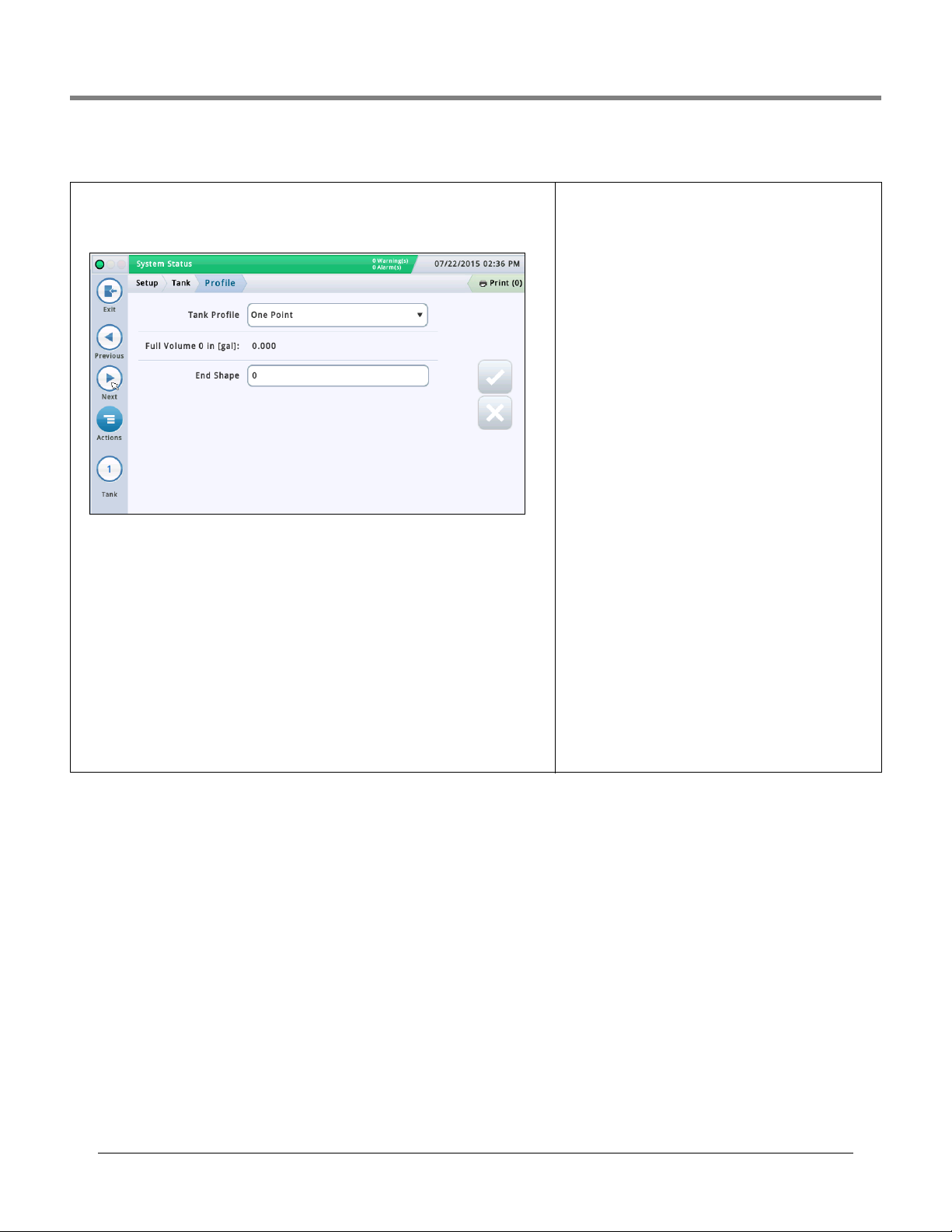
Initial Setup Of The Console Using Workflow Wizard Setup>Tank>Profile
Setup>Tank>Profile
Charts define how the console calculates the volume of fuel in each tank. A point in a chart
specifies a height value at a certain volume of fuel (chart data is stored for each monitored
tank). This information is critical for proper operation. This screen lets you manually setup a
tank chart using one of four tank profiles listed below.
You must have entered the diameter and full volume before selecting a tank chart (see
“Setup>Tank>General”).
Select a tank from the icon list on the bottom of the screen to configure.
Tank Profile
Touch to select a tank profile option:
One Point -This option uses only the 100% (full) volume to profile a tank.
This selection can be used for horizontally installed, flat-end cylindrical tanks, and when
AccuChart is available for this tank.
Four Point - This option requires 4 points to profile the tank. The requested volumes are at
percentages of height (e.g., the 75% volume of a 96" diameter tank equals the volume at a
height which is 75% of 96" or 72").
This selection can be used for all rounded- and dished-end tanks, and should be selected
when AccuChart is available for these type tanks.
Twe nty Poi nt - This option uses 20 Points to profile a tank.
The requested volumes are percentages of height (e.g., the
5% volume of a 96" diameter tank = the volume at a height
which is 5% of 96" or 4.8”).
This selection can be used for all rounded-end and dishedend tanks.
Linear - This option requires only the 100% (full) volume to
profile a tank.
NOTE: Instead of entering a diameter value in the diameter
field, enter a height value in the diameter field of the
“Setup>Tank>General” screen.
This profile can be used for flat-end cylindrical tanks standing on end, and for rectangular tanks.
Multi Point - This option is used for charts having more
than 20 points. See Setup > Tank > Multi Point for more infor-
mation.
Full Volume
[Read-only field] Total capacity and the diameter (full
height) of the tank.
This information can be handy when you are entering chart
information. The Full Volume value is entered in
“Setup>Tank>General”.
End Shape
[Field only available when you select One Point for Tank Profile field]
Enter a value from 0 to 1.0 in 0.1 increments (0.3 is the recommended value for dished-end tanks).
32
Page 37
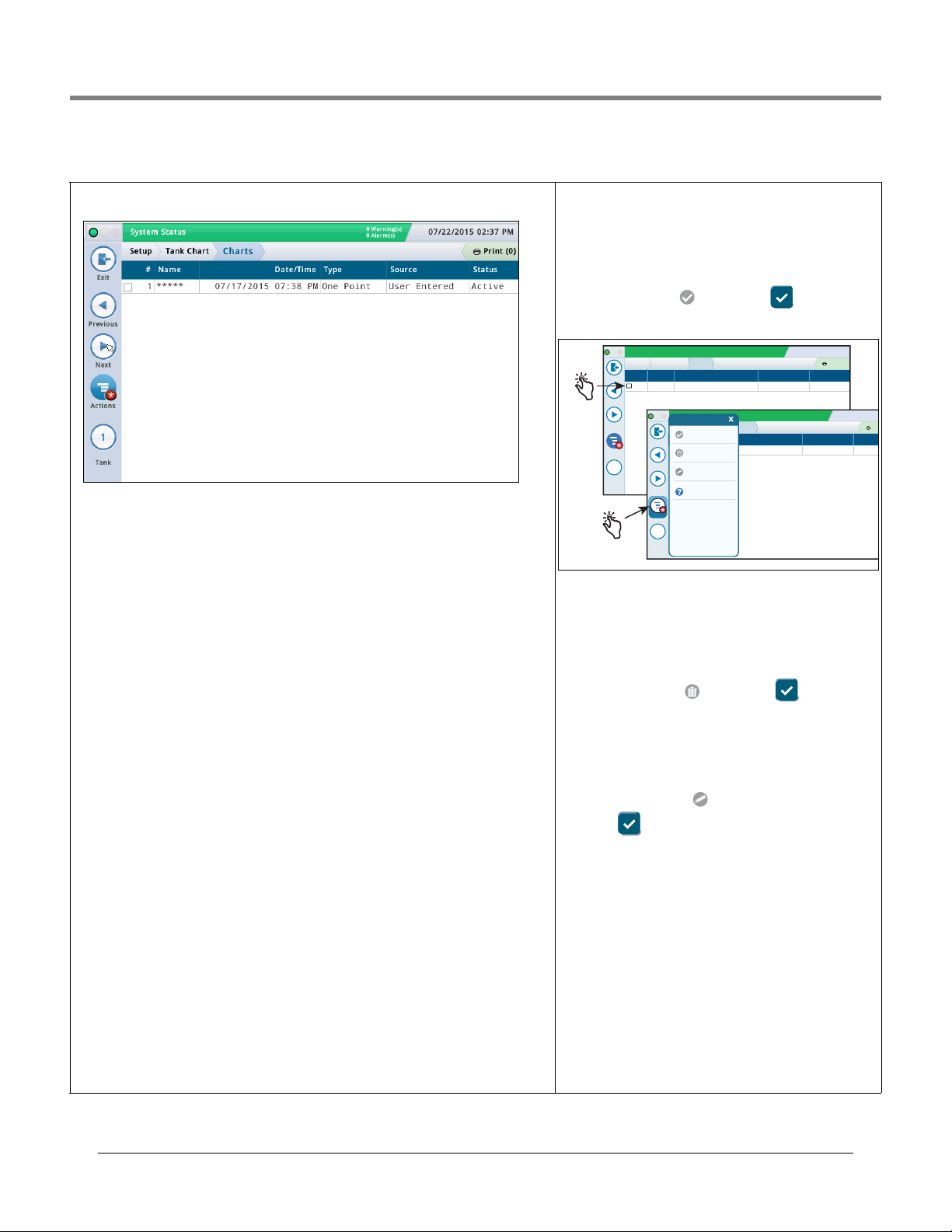
Initial Setup Of The Console Using Workflow Wizard Setup>Tank Chart>Charts
System Status
07/22/2015 09:18 AM
0 Warning(s)
0 Alarms(s)
Print (0)
Exit
Previous
Next
Actions
Tank
Setup
1 07 / 17 / 2015 07:38 PM User Entered Active
*****
Tank Charts Charts
# Name Date / Time Source Status
1
System Status
07/22/2015 09:18
0 Warning(s)
0 Alarms(s)
Pri
Exit
Previous
Next
Tank
Setup
1 07 / 17 / 2015 07:38 PM User Entered Active
*****
Tank Charts Charts
# Name Date / Time Source Status
1
Apply Chart
Actions
Delete Chart
Rename Chart
Help
Actions
Setup>Tank Chart>Charts
This screen provides information on the active and inactive charts for a tank, and lets you
select the chart you want to use for a tank (i.e., make a chart active for a tank).
Select a tank from the icon list on the bottom of the screen to view that tanks available
charts.
#
Number assigned by the console
Name
Name of chart. NOTE: If the chart is created by the console (for example, via AccuChart), the
name is automatically assigned
Date/Time
Date and time the chart was created.
Type
Chart type:
•One Point
•Four Point
•Twenty Point
•Multi Point
•Linear
See Setup > Tank > Profile for more information about chart types.
Source
How the chart was created:
Automatic - Using AccuChart
•
User-Entered - Using Setup >Tank Chart>Manual Calibration.
•
•
Meter Drop - Using Setup>Tank Chart >Manual Calibration. (Uses meters to measure fuel
volume; it does not require a full tank). Not available for siphon-manifolded tanks.
Meter Dispensed - Using Setup > Tank Chart > Manual Calibration. (Uses meters to mea-
•
sure fuel volume; it does require a full tank). Not available for line-manifolded or siphonmanifolded tanks.
Status
Current status of the chart:
•Active
• Ready
•Incomplete
•Bad Point
• Calculating
Making a Chart Active for a Tank
Select a tank from the icon list on the bottom of the screen to
view that tanks available chart(s).
Select a tank chart in the list by touching the check box next
to the chart number, then touch the Actions icon, to display
the Actions popup menu shown below.
Touch the Apply chart icon then the key to save
your entry.
Deleting a Chart
NOTE: You cannot delete the first (initial) chart for a tank.
Select a tank chart in the list by touching the check box next
to the chart number, then touch the Actions icon, to display
the Actions popup menu.
Touch the Delete Chart icon then the key to save
your entry.
Renaming A Chart
Select a tank chart in the list by touching the check box next
to the chart number, then touch the Actions icon, to display
the Actions popup menu.
Touch the Rename Chart icon, enter a new name, then
touch the key to save your entry
33
Page 38
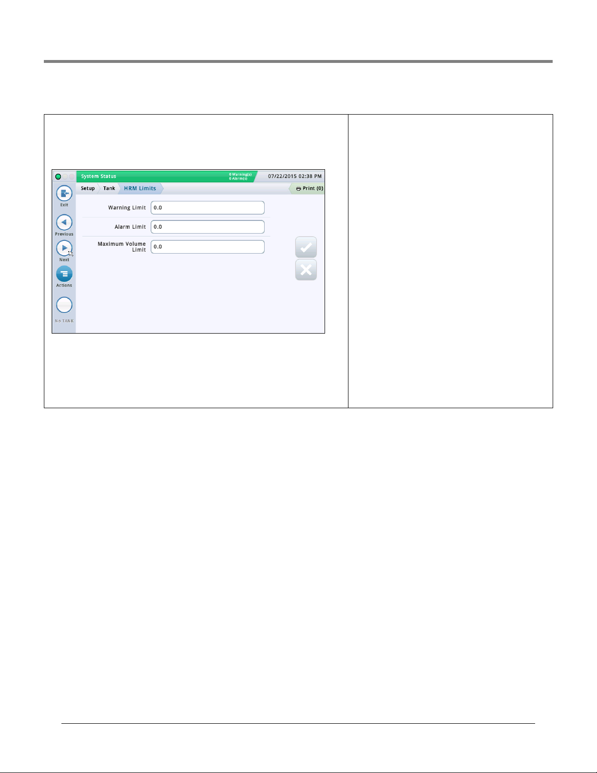
Initial Setup Of The Console Using Workflow Wizard Setup>Tank>HRM Limits (International Option)
Setup>Tank>HRM Limits (International Option)
When running the BIR program, the system has the capability to run in HRM mode, which
provides hourly reconciliation results. HRM is used in countries that use metric mode.
When a console is in HRM (Hourly Reconciliation Monitoring) mode, a tank Maximum Volume
Limit threshold is imposed. This screen lets you view and set three HRM volume threshold
alarms.
Warning Limit
An hourly limit in the variance in inventory, that when exceeded generates a warning.
The default warning limit is 3 litres. Min. value is 1 litre and max. value is 400 litres.
Alarm Limit
An hourly limit in the variance in inventory, that when exceeded generates an alarm. The
default warning limit is 4 litres. Min. value is 1 litre and max. value is 400 litres.
Maximum Volume Limit
An hourly volume limit in inventory, that when exceeded generates an alarm.
The minimum entry and default for this field is Tank Capacity
minus 500 litres. Since the user-entered Max. Volume (Label
Vol.) field in “Setup>Tank>Limits” screen is set to 100%
tank capacity, the HRM Maximum Volume Limit value entered
in this field will take precedence for Max Volume Alarm and
for computing ullage values.
The allowable range for this field is 500 to 999,999,999
litres.
Other notes: The default 500 liter limit is programmed as
132 gallons. In metric mode this gets displayed as 499.674.
Changing the US limit to 132.09 will display as 500 liters.
There is no need to display resolution lower than 1 liter.
34
Page 39
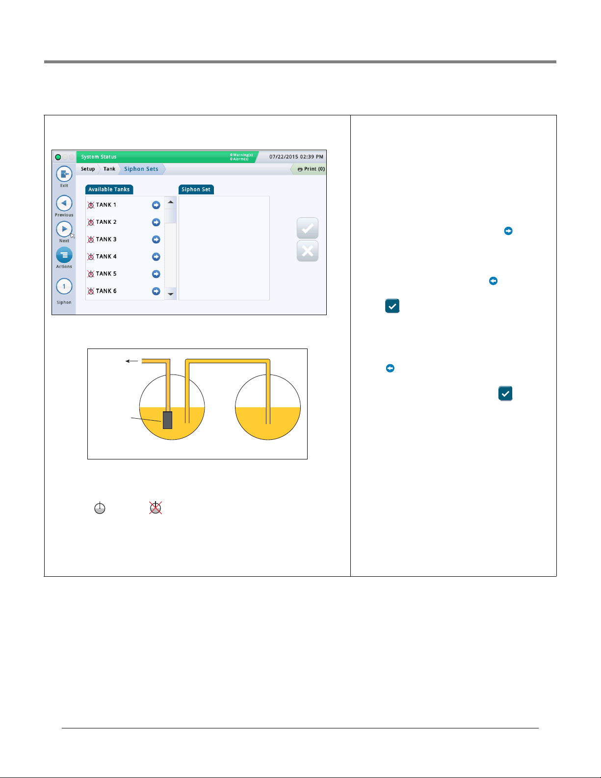
Initial Setup Of The Console Using Workflow Wizard Setup>Tank>Siphon Sets
Setup>Tank>Siphon Sets
This screen lets you define siphon manifolded sets, which are two or more tanks connected
by a manifold. Typically, with a 2” diameter manifold pipe and with the proper vacuum on the
line, a system can keep product flowing from one tank to another.
An example siphon set diagram is shown below:
Dispenser
STP
Secondary TankPrimary Tank
This setup allows roughly the same amount of product in both tanks. This application is typically used in large truck stops or high throughput tanks for unleaded fuel.
Available Tanks
Lists enabled and disabled tanks in your system.
Siphon Set
Tanks that make up the selected siphon set (if one is selected), separated by a semi-colon.
Viewing a Siphon Set
Select a siphon set from the icon list on the bottom of the screen. The tanks that make up
that siphon set are displayed in the Siphon Set column.
Creating a Siphon Set
Once a siphon set is created, the manifolded set icon
appears in tank displays like the Overview>Tank Overview
screen.
NOTE: The maximum number of siphon sets that can be con-
figured is the maximum number of tanks divided by 2,
rounded down.
1. Select the siphon set icon (bottom left of screen) and then
select a new siphon set number from the siphon set list that
displays along the bottom of the screen.
2. In the Available Tanks column, select the first tank you
want as part of this new siphon set and press . This
moves the tank to the Siphon Set column.
3. Repeat Step 2 for the next tank you need to add to your
siphon set. Continue to do this until all of the tanks you need
are moved into the Siphon Set column. If you need to move a
tank out of the Siphon Set column, select next to that
tank. That tank returns into the Available Tanks column.
4. Touch to save your settings.
Deleting a Siphon Set
1. Select a siphon set (from bottom left of screen). The tanks
that make up that siphon set are displayed in the Siphon Set
column.
2. Select next to each tank. This moves the tank out of the
Siphon Set column and back into the Available Tanks column.
3. Once you have moved out all tanks, touch to save
your settings.
Reporting When Using Siphon Sets
When using siphon manifold sets, the console will print mul-
tiple reports (one for each tank in the siphon set). To avoid
multiple reports, configure the print task using an eventbased trigger that references the first tank listed in the
siphon set. See Actions>Help>Understanding Automatic
Events for information about event-based triggers.
When you configure a print task using this method, the Last
Delivery Report includes a summation for all tanks in the
siphon set.
35
Page 40
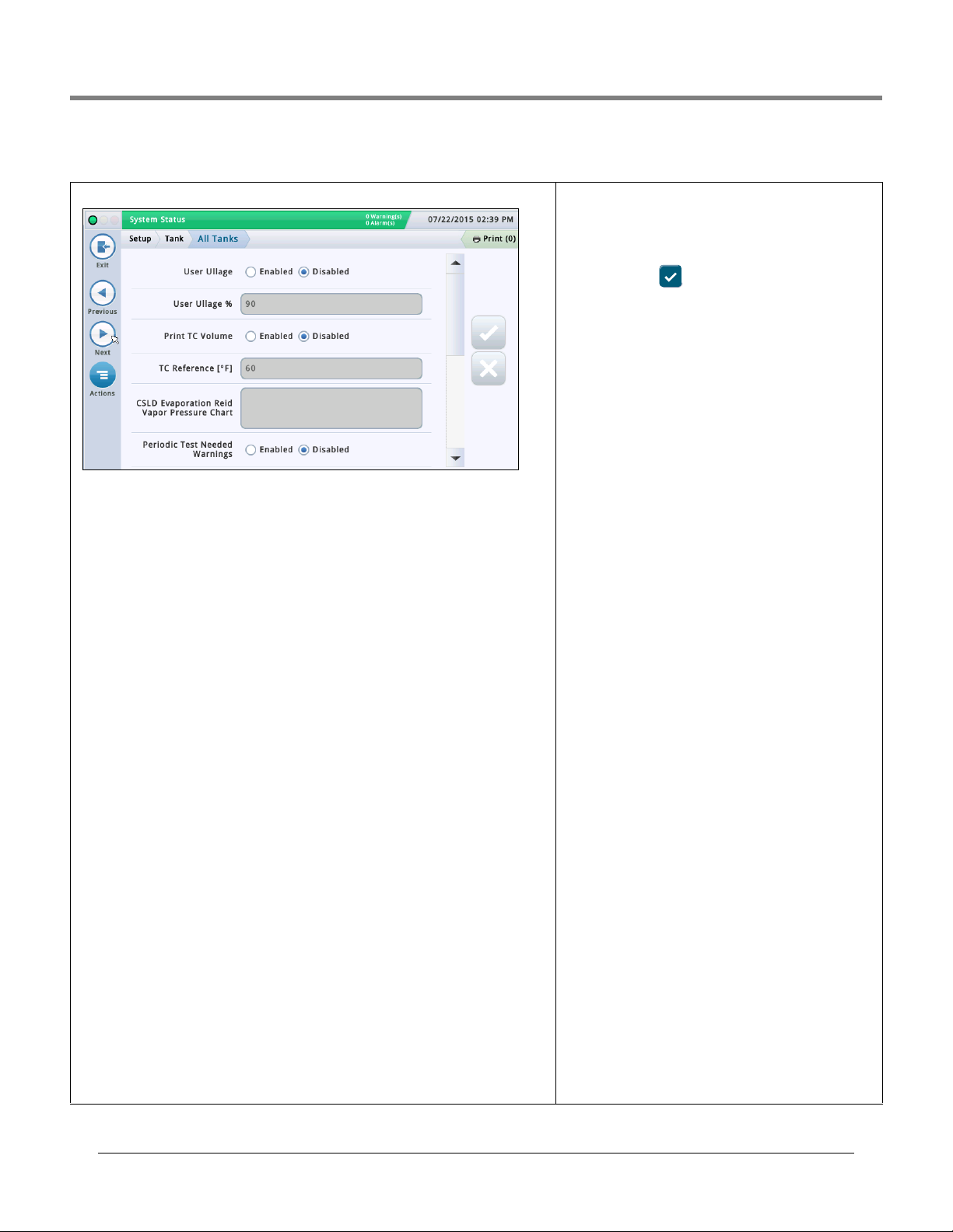
Initial Setup Of The Console Using Workflow Wizard Setup>Tank>All Tanks
Setup>Tank>All Tanks
This screen lets you configure parameters that apply across all tanks in the system.
User Ullage
Touch radio button to enable or disable the display of the User Ullage field (as can appear in
Overview>Tank Overview and Inventory Reports).
NOTE:
• The regular Ullage Volume field is displayed on most console screens, and is calculated by
taking the Max Volume field in the “Setup>Tank>Limits” screen and subtracting the volume of fuel currently in the tank. This result represents the total amount of empty space in
the tank.
• The User Ullage field is an additional informational field that calculates ullage using a percentage of the Ullage Volume field. User Ullage can be used as a cross-check for deliveries
to make sure you do not overfill a tank. In some regions, the ullage is set to between 50
and 100% of the tank (see field below). By setting the ullage to a lower percentage, it adds
an additional buffer so the tank will not be overfilled.
User Ullage%
[Field available only if User Ullage field is enabled]
Touch to enter a percent (from 50 to 100%) of ullage volume to display.
Print TC Volumes
Touch radio button to enable or disable the printing of temperature compensated (TC) volumes in screens or reports (inventory, delivery, etc.).
TC Reference
Temperature compensated (TC) reference temperature for all volume calculations, and is
location-specific. Some common values:
• U.S. 60°F • Canada 15°C
NOTES:
• All leak test calculations are based on the TC reference value that you enter in this field.
• If you do not enable the Print TC Volumes field above, TC values will not appear in the
screens.
• To use TC values, your probe must support temperature measurement capabilities.
• If BIR is being used and the meters reporting the sales are temperature compensated, the
value you enter must match the meters' reference temperature value. Also, in
“Setup>BIR>General”, the TC Reference field must be set to TC Volume.
CSLD Evaporation Reid Vapor Pressure Chart
This field, when enabled, lets you enter Reid Vapor Pressure (RVP) values used by CSLD.
Enabling RVP allows you to enter evaporation compensation values for each month for nondiesel tanks at the site.
This field is enabled if the following fields are set up in “Setup>Tank>Environmental Test”:
Tank Test Method is set to
pensation is set to Enabled.
CSLD, Climate Factor is set to Extreme and CSLD Evap. Com-
Entering Values for the CSLD Evaporation
RVP Chart
Once enabled (see above) and you select inside the RVP field
box, a popup window appears that lets you view or enter
RVP entries for each month of the year. Enter values for each
month field. touch to save your entries when done.
NOTE: CSLD evaporation compensation will use the RVP val-
ues from your entries for the applicable month. The console
does not provide evaporation compensation during months
having a RVP value of 0 (zero). The RVP monthly values for
your geographical area can be obtained from your local
Petroleum Distributor or is located on the delivery bill of lading.
Periodic Test Needed Warnings
Touch radio button to enable or disable the console to post a
warning or an alarm after a specified number of days have
passed (0 - 30 days) since the last 0.2 gph (0.76 lph) leak test
was run or successfully passed. The subsequent two fields
relate to this function:
Days Before Periodic Alarm
Post an alarm when the test did not successfully pass after a
warning, or if the test was not conducted in a specified num-
ber of days.
Days Before Periodic Warning
Post a warning when the test did not successfully pass, or if
the test was not conducted in a specified number of days.
Annual Test Needed Warnings
Touch radio button to enable or disable the console to post a
warning or an alarm after a specified number of days have
passed (0 - 365 days) since the last 0.1 gph (0.38 lph) leak
test was run or successfully passed. The subsequent two
fields relate to this function:
Days Before Annual Alarm
Post an alarm when the test did not successfully pass after a
warning, or if the test was not conducted in a specified num-
ber of days.
Days Before Annual Warning
Post a warning when the test did not successfully pass, or if
the test was not conducted in a specified number of days.
TC Density
Touch radio button to enable or disable TC density readings
for inventory reports.
NOTE: This should only be enabled if the site is equipped
with a Mag Plus Probe with a density float system.
Stick Height
Enables or disables the Stick Height fields that compensate
for any difference between a stick measurement and the
probe measurement (no tilt). The difference is due to the
stick and the probe measuring slightly different locations in
a tilted tank since the riser used for the stick measurement
is different than the riser used for the probe.
The stick height offset is set in “Setup>Tank>General”.
When enabled, the calculated stick heights are visible in
Tank Detail.
Stick height is not used for volume calculation; it is for display only.
36
Page 41
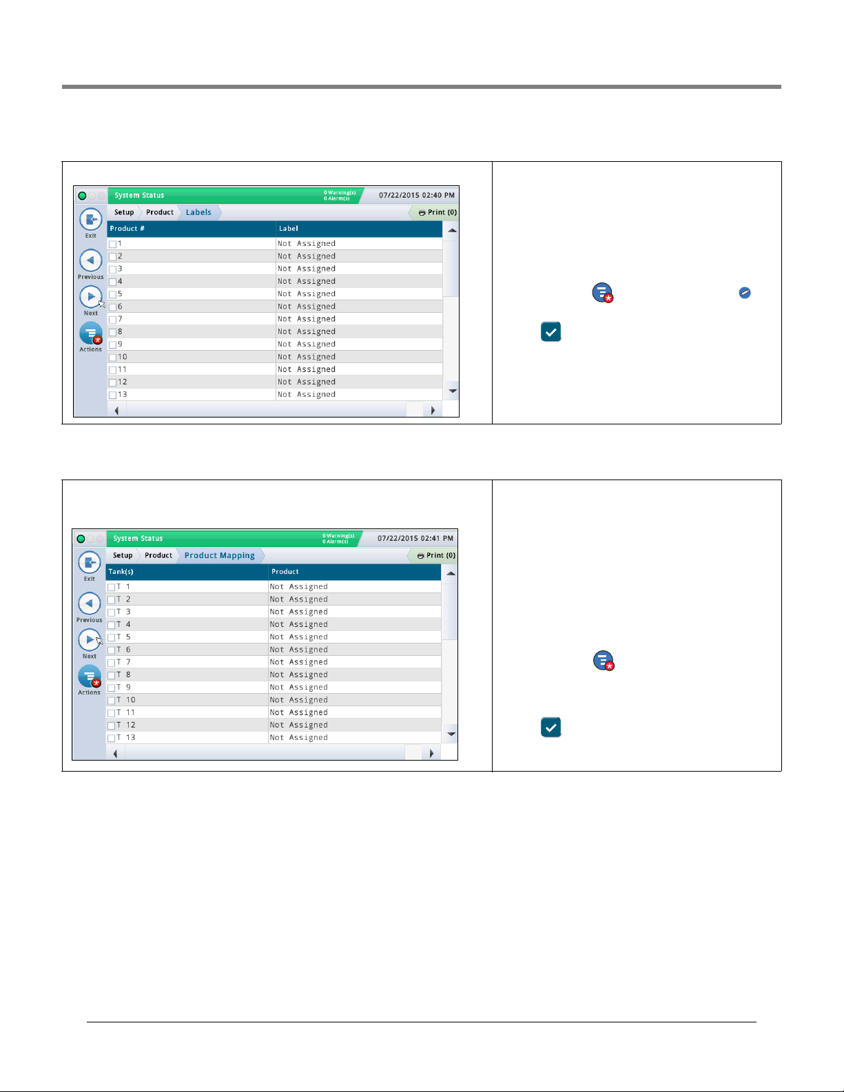
Initial Setup Of The Console Using Workflow Wizard Setup>Products>Labels
Setup>Products>Labels
This screen lets you setup tank product labels which are used in all BIR reports.
Setup>Product>Product Mapping
This screen lets you map a specific tank to a product. Depending on your site, you could have
two or more tanks with the same product. By properly mapping your tanks to the products,
you can group single and manifolded tanks into product-summarized BIR Reports.
Product #
This column lists the console assigned product number.
Product Label
This column lists the product label for the product number.
Editing A Label
1. Touch (highlight) a product number in the data view (a
checkmark appears in the box next to the number).
2. Touch the Actions icon and then the Edit Label icon
and enter a new label (up to 20 characters) for this product.
3. Touch to save your settings.
Tank(s)
This column lists the configured tank short device identifier/
number (for example, T1).
Product
This column lists the product number and the assigned product label (for example, "F1:Regular"). "Not Assigned" indicates the tank has not had a product mapped to it.
Editing Tank(s) Product Mapping
1. Touch (highlight) a tank in the data view (a checkmark
appears in the box next to the tank’s device identifier/num-
ber).
37
2. Touch the Actions icon and then select Edit Tank(s)
Product.
1. From the pull down menu select the product you want to
map to this tank.
3. Touch to save your settings.
Page 42

Initial Setup Of The Console Using Workflow Wizard Setup>Tank Chart>AccuChart
Setup>Tank Chart>AccuChart
This screen lets you setup the AccuChart automatic calibration feature for a tank.
Make sure the following is done before you start an AccuChart calibration:
• The tank has a chart created in Tank Profile which will be used in the AccuChart calibration.
• The dispenser meters are calibrated so the system has accurate dispense measurements
to use in the AccuChart calibration process.
Select any tank from the icon list on the bottom of the screen to enter its AccuChart settings.
Update Schedule Describes how AccuChart calibration charts are updated and assigned to tanks Method:
Immediate
the chart immediately becomes active, the console calculation of product volume will also
change based on the data in the newly active chart.
Charts may be created multiple times during the calibration period, so the calculated product
volume may also change multiple times.
If you enable AccuChart warnings, the console will post warnings if charts have not been
generated during the calibration period.
Periodic - Select up to four target dates on which the console will activate a generated
chart. If a chart is available on one of the target dates, the console activates the chart. You
can view available charts in “Setup>Tank Chart>Charts”.
If there are multiple charts available, the console will activate the chart with the best data
sufficiency. See the Actions>Help>Diagnostic>AccuChart>Data Sufficiency topic for more
information.
If you enable AccuChart warnings, the console will post alarms if the console has not generated any charts during the calibration period. On the final target date the console will also
post a warning if there are no new charts available for this tank.
Complete
becomes the active chart. Data Sufficiency is not considered; only the date the chart was
created.
If you enable AccuChart warnings, the console will post warnings if charts have not been
generated during the calibration period.
Never - The console never automatically makes an AccuChart-generated chart the active
chart for this tank.
- The active chart is updated every time AccuChart generates a chart. Because
- The last chart generated by AccuChart at the end of the calibration period
Apply Date 1 - Date 4 Fields
[Field available only if the Update Schedule field is set to Period]
Touch to enter four target dates for periodic generation of an active chart by the console.
The recommended periodic selection period is 14 days apart (for example, 14, 28, 42 and
56).
Calibration Period
Touch to enter the number of days to calibrate the tank (typically 30 - 120 days).
The calibration period depends on tank activity. A lowthroughput tank (e.g., one that has a "high test" fuel) may
require a longer calibration period than a quick-throughput
tank (e.g., one that has "regular" fuel).
: If, at one day prior to the end of your calibration
NOTE
period selection, AccuChart has insufficient data to create a
tank chart, it posts a warning (if the Enable AccuChart Warnings field below is set to Enabled), allowing you the opportunity to extend the calibration period.
Days Left to Calibration Completion
[Read-only field] The number of days remaining to complete
the calibration (after you initiate a calibration using the Start
button), including the start date of the calibration.
Exclude Days
Touch to remove specific days from the calibration period.
For example, you may want to exclude the days the site had
maintenance performed, such as when meter calibration
occurs.
: If you need to exclude more than 25% of the calibra-
NOTE
tion period, we recommend you stop the tank calibration.
Delete any created charts and restart the calibration.
Enable AccuChart Warnings
Touch to enable or disable AccuChart warnings. When
enabled, the system produces a warning when AccuChart
has not completed a calibration because of insufficient data.
See Diagnostic>AccuChart>Calibration Feedback for more
information.
Min Operating Level%
Touch to enter the desired minimum operating height of the
fuel (as percentage of tank diameter) for valid calibration
results. It should be greater than or equal to 10%. The
default is 10%.
Max Operating Level%
Touch to enter the desired maximum operating height of the
fuel (as percentage of tank diameter) for valid calibration
results. It should be less than or equal to 95%. The default is
95%.
NOTE: The difference between the Min Operating Level% and
the Max Operating Level% should be at least 50% and should
include the midpoint of the tank (50%). The 50% setting cannot be the endpoint of the range between the Min and Max
Operating Level%. For example, you can enter a range of
25% to 85%, but you cannot enter a range of 5% to 50%.
Start
Touch Actions then the Start on the Actions popup
menu. If you select at the prompt to start the calibration, a
new AccuChart calibration is started and the following is
done:
• Sets the Start of Calibration field to the current date.
• Sets the Days Left To Calibration Completion field to the
number of days in the calibration period. This field displays
in the Diagnostic > AccuChart > Data Sufficiency screen.
• Clears all AccuChart alarms and warnings.
38
Page 43

Initial Setup Of The Console Using Workflow Wizard Setup>Tank Chart>AccuChart
Setup>Tank Chart>AccuChart - Concluded
Stop
Touch Actions then the Stop on the Actions popup menu. If you
select at the prompt to stop the calibration, the AccuChart calibration stops.
Notes When Working with AccuChart:
If the console is powered down during one of the Immediate or Periodic
updates, or if a time/date change is made at this time, the update will be
missed. If this occurs during the final Periodic update, or at the end of the
calibration period for Immediate and Complete update selections, the calibration will be attempted at the next date change. The update will be done
with this calibration, or the last generated calibration, or AccuChart will
generate warnings.
• If you enter the Start Date values in a random order, the system will rearrange them in increasing order (after screen is refreshed). Empty Apply
Date 1 through 4 fields will be grouped at the bottom of the set. This may
cause the entered values to move around.
• If the calibration is in progress and the console clock is set back before
the start of calibration, the start of calibration will be moved back to the
new time, and the 'Update Schedule' dates will all be adjusted appropri-
ately (including Periodic).
39
Page 44

Initial Setup Of The Console Using Workflow Wizard Setup>Pumps and Lines>Pumps
Setup>Pumps and Lines>Pumps
This screen lets you configure the site's pumps that will be monitored by the console.
Select a pump from the icon list on the bottom of the screen to configure.
Configured
Touch the radio button to enable or disable the selected pump.
NOTE: Set to Enabled only after completing all of the settings for this pump.
Pump Label
Touch to enter a description for this pump.
Mode
Touch to determine how the pump is controlled:
• TLS Pump Control - Pump is controlled or actuated locally by the console.
Pump Sense - A pump request signal is sent to the console to turn on/off the pump (this
•
signal also acts as a tank "active" signal to the console).
• External Pump Control - Pump is controlled externally to the console and identifies
tanks that are line manifolded together.
Tank
Touch to assigned the tank assigned to the selected pump. NOTE: There may be both configured and non-configured items on this field's drop-down list (non-configured items will be
prefixed by a "!).
Pump Control
[Field only enabled when the Mode field is set to "TLS Pump Control"].
A device that responds to dispense requests and actuates the selected pump. These devices
are normally relays that have been configured and assigned as pump controlling devices in
Setup>Devices (“RELAY SETUP”).
Pump control relay assignments are usually unique for each pump. A warning dialog will display if the pump control selected is already assigned to another pump (this alert is not an
alarm or error since some sites use a single pump control output for more than one pump).
NOTE: There may be both configured and non-configured items on this field's drop-down list
(non-configured items will be prefixed by a
"!).
Pump Sense
[Field only enabled when the Mode field is set to "TLS
Pump Control
The external input that tells the console when the pump is on
or off. Pump sense inputs are configured and assigned in
Setup > Devices (“EXTERNAL INPUT SETUP”). More than
one pump may use the same pump sense input.
NOTE: There may be both configured and non-configured
items on this field's drop-down list (non-configured items will
be prefixed by a ‘!’).
" or "Pump Sense"].
Line
[Read-only field]. The line identifier of the selected pump
(shows "Not Assigned" if that is the case).
Pump Relay Monitor Device
[Available with PLLD]. The external input that generates a
pump relay alarm when the console suspects a relay is stuck
or when the pump has been running continuously for a
period exceeding the Max Run. The device is configured and
assigned in Setup>Devices (“EXTERNAL INPUT SETUP”).
Stuck Relay
[Available with PLLD]. The console suspects a pump relay is
"stuck" when the pump relay signal is inactive but the pump
monitor indicates the pump is powered. When a pump relay
fault detected by the console has persisted beyond this
delay, a Pump Relay Alarm is generated. Touch to enter a
Stuck Relay delay time from 5 to 600 seconds. The default is
60 seconds.
Max Run Time
[Available with PLLD]. When the console detects that a
pump has running continuously for longer than the time
entered in this field. Touch to enter time from 1 to 24 hours.
40
Page 45

Initial Setup Of The Console Using Workflow Wizard Setup>Pumps and Lines>Line
Setup>Pumps and Lines>Line
This screen lets you configure line leak monitoring of individual product lines (TLS-450PLUS
consoles only).
Select a line from the icon list on the bottom of the screen to configure.
Configured
Touch the radio button to enable or disable the selected line.
NOTE: Set to Enabled only after completing all of the settings for this line.
Line Label
Touch to enter a description for this line.
Leak Monitoring
Touch to enable or disable PLLD monitoring on this line.
Pressure Sensor
Touch to select the line pressure sensor assigned to this line, (see ‘Setup>Devices - “LINE
PRESSURE SENSOR SETUP”).
Line Manifolded
Touch Yes if line is manifolded, No if not.
Dispense Mode
[Only enabled if Line Manifolded field is set to "Yes"] - Touch to select the dispense mode
for this line.
• Standard - Only one pump feeds the line.
•
Manifolded Alternate - Volume
tank with the greatest inventory volume and switches to an alternate tank based on the
Active Switchover and Threshold settings below.
1,2
- For line manifolded tanks, the console chooses the
• Manifolded Sequential
with a pump on the line, tanks are pumped one at a time until
the volume drops below the Pump Threshold (%) value set in
the Setup > Tank > General screen. At that point, pumping
will commence on the next available tank in the line set.
1,2
- If there is more than one tank
• Manifolded: All Pumps- All pumps on the line are run.
• Manifolded: Pump Sense - Pump Sense information is
available for the pumps on this line. This can be used to
improve CSLD performance.
Manifolded: Alternate Height - For line manifolded
•
tanks, the console chooses the tank with the greatest
height and switches to an alternate tank based on the
Active Switchover and Threshold settings below.
Active Switchover
This field is active if either Alternate Volume or Alternate
Height is selected in the Dispense Mode field above. Choices
are:
• Yes - Enables the switchover to an alternate tank, based
on which tank has the greatest volume/height, taking into
account the threshold value below
• No - Disables the switchover to an alternate tank. This is
the default.
Switchover Volume Threshold
The volume used to determine when to switch over to an
alternate tank. The console switches to an alternate tank
(without losing line pressure) when the difference is greater
than this threshold. The field can be set to a value between
10 and 999 gallons (37.8 - 3781.6 litres). The default value is
200 gallons (757 litres).
Switchover Height Threshold
The height used to determine when to switch over to an
alternate tank. The console switches to an alternate tank
(without losing line pressure) when the difference is greater
than this threshold. The field can be set to a value between 1
and 99 inches (25.4 - 2514.6 mm). The default value is 2
inches (50.8 mm).
Pumps
Touch to select a pump to assign to the line. If the Line Manifolded field above is set to Yes, you can select multiple
pumps for this line.
1. To prevent backfilling, the level of all tanks connected to the line will be monitored. If the level of any tank exceeds 95% of the Max or Label Volume
limit (see “Setup>Tank>Limits” on page 28), the pump for that tank will also be turned on during dispensing. The state of the pump that was
already ON will not be changed.
2. At locations with manifolded fuel lines that have a mechanical line leak detector installed for each pump, the TLS Console must be programmed
for either Alternate or Sequential. Doing so ensures that each line meets the 3 GPH requirement.
41
Page 46

Initial Setup Of The Console Using Workflow Wizard Setup>Pumps and Lines>PLLD
Setup>Pumps and Lines>PLLD
This screen lets you setup parameters for individual lines when Pressurized Line Leak Detection (PLLD) is enabled. Also, if Leak Monitoring is not enabled (in “Setup>Pumps and
Lines>Line”) for at least one line, then none of the PLLD screens can be edited.
The maximum number of lines that can be configured for Leak Detection is equal to the maximum number of STPs as determined by your console. However, only those lines for which
Leak Monitoring is enabled (in “Setup>Pumps and Lines>Line”) are shown.
Automatic dialing or sending of PLLD alarms is setup in Automatic Events setup (Setup>
Automatic Events).
Select a line from the icon list on the bottom of the screen to configure.
Configured
Touch the radio button to enable or disable the PLLD feature for the selected line.
NOTE: In setup wizard, you should enable settings as you go.
Controlling Pump
Touch to enter pump controlling this tank. Note: Pump must be programmed to use Pump
Control (see “Setup>Pumps and Lines>PLLD” on page 42).
Pipe Type
Touch to enter the pipe type for this line. Refer to the ‘Supported Pipe Types and Line Lengths’
table in the Veeder-Root Electronic Line Leak Detectors Application Guide (P/N 577013-465).
NOTE: The fields that display below are dependent on, and applicable to, the Pipe Type
selected. For example, if you select 2/3 IN. FIBERGLASS, the applicable fields that display
will allow you to enter lengths for the 2" diameter and the 3" diameter pipe. If you select
"user defined" pipe type, fields for setting up the 1st and 2nd line diameters, line lengths,
and bulk modulus will display.
Line Length
The length of the piping between the tank and the dispensers, including the length between
the check valve and where it connects into the product line. Line lengths are whole numbers.
Values are in foot or meter increments, depending on system units.
Allowable selections:
Veeder-Root Electronic Line Leak Detectors Application Guide (P/N 577013-465).
The default is 0 but leaving it at 0 after entering a line length will cause a data setup warning.
Refer to the ‘Supported Pipe Types and Line Lengths’ table in the
Line Diameter
Allowable selections: 0 to 3.00 in (0 to 76.20mm)
The default is 0 but leaving it at 0 after entering a line length
will cause a data setup warning.
2nd Line Length
Allowable selections: Refer to the ‘Supported Pipe Types and
Line Lengths’ table in the Veeder-Root Electronic Line Leak
Detectors Application Guide (P/N 577013-465).
Default: 0
2nd Line Diameter
Allowable selections: 0 to 3.00 in (0 to 76.20mm)
The default is 0 but leaving it at 0 after entering a line length
will cause a data setup warning.
1st Line Bulk Modulus
[only available if the pipe type is user-defined]
The line's resistance to uniform compression.
Refer to the ‘Supported Pipe Types and Line Lengths’ table in
the Veeder-Root Electronic Line Leak Detectors Application
Guide (P/N 577013-465).
Allowable selections: 1000 to 200,000 psi (6892 to
1,378,359kPa).
The default is 0 but leaving it at 0 after entering a line length
will cause a data setup warning.
2nd Line Bulk Modulus
[only available if the pipe type is user-defined]
The line's resistance to uniform compression.
Refer to the ‘Supported Pipe Types and Line Lengths’ table in
the Veeder-Root Electronic Line Leak Detectors Application
Guide (P/N 577013-465).
Allowable selections: 1000 to 200,000 psi (6892 to
1,378,359kPa)
The default is 0 but leaving it at 0 after entering a line length
will cause a data setup warning.
Thermal Coefficient
If the controlling pump assigned to the line has a tank
assignment, this field is set to the thermal coefficient from
that tank (see “Setup>Tank>General”) and the field is
read-only. If there is no tank assignment, you can edit this
field. If the tank assignment is removed, the system will use
the default thermal coefficient 0.00070 U.S. Units (0.00126
Metric Units).
Allowable selections: 0.0 to 0.0016 gal./gal./°F (0.0 to
0.00288 lit./lit./°C)
42
Page 47

Initial Setup Of The Console Using Workflow Wizard Setup>Pumps and Lines>PLLD
Setup>Pumps and Lines>PLLD
0.2 gph (0.76lph) Line Leak Test
Touch to select the scheduling frequency of the 0.2 gph (0.76lph) periodic
tests:
Disabled - No manual, repetitive, or monthly 0.2 gph (0.76lph) testing is
allowed. This is the default.
Repetitive - After a dispense, a 3.0 gph (11.3lph) test is run, followed by a
0.2 gph (0.76lph) test. The test blockout period (the Precision Test Delay
in “Setup>Pumps and Lines>All PLLD”) is then observed. Following the
test blockout period, the test sequence repeats after the next dispense.
NOTE: If the 0.1 gph (0.3 lph) test is set for
be set to Repetitive. This selection also enables manual 0.2 gph (0.76lph)
tests to run when manually started.
Monthly - The test is scheduled at the beginning of a new month and
remains scheduled until a test is passed.
Manual - 0.2 gph (0.76lph) tests run only when manually started in Diagnos-
tics>PLLD>Manual Tests
Repetitive, this test must also
0.1 gph (0.38lph) Line Leak Test
Touch to select the scheduling frequency of the 0.1 gph (0.38lph) precision
tests.
Disabled - No manual or automatic 0.1 gph (0.3 lph) testing is allowed. This
is the default.
Repetitive - After a dispense, a 3.0 gph (11.3lph) test is run, a 0.2 gph
(0.76lph) test is run, followed by the 0.1 gph (0.38lph) test. The test blockout
period (the Precision Test Delay in “Setup>Pumps and Lines>All PLLD”)
is then observed. Following the test blockout period, the test sequence
repeats after the next dispense. This selection also enables manual 0.1 gph
(0.38lph) testing tests to run when manually started.
Auto - The 0.1 gph (0.38lph) test is automatically scheduled ro tun 6 months
after the last passed 0.1 gph (0.38lph) test. This setting also gives you the
option to run the Passive 0.1 gph (0.38lph) Line Leak Test.
Manual - 0.1 gph (0.38lph) test runs only when manually started in Diagnos-
tics>PLLD>Manual Tests.
Passive 0.1 gph (0.38lph) Line Leak Test
[only available if the pipe type is user-defined and the 0.1 gph (0.38lph) Line
Leak Test is set to Auto].
Enables a 0.1 gph (0.38lph) test to run after a passed 0.2 gph (0.76lph) test
without the 0.1 gph (0.38lph) test being actively scheduled. If the 0.1 gph
(0.38lph) test also passes, you are notified in Diagnostics>PLLD> 0.1 GPH
Tests. If it fails, there is no notification of the passive 0.1 gph (0.38lph) test.
Allowable selections: Yes, No (default is No).
Shutdown Rate
The line is shut down if a specified or less precise PLLD test fails. For exam-
ple, if you set the shutdown rate for 0.2 gph (0.76lph), the line will shut down
if it fails both the 3.0 gph (11.3lph) test and the 0.2 gph (0.76lph) test.
Allowable selections: 3.0 gph (11.3lph), 0.2 gph (0.76lph), 0.1gph (0.38lph),
or None (default is 3.0 gph (11.3lph).
Low Pressure Shutoff
If a low pressure is detected during dispense, the Low Pressure Alarm is
triggered. The dispenser also halts dispensing if this field is enabled and the
pressure is less than the
Allowable selections: Disabled, Enabled (default is Disabled).
Low Pressure Shutoff Value field below.
Low Pressure Shutoff Value
If a low pressure is detected during dispense, a low pressure alarm is triggered. The dispenser also halts dispensing if the pressure is lower than the
value in this field.
Allowable selections: 0 to 25 psi (0 to 172kPa)
Default: 0.0
Continuous Handle Timeout
If the dispenser handle remains off the hook for the period of time entered in
this field, the line is shut down by the console.
Allowable selections: 1 to 16 hours. Default: 16 hours
Fuel Out Limit
If the tank product level is below the limit entered in this field, the Fuel Out
Alarm is triggered.
Allowable selections: 0.00 to 15.00 in (0.00 to 381.00mm). Default: 10.00 in
(254mm).
Altitude Pressure Offset
Allows you to set an altitude pressure adjustment for the absolute pressure
transducer of plus or minus 5psi.
Allowable selections: -5.0 to 5.0. Default: 0.0.
43
Page 48
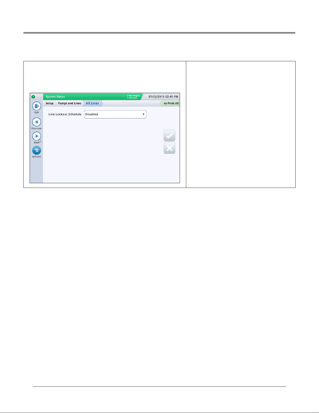
Initial Setup Of The Console Using Workflow Wizard Setup>Pumps and Lines>All Lines
Setup>Pumps and Lines>All Lines
This screen lets you setup a line lockout schedule to prevent PLLD testing when you know
that the pump will be powered off. In some areas, regulations prohibit leaving power to submersible pumps switched on during hours when the site is unattended. You should lock out
the lines during these hours.
Line Lockout Schedule
Touch to select a schedule for lockout events:
Disabled - No lockout events scheduled
Daily - Allows for one lockout event per day
Individual - Allows for up to seven lockout events per
week
Day of Week
Touch to select the day of the week for the lockout event.
Only available if the individual lockout schedule was
selected above.
Start Time
Touch to select the start time for the lockout event.
End Time
Touch to select the end time for the lockout event.
44
Page 49
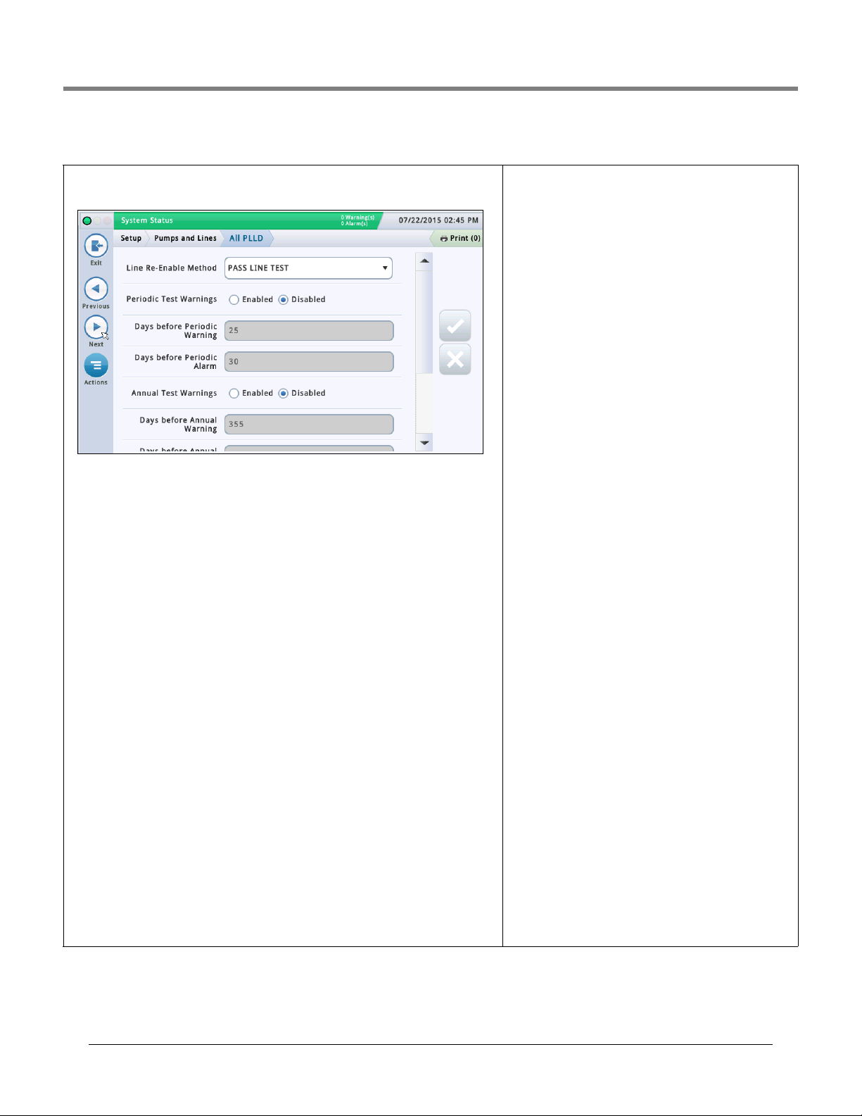
Initial Setup Of The Console Using Workflow Wizard Setup>Pumps and Lines>All PLLD
Setup>Pumps and Lines>All PLLD
This screen lets you setup test parameters for all pressurized line leak detectors.
Line Re-Enable Method
Determines what conditions allow you to re-enable the line.
Allowable selections:
• Pass Line Test - The line must pass the test in order to be enabled.
•Alarm Acknowledge - The line can be enabled after the alarm is acknowledged.
Periodic Test Warnings
Touch to enable or disable the Periodic Test Needed Warning/Alarm which informs you that
a line will soon be out of compliance because a Periodic test was not completed within the
required time. This lets you stop dispensing from the line until a Periodic test has been com-
pleted.
Days before Periodic Warning
The number of days before the Periodic Test Alarm Warning is triggered.
Allowable selection: 0 - 30 days (default is 25 days).
Days before Periodic Alarm
The number of days before the Periodic Test Needed Alarm is triggered.
Allowable selection: 0 - 30 days (default is 30 days).
Annual Test Needed Warnings
Touch to enable or disable the Annual Test Needed Warnings which informs you that a line
will soon be out of compliance because an Annual test was not completed within the
required time. This lets you stop dispensing from the line until an Annual test is completed.
Days before Annual Warning
The number of days before the Annual Test Needed Warning is triggered.
Allowable selection: 0 - 365 days (default is 355).
Days before Annual Alarm
The number of days before the Annual Test Needed Alarm is triggered.
Allowable selection: 0 - 365 days (default is 365)
Precision Test Delay (hours)
The number of hours between a passed periodic or annual
test and running the next line test(s).
NOTE: In previous TLS consoles, this was referred to as Precision Test Duration.
Allowable selection: 12 to 744 hours
NOTE: When CSLD is enabled for the tank assigned to the
line, a minimum value of 60 hours is used internally when the
precision test delay value is less than 60.
0.1 gph (0.38 lph) Line Test Auto Confirm
Touch to enable or disable the ability of the console to evaluate several 0.1 gph (0.38 lph) line tests before a result is
posted. Enabling Auto Confirm reduces the risk of false test
results, but it extends the time that it may take to post
results.
0.2 gph (0.76 lph) Line Test Auto Confirm
Touch to enable or disable the ability of the console to evaluate several 0.2 gph (0.76 lph) line tests before a result is
posted. Enabling Auto Confirm reduces the risk of false test
results, but it extends the time that it may take to post
results.
See the Actions>Help>Understanding Regulatory Compli-
ance In-Tank Leak Tests topic for more information.
45
Page 50
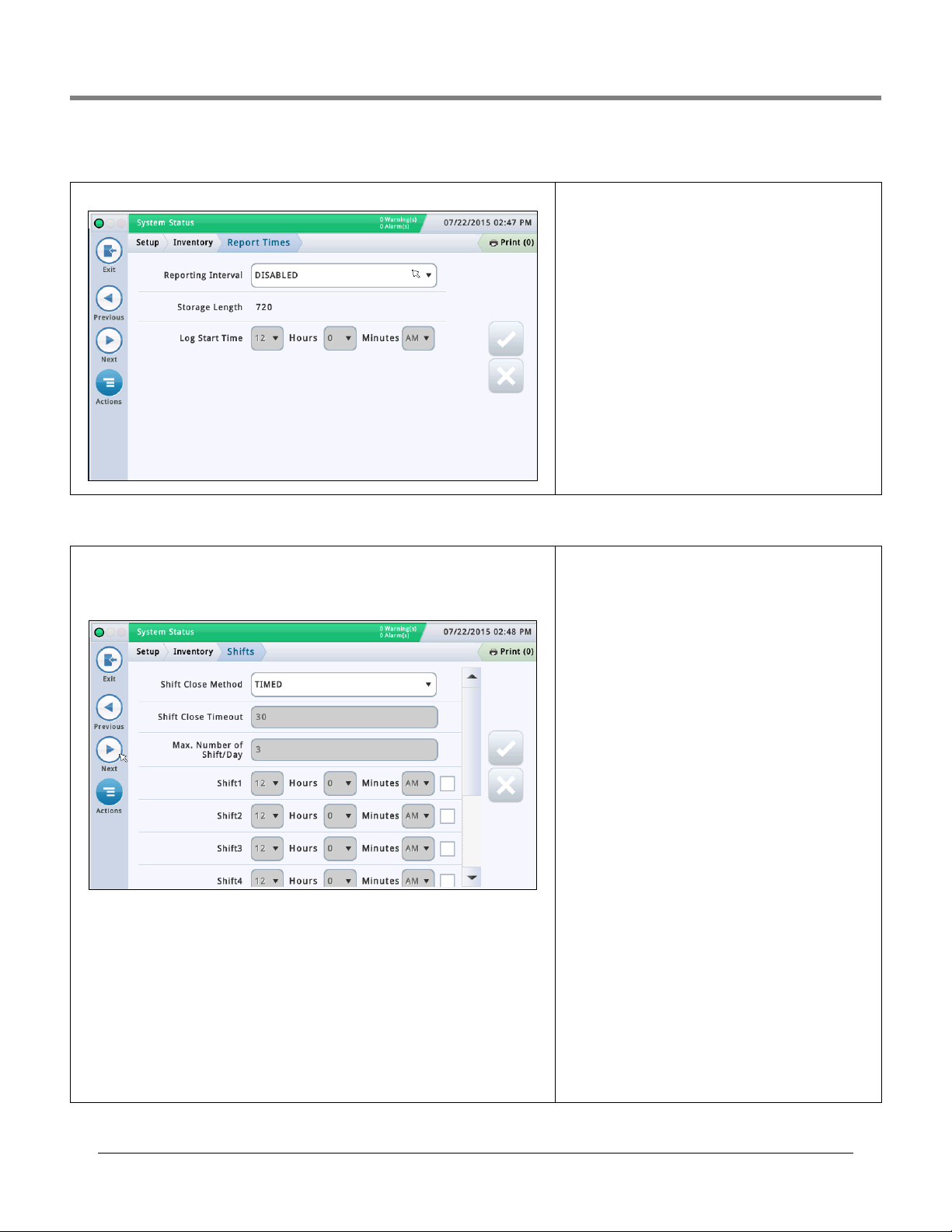
Initial Setup Of The Console Using Workflow Wizard Setup>Inventory>Report Times
Setup>Inventory>Report Times
This screen lets you set up how often Inventory History reports are generated.
Setup>Inventory>Shifts
This screen lets you setup the shift schedule and the shift close method. Shifts are used as
planning time periods for activities like reconciliation and BIR reporting.
If shifts are enabled, a new shift inventory report will be created and will include the shift
number. You can also access current or historical reports of shifts.
Shift Close Method
Timed
• The console will start and stop shifts automatically without any user action.
• You need to enter at least one shift time field (see Shift Times field below).
• When set to timed, a manual shift close will close the shift for ALL tanks, but the tank(s)
must be idle before a shift can close. Once a timed shift has been closed, no other shift can
be closed until the shift duration ends.
Manual
• You close a shift directly on the console by going to Actions > Close Shift. Each time you
close a shift directly, the console considers the current shift over, and the next shift has
started.
Reporting Interval
Touch to select how often reports are generated (choices
are):
Disabled, 5 minutes, 10 minutes, 15 minutes, 20 minutes, 30
minutes, 1 hour (default), 2 hours, 3 hours, 4 hours, 6 hours,
8 hours, 12 hours or 24 hours.
Storage Length
[Read only field] This is the maximum number of records
that can be stored by the system.
NOTE: When you the system reaches 721 records, the oldest
records will start to drop off the report.
Log Start Time
[If reporting interval is set to two hours or more]
touch to select time to start logging.
•You must wait a minimum of two hours between the close
of each manual shift. If you try to close a shift sooner, a
warning message displays.
•BIR manual shift close can be applied to all tanks or to an
individual tank. The BIR tank will immediately close when
the operator makes the request. There is no waiting or
idle time. The remaining open tanks must be closed within
the shift close timeout period (see Shift Close Timeout
field below). Tanks opened after the shift close timeout
period will be automatically closed.
Shift Close Timeout
[For "Manual" shift close method only].
Touch to enter the shift Close Timeout period (30 to 60 min-
utes)
NOTES:
• When you close a shift, you can select an individual tank to
close. The console will close the selected tank, but wait for
the amount of time as specified in this field, and then close
the shift for all remaining tanks.
• This feature makes it possible to complete a delivery for a
tank before closing the shift.
Max. Number of Shift/Day
[For "Manual" shift close method only]
Touch to enter the maximum number of shifts per day, up to
8 (default is 3)
Shift Times (1 - 8)
[For "Timed" shift close method only]
Touch to enter the starting time for each shift.
46
Page 51
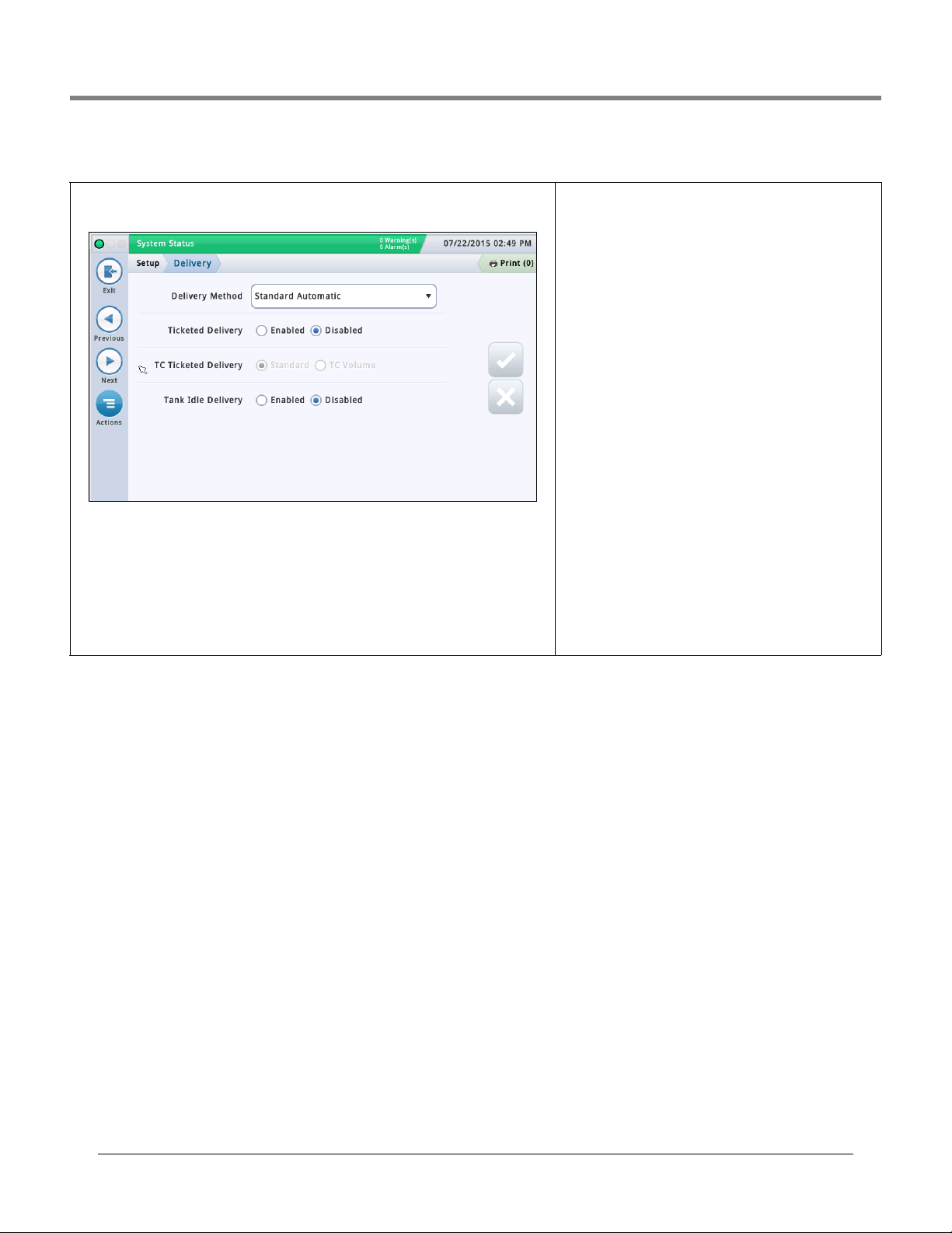
Initial Setup Of The Console Using Workflow Wizard Setup>Delivery
Setup>Delivery
This screen lets you configure the delivery method.
Delivery Method
Touch to select the type of delivery method for receiving inventory. Choices are:
Standard Automatic - The console detects that a delivery is taking place when there is
an increase in fuel height as measured by the probe. A delivery is complete when the height
no longer increases (default option that works in most applications).
Manual - You manually indicate that a delivery is taking place using the Start and Stop but-
tons. See the Reports>Delivery>Manual Delivery screen for information about how to perform a Manual Delivery.
Ticketed Delivery
If you enable ticketed delivery, you can manually enter ticketed volumes using the receipts from delivery trucks.
Enabling this feature generates reports showing delivery
variances between ticketed volume and gauged volume and
book variance.
TC Ticketed Delivery
[Available only if you Enabled Ticketed Delivery]
Touch to select the type of ticketed delivery. Choices are:
Standard, TC Volume
You can choose whether the values you enter are standard
(gross) volumes or temperature-compensated (TC) volumes.
This field must be enabled for TC volumes to be included on
the Delivery Reports.
Tank Idle Delivery
Touch to enable or disable the tank idle delivery feature.
The tank idle delivery feature enables you to shut down dis-
penser activities during the delivery process. This helps to
eliminate problems caused by delivery turbulence, like false
water alarms.
47
Page 52
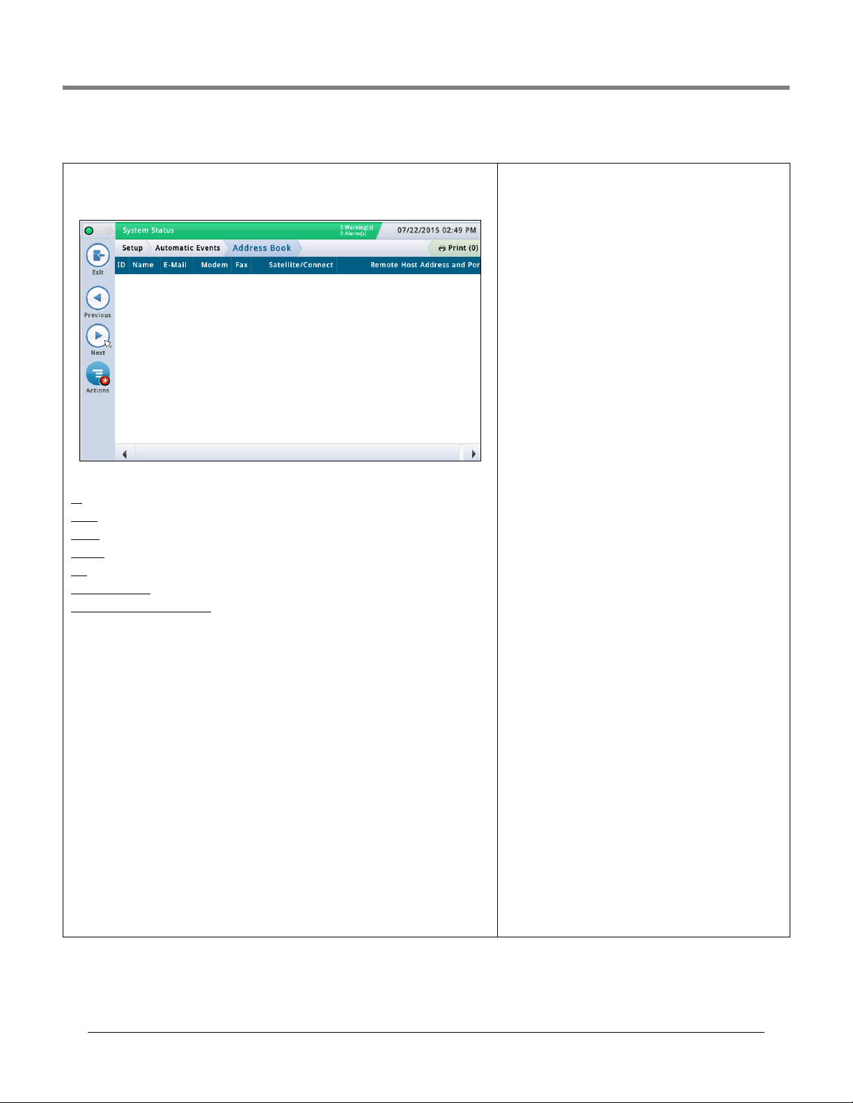
Initial Setup Of The Console Using Workflow Wizard Setup>Automatic Events>Address Book
Setup>Automatic Events>Address Book
This screen provides a list of your contact names and their outbound connectivity details. It
also lets you add or edit your contacts as necessary.
Screen Column Descriptions:
- An automatically assigned identifier number
ID
- Contact name
Name
E-Mail - Email address of the contact entry
- Computer modem phone number of the contact entry
Modem
- Fax modem phone number of the contact entry
Fax
Satellite/Connect - Satellite connection string and satellite COM port of contact entry
Remote Host Address and Port
- Remote host TCP/IP address and port of the contact entry
Adding/Editing a Contact
1. Do the following:
• If editing a contact, touch a record to modify (a checkmark appears next to the entry), then
touch Actions>Edit Contact.
• If adding a contact, touch Actions>Add Contact.
2. Enter or edit information in the appropriate fields below:
Name - Label for this contact.
Email - Email address of contact
Modem
Modem # (Computer) - Phone number of the modem
Modem COM Port - Comm Port of the modem installed on the console
Modem Dial-Out String - Add an alternate modem dial-out initialization string that
overrides the one stored in the Comm Device Setup screen. Leave this field blank to use
the modem dial-out initialization string stored on the Comm Device Setup screen.
NOTE: The Comm Device Setup screen must be changed on the console directly.
Modem Number of Retries - Number of times the console attempts to connect if
the last connection attempt fails.
Modem Retry Delay Time - Amount of time to wait between retry attempts.
FAX
FAX # (Computer) - Phone number of the Fax
machine.
FAX COM Port - Comm Port of the Fax modem
installed on the console.
FAX Dial-Out String - Add an alternate modem dial-
out initialization string that overrides the one stored in
the Comm Device Setup screen. Leave this field blank to
use the modem dial-out initialization string stored on the
Comm Device Setup screen.
NOTE: The Comm Device Setup screen must be changed
on the console directly.
FAX Number of Retries - Number of times the con-
sole attempts to connect if the last connection attempt
fails.
FAX Retry Delay Time - Amount of time to wait
between retry attempts.
TCP/IP
Remote TCP/IP Address - An IP address with the
format XXX.XXX.XXX.XXX; where XXX is from 0 to 255
(you can also specify a server address such as
myServer.bigg.com).
Remote TCP/IP Port - TCP/IP port of the remote
host.
Local TCP/IP COM Port - Local TCP/IP assignment.
TCP/IP Number of Retries - Number of times the
console attempts to connect if the last connection
attempt fails.
TCP/IP Retry Delay Time - Amount of time to wait
between retry attempts.
Satellite
Satellite Conn. String - Satellite connection string.
Satellite COM Port - Satellite assignment for the
current contact
Satellite Number of Retries - Number of times the
console attempts to connect if the last connection
attempt fails
Satellite Retry Delay Time - Amount of time to
wait between retry attempts.
48
Page 53
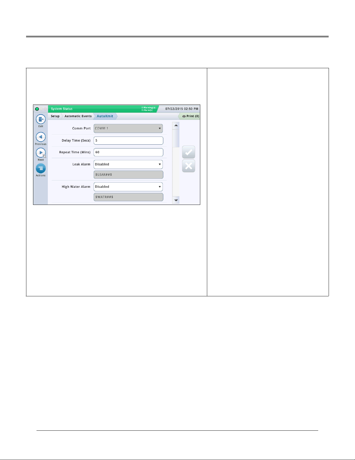
Initial Setup Of The Console Using Workflow Wizard Setup>Automatic Events>AutoXmit
Setup>Automatic Events>AutoXmit
This screen lets you set up messages that automatically transmit (AutoXmit) through an RS232 communication port when alarms are posted by the console.
NOTE: To use this feature, you need to have an RS-232 module installed on your console. The
Diagnostics>Module>Communication screen shows if this module is currently installed.
Comm Port
Touch to select a Comm port for serial communication (for example, "Comm.id1")
NOTE: Only Comm1 supports AutoXmit.
Delay Time (Secs)
Touch to enter an amount of time in seconds (up to 240) to wait after an alarm is posted by
the console before the message is sent.
Repeat Time (Mins)
[Field applies If you select "repeat" for any alarm message (see below)]
Touch to enter an amount of time (up to 240 minutes) to wait before the console retransmits
the message up until the alarm is cleared.
AutoXmit Alarm List
• Leak Alarm
• High Water Alarm
• Overfill Alarm
•Low Limit Alarm
• Theft Alarm
• Delivery Start Alarm
• Delivery Stop Alarm
• External Input On Alarm
• External Input Off Alarm
• Sensor Fuel Alarm
• Sensor Water Alarm
• Sensor Out Alarm
Selecting Alarms to Automatically transmit.
1. The default selection is Disable - Do not transmit a mes-
sage.
2. To transmit a message for an alarm, in the field next to
that alarm, touch the drop down arrow to select Transmit
or Repeat:
Tran sm it - Transmit one message when this alarm is
posted.
Repeat- Transmit a message continuously until the
alarm is cleared. Between transmissions wait for the
period of time specified in the Repeat Time (mins.)
field above.
3. The second field below each alarm shows the string format that controls how the message appears. Veeder-Root
recommends that you accept the default selection.
49
Page 54
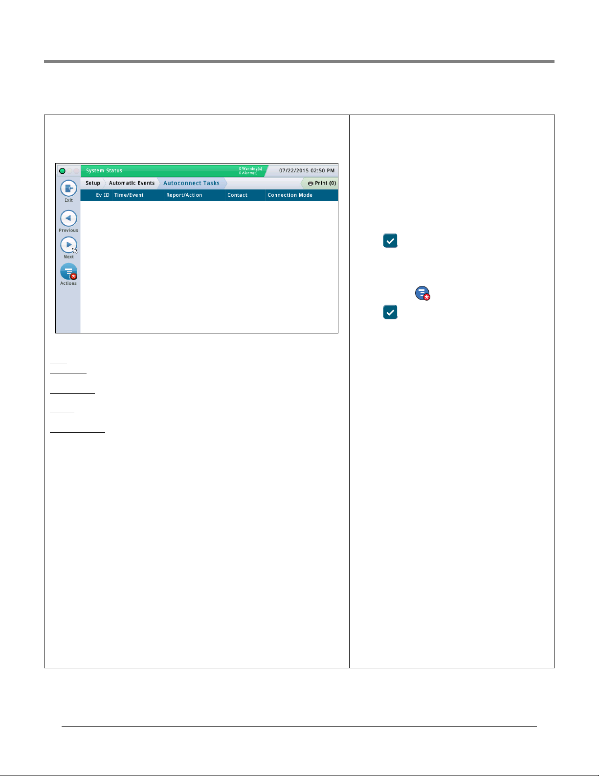
Initial Setup Of The Console Using Workflow Wizard Setup>Automatic Events>Autoconnect Tasks
Setup>Automatic Events>Autoconnect Tasks
This screen lets you view, add, edit, or delete tasks that automatically transmit information.
One task can involve many combinations of reports or actions, times, events, contacts, and
connection modes.
Screen Column Descriptions
Ev ID - Identifier automatically assigned to an event by the console.
Time/Event - Time or event that triggers the device-related task (e.g., daily at 3:00 PM). May
have more than one listed.
Report/Action
outbound connection).
Contact - Organization/person to be contacted (e.g., "ABC Mgmt.") as defined in Setup >
Automatic Events > Address Book.
Connection Mode - Device used (e.g., computer) and format of the data to be transmitted
(e.g., TCP/IP, Modem, FAX, Satellite, Email).
- Reports to be issued (e.g., inventory report), or the auto connect action (e.g.,
Adding or Editing A Task
1. Do the following:
• If editing a task, select a task entry to modify (a checkmark appears next to the entry),
then select Actions>Edit Task.
• If adding a task, select
2. Touch the fields below to enter the appropriate information:
Connection Mode
•Modem - To use, a USB modem must be installed to the console.
•Remote TCP/IP Address - To use, an Ethernet comm device must be installed in the console.
•Satellite - To use, a satellite comm device must be installed to the console.
•Email - To use, an e-mail feature must be installed on the console.
•Fax - To use, if a fax modem card must be installed in the console.
Reports
[only available if you select a connection mode of Email or Fax]
One (or more) reports that will be sent with the trigger.
Contact
Name of an address book contact (as defined in Setup>Automatic Events>Address
Book).
Actions>Add Task.
Trigger
Trigger for the automatic task:
On Time - Select the time and date for this autoconnect
task.
On Event - Select the event and/or alarm for this autocon-
nect task. Navigate to the proper sub-items in the list to
make your choice.
• Choices in capital letters (AUTO EVENT, CONTACT, COMM,
PRODUCT, TANK) are alarms
• Choices in upper and lower case (Delivery Start, Delivery
Complete, etc.) are events.
3. Touch to save your settings.
Deleting A Task
1. Select the task record entry that you want to delete (a
checkmark appears next to the entry).
2. Touch Actions then Remove Task.
3. Touch to save your settings.
50
Page 55
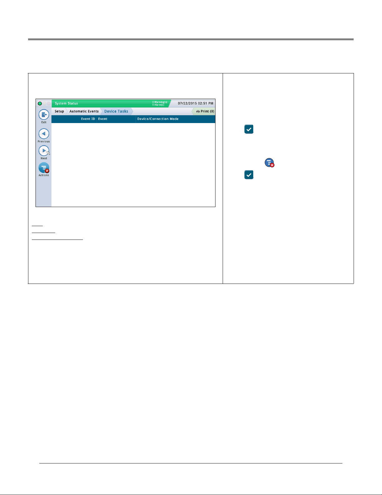
Initial Setup Of The Console Using Workflow Wizard Setup>Automatic Events>Device Tasks
Setup>Automatic Events>Device Tasks
This screen lists the device tasks currently configured for the console, and it also allows you
to add, edit, or delete these tasks.
Screen Column Descriptions
Ev ID - Identifier automatically assigned to an event by the console.
Time/Event - Event that triggers the task (for example, "Overfill Alarm").
Device/Connection Mode
(usually this is a relay, such as "Relay 1").
- Label of the device that is involved in performing the function
Adding or Editing A Task
1. Do the following:
• If editing a task, select a task record to modify (a checkmark appears next to the entry),
then select Actions>Edit Task.
• If adding a task, select
Actions>Add Task.
2. Touch the fields below to enter or edit the appropriate
information:
• Device - Select the relay from the list of available relays
on your console (you can also select other devices).
• Trig ge r - Select a trigger from the list of available triggers (Events). The triggers that you see depend on your
configuration. For example, a console alarm can be a trigger for a device task.
3. Touch to save your settings.
Deleting A Task
1. Select the task record entry that you want to delete (a
checkmark appears next to the entry).
2. Touch Actions then Delete Task.
3. Touch to save your settings.
51
Page 56
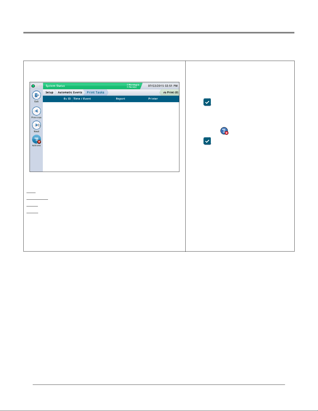
Initial Setup Of The Console Using Workflow Wizard Setup>Automatic Events>Print Tasks
Setup>Automatic Events>Print Tasks
This screen lists the printer-related automatic activities currently configured for the console,
and it also lets you add, edit, or delete these tasks.
Screen Column Descriptions
Ev ID - Console-automatically assigned identifier (1- 30) to an event
Time / Event
Report
Printer - Printer device label
- Time or event that triggers the task (e.g., Daily at 3:00 PM)
- Name of report to be printed
Adding or Editing A Task
1. Do the following:
• If editing a task, select a task record to modify (a checkmark appears next to the entry),
then select Actions>Edit Task.
• If adding a task, select Actions>Add Task.
2. Touch the fields below to enter or edit the appropriate
information:
• Event - Select the Event that will trigger the task
(depends on your configuration).
• Printer - Select the printer printing this task.
• Report - Select the report (or reports) to print.
3. Touch to save your settings.
Deleting A Task
1. Select the task record entry that you want to delete (a
checkmark appears next to the entry).
Actions then Delete Task.
2. Touch
3. Touch to save your settings.
52
Page 57

Initial Setup Of The Console Using Workflow Wizard Setup>Automatic Events>All Tasks
Setup>Automatic Events>All Tasks
This screen lists tasks that automatically transmit information. One task can involve many
combinations of reports or actions, times, events, contacts, and connection modes. You can
store up to 30 auto connect tasks.
Screen Column Descriptions
Ev Id - Identifier automatically assigned to an event by the
console.
Time / Event
task (e.g., "Leak Alarm: Disabled"); may have more than one
listed.
Report / Action
Report"), or the auto connect action (e.g., "AutoXmit").
Contact - Organization/person to be contacted (e.g., ABC
Mgmt.) as defined in Setup > Automatic Events > Address
Book.
Device / Connection Mode
format of the data to be transmitted (e.g., "EMAIL", etc.).
- Time or event that triggers the device-related
- Reports to be issued (e.g., "Inventory
- Device used (e.g., "Co 1") and
53
Page 58

Initial Setup Of The Console Using Workflow Wizard System Administration>Roles Admin
Is Regulator Lets you choose whether this role is
regulator role or not (the regulator role
can review the console reports)
Screen Lets you view permissions by program
section. Click on the down arrow by
the section to view the permissions of
individual programs within that
section.
Not Granted Designates that permissions to
view or edit/perform have not been
granted to this program or program
section
View
Designates that this program or
program section can be viewed by this
role
Edit/Perform
Designates that this program or
program section can be
edited/performed by this role
Is Regulator
Lets you choose whether this role is
regulator role or not (the regulator role can
review the console reports)
Screen
Lets you view permissions by program
section. Click on the down arrow by the
section to set the permissions of individual
programs within that section.
Not Granted
Designates that permissions to view or
edit/perform have not been granted to this
program or program section
View
Designates that this program or program
section can be viewed by this role
Edit/Perform
Designates that this program or program
section can be edited/performed by this role
System Administration>Roles Admin
This screen lets you set up roles (levels of security) and customize how each role should
behave for a user who is assigned to that role.
Setting up a role involves specifying the screens that a user can view and/or edit/perform.
• The first user created must have the admin role.
• Only users with an Administrator role can add, edit, or delete roles.
• You cannot edit or delete the Predefined Roles of Administrator or Operator.
• For the user login feature to be activated, you need to
rity
field in “Setup>System>Security” screen.
Enable the Front Panel Secu-
Predefined Roles Description
Administrator - Able to edit console configuration, perform software upgrades, generate
reports, and start various diagnostic tests. Also able to create new roles and users.
Operator - Able to view and generate reports and perform certain manual functions, like a
manual delivery.
Custom Roles Description
• Regulator - Can print and review the console reports.
•Any custom roles you have created - User- defined.
Viewing Role Permissions (available to an Administrator user only)
1. Touch Actions>View Permissions:
2. View the permissions by program section or by individual
program as describe below:
Field Description
3. Touch the X in the upper right corner of the screen to exit
the screen.
Adding a Role (available to an Administrator user only)
1. Touch Actions>Add Role:
2. Enter information in the Add New Role fields as described
below:
Field Description
Role Name of Role
3. Touch to save your entry. Touch and touch the
X in the upper right corner to exit without saving changes.
Continued on next page
54
Page 59
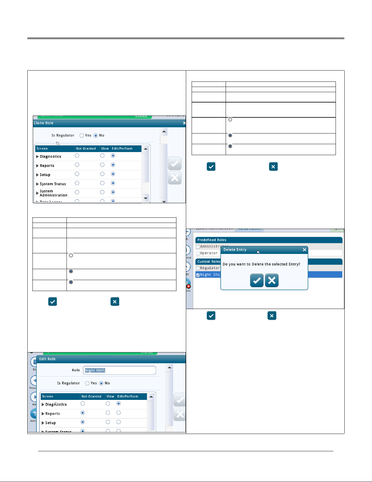
Initial Setup Of The Console Using Workflow Wizard System Administration>Roles Admin
Is Regulator
Lets you choose whether this role is regulator role or
Screen
Lets you set permissions by program section. Click on
the down arrow by the section to set the permissions
of individual programs within that section.
Not Granted
Designates that permissions to view or edit/perform
have not been granted to this program or program
View
Designates that this program or program section can
Edit/Perform
Designates that this program or program section can
System Administration>Roles Admin - Concluded
Cloning A Role (available to an Administrator user only)
Cloning a role lets you copy a role (and all of its permissions) to use as a
starting point when creating a new role. This lets you save setup time when
the new role is similar in nature to an existing role.
1. Select a role to clone (a checkmark appears next to the entry), then select
Actions>Clone Role:
2. Enter information in the Clone Role fields as described below::
Field Description
Role Name of Role
not (the regulator role can review the console reports).
2. Enter information in the Edit Role fields as described below:
Field Description
Role Name of Role
not.
section.
be viewed by this role.
be edited/performed by this role.
3. Touch to save your entry. Touch and touch the X in the upper
right corner to exit without saving changes.
Deleting A Role (available to an Administrator user only)
NOTE: You can not delete the Operator or Administrator roles. Also, no user
can be assigned to a role that you want to delete (the Delete option will be
unavailable). In that situation, reassign users to another role, or delete
users assigned to that role, before deleting that role.
1. Select a role to delete (a checkmark appears next to the entry), then select
Actions>Delete Role:
section.
be viewed by this role.
be edited/performed by this role.
3. Touch to save your entry. Touch and touch the X in the upper
right corner to exit without saving changes.
Editing A Role (available to an Administrator user only)
NOTE: You cannot edit the Operator or Administrator roles.
1. Select a role to modify (a checkmark appears next to the entry), then
select Actions>Edit Role:
.
2. Touch to delete selected role or to cancel deletion.
55
Page 60

Initial Setup Of The Console Using Workflow Wizard System Administration>Users Admin
User Login name of user (cannot have
spaces).
Role Level of security for that user -
choices are:
• Administrator
• Operator
• Regulator
• Any custom roles that you have
setup for (example, "Manager").
See Action>Help>System
Administration> Roles Admin
Password Password for user (minimum of 3;
maximum of 123 alpha-numeric
Repeat Password Repeat entry of password to
Force Change Password
[checkbox]
When checked, forces the user to
enter a new password then next
time the user logs on to the
console.
Email Email address of user
Role
[field accessible by an
Administrator user only]
Level of security for that user -
choices are:
• Administrator
• Operator
• Regulator
• Any custom roles that you have
setup for (example, "Manager").
See Action>Help>System
Administration> Roles Admin
Change Password
[checkbox]
When checked, let's a user
change his/her password while in
Password Password for user (minimum of 3
Repeat Password Repeat entry of password to
Force Change Password
[checkbox]
[field accessible by an
When checked, forces the user to
enter a new password then next
time the user logs on to the
System Administration>Users Admin
This screen lets you set up users with different roles (levels of security) so you can control a
user's access to specific screens on the console. This is necessary when you want to ensure
untrained personal are not changing the programming and possibly disabling different
aspects of your compliance reporting. NOTE: the first user created must have the admin role.
IMPORTANT
• If this is the first time you are entering users on the console, you have full access to add,
modify, or delete users at any role (level). Once you setup users, however, only users with
an Administrator role have the ability to add or delete users.
• After you add a user, make sure you enable the Front Panel Security field in “Setup>System>Security” screen for the user login feature to be activated.
The data in this columns of this screen will differ for Users and Administrators as follows:
Logged in User
User - Login name of the person who is currently logged in.
Full Name - Full name of the logged in user.
Role - Role (level of security) assigned to the logged in user.
Email - Email address of logged in user.
Logged In Administrator User
User - Login name of the Admin user.
Full Name - Full name of the Admin user.
Role - Role (level of security) assigned to that Admin user.
Email - Email address of that Admin user.
2. Enter information in the Add User fields as described
below:
Field Description
Full Name Full name of user.
Email Email address of user.
topic for more information.
characters).
confirm.
3. Touch to save your entry. Touch and touch the
X in the upper right corner to exit without saving changes.
Editing a User (available to that user and/or an Adminis-
trator user) - NOTE: there has to be at least one user with an
Admin role.
You may need to edit a user if a person’s responsibility has
changed and you need to reassign their role.
1. Select a user to modify (a checkmark appears next to the
entry), then select
Actions>Edit User.
2. Change information in the following fields. NOTE: You cannot change the login name of a user. If you need to change
the login name, delete the user, and then re-enter a new
user with a login name you desire.
Full Name Full name of user
Field
Description
Adding a User (available to an Administrator user only)
Actions>Add User:
1. Select
56
Administrator user only]
Continued on next page
topic for more information.
this screen
alpha-numeric characters)
confirm
console
Page 61

Initial Setup Of The Console Using Workflow Wizard Setup>System>Security
System Administration>Users Admin - Concluded
3. Touch to save your entry. Touch and touch the X in the upper
right corner to exit without saving changes.
Deleting a User (available to an Administrator user only)
NOTE: You can not delete or reassign the role of the last Admin user - there
has to be at least one user with an Admin role.
1. Select a user to delete (a checkmark appears next to the entry, and then
select Actions>Delete User.
2. Touch to delete selected role or to cancel deletion. .
Setup>System>Security
This screen lets you enable the front panel security feature which requires a password for a
user to login to the console. With this feature disabled (i.e., no password required), all users
can access all screens. When enabled, users must login with the appropriate password to
gain access to the programs they are allowed to view (as set up in the“System Administra-
tion>Users Admin” screen). This is helpful when you want to limit access to sensitive areas
of the system, such as the setup and diagnostic screens.
NOTES:
• This feature cannot be enabled until an Administrator account has been created (done in
the System Administration>Users Admin screen).
• Once the Front Panel Security field is enabled, you must enter the correct password or you
will remain in the logged-out mode. In the logged-out mode, you can only view a very lim-
ited number of screens (such as system status).
Front Panel Security
Touch to enable or disable the Front Panel Security feature.
Serial Command Port (TCP/IP Interface)
Default is enabled.
This will completely disable access to the serial command
port via Ethernet. The port is defined under Setup > Com-
munication > Ethernet Port Serial Command Port (default is
10001).
Serial commands should still continue to function via the
physical RS232 interface (Serial COM Port 1 & 2).
•Serial Command Port: This is the port many companies use
for entering RS232/Serial commands via TCP/IP port 10001.
Disabling this will prevent remote systems from changing
parameters on the gauge.
User Admin via Web
Default is enabled
The “User Admin via Web” setting will allow an Administra-
tor to provide user administration via the web.
Today, it is possible to configure user’s via web. The “user
Management via Web” control will allow the system administrator to enable / disable the “Users Admin” link on the
screen System Administration > Users Admin. Note: this
only enables / disables access to System Administration >
Users Admin.
The users will still be able to login to the Web, if they have
Web access rights.
57
Page 62

Software Maintenance
System Status
07/20/2015 09:10 AM
0 Warning(s)
0 Alarms(s)
Print (0)
Home
Favorites
Menu
Actions
Software Maintance
Current Version
Available Version
Current Operations
6.F.230.72
6.E.230.70
Click to acknowledge the system will be
stopped.
IDLE
Activate/Revert
This section contains information on TLS-450PLUS and TLS4 software maintenance screens. Veeder-Root recommends
frequent database backups to ensure setup and report data archives are up to date.
Touch the Menu>Software Maintenance icons to view a list of the available Software Maintenance screens:
Figure 5. Software Maintenance Screen
Activate/Revert Screen (Menu>Software Maintenance>Activate/Revert)
This screen lets you activate newly installed software or revert to a previously stored version of software. During the
activation process, several dialog boxes will be displayed to inform you of key events.
NOTE: Activation will reboot the console and could interrupt dispensing.
58
Page 63

Software Maintenance Notes on Reverting to a Previous Software Version
Notes on Reverting to a Previous Software Version
A copy of the previous (older) system software and databases is stored on the console SD card. If the current (newer)
version of system software/features does not perform properly, the Revert operation gives you the ability to revert to the
previous software version stored in the SD card. No USB devices are required for the revert operation.
During feature activation, which only takes a few minutes, there must be no dispensing.
Table 1. Activate/Revert Screen Field Descriptions
Field Description
Current Version Current version of software (x.xx xxx.x) installed in the console
Available Version Version of software that can be accessed by the console (Not Available will display if a version of soft-
Current Operation Status of the console:
Connection Message Not applicable to a revert or upgrade process.
Disclaimer Lists any messages for the newly activated software.
Click to acknowledge the system will be stopped [check
box]
Revert Starts the actual Revert process.
Activate Starts the actual Activate process.
ware has not been stored).
Idle (no software is being installed or reverted), or
Activating (a software install is in progress)
Select this check box to agree to start a software install/reversion procedure.
Note: When you click Revert, a confirmation prompt displays, letting you know that the system will restart
(reboot) to do the revert. If the system is not in use, Touch the button to continue. The system
reboots and the system is reverted.
Note: When you click Activate, a confirmation prompt displays, letting you know that the system will
restart (reboot) to do the revert. If the system is not in use, Touch the button to continue. The system reboots and the new system software is activated.
59
Page 64
Software Maintenance Example Database Backup Procedure
System Status
07/20/2013 09:10 AM
0 Warning(s)
0 Alarms(s)
Print (0)
Home
Favorites
Menu
Actions
Software Maintenance
Current Version
Available Version
Current Operations
Backup Destination
Version
1.gB 230.4
Not available
Select a source to retrieve versions available
IDLE
DB Backup
Select destination device
DB Backup (Menu>Software Maintenance>DB Backup)
This screen lets you backup the data file of the console. A FAT32 formatted USB thumb drive is required.
Note: a thumb drive will only store 5 backups. On the 6th backup, the oldest backup record is deleted from the thumb
drive.
K
eep the V-R Code/Feature and Recovery USB thumb drives in a secure location.
Table 2. DB Backup Screen Field Descriptions
Field Description
Current Version Current version of software (x.xx xxx.x) installed in the console
Available Version Not applicable to a backup.
Current Operation Status of the console:
Idle (no backup procedure is executing), or
Discovering Backup Device (system is validating installed thumb drive)
Backup Operation has started (backup is in progress)
Connection Message Lists any messages that may occur between the device and the console.
Backup destination Backup destination (device) for your data files (the normal choice is “Thumb drive”)
Version USB drive name.
Backup Starts the actual backup.
Backup Progress Completion percentage of backup process.
Example Database Backup Procedure
NOTE: A valid backup thumb drive must be Windows FAT32 formatted and must have at least 4 GB of available memory.
1. Insert the backup thumb drive into one of the console’s USB ports.
2. Navigate to the Menu>Software Maintenance>DB Backup screen.
3. Select thumb-drive as the backup destination. Notice the Version field displays thumb drive information.
4. Touch Backup button to begin the backup.
5. After completing the backup, the ‘Backup Completed Successfully!’ message appears.
60
Page 65
Software Maintenance Example Database Backup Procedure
6. Remove the thumb drive and put it in a secure location.
NOTE: For ultimate protection against possible loss of data and to protect against system crashes, run the DB Backup
operation weekly.
DB Restore (Menu>Software Maintenance>DB Restore)
System Status
Software Maintenance
Home
Favorites
Menu
Actions
Current Version
Available Version
Current Operations
Backup Destination
Version
0 Warning(s)
0 Alarms(s)
DB Restore
1.gB 230.4
Not available
IDLE
Select destination device
Select a source to retrieve versions available
07/20/2013 09:10 AM
Print (0)
This screen lets you restore the data files of the console. A valid USB recovery thumb drive (with previously backed up data
from this console) is required.
eep the V-R Code/Feature and Recovery USB thumb drives in a secure location.
K
Table 3. DB Restore Screen Field Descriptions
Field Description
Current Version Current version of software (x.xx xxx.x) installed in the console
Available Version Version of software that can be accessed by the console (Not applicable to a backup).
Current Operation Status of the console:
Idle (no restore procedure is executing), or
Discovering Restore Device (system is validating installed thumb drive)
Restore Operation in Progress (restore is in progress)
Connection Message Lists any messages that may occur between the device and the console.
Restore destination Select the device containing the data files for the restore (the normal choice is "Thumbdrive").
Version Date and software version of when the data archive was created.
Restore Starts the actual restore.
Note: When you click Restore, a confirmation prompt displays, letting you know that the system will
restart (reboot) to do the restore. If the system is not in use, touch the button to continue. The system reboots and the database is restored.
Restore Progress Completion percentage of restore process.
61
Page 66

Software Maintenance Example Software Download Procedure
System Status
07/20/2013 09:10 AM
0 Warning(s)
0 Alarms(s)
Print (0)
Home
Favorites
Menu
Actions
Software Maintenance
Current Version
Available Version
Current Operations
Backup Destination
Version
1.gB 230.4
Not available
Select a source to retrieve versions available
IDLE
Download
Select Source
Download (Menu>Software Maintenance>Download)
This screen lets you do USB downloads from either a valid V-R Code/Features USB thumb drive or a V-R Recovery USB
thumb drive that is plugged into a USB port in the console.
K
eep the V-R Code/Feature and Recovery USB thumb drives in a secure location.
Table 4. Download Screen Field Descriptions
Field Description
Current Version Current version of software (x.xx xxx.x) installed in the console
Available Version Version of software that can be accessed on the USB drive.
Current Operation Status of the console:
Idle (no backup procedure is executing),
Scanning Devices (system is validating installed thumb drive),
Reading Update List
Downloading
Connection Message Lists any messages that may occur between the device and the console.
Download Source Device where the files are coming from.
Version Date and software version of when the data archive was created.
Download Starts the actual download.
NOTE: When you click Download, a confirmation prompt displays, letting you know that the system will
restart (reboot) to do the download. If the system is not in use, touch the button to continue. The
system reboots and the database is restored.
Download Progress Completion percentage of download process.
Example Software Download Procedure
1. Insert the Software Maintenance thumb drive into one of the USB ports.
2. Navigate to the Menu>Software Maintenance>Download screen.
62
Page 67
Software Maintenance Example Software Download Procedure
System Status
07/20/2013 09:10 AM
0 Warning(s)
0 Alarms(s)
Print (0)
Home
Favorites
Menu
Actions
Software Maintenance
Current Version
Available Version
Current Operations
Snapshot Destination
Version
1.gB 230.4
Not available
Select a source to retrieve versions available
IDLE
System Snapshot
Select destination device
3. Touch the Download Source down arrow and select the thumb drive. Notice the Version field displays contained
software version.
4. Touch the Download button to begin the software download.
5. After successful completion of the download (approximately 30 minutes), the ‘Download Completed’ message
appears.
6. Navigate to the Menu>Software Maintenance>Activate/Revert screen. Notice the Current version and Available
(downloaded) version are displayed.
7. Touch the box beside the message ‘Click to acknowledge the system will be stopped.’
8. Touch the Activate button to overwrite the Current of software with the Available (just downloaded) version of software.
9. The Confirmation Needed dialog box displays. Touch the
button to confirm and activate the new software, or touch
the X button to cancel the activation.
System Snapshot (Menu>Software Maintenance>System Snapshot)
If a problem cannot be diagnosed over the phone with technical support, Tech Support may request a System Snapshot be
taken and returned V-R. The System Snapshot captures comprehensive system data to facilitate a thorough problem
analysis. This screen lets you copy a System Snapshot to a USB thumb drive that is plugged into a USB port in the
console.
Table 5. System Snapshot Screen Field Descriptions
Field Description
Current Version Current version of software (x.xx xxx.x) installed in the console
Available Version Previous version of software or Not Available message.
Current Operation Status of the console:
Idle
Activate Snapshot
Snapshot Destination Select destination device
Version Describes the destination device.
63
Page 68
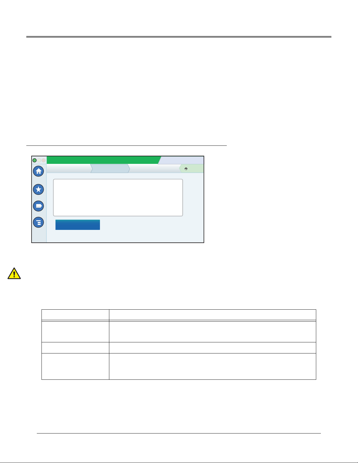
Software Maintenance Example System Snapshot Procedure
Example System Snapshot Procedure
1. Insert a USB thumb drive with at least 10 Mb of free space into one of the USB ports.
2. Navigate to the Menu>Software Maintenance>System Snapshot screen.
3. Touch the Snapshot Destination field down arrow and select the thumb drive. Notice the Version field displays
information about the thumb drive.
4. Touch the Take Snapshot button to begin the procedure.
5. After successful completion of the snapshot (approximately 3 minutes), the ‘Snapshot Completed’ message appears
and you can remove the thumb drive.
Upgrade Features (Menu>Software Maintenance>Upgrade Features)
System Status
Software Maintenance Upgrade Features
Home
Expansion box
SLD
Favorites
Menu
Actions
3.0 GPH PLLD
ATG Functionality
Datalogger Functionality
Install features
0 Warning(s)
0 Alarms(s)
07/20/2013 09:10 AM
Print (0)
This screen lets you activate features to be installed on your console. During the activation process, several dialog boxes
will be displayed to inform you of key events.
During feature activation, which only takes a few minutes, there must be no dispensing!
Following activation, the console converts the setup databases. Once new features are installed, setup(s) relevant to the
new feature(s) will be required.
Table 6. Upgrade Features Screen Field Descriptions
Field Description
Feature (box) List features which are available to be activated. Multiple features may be activated concurrently. Select
the boxes beside each of the desired items in this column. If you change your mind about a selection,
select the box again to remove the check.
Install features button Touch to start the installation process.
Status [during installation] Current status of each feature with one of the following messages:
Ready to Activate
Activation in Progress
64
Page 69

For technical support, sales or
other assistance, please visit:
www.veeder.com
 Loading...