

Page 1

Installation Manual
MAG-XL Flex Probe
Manual No: 577013-972 ● Revision: E
Page 2

Notice
Veeder-Root makes no warranty of any kind with regard to this publication, including, but not limited to, the implied warranties of
merchantability and fitness for a particular purpose.
Veeder-Root shall not be liable for errors contained herein or for incidental or consequential damages in connection with the
furnishing, performance, or use of this publication.
Veeder-Root reserves the right to change system options or features, or the information contained in this publication.
This publication contains proprietary information which is protected by copyright. All rights reserved. No part of this publication
may be photocopied, reproduced, or translated to another language without the prior written consent of Veeder-Root.
Contact TLS Systems Technical Support for additional troubleshooting information at 800-323-1799.
DAMAGE CLAIMS / LOST EQUIPMENT
Thoroughly examine all components and units as soon as they are received. If any cartons are damaged or missing, write a
complete and detailed description of the damage or shortage on the face of the freight bill. The carrier's agent must verify the
inspection and sign the description. Refuse only the damaged product, not the entire shipment.
Veeder-Root must be notified of any damages and/or shortages within 30 days of receipt of the shipment, as stated in our Terms
and Conditions.
VEEDER-ROOT’S PREFERRED CARRIER
1. Contact Veeder-Root Customer Service at 800-873-3313 with the specific part numbers and quantities that were missing
or received damaged.
2. Fax signed Bill of Lading (BOL) to Veeder-Root Customer Service at 800-234-5350.
3. Veeder-Root will file the claim with the carrier and replace the damaged/missing product at no charge to the customer.
Customer Service will work with production facility to have the replacement product shipped as soon as possible.
CUSTOMER’S PREFERRED CARRIER
1. It is the customer’s responsibility to file a claim with their carrier.
2. Customer may submit a replacement purchase order. Customer is responsible for all charges and freight associated with
replacement order. Customer Service will work with production facility to have the replacement product shipped as soon as
possible.
3. If “lost” equipment is delivered at a later date and is not needed, Veeder-Root will allow a Return to Stock without a restocking
fee.
4. Veeder-Root will NOT be responsible for any compensation when a customer chooses their own carrier.
RETURN SHIPPING
For the parts return procedure, please follow the appropriate instructions in the "General Returned Goods Policy” pages in the
"Policies and Literature" section of the Veeder-Root North American Environmental Products price list. Veeder-Root will not
accept any return product without a Return Goods Authorization (RGA) number clearly printed on the outside of the package.
FCC INFORMATION
This equipment complies with the requirements in Part 15 of the FCC rules for a Class A computing device. Operation of this
equipment in a residential area may cause unacceptable interference to radio and TV reception requiring the operator to take
whatever steps are necessary to correct the interference.
©Veeder-Root 2012. All rights reserved
.
Page 3

Warranty
TLS-350R, TLS-350 PLUS, TLS-350J AND TLS-300I/C MONITORING SYSTEMS
We warrant that this product shall be free from defects in material and workmanship for a period of one (1) year from the date of
installation or twenty-four (24 months) from the date of invoice, whichever occurs first. During the warranty period, we or our
representative will repair or replace the product, if determined by us to be defective, at the location where the product is in use
and at no charge to the purchaser. LAMPS, FUSES, AND LITHIUM BATTERIES ARE NOT COVERED UNDER THIS
WARRANTY.
We shall not be responsible for any expenses incurred by the user.
This warranty applies only when the product is installed in accordance with Veeder-Root’s specifications, and a Warranty
Registration and Checkout Form has been filed with Veeder-Root by an authorized Veeder-Root Distributor. This warranty will not
apply to any product which has been subjected to misuse, negligence, accidents, systems that are misapplied or are not installed
per Veeder-Root specifications, modified or repaired by unauthorized persons, or damage related to acts of God.
If “Warranty” is purchased as part of the Fuel Management Service, Veeder-Root will maintain the equipment for the life of the
contract in accordance with the written warranty provided with the equipment. A Veeder-Root Fuel Management Services
Contractor shall have free site access during Customer’s regular working hours to work on the equipment. Veeder-Root has no
obligation to monitor federal, state or local laws, or modify the equipment based on developments or changes in such laws.
MODULES, KITS, OTHER COMPONENTS (PARTS PURCHASED SEPARATE OF A COMPLETE CONSOLE)
We warrant that this product, exclusive of lithium batteries, shall be free from defects in material and workmanship for
a period of fifteen (15) months from date of invoice. We warrant that the lithium batteries shall be free from defects
in material and workmanship for a period of 90 days from date of invoice. We will repair or replace the product if the
product is returned to us; transportation prepaid, within the warranty period, and is determined by us to be defective.
This warranty will not apply to any product which has been subjected to misuse, negligence, accidents, systems that
are misapplied or are not installed per Veeder-Root specifications, modified or repaired by unauthorized persons, or
damage related to acts of God.
We shall not be responsible for any expenses incurred by the user.
MAG-XL FLEX PROBE
The same warranty policies for the MAG Plus Rigid Probe apply to MAG-XL Flex Probe. When the Probe is
purchased with a monitoring system (console), the warranty period is one (1) year from the date of installation or
twenty-four (24) months from the invoice date, whichever occurs first. Parts and labor are covered in this warranty.
When the Probe is purchased individually, it has a 15-month parts only warranty from the invoice date. Please refer
to the Policies and Literature section in the Price Book.
Veeder-Root will not warranty the probe if its damage is caused by failing to follow the Veeder-Root MAG-XL
Installation & Setup Manual (577013-972). Each MAG-XL Flex Probe is made to order, and therefore cannot be
returned for credit.
Page 4

Introduction
System Requirements ......................................................................................................1
Contractor Certification Requirements ..............................................................................1
Related Documents ..........................................................................................................2
Product Marking Information .............................................................................................2
Related Documents ..................................................................................................2
Safety Warnings ...............................................................................................................4
Safety Symbols .................................................................................................................4
GENERAL PRECAUTIONS ..............................................................................................5
SPECIAL TOOLS REQUIRED .................................................................................5
General AST Guidelines ...................................................................................................5
AST Construction Safe Work Practices ............................................................................6
Personal Protective Equipment ........................................................................................6
Before you Begin ..............................................................................................................6
MAG-XL Flex Probe Operating Parameters .....................................................................7
National Electrical Code Compliance ................................................................................8
MAG-XL Flex Probe Wire Length .............................................................................8
Veeder-Root Parts ............................................................................................................8
Customer Supplied Parts ..................................................................................................8
Example Drawings
Example MAG-XL Flex Probe Site Layout Drawing ..........................................................9
MAG-XL Flex Probe Dimensions ....................................................................................10
Example MAG-XL Flex Probe Installation in Tank Manway ...........................................12
Example MAG-XL Flex Probe Installation in Existing Tank Opening ..............................13
Component Dimensions .................................................................................................14
Table of Contents
MAG-XL Flex Probe Installation
Pre-Installation Component Setup and Functional Check ..............................................15
Assemble the Battery Pack Mounting Bracket ................................................................15
Probe Installation - Manway 4-Inch Riser Pipe.......................................................15
Probe Installation - Top of Tank 2-Inch Pipe Opening............................................15
Unpack the MAG-XL Flex Probe ....................................................................................16
Assemble the MAG-XL Flex Probe Components ............................................................17
Probe Installation - Manway 4-Inch Riser Pipe.......................................................17
Probe Installation - Top of Tank 2-Inch Pipe Fitting ...............................................18
Install the MAG-XL Flex Probe Assembly .......................................................................19
Probe Installation - Manway 4-Inch Riser Pipe.......................................................19
Probe Installation - Top of Tank 2-Inch Pipe Fitting ...............................................20
Installing the TLS XL-Transmitter ...................................................................................20
TLS XL-Transmitter Installation - Manway 4-Inch Riser Pipe (ref. Figure 13) ........20
TLS XL-Transmitter Installation - Top of Tank 2-Inch Pipe fitting (ref. Figure 14) ..21
Connecting MAG-XL Flex Probe Wiring .........................................................................23
TLS Console Setup for MAG-XL Flex Probe
Height Reading Adjustment ............................................................................................26
TLS Limit Calculations ....................................................................................................28
Limit Calculation Example ......................................................................................28
Vertical Tank Volume Calibration ....................................................................................30
iviv
Page 5

Figures
Table of Contents
MAG-XL Flex Probe Troubleshooting
Troubleshooting ..............................................................................................................31
Probe Out or No Probe Detected ...........................................................................31
Incorrect Product Height Reading ..........................................................................31
Figure 1. Site drawing - example TLS RF wireless 2 system site layout –
two Mag-XL Probes ................................................................................9
Figure 2. MAG-XL Flex Probe parameters ..........................................................10
Figure 3. MAG-XL Flex Probe installation with riser pipe, top mounted
in tank man way ....................................................................................12
Figure 4. MAG-XL Flex Probe installation without riser pipe, top mounted
in existing tank opening ........................................................................13
Figure 5. Wireless component dimensions ..........................................................14
Figure 6. Attaching conduit hangers to battery mounting bracket ........................16
Figure 7. Do not bend top 2 feet of probe ............................................................17
Figure 8. Do not twist one coil 90° from the others ..............................................17
Figure 9. MAG-XL Flex Probe components - man way install .............................18
Figure 10. MAG-XL Flex Probe components - pipe fitting install ...........................18
Figure 11. Correctly lowering probe into tank ........................................................19
Figure 12. Incorrectly lowering probe into tank ......................................................19
Figure 13. Installing TLS XL-Transmitter - man way riser pipe .............................22
Figure 14. Installing TLS XL-Transmitter - tank 2-inch pipe fitting .........................23
Figure 15. Connecting input wiring to transmitter terminal blocks .........................24
Figure 16. Connecting probe and battery pack cables to the
TLS XL-Transmitter ..............................................................................24
Figure 17. In-tank setup for TLS Consoles used with MAG-XL Flex Probes .........27
Figure 18. Alarm Limit Settings ..............................................................................29
Figure 19. Volume calibration examples ................................................................30
Tables
Table 1. MAG-XL Flex Probe Specifications .........................................................11
v
Page 6

Introduction
The MAG-XL RF wireless probe is designed for inventory-only monitoring of extra large in-ground and aboveground tanks in applications where in-ground probe wiring is either impractical or non-existent. Procedures
contained within this manual include:
• Installing the MAG-XL Flex Probe in the top of the tank.
• Mounting the TLS XL-Transmitter and battery pack to the tank riser
• Connecting the MAG-XL Flex Probe cable and battery pack cable to the transmitter.
Other required devices, such as the TLS RF Wireless 2 (W2) System and the TLS console are to be installed
following instructions shipped with those devices.
IMPORTANT!
It is imperative that you read and follow the handling warnings and installation instructions discussed
in this manual to avoid damaging the MAG-XL Flex Probe and voiding the warranty.
System Requirements
The Veeder-Root Wireless 2 (W2) System replacement/spare parts are listed below:
• 330020-668 TLS RF Console for Wireless 2 & MAG-XL Flex Probes
• 330020-673 MAG-XL Transmitter for MAG-XL Flex Probes
• 330020-674 Transmitter for Wireless 2 devices
• 330020-669 Receiver for Wireless 2 & MAG-XL Flex Probes
• 330020-670 Repeater for Wireless 2 & MAG-XL Flex Probes
Contractor Certification Requirements
Veeder-Root requires the following minimum training certifications for contractors who will install and setup the
equipment discussed in this manual:
Installer (Level 1) Certification: Contractors holding valid Installer Certification are approved to perform wiring
and conduit routing; equipment mounting; probe, sensor and carbon canister vapor polisher installation; wireless
equipment installation; tank and line preparation; and line leak detector installation.
ATG Technician (Level 2/3 or 4) Certification: Contractors holding valid ATG Technician Certifications are
approved to perform installation checkout, startup, programming and operations training, system tests,
troubleshooting and servicing for all Veeder-Root Series Tank Monitoring Systems, including Line Leak Detection.
In addition, Contractors with the following sub-certification designations are approved to perform installation
checkout, startup, programming, system tests, troubleshooting, service techniques and operations training on the
designated system.
• Wireless 2
• Tall Tank
Warranty Registrations may only be submitted by selected Distributors.
1
Page 7

Introduction Related Documents
Related Documents
577013-964 TLS RF Wireless 2 System (W2) Installation and Maintenance Guide
Product Marking Information
RELATED DOCUMENTS
Documents Required to Install Equipment
This intrinsically safe apparatus is only for use as part of a Veeder-Root Automatic Tank Gauging System (ATG
Console with probes and sensors). To install intrinsically safe apparatus, use the specific control drawing that
appears on the nameplate of the applicable associated apparatus (ATG Console):
Equipment
Associated Apparatus
TLS-450/8600 331940-008
TLS-350, TLS-350R 331940-011
TLS-300 331940-013
TLS-50 or TLS2 or TLS-IB 331940-014
TLS4/8601 331940-018
TLS-XB/8603 331940-019
Intrinsically Safe Apparatus for Wireless Applications
Tank Gauge Accessories 331940-012
UL/cUL Control Drawing
Document No.
The control drawings contain information related to the correct installation of the overall intrinsically Safe System.
This includes information such as maximum number of apparatus, specific apparatus allowed in the system,
maximum cable lengths, references to codes, proper grounding and so on. Control drawings can be found on the
accompanying Compact Disk (TECH DOCS CD) or on the internet at veeder.com under SUPPORT; VR
TECHNICAL DOCUMENTS; DRAWINGS.
2
Page 8

Introduction Product Marking Information
CLASS I, Division 1, Group D
CLASS 1, Zone 0, Group IIA
Hazardous Location
Intrinsically Safe (I.S.) Apparatus
XL TRANSMITTER
VT : 6.1 V
I
T
: 208 mA
P
o
: 0.32 W
C
o
: 500 µF
L
o
: 3.0 mH
COMMON (-)
GENERAL PRODUCT WIRING DIAGRAM
POWER (+)
INPUT
POWER
DATA
+
Probe Output Ratings
INTRINSICALLY SAFE APPARATUS INTRINSICALLY SAFE APPARATUS
INTRINSICALLY SAFE APPARATUS
PROBE
332425
TLS RF
BATTERY
PAC K
PWR
DATA
COM
MAG-XL RF SYSTEM
I.S. CIRCUIT FOR HAZLOC DEVICE
F/N XXXXXX-XXX
S/N XXXXXX
-40°C < Ta < +60°C
CL I, DIV. 1, GP.D
CL I, ZONE 0
AEx ia IIA
Ex ia IIA
TC=T4
MANUAL NO. 577013-972
SECURITE INTRINSEQUE
Product Label Contents
3
Page 9

Introduction Safety Warnings
OFF
OFF
Safety Warnings
To protect yourself and your equipment, observe the following warnings and important information:
WARNING
This product is to be installed in systems operating near locations where highly combustible
fuels or vapors may be present.
FAILURE TO COMPLY WITH THE FOLLOWING WARNINGS AND SAFETY PRECAUTIONS
COULD CAUSE DAMAGE TO PROPERTY, ENVIRONMENT, RESULTING IN SERIOUS INJURY OR
DEATH.
1. Read and follow all instructions in this manual, including all safety warnings to protect
yourself and others from serious injury, explosion, or electrical shock.
2. Comply with all applicable codes including: the National Electrical Code; federal, state, and
local codes; and other applicable safety codes.
3. To protect yourself and others from being struck by vehicles, block off your work area
during installation or service.
4. Do not alter or modify any component or substitute components in this kit.
5. Warning! Substitution of components may impair intrinsic safety.
6. Field wiring to the Probe must be at least 50mm from any non-intrinsically safe device’s
wiring.
7. Warning! To prevent ignition of flammable or combustible atmospheres, disconnect battery
before servicing.
8. Before installing or taking the unit into a hazardous area, earth the unit in a safe area to
remove any static charge. Then immediately transport the unit to the installation site. Do
not rub or clean the unit prior to installation. Cleaning is not required under normal service
conditions. Do not rub or clean the unit after installation. If the unit is not fixed to a known
earth point when installed, ensure that a separate earth connection is made to prevent the
potential of a static discharge. When fitting or removing the unit, use of anti-static footwear
or clothing is required.
Failure to install this product in accordance with its instructions and warnings will result in voiding of all
warranties with this product.
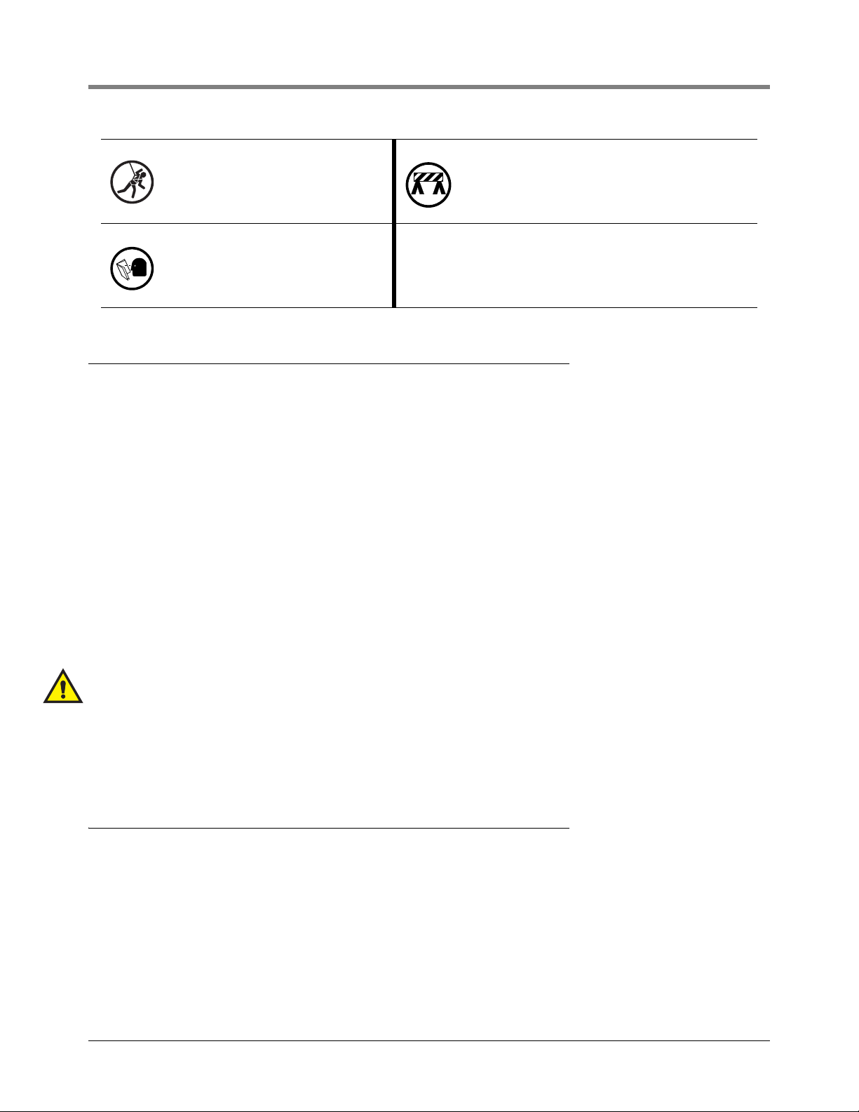
Safety Symbols
The following safety symbols may be used throughout this manual to alert you to important safety hazards and
precautions.
EXPLOSIVE
Fuels and their vapors are extremely explosive if ignited.
SLIPPERY
Curved metal tank surfaces can be extremely
slippery. Wear approved boots with slip
resistant soles.
POWER
To prevent ignition of flammable or combustible atmospheres, disconnect battery before
servicing.
4
FLAMMABLE
Fuels and their vapors are extremely flammable.
FALLING OBJECTS
Being struck by even small objects falling from tall structures can result in severe injury or death. Wear your hard
hat at all times when working alongside tall structures.
WAR N I NG
Heed the adjacent instructions to avoid damage to equipment, property, environment or personal injury.
Page 10
Introduction GENERAL PRECAUTIONS
SAFETY HARNESS
Injury or death resulting from falls while working on tall structures can be prevented by
wearing a 5-point harness that is tethered
securely by a shock absorbing lanyard to the
structure.
READ ALL RE LATED MANUALS
Knowledge of all related procedures before
you begin work is important. Read and
understand all manuals thoroughly. If you do
not understand a procedure, ask someone
who does.
SAFETY BARRICADES
Unauthorized people or vehicles in the work area are dangerous. Always use safety cones or barricades, safety
tape, and your vehicle to block the work area.
GENERAL PRECAUTIONS
Heed service markings: Opening or removing the console cover may expose you to electric shock. Servicing of
Veeder-Root equipment must be done by Veeder-Root authorized service contractors.
Use product with approved equipment: This product should be used only with Veeder-Root components identified
as suitable for use with the MAG-XL Flex Probe.
Use the correct external power sources: This product should be operated only from the type of power sources
indicated on the electrical ratings labels affixed to the components. If you are not sure of the type of power source
required, consult your Veeder-Root authorized service contractor.
MAG-XL Flex Probe cable length: The length of the cable from its exit point in the tank riser or tank fitting to the
transmitter cannot exceed 10 feet.
Wet or below grade installations: Installation of this equipment in wet or below grade locations requires that the
installer take steps to ensure that the equipment is mounted above the maximum water level.
The MAG-XL Flex Probe insertion length is critical to ordering and installing the correct probe into the correct tank.
An improper probe length could result in the probe weight coming in contact with the tank bottom resulting in
inaccurate fuel height measurement and possible probe damage.
CAUTION! THE TRANSMITTER WILL NOT FUNCTION PROPERLY IN WATER. ALSO, SUBMERSION
OF THE TRANSMITTER IN WATER CAN CAUSE PERMANENT DAMAGE TO THE INTERNAL
ELECTRONICS.
SPECIAL TOOLS REQUIRED
• Strap wrench (5-inch pipe capacity minimum) • Wire strippers • Tape measure
• Small blade screwdriver (max. blade width 3/32”) • T-10/T-15 Torx drivers • Thread sealant or PTFE tape
General AST Guidelines
Above ground storage tanks (AST’s) are an essential element in the distribution of petroleum products. Refer to
the following organizations for applicable standards associated with AST’s:
• American Petroleum Institute (API) – www.api.org
• National Fire Protection Association (NFPA) – www.nfpa.org
• Occupational Safety and Health Administration (OSHA) - www.osha.gov
• Petroleum Equipment Institute (PEI) – www.pei.org
• Steel Tank Institute (STI) – www.steeltank.com
• Underwriters Laboratories (UL) – www.ul.com
5
Page 11

Introduction AST Construction Safe Work Practices
The above organizations may not address requirements imposed by individual jurisdictions. Each site owner must
ensure that contractors performing the work be knowledgeable of all applicable regulations. It is fully the
responsibility of the contractor, or employee performing the work, to abide by any and all additional Federal, State, or
local laws, regulations and manufacturer’s requirements that apply to the specific work being done. It is also the
responsibility of each contractor to ensure that subcontractors abide by all applicable safety requirements.
Construction related activities are covered by OSHA regulation 29 CFR 1926.
AST tanks must be properly grounded according to local codes and regulations.
AST Construction Safe Work Practices
Department of Labor rules for construction work practices are governed by OSHA as described in the Code of
Federal Regulations (CFR):
Title 29, Volume 8, Part 1926 - Safety and Health Regulations for Construction. Copies of these regulations are
available from OSHA’s web site located at 29 CFR 1926 (http:\\www.osha.gov). Most maintenance and other
operations are covered by OSHA 29 CFR 1910 (General Industry) regulations. These documents highlight many of
the Federal OSHA requirements that may apply to maintenance and construction work in the retail petroleum/
convenience business, but there is much more in the regulations than can be covered here. Some relevant
subsections are listed:
1910.66: Appendix C - Powered platforms, Man lifts, and Vehicle-Mounted Work Platforms
1910.23: Walking - Working surfaces - Guarding
1910.132: Personal Protective Equipment
Additional important information is available in the API publication: Safe Work Practices for Contractors
Working at Retail Petroleum/Convenience Facilities, API Recommended Practice 1646 First Edition, August
2006, Product No. A16461. For more Information about API Publications, Programs and Services, go to
www.api.org. The requirements and recommended practices contained in this document are the minimum safety
procedures with which everyone shall comply while working at a retail petroleum/convenience facility.
In addition, a task specific Job Safety Analysis shall be completed before any work may begin.
Personal Protective Equipment
The list below contains recommended clothing and protective equipment. Additional items may be advisable
depending on the job’s particular circumstances:
• 5-point safety harness
• 6-foot maximum, shock absorbing lanyard (ensure that there will be a support structure on top of the tank to which
you can secure the lanyard)
•Hard hat
• Safety Glasses
• Safety Footwear (ANSI Z41)
•Long pants
• Gloves - leather for materials handling, cut-resistant for sharp materials
• A heavy canvas bag with handles to hold tools and pre-assembled parts
Before you Begin
The instructions in this manual assume:
• The top of the tank has a 4” riser pipe, threaded to receive the riser cap and ring or a 2-inch threaded pipe fitting
to receive a 2” x 3/4”Adapter/Reducer. The recommended length of the 4-inch riser pipe or 2-inch pipe fitting
6
Page 12

Introduction MAG-XL Flex Probe Operating Parameters
should be 10 inches, actual length dependent on probe insertion length.
IMPORTANT! The opening selected for the MAG-XL Flex Probe must be as far as possible from the
tank inlet piping.
• The TLS RF console and receiver are installed.
• The TLS console is installed. Note: the MAG-XL Flex Probe is only compatible with TLS Consoles installed with
Wireless 2 (2-Way) components supplied by V-R. The MAG-XL Flex Probe is for inventory only applications.
Leak detection is not available.
• You cannot mix Wireless 1 and Wireless 2 components on the same site or system. In each Wireless 2 System,
there is only one Receiver and one optional Repeater.
• The combination of the MAG-XL Flex Probe, XL Transmitter and the Battery Pack form an intrinsically safe
system and as such must be installed according to the instructions listed in this manual.
MAG-XL Flex Probe Operating Parameters
MAG-XL Flex Probe Limitations
Console Series
Maximum Limits
Probe Length in Feet 54.5 54.5 54.5 54.5 32
Probe Length in Inches 654 654 654 654 384
Probe Length in Centimeters
Tank Volume in Gallons 2,641,720 2,641,720 999,999 999,999 260,000
Tank Volume in Litres 9,999,999 9,999,999 3,785,408 3,785,408 984,207
Maximum Number of MagXL Probes per Console
Console Software Oldest
Compatible Version
TLS-450/TLS-XB TLS4/8601 TLS-350 TLS-300 TLS2
1,661 1,661 1,661 1,661 975
32 12 16 2 or 4 6
1C 1 22 22 1
MAG-XL Flex Probe Weights
Weight Part Number Pounds Kilograms
889001-008 4.56 2.07
889001-009 6.38 2.89
889001-010 10.02 4.55
889001-011 12.75 5.79
889001-012 14.58 6.61
889001-013 16.40 7.44
7
Page 13

Introduction National Electrical Code Compliance
National Electrical Code Compliance
The following information is for general reference and is not intended to replace recommended National Electric
Code (NEC) procedures. It is important for the installer to understand that electrical equipment and wiring located
in Class I, Division 1 and 2 installations shall comply with the latest appropriate articles found in the National
Electric Code (NFPA 70) and the Code for Motor Fuel Dispensing Facilities and Repair Garages (NFPA 30A), or
other local codes such as the CEC, Canadian Electrical Code.
AST tanks must be properly grounded according to NFPA 70 and applicable local codes and regulations.
MAG-XL FLEX PROBE WIRE LENGTH
Improper system operation could result in undetected potential environmental and health hazards if the MAG-XL
Flex Probe to TLS XL-Transmitter wire runs exceed 10 feet.
Veeder-Root Parts
• Veeder-Root MAG-XL Flex Probe, P/N 889111-XXX
• Veeder-Root Probe Components:
- 316 s.s. product float (2.05" dia., 0.54 sg, 350 psi), P/N 889001-001
- Weight Group (316 s.s. weight and 316 s.s. retaining pin)
• Veeder-Root MAG-XL Installation Kit (includes mounting hardware, transmitter and battery pack), P/N 858090202
• Optional 2-inch adapter/reducer (2” to 3/4”) kit (P/N 330020-666).
• Optional 4-inch riser cap and ring kit (P/N 330020-657).
Customer Supplied Parts
• Single-gang box from BELL outdoor, P/N 5321-0, or equivalent
• Single-gang blank cover from BELL outdoor, P/N 5173-0, or equivalent
• Galvanized threaded reducer bushing 3/4" to 1/2"
• Galvanized threaded 1/2” pipe, or 4” riser pipe, threaded to accept riser cap and ring
8
Page 14

Example Drawings
Example MAG-XL Flex Probe Site Layout Drawing
10
11
5
7
ALARM
WARNING
6
POWER
9
12
8
972-1.eps
13
2
1
4
3
2
1
Figure 1. Site drawing - example TLS RF wireless 2 system site layout – two Mag-XL Probes
LEGEND FOR NUMBERED BOXES I N Figure 1
To be installed in accordance with the National Electrical Code, NFPA
70 and the Code for Motor Fuel Dispensing Facilities and Repair Garages (NFPA 30A), or other local codes such as the CEC, Canadian
Electrical Code.
1. Battery Pack
2. TLS XL-Transmitter
3. Receiver
4. RS-485 Cable (Belden #3107A or equiv.)
5. TLS RF (Vm = 250 V)
6. Intrinsically safe wiring
7. TLS console (Vm = 250 V)
8. Conduit that enters power wiring knockouts
9. 120 or 230 Vac from power panel - separate branch circuits are
required for the TLS RF and TLS console.
10. Non-hazardous area
11. Hazardous area (Class I, Div. 1, Group D)
12. AST grounding cables and earth electrodes according to NFPA70
and local codes (ref. example in Figure 2).
13. Concrete tank pad.
9
Page 15

Example Drawings MAG-XL Flex Probe Dimensions
972-9.eps
5
7
6
3
4
2
1
10
11
9
8
MAG-XL Flex Probe Dimensions
Figure 2. MAG-XL Flex Probe parameters
LEGEND FOR NUMBERED BOXES I N Figure 2
1. Insertion measuring point for 2-inch pipe cap installations (top
of pipe cab to tank bottom). (see table below)
2. Insertion measuring point for 4-inch riser pipe installations
(top of riser pipe to tank bottom). Add 2 inches (50.8 mm) for
brass ring/and riser cap. (see table below)
3. Null zone - typical all probes (see table below)
4. Measured insertion Length (see table below for probe form
number to order - always order smaller probe if measured
insertion length falls between two probes in table.
5. Clearance off bottom (see table below)
6. Weight length (see table below)
7. Dead zone (see table below)
8. Tank grounding bracket
9. Grounding cable
10. Concrete tank pad
11. Earth grounded electrode with cable bracket
10
Page 16

Example Drawings MAG-XL Flex Probe Dimensions
972-12.eps
NULL
ZONE
DEAD
BAND
CLEAR-
ANCE
WEIGHT
GROUP
WEIGHT
LENGTH
NULL
ZONE
DEAD
BAND
CLEAR-
ANCE
WEIGHT
GROUP
WEIGHT
LENGTH
(INCHES) (FEET) (INCHES) (INCHES) (INCHES) FORM NO. (INCHES) (INCHES) (FE ET) (INCHES) (INCHES) (INCHES) FORM NO. (INCHES )
889111
02 4 144 12 ft. 12 6 889001-008 5 8 8 9 1 1 1
0 7 0 420 35 ft. 12 12 3 889001-010 11
889111
02 6 156
13 ft.
12 8 2
2
889001-009 7 8 8 9 1 1 1
0 7 1 426
35-1/2 ft.
12 12 3 889001-010 11
889111
02 8 168
14 ft.
12 8 2 889001-009 7 8 8 9 1 1 1
0 7 2 432
36 ft.
12 12 3 889001-010 11
889111
03 0 180 15 ft. 12 8 2 889001-009 7 8 8 9 1 1 1
0 7 3 438 36-1/2 ft. 12 15 4 889001-011 14
889111
03 2 192
16 ft.
12 8 2 889001-009 7 8 8 9 1 1 1
0 7 4 444
37 ft.
12 15 4 889001-011 14
889111
03 4 204 17 ft. 12 8 2 889001-009 7 8 8 9 1 1 1
0 7 5 450 37-1/2 ft. 12 15 4 889001-011 14
889111
03 6 216
18 ft.
12 8 2 889001-009 7 8 8 9 1 1 1
0 7 6 456
38 ft.
12 15 4 889001-011 14
889111
03 8 228 19 ft. 12 8 2 889001-009 7 8 8 9 1 1 1
0 7 7 462 38-1/2 ft. 12 15 4 889001-011 14
889111
04 0 240
20 ft.
12 8 2 889001-009 7 8 8 9 1 1 1
0 7 8 468
39 ft.
12 15 4 889001-011 14
889111
04 2 252 21 ft. 12 8 2 889001-009 7 8 8 9 1 1 1
0 7 9 474 39-1/2 ft. 12 15 4 889001-011 14
889111
04 4 264 22 ft. 12 8 2 889001-009 7 8 8 9 1 1 1
0 8 0 480 40 ft. 12 15 4 889001-011 14
889111
04 6 276 23 ft. 12 8 2 889001-009 7 8 8 9 1 1 1
0 8 1 486 40-1/2 ft. 12 15 4 889001-011 14
889111
04 8 288 24 ft. 12 8 2 889001-009 7 8 8 9 1 1 1
0 8 2 492 41 ft. 12 15 4 889001-011 14
889111
05 0 300 25 ft. 12 12 3 889001-010 11 8 8 9 1 1 1
0 8 3 498 41-1/2 ft. 12 15 4 889001-011 14
889111
05 2 312
26 ft.
12 12 3 889001-010 11 8 8 9 1 1 1
0 8 4 504
42 ft.
12 15 4 889001-011 14
889111
05 4 324
27 ft.
12 12 3 889001-010 11 8 8 9 1 1 1
0 8 5 510
42-1/2 ft.
12 15 4 889001-011 14
889111
05 6 336 28 ft. 12 12 3 889001-010 11 8 8 9 1 1 1
0 8 6 516 43 ft. 12 15 4 889001-011 14
889111
05 8 348 29 ft. 12 12 3 889001-010 11 8 8 9 1 1 1
0 8 8 528 44 ft. 12 15 4 889001-011 14
889111
05 9 354
29-1/2 ft.
12 12 3 889001-010 11 8 8 9 1 1 1
0 9 0 540
45 ft.
12 15 4 889001-011 14
889111
06 0 360 30 ft. 12 12 3 889001-010 11 8 8 9 1 1 1
0 9 2 552 46 ft. 12 15 4 889001-011 14
889111
06 1 366
30-1/2 ft.
12 12 3 889001-010 11 8 8 9 1 1 1
0 9 4 564
47 ft.
12 15 4 889001-011 14
889111
06 2 372
31 ft.
12 12 3 889001-010 11 8 8 9 1 1 1
0 9 6 576
48 ft.
12 15 4 889001-011 14
889111
06 3 378 31-1/2 ft. 12 12 3 889001-010 11 8 8 9 1 1 1
0 9 8 588 49 ft. 12 15 4 889001-011 14
889111
06 4 384 32 ft. 12 12 3 889001-010 11 8 8 9 1 1 1
1 0 0 600 50 ft. 12 15 4 889001-011 14
889111
06 5 390 32.5 ft. 12 12 3 889001-010 11 8 8 9 1 1 1
1 0 2 612 51 ft. 12 17 5 889001-012 16
889111
06 6 396 33 ft. 12 12 3 889001-010 11 8 8 9 1 1 1
1 0 4 624 52 ft. 12 17 5 889001-012 16
889111
06 7 402 33.5 ft. 12 12 3 889001-010 11 8 8 9 1 1 1
1 0 6 636 53 ft. 12 17 5 889001-012 16
889111
06 8 408
34 ft.
12 12 3 889001-010 11 8 8 9 1 1 1
1 0 8 648
54 ft.
12 17 5 889001-012 16
889111
06 9 414
34.5 ft.
12 12 3 889001-010 11 8 8 9 1 1 1
1 0 9 654
54-1/2 ft.
12 17 5 889001-012 16
TOP MOUNTED DIGITAL MAG PROBE
INVENTORY ONLY - NO WATER DETECTION
MEASURED
INSERTION
LENGTH
FORM NO.
FORM NO.
MAG - XL
MEASURED
INSERTION
LENGTH
MAG - XL
7
5
6
347
5
6
34
You can determine the insertion length of a Mag-XL probe from its form number. Just multiply the form number suffix (-XXX) by 6 inches
to get the insertion length. For example, the first probe in the table, 889111-024, has an insertion length of 144 inches (024 x 6 = 144").
1 1
1
Table 1. MAG-XL Flex Probe Specifications
11
Page 17

Example Drawings Example MAG-XL Flex Probe Installation in Tank Manway
Example MAG-XL Flex Probe Installation in Tank Manway
6
5
4
3
2
1
7
8
9
972-2b.eps
Figure 3. MAG-XL Flex Probe installation with riser pipe, top mounted in tank manway
LEGEND FOR NUMBERED BOXES I N Figure 3
1. Battery cable to MAG-XL transmitter
2. Battery pack
3. Brass 4” riser cap and ring (optional)
4. Weatherproof junction box (customer supplied)
5. 1/2” NPT galv. nipple and 3/4” to 1/2” reducing bushing (customer supplied)
10
6. 1/2” NPT Brass adapter
7. TLS XL-Transmitter
8. 4” riser (Customer supplied - recommended riser length of 10”,
actual length dependent on probe insertion length)
9. MAG-XL Flex Probe Weight set a minimum distance above bottom of tank (see Table 1).
10. Tank grounding (ref items 8 - 11 in Figure 2).
12
Page 18

Example Drawings Example MAG-XL Flex Probe Installation in Existing Tank Opening
972-2c.eps
8
4
5
6
2
1
3
7
9
Example MAG-XL Flex Probe Installation in Existing Tank Opening
Figure 4. MAG-XL Flex Probe installation without riser pipe, top mounted in existing tank opening
LEGEND FOR NUMBERED BOXES I N Figure 3
1. Pipe cap with 3/4” NPT threaded opening (customer supplied)
2. Weatherproof junction box with 3/4” to 1/2” reducing bushing
in top opening (customer supplied)
3. Battery pack
4. 1/2” conduit, 6” minimum length, threaded both ends (customer supplied)
5. 1/2” NPT Brass adapter
6. TLS XL-Transmitter
7. Battery cable
8. MAG-XL Flex Probe Weight set a minimum distance above bottom of tank (see Table 1).
9. Tank grounding (ref items 8 - 11 in Figure 2).
13
Page 19

Example Drawings Component Dimensions
972-6.eps
1
2
.513
(13.03 mm)
W2
3.22
(81.79 mm)
3.52
(89.41 mm)
3.25
(82.55 mm)
3.81
(96.77 mm)
1.97
(50.03 mm)
10.51
(266.9 mm)
3.52
(89.41 mm)
3.22
(81.79 mm)
Component Dimensions
Dimensions of the TLS XL-Transmitter and battery housing are shown in Figure 5.
Figure 5. Wireless component dimensions
1. TLS XL-Transmitter dimensions 2. Battery housing dimensions
LEGEND FOR NUMBERED BOXES I N Figure 5
14
Page 20

MAG-XL Flex Probe Installation
Pre-Installation Component Setup and Functional Check
Follow the steps in the ‘Pre-Installation Component Setup and Functional Check’ section of the TLS RF Wireless 2
System (W2) Installation and Maintenance Guide (577013-964) to verify the Wireless System’s component
functionality.
Assemble the Battery Pack Mounting Bracket
PROBE INSTALLATION - MANWAY 4-INCH RISER PIPE
1. Connect the two 4-inch conduit hangers (item 1) from the installation kit to the battery mounting bracket (item
4) as shown in Figure 6.
2. Insert the bolt/nut pairs (items 2 and 3 in the figure) in each hanger as shown, but do not tighten.
3. Tighten the two bolt/nut pairs (items 2 and 5 in the figure) securing the mounting bracket to the conduit hangers.
4. Get the customer supplied outdoor junction box. Get the customer supplied 3/4” x 1/2” reducing bushing.
Apply pipe thread sealant or PTFE tape to its threads and screw it into the top threaded opening of the junction box until tight.
5. Get the 1/2” nipple from the probe installation kit. Apply pipe thread sealant or PTFE tape to its threads and
screw it in the reducing bushing until tight.
6. Get the 1/2” brass hex adapter from the probe installation kit and after orienting the embossed arrow down,
apply pipe thread sealant or PTFE tape to its threads and screw it onto the 1/2” nipple until tight.
7. Take the battery support assembly, the junction box/conduit assembly and the transmitter to the top of the tank
for final assembly.
PROBE INSTALLATION - TOP OF TANK 2-INCH PIPE OPENING
1. Connect the two 2-inch conduit hangers (item 1) from the installation kit to the battery mounting bracket (item
4) as shown in Figure 6.
2. Insert the bolt/nut pairs (items 2 and 3 in the figure) in each hanger as shown, but do not tighten.
3. Tighten the two bolt/nut pairs (items 2 and 5 in the figure) securing the mounting bracket to the conduit hangers.
15
Page 21

MAG-XL Flex Probe Installation Unpack the MAG-XL Flex Probe
972-7.eps
2
3
5
4
3
1
Figure 6. Attaching conduit hangers to battery mounting bracket
LEGEND FOR NUMBERED BOXES I N Figure 6
1. 2-inch or 4-inch conduit hanger [as required] - 2 places
2. 1/4 x 20 hex head nut - 4 places
3. 1/4 x 20 x 1.25” hex head bolt - 2 places
4. Battery pack support bracket
5. 1/4 x 20 x 0.5” hex head bolt - 2 places
4. Get the customer supplied outdoor junction box and the customer supplied 3/4” x 1/2” reducing bushing and
screw it into the top threaded opening of the junction box until tight.
5. Get the customer supplied length of 1/2” conduit and screw it in the reducing bushing until tight.
6. Get the 1/2” brass hex adapter from the probe installation kit and after orienting the embossed arrow down,
screw it onto the other end of the 1/2” conduit until it is tight.
7. Take the battery support assembly, the junction box/conduit assembly and the transmitter to the top of the tank
for final assembly on the 2-inch tank fitting.
Unpack the MAG-XL Flex Probe
CAUTION!
• DO NOT CUT THE TIE WRAPS that hold the coiled MAG-XL Flex Probe together before installation.
• DO NOT BEND THE TOP 2 FEET OF THE MAG-XL Flex Probe. The top of the MAG-XL Flex Probe has
electronic components inside of the tube and must remain straight (see Figure 7).
• ALWAYS KEEP THE COILS PARALLEL. When the tie wraps are removed, do not lift one coil separately from
the other coils. Never twist one coil 90 degrees from the other coils. See Figure 8.
16
Page 22

MAG-XL Flex Probe Installation Assemble the MAG-XL Flex Probe Components
972-18.eps
• DO NOT ASSEMBLE THE WEIGHT AND FLOATS ON THE MAG-XL Flex Probe UNTIL READY TO BE
INSTALLED IN THE RISER. Carry the parts to the top of the tank before assembling. Do not unwrap the MAGXL Flex Probe until ready to install.
• DO NOT TWIST THE MAG-XL Flex Probe DURING INSTALLATION. Always keep the coils of the MAG-XL Flex
Probe parallel as you “unroll” it into the tank.
• DO NOT LET THE COIL BECOME LESS THAN 44.50” IN DIAMETER WHILE UNCOILING.
Figure 7. Do not bend top 2 feet of probe Figure 8. Do not twist one coil 90° from the others
Assemble the MAG-XL Flex Probe Components
CAUTION! the following procedures are conducted on top of the tank. Observe all safety
precautions for working on tall and possibly slippery structures.
PROBE INSTALLATION - MANWAY 4-INCH RISER PIPE
1. Cut ONLY the tie wrap at the bottom end of the probe’s tube (the end with a hole through the tube) - not the
end with the two wires coming out of the threaded plug. Leave the other tie wraps intact. This will prevent the
coil from unwrapping before installation.
2. Get the optional 4-inch Riser Cap installation kit.
3. Slide the components (see Figure 9) onto the bottom end of the tube in the following order:
• 4-inch riser cap (insert end of probe through the 3/4” tapped hole in the riser cap) (item 1)
• Product Float (item 2)
17
Page 23

MAG-XL Flex Probe Installation Assemble the MAG-XL Flex Probe Components
1 2 3 4
1 2 3 4
• Stainless steel weight which holds the probe straight (item 3)
Figure 9. MAG-XL Flex Probe components - manway install
4. Get the stainless steel pin from the kit (item 4 in the above figure). Lift up the stainless steel weight (and other
components) and push the pin through the hole in the bottom end of the probe tube leaving equal lengths of
the pin on each side of the tube (this will secure the above components on the probe’s tube).
PROBE INSTALLATION - TOP OF TANK 2-INCH PIPE FITTING
1. Cut ONLY the tie wrap at the bottom end of the probe’s tube (the end with a hole through the tube) - not the
end with the two wires coming out of the threaded plug. Leave the other tie wraps intact. This will prevent the
coil from unwrapping before installation.
2. Get the Optional 2-inch Adapter/Reducer (2” to 3/4”) kit.
3. Slide the components (see Figure 9) onto the bottom end of the tube in the following order:
• 2” to 3/4” Adapter/Reducer (item 1)
• Product Float (item 2)
• Stainless steel weight which holds the probe straight (item 3)
Figure 10. MAG-XL Flex Probe components - pipe fitting install
4. Get the stainless steel pin from the probe kit (item 4 in the above figure). Lift up the stainless steel weight (and
other components) and push the pin through the hole in the bottom end of the probe tube leaving equal
lengths of the pin on each side of the tube (this will secure the above components on the probe’s tube).
18
Page 24

MAG-XL Flex Probe Installation Install the MAG-XL Flex Probe Assembly
972-16.eps
✓
Install the MAG-XL Flex Probe Assembly
IMPORTANT! Installing the MAG-XL Flex Probe requires two people.
PROBE INSTALLATION - MANWAY 4-INCH RISER PIPE
1. Slide the conduit hangers of the battery support assembly down over the 4-inch riser pipe and let it rest
against the tank flange for now.
2. Screw the brass ring (from the brass riser cap and ring kit) onto the 4” riser and tighten with strap wrench.
3. When lifting the coiled probe prior to installation, the stainless steel weight must always hang straight down
(see Figure 11). DO NOT BEND THE TUBING. Do not let the radius of the coiled probe become less than
23” or the brass tube may kink. KINKING THE PROBE IS NOT COVERED BY WARRANTY!
CAUTION! Do not let one person lower the probe into the tank to avoid bends in the tube or twists
to the coils! (see Figure 12).
4. Using two people as shown in Figure 11, lower the weight into the tank. Do not drop the weight the full length
of the probe or it may damage the end of the probe. Slowly feed the probe into the riser, cutting the remaining
tie wraps, one by one, as you go. Do not cut all of the tie wraps at once. They have been sequentially marked.
Start with tie wrap number 1 at the bottom end of the probe.
5. When all but the last couple of feet of the probe tubing is in the tank, one person must continue to hold the
CAUTION: One person cannot lower probe into tank correctly!
972-17.eps
Figure 11. Correctly lowering probe into
tank
top of the probe tubing while the second person, applies pipe thread sealant or PTFE tape to threads of the
threaded fitting at the top of the probe and then screws the probe fitting into the 4” brass riser cap. The entire
probe assembly is supported by this connection, so the probe’s top fitting must be tightened securely in the
riser cap.
Figure 12. Incorrectly lowering probe into tank
19
Page 25

MAG-XL Flex Probe Installation Installing the TLS XL-Transmitter
6. Holding the brass cap, not the probe cable, lower the brass riser cap (and probe) onto the brass ring already
on the riser. Raise the two cap locking levers into place on top of the cap.
7. Raise the conduit hangers up the 4-inch riser pipe until the top one is several inches below the cap and brass
ring. Tighten the bolts (items 3 and 6 in the Figure 6) that hold the mounting bracket in place.
8. Lower the battery pack into its support bracket (see Figure 13). Do not connect battery cable to battery pack
at this time.
PROBE INSTALLATION - TOP OF TANK 2-INCH PIPE FITTING
IMPORTANT! Installing the MAG-XL Flex Probe requires two people.
1. When lifting the coiled probe prior to installation, the stainless steel weight must always hang straight down
(see Figure 11). DO NOT BEND THE TUBING. Do not let the radius of the coiled probe become less than
23” or the brass tube may kink. KINKING THE PROBE IS NOT COVERED BY WARRANTY!
CAUTION! Do not let one person lower the probe into the tank to avoid bends in the tube or twists
to the coils! (see Figure 12).
2. Using two people as shown in Figure 11, lower the weight into the tank. Do not drop the weight the full length
of the probe or it may damage the end of the probe. Slowly feed the probe into the riser, cutting the remaining
tie wraps, one by one, as you go. Do not cut all of the tie wraps at once. They have been sequentially marked.
Start with tie wrap number 1 at the bottom end of the probe.
3. When all but the last couple of feet of the probe tubing is in the tank, one person must continue to hold the
top of the probe tubing while the second person applies pipe thread sealant or PTFE tape to threads of the
threaded fitting at the top of the probe and then screws the probe fitting into the 3/4” end of the Adapter/Reducer. The entire probe assembly is supported by this connection, so the probe’s top fitting must be tightened securely in the Adapter/Reducer.
4. Apply pipe thread sealant or PTFE tape to the threads of the 2-inch tank fitting. Holding the Adapter/Reducer,
not the probe cable, lower the Adapter/Reducer (and probe) onto the tank fitting and screw on the Adapter/
Reducer and tighten it using the strap wrench.
Installing the TLS XL-Transmitter
TLS XL-TRANSMITTER INSTALLATION - MANWAY 4-INCH RISER PIPE (ref. Figure 13)
1. Make sure the battery/dc power cable is not connected to the battery pack or dc power source at this time.
WARNING! To prevent ignition of flammable or combustible atmosphere the battery cable must
be disconnected from the battery pack.
2. Get the pre-assembled junction box/conduit assembly. Remove the cover of the junction box. Feed the probe
cable into the bottom threaded opening of the junction box/conduit and screw the junction box/conduit onto
the probe’s threaded fitting in the top of the riser cap until tight. Coil up the probe cable and hang it out of the
way.
3. Feed the end of the cable up through the reducing bushing, the 1/2” nipple and out the 1/2” brass hex adapter. Coil up about 12 inches of cable in the junction box (for a service loop) and then replace and tighten the
cover on the junction box.
4. Get the TLS XL-Transmitter. Looking at the cover of the transmitter, notice that one of the cord grips is labelled to receive the probe cable and the other to receive the battery pack/dc power cable. Remove the nut
from the probe cable cord grip and notice that the rubber bushing is marked with a white dot (the bushing for
the battery cable has a larger opening and is not marked). Using a T-10 Torx driver, remove the cover of the
20
Page 26

MAG-XL Flex Probe Installation Installing the TLS XL-Transmitter
transmitter. Push the end of the probe cable through the probe cable cord grip bushing and into the transmitter. Pull the excess cable through the cord grip bushing as you lower the transmitter down onto the 1/2” hex
brass adapter. Screw the transmitter into the top of the 1/2” brass hex adapter until tight.
5. Proceed to “Connecting MAG-XL Flex Probe Wiring” on page 23.
TLS XL-TRANSMITTER INSTALLATION - TOP OF TANK 2-INCH PIPE FITTING (ref. Figure 14)
1. Make sure the battery/dc power cable is not connected to the battery pack or dc power source at this time.
WARNING! To prevent ignition of flammable or combustible atmosphere the battery cable must
be disconnected from the battery pack.
2. Get the pre-assembled junction box/conduit assembly. Remove the cover of the junction box. Feed the probe
cable into the bottom threaded opening of the junction box/conduit and screw the junction box/conduit onto
the probe’s threaded fitting in the top of the riser cap until tight. Coil up the probe cable and hang it out of the
way. Replace the cover on the junction box and screw it on tight.
3. Feed the end of the cable up through the reducing bushing, the 1/2” nipple and out the 1/2” brass hex adapter. Coil up about 12 inches of cable in the junction box (for a service loop) and then replace and tighten the
cover on the junction box.
4. Get the TLS XL-Transmitter. Looking at the cover of the transmitter, notice that one of the cord grips is labelled to receive the probe cable and the other to receive the battery pack/dc power cable. Remove the nut
from the probe cable cord grip and notice that the rubber bushing is marked with a white dot (the bushing for
the battery cable has a larger opening and is not marked). Using a T-10 Torx driver, remove the cover of the
transmitter. Push the end of the probe cable through the probe cable cord grip bushing and into the transmitter. Pull the excess cable through the cord grip bushing as you lower the transmitter down onto the 1/2” hex
brass adapter. Screw the transmitter into the top of the 1/2” brass hex adapter until tight.
5. Proceed to “Connecting MAG-XL Flex Probe Wiring” on page 23.
21
Page 27

MAG-XL Flex Probe Installation Installing the TLS XL-Transmitter
6
3
4
1
2
7
972-4.eps
8
5
9
CAUTION! TIGHTEN
CORD GRIPS TO PREVENT
WATER INGRESS!
Figure 13. Installing TLS XL-Transmitter - manway riser pipe
1. Battery pack
2. 4” brass riser cap
3. Single-gang box from BELL outdoor, P/N 5321-0, or equivalent
(customer supplied)
4. 1/2” galvanized nipple
5. 1/2” brass hex adapter
LEGEND FOR NUMBERED BOXES IN Figure 13
6. TLS XL-Transmitter
7. 3/4” x 1/2” NPT reducing bushing (customer supplied)
8. 3/4” NPT probe threaded fitting
9. 4” riser, recommended riser length of 10”, actual length dependent on probe insertion length (customer supplied)
22
Page 28

MAG-XL Flex Probe Installation Connecting MAG-XL Flex Probe Wiring
6
3
4
1
2
7
8
972-11.eps
5
CAUTION! TIGHTEN
CORD GRIPS TO PREVENT
WATER INGRESS!
Figure 14. Installing TLS XL-Transmitter - tank 2-inch pipe fitting
LEGEND FOR NUMBERED BOXES IN Figure 13
1. 2” - 3/4” Adapter/Reducer
2. Single-gang box from BELL outdoor, P/N 5321-0, or equivalent
with 3/4” x 1/2” NPT reducing bushing (customer supplied)
3. Battery pack
4. 1/2” conduit, min. 6” length (customer supplied)
Connecting MAG-XL Flex Probe Wiring
1. Strip back the probe cable jacket and wires as shown in Figure 16.
2. Attach the three MAG-XL Flex Probe cable wires to the PROBE terminal block (red to P, white to D and black
to G) (see item 1 in Figure 16).
3. Making sure the battery cable is not connected to the battery pack, attach the battery pack/dc power cable to
the BATTERY terminal block (white to +IN and black to -IN) as shown in Figure 16.
Hand tighten the battery cable entry cord grip nut to prevent water entry!
5. 1/2” brass hex adapter
6. TLS XL-Transmitter
7. Probe cable
8. 3/4” NPT probe threaded fitting
23
Page 29

MAG-XL Flex Probe Installation Connecting MAG-XL Flex Probe Wiring
972-5.eps
5
Battery
Connection
CAUTION! TIGHTEN
HEX ADAPTER AND
CORD GRIP TO PREVENT
WATER INGRESS!
2
1
3
4
S1
S2
+IN
-IN
BATTERY
PROBE
PDG
1
1/4"
1. Strip back cable and wire jackets the amount shown.
2. Use a screwdriver with the proper blade width.
1-1/4"
Figure 15. Connecting input wiring to transmitter terminal blocks
LEGEND FOR NUMBERED BOXES IN Figure 15
2 3
3/32" (2.4mm)
964-23.eps
3. Wires must be tight in terminals!
1. MAG-XL Flex Probe cable connections:
•Red to P (power)
•White to D (data)
•Black to G (ground)
2. S1 DIP switch
3. S2 DIP switch
Figure 16. Connecting probe and battery pack cables to the TLS XL-Transmitter
LEGEND FOR NUMBERED BOXES IN Figure 16
4. Battery power cable connections -– observe polarity:
• +IN (White)
•–IN (Black)
5. Red Battery ID label attached to both ends of battery cable
Pay close attention to the polarity of the battery input
connections. Reversing the connections can cause damage to the TLS RF.
24
Page 30

MAG-XL Flex Probe Installation Connecting MAG-XL Flex Probe Wiring
4. To assure a water-tight seal between the cover and the enclosure, follow these steps:
a. Insert the four cover screws through the cover and then press on the retaining washers to hold the screws
in place.
b. Make sure that the cover gasket is free of dirt and debris on both sides of the gasket and that the inside of
the cover is clean in the gasket area.
c. Position the gasket into the cover groove, assuring that it is pressed fully into the groove and sitting
completely flat.
d. Assemble the cover onto the enclosure, tightening the screws in a couple of turns each. Using an
alternating ‘X’ pattern, continue to tighten the screws until they are all tight.
5. If you haven’t done so already, attach the red battery ID labels from the installation kit onto the power cable
below the power cord grip and at the battery pack connector.
6. Follow the steps in the ‘Site Startup Procedure section of the TLS RF Wireless 2 System (W2) Installation
and Maintenance Guide (577013-964) BEFORE
attaching the battery cable to the battery pack connector.
25
Page 31

TLS Console Setup for MAG-XL Flex Probe
With the TLS RF System powered on and the Mag-XL Probes recognized by the TLS Console, begin the console
setup for each Mag-XL Probe(s). Figure 17 lists in-tank setup examples for a Mag-XL Probe.
Height Reading Adjustment
A MAG-XL Flex Probe cannot measure fuel on the bottom of the tank as the minimum height reading is between 7
and 22 inches. Also, depending on the length of the MAG-XL Flex Probe, a clearance distance between the probe
and tank bottom is required to compensate for the thermal expansion of the probe. To account for the loss of
clearance height, the fuel height reading of the MAG-XL Flex Probe must be adjusted on the TLS Console.
Use a tape measure to determine the height of fuel inside the tank. On the TLS Console enter a probe offset value
to match the height of the fuel float on the MAG-XL Flex Probe to the fuel height inside the tank. The probe offset
is typically a number (in inches) greater than, or equal to, the clearance between the end of the probe and the
bottom of the tank.
Setting the offset value for a 20’ MAG-XL Flex Probe:
• Mechanical Gage Reading 187 inches
• MAG-XL Flex Probe on TLS 181 inches
• Set the TLS probe offset 6.0 inches (positive 6” difference)
• After programming the offset value into the TLS Console, the respective fuel height now matches the
mechanical gage reading.
26
Page 32

TLS Console Setup for MAG-XL Flex Probe Height Reading Adjustment
TLS Console Setup
Example of In-Tank Setup for MAG-XL Flex Probes used with TLS Console s
Parameter
Value Notes
PRODUCT LABEL T1: Fuel Oil Customer to specify product name
PRODUCT CODE: 1 Code used by the point-of-sale terminal
THERMAL COEFF: 0.00047 Coefficient value depends on product ty pe
TANK DIAMETER: 432
Enter the internal tank height not diameter
1
TANK PROFILE:
LINEAR2Setting for Vertic al Tanks
FULL VOLUME : 115,925
Ex: 115,925 gallon t ank capac ity
1
METER DATA PRESENT: NO Not Us ed for MAG-XL Flex Probe Setup
CAL UPDATE: IMMEDIATE Leave at t he default setting
FLOAT SIZE: 4.0 IN. Always set to 4" for MAG-XL Flex Probes
WATER W A RNING: 2.0 Not Used for MAG-XL Flex Probe S etup
HIGH WATER LIMIT: 4.0 Not Used for MAG-XL Flex Probe Setup
MAX or LABEL V OL: 110,000 Max imum safe working volume
OVERFILL LIMIT: 90% Maximum volume warning during a delivery
HIGH PRODUCT: 95% Maximum volume alarm setting
DELIVERY LIMIT: 20%
10%
Low tank volume warning
LOW PRODUCT: Set to a level higher t han t he discharge port
LEAK ALARM LIMIT: 0 Not Used for MAG-XL Flex Probe Setup
SUDDEN LOSS LIMIT: 0 Not Used for MAG-XL Flex Probe Setup
TANK TILT:
0
2
Not Used for Mag-XL Probe Setup
PROBE OFFSET:
4
2
Distance between probe and tank bottom
1
T1: SIPHON MANIFOLDED 0 Not Used for MAG-XL Flex Probe Setup
T1: LINE MANIFOLDED 0 Not Used for MAG-XL Flex Probe Setup
Multiple Leak Testing Parameters Not Used Not Used for MAG-XL Flex Probe Setup
DELIVERY DELAY: 01 Delay time in minutes (up to 99)
PUMP THRES HOLD: Not Used Not Used for MAG-XL Flex Probe Setup
Press STEP to set additional t anks Repeat above in-tank s etup for each probe
Values shown above are for reference only
1
For further details on how to calculate this value, refere nce the a ppropria te
explanati ons included in this manual.
2
Setting this value correctly is critical to product performance.
3
3
3
3
3
3
See TLS Limit Calculations on next page.
Figure 17. In-tank setup for TLS Consoles used with MAG-XL Flex Probes
972-14.eps
27
Page 33

TLS Console Setup for MAG-XL Flex Probe TLS Limit Calculations
TLS Limit Calculations
To calculate the gallons per inch (GPI) for each tank, install the MAG-XL Flex Probe and call for a delivery. Record
the current fuel height at the TLS, make the delivery and after waiting a few minutes for the tank level to stabilize
take a second fuel height measurement. Divide the delivered volume in gallons by the recorded fuel height change
in inches to get your tank’s gallons per inch value.
LIMIT CALCULATION EXAMPLE
1. Fuel height reading before the delivery = 48 inches. Fuel height reading after the delivery = 72 inches
2. Ticketed delivered fuel amount was 6050 gallons.
3. Difference in fuel height recordings = 24 inches.
4. Divide the delivered fuel volume by the fuel height change = 6050/24 = 252.08 gallons per inch (GPI).
5. If the tank is 30 feet high, then 30 x 12 inches per foot = 360 (the tank’s height in inches) then the 30-foot
tank’s full volume would be 252.083 GPI x 360 inches = 90750 gallons.
6. Also, if applicable, you must consider the 12” null zone at the top of the probe. If the probe riser pipe is longer
than 9 inches, the null zone can be ignored. If the probe riser is 9 inches or less subtract the riser length from
12” to calculate the non-working top section of the probe. For example, you have a 5-inch riser: 12” – 5” = 7”
and 7” X 252.08 gallons is 1765 gallons that cannot be measured by the MAG-XL Flex Probe. This reduces
the 100% or full volume to: 90,750 – 1765 = 88,985 gallons.
7. To calculate the various alarm limits using the above example 30 foot tank having a 5-inch riser and a discharge port that is 24 inches from the bottom of the tank (ref Figure ):
• 100% 88,895 gallons Full Volume
• 95% 84,450 gallons High Product
• 90% 80,005 gallons Overfill Limit
• 20% 17,779 gallons Delivery Limit
• 10% 8889 gallons Low Product
• Minimum Volume is the volume that is below the bottom of the discharge port (calculated by multiplying
the distance from the tank bottom to the bottom of the discharge port by the GPI. In this example, 24” X
252.08 GAL. = 6050 gallons).
28
Page 34

TLS Console Setup for MAG-XL Flex Probe TLS Limit Calculations
1
100%
2
3
95%
4
90%
5
20%
6
10%
7
8
9
Figure 18. Alarm Limit Settings
LEGEND FOR NUMBERED BOXES IN Figure 18
1. Probe’s null zone
2. Full or Max Volume Limit - 100% (to top of tank or to beginning
of probe’s null zone as applicable)
3. High Product limit - 95% of full volume
4. Overfill limit - 90% of full volume
5. Delivery limit - 20% of full volume
972-15.eps
6. Low Product Limit - 10% of full volume
7. Bottom of discharge port
8. Minimum volume (distance from tank bottom to bottom of discharge port multiplied by tank’s gallon per inch value)
9. Concrete tank pad
29
Page 35

TLS Console Setup for MAG-XL Flex Probe Vertical Tank Volume Calibration
Into the Tank Deliveries
Into the Tank Deliveries
Vertical Tank Volume Calibration
Enter the full tank volume based on the volume specification provided by the tank manufacturer referred to as the
nominal tank volume in the following examples. If a vertical tank’s volume to height ratio is known, use the most
precise full tank volume available and enter that volume into the TLS Console.
Over time, calibrate the tank’s volume by comparing volume from each delivery ticket to the delivery volumes
recorded by the TLS Console. Use several deliveries to calculate the average volume error (as a percentage of the
total volume). The calculated tank volume is an adjustment to the full tank volume based an average of the delivery
volumes. On the TLS Console, adjust the full tank volume to compensate for this error as demonstrated in
examples 1 and 2 in Figure 19 below using the calculated tank volume as the new full tank volume.
Example 1 - Manual Tank Calibration for a Positive Error
Nominal Tank Volume: 125,000
Calculated Tank Volume: 115,925
D1 D2 D3 D4 D5
Metered Volume Delivered (Input) 2,774 3,812 2,344 2,802 1,699
Delivery Volume Reported by TLS 2,985 4,062 2,525 2,981 1,835
Volume Difference (positive error) 7.61% 6.55% 7.73% 6.39% 8.00%
Average of the Volume Difference 7.26% (125,000 x .0726 = 9,075)
Adjust the tank volume downward by this Difference: Nominal Tank Volume minus 9,075
Calculated Tank Volume 125,000 - 9,075 = 115,925
Example 2 - Manual Tank Calibration for a Negative Error
Nominal Tank Volume: 500,000
Calculated Tank Volume: 547,050
D1 D2 D3 D4 D5
Metered Volume Delivered (Input) 4,772 3,650 5,391 4,446 4,822
Delivery Volume Reported by TLS 4,363 3,259 4,923 3,980 4,408
Volume Difference (negative error) -8.58% -10.71% -8.68% -10.49% -8.59%
Average of the Volume Difference -9.41% (500,000 x .0941 = 47,050)
Adjust the tank volume upward by this Difference: Nominal Tank Volume plus 47,050
Calculated Tank Volume 500,000 + 47,050 = 547,050
Figure 19. Volume calibration examples
972-14.eps
30
Page 36

MAG-XL Flex Probe Troubleshooting
The following diagnostics are for the MAG-XL Flex Probe. For wireless troubleshooting and/or additional probe
troubleshooting information, refer to the TLS RF Wireless 2 System (W2) Installation and Maintenance Guide, part
number 577013-964.
Troubleshooting
Use the TLS Console to check the probe height and temperature readings. If the probe is communicating properly
with the console but either the height or temperature are reading 999's, check for the symptoms listed below. If
the Console is receiving data, the product height level is equal to the position of the float on the probe tube. A
level reading error will occur if the offset (Mag Probe Offset) for the probe is incorrect, see the previous
description for making height reading adjustments.
If the probe is installed in an empty tank, the product float will be resting on the weight at the bottom of the tank. In
an empty tank, the product level height reading may vary because of temperature changes even though there is no
liquid product in the tank. The probe does not measure the product level until the float becomes buoyant.
PROBE OUT OR NO PROBE DETECTED
1. Check the probe part number to be sure the correct probe is installed.
2. Be sure that each TLS RF box and the TLS Console have a good Earth Ground.
3. Using the appropriate torx driver remove the cover of the suspect transmitter. Note that water should not be
present inside the transmitter enclosure.
4. Check the 3-conductor wiring between the transmitter and the probe to ensure that each connection is secured in the appropriate terminal (ref. Figure 16 on page 24). Verify that all wire connections are secure and
free of shorts.
5. Check the input voltage from the battery going into the TLS XL-Transmitter, it should measure between 2.4
and 3.8 volts.
6. Check that the two cable cord grips are tight.
7. Replace the transmitter cover and the torque the securing screws to 10 inch-pounds.
8. If necessary, refer to the TLS RF Wireless 2 System (W2) Installation and Maintenance Guide, part number
577013-964.
INCORRECT PRODUCT HEIGHT READING
Product Height Reading Error: 999.99
The product float magnet is in the null zone (ref. Table 1 on page 11) or the probe is malfunctioning.
Temperature Reading Error: -99.9
The working temperature range of the probe is -40°F through +122°F.
A MAG-XL Flex Probe is designed to work with one float only, make sure the float is installed and moving freely on
the probe tube. If the product float is located in either the dead band (bottom) or the null zone (top) of the probe,
the product height on the TLS Console will be incorrect.
31
Page 37

MAG-XL Flex Probe Troubleshooting Troubleshooting
Once installed, the MAG-XL Flex Probe must not contact any other object, such as: the bottom of the tank,
ladders, the side wall or piping.
Electrical noise or magnetic interference can cause reading errors. Also, physically inspect the probe tube for kinks
or bends as the surface of the tube must be smooth and straight. Contact Veeder-Root Technical Support for
assistance with these issues.
32
Page 38

For technical support, sales or
other assistance, please visit:
www.veeder.com
 Loading...