

Page 1

Site Prep & Installation Manual
TLS RF Wireless System
Manual No: 577013-839 ● Revision: L
Page 2

Notice
Veeder-Root makes no warranty of any kind with regard to this publication, including, but not limited to, the implied warranties of
merchantability and fitness for a particular purpose.
Veeder-Root shall not be liable for errors contained herein or for incidental or consequential damages in connection with the furnishing,
performance, or use of this publication.
Veeder-Root reserves the right to change system options or features, or the information contained in this publication.
This publication contains proprietary information which is protected by copyright. All rights reserved. No part of this publication may be
photocopied, reproduced, or translated to another language without the prior written consent of Veeder-Root.
Contact TLS Systems Technical Support for additional troubleshooting information at 800-323-1799.
DAMAGE CLAIMS / LOST EQUIPMENT
Thoroughly examine all components and units as soon as they are received. If any cartons are damaged or missing, write a complete
and detailed description of the damage or shortage on the face of the freight bill. The carrier's agent must verify the inspection and sign
the description. Refuse only the damaged product, not the entire shipment.
Veeder-Root must be notified of any damages and/or shortages within 30 days of receipt of the shipment, as stated in our Terms and
Conditions.
VEEDER-ROOT’S PREFERRED CARRIER
1. Contact Veeder-Root Customer Service at 800-873-3313 with the specific part numbers and quantities that were missing or
received damaged.
2. Fax signed Bill of Lading (BOL) to Veeder-Root Customer Service at 800-234-5350.
3. Veeder-Root will file the claim with the carrier and replace the damaged/missing product at no charge to the customer. Customer
Service will work with production facility to have the replacement product shipped as soon as possible.
CUSTOMER’S PREFERRED CARRIER
1. It is the customer’s responsibility to file a claim with their carrier.
2. Customer may submit a replacement purchase order. Customer is responsible for all charges and freight associated with
replacement order. Customer Service will work with production facility to have the replacement product shipped as soon as
possible.
3. If “lost” equipment is delivered at a later date and is not needed, Veeder-Root will allow a Return to Stock without a restocking fee.
4. Veeder-Root will NOT be responsible for any compensation when a customer chooses their own carrier.
RETURN SHIPPING
For the parts return procedure, please follow the appropriate instructions in the "General Returned Goods Policy” pages in the
"Policies and Literature" section of the Veeder-Root North American Environmental Products price list. Veeder-Root will not accept
any return product without a Return Goods Authorization (RGA) number clearly printed on the outside of the package.
FCC INFORMATION
This equipment complies with the requirements in Part 15 of the FCC rules for a Class A computing device. Operation of this
equipment in a residential area may cause unacceptable interference to radio and TV reception requiring the operator to take whatever
steps are necessary to correct the interference.
WARRANTY
Please see next page, iii.
©Veeder-Root 2010. All rights reserved
.
ii
Page 3

Warranty
TLS-350R, TLS-350 PLUS, TLS-350J AND TLS-300I/C, AND TLS-2 MONITORING SYSTEMS
We warrant that this product shall be free from defects in material and workmanship for a period of one (1) year
from the date of installation or twenty-four (24 months) from the date of invoice, whichever occurs first. During
the warranty period, we or our representative will repair or replace the product, if determined by us to be
defective, at the location where the product is in use and at no charge to the purchaser. LAMPS, FUSES, AND
LITHIUM BATTERIES ARE NOT COVERED UNDER THIS WARRANTY.
We shall not be responsible for any expenses incurred by the user.
This warranty applies only when the product is installed in accordance with Veeder-Root’s specifications, and
a Warranty Registration and Checkout Form has been filed with Veeder-Root by an authorized Veeder-Root
Distributor. This warranty will not apply to any product which has been subjected to misuse, negligence,
accidents, systems that are misapplied or are not installed per Veeder-Root specifications, modified or
repaired by unauthorized persons, or damage related to acts of God.
If “Warranty” is purchased as part of the Fuel Management Service, Veeder-Root will maintain the equipment
for the life of the contract in accordance with the written warranty provided with the equipment. A Veeder-Root
Fuel Management Services Contractor shall have free site access during Customer’s regular working hours to
work on the equipment. Veeder-Root has no obligation to monitor federal, state or local laws, or modify the
equipment based on developments or changes in such laws.
MODULES, KITS, OTHER COMPONENTS (PARTS PURCHASED SEPARATE OF A COMPLETE
CONSOLE)
We warrant that this product, exclusive of lithium batteries, shall be free from defects in material and
workmanship for a period of fifteen (15) months from date of invoice. We warrant that the lithium batteries shall
be free from defects in material and workmanship for a period of 90 days from date of invoice. We will repair
or replace the product if the product is returned to us; transportation prepaid, within the warranty period, and
is determined by us to be defective. This warranty will not apply to any product which has been subjected to
misuse, negligence, accidents, systems that are misapplied or are not installed per Veeder-Root
specifications, modified or repaired by unauthorized persons, or damage related to acts of God.
We shall not be responsible for any expenses incurred by the user.
iii
Page 4

Table of Contents
Introduction ................................................................................................................................................................................... 1
Component Compatibility............................................................................................................................................................................. 1
Contractor Certification Requirements ..................................................................................................................................................... 2
Probe Transmitter Considerations ............................................................................................................................................................. 2
Related Documents ....................................................................................................................................................................................... 2
Safety Precautions ......................................................................................................................................................................................... 2
General Precautions ................................................................................................................................................................................. 2
Special Tools Required ............................................................................................................................................................................ 3
Safety Symbols .......................................................................................................................................................................................... 3
Site Considerations - Control Drawing .................................................................................................................................. 4
National Electrical Code Compliance ....................................................................................................................................................... 5
TLS RF Unit-TO-TLS CONSOLE WIRING ........................................................................................................................................ 5
TLS RF Power Wiring .............................................................................................................................................................................. 5
TLS RF Wireless System Overview .......................................................................................................................................... 6
Equipment Dimensions .............................................................................................................................................................. 7
TLS RF Installation ...................................................................................................................................................................... 9
Selecting a Location for the TLS RF ......................................................................................................................................................... 9
Mounting the TLS RF .................................................................................................................................................................................... 9
Wiring the TLS RF ....................................................................................................................................................................................... 10
Wireless Component Installation .......................................................................................................................................... 15
Transmitter Installation ................................................................................................................................................................................ 15
Mag Probe Sump .................................................................................................................................................................................... 15
Mag Sump Sensor Installations - STP Sump ........................................................................................................................................ 19
Mag Sump Sensor Installations - Dispenser Pan Sump .................................................................................................................... 20
Connecting cables to the Transmitter ................................................................................................................................................ 22
Receiver Installation ..................................................................................................................................................................................... 23
Repeater Installation .................................................................................................................................................................................... 25
Network Setup ............................................................................................................................................................................ 27
Hardware Overview ..................................................................................................................................................................................... 27
Identifying Devices in the TLS RF Site Network ................................................................................................................................... 27
Site Startup Procedure ............................................................................................................................................................. 28
Troubleshooting ......................................................................................................................................................................... 30
iiv
Page 5

Table of Contents
Antenna Propagation Basics ..................................................................................................................................................................... 30
Antenna Operation .................................................................................................................................................................................. 30
Free Space Loss...................................................................................................................................................................................... 30
Attenuation ................................................................................................................................................................................................ 30
Scattering .................................................................................................................................................................................................. 30
Radio Line of Sight .................................................................................................................................................................................. 31
Antenna Polarization ............................................................................................................................................................................... 31
Interference ............................................................................................................................................................................................... 31
Probe Troubleshooting................................................................................................................................................................................ 32
Resetting Data in the TLS RF Unit ........................................................................................................................................................... 34
Appendix A: Site Survey for Wireless Probes
Appendix B: Regulatory Information
Appendix C: Device DIP Switch Settings
Appendix D: Lithium Battery Safety Data
v
Page 6

Installation Guide Contractor Certification Requirements
Introduction
This manual describes site preparation and installation procedures for the Veeder-Root TLS RF Wireless
System. This system is designed for standard tank monitoring and leak detection* applications in which inground probe wiring is either impractical or non-existent.
Procedures contained within this manual include:
• Mounting the TLS RF Wireless Interface Unit (TLS RF) and connecting power wiring.
• Installing TLS RF Wireless System’s receiver, transmitter, and repeater components throughout the
site.
• Connecting the TLS RF to the TLS console.
Other required devices, such as the TLS console and necessary magnetostrictive (mag) probes/mag sump
sensors, are to be installed following instructions shipped with those devices.
After installing the TLS RF Wireless System, you must configure the probes and sensors in the TLS console
following instructions contained in the console’s System Setup Manual.
*Certified SLD (Static) & CSLD (Continuous) Leak Detection for single tanks and Mag Sump Sensor monitoring, where ambient
interference is not a factor.
Component Compatibility
The Veeder-Root Form Number/Part Number TLS RF Wireless System compatible components are as
follows:
• 8466 TLS-IB console
• 8469 TLS-50 console
• 8470 TLS-350 console
• 8482 TLS-350R console
• 8485 TLS-300 console
• 8560 TLS2 console
332235-011 Transmitter with 332425-011 Battery Pack will monitor probe/sensor form numbers listed
below:
• 8462, 8463 and 8563 Mag Plus Probe
• 8468 Global Mag Probe
• 8570 Mag Sump Sensor
1
Page 7

Installation Guide Safety Precautions
Contractor Certification Requirements
Veeder-Root requires the following minimum training certifications for contractors who will install and setup
the equipment discussed in this manual:
Installer Certification: Contractors holding valid Installer Certification are approved to perform wiring and
conduit routing; equipment mounting; probe, sensor and carbon canister vapor polisher installation; wireless
equipment installation; tank and line preparation; and line leak detector installation.
TLS-350 Technician Certification: Contractors holding valid TLS-350 Technician Certifications are
approved to perform installation checkout, startup, programming and operations training, system tests,
troubleshooting and servicing for all Veeder-Root TLS-300 or TLS-350 Series Tank Monitoring Systems,
including Line Leak Detection and associated accessories.
Wireless TLS Technician Certification: Contractors holding valid Wireless TLS Technician Certifications
are approved to perform installation checkout, startup, operations, troubleshooting and servicing for all
Veeder-Root TLS Wireless Systems, including the RF Console and associated accessories such as
transmitters, receiver and repeater.
Warranty Registrations may only be submitted by selected Distributors.
Probe Transmitter Considerations
Installation of this equipment in wet or below grade locations requires that the installer take steps to ensure
that the equipment is mounted above the maximum water level and install a suitable water pump for removing
water inside the applicable sump.
CAUTION! – The transmitter will not function properly in water. Also, submersion of the
transmitter in water can cause permanent damage to the internal electronics.
Related Documents
576013-623 TLS-3XX System Setup Manual
331940-012 TLS RF System Control Drawing
Safety Precautions
FAILURE TO COMPLY WITH THE FOLLOWING WARNINGS AND SAFETY PRECAUTIONS COULD
CAUSE DAMAGE TO PROPERTY, ENVIRONMENT, RESULTING IN SERIOUS INJURY OR DEATH.
Retain and follow all product safety and operating instructions. Observe all warnings on the product and in the
operating instructions. To reduce the risk of bodily injury, electric shock, fire, or damage to the equipment,
observe the following precautions.
GENERAL PRECAUTIONS
Heed service markings: Opening or removing the console cover may expose you to electric shock.
Servicing of Veeder-Root equipment must be done by Veeder-Root authorized service contractors.
2
Page 8
Installation Guide Safety Precautions
procedure, ask someone who does.
Use product with approved equipment: This product should be used only with Veeder-Root components
identified as suitable for use with the TLS RF Wireless System.
Use the correct external power sources: This product should be operated only from the type of power
sources indicated on the electrical ratings labels affixed to the components. If you are not sure of the type of
power source required, consult your Veeder-Root authorized service contractor.
SPECIAL TOOLS REQUIRED
• #15 Torx driver
• Small blade screwdriver (maximum blade width 3/32”)
• Wire strippers
Although not required for installation, a laptop computer, RS-232 serial communication cable (TLS RF has a
female DB9 connector) and terminal mode software may be necessary for troubleshooting.
SAFETY SYMBOLS
The following safety symbols are used throughout this manual to alert you to important safety hazards and
precautions:
EXPLOSIVE
Fuels and their vapors are extremely
explosive if ignited.
ELECTRICITY
High voltage exists in, and is supplied
to, the device. A potential shock hazard
exists.
WARNING
Heed the adjacent instructions to avoid
equipment damage or personal injury.
FLAMMABLE
Fuels and their vapors are extremely flammable.
TURN POWER OFF
Live power to a device creates a potential shock
hazard. Turn Off power to the device and
associated accessories when servicing the unit
READ ALL RELATED MANUALS
Knowledge of all related procedures before you
begin work is important. Read and understand all
manuals thoroughly. If you do not understand a
3
Page 9
Installation Guide Safety Precautions
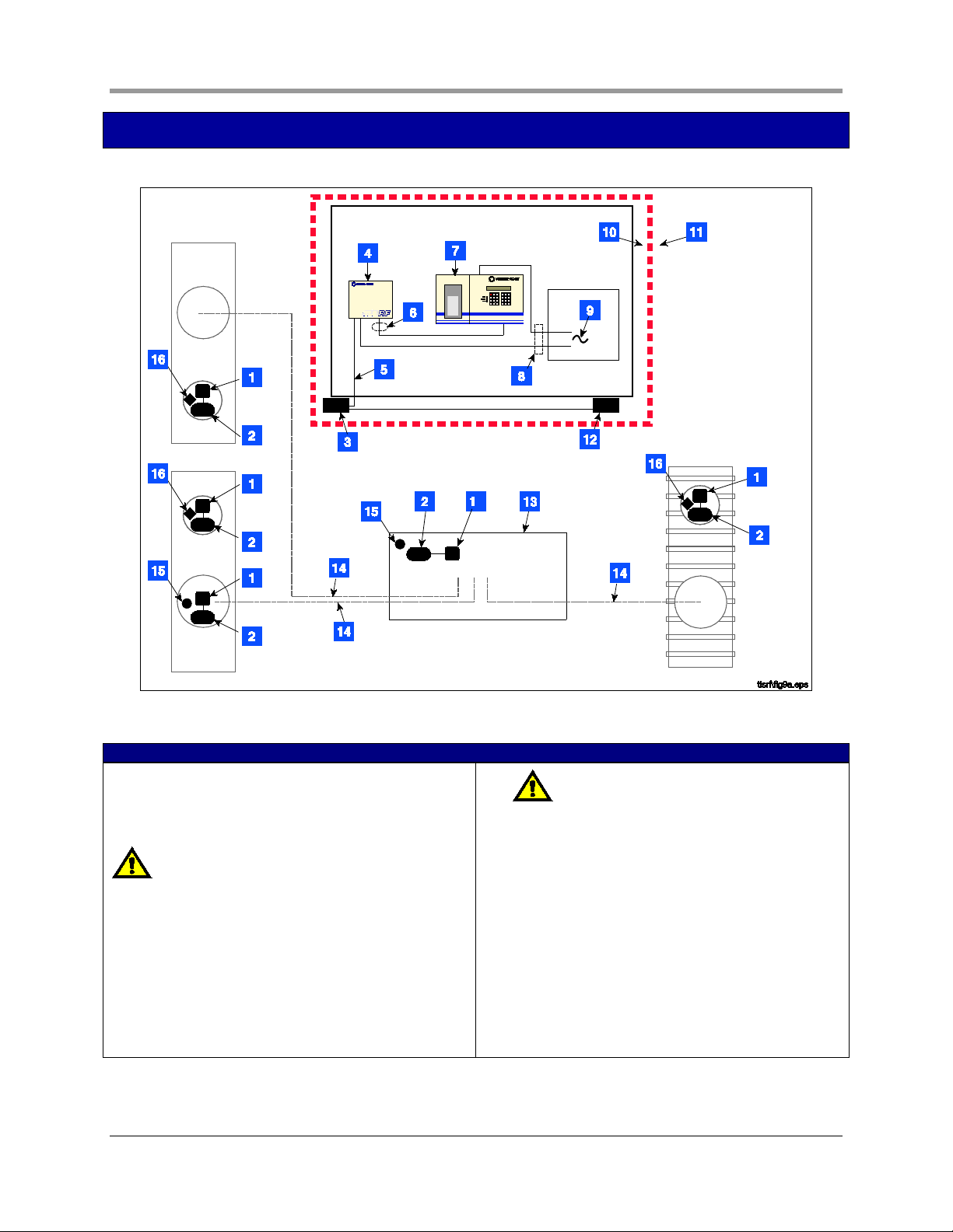
Site Considerations - Control Drawing
Figure 1. Control Drawing - Example TLS RF Wireless System Site Layout
LEGEND FOR NUMBERED BOXES IN FIGURE 1
To be installed in accordance with the National Electrical
Code, NFPA 70 and the Code for Motor Fuel Dispensing
Facilities and Repair Garages (NFPA 30A), or other local
code such as the CEC, Canadian Electrical Code.
WARNING! Substitution of components may impair
intrinsic safety.
Circuitry within the console barrier forms an intrinsically
safe, energy-limited system. This system is intrinsically safe
for use in a Class I, Group D hazardous location.
1. Battery Pack
2. Transmitter
3. Receiver
4. TLS RF (Vm = 250 V)
5. RS-485 Cable (Belden #3107A or equiv.)
6.
7. TLS console (Vm = 250 V)
8. Conduit that enters power wiring knockout.
9. 120 or 230 Vac from power panel.
10. Non-hazardous area
11. Hazardous area (Class I, Div. 1, Group D)
12. Repeater (1)
13. Dispenser sump
14. Underground product line
15. Sump sensor
16. Mag probe
NOTE: Intrinsically safe wiring shall be installed
in accordance with Article 504-20 of the NEC, ANSI/
NFPA 70. Maximum probe/sensor cable length 1000
ft. (304 m).
4
Page 10

Installation Guide National Electrical Code Compliance
National Electrical Code Compliance
The following information is for general reference and is not intended to replace recommended National
Electric Code (NEC) procedures. It is important for the installer to understand that electrical equipment and
wiring located in Class I, Division 1 and 2 installations shall comply with the latest appropriate articles found in
the National Electric Code (NFPA 70) and the Code for Motor Fuel Dispensing Facilities and Repair Garages
(NFPA 30A), or other local code such as the CEC, Canadian Electrical Code.
TLS RF UNIT-TO-TLS CONSOLE WIRING
Wire Type
To ensure the best operating systems available, Veeder-Root REQUIRES the use of shielded cable for probe
outputs regardless of conduit material or application. In these installations, shielded cable must be rated less
than 100 picofarad per foot and be manufactured with a material suitable for the environment, such as Carol™
C2534 or Belden™ 88760, 8760, or 8770.
Wire Length
Improper system operation could result in undetected potential environmental and health hazards if the TLS
RF-to-TLS Console wire runs exceed 1000 feet. Wire runs must be less than 1000 feet to meet intrinsic
safety requirements.
Splices
Veeder-Root recommends that no splices be made in the wire run between the TLS RF and the TLS Console.
Each splice degrades signal strength and could result in poor system performance.
Wire Gauges - Color coded
Shielded cable must be used in all installations. TLS RF-to-TLS console wires should be #14-#18 AWG
stranded copper wire and installed as a Class 1 circuit. As an alternate method when approved by the local
authority having jurisdiction, 22 AWG wire such as Belden 88761 may be suitable in installations with the
following provisions:
- Wire run is less than 750 feet
- Capacitance does not exceed 100 pF/foot
- Inductance does not exceed 0.2 µH/foot
TLS RF POWER WIRING
Wires carrying 120 or 240 Vac from the power panel to the TLS RF should be #14 AWG copper wire for line,
neutral and chassis ground (3); and #12 AWG copper wire for barrier ground (1).
5
Page 11
Installation Guide National Electrical Code Compliance
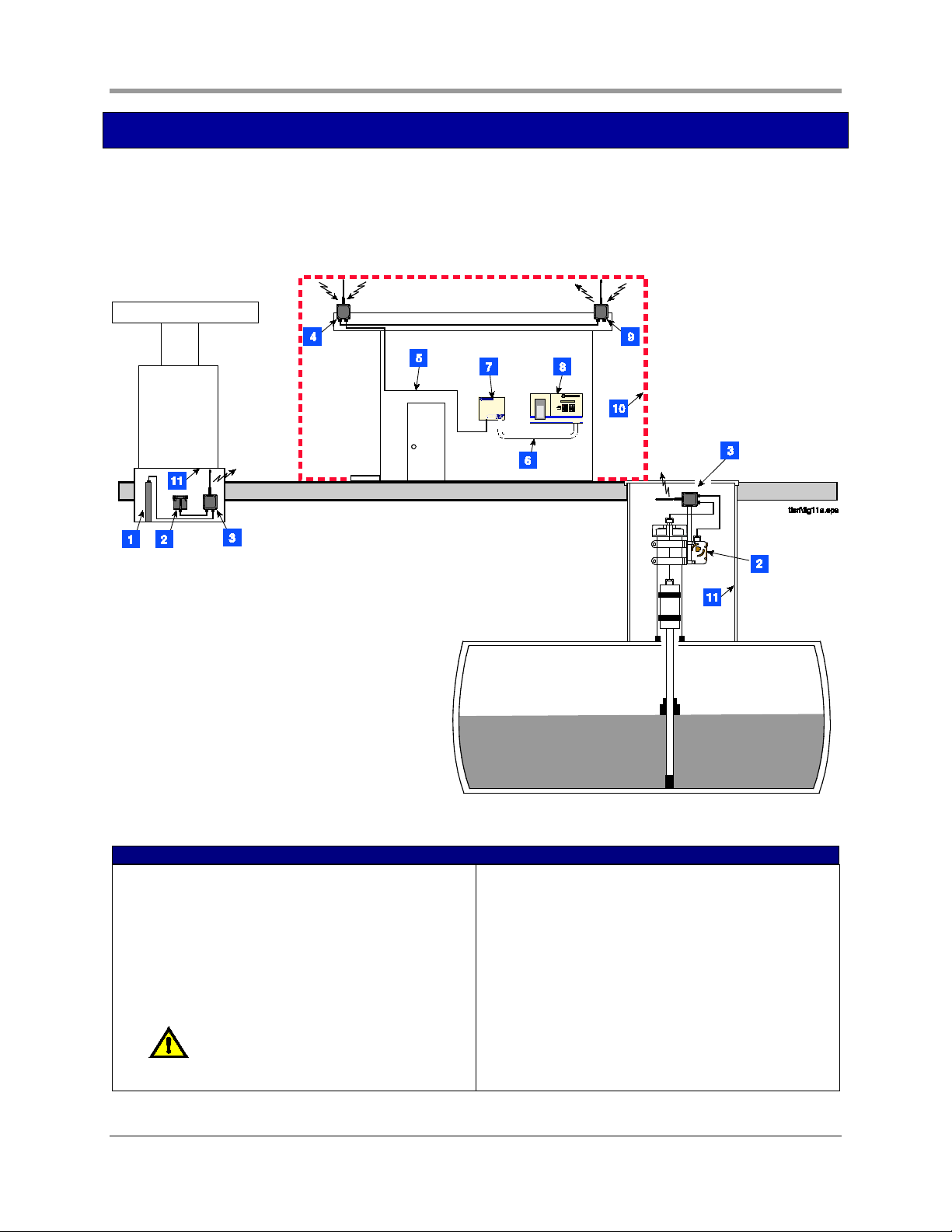
TLS RF Wireless System Overview
Figure 2 illustrates an example TLS RF Wireless System installation. In the figure only one tank is shown, but
each tank being monitored by a Mag probe would require a battery pack/transmitter pair. The repeater
component may be required if the system receiver, mounted on building’s outside wall, has difficulty receiving
signals from any of the transmitters.
Figure 2. Example TLS RF Wireless System component installation
LEGEND FOR NUMBERED BOXES IN FIGURE 2
1. Dispenser pan Mag Sump sensor
2. Battery Pack
3. Transmitter
4. Receiver
5. RS-485 cable (Belden #3107A or equiv.)
6. Probe wiring (up to 8 Mag probes/Mag Sump
sensors) - conduit connects via intrinsically safe
knockouts on both consoles.
NOTE: Intrinsically safe wiring shall be
installed in accordance with Article 504-20 of the
NEC, ANSI/NFPA 70.
7. TLS RF
8. TLS console
9. Repeater
10. Non-hazardous area
11. Hazardous area, Class I, Div. 1, Group D
6
Page 12
Installation Guide National Electrical Code Compliance
0.34''
(8,6 mm) typ.
7.4"
(188 mm)
6.4''
(163 mm)
5.7''
(145 mm)
2" (51 mm)
5.3''
(135 mm)
consoles\tlsrf\fig3.eps
0.22'' (5,6 mm) dia.
3.75"
(95mm)
0.4''
(10 mm)
0.93''
(23,6 mm)
0.93''
(24 mm)
1.25''
(32 mm)
0.93''
(23,6 mm)
2.6''
(66)
0.7''
(17,8)
0.93''
(24 mm)
6.7"
(170 mm)
1.18''
(30 mm)
1
1
2
1
2
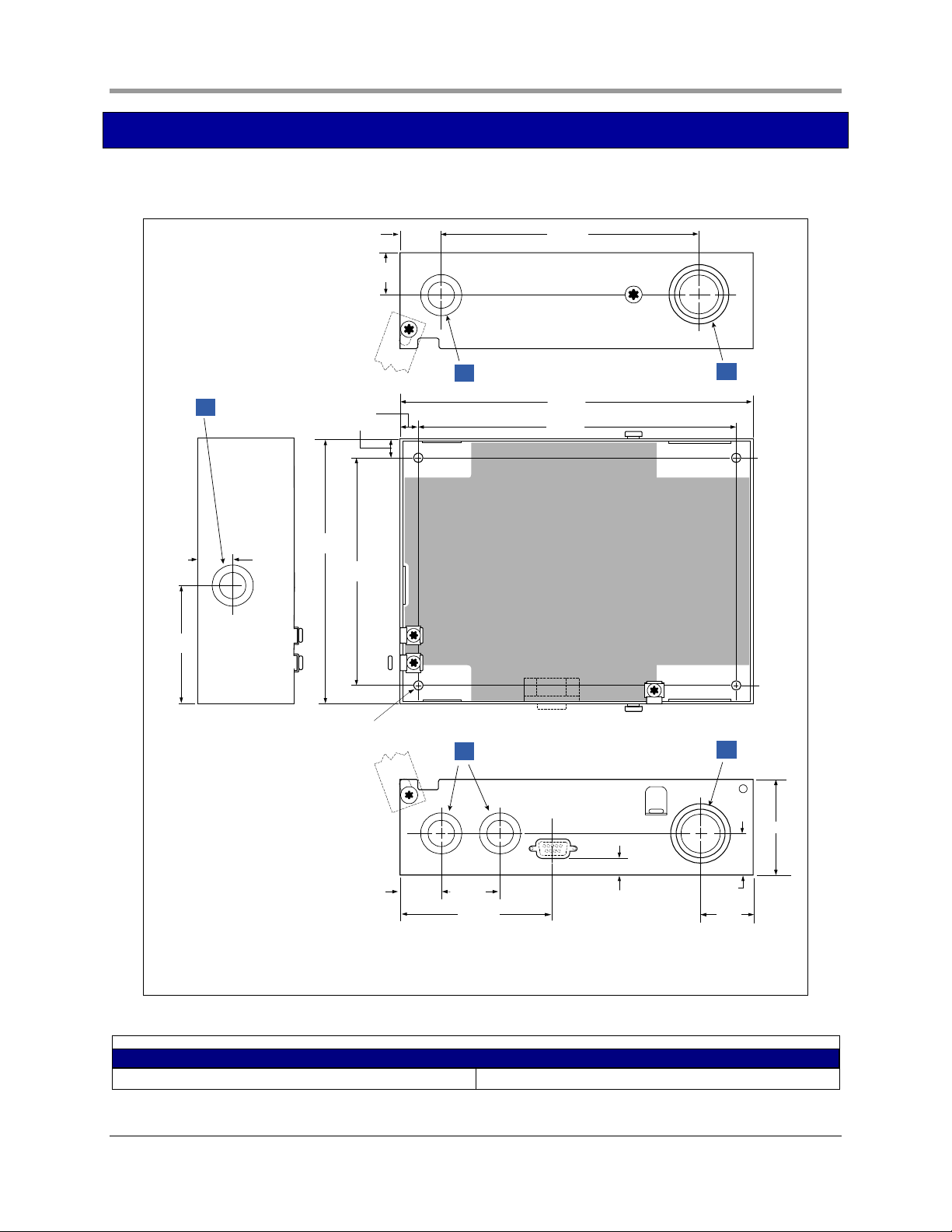
Equipment Dimensions
Dimensions of the TLS RF are shown in Figure 3.
Figure 3. TLS RF dimensions and designated conduit knockouts
LEGEND FOR NUMBERED BOXES IN FIGURE 3
1. Designated power wiring knockouts. 2. Designated intrinsically-safe wiring knockouts.
7
Page 13
Installation Guide National Electrical Code Compliance
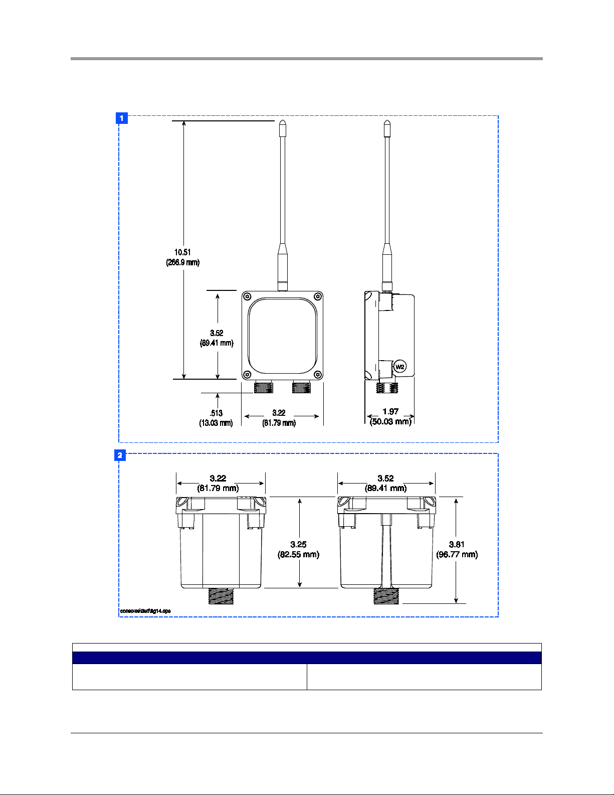
Dimensions of the receiver, transmitter, repeater, and battery housing are shown in Figure 4.
Figure 4. Wireless component dimensions
LEGEND FOR NUMBERED BOXES IN FIGURE 4
1. Receiver, transmitter, and repeater dimensions 2. Battery housing dimensions
8
Page 14
Installation Guide Wiring the TLS RF
TLS RF Installation
Selecting a Location for the TLS RF
WARNING
Explosive vapors or flammable liquids could be present near locations where fuels
are stored or being dispensed. The TLS RF is not explosion proof.
An explosion or fire resulting in serious injury or death, property loss and
equipment damage could occur if the console is installed in a volatile, combustible
or explosive atmosphere (Class I, Division 1 or 2).
Do not install this unit in a volatile, combustible, or explosive atmosphere..
The TLS RF must be mounted indoors, protected from severe vibration, extremes in temperature and humidity,
and other conditions that could harm computerized electronic equipment.
Ensure that the TLS RF is located where neither it nor its associated cabling will be damaged by doors,
furniture, etc. Consider the ease of routing wiring, and ducting to the TLS console. Check that the mounting
surface is strong enough to support the unit’s weight of about 4 pounds.
Mounting the TLS RF
Install the unit’s fastening devices to the mounting surface using the hole pattern (6.7” x 5.7”) shown in Figure
3. Mounting screws up to 3/16” diameter may be used.
Install metal conduit (1/2-inch I.P.S.) between the upper power side knockout on the unit and the power panel.
Figure 3 shows the three designated knockouts (one each on top, left side, and bottom) through which power
wiring can safely enter the unit.
Also install metal conduit (1/2-inch I.P.S.) between the lower intrinsically-safe wiring knockout on the TLS RF
and an intrinsically-safe wiring knockout on the TLS console for device data wiring.
9
Page 15
Installation Guide Wiring the TLS RF
Wiring the TLS RF
WARNING
The unit contains voltages which can be lethal.
Connecting power wires to a live circuit can cause electrical shock that may result
in serious injury or death.
Turn power off at the circuit breaker before connecting wiring to the TLS RF.
Attach conduit from the power panel to the unit’s power wiring knockouts only (1
on top and 1 on bottom, ref. Figure 3)
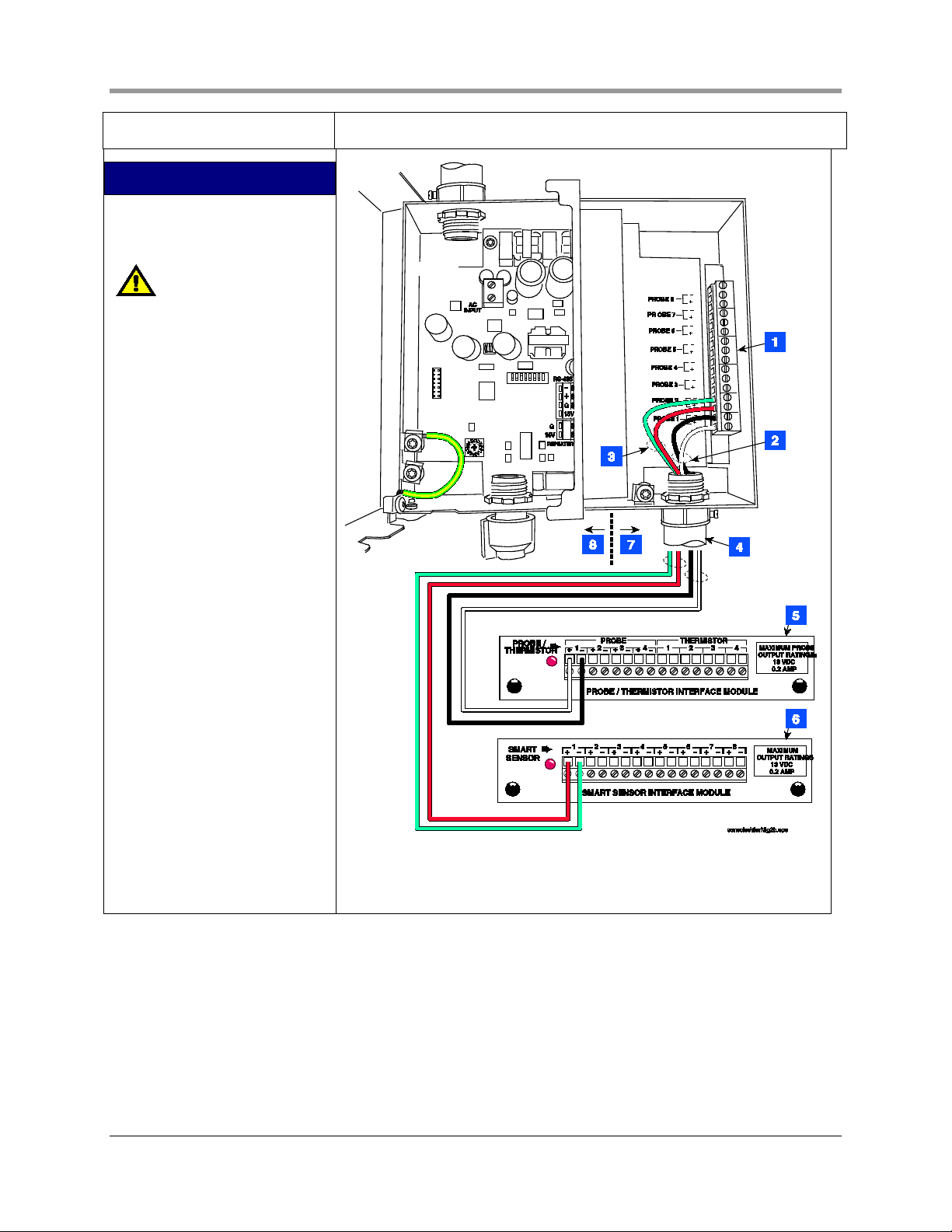
To connect power wiring see Figure 5. To connect receiver wiring see Figure 6. To daisy chain two TLS RFs,
see Figure 8 and
Figure 9. To connect TLS RF data output wiring to the TLS console see Figure 10.
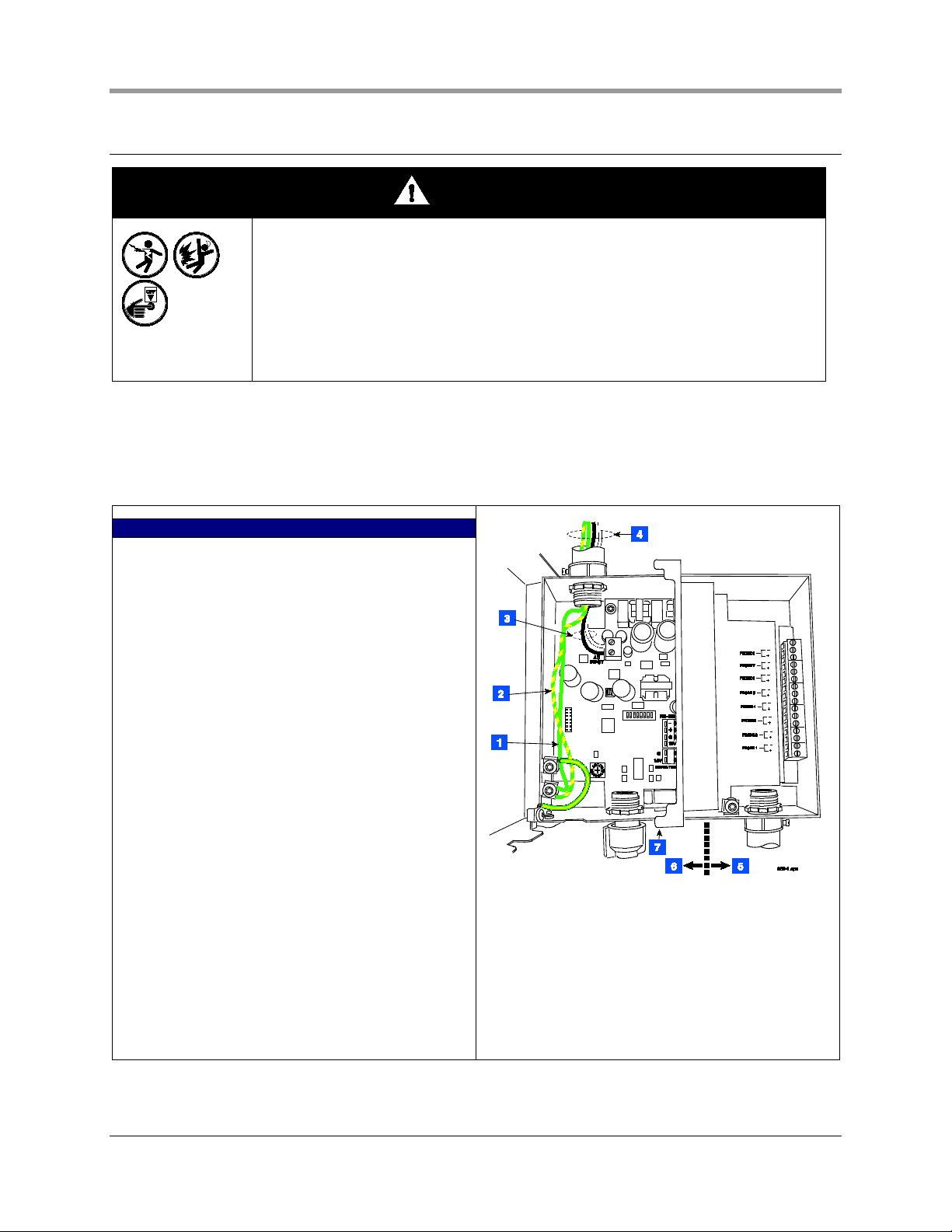
LEGEND FOR NUMBERED BOXES IN FIGURE 5
1. Attach chassis ground wire (#14 AWG) to ground lug.
2. Protective earthing conductor (green and yellow).
Attach #12AWG barrier ground wire to ground lug.
Ground must be the same as the supply and less
than 1.0 ohms to ground.
3. AC power input wires (#14 AWG) to AC INPUT
terminals.
4. POWER WIRING NOTES:
- Barrier ground must be #12 AWG or larger
diameter.
- Check to be sure that the electrical resistance between the unit ground lug and a known good earth
ground is less than 1 ohm.
- Connect the power supply wires in the power panel
to a separate dedicated circuit.
- Electrical rating power input - 120 Vac or 240 Vac,
50/60 Hz, 2 A max.
- See Figure 3 for actual locations of power conduit
knockouts into the unit. Power wiring must enter
only in one of these knockouts.
5. Intrinsically-safe side
6. Power side
7. RS-232 diagnostic port:
- Baud rate - 9600
- Data length - 8
- Parity - None
- Stop bits - 1
Figure 5. Wiring AC power to the TLS RF
10
Page 16

Installation Guide Wiring the TLS RF
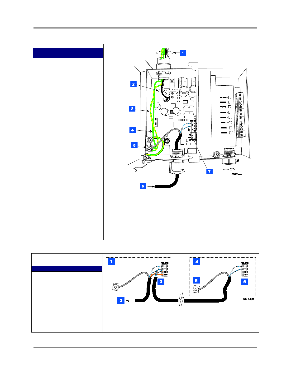
LEGEND FOR NUMBERED BOXES
IN FIGURE 6
1. Connect the shield of the RS-
485 cable to the ground lug.
2. Cord grip
3. RS-485 cable to Receiver
4. Power side
5. Intrinsically-safe side
6. NOTE: Attach one end of RS-
485 cable to RS-485 terminals
in the TLS RF and other end to
RS-485 terminals in the
Receiver. One twisted pair
connects to terminals - and +
(RS-485 signals) and the
second twisted pair connects
to terminals +15 and G
(Receiver power). You must
connect each wire of each pair
to the same terminals in the
Receiver (e.g., white w/blue
stripes to “-“ and white w/blue
stripes to “-“). (ref. Figure 24
on page 25). NOTE: see Figure
7 for wire connection tips.
NOTE: In sites with two daisychained TLS RFs, the receiver
is only connected to the
master TLS RF.
Figure 6. Wiring receiver to the TLS RF
LEGEND FOR NUMBERED BOXES IN FIGURE 7
1. Use small blade screwdriver and loosen terminal by
turning top screw over desired terminal counter
clockwise. DO NOT raise screw head above top of
hole or it may disengage from clamp.
2. Insert ¼” striped wire into terminal clamp’s side
opening and tighten screw clockwise until wire
cannot be moved in or out.
Figure 7. Connecting RS-485 Wiring
11
Page 17
Installation Guide Wiring the TLS RF
LEGEND FOR NUMBERED BOXES
IN FIGURE 8
1. POWER WIRING NOTES:
- Barrier ground must be #12
AWG or larger diameter.
- Check to be sure that the
electrical resistance - between
the unit ground lug and a
known good earth ground is
less than 1 ohm.
- Connect the power supply
wires in the power panel to a
separate dedicated circuit.
- Electrical rating power input
- 120 Vac or 240 Vac, 50/60 Hz,
2 A max.
- See Figure 3 for actual
locations of power conduit
knockouts into the unit. Power
wiring must enter only in one
of these knockouts.
2. AC power input wires (#14
AWG) to AC input terminals.
3. Protective earthing conductor
(green and yellow). Attach
#12AWG barrier ground wire
to ground lug. Ground must be
the same as the supply and
less than 1.0 ohms to ground.
4. Attach chassis ground wire
(#14 AWG) to ground lug.
5. Connect the shield of the RS-
485 cable to the ground lug.
6. RS-485 cable from master TLS
RF.
7. See Figure 9 for connections.
Figure 8. Power connections to a daisy chained TLS RF
FIGURE 9
1. TLS RF Master
2. RS-485 cable to Receiver.
3. RS-485 cable to TLS RF. Cut
the unused twisted pair back
to the cable’s jacket at each
end of the cable.
4. TLS RF Auxiliary
5. Connect the shield of the RS-
485 cable to the ground lug.
6. Connect like colored wires of
the twisted pair to like
Figure 9. RS-485 cable connections when daisy chaining two TLS RFs
12
Page 18
Installation Guide Wiring the TLS RF
terminals in both TLS RFs.
LEGEND FOR NUMBERED BOXES
Note: Output wiring from the TLS
RF to the TLS console is an
intrinsically safe circuit.
wiring shall be installed in
accordance with Article 504-20 of
the NEC, ANSI/NFPA 70.
1. Received transmitter data
2. In this example, device output
3. In this example, device output
4. 1/2” i.p.s. conduit to TLS
5. Probe interface module in TLS
6. SmartSensor interface module
7. Intrinsically-safe side
8. Power side
IN FIGURE 10
NOTE: Intrinsically safe
output terminals (1-8).
1 is a Mag probe - Observe
polarity. Note: each time a
transmission is received from
this device, LED 1 (see item 5
in Figure 11) will flash.
2 is a Mag Sump Sensor Observe polarity. Note: each
time a transmission is received
from this device, LED 2 (see
item 5 in Figure 11) will flash.
console
console.
in TLS console
Figure 10. Wiring Data Outputs from TLS RF to TLS Console
Figure 11 locates the diagnostic lights and setup switches in the TLS RF.
Each TLS RF in the site network must have a unique device set number (0 or 1). The factory default setting is
‘0’. You must select ‘0’ for the master TLS RF unit. The site’s Receiver must also be connected to the master
TLS RF.
If a second TLS RF is required, enter ‘1’ in the auxiliary TLS RF.
13
Page 19

Installation Guide Wiring the TLS RF
LEGEND FOR NUMBERED BOXES
IN FIGURE 11
1. These LEDs flash when there is
comm activity on RS-232 port
(Red = TX, Green = RX).
2. These LEDs flash when there is
comm activity on the RS-485
network (between TLS RF and
receiver).
3. Red LED is lit when TLS RF is
powered on.
4. Device timeout rotary switch
selects the maximum allowed
time to wait for communication
from transmitter before a
Probe Out/Comm alarm is
posted by TLS console (see
Appendix C for selections).
Position 1 (10 minutes) is the
factory default setting.
5. These red LEDs flash when a
message is received from a
transmitter in the monitored
device set. LED 1 is the device
wired to I.S. output terminal 1.
LED 2 is the device wired to
output terminal 2, etc.
6. Red LED flashes when TLS
console is polling for device
data.
7. S2 DIP switches 1 – 2 enter
device set address (see
Appendix C).
Figure 11. TLS RF diagnostic LEDs and switch locations
14
Page 20

Installation Guide Transmitter Installation
Wireless Component Installation
Transmitter Installation
MAG PROBE SUMP
A transmitter / battery pack pair must be installed in every tank’s probe/dispenser pan that will be monitored
by the TLS RF. Follow the steps below to install the transmitter assembly.
1. Connect the two conduit hangers from the kit (2- or 4-inch as required) to the battery pack support
bracket as shown in Figure 12.
2. Attach two conduit clamps to the battery pack support bracket as shown in Figure 13. Do not tighten
screws at this time.
LEGEND FOR NUMBERED BOXES IN
FIGURE 12
1. 2-inch or 4-inch conduit hanger [as
required] - 2 places
2. 1/4 x 20 hex head nut - 2 places
3. 1/4 x 20 x 1.25” hex head bolt - 2
places
4. Battery pack support bracket
5. 1/4 x 20 x 0.5” hex head bolt - 2
places
6. 1/4 x 20 hex head nut - 2 places.
Figure 12. Attaching hangers to battery pack support bracket
15
Page 21

Installation Guide Transmitter Installation
LEGEND FOR NUMBERED BOXES IN
FIGURE 13
1. #10 x 1/2’’ screw - 2 places
2. Clamp - 1/2” conduit - 2 places
3. #10 x 1/2’’ hex nut - 2 places.
Figure 13. Attaching conduit clamps to battery pack support bracket
3. Attach two conduit clamps to the transmitter as shown in Figure 14. Do not tighten screws at this time.
LEGEND FOR NUMBERED
BOXES IN FIGURE 14
1. #10 x 1/2’’ taptite screw -
2 places
2. Clamp - 1/2” conduit - 2
places
3. Transmitter housing
Figure 14. Attaching conduit clamps to transmitter housing
4. Loosen the probe cable cord grip and remove the riser cap. Thread the probe cable through the two
conduit hangers as you slide the hanger/bracket assembly onto the riser. Adjust the conduit hangers until
the top one is 3 - 4 inches below the top of the riser as shown in Figure 15. Tighten the two conduit
16
Page 22

Installation Guide Transmitter Installation
hanger bolts to secure the bracket on the riser. Loosen the cord grip in the top of the riser cap and push
the probe cable up through the cord grip and replace the riser cap and tighten the probe cable cord grip.
Insert a piece of ½-inch conduit or ducting into the loosened conduit clamps in the battery pack support
bracket. The conduit can be positioned below the manhole cover from 1 to 6 inches, as required for best
signal reception. Place a mark on the conduit above the top clamp. Remove the conduit to a nonhazardous location and cut off the excess length. Push the conduit down through the two clamps until the
top clamp is below the mark on the conduit and tighten the two clamps.
LEGEND FOR NUMBERED BOXES
1. 1/2” conduit or ducting
2. Clamp - 1/2” conduit - 2 places
3. Conduit hanger bolts - 2 places
4. Riser cap
5. Cord grip
6. Probe cable
IN FIGURE 15
(not visible in this view)
Figure 15. Installing transmitter support conduit
5. Loosen the clamps on the back of the transmitter and slide the two clamps down over the conduit as
shown in Figure 16. Position the transmitter until the top clamp is about 1/4” below the top of the conduit
and tighten the clamps just enough to keep the transmitter from sliding down.
17
Page 23

Installation Guide Transmitter Installation
LEGEND FOR NUMBERED BOXES IN
1. See Step 6 below.
2. Clamps - 2 places
FIGURE 16
Figure 16. Installing transmitter onto support conduit
6. Rotate the transmitter until its antenna is oriented relative to the repeater/receiver antennas as shown in
Figure 17 and tighten the two clamps on the back of the transmitter.
LEGEND FOR NUMBERED BOXES IN FIGURE 17
1. Building
2. Receiver
3. Approximate midpoint between repeater and
receiver.
4. Repeater
5. Transmitter antenna - orient antenna until it is
perpendicular to a point that is approximately
the midpoint between the repeater and the
receiver.
Figure 17. Orienting transmitter to receiver & repeater
18
Page 24

Installation Guide Mag Sump Sensor Installations - STP Sump
7. Insert the battery pack into the battery support bracket as shown in Figure 18.
8. Attach power/probe cables as described in the section below entitled “Connecting cables to the
Transmitter”.
LEGEND FOR NUMBERED
BOXES IN FIGURE 18
1. Tie wrap cables
2. Probe cable
NOTE: Intrinsically
safe wiring shall be
installed in accordance with
Article 504-20 of the NEC,
ANSI/NFPA 70.
3. Probe Riser
4. Red battery ID labels - 2
places
5. Battery pack - insert into
support bracket
Figure 18. Mag Probe Installation Example (in operational configuration)
Mag Sump Sensor Installations - STP Sump
A transmitter/battery pack pair can be installed with a Veeder-Root Mag Sump sensor within the STP sump.
The transmitter /battery pack installs similar to the way it installs in probe sumps. The exception is that the
support brackets will attach to the pump’s 2-inch discharge piping rather than to the STP’s 4-inch riser as
shown in Figure 18.
Install the Mag Sump sensor using the included universal sensor mounting kit and following the instructions
included with the sensor.
Once the sensor/battery pack is installed, attach power/sensor cables as described in the section below
entitled “Connecting cables to the Transmitter”.
19
Page 25

Installation Guide Mag Sump Sensor Installations - Dispenser Pan Sump
Mag Sump Sensor Installations - Dispenser Pan Sump
1. A transmitter /battery pack pair can be installed with a Veeder-Root Mag Sump sensor within the
dispenser sump.
2. Install the Mag Sump sensor in the dispenser’s pan area following instructions accompanying the sensor.
3. Using two taptite screws from the kit, attach the transmitter housing to the side of the battery support
bracket that has the two circular slots (see Figure 19). Do not tighten screws at this time.
4. Get the 1 inch by 6 inch slotted flat bar from the kit and two ¼ x 3-inch bolts and two nuts. Clamp the
bracket to a section of the square support tubing in the sump, below the shear valve (see Figure 20).
5. Rotate the transmitter antenna as close as possible to a horizontal position then tighten two mounting
screws in housing.
6. Insert the battery pack into its support bracket - do not connect battery cable to battery pack at this time.
7. Attach power/sensor cables as described in the section below entitled Connecting cables to the
Transmitter.
LEGEND FOR NUMBERED BOXES IN FIGURE 19
1. Transmitter
2. #10 x 1/2” taptite screws (2)
3. Battery support bracket
Figure 19. Attaching transmitter to battery support bracket
20
Page 26

Installation Guide Mag Sump Sensor Installations - Dispenser Pan Sump
Figure 20. Example transmitter installation in dispenser sump (in operational configuration)
LEGEND FOR NUMBERED BOXES IN FIGURE 20
1. Shear valve
2. Transmitter
3. Battery pack
4. Using 1 x 6 slotted flat bar and two ¼ x 3 bolts from kit, clamp battery support bracket to square tubing support.
5. Battery caution label attached to battery cable (2 places)
6. Dispenser mag sump sensor
7. Sensor cable
NOTE: Intrinsically safe wiring shall be installed in accordance with Article 504-20 of the NEC,
ANSI/NFPA 70.
8. Dispenser sump
21
Page 27

Installation Guide Mag Sump Sensor Installations - Dispenser Pan Sump
CONNECTING CABLES TO THE TRANSMITTER
1. Remove the cover of the transmitter and set it aside Make sure the battery/dc power cable is not
connected to the battery pack or dc power source at this time.
2. Push the probe/sensor cable through the left cord grip bushing and the battery cable through the right
cord grip (see Figure 21). Strip the cable leads as shown in Figure 22.
WARNING! To prevent ignition of flammable or combustible atmosphere disconnect power
before servicing.
3. Set S1 and S2 DIP switches as desired (ref. Appendix C).
4. Connect the Mag probe/Mag Sump sensor cable to the PROBE terminal block (white to PWR and black
to GND) and the battery pack/dc power cable to the BATTERY terminal block (white to +IN and black to IN) as shown in Figure 21.
5.
TRANSMITTER WIRING
1. Green LED – Unit status.
2. Red LED – Radio status.
3. S2 DIP switch
4. Red LED – Flashes only when radio is
5. Battery power in terminals (+IN and –
6. Cable from battery pack – observe
7. Cable from probe or sensor
8. Probe/sensor input terminals (PWR
9. S1 DIP switch
Hand tighten both cable entry cord grip nuts to prevent water entry!
LEGEND FOR NUMBERED BOXES IN
FIGURE 21
powered on in Diagnostic Mode.
IN). Observe polarity!
polarity!
and GND) - observe polarity!
22
Figure 21. Wiring the Transmitter
Page 28

Installation Guide Receiver Installation
Figure 22. Connecting wiring to transmitter terminal blocks.
LEGEND FOR NUMBERED BOXES IN FIGURE 22
1. Strip back cable and wire jackets the amount shown.
2. Use a screwdriver with the proper blade width
3. Insert the probe cable ends through the housing and into the proper lower openings in the terminal block as you
tighten down the retaining screws.
Both wires must be tight in terminals!
6. To assure a water-tight seal between the cover and the enclosure, follow these steps:
a. Insert the four cover screws through the cover and then press on the retaining washers to hold the
screws in place.
b. Make sure that the cover gasket is free of dirt and debris on both sides of the gasket and that the inside
of the cover is clean in the gasket area.
c. Position the gasket into the cover groove, assuring that it is pressed fully into the groove and sitting
completely flat.
d. Assemble the cover onto the enclosure, tightening the screws in a couple of turns each. Using an
alternating ‘X’ pattern, continue to tighten the screws until they are all tight.
7. Attach the red battery ID labels from the installation kit to the battery cable at both ends as shown in
Figure 18.
8. Refer to the Site Startup Procedure before attaching battery cable to battery pack connector.
Receiver Installation
1. One receiver is required per site and it is mounted in the vertical position (antenna up) on the outer wall of
the same building housing the TLS RF. The receiver is attached to its mounting bracket with #10 x 1/2”
taptite screws from its install kit (see Figure 23). The L-bracket is then mounted on the outer wall of the
building using appropriate fasteners (customer supplied). NOTE: Locate the receiver on the side of the
building facing the tanks to provide an unobstructed signal path. When locating the mounting position,
keep in mind that the RS-485 cable connecting the receiver to the TLS RF must be less than 250 feet in
length. Avoid placing the receiver near motors (e.g., power roof vents), fluorescent lighting (min. 1 foot
separation), pumps, welders.
2. Run the RS-485 cable (Belden #3107A or equiv.) from the TLS RF through the building’s wall to the
receiver. Caulk the cable where it passes through wall openings. Use cable clamps at appropriate
intervals to secure the cable to the walls.
23
Page 29

Installation Guide Receiver Installation
3. Note that the receiver cover label indicates the cord grip to be used for the RS-485 cable from the TLS
RF. Loosen that cord grip then remove the cover of the receiver and set it aside.
4. Note that the Receiver cover label indicates the cord grip to be used for the RS-485 cable from the TLS
RF and the cable to the Repeater (if used). If you are installing a Repeater in this site, loosen both cord
grip nuts, otherwise loosen the TLS RF cord grip, then remove the cover of the Receiver and set it aside.
5. Push the TLS RF RS-485 cable through the loosened cord grip. Strip back the jacket from the end of the
cable as shown in Figure 22. Note that there are two twisted pair color-coded wires in the cable (e.g., a
white with blue stripe and blue with white stripe pair and a white with orange strip and orange with white
stripe pair).
6. One of the pairs is for RS-485 communication (- & + terminals) and the other pair is for receiver power
(+15 Vdc & Gnd). Using Figure 24 as a guide, connect the wires of the two twisted pairs to the RS-485
terminals.
Record which wire attaches to each terminal to help you attach the other end of that wire to the identically
marked terminal in the TLS RF.
7. Referring to your connection notes in step 5 above, connect the other end of the RS-485 cable to the RS-
485 terminal block in the TLS RF (ref. Figure 6 on page 11).
8. If a Repeater is used and powered by the Receiver, push the two wire power cable (to Repeater) through
the +15 Vdc cord grip of the Receiver. Strip back the jacket from the end of the cable as shown in Figure
22. Attach the dc power cable (white to +15 and black to GND) to the Repeater terminal block (item 9 in
Figure 24).
LEGEND FOR NUMBERED BOXES IN FIGURE
1. Receiver or repeater
2. 0.280” diameter hole (2) – mount this
narrow side of bracket to wall or post
3. Mounting bracket
4. #10 x 1/2” taptite screws
Receiver is only suitable for use in and
over a non-hazardous location.
23
Figure 23. Attaching mounting bracket to receiver or repeater
9. Set S1 and S2 DIP settings as desired (ref. Appendix C).
10.
Hand tighten both cord grip nuts to prevent water entry!
11. To assure a water-tight seal between the cover and the enclosure, follow these steps:
a. Insert the four cover screws through the cover and then press on the retaining washers to hold the
screws in place.
b. Make sure that the cover gasket is free of dirt and debris on both sides of the gasket and that the inside
of the cover is clean in the gasket area.
c. Position the gasket into the cover groove, assuring that it is pressed fully into the groove and sitting
completely flat.
24
Page 30

Installation Guide Repeater Installation
d. Assemble the cover onto the enclosure, tightening the screws in a couple of turns each. Using an
alternating ‘X’ pattern, continue to tighten the screws until they are all tight.
LEGEND FOR NUMBERED BOXES IN FIGURE 24
RECEIVER
1. RS-485 Comm Activity
XMIT (Red) LED – flashes when message
transmitted to TLS-RF
RCV (Green) LED – flashes when message
received from TLS- RF
PWR (Red) LED – receiver power-on indicator
2. Green LED – Unit status
3. Red LED – Radio status
4. Connect the like color pairs of the RS-
485/power cable to the same RS-485
terminals in both the receiver and the master
TLS RF (ref. Figure 6 on page 11).
5. S1 DIP switch
6. RS-485 cable
7. A solid bushing must be installed to seal the
receiver when this cord grip is unused. In sites
where a repeater is powered from the receiver,
the repeater’s power cable enters through this
cord grip and attaches to item 9.
Hand tighten both cord grip nuts to
prevent water entry!
8. S2 DIP switch
9. +15 Vdc power source for the repeater.
Figure 24. Wiring the receiver
Repeater Installation
1. One repeater is installed per site which relays transmitter signals to the site’s receiver. The repeater is
mounted in a vertical position on same side of the building as the receiver (preferably), and in a direct line
of sight with the receiver (ref. Figure 17 on page 18).
2. The repeater is attached to its mounting bracket with #10 x 1/2” taptite screws from its install kit (ref.
Figure 23 on page 24). The L-bracket is then mounted on the outer wall of the building using appropriate
fasteners (customer supplied).
3. Note the cover of the repeater indicated the cord grip to be used for the cable connecting the repeater to
its dc power source. Loosen the +15 Vdc labeled cord grip, then remove the cover of the repeater and
set it aside. Push the 2-wire power cable through the power cable cord grip and into the Repeater.
4. Set S1 and S2 as desired (refer to Appendix C).
5. Connect the 2-wire dc power cable to the repeater terminal block white to +15 and black to GND (see
item 7 in Figure 25).
25
Page 31

Installation Guide Repeater Installation
6. To assure a water-tight seal between the cover and the enclosure, follow these steps:
a. Insert the four cover screws through the cover and then press on the retaining washers to hold the
screws in place.
b. Make sure that the cover gasket is free of dirt and debris on both sides of the gasket and that the inside
of the cover is clean in the gasket area.
c. Position the gasket into the cover groove, assuring that it is pressed fully into the groove and sitting
completely flat.
d. Assemble the cover onto the enclosure, tightening the screws in a couple of turns each. Using an
alternating ‘X’ pattern, continue to tighten the screws until they are all tight.
7.
Hand tighten both cable entry cord grip nuts to prevent water entry!
8. The other end of the repeater’s dc power cable connects to the receiver’s +15 Vdc output terminal (ref.
item 9 in Figure 24), or to a non-interruptible, Class 2, 15 Vdc power source.
LEGEND FOR NUMBERED BOXES IN FIGURE 25
REPEATER
1. Red LED – on when power is applied.
2. Green LED – Unit status
3. Red LED – Radio status
4. S1 DIP switch
5. DC Power input cable
6. S2 DIP switch
7. DC power input terminals ( +15 Vdc and ground
)
Pay close attention to the polarity of the +15 V.
Reversing the connections can cause damage to the
TLS RF!
Repeater is only suitable for use in and over a
non-hazardous location.
26
Figure 25. Wiring the repeater
Page 32

Installation Guide Identifying Devices in the TLS RF Site Network
Network Setup
Hardware Overview
An example TLS RF site network illustrating a 16 transmitter configuration is shown in Figure 26. The
maximum number of transmitters permissible in a TLS RF Wireless site is 16 (requires 2 TLS RF units).
LEGEND FOR NUMBERED BOXES IN
FIGURE 26
1. Site Network
2. Wireless network
3. VR bus
4. Up to 16 transmitters are
supported in this example site.
5. Repeater
6. Receiver
7. TLS RF, one required per 8
transmitters
8. TLS-350R console
Figure 26. Example Site Network diagram
NOTE: The device type (i.e., mag probe or mag sump sensor) and quantity permissible in your site’s
network is dependent on the capabilities of the installed TLS console.
Identifying Devices in the TLS RF Site Network
The Site ID must be identical for all transmitters, the repeater, and the receiver in the site’s wireless network.
Each transmitter in the site’s wireless network must have a unique device ID number (from 1 – 16)
Each repeater in the site’s wireless network must have a unique repeater ID number (from 0 – 15)
The receiver on the site’s VR bus must have a unique VR bus address (from 0 – 3).
Each TLS RF in the site’s network must have a unique Device Set address (Master at 0 and Auxiliary at1).
All ID numbers are converted into binary form and entered using DIP switches located in each device.
You must enter the IDs in each device before it is installed.
Create a site network worksheet in which you list each transmitter, its location and its Site ID. Using this
worksheet when setting device DIP switches and connecting signal wires will help ensure the TLS console is
receiving the intended data transmissions.
27
Page 33

Installation Guide Identifying Devices in the TLS RF Site Network
Site Startup Procedure
After installing and wiring all equipment, follow the startup steps below.
1. Open the cover of the TLS RF, then power it up. The green/red LEDs indicating RS-485 network activity
between the receiver and TLS RF should be flashing rapidly (ref. item 2 in Figure 11 on page 14). If Yes,
continue to the next step. If No, check the red LED. If it is not flashing, replace the TLS RF. If the green
LED is not flashing, the receiver is not responding. Go the receiver and remove its cover. Check the RS485 wiring connections to verify that each wire of the twisted pairs is connected to the same terminal in
the receiver that its other end is connected to in the TLS RF. If the wiring connections are correct, the
PWR LED (item 1 in Figure 24) and green LED (item 2 in Figure 24) should be lit. If the PWR LED is lit,
but the green LED is not lit, the receiver is inoperative and needs replacing. If the PWR LED is not lit,
measure the voltage across the twisted pair power wires, it should be +15 Vdc. To isolate a faulty cable,
measure the voltage across the +15 and GND terminals of the RS-485 terminal strip in the TLS RF (ref.
Figure 6 on page11). Replace the cable, TLS RF, or receiver as necessary.
2. Referencing your site network worksheet, go to the first transmitter and connect its power cable to the
battery pack. This will put the transmitter into the continuous mode, ‘forcing’ it to transmit every 6 seconds
for 30 minutes (default).
3. At the TLS RF, you should see one of the 8 red transmission received LEDs flashing every 6 seconds,
indicating receipt of each transmission from the transmitter (item 5 in Figure 11 on page 14). If yes, record
on your site network worksheet which number LED is flashing for this transmitter and then go to step 3a. If
one of the LEDs is not flashing, go to step 3b.
a. Go back to the transmitter and replace the sump lid, or if a dispenser, close the sump’s access
cover. Return to the TLS RF and verify that the same LED continues to flash every 6 seconds. If
yes, the receiver is continuing to communicate with the transmitter after the manhole cover or
other obstruction was replaced. Go back to the same transmitter, remove the manhole cover and
disconnect the power cable from the battery pack and continue to step 4. If the LED is not
flashing every 6 seconds, the receiver is not picking up the transmitter’s signal. Return to the
transmitter and remove the obstruction. Referring to your site network worksheet, verify that the
correct Site ID is entered. Verify that the transmitter’s antenna is oriented to the receiver as
shown in Figure 17 on page 18, if it is move it around and recheck at the TLS RF to see if the
new position helps. Replace the obstruction and recheck the LED in the TLS RF. If it is not
flashing, try moving the transmitter down in the sump, then replace the obstruction and recheck
the LED in the TLS RF. If reorienting the antenna or moving the transmitter doesn’t help, make a
note on your worksheet that the signal from this transmitter is not being received, disconnect the
transmitter power cable at the battery pack, and continue to Step 4.
b. Remove the cover of the problem transmitter. The green LED (item 1 in Figure 21 on page 22)
should flash indicating that the probe is being read. The red LED should also flash indicating the
transmitter linked with the receiver and transmitted the probe’s data. This green/red flash
sequence should occur every 6 seconds while the transmitter is in continuous mode. If there is no
green flash, check the probe cable’s wiring connections. If the green LED flashes every 6
seconds, but the red LED doesn’t flash, then the transmitter is reading the probe data, but for
some reason is not linking with, and transmitting to the receiver. However, you will have to wait
until you check additional transmitters before determining that the receiver is not functioning
correctly. If the green LED is blinking quickly (about a tenth of a second) every 6 seconds, it can
mean one of several probe errors depending on the number of blinks. Before continuing to step
4, disconnect the transmitter power cable at the battery pack.
28
Page 34

Installation Guide Identifying Devices in the TLS RF Site Network
4. Repeat Steps 2 and 3 for each of the remaining transmitters. As you power up each of the remaining
transmitters and check their reception at the TLS RF, make notes on your site network worksheet as to
whether the transmitter signals are being received successfully, which one of the 8 red transmission
received LEDs in the TLS RF is flashing every 6 seconds, probe problems, etc., for later troubleshooting.
5. If each transmitter is being received at the TLS RF(s), go around to each transmitter, reconnect the
transmitter’s power cable to the battery, and replace the sump or dispenser cover as appropriate. Go to
the TLS console and configure all site probes and mag sump sensors. Check for any probe out/comm
alarms. If none are observed, the startup is complete.
If some transmitters are not being received at the TLS RF, you will have to install additional repeaters as
necessary. The repeater requires a Class 2, 15 Vdc power source.
29
Page 35

Installation Guide Antenna Propagation Basics
Troubleshooting
Antenna Propagation Basics
The Veeder-Root TLS RF Wireless site consists of one Master (Receiver) and one or more Slave units
(Transmitters/Repeaters) and uses the Frequency Hopping Spread Spectrum (FHSS) method of signal
transmission in which each transceiver is programmed to follow a set of channels called the ‘Hopset’. Federal
Communication Commission (FCC) regulations state that for FHSS: each transceiver may dwell on any given
frequency in the Hopset for no more than 400 milliseconds in any 30 second period. Authorized channel
bandwidth is 1 MHz and channel spacing is 25 kHz.
The propagation of radio waves in FHSS applications, i.e., the TLS RF Wireless System, is influenced by
several factors:
ANTENNA OPERATION
The antenna is a transducer, which converts radio frequency electrical energy fed to it (via the transmission
line) to an electromagnetic wave propagated into space. Assuming that the operating frequency in both cases
is the same, as in the TLS RF Wireless System, this process is reciprocal in nature - the antenna will perform
identically in Transmit or Receive mode. The same Antenna and Transmission Line path is used for both
transmit and receive functions.
FREE SPACE LOSS
Signal power is diminished by geometric spreading of the wavefront, commonly known as Free Space Loss
(FSL). For TLS Wireless sites having relatively small distances between the Receiver and Transmitters, FSL is
not an issue.
ATTENUATION
When the RF signal passes though solid objects, some of the signal power is absorbed. The most convenient
way to express this is by adding an “allowed loss” to the Free Space loss. Attenuation can vary greatly
depending upon the structure of the object the signal is passing through. Metal in the barrier greatly increases
the attenuation. Thickness also increases the loss. General rules of thumb for attenuation are:
• Trees account for 10 to 20 dB of loss per tree in the direct path. Loss depends upon the size and type of
tree. Large trees with dense foliage create greater loss.
• Walls account for 10 to 15 dB depending upon the construction. Interior walls are on the low end and
exterior walls, especially those with stucco, create more loss.
• Floors of buildings account for 12 to 27 dB of loss. Floors with concrete and steel are at the high end and
wood floors are at the low end.
• Mirrored walls have very high loss because the reflective coating is conductive.
SCATTERING
RF signals can reflect off of many things and the direct signal combines with signals that have reflected off of
objects that are not in the direct path. This effect is usually described as multipath, fading, Rayleigh fading or
signal dispersion. When RF signals combine they can be distorted. The distortion degrades the ability the
receiver to recover the signal in a manner much like signal loss.
30
Page 36

Installation Guide Probe Troubleshooting
RADIO LINE OF SIGHT
Radio Line of Sight (LOS) refers to the ability of the receiver to ‘see’ the transmitter. In TLS RF Wireless sites,
the preferred positioning of the Receiver is one that is visible from the Transmitter’s location. When Radio line
of sight is impossible, e.g., tanks are on opposite sides of the building, a Repeater should be installed that is
positioned at a point that is both visible from the Transmitter and from the Receiver.
ANTENNA POLARIZATION
Polarized omni-directional antennas (used in the TLS Wireless System) are subject to severe pattern distortion
in the direction of their mounting (vertically or horizontally). For this reason, the TLS RF Wireless System
Receiver’s antenna must be mounted vertically and the Transmitter’s antenna mounted horizontally (90
degrees apart).
INTERFERENCE
Interference may be caused by several possible sources:
• In-band signals originating from other systems
• Reflections, multipath
• Receiver front-end overload, produced by adjacent transmitters such as a microwave tower, etc.
The nature of Frequency Hopping Spread Spectrum systems is such that interference would tend to degrade
throughput, rather than cause the cessation of link operation. Even in such instances, the inherent immunity to
interference provides that extra margin of safety. When all antenna orientation possibilities are tried and one or
more transmitters still cannot be received, additional repeater(s) will have to be installed.
31
Page 37

Installation Guide Probe Troubleshooting
Probe Troubleshooting
1. Attach your laptop to the TLS RF’s RS-232 serial port (see Figure 27).
LEGEND FOR NUMBERED BOXES IN
1. RS-232 (DB9 female)
2. Standard RS-232 cable (customer
supplied)
3. USB to DB9 serial cable (customer
supplied)
4. PCMCIA to serial cable (customer
supplied)
5. PCMCIA card (customer supplied)
6. Laptop with a serial communications
program, such as HyperTerminal
(customer supplied).
FIGURE 27
Figure 27. Laptop to TLS RF Wireless Interface Unit example connections
Open a serial communications program, such as HyperTerminal (available in Windows under
Start\Programs\Accessories\Communications). Set the comm port settings to: 9600 Baud, 8 data bits, no
parity, 1 stop bit.
2. Perform the following steps on a PC with the HyperTerminal application program running. TLS
commands are case sensitive and use a Control-A to identify the start of a command. Enter a Control-A
by holding the Ctrl key down while pressing the A key, then release the Ctrl key. Next, type in the
command, I31500 and click on the SEND button. An example of the 315 command response in a site
with 8 transmitters is shown below.
NOTE: MAG SN = Mag Sump Sensor
DEV column
The TLS RF supports 8 devices (Mag probes or Mag Sump sensors), numbered 01 thru 08. The device
number corresponds to its I.S. data-out terminal wiring position on the TLS RF unit.
32
Page 38

Installation Guide Probe Troubleshooting
TXID Column
A site's wireless system can support up to 16 transmitters and each must have an unique ID. This column
shows the ID that was set in the transmitter when it was installed.
STATE Column
The device state is OK or OUT. When the state is OUT, the TLS RF unit will not respond to the TLS
console polling for this device. The OUT state will cause the TLS console to post a Probe-Out or Comm
alarm for this device.
REASON Column
There are four reasons for a device to have an OUT state:
NO_CNST
In order to conserve energy the transmitter sends messages in 3 groups: constant data, fuel/water data,
and fuel/water/temperature data.
For a given sensor, constant data never changes so it only needs to be transmitted once. It is however
transmitted for two-minutes following transmitter power-up, or the triggering of its service switch
(magnetically activated reed switch) and then settles down to once every 4-hours. The TLS RF unit will
store the constants in non-volatile memory so that the constant data can be restored after a power cycle.
The status of a device will be OUT if the constant data has not been received (NO_CNST).
NO_DATA
Fuel/Water data is transmitted at different rates depending on activity and power-up/service switch status.
The maximum transmission period is 2-minutes, the minimum 5-seconds.
Temperature does not have to be read as often as fuel/water data. It is transmitted once every 2 minutes
along with the fuel/water data. The status of a device will be OUT if it has not received
fuel/water/temperature data (NO_DATA).
TIMEOUT
If no transmissions are received for the timeout duration programmed in the TLS RF unit, the device OUT
status’s reason will be set to TIMEOUT. This state overrides all other states.
NO_READ
The transmitter can detect when a device is not responding correctly. In this case the transmitter will
transmit a device-out message. In turn the TLS RF will set the status of a device to OUT (NO_READ).
On power-up the TLS RF unit will read its non-volatile memory to restore constant data. If the constant
data is available it will then set the device to the OUT condition with the reason code: NO_DATA. When
fuel/water level and temperature data are received the NO_DATA condition will be removed and the
device will be set to the OK status. If there is no constant data the device OUT reason code will be
NO_CNST. The device will be removed from this state when constant and fuel/water/temperature data
are received. If no transmissions are being received from the device the TIMEOUT reason code will
replace the previous reason code.
TYPE and SN Columns
If the device constants are available, the device type and device serial number will be placed in these
columns. If the constants are not available the type column will be filled in with ‘?????’ and the serial
column with all zeros (000000).
33
Page 39

Installation Guide Resetting Data in the TLS RF Unit
TOTL COMMS
A running total of all messages received from this device. This includes messages that were repeated by a
repeater(s).
REPT COMMS Column
This column displays a running total of all messages received from this device that were repeated from a
repeater. Subtracting the repeated total from the total comms value will result in the total number of direct
messages received: Total Direct Messages = TOTL COMMS - REPT COMMS.
LAST COMM Column
This column displays the duration since the last message received from this device. Display is in
days:hours:minutes:seconds format. The 9999:99:99:99 time indicates no messages have been received
since the TLS RF unit has been powered on.
Resetting Data in the TLS RF Unit
NOTE: The data is reset when the TLS RF unit is power cycled or reset with the serial command S001
(except Constants which are in stored in flash memory).
It is also possible to reset the Total and Repeater Comms totals remotely with the following command:
S315ss149.
34
Page 40

Appendix A: Site Survey for Wireless Probes
OBJECTIVE
The objective of the site survey are:-
• To acquire information that will ensure that all the items necessary to complete the installation are ordered and
supplied.
• To establish where the system assemblies will be best located, so that this information can be passed on to the
installation team.
• To establish any site conditions or anomalies that will affect the installation
• Ultimately to ensure the completed installation is of the required high standard
METHOD
A trained person certified by GVR should undertake the site survey: this person will collect the necessary
information and then submit this information in a specified format.
Instructions to Survey Engineer
OBJECTIVE
The Survey engineer needs to provide accurate site information so that when the System is installed and
commissioned it will function reliably, and meet the requirements of the customer.
METHOD
The need for a survey will be triggered by a sales enquiry: The surveyor will require the following basic information:-
• Site name and address.
•Customer
• Telephone number
• Gauge type
• Number of tanks to be gauged
• Additional sensors
• Special instructions
Completion of Site Survey Form
OBJECTIVE
The aim of the survey sheets (or PC software) is to record data collected at the time of the survey to enable
correct equipment specification, identify all works necessary before the installation date, special tools or
equipment required for installation, and site specific data required for a successful commissioning.
A-1
Page 41

Appendix A: Site Survey for Wireless Probes Key Information
METHOD
Take all details and measurements necessary to complete the site survey.
The form has to be completed in the same format by all surveyors. This is so that when or orders are placed with
the local distributor the administrator will understand clearly the information on the survey, and will be able to
compile an accurate parts list.
Note: The local installer will be responsible for the labor element and any locally supplied parts, the survey should
provide enough information for them to be able to do this successfully.
Key Information
SURVEYORS DETAILS
• Name of surveyor
•Company
• Date of survey
• Name/address/telephone number of installation company
GENERAL SITE DETAILS
• Site name and address (include country and local postcode)
• Telephone number (s)
• Site contact name
• Oil company (or group company name)
TAN K I N F O R M AT I ON
• Number of tanks to be monitored
• No of any tanks not to be monitored
• State available probe entry size for each tank
• Check that there are no internal obstructions to the probe
• Determine the tank diameter (height) and probe length required
• Identify any tank lid that has no entry and advise action required
• Note product type of each tank
• Note SWC’s for each tank
• Note max tank capacity of each tank if available (e.g. dipstick top mark or dipchart)
• State whether the tank is single tank, and indicate the end shape if known
• State if the tank is siphon or line manifolded
• Indicate the number of lids on the tank
• Indicate if the tank has a STP fitted
• State whether the tank is single or double wall
• State the material the tank is made of
A-2
Page 42

Appendix A: Site Survey for Wireless Probes Key Information
• If double walled, does it have a leak monitoring device fitted, or are we to provide same
• State whether the tank is direct fill or offset fill
• State the approximate age of the tank
MANHOLE CHAMBER INFORMATION
• Manhole construction
- Shape (circular, square etc.)
- Wall material (concrete, etc.)
- Wall profile (smooth, ribbed)
• Manhole depth (Underside of cover to top surface of lid)
• Indicate if the manhole is less than 18 inches in depth
•Lid material
• Ease of removal (Two-man, special lifter required etc.)
• Accessibility (any restrictions?)
• Vehicle parking (are vehicles regularly parked for long periods)
PROBE RISER SPECIFICATION
• Fittings required to adapt a 2” riser to the riser entry orifice
• Max allowable riser length (formula = manhole depth – [transmitter unit height – 3 inches])
PROBE TRANSMITTER CONSIDERATIONS
• The transmitter needs to be installed towards the centre of the manhole chamber, away from metal edges.
• They should be installed as high up in the chamber as possible, but no closer than 1 inch from the cover.
• Manholes that have vehicles parked over them for any length of time should be avoided.
• The antenna will need to be horizontal and bisecting the angle between the receiver and the repeater
• The most suitable type of fixing bracket will need to be specified for each manhole.
TLS CONSOLE
State the pre-specified location for the TLS and indicate this on your site plan. Note: If the position for the new
TLS has not been specified the Survey engineer should advise and agree with the customer the most suitable
location for the console. (Note to survey compiler: Add a list of the normal considerations in the reference notes
section)
RECEIVER LOCATION
You should choose a suitable site for the receiver, based on the following guidelines:
• One receiver is required per site
• The receiver is mounted with its antenna in a vertical position on the outer wall of the building in which the TLS
RF unit is installed. Locate the receiver on the side the structure facing the tanks to provide an unobstructed
signal path to all transmitter units.
A-3
Page 43

Appendix A: Site Survey for Wireless Probes Sketches
• The RS-485 cable (Belden #3107A or equiv.) connecting the receiver to the TLS RF must be less than 250
feet.
• Avoid placing receiver near fluorescent lighting (min. 1 foot) or other source of electrical interference.
TLS RF UNIT LOCATION
You should choose a suitable location for the TLS RF unit, this would normally be within close proximity to the TLS
console, with consideration given to the following guidelines:
• The TLS RF unit must be protected from severe vibration, extremes in temperature and humidity, rain, and other
conditions that could harm computerized electronic equipment. Select a mounting location on the inside of the
same building housing the TLS console.
• The distance between the TLS RF unit and the receiver can not exceed 250 feet.
• Once you have tagged the ideal mounting position for the TLS RF unit and the receiver, measure the RS-485
cable run between the two. If the connecting cable’s length would exceed 250 feet, it would be better to move
the TLS RF unit’s mounting position closer to the receiver (i.e., within the 250 foot limit) since the receiver must
have close proximity (ideally line of sight) to the sump transmitter.
REPEATER LOCATION
You should choose a suitable location for each repeater, based on the following guidelines:
• The repeater is mounted in a vertical position so as to establish a line of sight between it and the transmitter in
the probe sump, and, if possible, between the it and the receiver as well.
• The most important concern is to ensure an unobstructed secondary path for data transmission between the
transmitters and receiver.
SITE CONDITIONS OR SPECIAL NEEDS
State any site conditions or special requirements that will be needed to complete the installation and
commissioning, for example:
• Suitable water pump for removing Manhole water
• Two men and specialist equipment for deep manholes
• Tower scaffold or ladders for fixing the repeater and receiver
• Additional lighting if working in dark rooms etc.
• Heavy or abnormal manhole covers
• Accessibility - Locked rooms, etc.
Sketches
The surveyor should produce sketches that show the locations of the transmitters, repeaters, receiver, TLS RF unit
and TLS console relative to each other. These sketches to include distances were appropriate, traffic flow and
parking areas for vehicles including fuel and other delivery vehicles to site.
A-4
Page 44

Appendix B: Regulatory Information
Federal Communications Commission Notice
This equipment has been tested and found to comply with the limits for a Class B digital device, pursuant to Part
15 of the FCC Rules. These limits are designed to provide reasonable protection against harmful interference in a
residential installation. This equipment generates, uses, and can radiate radio frequency energy and, if not installed
and used in accordance with the instructions, may cause harmful interference to radio communications. However,
there is no guarantee that interference will not occur in a particular installation. If this equipment does cause
harmful interference to radio or television reception, which can be determined by turning the equipment off and on,
the user is encouraged to try to correct the interference by one or more of the following measures:
• Reorient or relocate the receiving antenna
• Increase the separation between the equipment and receiver
• Connect the equipment into an outlet on a circuit different from that to which the receiver is connected
• Consult the dealer or an experienced radio or television technician for help.
MODIFICATIONS
The FCC requires the user to be notified that any changes or modifications made to this device that are not
expressly approved by Veeder-Root Company may void the authority to operate the equipment.
CAB LES
Connections to this device must be made with shielded cables with metallic RFI/EMI connector hoods in order to
maintain compliance with FCC Rules and Regulations.
DECLARATION OF CONFORMITY FOR PRODUCTS MARKED WITH THE FCC LOGO—UNITED STATES
ONLY
This device complies with Part 15 of the FCC Rules. Operation is subject to the following two conditions: (1) this
device may not cause harmful interference, and (2) this device must accept any interference received, including
interference that may cause undesired operation.
For questions regarding your product, contact:
Veeder-Root Company
125 Powder Forest Drive
Simsbury, CT 06070
Or, call 1-800-652-6672
For questions regarding this FCC declaration, contact:
Veeder-Root Company
125 Powder Forest Drive
Simsbury, CT 06070
Or, call 1-800-652-6672
To identify this product, refer to the Part, Series, or Model number found on the product.
B-1
Page 45
Appendix B: Regulatory Information Canadian Notice
Canadian Notice
This Class B digital apparatus meets all requirements of the Canadian Interference-Causing Equipment
Regulations.
AVIS CANAD IEN
Cet appareil numérique de la classe B respecte toutes les exigences du Règlement sur le matériel brouilleur du
Canada.
Battery Warning
WARNING: The TLS RF Battery Pack contains lithium batteries. To reduce the risk of fire or burns, do not
disassemble, crush, puncture, short external contacts, or dispose of in fire or water.
Because of the type of batteries used in TLS RF System, follow local regulations regarding the safe disposal of the
battery. Consult Appendix D of this manual for more information on battery disposal.
Airline Travel Notice
Use of electronic equipment aboard commercial aircraft is at the discretion of the airline.
Wireless Notices
In some environments, the use of wireless devices may be restricted. Such restrictions may apply aboard airplanes,
in hospitals, near explosives, in hazardous locations, etc. If you are uncertain of the policy that applies to the use of
this device, please ask for authorization to use it prior to turning it on.
U.S. Regulatory Wireless Notice
WARNING: Exposure to Radio Frequency Radiation The radiated output power of this device is below the FCC
radio frequency exposure limits. Nevertheless, the device should be used in such a manner that the potential for
human contact during normal operation is minimized. To avoid the possibility of exceeding the FCC radio
frequency exposure limits, human proximity to the antenna should be minimized.
Canadian Regulatory Wireless Notice
Operation is subject to the following two conditions: (1) this device may not cause interference, and (2) this device
must accept any interference, including interference that may cause undesired operation of the device. The term
“IC:” before the certification/registration number only signifies that the Industry Canada technical specifications
were met.
System Specifications
Note: Not all models described are available in all regions.
B-2
Page 46
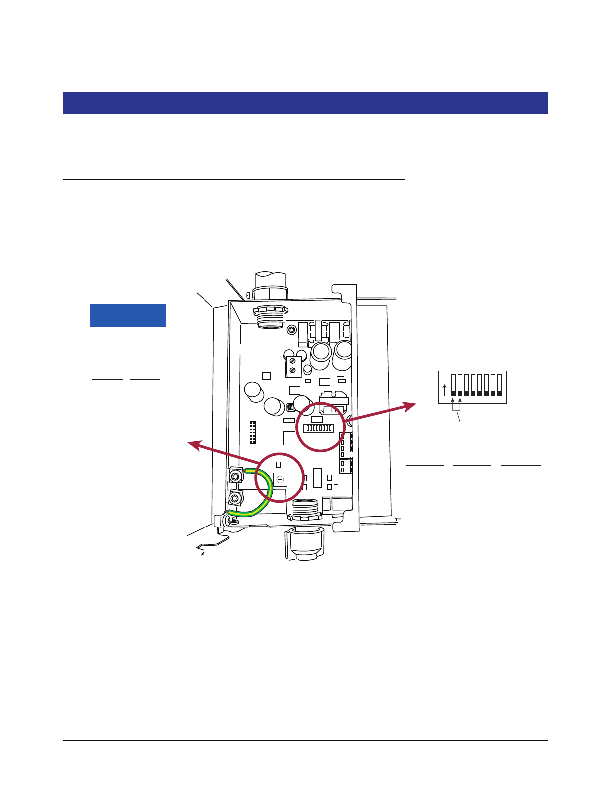
Appendix C: Device DIP Switch Settings
A
B
C
D
E
F
0
1
2
3
4
5
6
+
G
15V
G
AC
INPUT
REPEATER
RS-485
15V
TLS RF
S2
ON
TLS RF Device ID
0 = Master
Device Timeout
(Time to Probe Out/Comm alarm)
Sw Pos
Delay
0
1
2
3
4
5
6
7
8
9
A
B
C
D
E
F
5 m
10 m
15 m
20 m
30 m
45 m
60 m
90 m
2 h
3 h
4 h
6 h
8 h
12 h
18 h
24 h
off off
off on
1 - 8
9 - 16
Sw1 Sw2
Transmitter
IDs
0 (default)
1
Device ID
c-1.eps
Use this appendix for DIP switch settings for all devices in the site.
TLS RF Device Number Settings
The Dip Switch Locations to set the unique Device number for the TLS RF unit are shown in the Figure C-1. The
TLS RF that monitors the Receiver and transmitter IDs 1 - 8 is considered the site’s master TLS RF unit and must
have its Device ID set to 0 (default).
Figure C-1. TLS-RF switch settings
C-1
Page 47
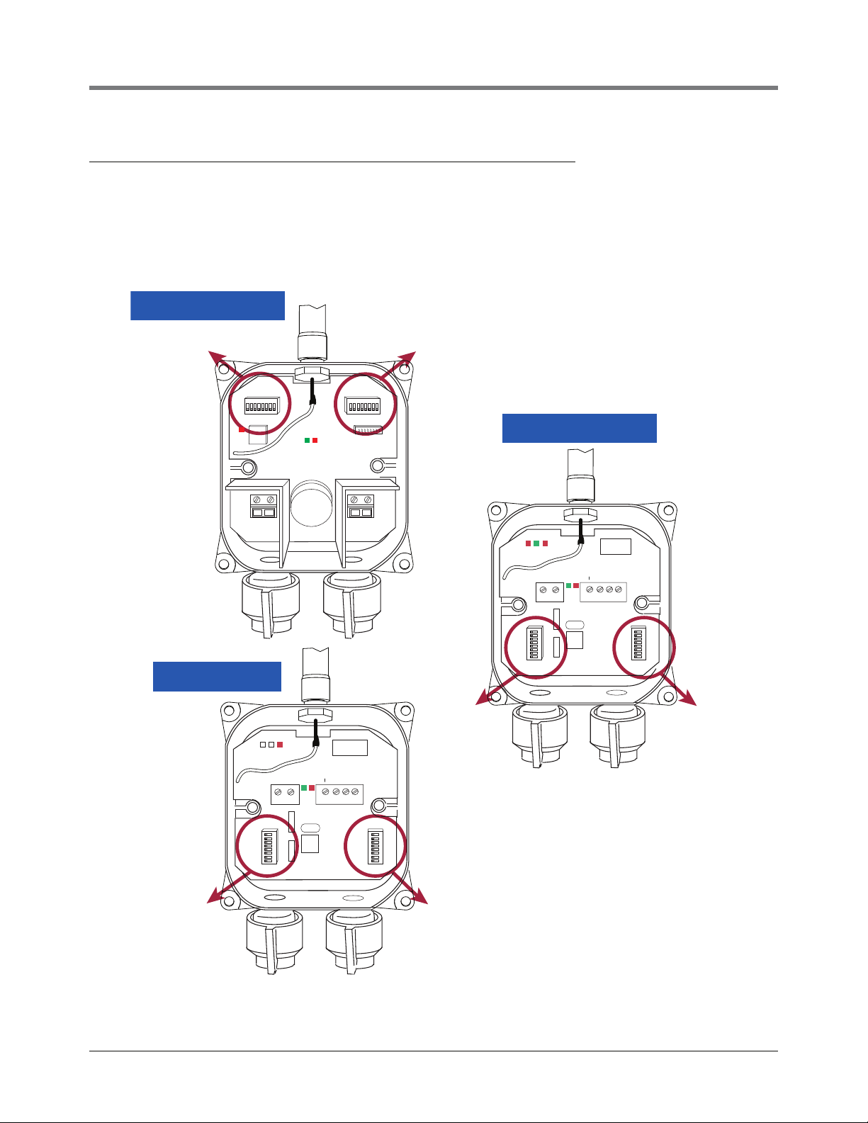
Appendix C: Device DIP Switch Settings Transmitter/Receiver/Repeater DIP Switch Settings
S1
S1
S2
S2
S1
S2
TRANSMITTER
REPEATER
RECEIVER
c-2.eps
S1
S2
PWR
GND
+IN
-IN
BATTERY
PROBE
REPEATER
J4
S2
S1
J3
RS-485
GND
+15V
+15v
+
GND
TRANSMIT
RECEIVE
PWR
REPEATER
J4
S2
S1
J3
RS-485
GND
+15V
+15v
+
GND
TRANSMIT
RECEIVE
PWR
Transmitter/Receiver/Repeater DIP Switch Settings
DIP switch locations for the Transmitter, Receiver and Repeater are shown in Figure C-2. Device DIP switch
settings for these devices are listed in Figure C-3 through Figure C-6 (use the appropriate settings for your
software version 1 or 3).
Figure C-2. DIP switch settings
C-2
Page 48

Appendix C: Device DIP Switch Settings Transmitter/Receiver/Repeater DIP Switch Settings
c-3.eps
1 2 3 900MHz Radio 869MHz Radio 900MHz Radio 869MHz Radio 900MHz Radio 869MHz Radio
OFF OFF OFF 30 30 Always Always Always Always
OFF OFF ON Do Not Set Do Not Set Do Not Set Do Not Set Do Not Set Do Not Set
OFF ON OFF 60 60 Do Not Set Do Not Set Do Not Set Do Not Set
OFF ON ON Do Not Set Do Not Set Do Not Set Do Not Set Do Not Set Do Not Set
ON OFF OFF 10 10 Do Not Set Do Not Set Do Not Set Do Not Set
ON OFF ON Do Not Set Do Not Set Do Not Set Do Not Set Do Not Set Do Not Set
ON ON OFF 240 240 Do Not Set Do Not Set Do Not Set Do Not Set
ON ON ON Do Not Set Do Not Set Do Not Set Do Not Set Do Not Set Do Not Set
1 2 3 900MHz Radio 869MHz Radio 900MHz Radio 869MHz Radio 900MHz Radio 869MHz Radio
OFF OFF OFF Do Not Set Do Not Set Do Not Set Do Not Set Do Not Set Do Not Set
OFF OFF ON Australia Italy Australia Italy Australia Italy
OFF ON OFF Do Not Set Do Not Set Do Not Set Do Not Set Do Not Set Do Not Set
OFF ON ON Do Not Set Do Not Set Do Not Set Do Not Set Do Not Set Do Not Set
ON OFF OFF Do Not Set Do Not Set Do Not Set Do Not Set Do Not Set Do Not Set
ON OFF ON Do Not Set Do Not Set Do Not Set Do Not Set Do Not Set Do Not Set
ON ON OFF Do Not Set Do Not Set Do Not Set Do Not Set Do Not Set Do Not Set
ON ON ON Do Not Set Do Not Set Do Not Set Do Not Set Do Not Set Do Not Set
RCVR
Version 1 (NA/EMEA)
Version 3 (Australia/Italy)
XMTR
RPTR
RCVR
S1: SW1-3
S1: SW1-3
XMTR: Diagnostic Time Out (Minutes)
RPTR
c-4.eps
45678
OFF OFF OFF OFF OFF
OFF OFF OFF OFF ON
OFF OFF OFF ON OFF
OFF OFF OFF ON ON
OFF OFF ON OFF OFF
OFF OFF ON OFF ON
OFF OFF ON ON OFF
OFF OFF ON ON ON
OFF ON OFF OFF OFF
OFF ON OFF OFF ON
OFF ON OFF ON OFF
OFF ON OFF ON ON
OFF ON ON OFF OFF
OFF ON ON OFF ON
OFFONONONOFF
OFFONONONON
ON OFF OFF OFF OFF
XMTR
RCVR
Version 1 and 3
Tank / Device Number
Do Not Set
(Unused)
Always
(Unused)
Always
S1: SW4~8
RPTR
1 (Master TLSRF Port 1)
2 (Master TLSRF Port 2)
3 (Master TLSRF Port 3)
4 (Master TLSRF Port 4)
5 (Master TLSRF Port 5)
6 (Master TLSRF Port 6)
7 (Master TLSRF Port 7)
8 (Master TLSRF Port 8)
9 (2nd TLSRF Port 1)
10 (2nd TLSRF Port 2)
11 (2nd TLSRF Port 3)
12 (2nd TLSRF Port 4)
13 (2nd TLSRF Port 5)
14 (2nd TLSRF Port 6)
15 (2nd TLSRF Port 7)
16 (2nd TLSRF Port 8)
Do Not Set
Do Not Set
Do Not Set
Do Not Set
Do Not Set
Do Not Set
Do Not Set
Do Not Set
Do Not Set
Do Not Set
Do Not Set
Do Not Set
Do Not Set
Do Not Set
Do Not Set
Do Not Set
Do Not Set
Do Not Set
Do Not Set
Do Not Set
Do Not Set
Do Not Set
Do Not Set
Do Not Set
Do Not Set
Do Not Set
Do Not Set
Do Not Set
Do Not Set
Do Not Set
Do Not Set
Do Not Set
Figure C-3. S1:DIP switches 1-3
Figure C-4. Device ID Settings - S1:DIP switches 4-8
C-3
Page 49

Appendix C: Device DIP Switch Settings Transmitter/Receiver/Repeater DIP Switch Settings
RPTR RCVR
No Change (Idle) Fall (Dispense) Rise (Delivery) No Change (Idle) Change (Leak)
1 2 3 4 Read/Tx Read/Tx Read/Tx Poll/Tx Poll/Tx ID VR Bus Address
OFF OFF OFF OFF 6/120 6/30 6/6 6/120 6/6 0 0
OFF OFF OFF ON 6/120 6/6 6/6 6/120 6/6 1 0
OFF OFF ON OFF 120/120 120/120 120/120 120/120 120/6 2 0
OFF OFF ON ON 600/600 600/600 600/600 600/600 600/6 3 0
OFF ON OFF OFF 3600/3600 3600/3600 3600/3600 3600/3600 3600/6 4 1
OFF ON OFF ON Do Not Set Do Not Set Do Not Set Do Not Set Do Not Set 5 1
OFF ON ON OFF Do Not Set Do Not Set Do Not Set Do Not Set Do Not Set 6 1
OFF ON ON ON Do Not Set Do Not Set Do Not Set Do Not Set Do Not Set 7 1
ON OFF OFF OFF Do Not Set Do Not Set Do Not Set Do Not Set Do Not Set 8 2
ON OFF OFF ON Do Not Set Do Not Set Do Not Set Do Not Set Do Not Set 9 2
ON OFF ON OFF Do Not Set Do Not Set Do Not Set Do Not Set Do Not Set 10 2
ON OFF ON ON Do Not Set Do Not Set Do Not Set Do Not Set Do Not Set 11 2
ON ON OFF OFF Do Not Set Do Not Set Do Not Set Do Not Set Do Not Set 12 3
ON ON OFF ON Do Not Set Do Not Set Do Not Set Do Not Set Do Not Set 13 3
ON ON ON OFF Do Not Set Do Not Set Do Not Set Do Not Set Do Not Set 14 3
ON ON ON ON Do Not Set Do Not Set Do Not Set Do Not Set Do Not Set 15 3
RPTR RCVR
No Change (Idle) Fall (Dispense) Rise (Delivery) No Change (Idle) Change (Leak)
1 2 3 4 Read/Tx Read/Tx Read/Tx Poll/Tx Poll/Tx ID VR Bus Address
OFF OFF OFF OFF 6/120 6/30 6/6 6/120 6/6 0 0
OFF OFF OFF ON 6/120 6/6 6/6 6/120 6/6 1 0
OFF OFF ON OFF 120/120 120/120 120/120 120/120 120/6 2 0
OFF OFF ON ON 600/600 600/600 600/600 600/600 600/6 3 0
OFF ON OFF OFF 3600/3600 3600/3600 3600/3600 3600/3600 3600/6 4 1
OFF ON OFF ON 6/120 6/30 6/6 6/120 6/6 5 1
OFF ON ON OFF 6/120 6/30 6/6 6/120 6/6 6 1
OFF ON ON ON 6/120 6/30 6/6 6/120 6/6 7 1
ON OFF OFF OFF 6/120 6/30 6/6 6/120 6/6 0 2
ON OFF OFF ON
ON OFF ON OFF
ON OFF ON ON
ON ON OFF OFF
ON ON OFF ON
ON ON ON OFF
ON ON ON ON
Reserved for future use
Reserved for future use
Reserved for future use
Mag Sump XMTR: Read/Transmit Interval
Mag Probe XMTR: Read/Transmit Interval
SystemID: Green Blinks = Software Version; Red Blinks- 1: 900MHz, 2:869MHz
RF Status: Green - On\Off with Radio power; Red: On during host to radio communication
Version 3 (Australia/Italy)
Version 1 (NA/EMEA)
S2: SW1~4
Mag Probe XMTR: Read/Transmit Interval
Mag Sump XMTR: Read/Transmit Interval
Reserved for future use
S2: SW1~4
Reserved for future use
*
*
*
*
* in seconds
Figure C-5. Mode Settings - S2:DIP switches 1-4
C-4
c-5.eps
Page 50

Appendix C: Device DIP Switch Settings Transmitter/Receiver/Repeater DIP Switch Settings
c-6.eps
5678
OFF OFF OFF OFF
OFF OFF OFF ON
OFF OFF ON OFF
OFF OFF ON ON
OFF ON OFF OFF
OFF ON OFF ON
OFF ON ON OFF
OFF ON ON ON
ON OFF OFF OFF
ON OFF OFF ON
ON OFF ON OFF
ON OFF ON ON
ON ON OFF OFF
ON ON OFF ON
ON ON ON OFF
ON ON ON ON
Version 1 and 3
S2: SW5~8
XMTR
RPTR
RCVR
Site ID
Site ID
Site ID
000
111
222
333
444
555
666
777
888
999
101010
14
111111
121212
151515
131313
14
14
Figure C-6. Site I D Settings - S2:DIP switches 5-8
C-5
Page 51

Appendix D: Lithium Battery Safety Data
This appendix contains the manufacturer supplied Transportation Certificate and Material Safety Data Sheet for the
lithium batteries used in the TLS RF Wireless System.
Lithium Battery Disposal Considerations
1. Waste disposal must be in accordance with the applicable regulations.
2. Disposal of the Lithium batteries should be performed by permitted, professional disposal firms
knowledgeable in Federal, State or Local requirements of hazardous waste treatment and hazardous waste
transportation.
3. Incineration should never be performed by battery users, but by trained professionals in an authorized facility
with proper gas and fume containment.
4. Recycling of battery can be done in authorized facility, through licensed waste carrier.
D-1
Page 52

Page 53

Material/Product Safety Data Sheet
(MSDS-PSDS)
LS/LSG/LSH/LST/LSX
products
single cells and multi-cell battery packs
Lithium/Thionyl chloride
Revision 8 Date 10/2008
1. Identification of the Substance or Preparation and Company
Product Primary Lithium/Thionyl chloride unit cells and multi-cell battery packs
)
2
Saft America Inc
313 Crescent Street
Valdese
NC 28690 – USA
Ph. :+1 828 874 4111
Fax :+1 828 874 2431
Saft Batteries Co., Ltd
Zhuhai Free Trade Zone
Lianfeng Road
Zhuhai 519030
Guangdong Province
China
Ph. : +86 756 881 9318
Fax : +86 756 881 9328
Production
sites
Saft Ltd.
River Drive
Tyne & Wear
South Shields
NE33 2TR – UK
Ph. :+44 191 456 1451
Fax :+44 191 456 6383
(Li-SOCl
Saft
Rue Georges Leclanché
BP 1039
86060 Poitiers cedex 9
France
Ph. :+33 (0)5 49 55 48 48
Fax :+33 (0)5 49 55 48 50
www.saftbatteries.com (section « Contact »)
Emergency contact +1 (703) 527 3887 (CHEMTREC US Service Center)
Within the USA +1 (800) 494 9300
2. Hazards Identification
Do not sh ort circuit, recharge puncture, incinerate, crush, immerse, force discharge or expose to temperatures
above the declared operating temperature range of product. Risk of fire or explosion.
The Lithi um-Thionyl chloride b atteries described in this
Safety Data Sheet are se aled units whi ch are not
hazardous when used according to the recommendations of the manufacturer.
Under normal conditions of use, the electrode materials and liq
uid electrolyte they contain are not exposed to the
outside, provi ded the batte ry integrity is maintained and se als remain intact. Risk of expo sure only in ca se of
abuse (mechanical, therm al, elect rical) which le ads to the activation of safety valves an d/or the ru pture of the
battery cont ainer. Ele ctrolyte leakag e, elect rode ma terials reaction with moi sture/water or b attery
vent/explosion/fire may follow, depending upon the circumstances.
3. Composition & Information on Ingredients
Ingredient Content CAS No. CHIP Classification
F; R14/15
Lithium
(Li)
3,5-5% 7439-93-2
R14/15, R21,R22, R35,
C; R14, R2
C; R34
R41, R43
S2, S8, S45
1, R22, R35,
R37, R41,R42/43
S2, S8, S24, S26, S36,
Thionyl chloride
(SOCl
)
2
40-46% 7719-09-7
S37, S45
MSDS Li-SOCl
Rev. 8 October 2008
2
Page 54

Aluminum chloride
anhydrou
(AlCl
s
)
3
Carbon
)
(C
n
1-5% 7446-70-0
3-4% 1333-86-4 NONE KNOWN
R14, R22, R37, R41, R43.
S2, S8, S22, S24, S26,
S36, S45
Amount varies depending on cell size.
4. First Aid Measures
Inhalation
Skin contact
Eye contact
Ingestion
Remove from exposure, rest and keep warm.
In severe cases obtain medical attention.
Wash off skin thoroughly with water. Remove contaminated clothing and
wa
sh before reuse. In severe cases obtain medical attention.
Irrigate thoroughly with water for at least 15 minutes.
Obtain medical attention.
Wash out mouth thoroughly with water and give plenty of water to drink.
Obtain medi
cal attention.
All cases of eye contamination, persistent skin irritation and casualties who
Further treatment
have swallo
wed this substance or been affected by breathing its vapours
should be seen by a doctor.
5. Fire Fighting Measures
CO extinguishers or, even preferably, copious quantities of water or water-based foam, can be used to cool
2
down burning Li-SOCl cells and batteries, as long as the extent of the fire ha s not progressed to the point
2
that the lithium metal they contain is exposed (marked by deep red flames).
Do not use for this purpose sand, dry powder or soda ash , graphite powder or fire blankets.
Use only metal (Class D) extinguishers on raw lithium.
Extinguishing media
Use water or CO
and class D fire extinguishing agent only on raw lithium.
on burning Li-SOCl2 cells or batteries
2
6. Accidental Release Measures
Remove personnel from area until fumes dissipate. Do not breathe vapours or touch liquid with bare hands.
If the skin has come into contact with the electrolyte, it should b
Sand or earth should be used to absorb any exuded material. Seal
e washed thoroughly with water.
leaking battery and contaminated
absorbent material in plastic bag and dispose of as Special Waste in accordance with local regulations.
MSDS Li-SOCl
Rev. 8 October 2008
2
Page 55

7. Handling and Storage
Handling
Storage
Other
Do not crush, pierce, short (+) and (-) battery terminals with conductive
(i.e. metal) goods. Do not directly heat o
r solder. Do not throw into fire.
Do not mix batteries of different types a nd brands. Do not mix new and u sed
batterie
s. Keep batteries in non conductive (i.e. plastic) trays.
Store in a cool (prefera bly belo w 3 0°C) and venti lated a rea, a way from
re, sources of heat, open flames, food and drink.
moistu
Keep adequate clearance between walls and batteries.
Temperature above 100°C may result in battery leaka
ge and rupture.
Since short circuit can cause b urn, l eakage an d ru pture ha zard, keep
batterie
s in original packaging until use and do not jumble them.
Lithium-Thionyl chlorid e b atteries a re not recha rgeable and should not be
tentatively charge
d.
Follow M anufacturers reco mmendations rega rding m aximum re commended
curre
nts and operating temperature range.
Applying pressure on deforming the battery may lead to disassembly
followe
d by eye, skin and throat irritation.
8. Exposure Controls & Personal Protection
Occupational
exposure standard
Respiratory
prote
ction
Compound
Sulfur dioxide
Hydrogen chloride
In all fire situations, use self-contained breathing apparatus.
Hand
prote
ction
In the event of leakage wear gloves.
Eye
protection
Safety glasses are recommended during handling.
Other
In the event of leakage, wear chemical apron.
9. Physical and Chemical Properties
Appearance
Odour
pH
Flash point
Flammability
Relative density
Solubility (water)
Solubility (other)
Cylindrical or prismatic shape
If leaking, gives off a pungent corrosive odour.
Not Applicable
Not applicable unless individual components exposed
Not applicable unless individual components exposed
Not applicable unless individual components exposed
Not applicable unless individual components exposed
Not applicable unless individual components exposed
8hr TWA
1 ppm
1 ppm
15min TWA
1 ppm
5 ppm
SK
-
-
MSDS Li-SOCl
Rev. 8 October 2008
2
Page 56
10. Stability and Reactivity
Product is stable under conditions described in Section 7.
Heat above 100 °C (150°C for th e LSH 20-15
Conditions to avoid.
assembled from them) or incinerate. Deform. Mutilate. Crush. Pierce. Disassemble
Recharge. Short circuit. Expose over a long period to humid conditions.
Materials to avoid
Oxidising agents, alkalis, water. Avoid electrolyte
Hydrogen (H
produced in case of reaction of lithium metal with water.
Chlorine ( Cl
Hazardous
decomposition
Products
case of thermal decomposition of thionyl chloride above 140°C.
Hydrochloric acid (HCl) and Sulfur dioxide (SO
Thionyl chloride with water at room temperature.
Hydrochloric acid (HCl) fumes, Lithium oxide, (Li
and Aluminum hydroxide (Al(OH)
Lithium tetrachloroaluminate (LiAlCl
11. Toxicological Information
None, unle ss battery ruptu res. In the e vent of expo sure to i nternal co ntents,
Signs & symptoms
corrosive fum
Overexposure can cause symptoms of non-fibrotic lung injury and membrane
irritation.
Inhalation
Skin contact
Eye contact
Ingestion
Medical conditions
generally aggravated
by exposure
Lung irritant.
Skin irritant
Eye irritant.
Tissue damage to throat and gastro-respiratory tract if swallowed.
In th e e vent o f e xposure to in ternal co ntents, eczema, skin a llergies, lung
injurie
12. Ecological Information
Mammalian effects
Eco-toxicity
Bioaccumulation
potential
Environmental fate
None known if used/disposed of correctly.
None known if used/disposed of correctly.
None known if used/disposed of correctly.
None known if used/disposed of correctly.
13. Disposal Considerations
0 cells and the batte ry pa cks
contact with aluminum or zinc.
) as well as Lithium oxide (Li2O) and Lithium hydroxide (Li OH) dust is
2
), Sulfur dioxi de (SO2) and Disulfur di chloride (S2Cl2) are p roduced in
2
) are produced in case of reaction of
2
O), Lithium hydroxide (LiOH)
2
) dust are produced in case of reaction of
3
) with water.
4
es will be very irritating to ski n, eyes and mucous m embranes.
s, asthma and other respiratory disorders may occur.
Do not incinerate, or subject cells to temperatures in excess of 100oC. Such abuse can result in loss of
seal, leakage, and/or cell explosion. Dispose of in accordan
ce with appropriate local regulations.
MSDS Li-SOCl
Rev. 8 October 2008
2
Page 57

14. Transport Information
Label for conveyance
UN numbers
Shipping names
Hazard classification
Packing group
Specific
dispositions
IMDG Code
CAS
EmS No.
Marine pollutant
ADR Class
15. Regulatory Information
Risk phrases
Safety phrases
For the single cell batteries and multi-cell battery packs that are n
on-restricted to
transport (non-assigned to the Miscellaneous Class 9), use lithium batteries
inside label.
For the single cell batteries and multi-cell battery packs which are restricted to
transpo
rt (assigned to Class 9), use Class 9 Miscellaneous Dangerous Goods
and UN Identification Number labels.
In all cases, refer to the product transport certificate issued by the
UN3090 (shipment of cells and batteries in bulk
UN 3091 (cells and batteries co
ntained in equipment or packed with it)
)
Manufacturer.
Lithium Metal Batteries
Depending on their lithium metal content, some single cells and small multi-cell
battery packs may be non-
assigned to Class 9 (Refer to Transport Certificate)
II
IATA: A45, A88, A99, P968, P969, P970
IMDG: 188, 230, 310, P903
ADR/RID: 188, 230, 310, 6
36, P903, P903a
3090 (Li Batteries) 3091 (Li Batteries contained in equipment or packed with it)
F-A, S-I
No
Class9
Lithium
(Li)
Thionyl
chloride
(SOCl
)
2
Aluminum
chloride
anhydrous
)
(AlCl
3
Lithium
(Li)
Thionyl
chloride
(SOCl
)
2
R14/15
R21
R22
R35
R41
R42/4
R14
R22
R35
R37
R41
R42/43
R14
R22
R37
R41
R43
S2
S8
S45
S2
S8
S24
S26
S36
S37
S45
Reacts violently with water, liberating extremely
flammable g
ases.
Harmful in contact with skin.
Harmful if swallowed.
Causes burns.
Risk of serious damage to eye.
May cause sensitization by inhalation and skin
3
conta
ct.
Reacts with water.
Harmful if swallowed.
Causes burns.
Irritating to respiratory system.
Risk of serious damage to eye.
May cause sensitization by inhalation and skin
ct.
conta
Reacts with water.
Harmful if swallowed.
Irritating to respiratory system.
Risk of serious damage to eye.
May cause sensitization by skin contact.
Keep out of reach of children
Keep away from moisture
In case of incident, seek medical attention.
Keep out of reach of children.
Keep away from moisture.
Avoid contact with skin.
In case of contact with eyes, rinse immediately with
plenty of water.
Wear suitable protective clothing.
Wear suitable gloves.
In case of incident, seek medical attention.
MSDS Li-SOCl
Rev. 8 October 2008
2
Page 58

Aluminum
chloride
anhydrou
(AlCl
s
)
3
S2
S8 S22
S24 S26
S36
UK
regulatory references
16. Other Information
This info rmation ha s been compile d fro m sou rces considered to be depe ndable and i s, to the best of our
knowledge a nd belief, accurate an d reliable a s of the date com piled. Ho wever, no representation, wa rranty
(either expressed or im plied ) or guarantee i s made to the accuracy, re liability or com pleteness of the
information contained herein.
Keep out of reach of children.
Keep away from moisture.
Do not breathe dust.
Avoid contact with skin.
In case of contact with eyes, rinse immediately with
plenty of water.
Wear suitable protective clothing.
Classified under CHIP
This info rmation rel ates to the spe cific materials de signated a nd may not be valid for such material u sed in
combi
nation with any other materials or in any process. It is the user’s responsibility to satisfy himself as to the
suitability and completeness of this information for his particular use.
Saft does not accept lia bility for any lo ss or damage that may o
ccur, whether direct, in direct, inci dental or
consequential, from the use of this information. Saft does not offer warranty against patent infringement.
Signature
Alain Kerouanton
Lithium Product Manager
MSDS Li-SOCl
Rev. 8 October 2008
2
Page 59

For technical support, sales or
other assistance, please visit:
www.veeder.com
 Loading...