

Page 1

System Setup Manual
TLS-3XX Series Consoles
Manual No: 576013-623 • Revision: AM
Software Version X33
Page 2

Notice
Veeder-Root makes no warranty of any kind with regard to this publication, including, but not limited to, the implied warranties of
merchantability and fitness for a particular purpose.
Veeder-Root shall not be liable for errors contained herein or for incidental or consequential damages in connection with the
furnishing, performance, or use of this publication.
Veeder-Root reserves the right to change system options or features, or the information contained in this publication.
This publication contains proprietary information which is protected by copyright. All rights reserved. No part of this publication
may be modified or translated to another language without the prior written consent of Veeder-Root.
Contact TLS Systems Technical Support for additional troubleshooting information at 800-323-1799.
DAMAGE CLAIMS / LOST EQUIPMENT
Thoroughly examine all components and units as soon as they are received. If any cartons are damaged or missing, write a
complete and detailed description of the damage or shortage on the face of the freight bill. The carrier's agent must verify the
inspection and sign the description. Refuse only the damaged product, not the entire shipment.
Veeder-Root must be notified of any damages and/or shortages within 30 days of receipt of the shipment, as stated in our Terms
and Conditions.
VEEDER-ROOT’S PREFERRED CARRIER
1. Contact Veeder-Root Customer Service at 800-873-3313 with the specific part numbers and quantities that were missing
or received damaged.
2. Fax signed Bill of Lading (BOL) to Veeder-Root Customer Service at 800-234-5350.
3. Veeder-Root will file the claim with the carrier and replace the damaged/missing product at no charge to the customer.
Customer Service will work with production facility to have the replacement product shipped as soon as possible.
CUSTOMER’S PREFERRED CARRIER
1. It is the customer’s responsibility to file a claim with their carrier.
2. Customer may submit a replacement purchase order. Customer is responsible for all charges and freight associated with
replacement order. Customer Service will work with production facility to have the replacement product shipped as soon as
possible.
3. If “lost” equipment is delivered at a later date and is not needed, Veeder-Root will allow a Return to Stock without a restocking
fee.
4. Veeder-Root will NOT be responsible for any compensation when a customer chooses their own carrier.
RETURN SHIPPING
For the parts return procedure, please follow the appropriate instructions in the "General Returned Goods Policy” pages in the
"Policies and Literature" section of the Veeder-Root North American Environmental Products price list. Veeder-Root will not
accept any return product without a Return Goods Authorization (RGA) number clearly printed on the outside of the package.
©Veeder-Root 2014. All rights reserved
.
Page 3

1 Introduction
Contractor Certification Requirements ...........................................................................1-1
Related Manuals ............................................................................................................1-1
Safety Precautions .........................................................................................................1-2
Safety Warnings ............................................................................................................1-2
2 Front Panel Keypads
Arrangement of Keys .....................................................................................................2-1
Operating Keys......................................................................................................2-1
Alphanumeric Keys................................................................................................2-1
Blue Key (Maintenance Tracker - TLS-350 Only)..................................................2-2
White Key (Maintenance Report - TLS-350 Only).................................................2-2
Using the Operating Keys ..............................................................................................2-2
Using the Alphanumeric Keys ........................................................................................2-3
Entering Alphanumeric Data..................................................................................2-4
Special Characters and Cursor Movement............................................................2-4
3 Setup Mode Organization
Functions .......................................................................................................................3-1
Steps ..............................................................................................................................3-1
Setup Mode Programming Table ...................................................................................3-1
Table of Contents
4 Prior to Applying AC Power to the Console
Security Code Enable/Disable .......................................................................................4-1
TLS-300 Consoles.................................................................................................4-1
TLS-350 Consoles.................................................................................................4-1
Battery Backup ..............................................................................................................4-6
Applying AC Power to the Console ................................................................................4-6
5 System Setup
Programming Guidelines ...............................................................................................5-1
Automatic Return to Operating Mode ............................................................................5-1
Setup Data Warning ......................................................................................................5-1
Printing a Setup Data Report .........................................................................................5-1
Selecting the System Setup Function ............................................................................5-2
System Language ..........................................................................................................5-2
System Units ..................................................................................................................5-2
Setting the Date and Time Format .................................................................................5-3
Current Date ..................................................................................................................5-3
Current Time ..................................................................................................................5-4
Report Headers .............................................................................................................5-4
Shift Start Times ............................................................................................................5-4
Shift BIR Printouts .........................................................................................................5-5
Daily BIR Printouts .........................................................................................................5-5
Ticketed Delivery ...........................................................................................................5-5
TC Ticketed Delivery .....................................................................................................5-6
Close Day of Week ........................................................................................................5-6
Variance Reports ...........................................................................................................5-6
Daily Delivery Variance Reports............................................................................5-6
Weekly Delivery Variance Reports ........................................................................5-6
Periodic Delivery Variance Reports.......................................................................5-7
iii
Page 4

Table of Contents
Daily Book Variance Reports.................................................................................5-7
Weekly Book Variance Reports.............................................................................5-7
Periodic Book Variance Reports............................................................................5-7
Daily Variance Analysis Reports ...........................................................................5-7
Weekly Variance Analysis Reports........................................................................5-7
Periodic Variance Analysis Reports ......................................................................5-8
Tank Periodic Test Needed Warnings ...........................................................................5-8
Enable Tank Periodic Test Needed Warnings and Alarms ...................................5-8
Disable Tank Periodic Test Needed Warnings......................................................5-9
Tank Annual Test Needed Warnings .............................................................................5-9
Enable Tank Annual Test Needed Warnings and Alarms .....................................5-9
Disable Tank Annual Test Needed Warnings and Alarms ..................................5-10
Line Re-Enable Method ...............................................................................................5-10
Line Periodic Test Needed Warnings ..........................................................................5-10
Enable Line Periodic Test Needed Warnings and Alarms...................................5-11
Disable Line Periodic Test Needed Warnings .....................................................5-11
Line Annual Test Needed Warnings ............................................................................5-11
Enable Line Annual Test Needed Warnings and Alarms ....................................5-12
Disable Line Annual Test Needed Warnings and Alarms....................................5-12
Remote Printer Page Eject ..........................................................................................5-13
Print TC Volumes .........................................................................................................5-13
Temperature Compensation Value ..............................................................................5-13
Tanker Load Report - International Option ..................................................................5-14
Stick Height Offset - International Option ....................................................................5-14
Ullage ...........................................................................................................................5-14
H-Protocol Data Format - International Option ............................................................5-14
Precision Test Duration (PLLD/WPLLD Only) .............................................................5-15
Precision Line Test Auto-Confirm ................................................................................5-15
Daylight Savings Time .................................................................................................5-16
Re-direct Local Printout ...............................................................................................5-16
QPLD Monthly Printout - International Option ..............................................................5-17
Euro Protocol Prefix .....................................................................................................5-17
BDIM Trans Alarm Delay .............................................................................................5-17
System Security Code .................................................................................................5-17
Maintenance History ....................................................................................................5-18
Tank Chart Security .....................................................................................................5-18
Custom Alarm Labels ..................................................................................................5-19
Service Notice (TLS-350 Consoles Only) ....................................................................5-27
Inventory Alarms Threshold Units ................................................................................5-28
System Beeper ............................................................................................................5-29
Mass/Density ...............................................................................................................5-30
Fiscal Height Security ..................................................................................................5-30
Alarm Reduction ..........................................................................................................5-31
6 Communications Setup
Selecting the Communications Setup Function .............................................................6-1
Port Settings ..................................................................................................................6-1
Note: Port Settings - International Installations With SiteLink modems.................6-1
Baud Rate..............................................................................................................6-1
Parity .....................................................................................................................6-2
Stop Bit ..................................................................................................................6-2
Data Length...........................................................................................................6-2
Dial Type ...............................................................................................................6-3
iv
Page 5

Table of Contents
Answer On.............................................................................................................6-3
Security Code........................................................................................................6-3
Setting the Modem Type (international Installations) ............................................6-4
Modem Setup String..............................................................................................6-4
Dial Tone Interval ..................................................................................................6-4
DTR Normal State .................................................................................................6-4
Specifying Port Settings for Additional Communication Modules..........................6-5
Continue Communications Setup..........................................................................6-5
Auto-Transmit Setup (RS-232 or RS-232/RS-485 Modules Only) .................................6-5
Auto-Transmit Method...........................................................................................6-5
Auto Delay Time ....................................................................................................6-6
Auto Repeat Time..................................................................................................6-6
Continue Communications Setup..........................................................................6-6
Phone Directory Setup ...................................................................................................6-7
Receiver Configuration ..........................................................................................6-7
Receiver Location..................................................................................................6-7
Receiver Telephone Number.................................................................................6-7
Select Modem........................................................................................................6-8
Receiver Type .......................................................................................................6-8
Retry Number ........................................................................................................6-8
Retry Delay Time...................................................................................................6-9
Confirmation Report ..............................................................................................6-9
Setting Up Additional Phone Numbers ..................................................................6-9
Continue Communications Setup..........................................................................6-9
Auto-Dial Setup ............................................................................................................6-10
Receiver Report List ............................................................................................6-10
Auto Dial Method: All Phones/Single Phone .......................................................6-11
Auto-Dial Frequency: Specific Date.....................................................................6-11
Auto-Dial Frequency: Annually............................................................................6-12
Auto-Dial Frequency: Monthly .............................................................................6-13
Auto-Dial Frequency: Weekly..............................................................................6-13
Auto-Dial Frequency: Daily..................................................................................6-14
Auto-Dial Frequency: BIR End ............................................................................6-14
Setting Up the Frequency for Additional Receivers
(Single Phone Only) ............................................................................................6-15
Continue Communications Setup........................................................................6-15
Auto-Dial Alarm Setup .................................................................................................6-15
In-Tank Alarms ....................................................................................................6-16
Remaining Alarm Groups ....................................................................................6-17
Liquid Sensor Alarms ..........................................................................................6-17
Vapor Sensor Alarms ..........................................................................................6-17
External Inputs Alarms ........................................................................................6-17
Line Leak Alarms (VLLD) ....................................................................................6-17
Groundwater Sensor Alarms ...............................................................................6-17
2 Wire C.L. Sensor Alarms ..................................................................................6-18
3 Wire C.L. Sensor Alarms ..................................................................................6-18
Receiver Alarms ..................................................................................................6-18
Power Side DIM Alarms ......................................................................................6-18
Reconciliation Alarms ..........................................................................................6-18
Pressure Line Leak Detector (PLLD) Alarms ......................................................6-18
Wireless Pressure Line Leak Detector (WPLLD) Alarms ....................................6-19
Communication Side DIM Alarms........................................................................6-19
Smart Sensor Alarms ..........................................................................................6-19
Pump Relay Monitor Alarm..................................................................................6-19
VMCI Dispenser Interface Alarms .......................................................................6-19
VMC Alarms ........................................................................................................6-19
v
Page 6

Setting Up Auto-Dial Alarms for Additional Destinations .....................................6-20
RS-232 End of Message ..............................................................................................6-20
7 In-Tank Setup
Selecting the In-Tank Setup Function ............................................................................7-1
Tank Configuration ........................................................................................................7-1
How the System Configures In-Tank Probes ........................................................7-1
Specifying In-Tank Probe Positions.......................................................................7-1
Product Labels ...............................................................................................................7-2
Product Code .................................................................................................................7-2
Coefficient of Thermal Expansion ..................................................................................7-3
Tank Density ..................................................................................................................7-4
Tank Diameter ...............................................................................................................7-5
Tank Profile ....................................................................................................................7-5
Tank Profile Selections..........................................................................................7-5
Procedure ..............................................................................................................7-6
Full Volume ....................................................................................................................7-6
4 or 20 Point Tank Profiles Height/Volume Entries ...............................................7-7
50 Point Tank Profile Height/Volume Entries (Tank Chart Security Disabled) ......7-7
50 Point Tank Profile Entries With Tank Chart Security Enabled..........................7-9
Meter Data Present ......................................................................................................7-11
Vapor Loss Factor - International Option .....................................................................7-11
End Factor ...................................................................................................................7-12
Calibration Update .......................................................................................................7-12
Float Size .....................................................................................................................7-13
Water Warning .............................................................................................................7-14
High Water Limit ..........................................................................................................7-15
Water Alarm Filter ........................................................................................................7-15
Programmable Minimum Water Threshold ..................................................................7-16
Max or Label Vol ..........................................................................................................7-16
Overfill Limit .................................................................................................................7-16
High Product ................................................................................................................7-17
Delivery Limit ...............................................................................................................7-17
Low Product .................................................................................................................7-17
Leak Alarm Limit ..........................................................................................................7-18
Sudden Loss Limit .......................................................................................................7-18
Tank Tilt .......................................................................................................................7-18
Calculating Tank Tilt (H2)....................................................................................7-19
Entering the Tank Tilt Value ................................................................................7-19
Probe Offset .................................................................................................................7-20
Siphon Manifolded Tank Status ...................................................................................7-20
Line Manifolded Tank Status .......................................................................................7-21
Leak Minimum Periodic ...............................................................................................7-21
Leak Minimum Annual .................................................................................................7-22
Periodic Test Type .......................................................................................................7-22
Annual Test Fail ...........................................................................................................7-22
Periodic Test Fail .........................................................................................................7-23
Gross Test Fail ............................................................................................................7-23
Annual Test Averaging ................................................................................................7-23
Periodic Test Averaging ...............................................................................................7-24
Tank Test Notify ...........................................................................................................7-24
Tank Test Siphon Break ..............................................................................................7-24
Table of Contents
vi
Page 7

Stick Offset (International Option) ................................................................................7-24
HRM Reconciliation Warning Limit (International Option) ............................................7-25
HRM Reconciliation Alarm Limit (international Option) ................................................7-25
Delivery Report Delay Time .........................................................................................7-26
Pump Threshold ..........................................................................................................7-26
Setting Up Additional Tanks ........................................................................................7-26
8 In-Tank Leak Tests
Selecting the In-Tank Leak Test Setup Function ...........................................................8-1
Leak Test Method: All Tank/Single Tank .......................................................................8-1
Leak Test Frequency .....................................................................................................8-2
Test On Date .........................................................................................................8-2
Annual Test ...........................................................................................................8-3
Monthly Test ..........................................................................................................8-3
Weekly Test...........................................................................................................8-4
Daily Test...............................................................................................................8-4
Automatic Test.......................................................................................................8-4
CSLD - Option .......................................................................................................8-5
Gross Test Auto-Confirm ...............................................................................................8-7
Leak Test Start Time .....................................................................................................8-7
Leak Test Rate ..............................................................................................................8-7
Leak Test Duration ........................................................................................................8-8
Leak Test Early Stop .....................................................................................................8-8
CSLD Report Only .........................................................................................................8-9
Leak Test Report Format ...............................................................................................8-9
Setting Up Additional Tanks ..........................................................................................8-9
Table of Contents
9 Fuel Management
Selecting the Fuel Management Function .....................................................................9-1
Delivery Warning Days ..................................................................................................9-1
Daily Time to Print Fuel Management Report ................................................................9-1
Average Daily Sales ......................................................................................................9-2
10 Pressurized Line Leak Detection
Line Manifolding Implications for AccuChart ................................................................10-1
PLLD Setup .................................................................................................................10-1
Activating PLLDs .........................................................................................................10-1
Labeling PLLDs ...........................................................................................................10-1
Piping Type ..................................................................................................................10-2
Piping Length ...............................................................................................................10-2
Entering Line Length for Dual Size Flexible Pipe Types .....................................10-3
Entering Line Length for 2.0/3.0 In. Fiberglass Pipe Type ..................................10-3
User Defined Pipe Type - Setup Parameters ...............................................................10-3
Thermal Coefficient ......................................................................................................10-4
0.2 gph (0.76 lph) Line Leak Test Scheduling .............................................................10-4
0.1 gph (0.38 lph) Line Leak Test Scheduling .............................................................10-5
Passive 0.1 gph Line Leak Testing ..............................................................................10-5
Shutdown Rate ............................................................................................................10-6
Low Pressure Alarm Shutoff ........................................................................................10-6
Tank Selection .............................................................................................................10-7
Selecting a Dispense Mode .........................................................................................10-7
Auto Active Switchover........................................................................................10-8
Pressure Transducer Type ..........................................................................................10-8
vii
Page 8

Pressure Offset ............................................................................................................10-9
Venting The Line .................................................................................................10-9
Determining a Pressure Offset Value for each Transducer...............................10-10
Entering the Pressure Offset Value for each Transducer..................................10-10
Mechanical Blenders .................................................................................................10-11
Setting Up Additional PLLDs .....................................................................................10-11
11 Wireless Pressurized Line Leak Detection
Line Manifolding Implications for AccuChart ................................................................11-1
WPLLD Setup ..............................................................................................................11-1
Activating WPLLDs ......................................................................................................11-1
Labeling WPLLDs ........................................................................................................11-2
Piping Type ..................................................................................................................11-2
Piping Length ...............................................................................................................11-2
0.2 gph (0.76 lph) Line Leak Test Scheduling - Option ...............................................11-3
0.1 gph (0.38 lph) Line Leak Test Scheduling - Option ...............................................11-4
Shutdown Rate ............................................................................................................11-4
Pressure Offset ............................................................................................................11-4
Venting The Line .................................................................................................11-5
Determining a Pressure Offset Value for each Transducer.................................11-5
Entering the Pressure Offset Value for each Transducer....................................11-6
Tank Selection .............................................................................................................11-6
Selecting a Dispense Mode .........................................................................................11-6
Setting Up Additional WPLLDs ....................................................................................11-7
Table of Contents
12 Volumetric Line Leak Detection
VLLD Setup .................................................................................................................12-1
Activating VLLDs .........................................................................................................12-1
Pipe Label and Tank Identification ...............................................................................12-1
Enter Dispense Mode ..................................................................................................12-2
Fuel Type .....................................................................................................................12-3
Piping Length and Type ...............................................................................................12-3
Pump Pressure ............................................................................................................12-4
Shutdown Rate ............................................................................................................12-5
Pumpside Test .............................................................................................................12-5
Wait Mode ....................................................................................................................12-6
New Blender Protocol (NBP) Partner ...........................................................................12-6
Last Annual Test Passed .............................................................................................12-7
Setting Up Additional Line Leak Detectors ..................................................................12-7
13 Volumetric Line Leak Tests
Selecting the Line Leak Test Setup Function ..............................................................13-1
Leak Test Setup Method: All Lines/Single Lines .........................................................13-1
Leak Test Frequency ...................................................................................................13-2
On Date ...............................................................................................................13-2
Annual Test .........................................................................................................13-2
Monthly Test ........................................................................................................13-3
Weekly Test.........................................................................................................13-3
Daily Test.............................................................................................................13-4
Leak Test Start Time ...................................................................................................13-4
Leak Test Rate ............................................................................................................13-4
Setting Up Additional Lines ..........................................................................................13-5
viii
Page 9

14 Line Leak Test Lockout
Selecting the Line Leak Test Lockout Function ...........................................................14-1
Lockout Schedule ........................................................................................................14-1
Daily Schedule .............................................................................................................14-1
Individual Schedules ....................................................................................................14-2
Entering Additional Test Lockout Schedules ...............................................................14-3
15 Pump Sense Setup
Selecting the Pump Sense Function ............................................................................15-1
Pump Sense Configuration ..........................................................................................15-1
How the System Configures Pump Sense Modules............................................15-1
Specifying Pump Sense Positions.......................................................................15-1
Pump Sense Tank Number .........................................................................................15-2
Pump Sense Dispense Mode ......................................................................................15-2
Auto Active Switchover........................................................................................15-3
16 Pump Relay Monitor Setup
Selecting the Pump Relay Monitor Function ................................................................16-1
Pump Relay Monitor Configuration ..............................................................................16-1
How the System Configures Pump Relay Monitor Modules ................................16-1
Specifying Pump Relay Monitor Positions...........................................................16-1
Labeling Pump Relay Monitors ....................................................................................16-2
Pump Relay Monitor Relay Input .................................................................................16-2
Pump Relay Monitor Delay Input .................................................................................16-2
Table of Contents
17 Reconciliation Setup
Dispenser Module Data String .....................................................................................17-1
Automatic Daily Closing ...............................................................................................17-1
Automatic Shift Closing ................................................................................................17-2
Periodic Reconciliation Mode ......................................................................................17-2
Periodic Reconciliation Alarm ......................................................................................17-3
Remote Report Format ................................................................................................17-4
Temp Compensation ...................................................................................................17-4
Meter Calibration Offset ...............................................................................................17-5
Modify Tank/Meter Map ...............................................................................................17-5
18 Liquid Sensor Setup
Selecting the Liquid Sensor Setup Function ................................................................18-1
Liquid Sensor Configuration ........................................................................................18-1
How the System Configures Liquid Sensors .......................................................18-1
Specifying Liquid Sensor Positions .....................................................................18-1
Liquid Sensor Location ................................................................................................18-2
Liquid Sensor Type ......................................................................................................18-2
Liquid Sensor Category (RS-232 and Remote Display) ..............................................18-3
Setting Up Additional Liquid Sensors ..........................................................................18-3
19 Vapor Sensor Setup
Selecting the Vapor Sensor Setup Function ................................................................19-1
Vapor Sensor Configuration ........................................................................................19-1
How the System Configures Vapor Sensors .......................................................19-1
Specifying Vapor Sensor Positions .....................................................................19-1
Vapor Sensor Location ................................................................................................19-2
Vapor Threshold ..........................................................................................................19-2
ix
Page 10

Before You Begin ................................................................................................19-2
Specifying Vapor Threshold Levels .....................................................................19-3
Vapor Sensor Category ...............................................................................................19-3
Setting Up Additional Vapor Sensors ..........................................................................19-4
20 Groundwater Sensor Setup
Selecting the Groundwater Sensor Setup Function .....................................................20-1
Groundwater Sensor Configuration .............................................................................20-1
How the System Configures Groundwater Sensors............................................20-1
Specifying Groundwater Sensor Positions ..........................................................20-1
Groundwater Sensor Location .....................................................................................20-2
Groundwater Sensor Category ....................................................................................20-2
Setting Up Additional Groundwater Sensors ...............................................................20-2
21 2-Wire C.L. Sensor Setup
Selecting the 2-Wire C.L. Sensor Setup Function .......................................................21-1
2-Wire C.L. Sensor Configuration ................................................................................21-1
How the System Configures 2-Wire C.L. Sensors...............................................21-1
Specifying 2-wire C.L. Sensor Positions..............................................................21-1
2-Wire C.L. Sensor Location ........................................................................................21-2
2-Wire C.L. Sensor Type .............................................................................................21-2
2-Wire C.L. Sensor Category .......................................................................................21-2
Setting Up Additional 2-Wire C.L. Sensors ..................................................................21-3
Table of Contents
22 3-Wire C.L. Sensor Setup
Selecting the 3-Wire C.L. Sensor Setup Function .......................................................22-1
3-Wire C.L. Sensor Configuration ................................................................................22-1
How the System Configures 3-Wire C.L. Sensors...............................................22-1
Specifying 3-Wire C.L. Sensor Positions.............................................................22-1
3-Wire C.L. Sensor Location ........................................................................................22-2
3-Wire C.L. Sensor Mode ............................................................................................22-2
3-Wire C.L. Sensor Category .......................................................................................22-2
Setting Up Additional 3-Wire C.L. Sensors ..................................................................22-3
23 External Input Setup
Selecting the External Input Setup Function ................................................................23-1
External Input Configuration ........................................................................................23-1
How the System Configures Input Devices .........................................................23-1
Specifying Input Positions ...................................................................................23-1
External Input Name ....................................................................................................23-2
External Input Type ......................................................................................................23-2
Switch Orientation ........................................................................................................23-3
External Input Emergency Generator Data ..................................................................23-3
Pump Sense Setup Data .............................................................................................23-4
Selecting a Dispense Mode.................................................................................23-4
Auto Active Switchover........................................................................................23-5
Setting Up Additional Inputs ........................................................................................23-5
24 Output Relay Setup
Selecting the Output Relay Setup Function .................................................................24-1
Relay Configuration .....................................................................................................24-1
How the System Configures Output Relays ........................................................24-1
Specifying Output Relay Positions ......................................................................24-1
x
Page 11

Table of Contents
Relay Designation ........................................................................................................24-2
Selecting Relay Type ...................................................................................................24-2
Assignment Method .....................................................................................................24-3
In-Tank Alarms ....................................................................................................24-3
Remaining Alarm Groups ....................................................................................24-5
Liquid Sensor Alarms ..........................................................................................24-5
Vapor Sensor Alarms ..........................................................................................24-5
External Inputs Alarms ........................................................................................24-5
Line Leak Alarms (VLLD) ....................................................................................24-5
Groundwater Sensor Alarms ...............................................................................24-5
2 Wire C.L. Sensor Alarms ..................................................................................24-6
3 Wire C.L. Sensor Alarms ..................................................................................24-6
Power Side DIM Alarms ......................................................................................24-6
Reconciliation Alarms ..........................................................................................24-6
Pressure Line Leak Detector (PLLD) Alarms ......................................................24-6
Wireless Pressure Line Leak Detector (WPLLD) Alarms ....................................24-6
Communication Side DIM Alarms........................................................................24-7
Smart Sensor Alarms ..........................................................................................24-7
Pump Relay Monitor Alarm..................................................................................24-7
VMCI Dispenser Interface Alarms .......................................................................24-7
VMC Alarms ........................................................................................................24-7
Setting Up Additional Relays .......................................................................................24-8
25 Line Disable Setup
Selecting the PLLD, WPLLD, or VLLD Line Disable Setup Function ...........................25-1
Alarm Assignment Notes.....................................................................................25-1
In-Tank Alarms ............................................................................................................25-1
Remaining Alarm Groups ....................................................................................25-2
Liquid Sensor Alarms ..........................................................................................25-3
Vapor Sensor Alarms ..........................................................................................25-3
External Input Alarms ..........................................................................................25-3
Line Leak Alarms.................................................................................................25-3
Groundwater Sensor Alarms ...............................................................................25-3
2 Wire C.L. Sensor Alarms ..................................................................................25-3
3 Wire C.L. Sensor Alarms ..................................................................................25-4
Power Side DIM Alarms ......................................................................................25-4
Reconciliation Alarms ..........................................................................................25-4
Pressure Line Leak Detector (PLLD) Alarms ......................................................25-4
Wireless Pressure Line Leak Detector (WPLLD) Alarms ....................................25-4
Communication Side DIM Alarms........................................................................25-5
Smart Sensor Alarms ..........................................................................................25-5
Pump Relay Monitor Alarm..................................................................................25-5
VMCI Dispenser Interface Alarms .......................................................................25-5
VMC Alarms ........................................................................................................25-5
Setting Up Additional Disables ....................................................................................25-6
26 Smart Sensor Setup
Selecting the Smart Sensor Setup Function ................................................................26-1
Sensor Configuration ...................................................................................................26-1
Smart Sensor Label .....................................................................................................26-2
Selecting Sensor Category ..........................................................................................26-2
Mag Sensor Setup .......................................................................................................26-3
Vac Sensor Setup ........................................................................................................26-4
xi
Page 12

27 VMC Setup
Selecting the VMC Setup Function ..............................................................................27-1
Add a VMC Serial Number ..........................................................................................27-1
Edit a VMC Serial Number ...........................................................................................27-1
Remove a VMC Serial Number ....................................................................................27-2
28 Archive Utility
Accessing the Archive Utility Function .........................................................................28-1
Archiving Setup Data ...................................................................................................28-1
Restoring Archived Setup Data ...................................................................................28-2
Clearing Archived Setup Data .....................................................................................28-3
Table of Contents
Figures
Tables
Appendix A: Calculating Tank Tilt - International
Entering the Tank Tilt Value ................................................................................. A-3
Appendix B: Setup Parameters for TLS-300 System - International
System Setup ...............................................................................................................B-1
Comm Board (1, 2, etc.) Setup ..................................................................................... B-2
In-Tank Setup ............................................................................................................... B-2
Leak Test Method Setup ............................................................................................... B-3
Appendix C: Setup Parameters for TLS-350 System - International
Figure 4-1. Battery Backup Switch and DIP Switch Location - TLS-300
Console ................................................................................................4-3
Figure 4-2. Battery Backup Switch and DIP Switch Location TLS-350
Consoles with CPU Board ...................................................................4-4
Figure 4-3. Battery Backup Switch and DIP Switch Location TLS-350
Consoles with ECPU Board .................................................................4-5
Figure 7-1. Relative Positions of Tank Alarm Limits ............................................7-14
Figure 7-2. Siphon Manifolded Tanks ..................................................................7-20
Figure 7-3. Line Manifolding A Siphon Manifolded Set To A Single Tank ...........7-21
Table 2-1. Character Assignments for Numeric Keys .............................................2-4
Table 5-1. Alarm Labels ........................................................................................5-21
Table 5-2. Configurations For Setting Inventory Alarm Thresholds .......................5-29
Table 6-1. SiteLink Modem Default Port Settings ....................................................6-1
Table 6-2. Alarm List .............................................................................................6-21
Table 7-1. Typical Thermal Coefficients ..................................................................7-3
Table 7-2. Tank Tilt Calculation Worksheet ...........................................................7-19
Table 10-1. Reference of Absolute Pressure Offsets at Various Altitudes ..............10-8
Table 12-1. Submersible Pump Nominal Pressures ................................................12-4
Table A-1. Typical Tank Offset Values ................................................................... A-1
Table B-1. System Setup ........................................................................................B-1
Table B-2. Comm Board Setup ............................................................................... B-2
Table B-3. In-tank Setup .........................................................................................B-2
Table B-4. Leak Test Method Setup ....................................................................... B-3
Table C-1. System Setup ........................................................................................C-1
Table C-2. Comm Board (1, 2, Etc.) Setup .............................................................C-2
Table C-3. In-tank Setup .........................................................................................C-3
Table C-4. Leak Test Method Setup .......................................................................C-4
Table C-5. Reconciliation Setup ..............................................................................C-5
xii
Page 13

1 Introduction
This manual lists programming instructions for every available TLS-3XX Console Setup Function. The manual is
divided into sections for each Setup Function beginning with Section 5, System Setup. Depending on your
console type and its installed features, you may only see (and be able to program) some of the Functions and/or
Steps. Skip over the material in this manual that does not apply to your particular installation. You cannot perform
these setup procedures until the console, probes, and sensors have been installed and connected.
Contractor Certification Requirements
Veeder-Root requires the following minimum training certifications for contractors who will install and setup the
equipment discussed in this manual:
Installer Certification (Level 1): Contractors holding valid Installer Certification are approved to perform wiring
and conduit routing; equipment mounting; probe, sensor and carbon canister vapor polisher installation; wireless
equipment installation; tank and line preparation; and line leak detector installation.
Technician Certification (Level 2/3): Contractors holding valid Technician Certifications are approved to
perform installation checkout, startup, programming and operations training, system tests, troubleshooting and
servicing for all Veeder-Root Series Tank Monitoring Systems, including Line Leak Detection. In addition,
Contractors with the following sub-certification designations are approved to perform installation checkout, startup,
programming, system tests, troubleshooting, service techniques and operations training on the designated system.
• Wireless 2
• Tall Tank
VR Vapor Products Certification: Contractors holding a certification with the following designations are
approved to perform installation checkout, startup, programming, system tests, troubleshooting, service techniques
and operations training on the designated system.
• ISD – In Station Diagnostics
• PMC – Pressure Management Control
• CCVP - Veeder-Root Vapor Polisher
• Wireless – ISD/PMC Wireless
• A current Veeder-Root Technician Certification is a prerequisite for the VR Vapor Products course.
Warranty Registrations may only be submitted by selected Distributors.
Related Manuals
576013-610 TLS-3XX Series Consoles Operator’s Manual
576013-879 TLS-3XX Series Consoles Site Prep Manual
577013-874 Maintenance Service Code Quick Help
1-1
Page 14
1 Introduction Safety Precautions
OFF
Safety Precautions
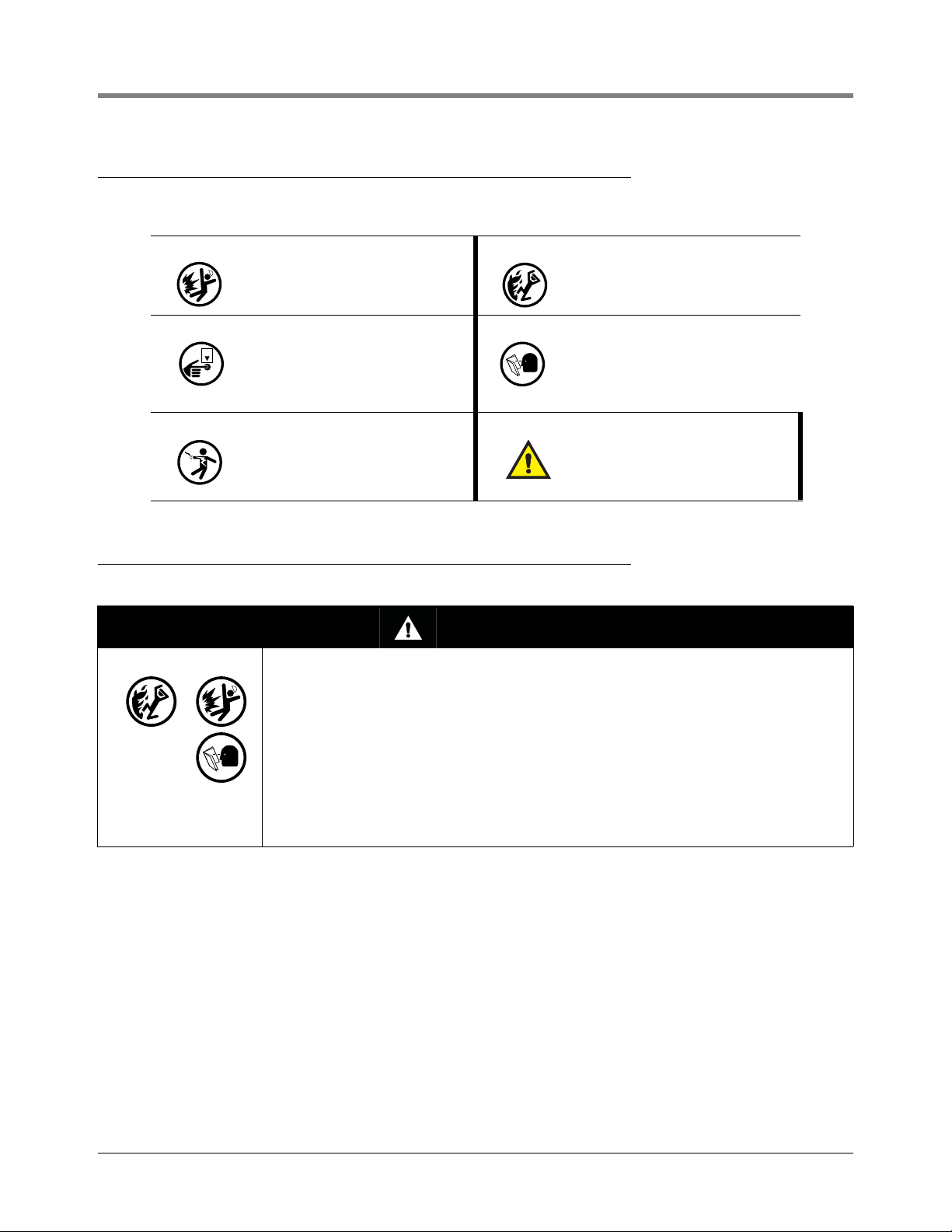
The following safety symbols may be used in this manual to alert you to important safety hazards and precautions.
Safety Warnings
EXPLOSIVE
Fuels and their vapors are extremely
explosive if ignited.
TURN POWER OFF
Live power to a device creates a
potential shock hazard. Turn Off power
to the device and associated accessories when servicing the unit.
ELECTRICITY
High voltage exists in, and is supplied
to, the device. A potential shock hazard
exists.
FLAMMABLE
Fuels and their vapors are extremely
flammable.
READ ALL RELATED MANUALS
Knowledge of all related procedures
before you begin work is important.
Read and understand all manuals thoroughly. If you do not understand a procedure, ask someone who does.
WAR NING
Heed the adjacent instructions to avoid
damage to equipment, property, environment or personal injury.
WARNING
This system operates near highly combustible fuel storage tanks.
FAILURE TO COMPLY WITH THE FOLLOWING WARNINGS AND SAFETY
PRECAUTIONS COULD CAUSE DAMAGE TO PROPERTY, ENVIRONMENT,
RESULTING IN SERIOUS INJURY OR DEATH.
Leaking tanks can create serious environmental and health hazards. Improper
programming and operation may also result in equipment self-test failures and
submersible pump shutdowns. It is the owner’s responsibility to:
1. Ensure that this equipment is properly programmed.
2. Promptly investigate any alarm conditions.
3. Operate this equipment in accordance with the instructions in this manual.
1-2
Page 15
2 Front Panel Keypads
consoles\keypad.eps
MODE
BACKUP
FUNCT-
TION
PRINT CHANGE STEP
PAPER
FEED
ENTER
QZ.
ABC
DEF
GHI JKL MNO
PRS TUV WXY
ALARM
TEST
TANK
SENSOR
,
+/-
0
789
123
456
1
4 3
2
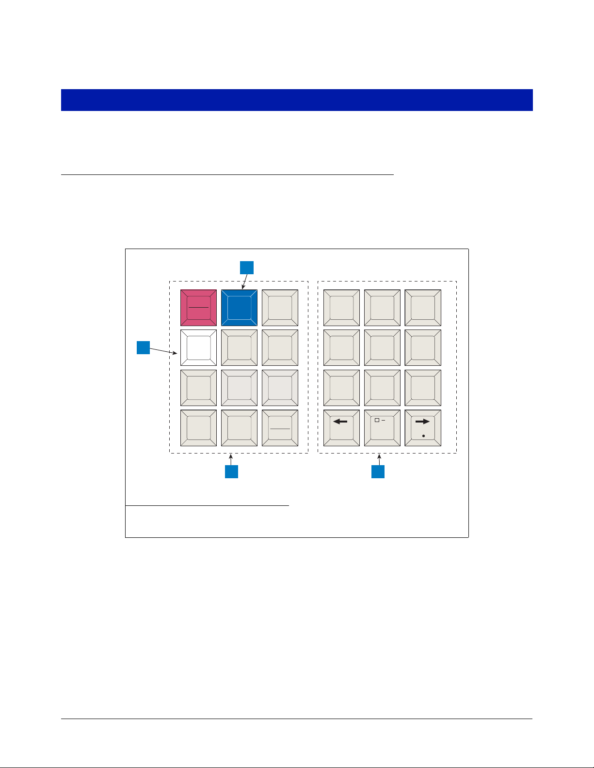
You use the front panel keypads to enter information into the system.
Arrangement of Keys
The keypads (see Figure 2-1) consist of two groups of 12 keys. The functions for each key have been established
to make movement within the setup mode, entry of setup data, and selection of setup choices as simple as
possible
.
Legend for numbered boxes:
1. Maintenance Report (white) key 3. Alphanumeric keypad
2. Maintenance Tracker (blue) key 4. Operating keypad
Figure 2-1. Console Keypads
OPERATING KEYS
The 12 left-hand keys are operating keys. They allow you to access and print data, start and stop in-tank leak test
procedures, program the system, test system operation and review diagnostic information. (See “Using the
Operating Keys” on page 2-2.)
ALPHANUMERIC KEYS
The 12 right-hand keys have alphanumeric and cursor movement functions for entering setup information.
2-1
Page 16

2 Front Panel Keypads Using the Operating Keys
MODE
FUNCTION
STEP
If a numeric value is required for entry of a particular setup parameter, the keys provide only numeric functions. If
either alphabetic or numeric characters may be entered, the keys provide both alphabetic and numeric functions.
(See “Using the Alphanumeric Keys” on page 2-3).
BLUE KEY (MAINTENANCE TRACKER - TLS-350 ONLY)
Contractor plugs a valid ID Key into the TLS and presses the blue key to log in for a work session. Note: This key
is available in consoles with Version 27 and higher software. In addition to certain hardware requirements, the
Maintenance Tracker feature must be enabled for this key to function.
WHITE KEY (MAINTENANCE REPORT - TLS-350 ONLY)
Press the white key to printout up to the last 75 maintenance history records. Additional records going back up to
3 years are also selectable. Note: This key is available in consoles with Version 27 and higher software and is
functional only if the Maintenance History or Maintenance Tracker feature enabled.
Using the Operating Keys
Operating key functions are summarized below.
ALARM
TEST
ALARM/TEST
Shuts off audible alarm and clears alarms that have returned to normal condition. Will not shut off
display indicators or disable alarm function. If your system has a printer, it will print an alarm or
warning report when this button is pressed.
Used to activate and de-activate output relays when OUTPUT RELAY TEST function is used.
MODE
Select operating modes: Normal Mode, Setup Mode, Diagnostic Mode.
If MODE is pressed while in a Function or Step, the system will advance to the next Mode.
FUNCTION
The FUNCTION key is used to scroll through and access functions within a Mode.
If FUNCTION is pressed while in a Step, the system will advance to the next Function.
STEP
Use the STEP key to move from one procedure to the next within a Function.
2-2
Page 17

2 Front Panel Keypads Using the Alphanumeric Keys
TANK
SENSOR
CHANGE
ENTER
BACKUP
PRINT
TAN K/ S EN S OR
The TANK/SENSOR key is used to advance by tank or sensor through setup procedures or displayed data.
CHANGE
CHANGE is used in Normal and Setup modes to enter data, revise existing data or change an
entry.
ENTER
ENTER completes a selection or enters data into a function. It is also used to start certain functions such as leak tests.
BACKUP
BACKUP lets you move back through Steps, Functions and Modes to access data or entries you
have already passed in the normal progression. It eliminates the need to move completely
through a function or mode to access a step recently passed.
BACKUP will move through the hierarchy of commands as follows: through Steps within a Function to that Function; then back through Functions to Mode; then back through Modes.
PRINT
Press PRINT to generate inventory, delivery, leak test, status, setup, diagnostic and alarm history
reports.
Using the Alphanumeric Keys
You use alphanumeric keys to enter data during the setup process. When a numeric value is required (i.e.gallons,
time, etc.), the keys provide only a numeric function. When you can enter either alphabetic or numeric characters
(i.e. station headers, sensor locations, etc.), the keys provide both functions.
2-3
Page 18
2 Front Panel Keypads Using the Alphanumeric Keys
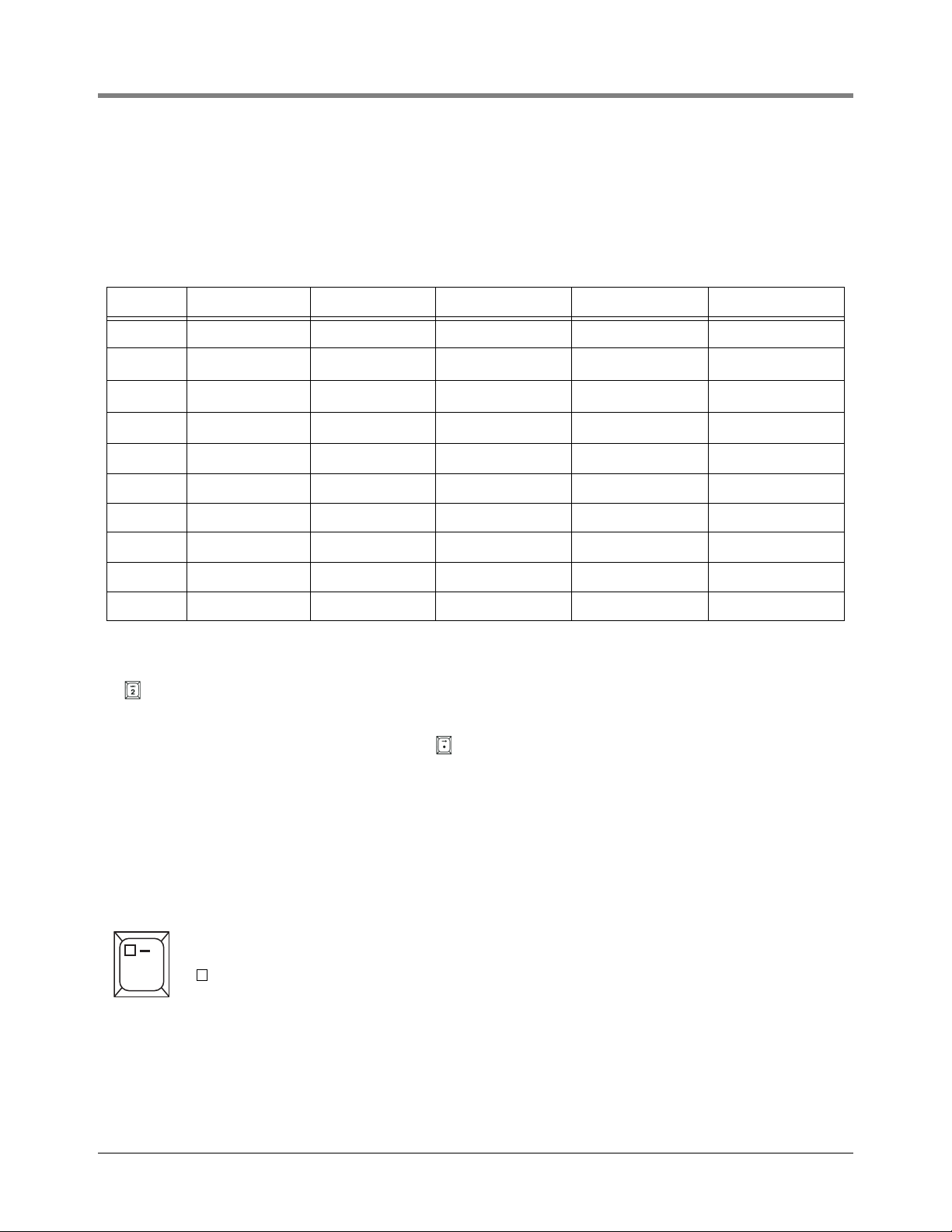
ENTERING ALPHANUMERIC DATA
Keys 0 through 9 provide both alphabetic and numeric capability by activating each character shown on the key
with successive pushes of the key. Table 2-1 shows characters assigned to each of the numeric keys for all
languages except Japanese, Russian, Turkish, and Greek.
Table 2-1. Character Assignments for Numeric Keys
Key 1st Key Press 2nd Key Press 3rd Key Press 4th Key Press 5th Key Press
Key 0 ‘space’ ‘-’ ‘,’ ‘0’ ‘*’
Key 1 ‘Q’ ‘Z’ ‘.’ ‘1’ ‘&’
Key 2 ‘A’ ‘B’ ‘C’ ‘2’ ‘=’
Key 3 ‘D’ ‘E’ ‘F’ ‘3’ ‘%’
Key 4 ‘G’ ‘H’ ‘I’ ‘4’
Key 5 ‘J’ ‘K’ ‘L’ ‘5’
Key 6 ‘M’ ‘N’ ‘O’ ‘6’
Key 7 ‘P’ ‘R’ ‘S’ ‘7’
Key 8 ‘T’ ‘U’ ‘V’ ‘8’
Key 9 ‘W’ ‘X’ ‘Y’ ‘9’
1
Character only available when entering the Modem Setup String.
1
1
1
For example, to enter an “A” in a station header, which accepts either alphabetic or numeric characters, you press
the key once. Push the key again to change the character to a “B”, again to enter a “C”, and again to enter a “2”.
The period (.) is on key “1”.
When the correct selection is displayed, press the key to move the cursor to the next position and enter the
required character as described. When all the characters have been entered, press ENTER.
If you enter an incorrect character, you may use the arrow keys to move the cursor to the character, press
CHANGE, and enter the correct character.
SPECIAL CHARACTERS AND CURSOR MOVEMENT
Several keys let you enter special characters and move the cursor as follows:
The Zero key has a comma (,) plus two special characters that can be used in making alphanumeric
entries. They are:
,
0
= Space (no character)
— = Dash
(a “*” character is generated by pressing this key 5 times).
2-4
Page 19

2 Front Panel Keypads Using the Alphanumeric Keys
+/-
The Right-Arrow key lets you advance the cursor to the right when making alphanumeric entries
such as station headers and when selecting certain parameters such as module configurations.
The step-by-step setup instructions will identify when this function should be used. The . (decimal)
is used in numeric entries as required. It is not used as a period for text entries.
The Left-Arrow key lets you move the cursor to the left.
The +/- is used to identify a positive or negative value.
2-5
Page 20

3 Setup Mode Organization
The Setup Mode is used to enter information and operating parameters that govern the way your system monitors
your installation. Setup data is entered via the front panel keypads. The previous section describes in detail the
functions of each key.
Functions
Functions are the major groups in the Setup Mode of the console.
IMPORTANT! The list below contains all of the available Setup Mode functions. However, only the functions
relevant to your console and its installed options and connected detection systems will be accessible in setup.
• System Setup
• Communications Setup
• In-Tank Setup
• Fuel Management Setup
• In-Tank Leak Test Setup
• Pressure Line Leak Setup
• WPLLD Line Leak Setup
• Line Leak Detector Setup [VLLD]
• Line Leak Test Setup
• Line Leak Lockout Setup
• Pump Sensor Setup
• Pump Relay Monitor Setup
• Reconciliation Setup
• Liquid Sensor Setup
• Vapor Sensor Setup
• Groundwater Sensor Setup
• 2-Wire C.L. Sensor Setup
• 3-Wire C.L. Sensor Setup
• External Input Setup
• Output Relay Setup
• PLLD Line Disable Setup
• WPLLD Line Disable Setup
• Line Disable Setup [VLLD]
• Smart Sensor Setup
• VMC Setup
• Archive Utility
Steps
Within each FUNCTION are STEPS at which you enter setup data.
Setup Mode Programming Table
The table below takes you through the complete setup mode as it appears in the console display with all features
installed (all choices may not appear on your TLS). Always press the ENTER key after entering data. If you press
the STEP, FUNCTION, or MODE key without pressing ENTER, the data will not be saved. It is a good idea to print
3-1
Page 21

3 Setup Mode Organization Setup Mode Programming Table
a setup report for record keeping purposes after completing your system’s setup. In the System Setup Table
below,
FUNCTION or STEP refers to pressing that key on the front panel.
Setup Mode Table
FUNCTION SYSTEM SETUP
STEP
STEP
STEP
STEP
STEP
STEP
STEP
STEP
STEP
STEP
STEP
STEP
STEP
STEP
STEP
STEP
STEP
STEP
STEP
STEP
STEP
STEP
STEP
STEP
STEP
STEP
STEP
STEP
STEP
STEP
STEP
STEP
STEP
STEP
STEP
STEP
STEP
STEP
STEP
STEP
STEP
System Language - English/ and second language as ordered
System Units (U.S./Metric/Imperial Gallons)
Date/Time Format
Set Month Day Year
Set Time
Station Header Line 1 (Line 2/Line 3/Line 4)
Shift #1 Start Time (Shift 2/Shift 3/Shift 4)
Shift BIR Printouts (Enable/Disable)
Daily BIR Printouts (Enable/Disable)
Ticketed Delivery (Enable/Disable)
TC Ticketed Delivery (Enable/Disable)
Close Day Of Week
Daily Dlvy Var Rpts (Disable/Enable)
Weekly Dlvy Var Rpts (Disable/Enable)
Periodic Dlvy Var Rpts (Disable/Enable)
Daily Book Dlvy Var Rpts (Disable/Enable)
Weekly Book Dlvy Var Rpts (Disable/Enable)
Periodic Book Dlvy Var Rpts (Disable/Enable)
Daily Var Analy Rpts (Disable/Enable)
Weekly Var Analy Rpts (Disable/Enable)
Periodic Var Analy Rpts (Disable/Enable)
Tank Per Tst Needed Wrn (Disable/Enable)
Tank Per Tst Needed Wrn Days
Tank Per Tst Needed Alm Days
Tank Ann Tst Needed Wrn Days
Tank Ann Tst Needed Alm Days
Line Reenable Method (Pass Line Test/Alarm Acknowledge)
Line Per Tst Needed Wrn (Disable/Enable)
Line Per Tst Needed Wrn Days
Line Per Tst Needed Alm Days
Line Ann Tst Needed Wrn (Disable/Enable)
Line Ann Tst Needed Wrn Days
Line Ann TsT Needed ALM Days
Remote Printer Page Eject
Print Tc Volume
Temp Compensation
Tanker Load Report
Stick Height Offset (Disable/Enable)
Ullage (90%/95%)
H-Protocol Data Format
Precision Test Duration (12 - 744 hrs [w/o CSLD]/60 - 744 hrs [w/CSLD])
3-2
Page 22

3 Setup Mode Organization Setup Mode Programming Table
FUNCTION
STEP
STEP
STEP
STEP
STEP
STEP
STEP
STEP
STEP
STEP
STEP
STEP
STEP
STEP
STEP
STEP
STEP
0.2 gph (0.76 lph) Line Test Auto-Confirm (Enable/Disable)
0.1 gph (0.38 lph) Line Test Auto-Confirm (Enable/Disable)
Daylight Savings Time (Disable/Enable)
HRM-QPLD Printouts (Enable/Disable)
Re-direct Local PrintouT (Enable/Disable)
Euro Protocol Prefix
Bdim Trans Alarm Delay
System Security Code
Maintenance History (Enable/Disable)
Tank C h a rt Se c u rity
Custom Alarms
Service Notice
Inventory Alarms Threshold Units (Standard, All % Full, All Volume, All Height, Custom)
System Beeper (Enable/Disable)
Mass/Density
Fiscal Height Security
Alarm Reduction (Enable/Disable)
COMMUNICATION SETUP
STEP
Comm Board Port Settings - Repeat for each board (Baud Rate/Parity/Stop Bit/Data Length/
Dial Type/Answer On/Code/Modem Setup String/Dial Tone Interval/DTR Normal State
STEP
Auto Transmit Setup (Transmit Message Setup/Auto-Transmit Delay Time/Auto-Transmit Repeat
Time)
STEP
STEP
STEP
STEP
Phone Directory Setup
Auto Dial Setup
Auto Dial Alarm
RS-232 End Of Message
FUNCTION
IN-TANK SETUP
STEP
STEP
STEP
STEP
STEP
STEP
STEP
STEP
STEP
STEP
STEP
STEP
STEP
STEP
STEP
STEP
STEP
STEP
STEP
Tank Config Module 1 (Up To 3)
Product Label
Product Code
Thermal Coeff.
Tank Density
Tank Diameter
Tank Profile (1 Pt/4 Pts/20 Pts/linear/50 Pts)
Full Volume
Meter Data Present
Vapor Loss Factor
End Factor (None/Flat/Hemispherical/Other)
End Value
Calibration Update
Float Size
Water Mini mum
Water Warning Limit (Not Active For Tanks With High Alcohol Probes)
High Water Limit (Not Active For Tanks With High Alcohol Probes)
Water Alarm Filter (Not Active For Tanks With High Alcohol Probes)
Max Or Label Volume
3-3
Page 23

3 Setup Mode Organization Setup Mode Programming Table
STEP
STEP
STEP
STEP
STEP
STEP
STEP
STEP
STEP
STEP
STEP
STEP
STEP
STEP
STEP
STEP
STEP
STEP
STEP
STEP
STEP
STEP
STEP
Overfill Limit
High Product
Delivery Limit
Low Product
Leak Alarm Unit
Sudden Loss Limit
Tank Ti l t
Probe Offset
Siphon Manifolded
Line Manifolded
Leak Minimum Periodic
Leak Minimum Annual
Periodic Test Type
Annual Test Fail Alarm
Periodic Test Fail Alarm
Gross Test Fail Alarm
Annual Test Averaging
Periodic Test Averaging
Tank Te s t N oti f y
Tank Te s t S iph o n B rea k
Stick Offset
Delivery Delay
Pump Threshold
FUNCTION
FUNCTION
FUNCTION
FUEL MANAGEMENT SETUP
STEP
STEP
STEP
Delivery Warn Days XX.X
Fuel Management Auto Print
Average Daily Sales
IN-TANK LEAK TEST SETUP
STEP
STEP
Test M e t hod ( S i ngl e Ta n k/A ll Ta n k s )
Test Frequency (On Date/Annually [Month/Week, Day]/Monthly [Week, Day]/Weekly [Day]/
Daily/ Auto [If line leak or pump sense]/CSLD - if enabled [Prob. Detect.(9%/99%)]/Climate
Factor [Moderate/Extreme])
STEP
STEP
STEP
STEP
STEP
STEP
Gross Test Auto-Confirm (If CSLD select with Pump Sense)
Test Start Time
Leak Test Rate (0.2gph [0.76 lph]/0.1 gph [0.38 lph])
Test D u r atio n
Leak Test Early Stop
Report Only - if CSLD selected (Disabled/End of Month/Day 15 and End of Month/Day 25 and
End of Month)
STEP
Leak Test Report Format (Normal/Enhanced)
PRESSURE LINE LEAK SETUP
STEP
STEP
STEP
STEP
Line Config. - Module 1 ( up to 3)
Pressure Line Label
Piping Type
Line Length
3-4
Page 24

3 Setup Mode Organization Setup Mode Programming Table
FUNCTION
STEP
User Defined Pipe Type - If selected in Piping Type (1st Line Length/2nd Line Length - if necessary/1st Bulk Modulus/2nd Bulk Modulus- if necessary/Thermal Coeff.)
STEP
STEP
STEP
STEP
Thermal Coefficient - If certain piping types selected
0.2 gph (0.76 lph) Line Leak Test Scheduling (Disabled/Repetitive/Monthly/Manual)
0.1 gph (0.38 lph) Line Leak Test SchedulingTest (Disabled/Repetitive/Auto/Manual)
Passive 0.1 gph (0.38 lph) Line Leak Testing (if certain pipe type selections made and 0.1 gph
line leak test shedule selection is auto)
STEP
STEP
STEP
STEP
STEP
STEP
STEP
STEP
Shutdown Rate (3.0 gph [11.3 lph]/0.2 gph [0.76lph]/0.1 gph [0.38 lph]/None)
Low Pressure Alarm Shutoff (No/Select Value)
Select Tank - in which PLLD controlled pump is installed (None/Select Number)
Dispense Mode
Pressure Transducer (Non-Vented/Vented/High Pressure)
Pressure Offset Value
Mechanical Blender
Blend Partners
WPLLD LINE LEAK SETUP
STEP
STEP
STEP
STEP
STEP
STEP
STEP
STEP
STEP
Line Config. Module 1 ( up to 3)
WPLLD Line Label
Piping Type
Line Length
0.2 gph (0.76 lph) Test (Disabled/Repetitive/Monthly/Manual)
0.1 gph (0.38 lph) Test (Disabled/Auto/Manual)
Shutdown Rate (3.0 gph [11.3 lph]/0.2 gph [0.76lph]/0.1 gph [0.38 lph]/None)
Dispense Mode
Pressure Offset Value
FUNCTION
FUNCTION
LINE LEAK DETECTOR SETUP (Volumetric)
STEP
STEP
STEP
STEP
STEP
STEP
STEP
STEP
STEP
STEP
STEP
STEP
STEP
Line Config. Module 1 ( up to 8)
Enter Pipe Label
Tank #
Dispense Mode (Standard/Manifold:Alternate/Manifold:Sequential/Manifold:All Pumps)
Fuel Type (Gasoline/Diesel)
2-inch (50mm) Piping Length
3-inch (76mm) Piping Length
Pipe Type (Steel/Fiberglass/2-wall Fiberglass/Flexible)
Pump Pressure
Shutdown Rate (3.0 gph [11.3 lph]/0.2 gph [0.76lph]/0.1 gph [0.38 lph])
Pumpside Test
Wait Mode (Temp. Meas./Vol. Chg. Meas.)
NPB Partner
LINE LEAK TEST SETUP
STEP
STEP
Leak Test Method (All Lines/Single Line)
Test Frequency (On Date/Annually [Month/ Week, Day]/Monthly [Week, Day]/ Weekly [Day]/
Daily)
STEP
STEP
Leak Test Start Time
Test Rate (0.2 gph [0.76 lph]/0.1 gph [0.38 lph])
3-5
Page 25

3 Setup Mode Organization Setup Mode Programming Table
FUNCTION
FUNCTION
FUNCTION
FUNCTION
LINE LEAK LOCKOUT SETUP
STEP
Lockout Schedule (Daily [Start Time/Stop Time]/ Individual [Start Day/Time/Stop Day/Time])
PUMP SENSOR SETUP
STEP
STEP
STEP
Pump Sense Config. Module 1 ( up to 8)
Select Tank
Dispense Mode
PUMP RELAY MONITOR SETU P
STEP
STEP
STEP
Pump Relay Config. Module 1 ( up to 8)
Enter Pump Monitor Label
Select Pump Relay (None/PumpSense/PLLD/WPLLD/VLLD/Relay [Pump Control Output
only])
STEP
STEP
Stuck Delay - 5 - 600 sec (Visible only if Relay assigned)
Select Max Run Time - 1 - 24 hr (Visible If None was selected for Pump Relay)
RECONCILIATION SETUP
STEP
STEP
STEP
STEP
STEP
STEP
STEP
STEP
STEP
STEP
STEP
STEP
STEP
STEP
Dispenser Module Data String
Automatic Daily Closing Time
Auto Shift #1 Closing Time
Auto Shift #2 Closing Time
Auto Shift #3 Closing Time
Auto Shift #4 Closing Time
Periodic Reconciliation Mode (Monthly/Rolling [Length])
Periodic Reconciliation Alarm (Disabled/Enabled)
Periodic Reconciliation Alarm Threshold
Periodic Reconciliation Offset
Remote Report Format (Line/Column)
Temp Compensation (Standard/TC Vol)
Meter Calibration Offset
Modify Tank/Meter Map
FUNCTION
FUNCTION
FUNCTION
LIQUID SENSOR SETUP
STEP
STEP
STEP
Sensor Config. - Module 1 (up to 8)
Sensor Location
Sensor Types (Tri-State/NC/Dual Float Hydrostatic/Dual Float Discriminating/Dual Float High
Vapor/Interceptor)
STEP
Category (Annular Space/Dispenser Pan/Monitor Well/STP Sump/Piping Sump/Other)
VAPOR SENSOR SETUP
STEP
STEP
STEP
STEP
Sensor Config. - Module 1 (up to 8)
Sensor Location
Sensor Threshold
Category (Annular Space/Dispenser Pan/Monitor Well/STP Sump/Piping Sump/Other)
GROUNDWATER SENSOR SETUP
STEP
Sensor Config. - Module 1 (up to 8)
3-6
Page 26

3 Setup Mode Organization Setup Mode Programming Table
FUNCTION
FUNCTION
FUNCTION
STEP
STEP
Sensor Location
Category (Annular Space/Dispenser Pan/Monitor Well/STP Sump/Piping Sump/Other)
2-WIRE CL SENSOR SETUP
STEP
STEP
STEP
STEP
Sensor Config. - Module 1 (up to 8)
Sensor Location
Sensor Types (Discrim. Interstitial/Ultra 2)
Category (Annular Space/Dispenser Pan/Monitor Well/STP Sump/Piping Sump/Other)
3-WIRE CL SENSOR SETUP
STEP
STEP
STEP
STEP
Sensor Config. - Module 1 (up to 8)
Sensor Location
Sensor Mode (Standard/High Vapor)
Category (Annular Space/Dispenser Pan/Monitor Well/STP Sump/Piping Sump/Other)
EXTERNAL INPUT SETUP
STEP
STEP
STEP
Input Config. - Module 1 (up to 8)
Input Name
External Input Type (Standard [NO/NC]/Generator [Select Orientation (NO/NC)/Generator
Tank [All Tanks/By Tank]/Pump Sense [Select Orientation (NO/NC)/Select Tank (Tank #/
None)/Dispense Mode)
STEP
Standard ACK (NO/NC)
FUNCTION
FUNCTION
FUNCTION
OUTPUT RELAY SETUP
STEP
STEP
STEP
Relay Config. - Module 1 (up to 8)
Enter Relay Designation
Select Relay Type (Standard [NO/NC]/Pump Control Output [Select Tank (None/Tank #)]/
Momentary [NO/NC]/Pump Comm Control [Select Tank (None/Tank #)])
STEP
Relay Assignments - for each relay except Pump Comm Control types (In-Tank Alarms [None/
All /Single]/ Liquid Sensor Alarms [None/All /Single]/ Vapor Sensor Alarms [None/All /Single]]/
External Inputs [None/All /Single]]/ Line Leak Alarms - VLLD [None/All /Single]/ Groundwater
Alarms [None/All /Single]/ 2-Wire CL (Type A) Alarms [None/All /Single]/ 3-Wire CL (Type B)
Alarms [None/All /Single]/ Power Side DIM Alarms [None/All /Single]/ Reconciliation Alarms
[None/All /Single]/ PLLD Alarms [None/All /Single]/ WPLLD Alarms [None/All /Single]/ Comm
Side DIM Alarms [None/All /Single]/ Pump Relay Monitor Alarms [None/All /Single]
PLLD LINE DISABLE SETUP
STEP
Relay Assignments - for each relay except Pump Comm Control types (In-Tank Alarms [None/
All /Single]/ Liquid Sensor Alarms [None/All /Single]/ Vapor Sensor Alarms [None/All /Single]]/
External Inputs [None/All /Single]]/ Line Leak Alarms - VLLD [None/All /Single]/ Groundwater
Alarms [None/All /Single]/ 2-Wire CL (Type A) Alarms [None/All /Single]/ 3-Wire CL (Type B)
Alarms [None/All /Single]/ Power Side DIM Alarms [None/All /Single]/ Reconciliation Alarms
[None/All /Single]/ PLLD Alarms [None/All /Single]/ WPLLD Alarms [None/All /Single]/ Comm
Side DIM Alarms [None/All /Single]/ Pump Relay Monitor Alarms [None/All /Single]
WPLLD LINE DISABLE SETUP
STEP
Relay Assignments - for each relay except Pump Comm Control types (In-Tank Alarms [None/
All /Single]/ Liquid Sensor Alarms [None/All /Single]/ Vapor Sensor Alarms [None/All /Single]]/
External Inputs [None/All /Single]]/ Line Leak Alarms - VLLD [None/All /Single]/ Groundwater
Alarms [None/All /Single]/ 2-Wire CL (Type A) Alarms [None/All /Single]/ 3-Wire CL (Type B)
Alarms [None/All /Single]/ Power Side DIM Alarms [None/All /Single]/ Reconciliation Alarms
[None/All /Single]/ PLLD Alarms [None/All /Single]/ WPLLD Alarms [None/All /Single]/ Comm
Side DIM Alarms [None/All /Single]/ Pump Relay Monitor Alarms [None/All /Single]
3-7
Page 27

3 Setup Mode Organization Setup Mode Programming Table
FUNCTION
FUNCTION
FUNCTION
FUNCTION
LINE DISABLE SETUP (VLLD)
STEP
Relay Assignments - for each relay except Pump Comm Control types (In-Tank Alarms [None/
All /Single]/ Liquid Sensor Alarms [None/All /Single]/ Vapor Sensor Alarms [None/All /Single]]/
External Inputs [None/All /Single]]/ Groundwater Alarms [None/All /Single]/ 2-Wire CL (Type
A) Alarms [None/All /Single]/ 3-Wire CL (Type B) Alarms [None/All /Single]/ Power Side DIM
Alarms [None/All /Single]/ Reconciliation Alarms [None/All /Single]/ PLLD Alarms [None/All /
Single]/ WPLLD Alarms [None/All /Single]/ Comm Side DIM Alarms [None/All /Single]/ Pump
Relay Monitor Alarms [None/All /Single]
SMART SENSOR SETUP
STEP
STEP
STEP
SS Config. - Module 1 (up to 8)
Enter SmartSensor Label
Select SS Category (Air Flow Meter[ISD System Device - ref. manual 577013-800]/ Vapor
Pressure [ISD System Device - ref. manual 577013-800]/ Mag Sensor/ Vac Sensor/ ATMP
Sensor/ Uknown)
VMC SETUP
STEP
Add/Edit/Remove VMC Serial Number
ARCHIVE UTILITY
STEP
STEP
STEP
Save Setup Data
Restore Setup Data
Clear Setup Data
3-8
Page 28

4 Prior to Applying AC Power to the Console
Please read this section before applying AC power to the console.
Security Code Enable/Disable
Access to all setup functions through either the front panel and/or the RS-232 interface can be restricted by the
use of security codes. Once this feature has been activated, only persons knowing the user-designated codes may
enter or change any setup values.
This feature will prevent unauthorized persons from intentionally or accidentally entering or changing setup values.
Two separate Security Codes may be entered—one to restrict access to the Setup Mode from the front-panel
keyboard and another to restrict remote access through the RS-232 interface.
Open the left front panel door and locate the slide switch for the battery and the DIP switch. See appropriate
figure for your console (Figure 4-1 - Figure 4-3).
TLS-300 CONSOLES
IMPORTANT! DIP switch #2 controls the power to the front-panel display and must be in the OPEN position!
If you want to enable the security code feature and require entering of the security code(s) for front-panel and/or
RS-232 system setup access, make sure that switches #3 and/or #4 on DIP switch S2 are in the Closed position.
If you want to disable the security code feature and allow front panel and RS-232 system setup access, make sure
that switches #3 and #4 on DIP switch S2 are both in the OPEN position.
TLS-350 CONSOLES
If you want to disable the security code feature and allow front panel and RS-232 system setup access, make sure
that switches #1 and #2 on DIP switch SW2 are both in the OPEN position.
If you want to enable the security code feature and require entering of the security code(s) for front-panel and/or
RS-232 system setup access, make sure that switches #1 and/or #2 on DIP switch SW2 are in the Closed
position.
IMPORTANT! DIP switch #3 controls the power to the front-panel display and must be in the OPEN position!
When switch #3 is closed, the console display remains blank. For international operation only! - set DIP switch 3
to the Closed position to enable HRM.
DIP switch #4 is not used at this time and may be in either position. DIP switch #1 is not used at this time and
may be in either position.
4-1
Page 29
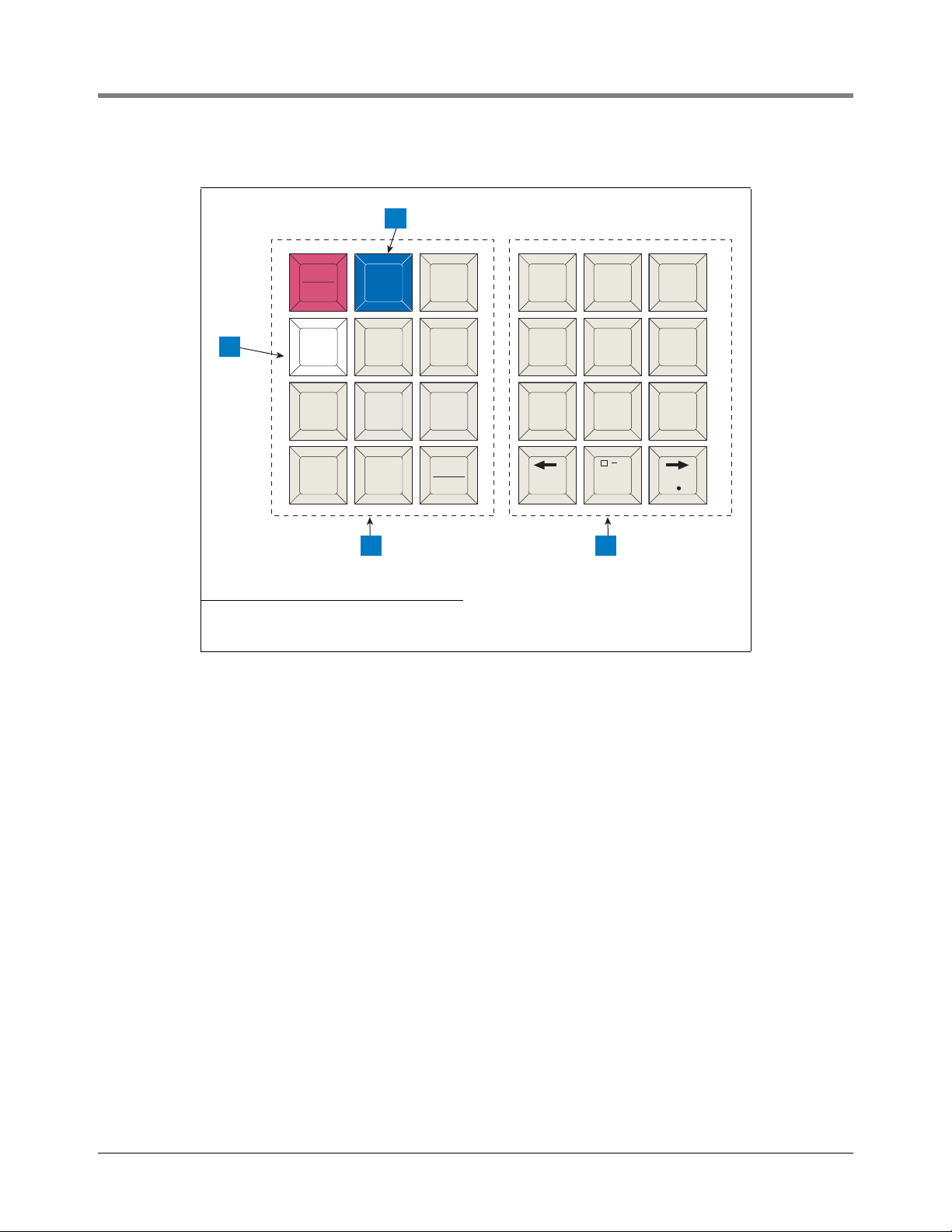
4 Prior to Applying AC Power to the Console Security Code Enable/Disable
consoles\keypad.eps
MODE
BACKUP
FUNCT-
TION
PRINT CHANGE STEP
PAPER
FEED
ENTER
QZ.
ABC
DEF
GHI JKL MNO
PRS TUV WXY
ALARM
TEST
TANK
SENSOR
,
+/-
0
789
123
456
1
4 3
2
Legend for numbered boxes:
1. Maintenance Report (white) key 3. Alphanumeric keypad
2. Maintenance Tracker (blue) key 4. Operating keypad
4-2
Page 30
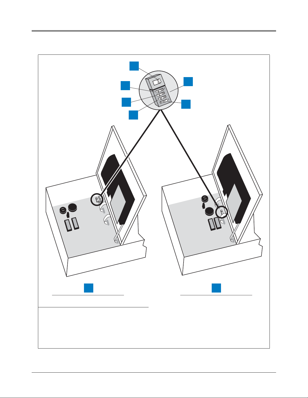
4 Prior to Applying AC Power to the Console Security Code Enable/Disable
1
1
2
3
S1
OPEN
1234
S2
6
5
4
consoles\300dp1.eps
8 7
Legend for numbered boxes:
1. Battery Backup Switch (S1) shown in OFF position 5. DIP switch 1 can be in either position - It is shown in closed
2. Front Panel Security Code (DIP Switch 4) 6. Switch (S2)
3. RS-232 Security Code (DIP Switch 3) 7. S1 and S2 Locations in Consoles with Through-Hole Mount
4. Front Panel Display (DIP Switch 2) 8. S1 and S2 Locations in Consoles with Surface Mount CPU
Figure 4-1. Battery Backup Switch and DIP Switch Location - TLS-300 Console
position (open side up, number side down)
CPU Board
Board
4-3
Page 31

4 Prior to Applying AC Power to the Console Security Code Enable/Disable
consoles\cpubbsw1.eps
BATT
1234
S1
S2
OPEN
OPEN
1
2
3
7
6
5
4
Legend for numbered boxes:
1. CPU Board 5. DIP Switch 4 (not used)
2. Front Panel Security Code (DIP Switch 1) 6. Front Panel Display (DIP Switch 3)
3. Battery Backup Switch (S1) - Shown in ON position
(up)
4. DIP switches: 1 - 4 shown in the OPEN position
(open end down, number end up)
7. RS-232 Security Code (DIP Switch 2)
Figure 4-2. Battery Backup Switch and DIP Switch Location TLS-350 Consoles with CPU Board
4-4
Page 32

4 Prior to Applying AC Power to the Console Security Code Enable/Disable
SW2
SW1
consoles\ecp350sw1.eps
1234
OPEN
1
2
3
4
5
6
7
Legend for numbered boxes:
1. ECPU board 5. DIP switches: 1 - 4 shown in the OPEN position (open end
2. View Front Panel Display (DIP Switch 3) 6. Battery Backup Switch (SW1)- Shown in OFF position
3. RS-232 Security Code (DIP Switch 2) 7. DIP Switch 4 (not used)
4. Front Panel Security Code (DIP Switch 1)
down)
(down)
Figure 4-3. Battery Backup Switch and DIP Switch Location TLS-350 Consoles with ECPU Board
4-5
Page 33

4 Prior to Applying AC Power to the Console Battery Backup
CLEARING ALL RAM
SYSTEM COLD START
SYSTEM SELF TEST
WORKING
********************
SYSTEM STARTUP COMPLETE
MMM DD, YYYY HH:MM:SS XM
RESTORE SETUP DATA?
Battery Backup
The system is equipped with an internal backup battery to protect all setup and operating data in the event of an
AC-power interruption.
The system is shipped from the factory with the Battery Backup slide switch in the OFF position. Make sure this
switch is in the OFF position before applying AC power to the console.
Applying AC Power to the Console
1. Open the left front door of the console. With the Battery Backup switch in the OFF position, turn On AC power
to the console.
2. The console front panel display will cycle through the following screens: (NOTE: if you enabled the HRM
feature (see “TLS-350 Consoles” on page 4-1), the system date/time format will default to DD-MM-YY
HH:MM:SS).
The display below appears only if you have one of the modem modules or WPLLD installed:
The message below appears in consoles with Archive Utility feature only. For more information about saving and
restoring system setup data, refer to “Archive Utility” on page 28-1.
At this point the ALARM audible beeper and front panel light will begin turning on and off, and the printer will
printout:
**** SYSTEM RESET ****
MMM DD, YYYY HH:MM XM
4-6
Page 34

4 Prior to Applying AC Power to the Console Applying AC Power to the Console
MMM DD, YYYY HH:MM:SS XM
BATTERY IS OFF
MMM DD, YYYY HH:MM:SS XM
ALL FUNCTIONS NORMAL
and the front panel display will read:
3. Press the ALARM/TEST key to silence the audible alarm. Slide the Battery Backup switch (S1 or SW1) to the
ON position. After a few seconds, the alarm light will go out and the front panel display will read:
4. You can now begin the System Setup procedure.
4-7
Page 35

5 System Setup
Programming Guidelines
This manual details setup procedures for every available console Function within the Setup Mode. The manual is
divided into sections for each Function as they appear on the display, beginning with Section 5, System Setup
through Section 26, Archive Utility. Depending on your console type and its installed features, you may only see
(and be able to program) some of the Functions and/or Steps. Just skip over the material in this manual that
doesn’t apply to your installation. The screen examples shown in this manual, are in U.S. units. However, Metric or
Imperial units would appear if either of those choices were selected in the System Units step.
• Programming Instructions. All the programming instructions in this manual assume that this is a first-time
(cold-start) setup.
• Sample Screens. The screens that are shown in these setup procedures display factory-set values or choices.
If you change these settings as you set up the system for your application, your setup values or choices will
appear in the display when the Setup Mode is re-entered.
• Key Functions. The keys used to revise any setting are the same as used during initial programming, although
the key sequences may change.
• Multiple Choice Entries. The setup procedure mentioned in this manual instructs you to press the STEP key
to accept a default value and move to the next setup parameter. When you are offered multiple choices, press
the CHANGE key to display these alternate choices, and the ENTER key to confirm the choice you decide
upon.
Automatic Return to Operating Mode
The system will automatically return to the Operating Mode status display in 15 minutes if no activity takes place
while the system is in the Setup Mode. Mark where you are in the setup sequence if you are going to be away for
longer than this.
Setup Data Warning
When you exit the Setup Mode, a Setup Data Warning will appear in the Status Display and the yellow warning
light will flash if insufficient or invalid setup data has been entered. In systems equipped with a printer, a Setup
Data Warning report will also be printed.
The display and report will identify the source of the warning (i.e. Tank 1, Sensor 4, etc.), and the warning
indicators will remain active until the cause has been corrected.
Printing a Setup Data Report
You should print and save a setup data report once all setup procedures are complete. This report will be a record
of all setup values entered into this system and save valuable time if system memory is lost due to a simultaneous
interruption of AC and battery power, or due to a problem within the system.
5-1
Page 36

5 System Setup Selecting the System Setup Function
SETUP MODE
PRESS <FUNCTION> TO CONT
SYSTEM SETUP
PRESS <STEP> TO CONTINUE
SYSTEM LANGUAGE
ENGLISH
[Selected Language]
PRESS <STEP> TO CONTINUE
SYSTEM UNITS
U.S.
To print a Setup Data Report, press the MODE key to display the Setup Mode main screen (see below), then
press the PRINT key.
Selecting the System Setup Function
Press MODE to select the Setup Mode, then press FUNCTION until you see the message:
Press STEP to continue.
System Language
If necessary, press STEP until you see the message:
Once you choose a language, the system displays and prints all information in that language. Available language
choices depend on the language set specified when the system was ordered. The available language sets are:
• English/Dutch • English/French • English/Finnish
• English/German • English/Greek • English/Italian
• English/Japanese • English/Polish • English/Portuguese
• English/Russian • English/Spanish • English/Swedish
• English/Turkish
To choose English, press STEP. (The system displays the SYSTEM UNITS message.) NOTE: When using the
English/Japanese language set with a remote printer, you must set the printer’s data bit-per-character switch to 8
bits.
To choose an alternate language, press CHANGE, in response to the SYSTEM LANGUAGE message, and press
ENTER. The system displays the message:
Press STEP to continue.
System Units
If necessary, press STEP until you see the message:
5-2
Page 37

5 System Setup Setting the Date and Time Format
[Selected Units]
PRESS <STEP> TO CONTINUE
SYSTEM DATE/TIME FORMAT
MON DD, YYYY HH:MM:SS xM
SET: MONTH DAY YEAR
DATE: XX/XX/XXXX
DATE: XX/XX/XXXX
PRESS <STEP> TO CONTINUE
You can set the system units to U.S. units (gallons, gal/hour, inches, F), metric units (litres, litres/hour, millimeters,
C), or imperial gallons (imperial gallons, imp. gal/hour, inches, F). If the HRM feature was enabled (see “TLS-350
Consoles” on page 4-1), the default units will be metric.
NOTE: If you change the System Units after entering other quantitative setup values, the system converts values to
the new units. The Date format also changes according to your selection of System Units.
To choose U.S. units, press STEP. (The system displays the SET DATE message.)
To choose metric, press CHANGE in response to the SYSTEM UNITS message and press ENTER. To choose
imperial gallons, press CHANGE twice in response to the SYSTEM UNITS message and press ENTER. The
system confirms your choice with the message:
Press STEP to continue.
Setting the Date and Time Format
If necessary, press STEP until you see the message:
To accept the format shown, press STEP. (The system displays the SET TIME message).
Available date/time formats are:
• MON DD YYYY HH:MM:SS (APR 01 2002 10:02:30)
• MM-DD-YY HH:MM:SS xM (04-01-02 10:02:30 AM); xM is AM or PM
• MM-DD-YY HH:MM:SS (04-01-02 10:02:30)
• DD-MM-YY HH:MM:SS (01-04-027 10:02:30)
• YY-MM-DD HH:MM:SS (02-04-01 10:02:30)
Press CHANGE until the desired format is shown, then press ENTER. Press STEP to continue.
Current Date
If necessary, press STEP until you see the message:
To accept the date shown, press STEP. (The system displays the SET TIME message).
To change the date shown, press CHANGE, enter the correct date by first entering the month then the day then
the year following the format shown on the display, then press ENTER. The system confirms your entry with the
message:
Press STEP to continue.
5-3
Page 38

5 System Setup Current Time
SET TIME
TIME: XX:XX AM PM
TIME: XX:XX XM
PRESS <STEP> TO CONTINUE
ENTER STATION HEADER
#1:
#1: [1st Line Of Header]
PRESS <STEP> TO CONTINUE
SHIFT #1 START TIME
TIME: DISABLED
Current Time
If necessary, press STEP until you see the message:
To accept the time shown, press STEP. (The system displays the ENTER STATION HEADER message.)
To set a different time, press CHANGE and enter the correct time from 12:00 to 11:59 then am or pm. (Press the
Left or Right Arrow to select AM or PM). Press ENTER. The system confirms your entry with the message:
Press STEP to continue.
Report Headers
If necessary, press STEP until you see the message:
NOTE: The header can be up to four lines with 20 characters per line. Use the header to identify site location,
telephone number, etc. (See “Using the Alphanumeric Keys” on page 2-3 for instructions on how to enter
alphanumeric data.)
If you do not want a header for reports, press STEP. The system displays the SHIFT START TIME message.)
To create a header, press CHANGE in response to the ENTER STATION HEADER message. Enter up to 20
characters for the first line. Press ENTER. The system confirms your entry with the message:
To enter additional header lines, press STEP and repeat the above procedure up to three more times for lines 2, 3,
and 4. When you finish entering the header, press STEP to continue.
Shift Start Times
If necessary, press STEP until you see the message:
Setting shift start times can ease shift changes and improve fuel inventory management. At each programmed
time, the system automatically prints a complete inventory report and stores it in memory.
NOTE: At least one Shift Start Time must be entered to activate the “Last Shift Inventory” feature. If you have fewer
than three shifts and wish to receive a day-end inventory report at the end of the final shift, use the next shift start
time as the day-end time. The system automatically prints a final inventory.
5-4
Page 39

5 System Setup Shift BIR Printouts
TIME: XX:XX:XM
PRESS <STEP> TO CONTINUE
SHIFT #2 START TIME
TIME: DISABLED
SHIFT BIR PRINTOUTS
ENABLED
DAILY BIR PRINTOUTS
ENABLED
TICKETED DELIVERY
DISABLED
To leave a shift start time disabled, press STEP. (The system displays the SHIFT START TIME message for the
next shift.)
To set a start time for shift 1, press CHANGE, and enter the shift 1 start time. Press the Left or Right Arrow to
select AM or PM. Then press ENTER. The system confirms your entry with the message:
Press STEP. The system displays the SHIFT START TIME message for the next shift:
Repeat the above procedures to enter or disable start times for shifts 2, 3, and 4.
Shift BIR Printouts
If necessary, press STEP until you see the message:
Shift BIR Printouts enabled causes a BIR report to print at the end of every shift. If you want a BIR printout at the
conclusion of each shift, press STEP to continue. To disable Shift BIR Printouts, press CHANGE, ENTER, then
STEP.
Daily BIR Printouts
If necessary, press STEP until you see the message:
Daily BIR Printouts enabled causes a BIR report to print at the end of the day’s last shift. If you want a BIR
printout at the conclusion of the last shift, press STEP to continue. To disable Daily BIR Printouts, press
CHANGE, ENTER, then STEP.
Ticketed Delivery
If necessary, press STEP until you see the message:
When you enable ticketed delivery, you can manually enter ticketed volumes using the receipts from tank delivery
trucks. To enter this data, use the Delivery Maintenance function in the Operating Mode. This feature generates
reports showing delivery variances between ticketed volume and gauged volume, book variance, and variance
analysis. To enable Ticketed Delivery, press CHANGE, ENTER, then STEP.
5-5
Page 40

5 System Setup TC Ticketed Delivery
TC TICKETED DELIVERY
DISABLED
CLOSE DAY OF WEEK
SUN
DAILY DLVY VAR RPTS
DISABLED
WEEKLY DLVY VAR RPTS
DISABLED
TC Ticketed Delivery
If necessary, press STEP until you see the message:
If you enabled ticketed delivery, you can choose whether the values you enter are standard (gross) volumes or
temperature-compensated (TC) volumes (see page 5-13 for a description of “Temperature Compensation Value”).
For standard volumes, press STEP to leave TC Ticketed Delivery disabled. For TC volumes, press CHANGE,
ENTER, then STEP.
Close Day of Week
If necessary, press STEP until you see the message:
If you enabled ticketed delivery, you can choose the last day of the weekly cycle for Variance Reports. (Close Day
of Week is similar to “Automatic Daily Closing” on page 17-1.) Press CHANGE until the appropriate day appears,
then press ENTER and STEP.
Variance Reports
If you enabled ticketed delivery, you can print several different types of variance reports on demand from the
Reconciliation Mode (Operating Mode). Variance reports are similar to the reconciliation reports generated for BIR,
except they also show ticketed (book) delivery volume. Delivery Variance Reports show the difference between
ticketed delivery and gauged delivery volumes. Book Variance Reports show the difference between book
inventory and closing gauged volume. Variance Analysis Reports have the most detail because they summarize the
Delivery and Book Variance Reports and show tank test results, line leak test results, and corrective actions.
You must enable variance reports before you can view or print them. They are available as daily, weekly, or periodic.
The default for the period length is monthly; you can change it in “Periodic Reconciliation Mode” on page 17-2.
DAILY DELIVERY VARIANCE REPORTS
If necessary, press STEP until you see the message:
To enable Daily Delivery Variance Reports, press CHANGE, ENTER, then STEP.
WEEKLY DELIVERY VARIANCE REPORTS
If necessary, press STEP until you see the message:
5-6
Page 41

5 System Setup Variance Reports
PERIODIC DLVY VAR RPTS
DISABLED
DAILY BOOK VAR RPTS
DISABLED
WEEKLY BOOK VAR RPTS
DISABLED
PERIODIC BOOK VAR RPTS
DISABLED
DAILY VAR ANALY RPTS
DISABLED
WEEKLY VAR ANALY RPTS
DISABLED
To enable Weekly Delivery Variance Reports, press CHANGE, ENTER, then STEP.
PERIODIC DELIVERY VARIANCE REPORTS
If necessary, press STEP until you see the message:
To enable Periodic Delivery Variance Reports, press CHANGE, ENTER, then STEP.
DAILY BOOK VARIANCE REPORTS
If necessary, press STEP until you see the message:
To enable Daily Book Variance Reports, press CHANGE, ENTER, then STEP.
WEEKLY BOOK VARIANCE REPORTS
If necessary, press STEP until you see the message:
To enable Weekly Book Variance Reports, press CHANGE, ENTER, then STEP.
PERIODIC BOOK VARIANCE REPORTS
If necessary, press STEP until you see the message:
To enable Periodic Book Variance Reports, press CHANGE, ENTER, then STEP.
DAILY VARIANCE ANALYSIS REPORTS
If necessary, press STEP until you see the message:
To enable Daily Variance Analysis Reports, press CHANGE, ENTER, then STEP.
WEEKLY VARIANCE ANALYSIS REPORTS
If necessary, press STEP until you see the message:
5-7
Page 42

5 System Setup Tank Periodic Test Needed Warnings
PERIODIC VAR ANALY RPTS
DISABLED
TANK PER TST NEEDED WRN
DISABLED
TANK PER TST NEEDED WRN
DAYS = XX
DAYS = XX
PRESS <STEP> TO CONTINUE
TANK PER TST NEEDED ALM
DAYS = XX
DAYS = XX
PRESS <STEP> TO CONTINUE
To enable Weekly Variance Analysis Reports, press CHANGE, ENTER, then STEP.
PERIODIC VARIANCE ANALYSIS REPORTS
If necessary, press STEP until you see the message:
To enable Periodic Variance Analysis Reports, press CHANGE, ENTER, then STEP.
Tank Periodic Test Needed Warnings
If necessary, press STEP until you see the message:
The system monitors the amount of time since the last passed 0.2 gph (0.76 lph) tank test. By enabling the Tank
Periodic Test Needed Warnings, you can have the system provide a warning when a tank test has not been
passed, or conducted in a specified number of days (0 to 30), and activate an alarm if a test has not been passed
after a warning, or a specified number of days.
ENABLE TANK PERIODIC TEST NEEDED WARNINGS AND ALARMS
To enable Tank Test Needed Periodic Warnings, press STEP. The system displays the message:
Press CHANGE, and enter the number of days (0 to 30 days) after which you want the system to warn that a tank
test has not been passed. Press ENTER. The system displays the message:
Press STEP. The system displays the message:
Press CHANGE, and enter the number of days (0 to 30) after which you want an alarm if a test has not been
passed. This number should be higher than the number you set for the periodic warning. Press ENTER. The
system displays the message:
Press STEP. (The system displays the Tank Annual Test Needed Warnings message.)
5-8
Page 43

5 System Setup Tank Annual Test Needed Warnings
TANK PER TST NEEDED WRN
DISABLED
DISABLED
PRESS <STEP> TO CONTINUE
TANK ANN TST NEEDED WRN
DISABLED
TANK ANN TST NEEDED WRN
ENABLED
ENABLED
PRESS <STEP> TO CONTINUE
TANK ANN TST NEEDED WRN
DAYS = XXX
DAYS = XXX
PRESS <STEP> TO CONTINUE
DISABLE TANK PERIODIC TEST NEEDED WARNINGS
To disable Tank Periodic Test Needed Warnings, press CHANGE in response to the Tank Annual Test Needed
Warnings Enabled message. The system now displays:
Press ENTER. The system confirms your choice with the message:
Press STEP to continue. (The system displays the Tank Annual Test Needed Warnings message.)
Tank Annual Test Needed Warnings
If necessary, press STEP until you see the message:
The system monitors the amount of time since the last passed 0.1 gph (0.38 lph) tank test. By enabling Tank
Annual Test Needed Warnings, you can have the system provide a warning when a 0.1 gph (0.38 lph) tank test
has not been passed or conducted in a specified number of days (0 to 365) and activate an alarm if a test has not
been passed after a warning, or a specified number of days.
To keep Tank Annual Test Needed Warnings disabled, press STEP. (The system displays the Line Re-Enable
Method message.)
ENABLE TANK ANNUAL TEST NEEDED WARNINGS AND ALARMS
To enable Tank Annual Test Needed Warnings, press CHANGE. The system now displays:
Press ENTER. The system confirms your choice with the message:
Press STEP. The system now displays:
Press CHANGE and enter the number of days after which you want the system to warn that a 0.1 gph (0.38 lph)
tank test has not been passed (0 to 365). Press ENTER. The system displays the message:
5-9
Page 44

5 System Setup Line Re-Enable Method
TANK ANN TST NEEDED ALM
DAYS = XXX
DAYS = XXX
PRESS <STEP> TO CONTINUE
DISABLED
PRESS <STEP> TO CONTINUE
LINE RE-ENABLE METHOD
PASS LINE TEST
LINE RE-ENABLE METHOD
ACKNOWLEDGE ALARM
LINE PER TST NEEDED WRN
DISABLED
Press STEP. The system displays the message:
The default value is 355 days. If you do not want to accept the default, press CHANGE. Enter the number of days
after which you want the system to alarm if a test has not been passed (0 to 365). This number should be higher
than the number you set for periodic warning. Press ENTER. The system displays the message:
Press STEP. (The system displays the Line Re-Enable Method message.)
DISABLE TANK ANNUAL TEST NEEDED WARNINGS AND ALARMS
To disable Tank Annual Test Needed Warnings that are already enabled, press CHANGE in response to the Tank
Annual Test Needed Warnings Enabled message and press ENTER. The system confirms your choice with the
message:
Press STEP continue. (The system displays the Line Re-Enable Method message.)
Line Re-Enable Method
If necessary, press STEP until you see the message:
This feature lets you choose how to re-enable a line shut down by a failing line leak test. To re-enable a shutdown
line only by a passed line test, press STEP. (The system displays the Line Periodic Test Needed Warning.)
To re-enable a shutdown line by acknowledging the alarm that caused the shutdown, press CHANGE and the
system displays the message:
Press ENTER to confirm the choice and STEP to continue.
Line Periodic Test Needed Warnings
If necessary, press STEP until you see the message:
The system monitors the amount of time since the last passed 0.2 gph (0.76 lph) line test. By enabling Line
Periodic Test Needed Warnings, you can have the system provide a warning when a line test has not been passed,
5-10
Page 45

5 System Setup Line Annual Test Needed Warnings
LINE PER TST NEEDED WRN
DAYS = XXX
DAYS = XXX
PRESS <STEP> TO CONTINUE
LINE PER TST NEEDED ALM
DAYS = XXX
DAYS = XX
PRESS <STEP> TO CONTINUE
LINE PER TST NEEDED WRN
DISABLED
DISABLED
PRESS <STEP> TO CONTINUE
LINE ANN TST NEEDED WRN
DISABLED
or conducted in a specified number of days (0 to 30), and activate an alarm if a test has not been passed after a
warning, or a specified number of days.
ENABLE LINE PERIODIC TEST NEEDED WARNINGS AND ALARMS
To enable Line Periodic Test Needed Warnings, press CHANGE, ENTER, then STEP. The system displays the
message:
Press CHANGE, and enter the number of days (0 to 30 days) after which you want the system to warn that a
periodic line test has not been passed. Press ENTER. The system displays the message:
Press STEP. The system displays the message:
Press CHANGE, and enter the number of days (0 to 30) after which you want the system to alarm if a test has not
been passed. This number should be higher than the number you set for the warning. Press ENTER. The system
displays the message:
Press STEP. (The system displays the Line Annual Warnings message.)
DISABLE LINE PERIODIC TEST NEEDED WARNINGS
To disable the line periodic warnings, press CHANGE in response to the Line Periodic Test Needed Warnings
Enabled message. The system now displays:
Press ENTER. The system confirms your choice with the message:
Press STEP to continue. (The system displays the Line Annual Test Needed Warnings message.)
Line Annual Test Needed Warnings
If necessary, press STEP until you see the message:
5-11
Page 46

5 System Setup Line Annual Test Needed Warnings
LINE ANN TST NEEDED WRN
ENABLED
ENABLED
PRESS <STEP> TO CONTINUE
LINE ANN TST NEEDED WRN
DAYS = XXX
DAYS = XXX
PRESS <STEP> TO CONTINUE
LINE ANN TST NEEDED ALM
DAYS = XXX
DAYS = XXX
PRESS <STEP> TO CONTINUE
DISABLED
PRESS <STEP> TO CONTINUE
The system monitors the amount of time since the last passed 0.1 gph (0.38 lph) line test. By enabling Line Annual
Test Needed Warnings, you can have the system provide a warning when a 0.1 gph line test has not been passed,
or conducted in a specified number of days (0 to 365), and activate an alarm if a test has not been passed after a
warning, or a specified number of days.
To keep Line Annual Test Needed Warnings disabled, press STEP. (The system displays the Remote Printer Page
Eject or Print TC Volumes message.)
ENABLE LINE ANNUAL TEST NEEDED WARNINGS AND ALARMS
To enable line annual warnings, press CHANGE. The system now displays:
Press ENTER. The system confirms your choice with the message:
Press STEP. The system now displays:
Press CHANGE and enter the number of days after which you want the system to warn that a 0.1 gph (0.38 lph)
line test has not been passed (0 to 365). Press ENTER. The system displays the message:
Press STEP. The system displays the message:
The default value is 355 days. If you do not want to accept the default, press CHANGE. Enter the number of days
after which you want the system to alarm if a test has not been passed (0 to 365). This number should be higher
than the number you set for periodic warning. Press ENTER. The system displays the message:
Press STEP. (The system displays the Remote Printer Page Eject or Print TC Volumes message.)
DISABLE LINE ANNUAL TEST NEEDED WARNINGS AND ALARMS
To disable Line Annual Test Needed Warnings that are already enabled, press CHANGE in response to the Line
Annual Test Needed Warnings Enabled message and press ENTER. The system confirms your choice with the
message:
Press STEP continue. (The system displays the Remote Printer Page Eject or Print TC Volumes message.)
5-12
Page 47

5 System Setup Remote Printer Page Eject
REMOTE PRINTER PAGE EJECT
PAGE EJECT ENABLED
PRESS <STEP> TO CONTINUE
PRINT TC VOLUMES
ENABLED
DISABLED
PRESS <STEP> TO CONTINUE
TEMP COMPENSATION
VALUE (DEG F): +060.0
Remote Printer Page Eject
If necessary, press STEP until you see the message:
NOTE: This system feature is for systems equipped with a Remote Printer Interface Module and Remote Printer
only.
Enabling this feature forces the printer to start each new report on a new page. If you disable this feature, new
reports will print continuously on the same page as the previous report.
To have each new report begin on a new page, press CHANGE in response to the REMOTE PRINTER PAGE
EJECT message. Then press ENTER. The system confirms your choice with the message:
Print TC Volumes
If necessary, press STEP until you see the message:
Use this display to enable or disable the display and printout of TC volumes. Press STEP to accept or CHANGE
and ENTER to disable this feature. The system confirms your choice with the message:
Temperature Compensation Value
The system allows you to enter the temperature compensation (TC) reference temperature for all volume
calculations. This temperature is determined by your location. In the U.S., the reference temperature used to
calculate TC volume is normally 60°F. In other countries, this value may differ. Canada, for example, uses 15°C.
Press STEP to display the message:
TLS-350R only—If BIR is being used and the meters reporting the sales are temperature compensated, the value
you enter must match the meters’ reference temperature value. Also, in BIR setup, Temp Compensation must be
set to TC VOLUME (see “Temp Compensation” on page 17-4).
LEAK CALCULATIONS NOTE: All leak calculations are based on the reference temperature you enter.
DENSITY CALCULATIONS NOTE: If you are using the Density/Mass feature, the reference temperature entered
here is used in Density reporting.
To accept the default value of 60°F (15.6°C), press STEP.
5-13
Page 48

5 System Setup Tanker Load Report - International Option
VALUE (DEG F): +(TC Value)
PRESS <STEP> TO CONTINUE
TANKER LOAD REPORT
ENABLE
STICK HEIGHT OFFSET
DISABLED
ULLAGE
90 PERCENT
To enter a different TC reference temperature, press CHANGE. Enter a value between 0 and 120°F (-17 to
+49°C). Press ENTER to confirm your entry. The system displays:
Tanker Load Report - International Option
The Tanker Load Report is an optional feature. In the ENABLE position, a report is printed after every tanker load is
dispensed.
Press STEP to display the message:
Press CHANGE to select DISABLE, then ENTER to not automatically print this report. See the Operating Mode
charts in the Operator’s Manual to print out a report when you want it.
Stick Height Offset - International Option
The Stick Height Offset is a “reference only” height reading that allows a user- programmable offset to be entered
that makes the probe height reading “appear” to be the same as the stick height reading. Stick height offset will
not be used for volume calculation. If this feature is enabled, you must enter the stick height offset for each tank in
the In-Tank Setup section of this manual (“Stick Offset (International Option)” on page 7-24).
Press STEP to display the message:
Press CHANGE, ENTER, then STEP to enable this feature, or Press STEP to leave it disabled and continue.
Ullage
Tank Ullage can be changed from the default value of 90 percent to 95 percent as required.
Press STEP to display the message:
Press CHANGE, ENTER, then STEP to select 95%, or Press STEP to leave it at 90% and continue.
H-Protocol Data Format - International Option
This feature is available only if there is an RS-232 or modem module installed in the console and H-protocol is
used.
5-14
Page 49

5 System Setup Precision Test Duration (PLLD/WPLLD Only)
H-PROTOCOL DATA FORMAT
HEIGHT
PRECISION TEST DURATION
HOURS: XXX
0.2 GPH LINE TEST
AUTO-CONFIRM: ENABLED
0.1 GPH LINE TEST
AUTO-CONFIRM: ENABLED
PRINT PRECISION LINE
TEST RESULTS: DISABLED
Press STEP to display the message:
This option allows either Tank Height or Tank Volume data for H-protocol. On power up, this feature will default to
HEIGHT for backward compatibility. Press CHANGE, then ENTER to change the default. Accept the default if you
are not using H-protocol.
Precision Test Duration (PLLD/WPLLD Only)
When optional 0.2 gph (0.76 lph) [PLLD and WPLLD] and 0.1 gph (0.38 lph) [PLLD only] line leak tests are
enabled, this feature lets you extend the time between a passed test and running the next test from 12 hours (60
hours with CSLD option), up to a maximum of 744 hours (31 days).
Press STEP to display the message:
Press CHANGE, then enter the desired duration (from 12 up to 744 hours without the CSLD option, or from 60
up to 744 hours with the CSLD option), then press ENTER.
Precision Line Test Auto-Confirm
These Auto-Confirm selections reduce the risks of false 0.2 and 0.1 gph (0.76 and 0.38 lph) line test results.
However, enabling these options extends the time it takes to post line test results.
Press STEP to display the message:
This feature evaluates several individual 0.2 gph line tests before a result is posted. To leave Auto-Confirm
enabled, press STEP: To disable Auto-Confirm, press CHANGE, ENTER.
Press STEP to display the message:
This feature evaluates several individual 0.1 gph line tests before a result is posted. To leave Auto-Confirm
enabled, press STEP: To disable Auto-Confirm, press CHANGE, ENTER.
Press STEP to display the message:
To leave the printing of 0.2 and 0.1 gph test results disabled, press STEP: To enable these printouts, press
CHANGE, ENTER.
5-15
Page 50

5 System Setup Daylight Savings Time
DAYLIGHT SAVINGS TIME
DISABLED
START DATE
APR WEEK 1 SUN
START TIME
TIME: 02:00 AM
END DATE
OCT WEEK 6 SUN
END TIME
TIME: 02:00 AM
RE-DIRECT LOCAL PRINTOUT
DISABLED
Daylight Savings Time
This feature allows you to enter Daylight Savings Start and End Dates/Times. Once enabled, the console will
automatically adjust for daylight savings time on the dates and times you enter here.
Press STEP to display the message:
To leave Daylight Savings Time disabled, press STEP. To enable Daylight Savings Time, press CHANGE, ENTER,
then STEP to display the Start Date message:
Press CHANGE then ENTER to select another start date. Press ENTER to accept your selected Start Date. The
Start Time message appears:
Press CHANGE then ENTER to select another Start Time. Press ENTER to accept your selected Start Time. The
End Date message appears:
Press CHANGE then ENTER to select another End Date. Press ENTER to accept your selected End Date. The
End Time message appears:
Press CHANGE then ENTER to select another End Time. Press ENTER to accept your selected End Time.
Re-direct Local Printout
This feature is available only if there is an RS-232 or DIM card installed in the console and Gilbarco protocol is
used.
Press STEP to display the message:
This option allows you to send a printout to Gilbarco’s printer instead of to the console’s printer. The default for
this feature is DISABLED. Press CHANGE, then ENTER to change the default to ENABLED. Accept the default if
you are not using Gilbarco protocol.
5-16
Page 51

5 System Setup QPLD Monthly Printout - International Option
QPLD MONTHLY PRINTOUT
ENABLED
EURO PROTOCOL PREFIX
S
BDIM TRANS ALARM DELAY
HOURS: 024
SYSTEM SECURITY
CODE: 000000
QPLD Monthly Printout - International Option
When the HRM feature is enabled (see “TLS-350 Consoles” on page 4-1), QPLD is automatically enabled and it
will print out a report once a month. If this report is not required it may be disabled as follows.
Press STEP to display the message:
Press CHANGE to disable the report, then press ENTER.
Euro Protocol Prefix
This feature is for European applications only. If necessary, press STEP until you see the message:
Accept the default S for the standard Euro Protocol command response prefix. Press CHANGE, then ENTER, to
select d which is a special Euro Protocol command prefix.
BDIM Trans Alarm Delay
If necessary, press STEP until you see the message:
BDIM Transaction Alarm Delay is available only if there is a Block DIM card installed in the console. This feature
lets you enter a delay (of from 5 to 999 hours) before posting a Block DIM Transaction Alarm. Press CHANGE,
enter the desired delay, then press ENTER to confirm your choice. Enter 000 to disable this feature.
System Security Code
If necessary, press STEP until you see the message:
The System Security Code is a 6-digit numeric code which should be known only to personnel responsible for the
setup, management, and service of the system. If you enable the System Security Code, you will be required to
enter this code before you can access any setup or diagnostic function.
If you do not want to enable the Security Code, the system setup is complete. Press FUNCTION to exit the
System Setup function or press STEP to return to the SYSTEM LANGUAGE message.
To enable the System Security Code:
1. Follow the Security Code Enable/Disable procedure in the previous section to make the required DIP switch
enable settings,
5-17
Page 52

5 System Setup Maintenance History
CODE: XXXXXX
PRESS <STEP> TO CONT
MAINTENANCE HISTORY
DISABLED
TANK CHART SECURITY
PRESS <ENTER>
2. Press CHANGE in response to the first SYSTEM SECURITY CODE message. Enter any six digits for your
code and press ENTER. The system confirms your entry with the message:
Maintenance History
The Maintenance Report feature is available in the TLS-350 with version 27 software and a NVMEM 203 card
installed.
Press STEP to display the message:
This feature maintains a rolling 3 year history of the following maintenance records:
• Active Alarm (alarm post) – alarm type and number, device number, active date/time. This includes protected
maintenance alarms.
• Inactive Alarm (alarm clear) – alarm type and number, device number, inactive date/time. This includes protected
maintenance alarms.
• Maintenance History enable - date/time of enable
• Maintenance History disable –date/time of disable
• Service codes – service code, date/time entered (Note: Service codes can be found in the Maintenance
Service Code Quick Help (P/N 577013-874)
• Last Monthly Fullest Periodic Tank Test Passed – tank number, start date/time
• Last Monthly PLLD 0.2 GPH Test Passed – tank number, date/time entered (record added at 1st of month)
• Last Monthly WLLD 0.2 GPH Test Passed – tank number, date/time entered (record added at 1st of month)
• Last Monthly VLLD 0.2 GPH Test Passed – tank number, date/time entered (record added at 1st of month)
The default for this feature is DISABLED. Press CHANGE, then ENTER to change the default to ENABLED.
Tank Chart Security
If necessary, press STEP until you see the message:
5-18
Page 53

5 System Setup Custom Alarm Labels
TANK CHART SECURITY
ENTER PASSCODE->______<
TANK CHART SECURITY
CODE : 000000
This display appears if a passcode has not been entered (default). All zeros
This display appears if Tank Chart Security is enabled - a passcode other than all zeros
disables Tank Chart Security.
has been entered. Enter the 6-digit numeric passcode and press ENTER.
CODE: ******
PRESS <STEP> TO CONTINUE
CONSOLE SERIAL NUMBER:
S/N : (serial number)
WEIGHTS AND MEASURES:
W&M: (weights and measures)
CUSTOM ALARM LABELS
PRESS <ENTER>
Press ENTER to continue:
If you have not entered a passcode, press CHANGE and enter a 6-digit numeric passcode, then press ENTER to
accept your entry:
Press STEP to continue.
If necessary, press CHANGE and enter the TLS Console serial number from the label on the bottom of the
console. Press ENTER to accept your entry. Press STEP to continue:
If necessary, press CHANGE and enter the Weights and Measures office number. Press ENTER to accept your
entry. Press STEP to continue.
Custom Alarm Labels
If necessary, press STEP until you see the message:
This step allows you to enter up to 16 custom labels and indications per alarm (one per device with a maximum of
16 devices), for up to 10 alarms, for a maximum of 160 labels, each up to 19 characters in length, and each with
its own indication set. Only alarms that applicable to your site’s equipment configuration and features can be
customized.
Your custom labels replace the system generated display/print alarm labels that are used in display messages,
printouts, and RS-232 reports only. Alarm labels used in Autodial, Output Relay, WPLLD, PLLD, and VLLD line
disable setups, shown in the Autodial Alarm Label column of Table 5-1, will not change.
After you have made a custom label change, you also select a custom indicator set for that alarm which determines
what console indicator(s) are activated when the alarm is posted:
• LCD: Display in the front panel screen - yes / no
• Print: yes / no
• Beep: Turn on the console beeper - yes / no
5-19
Page 54

5 System Setup Custom Alarm Labels
CUSTOM ALARM LABELS
DISABLED
CUSTOM ALARM LABELS
ENABLED
ENABLED
PRESS <STEP> TO CONTINUE
CUSTOM ALARM LABELS
SYSTEM ALARMS : NO
• LED: Turn on the front panel Warning or write in your new label in the Custom Alarm Label column of Table 5-1.
When you have completed your custom alarm label entries, press the PRINT key while in System Setup, to print
out a copy of your changes.
To continue, press ENTER:
Press CHANGE:
Press ENTER:
Press STEP to continue:
Press CHANGE and ENTER to access available System Alarms, or STEP to move through the alarm sets: In-Tank
alarms, Liquid Sensor alarms, etc. When making changes, standard setup entry procedures apply - you can
designate a single device or all devices for the label change. After each custom label entry, you then select enable
or disable for each of the four console alarm indicators assigned to that custom alarm: LCD, Print, Beep, and LED.
5-20
Page 55

5 System Setup Custom Alarm Labels
Note: The ID Code column of Table 5-1 contains codes that enable service technicians to recognize your custom labels.
Table 5-1. Alarm Labels
Alarm Category Display/print Alarm Label Custom Alarm Label
System Alarm PAPER OUT 01/01 N/A
PRINTER ERROR 01/02
WRONG SOFTWARE WARNING 01/03
BATTERY IS OFF 01/04
TOO MANY TANKS 01/05
SYS SECURITY WARNING 01/06
ROM REVISION WARNING 01/07
REMOTE DISPLAY ERROR 01/08
SOFTWARE MODULE WARN 01/10
TANK TEST SHUTDOWN 01/11
CLOSE SHIFT PENDING 01/13
CLOSE DAILY PENDING 01/14
PC (H8) REVISION WARN 01/15
SYSTEM SELF TEST ALM 01/16
CLOCK IS INCORRECT 01/17
ID Code
Type/Num Autodial Alarm Label
5-21
Page 56

5 System Setup Custom Alarm Labels
Table 5-1. Alarm Labels
Alarm Category Display/print Alarm Label Custom Alarm Label
Tank Alarm SETUP DATA WARNING 02/01 N/A
LEAK ALARM 02/02 LEAK
HIGH WATER ALARM 02/03 HIGH WATER
OVERFILL ALARM 02/04 OVERFILL
LOW PRODUCT ALARM 02/05 LOW PRODUCT
SUDDEN LOSS ALARM 02/06 SUDDEN LOSS
HIGH PRODUCT ALARM 02/07 HI PRODUCT
INVALID FUEL LEVEL 02/08 INVALID HGT
PROBE OUT 02/09 PROBE OUT
HIGH WATER WARNING 02/10 WATER WARN
DELIVERY NEEDED 02/11 DLVY NEEDED
MAX PRODUCT ALARM 02/12 MAX PRODUCT
GROSS TEST FAIL 02/13 GROSS FAIL
PERIODIC TEST FAIL 02/14 PERIOD FAIL
ANNUAL TEST FAIL 02/15 ANNUAL FAIL
ID Code
Type/Num Autodial Alarm Label
PER TST NEEDED WRN 02/16 PER NEED WRN
ANN TST NEEDED WRN 02/17 ANN NEED WRN
PER TST NEEDED ALM 02/18 PER NEED AL
ANN TST NEEDED ALM 02/19 ANN NEED AL
TANK TEST ACTIVE 02/20 TEST NOTIFY
NO CSLD IDLE TIME 02/21 No IDLE TIME
TANK SIPHON BREAK 02/22 SIPHON BRK
CSLD INCR RATE WARN 02/23 CSLD INCR
ACCUCHART CAL WARN 02/24 ACCU WARN
RECON WARN 02/25 RECON WARN
RECON ALARM 02/26 RECON ALARM
LOW TEMP WARNING 02/27 LOW TEMP
MISSING TICKET WARN 02/28 TICKET WARN
GROSS FAIL LINE TNK 02/29 GROSS LN TK
DELIVY DENSITY WARN 02/30 DLVY DEN WRN
FUEL QUALITY ALARM 02/32 FUEL QUAL
5-22
Page 57

5 System Setup Custom Alarm Labels
Table 5-1. Alarm Labels
Alarm Category Display/print Alarm Label Custom Alarm Label
Liquid Sensor
(03), Vapor Sensor (04), Groundwater Sensor
(07), Type A Sensor (08), Type B
Sensor (12), or
Universal Sensor
(13) Alarm
Input Alarm SETUP DATA WARNING 05/01 N/A
VLLD Alarm SETUP DATA WARNING 06/01 N/A
SETUP DATA WARNING (for type,
FUEL ALARM ditto/03 FUEL
SENSOR OUT ALARM ditto/04 OPEN
SHORT ALARM ditto/05 SHORT
WATER ALARM ditto/06 WATER
WATER OUT ALARM ditto/07 WATER OUT
HIGH LIQUID ALARM ditto/08 HIGH LIQUID
LOW LIQUID ALARM ditto/09 LOW LIQUID
LIQUID WARNING ditto/10 LIQ WARNING
SENSOR NORMAL N/A
EXTERN INPUT NORMAL 05/02 N/A
EXTERN INPUT ALARM 05/03 CLOSED
ID Code
Type/Num Autodial Alarm Label
see alarm
category)/
02
N/A
LLD SELF TEST FAIL 06/02 N/A
LINE LEAK SHUTDOWN 06/03 SHUTDOWN
LINE LEAK TEST FAIL 06/04 N/A
SELF TEST INVALID 06/05 SELF WARN
CONT HANDLE WARN 06/06 HANDLE WARN
GRS-LINE TEST FAIL 06/07 GROSS LINE
GRS-LINE SELF FAIL 06/08 GROSS LSELF
GRS-PUMP TEST FAIL 06/09 GROSS PUMP
GRS-PUMP SELF FAIL 06/10 GROSS PSELF
PER TST NEEDED WRN 06/11 PER NEED WN
ANN TST NEEDED WRN 06/12 ANN NEED WN
PER TST NEEDED ALM 06/13 PER NEED AL
ANN TST NEEDED ALM 06/14 ANN NEED AL
PER-LINE TEST FAIL 06/15 PER LINE
PER-LINE SELF FAIL 06/16 PER LSELF
5-23
Page 58

5 System Setup Custom Alarm Labels
Table 5-1. Alarm Labels
Alarm Category Display/print Alarm Label Custom Alarm Label
VLLD Alarm PER-PUMP TEST FAIL 06/17 PER PUMP
PER-PUMP SELF FAIL 06/18 PER PSELF
ANN-LINE TEST FAIL 06/19 ANN LINE
ANN-LINE SELF FAIL 06/20 ANN LSELF
ANN-PUMP TEST FAIL 06/21 ANN PUMP
ANN-PUMP SELF FAIL 06/22 ANNLSELF
LLD PRESSURE WARN 06/23 PRESS WARN
LLD PRESSURE ALARM 06/24 PRESS ALM
LLD TEST FAULT-GRS 06/25 TST FLT GRS
LLD TEST FAULT-PER 06/26 TST FLT PER
LLD TEST FAULT-ANN 06/27 TST FLT ANN
FUEL OUT 06/28 FUEL OUT
Receiver Alarm SETUP DATA WARNING 14/01 N/A
AUTODIAL FAILURE 14/02 N/A
SERVICE REPORT WARN 14/03 SERVICE REPORT WARN
ID Code
Type/Num Autodial Alarm Label
ALARM CLEAR WARNING 14/04 ALARM CLEAR WARNING
DELIVERY REPORT WRN 14/05 DELIVERY REPORT WRN
Powe r Side DIM
(MDIM) (18) or
Communication
Side DIM (EDIM/
BDIM) (19)
BDIM only TRANSACTION ALARM 19/04 TRANS ALARM
Product (BIR)
Alarm
PLLD Alarm SETUP DATA WARNING 21/01 N/A
DISABLED DIM ALARM (for type,
COMMUNICATION ALARM ditto/03 COMM ERROR
RECON SETUP WARNING 20/01 N/A
PROD THRESHOLD ALM 20/02 REC THRHOLD
CLOSE SHIFT WARNING 20/03 CLOSE SHIFT
CLOSE DAILY WARNING 20/04 CLOSE DAILY
GROSS LINE FAIL 21/02 GROSS FAIL
GRS TST NEEDED ALM 21/19 GRS NEED AL
ANNUAL LINE FAIL 21/03 ANN LN FAIL
PER TST NEEDED WRN 21/04 PER NEED WRN
PER TST NEEDED ALM 21/05 PER NEED AL
see alarm
category)/
02
DISABLED
5-24
Page 59

5 System Setup Custom Alarm Labels
Table 5-1. Alarm Labels
Alarm Category Display/print Alarm Label Custom Alarm Label
PLLD Alarm PLLD OPEN ALARM 21/06 OPEN ALARM
PLLD SHUTDOWN ALARM 21/08 SHUTDOWN
PERIOD LINE FAIL 21/11 PERIOD FAIL
ANN TST NEEDED WRN 21/12 ANN NEED WN
ANN TST NEEDED ALM 21/13 ANN NEED AL
LOW PRESSURE ALARM 21/14 LO PRES ALM
CONT HANDLE ALRM 21/16 HANDLE ALRM
FUEL OUT 21/17 FUEL OUT
LN EQUIP FAULT ALM 21/18 LN EQ FAULT
WPLLD Alarm SETUP DATA WARNING 26/01 N/A
GROSS LINE FAIL 26/02 GROSS FAIL
PERIOD LINE FAIL 26/03 PERIOD FAIL
PER TST NEEDED WRN 26/04 PER NEED WN
PER TST NEEDED ALM 26/05 PER NEED AL
WPLLD OPEN WARN 26/06 OPEN ALARM
ID Code
Type/Num Autodial Alarm Label
WPLLD COMM ALARM 26/07 COMM ALARM
WPLLD SHUTDOWN ALARM 26/08 SHUTDOWN
ANNUAL LINE FAIL 26/10 ANN LN FAIL
ANN TST NEEDED WRN 26/11 ANN NEED WN
ANN TST NEEDED ALM 26/12 ANN NEED AL
CONT HANDLE ALRM 26/16 HANDLE ALRM
FUEL OUT 26/17 FUEL OUT
LN EQUIP FAULT ALM 26/18 LN EQ FAULT
5-25
Page 60

5 System Setup Custom Alarm Labels
Table 5-1. Alarm Labels
Alarm Category Display/print Alarm Label Custom Alarm Label
Smart Sensor
Alarm
SETUP DATA WARNING 28/01 SETUP WARN
COMMUNICATION ALARM 28/01 COMM ALARM
SENSOR FAULT ALARM 28/03 SENSR FAULT
FUEL WARNING 28/04 FUEL WARN
FUEL ALARM 28/05 FUEL ALARM
WATER WARNING 28/ 06 WATER WARN
WATER ALARM 28/07 WATER ALARM
HIGH LIQUID WARNING 28/08 HI LIQ WRN
HIGH LIQUID ALARM 28/09 HI LIQ ALM
LOW LIQUID WARNING 28/10 LOW LIQ WRN
LOW LIQUID ALARM 28/11 LOW LIQ ALM
TEMPERATURE WARNING 28/12 TEMP WARN
RELAY ACTIVE 28/13 RELAY ACTIV
INSTALL ALARM 28/14 INSTALL ALM
SENSOR FAULT WARN 28/15 SNSR FLT WN
ID Code
Type/Num Autodial Alarm Label
VACUUM WARNING 28/16 VACUUM WARN
NO VACUUM ALARM 28/17 NO VAC ALM
Pump Relay Monitor Alarm
VMCI Interface
Dispenser Alarms
VMC Alarms VMC COM TIMEOUT ALARM 36/01 COM TIMEOUT
SETUP DATA WARNING 34/01 SETUP WARN
PUMP RELAY MON ALM 34/02 PUMP ALARM
SETUP DATA WARNING 35/01 SETUP WARN
COMMUNICATION ALARM 35/02 COMM ALARM
METER NOT CONNECTED 36/02 METR NC ALM
FP SHUTDOWN WARNING 36/03 SHUTDWN WRN
FP SHUTDOWN ALARM 36/04 SHUTDWN ALM
5-26
Page 61

5 System Setup Service Notice (TLS-350 Consoles Only)
SERVICE NOTICE
PRESS <ENTER>
SERVICE NOTICE
DISABLE
Service Notice (TLS-350 Consoles Only)
When service is preformed at a site, “false” alarms and “false” deliveries can be generated. “False” alarms can
trigger unneeded service dispatches to the site and “false” deliveries can cause reconciliation problems.
When a ‘Service Notice’ session is enabled the following will happen:
1. A Service Notice warning is posted:
a. Front panel display will show the warning
b. Front panel yellow LED will blink
c. Console beeper is silent
d. The warning will printout
e. The warning will appear in the active alarm report
f. The warning will post in both the priority and non-priority alarm histories
2. A ‘Service Notice’ duration timer starts (1 to 8 hours as selected in Diagnostic Mode, default 2 hours).
3. A ‘Service Notice’session start record is entered in the Service Notice history (contains the last 10 records).
4. If ‘Delivery Override’ is enabled then any deliveries that occur when the TLS is in a ‘Service Notice’ session will
not go into the standard delivery history or BIR delivery history.
5. If ‘Delivery Override’ is disabled then any deliveries that occur when the TLS is in a ‘Service Notice’ session will
go into the standard delivery history or BIR delivery history.
6. All tank alarms will work as normal
7. All alarms will work as normal
When a ‘Service Notice’ feature is disabled in Diagnostic Mode, OR the ‘Service Notice’ session is
ended, OR the ‘Service Notice’ session times out, the following will happen:
1. The ‘Service Notice’ warning clears
2. Front panel yellow LED turns off
3. The ‘Service Notice’ warning will clear in both the priority and non-priority alarm histories
4. The ‘Service Notice’ wiring is removed from the active alarm report
5. The ‘Service Notice’ end record is entered in the Service Notice history
6. The ‘Service Notice’ duration timer clears
7. Any deliveries that occur will be recorded in the standard delivery and BIR delivery histories as normal.
If necessary, press STEP until you see the message:
Press ENTER:
5-27
Page 62

5 System Setup Inventory Alarms Threshold Units
SERVICE NOTICE
ENABLED
ENABLED
PRESS <STEP> TO CONTINUE
DELIVERY OVERRIDE
DISABLED
Menu will only appear if Service Notice is enabled and there is
a probe module
DELIVERY OVERRIDE
ENABLED
ENABLED
PRESS <STEP> TO CONTINUE
SERVICE NOTICE
ENABLE
ISO 3166 COUNTRY
PRESS <ENTER>
This feature is an international option.
INVENTORY ALARMS UNITS
CONFIG: STANDARD
Press CHANGE:
Press ENTER:
Press STEP:
If Delivery Override is desired, press CHANGE, otherwise, press STEP.
Press ENTER:
Press STEP:
If necessary, press STEP until you see the message:
Press ENTER, CHANGE and then enter the three alpha-character country code. Default is blank.
Inventory Alarms Threshold Units
If necessary, press STEP until you see the message:
This feature lets you change the alarm threshold unit type configuration for the following group of five inventory
alarms to the units you select here.
Note: Changing the alarm inventory unit type configuration will set all inventory alarm thresholds to zero for all
tanks. If the inventory alarm unit type configuration is custom, changing an inventory alarm’s unit type will set the
alarm thresholds for that alarm type to zero for all tanks.
5-28
Page 63

5 System Setup System Beeper
INVENTORY ALARM CUSTOM
MAX OR LABEL: %FULL
BEEPER
ENABLED
BEEPER
DISABLED
DISABLED
PRESS <STEP> TO CONTINUE
The Inventory Alarms and selectable threshold configurations are listed in Table 5-2 below:
Table 5-2. Configurations For Setting Inventory Alarm Thresholds
Threshold Configuration
Inventory Alarm
Max or Label Volume %Full Volume Height %Full, Vol, or Ht
High Product %Max %Full Volume Height %Max %Full,Vol,or Ht
Overfill %Max %Full Volume Height %Max %Full,Vol,or Ht
Delivery Needed %Max %Full Volume Height %Max %Full,Vol,or Ht
Low Product Volume %Full Volume Height %Max %Full,Vol,or Ht
Standard All %Full All Volume All Height Custom
Press STEP to continue, or press CHANGE until the appropriate units selection appears, then press ENTER to
confirm the entry.
If Custom is selected then you can change one or more of the five Inventory Alarms to one of the selectable units.
Press CHANGE to select a different unit for this alarm or press ENTER to confirm the selection, then press STEP
to continue to the next Inventory Alarm. Repeat this sequence to change the remaining four Inventory Alarms.
Press STEP to continue.
System Beeper
If necessary, press STEP until you see the message:
If you want to disable the console beeper, press CHANGE:
Press ENTER:
5-29
Page 64

5 System Setup Mass/Density
DISABLED
ARE YOU SURE? : NO
DISABLED
ARE YOU SURE? : YES
ARE YOU SURE? : YES
PRESS <STEP> TO CONTINUE
MASS/DENSITY
PRESS <ENTER>
MASS/DENSITY
DISABLED
MASS/DENSITY
ENABLED
ENABLED
PRESS <STEP> TO CONTINUE
FISCAL HEIGHT SECURITY
PRESS <ENTER>
Press STEP:
Press CHANGE:
Press ENTER:
Mass/Density
If necessary, press STEP until you see the message:
When mass is required in addition to volume as an alternative measure of fuel, this feature must be enabled. Press
ENTER:
Press CHANGE to enable this feature:
Press ENTER to accept:
NOTE: A Setup Data Warning is posted from the time the Mass/Density feature is enabled until a product density
value is entered for that tank, clearing the alarm (ref.“Tank Density” on page 7-4).
Fiscal Height Security
If necessary, press STEP until you see the message:
5-30
Page 65

5 System Setup Alarm Reduction
FISCAL HEIGHT SECURITY
DISABLED
FISCAL HEIGHT SECURITY
ENABLED
ENABLED
PRESS <STEP> TO CONTINUE
ALARM REDUCTION
ENABLED
ALARM REDUCTION
DISABLED
DISABLED
PRESS <STEP> TO CONTINUE
NOTE: When Fiscal Height Security is enabled and DIP switch position 4 is in the ON position, then the Fiscal
Height Security parameter AND the following tank height modifying parameters Probe Offset, Tank Tilt and Float
Size cannot be modified!
NOTE: If the TLS-350 is physically sealed then the Fiscal Height Security menu is displayed but cannot be
changed.
Press ENTER:
Press CHANGE to enable this feature:
Press ENTER to accept:
Alarm Reduction
If necessary, press STEP until you see the message:
Press CHANGE to disable this feature:
Press ENTER to accept:
The System Setup is complete. Press STEP to continue or FUNCTION to exit Setup Mode.
5-31
Page 66

6 Communications Setup
COMMUNICATIONS SETUP
PRESS <STEP> TO CONTINUE
PORT SETTINGS
PRESS <ENTER>
COMM BOARD: 1 (Type)
BAUD RATE: 1200
The Communications Setup function allows you to: enter communication port settings for each Comm Module;
enter dates/times for each of the Comm Modules to automatically dial out and connect to a selected remote
device; and select the alarm notifications and status reports (modem modules only) for transmission to the remote
device once the connection has been made.
Selecting the Communications Setup Function
To select Communications Setup, press FUNCTION until you see the message:
Press STEP to continue.
Port Settings
In response to the COMMUNICATIONS SETUP message, press STEP until you see the message:
This display allows you to access the communications settings—Baud Rate, Parity, Stop Bit, etc.—for any board
installed in the console’s Comm Bay.
NOTE: PORT SETTINGS - INTERNATIONAL INSTALLATIONS WITH SITELINK MODEMS
SiteLink modems are auto detected by system software. This auto-detect feature will set, automatically, the Baud
Rate, Parity, Data Length, and Stop bit values required for the detected modem type (see Table 6-1). If necessary
you can manually enter another value for any of these default port settings.
Table 6-1. SiteLink Modem Default Port Settings
Modem Baud Rate Parity Data Length Stop Bit
Netcomm Smart M7F (Australia) 2400 Odd 7 1
US Robotics (UK)
9600 None 8 1VR TLS Analog Mod (UK)
VR TLS GSM Modem (UK)
BAUD RATE
Press ENTER in response to the PORT SETTINGS message. The system displays the message:
6-1
Page 67

6 Communications Setup Port Settings
BAUD RATE: XXXX
PRESS <STEP> TO CONTINUE
COMM BOARD: 1 (Type)
PARITY: ODD
PARITY: XXX
PRESS <STEP> TO CONTINUE
COMM BOARD: 1 (Type)
STOP BIT: 1 STOP
STOP BIT: X STOP
PRESS <STEP> TO CONTINUE
COMM BOARD: 1 (Type)
DATA LENGTH: 7 DATA
The system labels the communications module in the leftmost slot as “COMM BOARD: 1”. To access port settings
for the remaining communications modules, press TANK/SENSOR.
Choose the baud rate that matches the external device connected to the module. For the RS-232 and Dual-Port
RS-232/RS-485 Modules, the choices are; 300, 1200, 2400, 4800, and 9600. For modem modules, scroll
through the choices and select the one that matches the external device.
To accept the rate shown on the display, press STEP. (The PARITY message appears.) To choose another Baud
Rate, press CHANGE until you see the correct baud rate. Then press ENTER to confirm your choice. The system
displays the message:
Press STEP to continue.
PARITY
Choose the parity that matches the external device connected to the module. The choices are NONE, ODD, and
EVEN.
To accept the parity shown on the message, press STEP. To choose another parity setting, press CHANGE until
you see the correct parity. Press ENTER to confirm your choice. The system displays the message:
Press STEP to continue.
STOP BIT
Choose the stop bit (1 or 2) that matches the external device connected to the module.
To accept 1, press STEP. To choose 2, press CHANGE and press ENTER. The system confirms your choice with
the message:
Press STEP to continue.
DATA LENGTH
Choose the data length that matches the external device connected to the module.
6-2
Page 68

6 Communications Setup Port Settings
DATA LENGTH: X DATA
PRESS <STEP> TO CONTINUE
COMM BOARD: 1 (Type)
DIAL TYPE: TONE
DIAL TYPE: PULSE
PRESS <STEP> TO CONTINUE
COMM BOARD: 1 (Type)
ANSWER ON: 1
ANSWER ON: (Number)
PRESS <STEP> TO CONTINUE
COMM BOARD: 1 (Type)
CODE: DISABLED
COMM BOARD: 1 (Type)
CODE: 000016
The choices are 7 or 8. To accept 7, press STEP. To choose 8, press CHANGE and press ENTER. The system
confirms your choice with the message:
Press STEP to continue.
DIAL TYPE
Choose the Dial Type (Tone or Pulse) that matches the receiving device.
NOTE: The above message appears only for systems equipped with a modem module.
To accept Tone, press STEP. To choose Pulse, press CHANGE and press ENTER. The system displays the
message:
Press STEP to continue.
ANSWER ON
Use this display to set the number of rings on which the system answers an incoming communication. You may
enter 0 through 9 rings.
NOTE: The above message appears only for systems equipped with a modem module.
To accept the system default of 1 ring, press STEP. To choose another value you can toggle the CHANGE key (for
2 through 8 rings) or enter the desired value using the numeric keys. Press ENTER to confirm your entry. The
system displays:
Press STEP to continue.
SECURITY CODE
If desired, you can enter a 6-digit security code for this board. To accept no code press STEP to continue. To enter
a code press CHANGE.
Enter the 6-digit code (e.g., 000016) and press ENTER. The system confirms your choice with the message:
6-3
Page 69

6 Communications Setup Port Settings
COMM BOARD: 1 (S-Link)
MODEM: NETCOMM SMART M7F
MODEM SETUP STRING
c 1:
MODEM SETUP STRING
c 1: AT&B1
COMM BOARD: 1 (Type)
DIAL TONE INTERVAL: 32
COMM BOARD: 1 (FXMOD)
DIAL TONE INTERVAL: 48
COMM BOARD: 1 (S-SAT)
DTR NORMAL STATE: HIGH
Press STEP to continue.
SETTING THE MODEM TYPE (INTERNATIONAL INSTALLATIONS)
This feature lets you select the modem used with a SiteLink Module.
Press ENTER to accept the modem option or press CHANGE and then ENTER to choose US ROBOTICS (UK),
VR TLS ANALOG MOD, or VR TLS GSM MODEM. Press STEP to continue.
MODEM SETUP STRING
If you have a modem installed, the system displays the message:
This string will contain modem commands. The default for the string will be a blank string (no additional
commands). Press CHANGE and enter up to 20 characters, e.g., AT&B1.
Note: the’&’, ‘=’, and ‘%’ characters are available only when entering the Modem Setup String in all languages
except Japanese, Russian, Turkish, and Greek. See Table 2-1 on page 2-4 for instructions on entering these
characters.
Press ENTER to select string and confirm selection, e.g.:
Press STEP to continue.
DIAL TONE INTERVAL
If you have a modem installed, the system displays the message:
This feature allows the user to program the console to check the phone lines every selected number of hours. If
after three sequential checks in which the line is not operative, a NO DIAL TONE is posted. The default interval is
32 hours and can be set from 1 to 9999. Press CHANGE and enter the desired interval, e.g., 48. Press ENTER to
select your entry and the system displays the message:
Press STEP to continue.
DTR NORMAL STATE
If you have a S-Sat Module installed, the system displays the message:
6-4
Page 70

6 Communications Setup Auto-Transmit Setup (RS-232 or RS-232/RS-485 Modules Only)
AUTO TRANSMIT SETUP
PRESS <ENTER>
TRANSMIT MESSAGE SETUP
PRESS <ENTER>
AUTO LEAK ALARM LIMIT
DISABLED
(Selected Setting)
PRESS <STEP> TO CONTINUE
This feature allows the user to program the S-Sat Module’s Data Transmit Ready (DTR) normal state to either High
or Low. The default state is High. Press CHANGE and ENTER to select the Low state, or press STEP to accept
the default state and continue.
SPECIFYING PORT SETTINGS FOR ADDITIONAL COMMUNICATION MODULES
After you set the last port setting, the system returns to the PORT SETTINGS message. If you have additional
communication modules to set up, press ENTER to display the BAUD RATE message, press TANK/SENSOR to
choose another communication module and then repeat the procedure described above to enter port settings for
the selected module.
CONTINUE COMMUNICATIONS SETUP
When you have specified port settings for all the communication modules, press STEP in response to the PORT
SETTINGS message to advance to the next communications setup function.
Auto-Transmit Setup (RS-232 or RS-232/RS-485 Modules Only)
If necessary, press STEP until you see the message:
The Auto-Transmit Setup feature allows you to set an Automatic Transmit or Transmit/Repeat of any of the
following signals – in-tank alarm, sensor alarm, delivery start/stop, and input on/off – to an external device via the
RS-232 or RS-485 port.
If you enable this feature, the system provides three choices for each type of alarm, delivery, or input feature
configured in the system. These choices are: Disable, Transmit, Transmit/Repeat. If you choose Transmit or
Transmit/Repeat for any alarm, delivery, or input message, you must enter an Auto-Transmit Delay Time. In addition,
if you choose Transmit/Repeat for any item, you must enter an Auto-Transmit Repeat Time.
NOTE: The entered Delay and Repeat times apply to all transmit and repeat choices.
AUTO-TRANSMIT METHOD
Press ENTER in response to the AUTO TRANSMIT SETUP message. The system displays the message:
Press ENTER to continue. The system displays:
Use this display to choose Auto Transmit for the Auto Leak Alarm Limit. To choose DISABLED, press STEP. To
choose Transmit, press CHANGE once in response to the AUTO LEAK ALARM LIMIT message. To choose
TRANSMIT/REPEAT, press CHANGE twice. Press ENTER to confirm your choice. The system displays:
Repeat the above steps to continue selecting Auto Transmit for the remaining alarm, delivery, or input signals:
6-5
Page 71

6 Communications Setup Auto-Transmit Setup (RS-232 or RS-232/RS-485 Modules Only)
AUTO TRANSMIT MESSAGE
AUTO DELAY TIME: 005
AUTO DELAY TIME: XXX
PRESS <STEP> TO CONTINUE
AUTO TRANSMIT MESSAGE
AUTO REPEAT TIME: 060
AUTO REPEAT TIME: XXX
PRESS <STEP> TO CONTINUE
• AUTO HIGH WATER LIMIT • AUTO OVERFILL LIMIT
• AUTO LOW PRODUCT • AUTO THEFT LIMIT
• AUTO DELIVERY START • AUTO DELIVERY END
• AUTO EXTERNAL INPUT ON • AUTO EXTERNAL INPUT OFF
• AUTO SENSOR FUEL ALARM • AUTO SENSOR WATER ALARM
• AUTO SENSOR OUT ALARM
When you have finished selecting Auto Transmit for the above items, press STEP until you see TRANSMIT
MESSAGE SETUP message.
AUTO DELAY TIME
Press STEP in response to the TRANSMIT MESSAGE SETUP message. The system displays the message:
NOTE: The above message appears only if you chose Transmit for at least one of the items in the step described
above.
Use this display to specify the time interval between any alarm, delivery, or input indication in the system and the
time the system sends an Auto-Transmit message. To set the Auto Delay Time, press CHANGE and enter the
delay time, in seconds, up to a maximum of 254 seconds. Press ENTER to confirm your entry. The system
displays:
Press STEP to continue.
AUTO REPEAT TIME
After you set the Auto Delay Time, the system displays the message:
NOTE: The above message appears only if you chose Transmit/Repeat for at least one of the items in the steps
described above.
Use this display to specify the length of time the system waits before retransmitting a message. To set the Auto
Repeat Time, press CHANGE and enter the repeat time, in seconds, up to a maximum of 240 seconds. Press
ENTER to confirm your entry. The system displays:
CONTINUE COMMUNICATIONS SETUP
Press STEP to return to the AUTO TRANSMIT SETUP message. Press STEP again to continue to the next
communications setup function.
6-6
Page 72

6 Communications Setup Phone Directory Setup
PHONE DIRECTORY SETUP
PRESS <ENTER>
RCVR CONFIG
X X X X XX X X X X X X X
X X X X X X X X X X X X
PRESS <STEP> TO CONTINUE
ENTER RCVR LOCATION
D1:
D1: (Destination)
PRESS <STEP> TO CONTINUE
ENTER RCVR PHONE NO.
D1:
Phone Directory Setup
If necessary, press STEP until you see the message:
NOTE: This message appears only for systems equipped with a modem module.
Through the Phone Directory feature, you can program up to 8 telephone numbers for automatic dialing to
teletype, facsimile, or computer modems. The system sends specific reports to the programmed telephone
numbers.
RECEIVER CONFIGURATION
Press ENTER in response to the PHONE DIRECTORY SETUP message. The system displays the message:
Use this display to tell the system how many phone numbers are to be entered. Press CHANGE twice to configure
one receiver. To configure additional receivers, press the Right-Arrow key, then press CHANGE for up to seven
more receivers.Press ENTER to confirm your entry. The system displays:
Press STEP to continue.
RECEIVER LOCATION
After you set the receiver configuration, the system displays the message:
Enter the location (e.g., MAIN OFFICE FAX) of the selected receiver. To enter the location, press CHANGE. Enter
up to 20 alphanumeric characters for the location and press ENTER. The system confirms your entry:
Press STEP to continue.
RECEIVER TELEPHONE NUMBER
After you enter the receiver location, the system displays the message:
You can enter up to 20 numbers for each telephone number. Be sure to include the direct-dial long distance code
and any numbers required to access outside lines. Use a comma (,) if the telephone system requires a pause
during dialing. When entering receiver telephone numbers, the keypad defaults to numeric mode (e.g., you only
press the keys once to enter a digit instead of the 3 or 4 times required in alphanumeric mode). To enter the phone
6-7
Page 73

6 Communications Setup Phone Directory Setup
D1: (Phone #)
PRESS <STEP> TO CONTINUE
D1:
SELECT MODEM: 3
SELECT MODEM: [Selection]
PRESS <STEP> TO CONTINUE
D1:
RCVR TYPE: TELETYPE
RCVR TYPE: (Selected Setting)
PRESS <STEP> TO CONTINUE
D1:
RETRY NUMBER: XX
number for the selected receiver, press CHANGE. Enter the number and press ENTER to confirm your entry. The
system displays:
Press STEP to continue.
SELECT MODEM
After you set the receiver phone number, the system displays the message:
Your system may have up to three a modem modules in slots 1, 2, and/or 3 of the Comm Bay. Enter the slot
number in which the a modem module that you are using as the modem for the specified telephone number is
installed. To accept the slot number shown, press STEP, or press CHANGE until the correct slot number appears,
then ENTER to confirm your choice. The system displays:
Press STEP to continue.
RECEIVER TYPE
After you select the modem module’s Comm Bay slot number, the system displays the message:
The system provides three choices for the type of receiver: Teletype, Facsimile, or Computer. A description of each
follows:
Teletype: the system calls the receiver telephone number and then transmits the programmed RS-232 reports.
Facsimile: the system calls the receiver telephone number then transmits the report in facsimile format.
Computer: the system calls the receiver telephone number and then waits 1-minute for a command from the
computer (receiver).
To choose Teletype, press STEP. (The system displays the Retry Number message.) To choose Facsimile, press
CHANGE once. To choose Computer, press CHANGE twice. Press ENTER to confirm your choice:
Press STEP to continue.
RETRY NUMBER
After you select the receiver type, the system displays the message:
6-8
Page 74

6 Communications Setup Phone Directory Setup
DIAL RETRY NUMBER: XX
PRESS <STEP> TO CONTINUE
D1:
DIAL RETRY DELAY: 00
DIAL RETRY DELAY: XX
PRESS <STEP> TO CONTINUE
D1:
CONFIRMATION REPORT: OFF
CONFIRMATION REPORT: ON
PRESS <STEP> TO CONTINUE
You can specify the number of times the system attempts to redial a telephone number if there is a busy signal, no
answer, or incomplete connection. To enter the number, press CHANGE and enter a number between 3 and 99.
Press ENTER to confirm your entry. The system displays:
Press STEP to continue.
RETRY DELAY TIME
After you set the retry dial number, the system displays the message:
You can specify the time interval the system waits to redial a telephone number if there is a busy signal, no answer,
or incomplete connection. To enter the interval, press CHANGE and enter the number of minutes between 1 and
60. Press ENTER to confirm your entry. The system displays:
Press STEP to continue.
CONFIRMATION REPORT
After you set the dial retry delay, the system displays the message:
This message selects whether or not the system confirms when specified reports have been transmitted
successfully. The default condition is Off. If you do not wish to receive confirmations, press STEP. (The system
returns to the PHONE DIRECTORY SETUP message.) To enable the feature, press CHANGE and press ENTER.
The system confirms your choice with the message:
Press STEP to continue.
SETTING UP ADDITIONAL PHONE NUMBERS
After you specify the confirmation report option and press STEP, the system returns to the PHONE DIRECTORY
SETUP message. If you have additional receivers to set up, press ENTER until the system displays the RCVR
CONFIG message. Press STEP, then press TANK/SENSOR to choose another receiver. Enter the setup data for
this receiver by repeating the procedures described above, beginning with the section entitled “Receiver Location”
on page 6-7.
CONTINUE COMMUNICATIONS SETUP
When you have set up all the phone numbers/receivers, press STEP in response to the PHONE DIRECTORY
SETUP message. (The system displays the AUTO DIAL SETUP message.)
6-9
Page 75

6 Communications Setup Auto-Dial Setup
AUTO DIAL SETUP
PRESS <ENTER>
D1: RCVR REPORT LIST
PRESS <ENTER>
D1: RECEIVER NAME
SYSTEM STATUS: NO
SYSTEM STATUS: YES
PRESS <STEP> TO CONTINUE
D1: RECEIVER NAME
SYSTEM STATUS: NO
Auto-Dial Setup
If necessary, press STEP until you see the message:
NOTE: This message appears only if you have a modem module installed and after you complete the Phone
Directory Setup.
Using Auto-Dial Setup, you can tell the system what reports to transmit, to whom to transmit, and when to transmit.
You can also specify the intervals at which the system transmits this information.
RECEIVER REPORT LIST
Press ENTER in response to the AUTO DIAL SETUP message. The system displays the message:
Use this display to choose the types of status reports that you want to transmit to all programmed telephone
numbers or to single telephone numbers. Press ENTER to display the message:
To exclude System Status reports from transmission to the receiver specified in the first line of the message (D1,
D2, etc.), press STEP. (The system displays the next type of report.) To include System Status reports for
transmission to the selected receiver, press CHANGE and press ENTER. The system confirms you choice with the
message:
Repeat the steps described in the previous paragraph for each type of report. The list of reports may include:
• SYSTEM STATUS • PE RIODIC BOOK VAR
• NONPRIORITY HISTORY • IN-TANK STATUS
• INVENTORY • DELIVERY
• LEAK DETECT • SHIFT INVENTORY
• PRESSURE LLD RESULT • DAILY VAR ANALY
• PERIODIC DLVY VAR • PERIODIC ROW REPORT
• FUEL MANAGEMENT • CSLD REPORT
• LAST DELIVERY • LINE LEAK STATUS*
• PRIORITY HISTORY* • WPLLD LLD RESULT
* Volumetric Line Leak Detection
When you have specified the reports you want to transmit, press STEP to return to the RCVR REPORT LIST
message. If you want to transmit reports to additional receivers, press ENTER to redisplay the message:
6-10
Page 76

6 Communications Setup Auto-Dial Setup
AUTO DIAL METHOD
ALL PHONES
ALL RCVRS
ON DATE
SINGLE PHONE
PRESS <STEP> TO CONTINUE
SINGLE RCVR: D1
ON DATE
ALL RCVRS
ON DATE
Press TANK/SENSOR to select a second receiver and repeat the steps described above to select the types of
reports to be transmitted to that receiver. Press TANK/SENSOR to select a third receiver, and so forth. When you
have selected reports to transmit to all the receivers that you want, press STEP in response to the RCVR
REPORT LIST message.
AUTO DIAL METHOD: ALL PHONES/SINGLE PHONE
When you press STEP in response to the RCVR REPORT LIST message, the system displays the message:
You can send the selected reports at the same time (frequency) for all phone numbers (receivers) or different times
for each phone number. To choose All Phones, press STEP. The system displays the ON DATE message for All
Receivers:
To transmit reports using different frequencies, press CHANGE in response to the AUTO DIAL METHOD
message and press ENTER. The system confirms your choice with the message:
Press STEP. The system displays the message:
NOTES: If you choose Single Phone, you must enter report transmission frequency information for each receiver
individually. The screen examples shown in this procedure assume that you have selected All Phones. If you
choose Single Phone, the phrase “ALL RCVR” is replaced on each screen by the selected receiver number (RCVR
1, RCVR 2, etc.).
AUTO-DIAL FREQUENCY: SPECIFIC DATE
When you press STEP in response to the AUTO DIAL METHOD message, the system displays the message:
Use this display to select the Auto-Dial Frequency. You may choose among the following frequency options:
• ON DATE: Lets you enter a specific date and time to transmit the reports.
• ANNUALLY: Lets you select the month, week (1, 2, 3, or 4), and day you wish to transmit reports.
• MONTHLY: Lets you select the week (1, 2, 3, or 4) and day you wish to transmit reports.
• WEEKLY: Lets you select the day you wish to transmit weekly reports.
• DAILY: Lets you select the time of day you wish to transmit daily reports.
• BIR END: Lets you select having reports transmit at the actual closing time of the period. For rolling, this would
be the end of the rolling period; for monthly this would be the first of the month.
6-11
Page 77

6 Communications Setup Auto-Dial Setup
DIAL ON DATE: ALL RCVRS
DATE: XX/XX/XXXX
DATE: XX/XX/XXXX
PRESS <STEP> TO CONTINUE
DIAL TIME: ALL RCVRS
TIME: XX:XX AM PM
TIME: XX:XX AM PM
PRESS <STEP> TO CONTINUE
ALL RCVRS
ON DATE
ANNUALLY
PRESS <STEP> TO CONTINUE
ANNUALLY: ALL RCVRS
JAN WEEK1 MON
MONTH WEEK DAY
PRESS <STEP> TO CONTINUE
To set the Auto-Dial Frequency to On Date, press STEP. (To set the frequency to Annually, Monthly, Weekly, Daily,
or BIR End follow the procedures described in the corresponding section below.) The system displays the
message:
Press CHANGE, and enter the date on which you want the reports to be transmitted. Enter the date in the format
MM/DD/YYYY. Press ENTER to confirm the date:
Press STEP to enter the time you want the reports to transmit. The system displays the message:
Press CHANGE, and enter the time. Press the Right Arrow key to choose AM or PM. Press ENTER to confirm
your entry:
Press STEP to continue. If you are using the All Phones method or have set up all the receivers for Single Phone,
refer to the section entitled “Continue Communications Setup” on page 6-15. If you are using the Single Phone
method and have additional receivers to set up, refer to the section entitled “Setting Up the Frequency for
Additional Receivers (Single Phone Only)” on page 6-15.
AUTO-DIAL FREQUENCY: ANNUALLY
If necessary, press STEP until you see the message:
To transmit the reports annually, press CHANGE and press ENTER. The system displays the message:
Press STEP to continue setting the annual transmission. The system displays the message:
To set the date of the annual transmission, press CHANGE until the month during which you want to transmit the
reports appears. Press the Right Arrow key. Press CHANGE until the week during which you want to transmit the
reports appears, and press the Right Arrow key. Press CHANGE until the day on which you want to transmit the
reports appears. Press ENTER to confirm the date:
6-12
Page 78

6 Communications Setup Auto-Dial Setup
JUNE WEEK 1 FRI
PRESS <STEP> TO CONTINUE
ALL RCVRS
ON DATE
MONTHLY
PRESS <STEP> TO CONTINUE
MONTHLY: ALL RCVRS
WEEK1 MON
WEEK DAY
PRESS <STEP> TO CONTINUE
ALL RCVRS
ON DATE
WEEKLY
PRESS <STEP> TO CONTINUE
WEEKLY: ALL RCVRS
MON
For example, if you chose to transmit the reports on the Friday of the first week of June, the system would display
the message:
Press STEP to continue. If you are using the All Phones method or have set up all the receivers for Single Phone,
refer to the section entitled “Continue Communications Setup” on page 6-15. If you are using the Single Phone
method and have additional receivers to set up, refer to the section entitled“Setting Up the Frequency for
Additional Receivers (Single Phone Only)” on page 6-15.
AUTO-DIAL FREQUENCY: MONTHLY
If necessary, press STEP until you see the message:
Press CHANGE twice and press ENTER. The system displays the following message:
Press STEP to display the message:
To set the date of the monthly transmission, press CHANGE until the week during which you want to transmit the
reports appears and press the Right Arrow key. Press CHANGE until the day on which you want to transmit the
reports appears. Press ENTER to confirm the date:
Press STEP to continue. If you are using the All Phones method or have set up all the receivers for Single Phone,
refer to the section entitled “Continue Communications Setup” on page 6-15. If you are using the Single Phone
method and have additional receivers to set up, refer to the section entitled “Setting Up the Frequency for
Additional Receivers (Single Phone Only)” on page 6-15.
AUTO-DIAL FREQUENCY: WEEKLY
If necessary, press STEP until you see the message:
Press CHANGE three times and press ENTER. The system displays the message:
Press STEP to display the message:
6-13
Page 79

6 Communications Setup Auto-Dial Setup
DAY
PRESS <STEP> TO CONTINUE
ALL RCVRS
ON DATE
DAILY
PRESS <STEP> TO CONTINUE
DAILY: ALL RCVRS
TIME: DISABLED
TIME: (Time)
PRESS <STEP> TO CONTINUE
ALL RCVRS
ON DATE
BIR END
PRESS <STEP> TO CONTINUE
DIAL BIR END: ALL RCVRS
TIME DISABLED
To set the date of the weekly transmission, press CHANGE until the day on which you want to transmit the reports
appears. Press ENTER to confirm the date:
Press STEP to continue. If you are using the All Phones method or have set up all the receivers for Single Phone,
refer to the section entitled “Continue Communications Setup” on page 6-15. If you are using the Single Phone
method and have additional receivers to set up, refer to the section entitled “Setting Up the Frequency for
Additional Receivers (Single Phone Only)” on page 6-15.
AUTO-DIAL FREQUENCY: DAILY
If necessary, press STEP until you see the message:
Press CHANGE four times and press ENTER. The system displays the message:
Press STEP to display the message:
Press CHANGE and enter the time at which you want to transmit the reports. Press the Right Arrow key to choose
AM or PM. Press ENTER to confirm your entry:
Press STEP to continue. If you are using the All Phones method or have set up all the receivers for Single Phone,
refer to the section entitled “Continue Communications Setup” on page 6-15. If you are using the Single Phone
method and have additional receivers to set up, refer to the section entitled “Setting Up the Frequency for
Additional Receivers (Single Phone Only)” below.
AUTO-DIAL FREQUENCY: BIR END
If necessary, press STEP until you see the message:
Press CHANGE five times and press ENTER. The system displays the message:
Press STEP to continue. The system displays the message:
6-14
Page 80

6 Communications Setup Auto-Dial Alarm Setup
DIAL BIR END: ALL RCVRS
TIME: AUTO DAILY CLOSING
TIME: AUTO DAILY CLOSING
PRESS <STEP> TO CONTINUE
D1: RCVR REPORT LIST
PRESS <ENTER>
SINGLE RCVR: D1
ON DATE
AUTO DIAL SETUP
PRESS <ENTER>
AUTO DIAL ALARM SETUP
PRESS <ENTER>
To enable this feature, press CHANGE:
Press ENTER and the system confirms your choice with the message:
Press STEP to continue.
If you are using the All Phones method or have set up all the receivers for Single Phone, refer to the section
entitled “Continue Communications Setup” on page 6-15. If you are using the Single Phone method and have
additional receivers to set up, refer to the section entitled “Setting Up the Frequency for Additional Receivers
(Single Phone Only)” on page 6-15.
SETTING UP THE FREQUENCY FOR ADDITIONAL RECEIVERS (SINGLE PHONE ONLY)
If necessary, press STEP until you see the message:
Press STEP until you see the message:
Press TANK/SENSOR to choose the destination (D1, D2, etc.) you want to set up. Choose the frequency you
want for this destination by following the appropriate Auto-Dial Frequency instructions, beginning on page 6-11.
NOTE: Do not press ENTER after changing the destination. You must choose the Auto-Dial Frequency, as
described in the previous sections, before pressing ENTER.
CONTINUE COMMUNICATIONS SETUP
If you are finished setting up the Auto-Dial Frequency, press STEP, if necessary, until you see the message:
This screen displays for modem modules only. Press STEP to continue.
Auto-Dial Alarm Setup
IMPORTANT! Before you set up this feature, you must enter information for the In-Tank Setup function and set up
all the sensors in your system. If an alarm occurs while you are setting up this feature and you have not set up intank and sensor information yet, the system will try to send a report. This action may cause a system lockout.
If necessary, press STEP until you see the message:
6-15
Page 81

6 Communications Setup Auto-Dial Alarm Setup
D1: (Destination)
IN-TANK ALARMS: NO
IN-TANK ALARMS: YES
PRESS <STEP> TO CONTINUE
D1: IN-TANK ALARMS
LEAK: NO TANKS
LEAK: ALL TANKS
PRESS <STEP> TO CONTINUE
LEAK: SINGLE TANKS
PRESS <STEP> TO CONTINUE
D1: (Destination)
T1: LEAK: NO
R1: T1 LEAK: YES
PRESS <TANK> TO CONTINUE
Through the Auto Dial Alarm Setup, you can tell the system to send reports of alarm conditions to the programmed
destinations. Choose No, if you do not wish to send a report for a particular alarm condition, or Yes if you do want
the alarm reported.
IN-TANK ALARMS
Press ENTER in response to the AUTO DIAL ALARM SETUP message.The system displays the message:
To accept no transmission of In-Tank Alarm reports to the selected destination (D1, D2, etc.), press STEP.
For transmission of In-Tank Alarm reports to the selected destination, press CHANGE and press ENTER. The
system confirms your choice with the message:
Press STEP to display the message:
This message shows the first kind of alarm condition for In-Tank Alarms: Leak. You must tell the system whether to
send reports about the displayed alarm condition for No Tanks, All Tanks, or Single Tanks. To choose No Tanks,
press STEP.
To choose All Tanks, press CHANGE once. To choose Single Tanks, press CHANGE twice. Press ENTER to
confirm your choice. If ALL TANKS is selected, the system displays:
Press STEP to specify the tanks for the next In-Tank Alarm condition (HIGH WATER). Repeat the steps described
above for each of the In-Tank Alarms (ref. Alarm List in Table 6-2).
To choose Single Tanks, press CHANGE twice in response to the LEAK: NO TANKS message. Then press
ENTER. The system displays the message:
Press STEP. The system displays:
Press TANK/SENSOR to select the desired tank, then press CHANGE and press ENTER. The system displays
the message:
Press TANK/SENSOR to select additional tanks for the In-Tank Leak alarm. When you have specified all tanks for
the first In-Tank alarm, press STEP to advance to the next alarm. Repeat the steps described above to assign tanks
for each In-Tank alarm. After you have specified tanks for each In-Tank alarm condition, press STEP to advance to
the next alarm group.
6-16
Page 82

6 Communications Setup Auto-Dial Alarm Setup
D1: (Destination)
LIQUID SENSOR ALMS: NO
D1: (Destination)
VAPOR SENSOR ALMS: NO
D1: (Destination)
EXTERNAL INPUTS: NO
D1: (Destination)
LINE LEAK ALARMS: NO
D1: (Destination)
GROUNDWATER ALMS: NO
REMAINING ALARM GROUPS
Continue to step through all of the available alarm groups, selecting the various alarms from the groups that you
want to send to the selected destination (D1, D2, etc.). The procedure for bypassing or selecting alarms from each
group and then assigning them to a device in that group is the same as discussed for In-Tank alarms above.
Only installed components will display, so some of the alarm groups shown below may not appear.
LIQUID SENSOR ALARMS
If necessary, press STEP until you see the message:
Select the Liquid Sensor Alarms to send (ref. Alarm List in Table 6-2).
VAPOR SENSOR ALARMS
If necessary, press STEP until you see the message:
Select the Vapor Sensor Alarms to send (ref. Alarm List in Table 6-2).
EXTERNAL INPUTS ALARMS
If necessary, press STEP until you see the message:
Select the External Inputs Alarm to send (ref. Alarm List in Table 6-2).
LINE LEAK ALARMS (VLLD)
If necessary, press STEP until you see the message:
Select the Line Leak (Volumetric) Alarms to send (ref. Alarm List in Table 6-2).
GROUNDWATER SENSOR ALARMS
If necessary, press STEP until you see the message:
Select the Groundwater Sensor Alarms to send (ref. Alarm List in Table 6-2).
6-17
Page 83

6 Communications Setup Auto-Dial Alarm Setup
D1: (Destination)
2 WIRE CL ALARMS: NO
D1: (Destination)
3 WIRE CL ALARMS: NO
D1: (Destination)
RECEIVER ALARMS: NO
D1: (Destination)
POWER SIDE DIM ALM: NO
D1: (Destination)
RECONCILIATION ALM: NO
D1: (Destination)
PRESSURE LINE LEAK: NO
2 WIRE C.L. SENSOR ALARMS
If necessary, press STEP until you see the message:
Select the 2 Wire C.L. Sensor Alarms to send (ref. Alarm List in Table 6-2).
3 WIRE C.L. SENSOR ALARMS
If necessary, press STEP until you see the message:
Select the 3 Wire C.L. Sensor Alarms to send (ref. Alarm List in Table 6-2).
RECEIVER ALARMS
If necessary, press STEP until you see the message:
Select the Receiver Alarms to send (ref. Alarm List in Table 6-2).
POWER SIDE DIM ALARMS
If necessary, press STEP until you see the message:
Select the Power Side DIM Alarms to send (ref. Alarm List in Table 6-2).
RECONCILIATION ALARMS
If necessary, press STEP until you see the message:
Select the Reconciliation Alarms to send (ref. Alarm List in Table 6-2).
PRESSURE LINE LEAK DETECTOR (PLLD) ALARMS
If necessary, press STEP until you see the message:
Select the Pressure Line Leak Detector Alarms to send (ref. Alarm List in Table 6-2).
6-18
Page 84

6 Communications Setup Auto-Dial Alarm Setup
D1: (Destination)
WPLLD LINE LEAK: NO
D1: (Destination)
COMM SIDE DIM ALM: NO
D1: (Destination)
SMART SENSOR ALM: NO
D1: (Name)
PUMP ALARM: NO
D1: (Destination)
VMCI ALARM: NO
D1: (Destination)
VMC ALARM: NO
WIRELESS PRESSURE LINE LEAK DETECTOR (WPLLD) ALARMS
If necessary, press STEP until you see the message:
Select the WPLLD Line Leak Alarms to send (ref. Alarm List in Table 6-2).
COMMUNICATION SIDE DIM ALARMS
If necessary, press STEP until you see the message:
Select the Communication Side DIM Alarms to send (ref. Alarm List in Table 6-2).
SMART SENSOR ALARMS
If necessary, press STEP until you see the message:
Select the Smart Sensor Alarms to send (ref. Alarm List in Table 6-2).
PUMP RELAY MONITOR ALARM
If necessary, press STEP until you see the message:
Select Pump Relay Monitor Alarm (ref. Alarm List in Section 6, Table 6-2).
VMCI DISPENSER INTERFACE ALARMS
If necessary, press STEP until you see the message:
Select the VMCI Alarms to send (ref. Alarm List in Table 6-2).
VMC ALARMS
If necessary, press STEP until you see the message:
Select the VMC Alarms to send (ref. Alarm List in Table 6-2).
6-19
Page 85

6 Communications Setup RS-232 End of Message
AUTO DIAL ALARM SETUP
PRESS <ENTER>
D1: (Destination)
IN-TANK ALARMS: NO
RS-232 END OF MESSAGE
DISABLED
ENABLED
PRESS <FUNCTION> TO CONTINUE
SETTING UP AUTO-DIAL ALARMS FOR ADDITIONAL DESTINATIONS
If necessary, press STEP until you see the message:
If you have additional destinations to which to send alarms, press ENTER. The system displays the message:
Press TANK/SENSOR to select another destination (D1, D2, etc.). Repeat the procedures described above
beginning with the section entitled “In-Tank Alarms” on page 6-16.
RS-232 End of Message
If necessary, press STEP until you see the message:
This feature notifies the receiver that the message is complete. The default value is disabled. To enable the feature
so that an end of message character is sent by the RS-232 command, press CHANGE and press ENTER. The
system confirms your choice with the message:
Press FUNCTION to exit.
6-20
Page 86

6 Communications Setup RS-232 End of Message
NOTE: A strikethrough an
alarm condition means that
you will see the condition in
the sequence.
.
Table 6-2. Alarm List
In-Tank Alarms LEAK
HIGH WATER
OVER FILL
LOW PRODUCT
SUDDEN LOSS
HI PRODUCT
INVALID HGT
PROBE OUT
WATER WARN
DLVY NEEDED
MAX PRODUCT
GROSS FAIL
PERIOD FAIL
ANNUAL FAIL
PER NEED WN
ANN NEED WN
PER NEED AL
ANN NEED AL
TEST NOTIFY
NoIDLE TIME
SIPHON BRK
CSLD INCR
ACCU WARN
RECON WARN
RECON ALARM
LOW TEMP
TICKET WARN
GROSS LN TK
DLVY DEN WRN
FUEL QUAL
6-21
Page 87

6 Communications Setup RS-232 End of Message
1
Sensor Out alarm
Table 6-2. Alarm List
Liquid Sensor Alarms FUEL
1
OPEN
SHORT
WATER
WATER O UT
HIGH LIQUID
LOW LIQUID
LIQ WARNING
Vapor Sensor Alarms FUEL
1
OPEN
SHORT
WATER
WATER O UT
HIGH LIQUID
LOW LIQUID
LIQ WARNING
External Inputs Alarm CLOSED
6-22
Page 88

6 Communications Setup RS-232 End of Message
1
Sensor Out alarm
Table 6-2. Alarm List
VLLD Alarms SHUTDOWN
SELF WARN
HANDLE WARN
GROSS LINE
GROSS LSELF
GROSS PUMP
GROSS PSELF
PER NEED WN
ANN NEED WN
PER NEED AL
ANN NEED AL
PER LINE
PER LSELF
PER PUMP
PER PSELF
ANN LINE
ANN LSELF
ANN PUMP
ANN PSELF
PRESS WARN
PRESS ALM
TST FLT GRS
TST FLT PER
TST FLT ANN
FUEL OUT
Groundwater Sensor Alarms FUEL
OPEN
SHORT
WATER
WATER O UT
HIGH LIQUID
LOW LIQUID
1
LIQ WARNING
6-23
Page 89

6 Communications Setup RS-232 End of Message
1
Sensor Out alarm
Table 6-2. Alarm List
2-Wire C.L. Sensor Alarms FUEL
1
OPEN
SHORT
WATER
WATER O UT
HIGH LIQUID
LOW LIQUID
LIQ WARNING
3-Wire C.L. Sensor Alarms FUEL
1
OPEN
SHORT
WATER
WATER O UT
HIGH LIQUID
LOW LIQUID
LIQ WARNING
Receiver Alarms SERVICE REPORT WARN
ALARM CLEAR WARNING
DELIVERY REPORT WRN
NO DIAL TONE ALARM
DEL NOTIFICATION
Power Side DIM Alarms DISABLED
COMM ERROR
Reconciliation Alarms REC THRHOLD
CLOSE SHIFT
CLOSE DAILY
6-24
Page 90

6 Communications Setup RS-232 End of Message
Table 6-2. Alarm List
PLLD Alarms GROSS FAIL
GRS NEED AL
ANN LN FAIL
PER NEED WN
PER NEED AL
OPEN ALARM
SHUTDOWN
PERIOD FAIL
ANN NEED WN
ANN NEED AL
LO PRES ALM
HANDLE ALRM
FUEL OUT
LN EQ FAULT
WPLLD Alarms GROSS FAIL
PERIOD FAIL
PER NEED WN
PER NEED AL
OPEN ALARM
COMM ALARM
SHUTDOWN
ANN LN FAIL
ANN NEED WN
ANN NEED AL
HANDLE ALRM
FUEL OUT
LN EQ FAULT
Comm Side DIM Alarms DISABLED
COMM ERROR
TRANS ALARM
6-25
Page 91

6 Communications Setup RS-232 End of Message
Table 6-2. Alarm List
Smart Sensor Alarms SETUP WARN
COMM ALARM
SENSR FAULT
FUEL WARN
FUEL ALARM
WATER WARN
Smart Sensor Alarms WATER A LARM
HI LIQ WRN
HI LIQ ALM
LOW LIQ WRN
LOW LIQ ALM
TEMP WARN
RELAY ACTIVE
Pump Relay Monitor
Alarm
VMCI Dispenser Interface Alarms
VMC Alarms
INSTALL ALM
SNSR FLT WRN
VACUUM WARN
NO VAC ALM
PUMP ALARM
DISABLED
COM TIMEOUT
METR NC ALM
SHUTDWN WRN
SHUTDWN ALM
6-26
Page 92

7 In-Tank Setup
IN-TANK SETUP
PRESS <STEP> TO CONTINUE
TANK CONFIG - MODULE 1
SLOT #: X X X X
SLOT # - 1 2 3 4
PRESS <STEP> TO CONTINUE
The In-Tank Setup function allows you to enter information about your tanks and the products they contain. Also,
through this function you set up the monitoring, reporting, and alarm features for each tank.
You must enter data individually for each connected tank.
Selecting the In-Tank Setup Function
To select In-Tank Setup, press FUNCTION until you see the message:
Press STEP to continue.
Tank Configuration
If necessary, press STEP until you see the message:
Use the message shown above to tell the system which of the four probe positions on a module are connected to
probes.
HOW THE SYSTEM CONFIGURES IN-TANK PROBES
If in-tank probes are installed, the system recognizes the presence and module slot location(s) of Probe Interface
Module(s). It also establishes a module number based on slot location. For example, if modules are installed in
slots #3 and #4, the module in slot #3 automatically becomes module #1 and the module in slot #4 becomes
module #2.
As you specify which positions on a module are connected to probes, the system establishes a number for each
probe that corresponds to the probe’s position on the module. For example, if there is a probe connected to
positions 2 and 3 of module 1, the probe for position 2 becomes T2 and the probe for position 3 becomes T3.
To indicate that a probe position on the module is connected to a probe, choose the number corresponding to that
position. For example, if the position is 3, choose 3 for the position. To indicate that a position is not connected to
a probe, choose X for that position.
SPECIFYING IN-TANK PROBE POSITIONS
To specify whether position 1 is connected, press CHANGE until the correct choice appears (1 if the position is
connected, X if it is not). Press the Right Arrow key to move to position 2 and press CHANGE again until the
correct choice appears. Repeat these steps until you have correctly specified all four probe positions. When you
have entered a choice for all positions, press ENTER to confirm your entry. The system displays the following
message:
7-1
Page 93

7 In-Tank Setup Product Labels
ENTER PRODUCT LABEL
T1:
T1: (Product Label)
PRESS <STEP> TO CONTINUE
T1: (Product Label)
PRODUCT CODE: 1
PRODUCT CODE: X
PRESS <STEP> TO CONTINUE
Press STEP. If more than one module is installed, the system automatically advances to the TANK CONFIG
message for the next module. Up to 2 modules may be installed. Repeat the steps described above for each
module until you have entered the configuration information (probe positions) for all modules and the system
displays the ENTER PRODUCT LABEL message.
Product Labels
If necessary, press STEP until you see the message:
Enter the type of fuel (e.g., Diesel, Unleaded, etc.) in the selected tank, identified in the second line of the
message. In international installations, the first two characters of the product label will be sent to third party
equipment as a GRADE label, i.e., UL UNLEADED will send “UL.”
To enter the type of fuel in the tank, press CHANGE. Enter an alphanumeric label for any system-compatible fluid
fuel. Press ENTER to confirm your entry. The system displays:
Press STEP to continue.
Product Code
If necessary, press STEP until you see the message:
Enter the alphanumeric code used by a point-of-sale terminal or other external device to identify product for
inventory control purposes.
NOTE: Many point of sale and pump control devices within the United Kingdom use 4* to indicate “Four Star”
premium grade petrol. The asterisk * is entered by pressing the zero key 5 times.
To enter the product code for the selected tank, press CHANGE. Enter the alphanumeric code. Press ENTER to
confirm your entry. The system displays:
Press STEP to continue.
7-2
Page 94

7 In-Tank Setup Coefficient of Thermal Expansion
T1: (Product Label)
THERMAL COEFF: 0.00000
If this is a siphon manifolded secondary tank, this window will not appear.
Coefficient of Thermal Expansion
If necessary, press STEP until you see the message:
To ensure proper leak test performance, you must enter the Coefficient of Thermal Expansion for the fuel in each
tank. The system requires these values to establish proper temperature compensation factors during a leak test
and for use in calculating temperature compensated volume and density.
If you know your product’s thermal coefficient enter that value. Otherwise refer to Table 7-1 for list of typical
thermal coefficients for various fuels and liquids:
Table 7-1. Typical Thermal Coefficients
Thermal
Coefficient
Product
AdBlue or DEF 0.00040 0.00022
Alcohol 0.00063 0.00114
Aviation Gas 0.00075 0.00135
Diesel (fuel oil #2) [DERV] 0.00045 0.00081
<Derv> Biodiesel (B20) 0.00045 0.00081
<Derv> Biodiesel (B100) 0.00044 0.00079
Ethylene Glycol 0.00037 0.00067
Fuel Oil #4 0.00047 0.00085
Gasohol 0.00069 0.00125
Gear Oil, 90W 0.00047 0.00085
Hydraulic Oil 0.00047 0.00085
Jet Fuel 0.00047 0.00085
Kerosene (fuel oil #1) [Paraffin] 0.00050 0.00090
Liquefied Petroleum Gas (LPG) 0.00160 0.00288
(U.S. Units)
Thermal
Coefficient
(Metric Units)
Leaded 0.00070 0.00126
Motor Oil 0.00047 0.00085
Premium [4 Star] 0.00070 0.00126
Regular Unleaded 0.00070 0.00126
Super Unleaded 0.00070 0.00126
Low benzene unleaded petrol 0.00070 0.00126
Transmission Fluid 0.00047 0.00085
Turbine Oil 0.00047 0.00085
7-3
Page 95

7 In-Tank Setup Tank Density
THERMAL COEFF: 0.000XX
PRESS <STEP> TO CONTINUE
T1: (Product Label)
DENSITY
:0.0000
If Mass/Density is disabled
this window will not appear!
T1: (Product Label)
DENSITY
:5.9987
DENSITY
PRESS <STEP> TO CONTINUE
:5.9987
Table 7-1. Typical Thermal Coefficients
Thermal
Coefficient
Product
Used Water 0.00012 0.00022
Washer Fluid 0.00047 0.00085
Used Oil 0.00044 0.00079
(U.S. Units)
Thermal
Coefficient
(Metric Units)
To enter the Thermal Coefficient, press CHANGE and enter the coefficient in U.S. or Metric units, depending on
the units specified in System Setup (Be careful to add the correct number of zeros to the right of the
decimal point. An incorrect entry can cause test failures and other problems).
Contact your authorized Veeder-Root Service Representative for thermal coefficients for British Imperial units.
Press ENTER to confirm your entry. The system displays:
Press STEP to continue.
Tank Density
If necessary, press STEP until you see the message:
A value of 0 indicates that the density for the product in this tank has not been entered, or a delivery has ocurred,
or the thermal coefficient changed. For Tank Density enter any one of the product’s values below (units are not
entered):
• Mass per unit volume at reference temperature (density),
• Specific Gravity,
• API number
• A fourth way to enter Density is by entering the known Thermal Coefficient of the product in the tank (in the
setup step above) and letting the console automatically calculate Tank Density using the Thermal Coefficient
value (density value is not displayed).
If necessary, press CHANGE and enter the density of the product in this tank as shown in the example below:
Press ENTER:
If this value is accepted, it will be converted to actual density (but the user entered value is displayed).
7-4
Page 96

7 In-Tank Setup Tank Diameter
T1: (Product Label)
TANK DIAMETER: 000.00
TANK DIAMETER: XXX.XX
PRESS <STEP> TO CONTINUE
T1: (Product Label)
TANK PROFILE 1PT
NOTE: A Setup Data Warning is posted from the time the Mass/Density feature is enabled until a density or
thermal coefficient value is entered for that tank, clearing the alarm.
Press STEP to continue.
Tank Diameter
If necessary, press STEP until you see the message:
Enter the inside diameter of the selected tank (for a linear tank, enter the inside tank height in place of the tank’s
inside diameter). You can find this dimension on the Tank Chart. To enter the diameter, press CHANGE, enter the
diameter, then press ENTER to confirm your entry. The system displays:
Press STEP to continue.
Tank Profile
If necessary, press STEP until you see the message:
Use this display to select the number of height/volume values you wish to enter for the tank. The system will use
these values, along with the Tank’s inside diameter (or height), to interpolate volume readings along the entire
length of the probe.
TANK PROFILE SELECTIONS
1 point
This method requires only the 100% (full) volume to profile the tank. This selection is used for horizontally installed,
flat-ended cylindrical tanks, and should be selected when AccuChart is available for this type tank.
4 Points
This method requires 4 volumes to profile the tank. The requested volumes are at percentages of height (e.g., the
75% volume of a 96” diameter tank = the volume at a height which is 75% of 96” or 72”). This selection can be
used for all rounded- and dished-end tanks, and should be selected when AccuChart is available for these type
tanks.
20 points
This method requires 20 volumes to profile the tank. The requested volumes are at percentages of height (e.g., the
5% volume of a 96” diameter tank = the volume at a height which is 5% of 96” or 4.8”). This selection can be
used for all rounded- and dished-end tanks.
50 Points
This method requires entry of height/volumes pairs for up to 50 points to profile the tank (tank diameter/full volume
is counted as one of the 50 points). It is recommended that these pairs be derived by strapping the tank. This
selection can be used for all tanks.
7-5
Page 97

7 In-Tank Setup Full Volume
T1: (Product Label)
TANK PROFILE 1PT
TANK PROFILE: XXXXXX
T1: (Product Label)
These messages appear when 50 pt profile is selected.
Changing profile selection will erase the previously
entered 50 point profile!
ARE YOU SURE? : NO
CLEAR EXISTING PROFILE
ARE YOU SURE? : YES
CLEAR EXISTING PROFILE
PRESS <STEP> TO CONTINUE
ARE YOU SURE? : YES
T1: (Product Label)
FULL VOL: 000000
FULL VOL: XXXXXX
PRESS <STEP> TO CONTINUE
Linear
This method requires only the 100% (full) volume to profile the tank. When using the linear tank profile you must
enter the inside height of the tank in place of the inside diameter of the tank in Tank Diameter setup (see above).
This profile can be used for flat-ended cylindrical tanks standing on end and for rectangular tanks.
PROCEDURE
To accept the Tank Profile shown on the TANK PROFILE message, press STEP. (The system displays the FULL
VOL message.)
To change the Tank Profile, press CHANGE until the desired profile appears. Press ENTER to confirm your choice.
The system displays:
To accept the displayed tank profile, press STEP to continue. To select another tank profile, 4 pt, 20 pt, Linear, or
50 pt, press CHANGE until the desired profile is displayed:
Press ENTER:
If sure, press CHANGE:
Press ENTER to confirm:
Full Volume
If necessary, press STEP until you see the message:
To enter the full volume of the tank (100% height) press CHANGE. Enter the volume in gallons or litres, depending
on the units established in System Setup. Press ENTER to confirm your entry. The system displays:
7-6
Page 98

7 In-Tank Setup Full Volume
T1: VIEW HEIGHT/VOL PTS
PRESS <ENTER>
T1: ADD HEIGHT/VOL PTS
PRESS <ENTER>
T1: REMOVE HEIGHT/VOL PT
PRESS <ENTER>
Press STEP
Press STEP
See Paragraph A below
See Paragraph B below
See Paragraph C below
T1: VIEW HEIGHT/VOL PTS
PRESS <ENTER>
T1: (Product Label)
92.16 INCH VOL: 009800
This example shows the first height/volume point in a
96” diameter, 10,000 gallon tank
T1: ADD HEIGHT/VOL PTS
PRESS <ENTER>
T1: (Product Label)
HEIGHT : 000000
4 OR 20 POINT TANK PROFILES HEIGHT/VOLUME ENTRIES
If you selected 4 or 20 points for Tank Profile press STEP and the system prompts you for additional volumes at
specified heights in the tank. Calculate these values from the Tank Chart. Note: for both profiles (4 or 20 pt), these
volumes are requested as a percentage (e.g., 75% volume means the volume at a point 75% of the height. For a
96” diameter tank with a full volume of 10000 gallons, 75% volume would be the volume at 72”, not 75% of
10,000 gallons). Repeat the procedure described above to enter each prompted volume. When all volumes are
entered, press STEP.
50 POINT TANK PROFILE HEIGHT/VOLUME ENTRIES (TANK CHART SECURITY DISABLED)
If you selected 50 points for Tank Profile and Tank Chart Security is disabled, press STEP and the system displays:
A - Viewing Height/Volume Points
At the display below:
Press ENTER to view the 50 points (top down) and the display appears:
Continue to press STEP to view remaining height/volume points in descending order by height.
B - Adding Height/Volume Points
At the display below:
Press ENTER to add a height/volume point and the display appears:
7-7
Page 99

7 In-Tank Setup Full Volume
T1: (Product Label)
HEIGHT : 88.32
HEIGHT : 88.32
PRESS <STEP> TO CONTINUE
T1: (Product Label)
88.32 INCH VOL : 000000
T1: (Product Label)
88.32 INCH VOL : 9200
88.32 INCH VOL : 9200
PRESS <STEP> TO CONTINUE
T1: REMOVE HEIGHT/VOL PT
PRESS <ENTER>
88.32 INCH VOL : 9200
T1 : REMOVE: NO
88.32 INCH VOL : 9200
T1 : REMOVE: YES
T1 : REMOVE: YES
PRESS <STEP> TO CONTINUE
Press CHANGE, enter the height:
Press ENTER:
Press STEP:
Press CHANGE, enter the volume at this height:
Press ENTER to accept the entry:
Press STEP and follow the above procedure to continue adding height/volume points until you are finished.
C - Removing Height/Volume Points
At the display below:
Press ENTER and if necessary, press STEP until you display the height/volume point you want to remove:
Press CHANGE:
Press ENTER to confirm:
Press STEP and follow the above procedure to continue removing height/volume points until you are finished.
7-8
Page 100

7 In-Tank Setup Full Volume
TANK PROFILE
ENTER PASSCODE->_______<
: 50 PTS
T1: (Product Label)
FULL VOL: 000000
FULL VOL: XXXXXX
PRESS <STEP> TO CONTINUE
T1: (Product Label)
TANK CAPACITY
: 000000
T1: (Product Label)
PROBE S/N
: XXXXXX
This display is view-only display and shows the serial number of the probe installed in the tank.
T1: VIEW HEIGHT/VOL PTS
PRESS <ENTER>
T1: ADD HEIGHT/VOL PTS
PRESS <ENTER>
T1: REMOVE HEIGHT/VOL PT
PRESS <ENTER>
Press STEP
Press STEP
See Paragraph D below
See Paragraph E below
See Paragraph F below
50 POINT TANK PROFILE ENTRIES WITH TANK CHART SECURITY ENABLED
If you selected 50 points for Tank Profile AND Tank Chart Security has been enabled, press STEP and the system
displays:
Enter the 6-digit numeric passcode and press ENTER:
To enter the full volume of the tank (100% height) press CHANGE. Enter the volume in gallons or litres, depending
on the units established in System Setup (NOTE: Full Volume cannot be a volume less than the largest tank chart
volume). Press ENTER to confirm your entry. The system displays:
Press STEP to continue:
The Weights and Measures Officer presses CHANGE and enters the tank capacity. Press ENTER to accept the
value and press STEP to continue:
Press STEP to continue:
7-9
 Loading...