

Page 1

TLS Magnetostrictive Probes
International Installation Instructions
Manual No: 577014-031 ● Revision: C
Page 2

Notice
Veeder-Root makes no warranty of any kind with regard to this publication, including but not
limited to, the implied warranties of merchantability and fitness for a particular purpose.
Veeder-Root shall not be liable for errors contained herein or for incidental or consequential
damages in connection with the furnishing, performance, or use of this publication.
The information contained in this publication may be subject to change without notice.
This publication contains proprietary information which is protected by copyright. All rights
reserved. No part of this publication may be photocopied, reproduced, or translated to another
language without the prior written consent of Veeder-Root.
Full GVR EMEA contact information contact information and product documentation is available
for viewing and download by distributors from the GVR Extranet: www.mygvr.com
Distributors requiring GVR Extranet login details should contact Eumarketing@gilbarco.com to
obtain an ID and password.
©Veeder-Root 2014. All rights reserved.
Page 3

Introduction
General .............................................................................................................................1
Product Description ..........................................................................................................1
Systems....................................................................................................................1
In–Tank Probes ........................................................................................................1
Surge Protectors.......................................................................................................1
Health And Safety .............................................................................................................2
Safety Symbols.........................................................................................................2
General.....................................................................................................................2
Equipment Protection ...............................................................................................2
Equipotential Grounding...........................................................................................3
Minimization Of Electrostatic Hazards......................................................................3
Lightning And Surge Protection................................................................................3
EC-Type Certificates for an Intrinsically Safe System ..............................................3
These are the conditions for safe use when installing a Mag probe.........................4
Before You Begin ..............................................................................................................4
Procedures for Installing Mag Probes ...............................................................................5
Mag Plus Probe Installation Kits
The Mag Plus Probe Installation kit. .................................................................................7
Cable Seal Kit ...................................................................................................................7
Surge Protector Kits ..........................................................................................................8
Process Connections ........................................................................................................9
51MM Cap and Gland ..............................................................................................9
76MM Cap and Gland ............................................................................................10
Mag Probe Process Connection (Gland) ................................................................10
Table of Contents
Figures
Probe Installation
Access Chamber Installation ..........................................................................................11
General...................................................................................................................11
Provision for Probe Risers......................................................................................12
Probe and Riser Installation Criteria ...............................................................................13
Probe Installation Using Process Connection ........................................................14
Determining the Correct Probe Length ...................................................................15
Determining the Minimum Access Chamber Depth................................................16
Probe Riser Pipe Installation ..........................................................................................17
Probe Spacer Assembly .........................................................................................18
Field Wiring .....................................................................................................................20
Probe to TLS console.............................................................................................20
Maximum Cable Lengths........................................................................................20
Splicing Probe Field Wiring ....................................................................................20
Surge Protector ...............................................................................................................23
Installation (If Required) .........................................................................................23
Appendix A - Surge Protection Risk Assessment
Figure 1. Procedures For Installing Mag Probes Using Wired Connections .............5
Figure 2. Procedures For Installing Mag Probes Using Wireless Connections .........6
Figure 3. Mag Plus Probe Installation Kit 846402 .....................................................7
Figure 4. Cable Seal Kit.............................................................................................7
Figure 5. Surge Protector Kit For Wired Installations -
Dual Channel Surge Protector BA-350 Or Equivalent................................8
iii
Page 4

Table of Contents
Figure 6. Surge Protector Kit For Wireless Installations -
Single Channel P/N 848100-001................................................................9
Figure 7. 51mm Threaded Riser Cap Assembly P/N 705-100-2203 .........................9
Figure 8. 76mm Riser Cap Assembly......................................................................10
Figure 9. Mag Probe Process Connection (Gland) P/N 501-000-1206 ...................10
Figure 10. Typical Tank Lid Access Chamber Installation w/o Surge Protector ........11
Figure 11. Typical Tank Lid Access Chamber Installation w/Surge Protector...........11
Figure 12. Tank Lid Access Chamber — Critical Dimensions (in mm)......................12
Figure 13. Typical Probe Installations In Riser Pipe..................................................13
Figure 14. Installation Of A Mag Probe With A Process Connection (Gland)............14
Figure 15. Dimensions Needed To Calculate Custom Probes And Risers ...............15
Figure 16. Veeder-Root Riser Cap Assemblies.........................................................17
Figure 17. Example Probe Canister Sleeve/Adapter Assembly ................................18
Figure 18. Connection Diagram For A Mag Probe In A Riser Pipe
With And Without Optional Surge Protection ...........................................19
Figure 19. Splice Length Dimensions........................................................................20
Figure 20. Splice Connections...................................................................................21
Figure 21. Removing Sealing Compound Clip ..........................................................22
Figure 22. Pouring Sealing Compound Into Sleeve ..................................................22
Figure 23. Securing Splice Enclosure With Cable Tie...............................................23
Figure 24. Example Wireless Installation With Process Connection
And Single Channel Surge Protector .......................................................24
Figure 25. Example Wireless Installation With Riser Pipe
And Single Channel Surge Protector .......................................................24
Tables
Table 1. Calculation sheet for determining the correct probe length .....................16
Table 2. Dimensions for Steel Riser Pipes and Mag Probe Floats .......................17
iv
Page 5

Introduction
General
This document describes the procedures necessary to prepare a site for the installation of the Veeder-Root TLS
Series Underground Storage Tank Monitoring Systems in locations governed by the ATEX Directive 94/9/EC or
locations that recognize the IECEx scheme.
For installing UL/cUL approved Mag Probes use Manual No. 577013-744.
Veeder–Root maintains a continuous process of product development and therefore product specifications may
not be as described in this manual. Please contact the Veeder-Root office nearest you, or visit our website at
www.veeder.com for information on new or updated products. Changes affecting products or procedures
described in this manual will be reported in subsequent revisions. Veeder–Root has taken every care in the
compilation of this manual; however it is the installers' responsibility to take every precaution to safeguard
themselves and others.
Every person working with Veeder–Root equipment is expected to take every safety precaution possible and to
have read this manual, particularly the sections referring to health and safety.
Deviation from the specifications contained in this manual can result in rework, delays in system installation and
additional installation charges.
Contractors are advised to contact their nearest Veeder–Root office where local conditions may preclude using
the specifications contained in this manual.
Product Description
SYSTEMS
All Veeder–Root systems have been designed for ease of operation. System consoles have liquid crystal display
screens and one-touch function keys to guide the user through all operating functions. The status of all in-tank
probes and leak detection sensors is available immediately on the LCD screen, on the system's printer or, through
the system's communication facilities, on the point-of-sale terminal or back office computer.
IN–TANK PROBES
Magnetostrictive probes are ATEX certified as: eII 1/2 G Ex ia IIA T4, II 1 G Ex ia IIA T4, per CERTIFICATE
NO. 06 ATEX 0508841X
And, IECEx certified as: Ex ia IIA T4 Ga/Gb, Ex ia IIA T4 Ga, per Certificate No. IECEx
UL 06.0001X
Mag Probe ingress protection rating is IP 68 at a depth of 3 meters with a duration of 30 days as tested by the
notified body (ExNB) UL LLC.
Depending on probe type, canister material may be aluminum or black conductive polymer.
For further information on the performance and specification of in-tank probes, please contact your local Veeder-
Root representative.
SURGE PROTECTORS
In a Veeder-Root system, each Intrinsically Safe Device may use an optional surge protector in place of the
weatherproof junction box located in Zone 1. Surge protectors consist of a certified in-line device or a simple
apparatus conforming to the requirements of Standard No. IEC/EN 60079-14, Electrical installations design,
selections and erection.
Surge Protectors are either an ATEX Certified Device as
13 ATEX 13060507X or are Simple Apparatus. Surge Protectors can also be an IECEx certified device per
Certificate No. IECEx UL 13.0074X.
e II 2 G Ex ia IIA Gb T4 per Certificate No. DEMKO
1
Page 6
TLS Magnetostrictive Probes International Installation Guide Health And Safety
Health And Safety
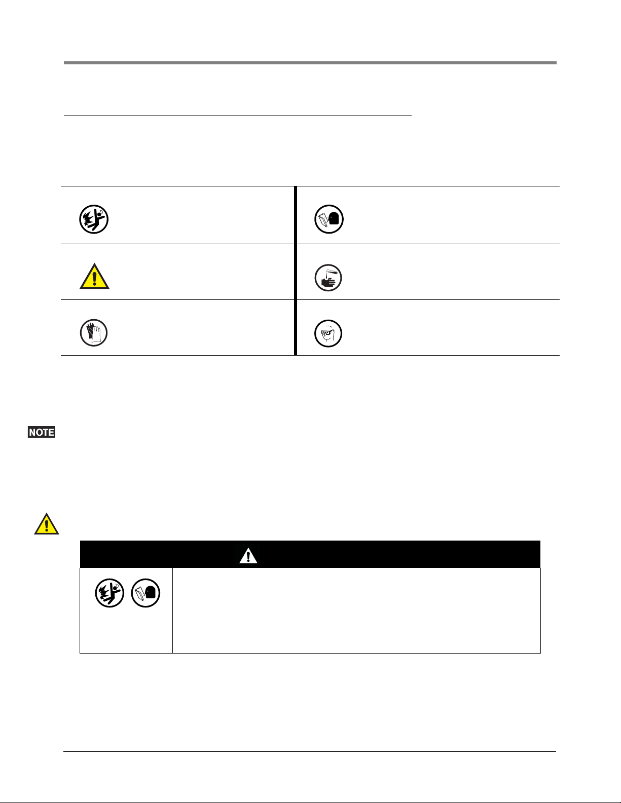
SAFETY SYMBOLS
The following safety symbols are used throughout this manual to alert you to important safety hazards and
precautions.
Explosive
Fuels and their vapors are extremely
explosive if ignited.
WARNING
Heed the adjacent instructions to avoid
equipment damage or personal injury.
GLOVES
Wear gloves to protect hands from irritation or injury.
Read All Related Manuals
Knowledge of all related procedures before you
begin work is important. Read and understand
all manuals thoroughly. If you do not understand
a procedure, ask someone who does
INJURY
Careless or improper handling of epoxy sealant
materials can result in bodily injury.
WEAR EYE PROTECTION
Epoxy sealant in contact with eyes can cause
serious injury. Always wear eye protection when
sealing wire splices.
GENERAL
Ensure that all local council, E.C. laws and regulations are complied with. Also ensure that all recognised safety
codes are followed.
Every person working with Veeder–Root equipment is expected to take every safety precaution possible in the
installation of TLS Systems.
Contractors must ensure that supervisory personnel on the installation site are aware of their presence and
requirements, especially the provision of safe working areas and isolation from AC electrical power.
Leaking underground tanks can create serious environmental and health hazards. It is the contractor's
responsibility to comply with the instructions and warnings found in this manual.
Substitution of specified components may impair intrinsic safety.
WARNING
Explosion could occur if other wires share ducts with intrinsically safe probe or
sensor wiring. Ducting for probes and sensors must not contain any other wiring
circuits except where permitted by local wiring codes and regulations.
FAILURE TO COMPLY WITH THE FOLLOWING WARNINGS AND SAFETY
PR ECAUTI ONS COULD CAU SE DAMAGE TO PROPE RTY, ENVI RON M ENT,
RESULTING IN SERIOUS INJURY OR DEATH.
EQUIPMENT PROTECTION
TLS monitoring equipment, including the Magnetostrictive Probe, is designed and certified to comply with the
Directive 94/9/EC (ATEX) and the IECEx scheme. The installer must consider any local regulations, which may
differ or be more stringent, prior to installing any equipment. The suitability/safety of any installation is ultimately
determined by the local authority having jurisdiction.
2
Page 7

TLS Magnetostrictive Probes International Installation Guide Health And Safety
The Magnetostrictive Probe that is part of the TLS Monitoring System is equipment Category 1 intended to be
installed in a Zone 0 hazardous location. Extreme care must be taken when determining the suitability of the
installation conditions and operation of the TLS Monitoring System. Procedures for installing either in a process
connection or riser pipe are detailed beginning on
aid in the determination if a probe is to be installed in a process connection or riser pipe:
1. Equipotential grounding of the installation site,
2. Minimizing static hazards associated with the underground storage of flammable liquids, and
3. Protection of the system against lightning strikes and any other source of possible electrical surges caused by
electrical railway systems, high voltage direct current facilities and the like.
page 13. At least the following items must be considered and will
EQUIPOTENTIAL GROUNDING
Consult any local regulations prior to installing a Magnetostrictive Probe into any tank. Veeder-Root supplies
approved process connections for installations where direct connection between the probe body and tank structure
is required (see Probe Installation Using Process Connection instructions below).
The intrinsically safe circuit in the TLS Monitoring System is derived from a fuse protected zener diode intrinsic safety
barrier. This type of explosion protection requires that the intrinsically safe electric circuit is referenced to the safety
ground associated to the mains circuit. If the site has a submersible pump (DIN/EN 15268) connected to the same
mains safety ground as the TLS Monitoring System Console and it is installed in a metallic riser of a metallic storage
tank, the zener diode barrier must be referenced to the same earth (safety) ground.
MINIMIZATION OF ELECTROSTATIC HAZARDS
Consult any local regulations prior to installing a Magnetostrictive Probe into any tank. Veeder-Root supplies
approved process connections for installations where direct connection between the probe body and tank structure
is required (see Probe Installation Using Process Connection instructions below).
The magnetostrictive probe housing complies with the 500 volt electrical strength requirements in IEC/EN 60079-
11. In addition, the probe housing provides an electrostatic dissipative path to the zener diode barrier earth ground
that must be referenced to the common grounding system. The electrostatic resistive path is less than 1 megohm.
All TLS Consoles provide an alarm if either of the two wires to the magnetostrictive probe is disconnected or short
circuited due to a malfunction.
If a probe must be serviced or replaced, observe any required relaxation time prior to opening any covers and
removing the probe.
LIGHTNING AND SURGE PROTECTION
Consult any local regulations prior to installing a Magnetostrictive Probe into any tank. Local rules or regulations may
require surge arrestors when installing equipment that crosses from a less restrictive zone, e.g., zone1 to zone 0
independent of the risk assessment. When required Veeder-Root can supply appropriate surge protection devices.
In locations where the intrinsically safe cables or circuits are considered to be at risk of developing hazardous
potential differences within Zone 0, an external surge protection device may be needed. Perform the lightning risk
analysis to determine if surge protection is required, and if necessary, the surge protector shall be installed in
accordance with IEC/EN 60079-25 and IEC/EN 60079-14. Reference
locations for a surge protector.
When they are deemed necessary, Veeder-Root requires the installation of external surge protection devices that are
classified as simple apparatus only. Only gas-discharge type surge protectors that comply with Clause 12 of IEC/EN
60079-25 are acceptable. Additional installation requirements for surge protection devices are defined in Clause
12.3 of standard IEC/EN 60079-14.
The Surge Risk Protection Assessment checklist (SRPA) is available on the Veeder-Root Tech Docs CD and on our
website at http://www.veeder.com/page/Probe_Manuals. An example of the SRPA appears in Appendix A of this
manual.
Figure 14 and Figure 15 for mounting
EC-TYPE CERTIFICATES FOR AN INTRINSICALLY SAFE SYSTEM
TLS Monitoring Systems are installed according to the conditions specified in the applicable Certificates. ATEX
Certificate Number DEMKO 06 ATEX 137480X and IECEx ULD 08.0002X are referred to as the system certificate
or parent certificate for all of the equipment in a TLS Monitoring System.
3
Page 8
TLS Magnetostrictive Probes International Installation Guide Before You Begin
Except for the cables used to connect intrinsically safe apparatus, information contained on the system certificate
and each of the device certificates, provide the safety related information (Ex ia) required to install a TLS
Monitoring System. Cables used to connect intrinsically safe apparatus must be considered in determining
compliance and are limited to the maximum allowable cable parameters listed in this manual. For assistance in
calculating the required (Ex ia) safety parameters, contact GVR as described on the inside cover of this manual.
For European Community (EC) installations, additional equipment compliance information is available on the EC
Declaration of Conformity including reference to the technical standards applied by the Notified Body in creating
the respective ATEX Certificates.
THESE ARE THE CONDITIONS FOR SAFE USE WHEN INSTALLING A MAG PROBE
1. The devices have been evaluated in conjunction with the intrinsic safety system defined in DEMKO 06 ATEX
137480X. The descriptive system documents and manuals included with the aforementioned certificate must
be followed during installation and the appropriate Veeder Root accessories must be used. Manual 577014031 details applicable process connections in accordance with EN 60079-26.
2. The following condition of safe use applies to the Mag Sump Sensor: Before installing or taking into a
hazardous area, earth the unit in a Safe Area to remove any static charge. Then immediately transport the unit
to the installation site; do not rub or clean the unit prior to installation. Cleaning is not required under normal
service conditions; do not rub or clean the device after installation. If the unit is not fixed to a known earth
point when installed, ensure that a separate earth connection is made to prevent the potential of static
discharge. When fitting or removing the unit, use of anti-static footwear & clothing is required.
3. The enclosure contains aluminum. Care must be taken to avoid ignition hazards due to impact of friction.
ATTENTION!
Important Considerations - Read Prior to Installation - Metallic/Steel Tanks
Process Connection (gland): Must be used in locations where it is mandatory that the Mag Probe be
equipotentially bonded to the tank structure.
Riser Pipe: May be used in locations that do not require bonding between the Mag Probe and the tank structure.
Reference European Norm IEC/EN 60079-14: Explosive atmospheres - Part 14: Electrical installations design,
selection and erection.
Cathodically Protected Tanks: Installation selection is dependent on the considerations listed above for the
Process Connection and the Riser Pipe.
Only install TLS Magnetostrictive Probes according to one of the four procedures listed below:
Wired Connections – Mag Probe to ATG Console wiring - see Figures 1 and 18.
1. Process Connection (gland) – Zone 1 installation, Surge Protector not required
2. Riser Pipe – Zone 0 installation, Surge Risk Protection Assessment (SRPA) required
Wireless Communication – Mag Probe with RF hardware - see Figures 2, 24 and 25
3. Process Connection (gland) – Zone 1 installation, surge protector not required
4. Riser Pipe – Zone 0 installation, Surge Protector required
Before You Begin
1. Consult any local regulations prior to proceeding to determine the best installation method. The instructions
below detail how to safely install probes with process connections or in a riser pipe and will also help in
determining when surge protection is required or may be necessary.
2. Depending on the considerations above, perform a Surge Risk Protection Assessment (SRPA) of equipment
in the site. A (SRPA) checklist is available on our website at http://www.veeder.com/page/Probe_Manuals.
3. Verify the equipment needed to complete the installation as described in this manual, and, if necessary, any
equipment required following completion of the site Surge Risk Protection Assessment (SRPA).
4
Page 9
TLS Magnetostrictive Probes International Installation Guide Procedures for Installing Mag Probes
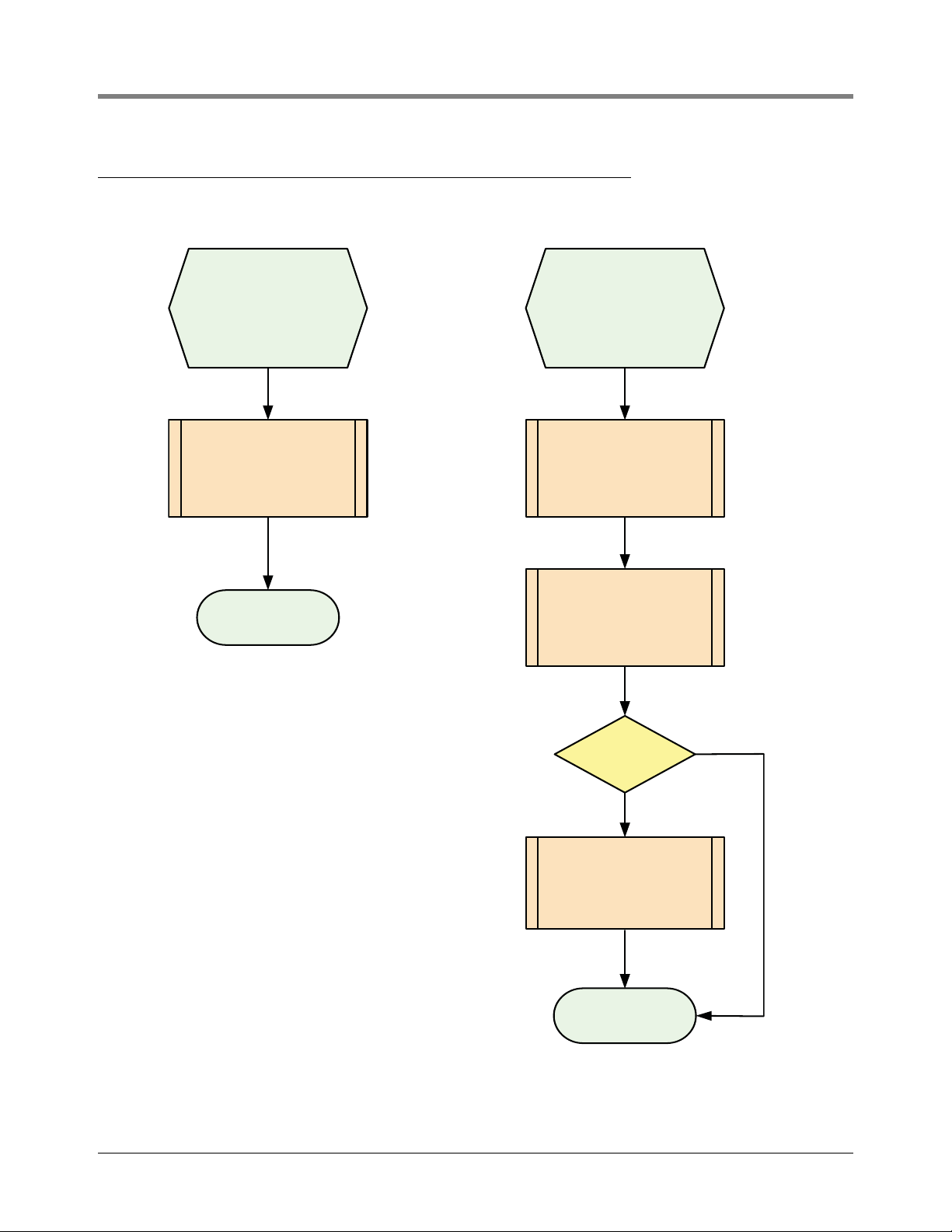
Procedures for Installing Mag Probes
Riser PipeProcess Connection
Procedure for installing Mag
Probes into storage tanks
using a tube gland.
NOTE: Use a tube gland in
locations where it is
mandatory that the Mag Probe
be equipotentially bonded to
the tank structure.
Install the Mag Probe with a
process connection according to
the instructions on Figure 14 of
this manual.
Procedure for installing Mag
Probes into storage tanks
using a riser pipe.
NOTE: Use a riser pipe in
locations that do not require
bonding between the Mag
Probe and the tank structure.
Install either a sleeve or an
adapter as shown on Figure 17,
then install the Mag Probe in a
riser pipe according to the
instructions on Figure 13 of this
manual.
Mag Probe
Installation Complete
Perform a surge risk protection
assessment (SRPA), located on
appendix page A-1 of this manual
to determine the possible use of a
dual channel surge protector for
the Mag Probe.
Is a
surge protector
required ?
Yes
Install a dual channel surge
protector, part number BA-350 or
848100-002, according to Figure
11 of this manual.
Mag Probe
Installation Complete
No
Figure 1. Procedures For Installing Mag Probes Using Wired Connections
5
Page 10
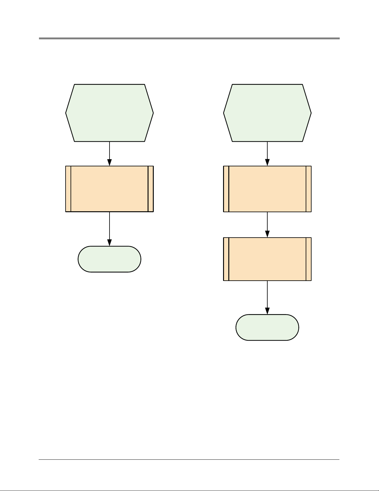
TLS Magnetostrictive Probes International Installation Guide Procedures for Installing Mag Probes
Mag Probe
Installation Complete
Install either a sleeve or an
adapter as shown on Figure 17,
then install the Mag Probe in a
riser pipe according to the
instructions on Figure 13 of this
manual.
Install a single channel surge
protector, part number 848100-
001, according to Figure 25 of
this manual.
Install the Mag Probe with a
process connection according to
the instructions on Figures 14 and
24 of this manual.
Riser PipeProcess Connection
Mag Probe
Installation Complete
Procedure for installing Mag
Probes into storage tanks
using a riser pipe.
NOTE: Use a riser pipe in
locations that do not require
bonding between the Mag
Probe and the tank structure.
Procedure for installing Mag
Probes into storage tanks
using a tube gland.
NOTE: Use a tube gland in
locations where it is
mandatory that the Mag Probe
be equipotentially bonded to
the tank structure.
Figure 2. Procedures For Installing Mag Probes Using Wireless Connections
6
Page 11

Mag Plus Probe Installation Kits
031-11
Cable
Probe cable connector
(attaches to threaded connector
on the top of probe canister)
These two wires connect in the J-box or splice kit
to the two field wires from the console.
Product float
Product float
Water float (optional)
Sleeves
2-Inch Floats
Water float (optional)
1-Inch Floats
Adapters
Water float (optional)
Product float
3- or 4-Inch Floats
Note: your Mag Probe installation kit will contain
1-inch, 2-inch, 3-inch or 4-inch floats and either
adapters or sleeves as per your order.
Boot
Cable tie
Encapsulant pack
Wire Nuts
Barrel, sleeve & end caps
031-15
The Mag Plus Probe Installation kit.
Cable Seal Kit
Figure 3. Mag Plus Probe Installation Kit 846402
Figure 4. Cable Seal Kit
7
Page 12

TLS Magnetostrictive Probes International Installation Guide Surge Protector Kits
Overvoltage arrestor
Terminal blocks
External connection (PA)
Ground wire
connection clamp
031-12
Surge Protector Kits
When required, a surge arrestor must conform to Clause 12 of IEC/EN 60079-25 and must be installed in
accordance with the requirements for surge protection devices defined in Clause 12.3 of standard IEC/EN
60079-14 as follows:
1. Surge protection is required between each conductor of the cable including the screen and the structure
where the conductor is not already bonded to the structure.
2. The surge protection device shall be capable of diverting a minimum peak discharge current of 10 kA (8/20 us
impulse according to IEC 60060-1 for 10 operations).
3. The connection between the protection device and the local structure shall have a minimum cross-sectional
area equivalent to 4mm
4. The cable between the intrinsically safe apparatus in Zone 0 and the surge protection device shall be installed
in such a way that it is protected from lightning.
5. Any surge protection device introduced into an intrinsically safe circuit shall be suitably explosion protected for
its intended location.
6. The use of surge protection devices which interconnect the circuit and the structure via nonlinear devices
such as gas discharge tubes and semiconductors is not considered to adversely affect the intrinsic safety of a
circuit, provided that in normal operation the current through the device is less than 10 uA.
2
copper.
For example, the two surge arrestors below, supplied by Gilbarco/Veeder-Root, are examples that comply with the
above requirements per the manufacturers declaration of conformity.
Figure 5. Surge Protector Kit For Wired Installations - Dual Channel Surge Protector BA-350 Or Equivalent
8
Page 13

TLS Magnetostrictive Probes International Installation Guide Process Connections
Cable tie
Encapsulant pack
Wire Nuts
Surge Protector
031-26
Probe leader cable gland*
50.8 mm (2”)
galvanised steel
riser cap
031-13
*Hummel probe leader cable gland
P/N: HSK-M-Ex, Size: M16X1,5 (IP68)
Ratings: II 2 G Ex e II
II 1 D Ex tD A20 IP6X
Cert No. KEMA 99ATEX6971X
Figure 6. Surge Protector Kit For Wireless Installations - Single Channel P/N 848100-001
Process Connections
A suitable process connection, IP67 minimum, is required for sealing a tank riser pipe or for forming an appropriate
boundary wall. The two riser caps/glands and process connection gland detailed below can be supplied by
Gilbarco Veeder-Root and are included on the manufactures type approval certificates DEMKO 06 ATEX
0508841X and IECEx UL 06.0001X and provide IP67 zone isolation and have been additionally subjected to a
10 bar pressure test.
51MM CAP AND GLAND
Figure 7. 51mm Threaded Riser Cap Assembly P/N 705-100-2203
9
Page 14

TLS Magnetostrictive Probes International Installation Guide Process Connections
Shield (if required)
Use fitting tool 705-100-3033
to install or remove the cap
3-inch (76mm) BSP riser cap
Probe leader cable gland*
Label
*Hummel probe leader cable gland
P/N: HSK-M-Ex, Size: M16X1,5 (IP68)
Ratings: II 2 G Ex e II
II 1 D Ex tD A20 IP6X
Cert No. KEMA 99ATEX6971X
76MM CAP AND GLAND
Figure 8. 76mm Riser Cap Assembly
MAG PROBE PROCESS CONNECTION (GLAND)
Olive
Locknut
1-inch BSP - 3/4” Coupling
031--23
Figure 9. Mag Probe Process Connection (Gland) P/N 501-000-1206
10
Page 15

Probe Installation
031-22a
Riser Assembly
Magnetostrictive
Probe
Dual Channel
Surge Protector
Field Cables
to Console
Tie Surge Protector (PA)
wire to the tank structure;
e.g., using a customer
supplied terminal lug.
Access Chamber Installation
GENERAL
The installation of the tank access chamber is the responsibility of the customer or their local site contractor and
not that of Gilbarco S.r.l. / Gilbarco UK. However, there are certain requirements which need to be met to allow
the correct installation of Veeder-Root in–tank monitoring probes. Typical installations are shown in
Figure 11.
Riser Assembly
Magnetostrictive
Depending
Probe
on probe type,
canister material
may be aluminum
or black conductive
polymer.
Figure 10 and
Field Cables
to Console
on probe type,
canister material
may be aluminum
or black conductive
polymer.
031-1
Figure 10. Typical Tank Lid Access Chamber Installation w/o Surge Protector
Depending
Figure 11. Typical Tank Lid Access Chamber Installation w/Surge Protector
To allow adequate space for probe installation and servicing, it is recommended that the access chamber is a
minimum 750mm deep and 600mm wide at the base. See Figure 12.
11
Page 16

TLS Magnetostrictive Probes International Installation Guide Access Chamber Installation
031-5a
1
1
1
Dual Channel
Surge
Protector
PROVISION FOR PROBE RISERS
A dedicated probe tapping of either 2-inch BSP (preferred), 3-inch BSP, or 4-inch BSP must be provided.
For maximum height–to–volume accuracy, the probe socket must be as close as possible to the longitudinal axis of
the tank.
The probe entry must not be obstructed by other pipe work. A free area above the probe socket of at least
100mm radius from its center must be provided. See Figure 12.
WARNING! The probe riser probe riser shall comply with IEC/EN 60079-26 and form a suitable process
connection across the boundary between zone 0 and zone 1 subject to the approval of the local authority.
Figure 12. Tank Lid Access Chamber — Critical Dimensions (in mm)
Where mechanical overfill prevention devices are installed, contractors must ensure that no part of these devices
will be obstructed when the probe and riser assembly are installed.
Failure to comply with this warning may result in the overfill prevention device not operating correctly.
12
Page 17

TLS Magnetostrictive Probes International Installation Guide Probe and Riser Installation Criteria
Probe and Riser Installation Criteria
Mag probe installations require a 2-inch or 3-inch (51 or 76mm) riser, regardless of tank entry size. Entry sizes of 1
inch, or entries larger than 3 inches must be with the suitable fittings.
The canister of the probe must be completely contained within the riser. In all cases, the probe must rest on the
bottom of the tank (see
Figure 13). Risers, when fitted, should be a minimum of 100mm above the probe canister.
76mm Entry51mm Entry
51mm Riser
Riser must be
51mm ID and free
of burrs.
76mm Riser
Boot
Note: The riser pipe cap forms a suitable
process connection at the boundary wall.
031-10
View 1 View 2
Installing with a
51mm Riser Pipe
Figure 13. Typical Probe Installations In Riser Pipe
Installing with a
76mm or 102mm Riser Pipe
13
Page 18

TLS Magnetostrictive Probes International Installation Guide Probe and Riser Installation Criteria
Probe leader cable
Probe canister
Encapsulated connection
Field cables to console
Flange
Tank lid
10mm (0.4”)
Minimum gap
1-inch BSPto 2-inch BSP reducer
included with 501-000-1207 kit
031-8
Boot
Zone 1 Installation
with Process Connection (Gland)
Process Connection (gland)
adapter P/N 501-000-1206
inlcluded with 501-000-1207 kit
PROBE INSTALLATION USING PROCESS CONNECTION
Certain installations may require a modified probe mounting arrangement consisting of a process connection
(gland) mounted directly to the tank lid as shown in
tapped G2 inch 11 tpi to DIN 2999 (BS2779) must be provided.
1. Prior to installing or servicing the Magnetostrictive Probe, remove the AC input power going to the TLS
Console and verify that the console power is off. During servicing, disconnect the probe cable and remove the
probe from the tank.
2. Reference Figure 14 to identify the hardware required to complete this installation.
3. Install the flange onto the tank lid then install the gland adapter. For 3-inch and 4-inch float sizes, install the
tube gland and the associated reducer onto the gland adapter prior to performing Step 4.
4. Prior to inserting the Mag Probe, install the tube gland on the probe shaft near the probe canister. Care must
be taken to ensure that the probe shaft is not harmed in any way.
5. Add the fuel float and the water float then install the plastic boot on the very bottom of the probe.
6. Insert the probe assembly into the tank and tighten the tube gland to the gland adapter.
7. Slide the Mag probe downward until the boot makes contact with the tank bottom. Lift the probe at least 10
mm (0.4 inch) from the bottom of the tank to account for thermal expansion of the probe. Tighten the tube
gland once the probe is at the appropriate height.
8. Connect the probe leader cable to the field wiring using the encapsulated splice kit shown in Figure 4.
Figure 14. Either a dedicated tapping or a suitable flange,
9. Restore power to the TLS Console and verify that the system is operating properly.
Figure 14. Installation Of A Mag Probe With A Process Connection (Gland)
14
Page 19

TLS Magnetostrictive Probes International Installation Guide Probe and Riser Installation Criteria
"B"
"E"
"A"
"D"
"C"
A - Tank diameter (internal)
B - Tank bottom to top of tank lid
C - Height of probe entry
D - Probe entry size
E - Vertical clearance for riser assy, above tank lid at probe entry
Dimensions
031-6
DETERMINING THE CORRECT PROBE LENGTH
Refer to Figure 15 and carry out the following procedure.
1. Enter dimensions A, B, C, and E in Tab l e 1.
2. Add dimensions B + C and enter this in column “F”.
3. Select a standard probe length that is equal to or greater than the dimension in column “F”.
Enter the standard probe Length in column “G”.
Figure 15. Dimensions Needed To Calculate Custom Probes And Risers
15
Page 20

TLS Magnetostrictive Probes International Installation Guide Probe and Riser Installation Criteria
DETERMINING THE MINIMUM ACCESS CHAMBER DEPTH
The minimum access chamber depth, is calculated as follows:
1. To the chosen standard probe Length (“G”), add 290mm, this is the overall probe length; enter this in column
“H”.
2. From the overall probe Length subtract dimension “B + C” (bottom of tank to top of probe flange); the result is
the minimum access chamber depth. Enter in column “I”.
3. Calculate the actual access chamber depth, dimension “E” minus dimension “C” and enter in column “J”
4. Calculate the probe clearance (“J” – “I”) and enter in column “K”.
Column “K” must be zero or a positive number. If the result is a negative number there is insufficient clearance
for the probe and riser assembly. In this case please contact Veeder-Root Technical Support or your local
Representative for details on custom length Mag Probes and special skirted risers, having available the
dimensions A - E shown in
Figure 15.
Table 1. Calculation sheet for determining the correct probe length
TANK
No.
1
2
3
4
5
6
7
8
9
10
11
12
A B C E
F
Bottom of
Tank to Top
of Probe
Entry
“B”+“C”
G
Standard
Probe
Length
H
Overall
Probe
Length
“G”+290mm
I
Minimum
Access
Chamber
Depth
“H”-”F”
J
Actual
Access
Chamber
Depth
“E”-”C”
K
Probe
Clearance
“J”-”I”
13
14
15
16
16
Page 21

TLS Magnetostrictive Probes International Installation Guide Probe Riser Pipe Installation
Hummel probe leader
cable gland
Hummel probe leader
cable gland
51mm Threaded Riser Cap Assembly
Shield (if required)
Use fitting tool 705-100-3033
to install or remove the cap
3-inch (76mm) BSP riser cap
76mm BSPT Riser Cap Assembly
50.8mm (2”)
galvanised steel
riser cap
031-3
Probe Riser Pipe Installation
A riser assembly consisting of a riser (either 2- or 3-inch [50.8 or 76mm] nominal bore galvanised steel pipe
threaded 2- or 3-inch BSPT at each end) and a 2- or 3-inch riser cap, designed specifically for the efficient
installation of Veeder-Root magnetostrictive probes, should be used for Mag Probe installation (see
Riser caps are normally fitted at the time of probe installation by Veeder-Root authorised engineers. An optional
cable shield is available for 3-inch (76mm) riser caps, if required.
Non–standard or locally supplied risers may be made from 2- or 3-inch nominal bore galvanised steel pipe
threaded 2- or 3-inch at each end (see
Tabl e 2 for allowable riser dimensions).
Remove the plug from the tank socket. Install a 2-inch (50mm nominal bore) or 3-inch (80mm nominal bore) riser
using an appropriate thread-sealing compound. Reducers are available for 4-inch (102mm nominal bore) sockets.
If the probes are not to be installed immediately, cap the riser.
Where locally supplied, 2-inch risers should be seamless, have a 2-inch ID, and be free of burrs.
Figure 16).
DN Nom Pipe
(mm)
25 1 26.65 1.049 29.34 1.155 29.08 N/A
50 2 52.51 2.067 47.63 1.875 46.86 55
80 3 77.93 3.068 76.58 3.015 75.82 85
100 4 102.26 4.026 95.63 3.765 94.87 110
NPS Nom Pipe
DN = Diameter Nominal, NPS = Nominal pipe size, Pipe type is iron or schedule 40 steel
*Maximum allowable inside diameter for Mag Probe installation.
(inch)
Figure 16. Veeder-Root Riser Cap Assemblies
Table 2. Dimensions for Steel Riser Pipes and Mag Probe Floats
ID Nom Pipe
(mm)
ID Nom Pipe
(inch)
OD Max Float
(mm)
OD Max Float
(inch)
17
OD Min Float
(mm)
ID Max* Pipe
(mm)
Page 22

TLS Magnetostrictive Probes International Installation Guide Probe Riser Pipe Installation
Probe
canister
Up
Probe shaft
Settings for 3" Riser
Settings for 4" Riser
Fit adapters
at each end of
the canister.
Make sure
locking tabs
snap into
grooves in
canister.
Sleeve Assembly - 2” Riser
123
4
Adapter Assembly - 3” & 4” Risers
PROBE SPACER ASSEMBLY
See Figure 17 for example probe sleeve/adapter assembly instructions.
Figure 17. Example Probe Canister Sleeve/Adapter Assembly
18
Page 23

TLS Magnetostrictive Probes International Installation Guide Probe Riser Pipe Installation
ZONE 1 HAZARDOUS LOCATION
Nonhazardous Area
Zone 0
Hazardous
Location
AC
Mains
Equipotential
Bonding Conductor
4 sq.mm
Common
Grounding
System
Probe includes
resistive circuit of
750K to discharge
electrostatic charges.
ATG
Console
Earth
Ground
U
m: 250 V
Intrinsically Safe
Barrier Circuit
Intrinsically Safe
ground
INV.
Tank 1
Tank 2
Tank 3
Shielded Two-Core Cable
for intrinsically safe wiring
Storage Tank
Vapours
Tank Structure
Cable
Bushing
Probe Riser
Pipe with Cap
Magnetostrictive
Probe Enclosure
Sleeves or
adapters
Swimmer
(Liquid product Float)
Swimmer
(Water Float)
Liquid Storage Tank
Storage Tank
Liquid
Probe Boot
(+)
(-)
(+)
(-)
(+)
WHITE
BLACK
Encapsulation Enclosure or
Weatherproof Box
(+)
(-)(-)
(+)
WHITE
Dual Channel Surge Protector
BLACK
To ATG
From
Probe
From
Probe
To ATG
SURGE PROTECTION NOT REQUIRED SURGE PROTECTION REQUIRED
OR
Optional Simple Apparatus
Mount within 1 meter of the
probe riser pipe.
(PA)
(PA)
Note: Each ATG and Magnetostrictive
Probe contains internal surge protection
devices (tranzorbs not shown).
Figure 18. Connection Diagram For A Mag Probe In A Riser Pipe With And Without Optional Surge Protection
19
Page 24

TLS Magnetostrictive Probes International Installation Guide Field Wiring
Splice enclosure cap
TLS cable
Probe cable
51mm
Shield wire
76mm
Black
White
White
Black
031-17
Field Wiring
PROBE TO TLS CONSOLE
Pull appropriate cable from the each probe location to the TLS console.
Explosion could occur if other, non–intrinsically safe wires share TLS intrinsically safe wire conduits or wiring
troughs. Conduits and wiring troughs from probes and sensors to the console must not contain any other wires.
At least 2 metres of free cable must be left for connection at both the TLS console and the probe locations.
Ensure that all cables are correctly identified. All probe field wiring must be legibly and permanently labelled with
the tank number.
Failure to correctly mark probe field wiring may lead to re-work, delays in system installation and additional
charges.
MAXIMUM CABLE LENGTHS
A maximum of 305 metres of cable length per probe must be observed.
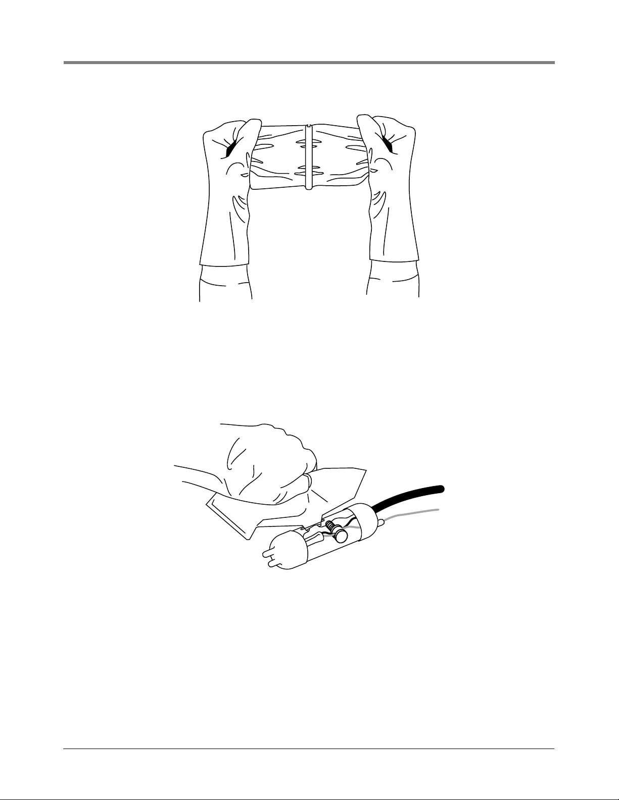
SPLICING PROBE FIELD WIRING
1. Insert the probe cable through the top of each riser cap and through the Hummel cable leader bushing.
2. Cut the soft vinyl epoxy enclosure end cap entrance holes to accommodate each cable diameter. Keep the
hole sizes to a minimum. Insert about 127mm of each cable through the openings [
of the outer jacket from each cable. Trim the insulation from the conductors.
Figure 19]. Remove 76mm
Figure 19. Splice Length Dimensions
20
Page 25

TLS Magnetostrictive Probes International Installation Guide Field Wiring
Cable from TLS
Black (–) pair
Aluminum bonding clamp
White (+) pair
Enclosure sleeve
Bare drain wire (cut back to
cable jacket)
Cable from probe
031-16
3. Make the connections using wire nuts [Figure 3]. Cut off the bare shield wire at the cable jacket.
Figure 20. Splice Connections
4. Use the aluminum bonding clamp to hold the cables together (finger tighten, being careful not to damage the
conductor insulation, see
Figure 20). This clamp is not intended to make any electrical connections.
5. Center the splice in the clear plastic sleeve. Assemble the splice closure, making sure the sleeve is fully
inserted into each of the vinyl end caps. Rotate the sleeve cover until both openings line up. Place the splice
on a level surface.
WARNING!
Vapor and liquid may cause sensitization Contains isocyanate. May be
irritating to the eyes. Avoid skin and eye contact. Avoid repeated and
prolonged breathing of vapor. Use only in well ventilated areas.
Inhalation - provide fresh air. In case of eye contact flush eyes with plenty of
water for 10 minutes and get medical attention. If ingested do not induce
vomiting. Get medical attention. Wash with soap and water in case of skin
6. Remove bag of “Sealing compound” from foil package. Grasp the ends, one in each hand, then pull sharply to
remove plastic clip [
Figure 21].
contact.
21
Page 26
TLS Magnetostrictive Probes International Installation Guide Field Wiring
Figure 21. Removing Sealing Compound Clip
7. Thoroughly mix compound together. Invert bag several times while squeezing compound from one end to the
other for a minimum of one minute.
8. Once the mixture feels warm, immediately cut one corner and slowly fill the plastic sleeve. Stop just short of
filling the entire sleeve. Do not overfill. [
Figure 22. Pouring Sealing Compound Into Sleeve
Figure 22]
9. With a twisting motion, rotate the outer clear plastic barrel to close the pouring slot.
10. Wait at least five minutes, then use the large cable tie to mount the splice to the riser pipe or probe canister as
applicable (see
Figure 23).
22
Page 27
TLS Magnetostrictive Probes International Installation Guide Surge Protector
031-18
Figure 23. Securing Splice Enclosure With Cable Tie
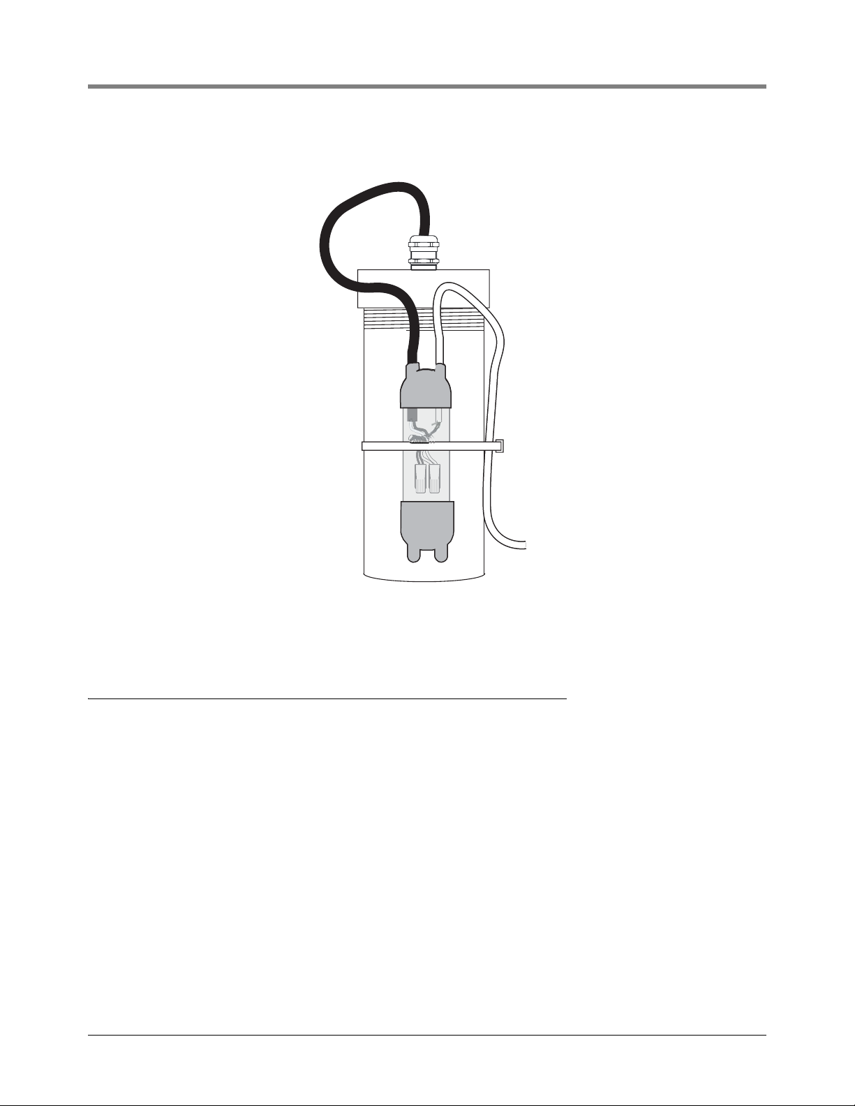
Surge Protector
INSTALLATION (IF REQUIRED)
When surge protection is required, mount the surge protector as close as possible to the entry point for the probe
leader cable. The surge protector is not polarity sensitive so either cable port may be used for the probe leader
cable. Use the cable port on the opposite side for the wiring coming from the ATG Console. Inside the surge
protector, one side of each spark gap device is wired to the metal enclosure. Use a bonding strap, with a minimum
size of 4 sq. mm, to wire the enclosure to the tank structure using the external potential equalization (PA) terminal.
Connect the wires from each cable as shown in
Figure 24.
23
Page 28

TLS Magnetostrictive Probes International Installation Guide Surge Protector
031-24.eps
Battery
Connection
Battery
Connection
Tie wrap cables
Transmitter
(far side of
bracket)
Battery pack
(this side of
battery support
bracket)
Cable from surge
protector
Red battery labels
two places
Single Channel
Surge Protector
S.P. Connection
Typical Detail
Bond 4 mm2 wire
locally to tank
Pre-installed piping,
e.g., Dip Tube
Probe cable
Process connection (Gland)
Tank flange
W
B
W
B
Y/G
40mm
150mm
Battery
Connection
Battery
Connection
Tie wrap cable
Transmitter
(far side of
bracket)
Battery pack
(this side of
battery support
bracket)
Cable from surge
protector
Red battery labels
two places
Single Channel Surge Protector Install surge arrestor within 1m
of tank entry
S.P. Connection
Typical Detail
Bond 4 mm2 wire
locally to tank
Riser
Tank flange
W
B
W
B
Y/G
Tie wrap cable
40mm
150mm
031-28.eps
Figure 24. Example Wireless Installation With Process Connection And Single Channel Surge Protector
Figure 25. Example Wireless Installation With Riser Pipe And Single Channel Surge Protector
24
Page 29
Appendix A - Surge Protection Risk Assessment
Where a tank gauge probe is installed in a ‘riser’ and the entire probe is within the vapour space of the tank, a risk
assessment is required to assess whether additional surge protection is required in close proximity to the probe.
First, complete the Lightning Risk Assessment by identifying whether the site is suitably described by one of the 6
categories listed. Where required, a lightning ground flash density number can be estimated from the lightning
map on the following page. Tick the box next to the description that best describes the site. If none of the
descriptions apply, then do not tick any box. In this instance, additional surge protection is required in close
proximity to the probe.
Second, step through the overall Surge Risk Assessment. For each statement, tick either True or False. Additional
surge protection is required if any of the statements are False.
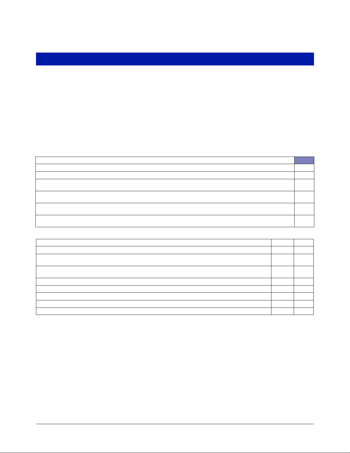
LIGHTNING RIS K ASSESSM ENT - is the site described by one of the following categories? If yes, tick the relevant box
The site is in a town, village, or built up area
The site is a large motorway site with no probe cable extending more than 5m beyond the area covered by the canopy
The site is a large motorway site with no probe cable extending more than 10m beyond the area covered by the canopy and the
lightning ground flash density is less than 3.38
The site is a large motorway site with no probe cable extending more than 15m beyond the area covered by the canopy and the
lightning ground flash density is less than 2.25
The site is a large motorway site with no probe cable extending more than 20m beyond the area covered by the canopy and the
lightning ground flash density is less than 1.88
The site is in open country with no probe cable extending beyond the area covered by the canopy and the lightning ground flash
density is less than 1.13
SURGE RISK ASSESSMENT Tru e False
A lightning risk assessment has been performed as above and the site falls into one of the categories identified
The installation of the tanks and/or probe is more than 100m away from an electric railway, underground railway, or
tram line
The installation of the tanks and/or probe is more than 100m away from other high voltage sources such as power turbines
The site does not have high voltage power cables supported by pylons passing overhead
The installation does not use above ground tanks
The site is not used for high blend ethanol fuels
The probe cable is buried under the forecourt
The site does NOT use cathodic protection for the tanks
Delete as appropriate
Additional surge protection is not required at this site since all entries in the SURGE RISK ASSESSMENT table
above are marked as TRUE.
Additional surge protection is required at this site since one or more entries in the SURGE RISK ASSESSMENT
table above are marked as FALSE
Site name Date Signatory
Download the Risk Assessment Tool at http://www.mygvr.com/
A-1
Page 30
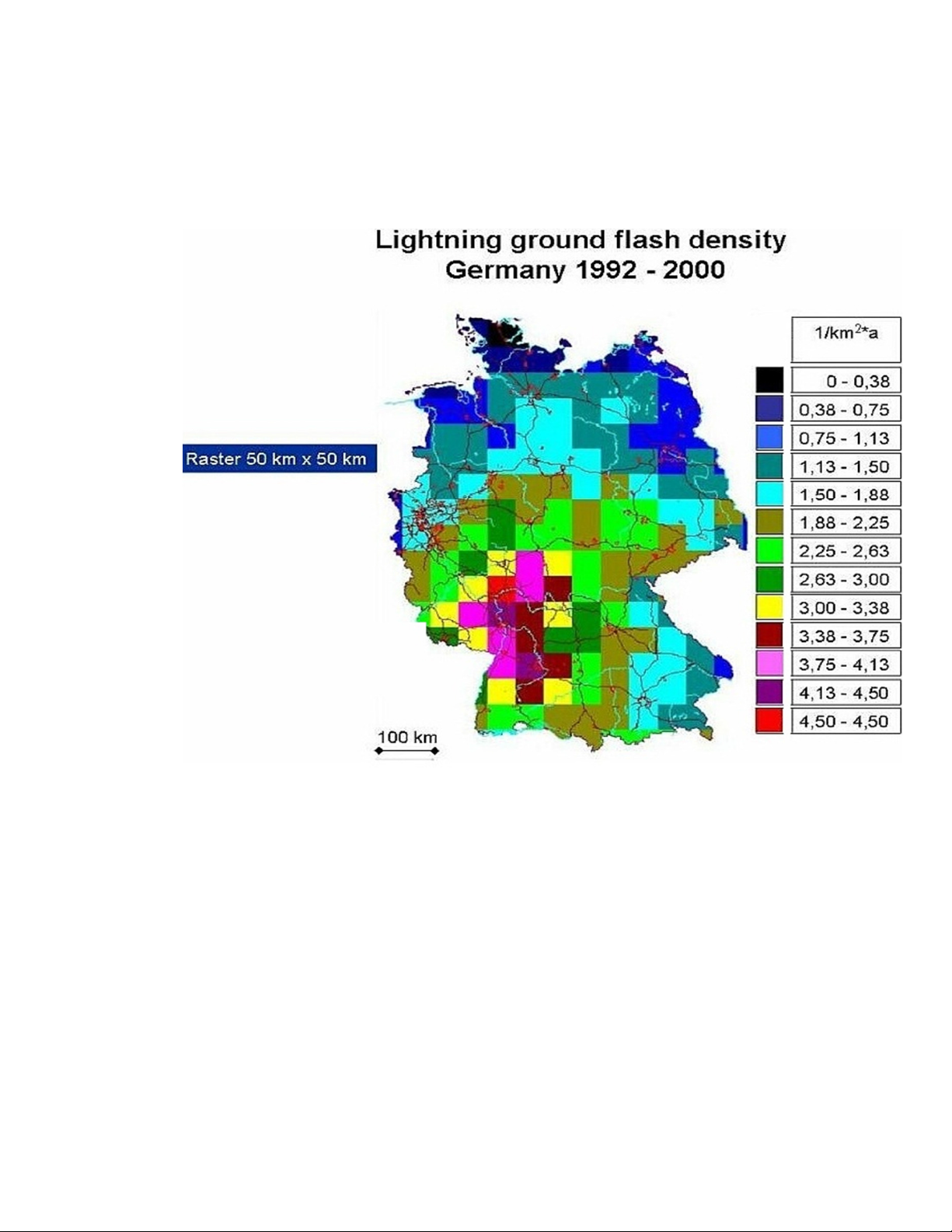
Example Isokeraunic Map from IEC Lightning Risk Assessment Tool: Germany
Page 31

For technical support, sales or
other assistance, please visit:
www.veeder.com
 Loading...