

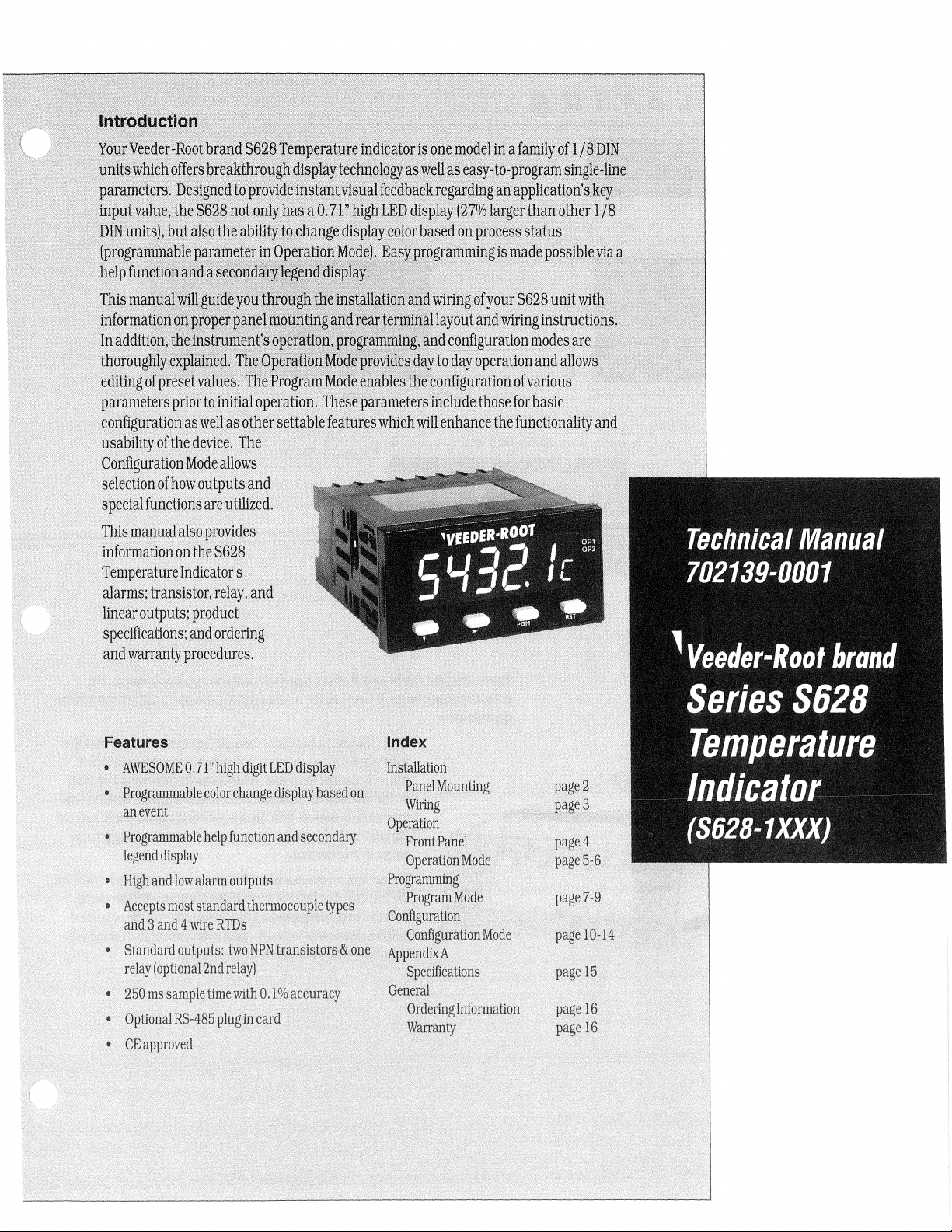
Veeder Root Series C628 Temperature Indicator INSTALLATION, OPERATION AND SERVICE INSTRUCTIONS
Page 1
Cfhtt~~etiori~{'
...
····y0l1FWed~r"~ootRtarldS6~8~errtP~ffitureifldi~at~rj1!ol1enr~deUn.afamlly·oflIa·PINit
...••...
'
.mlitswhiehQfffrspre¥tbHiqg~fli$pt~y~~c1m(}1{}gya~~elt~.ei~)T7tO~Rr(lgtamsingle-l}~~.:)
para~ters.D:signedto
~npl}.t
valuer
tl1eS~2$n.otonlJ'~a~~~.1T'!1i~tE.D/d~splfY(2'l%iarger
.•
bINJu~it~hbutals9ttie!iPi~~tcr~ti~g\4is'playcRlQrbas~d
.
.(pr~tamIll0:~~eR·
)'l1elpfun~~~Fia1!a
'
.. ' ...
editfn~of
• i
parameteis,p~iortOjHil'ialoper~tiob.·Tne$ep~~ain~tersi,n.Gll.laetn()~eforbasie
prese~1i~l1ie~:
configuratiOnqSlvelJ
usal?ilityoHhedevice,
Qonfiguratibn
sele<;tiprf
speci~1l1.u1cfi
Mqde
of
how
ou.tp:tu.sarid
qnsareqtiIizect,
pioviMi~starit¥JStJ,alf~.dbacki\gardlUganappnC!lti~n!~~tjf;.··'>·
1hrotot{leillfY
onpro~es~s~atus
.
1'fie
JonMJ1~~l;J~,~sYPfcDg~arrtrningisIlladepp§Sitile~iJa.a
"
...
:...
.
~~ik\Vi;tifgOfYout~q28~~i~tg~t;
,.,
"
XOllfaqd~ringJnstructiO,ri~i:
.i
•.. '
.•
e()nfig~au9Ilmddesar~</}f
~~yto~aJ()per~tionandatlQwsr:
Progi~w{M:64~~~a
•
".
i"
••
~~p?tifigu.fatianof\Tarfous
'..
•....•.....
.
'.
" .
. .'.,
....
...•
•..
..
a~.
piner
settaolefe<l,fllteS
The
whi.ehWilt~nlian.GetbefunctibnalitY<1nd·
.'
.
.,..
.
allows'
Thisrnanualalsoprovide
infofntationOlJ
.
Temperature
aiatms;.trans~stot,
Itnew
outptfts;
specifiG(itions;
andwana.
theS628.
Indicator's
product
and,
ty
procedures.;·
l1
s
relay,
and·
prdering
Page 2
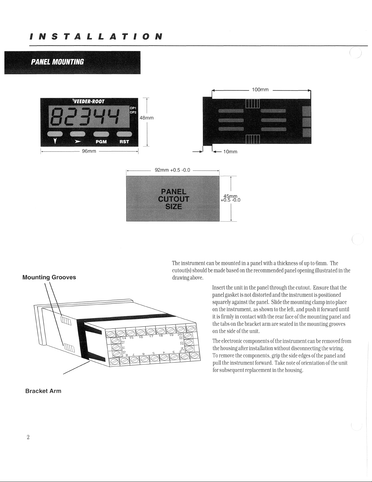
INSTALLATION
PANEL
MOUNTING
1
48mm
Mounting Grooves
Bracket Arm
The
instrument
cutout(s)
drawing
should
above.
can
be
be
made
Insert
panel
squarely
on
it
is
the
on
The
the
To
pull
for
mounted
based
on
the
unit
gasket
is
against
the
instrument,
firmly
in
contact
tabs
on
the
the
side
of
electronic
housing
after
remove
the
the
instrument
subsequent
in a panel
in
not
bracket
the
components
components,
with a thickness
the
recommended
the
panel
distorted
the
paneL
as
shown
with
arm
unit.
installation
forward.
replacement
through
and
Slide
to
the
the
rear
are
seated
of
the
without
grip
Take
in
the
of
panel
opening
the
cutout.
the
instrument
the
mounting
left,
and
face
of
the
in
the
instrument
disconnecting
the
side
edges
note
of
orientation
housing.
up
to
6mm.
illustrated
Ensure
is
positioned
clamp
push
it
mounting
mounting
can
be
of
the
The
that
into
place
forward
panel
grooves
removed
the
wiring.
panel
and
of
the
in
the
the
until
and
from
unit
(
2
Page 3
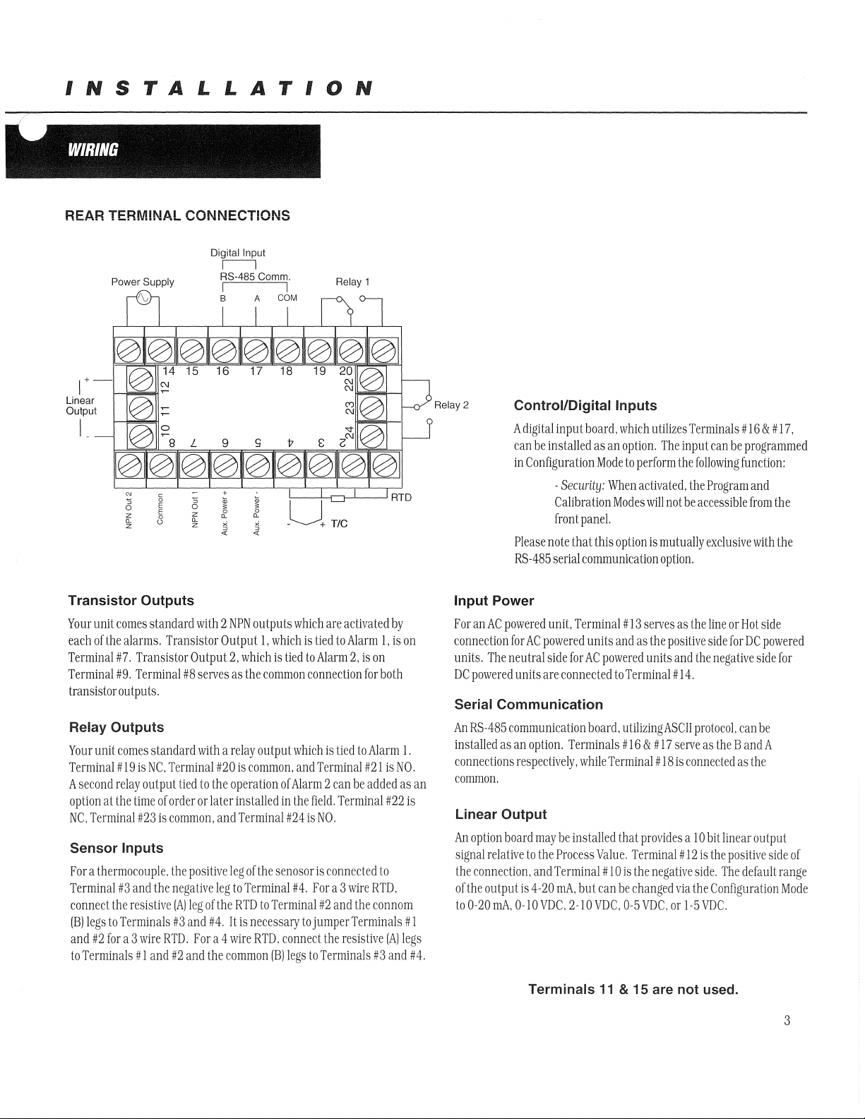
INSTALLATION
WIRING
, , ,
~
~
~"
~
, J
\.
REAR TERM!NAL CONNECTIONS
Digital Input
II
Power Supply
RS-485 COI1lI1l.
I I
B
COM
1+-
Linear
Output
1-+~"'fI
I
~
N
C
~
0
E
z
0
(L
0
z
~
0
z
(L
z
+
ru
~
(L
x
.ii'
ru
~
(L
~
<t
_U+
Relay 1
TIC
RTD
Relay 2
Control/Digital
A
digital
input
board,
can
be
installed
in
Configuration
-
Security:
as
Mode
Calibration
front
panel.
Please
note
that
this
RS-485
serial
communication
Inputs
which
an
option.
to
When
Modes
option
utilizes
The
perform
activated.
will
not
is
mutually
option.
Terminals # 16
input
can
be
the
following
the
Program
be
accessible
exclusive
& #
17.
programmed
function:
and
from
the
with
the
Transistor
Your
unit
each
of
Terminal
Terminal
transistor
Relay
Your
unit
Terminal # 19
A
second
option
NC.
Terminal
Sensor
Outputs
comes
the
alarms.
#7.
Transistor
#9.
Terminal
outputs.
Outputs
comes
is
relay
at
the
time
#23
Inputs
standard
standard
NC.
outpul
or
is
For a thermocouple.
Terminal
connect
(B)
and
to
#3
the
legs
to
Terminals
#2
for
a:3
Terminals
and
the
resistive
wire
# I
and
with 2 NPN
Transistor
Output
#8
serves
with a rclay
Terminal
tied
to
order
or
common.
the
positiVE'
negative
(Al
leg
of
#3
and
RID.
For
#2
and
Output
#20
the
later
and
leg
the
#4.
a 4
the
outputs
1.
2.
which
as
the
common
output
is
common.
operation
installed
Terminal
leg
of
the
to
Terminal
RTD
to
It
is
necessary
wire
I~TD.
common
which
are
which
is
tied
is
tied
to
Alarm
connection
which
is
and
Terminal
of
Alarm 2 can
in
the
field.
#24
is
NO.
senosor
is
connected
#4.
For
a 3
Terminal
#2
tojumperTerminals
connect
the
(B)
legs
to
Terminals
activated
to
Alarm
2,
is
for
ned
to
Alarm
#21
be
added
Terminal
wire
and
the
resistive
by
1.
is
on
on
both
1.
is
NO.
as
#22
is
10
RTD.
connom
# 1
(AJlegs
#3
and
an
#4.
Input
Power
For
an
AC
powered
connection
units.
The
DC
powered
Serial
Communication
An
RS-485
insta
Hed
as
connections
common.
Linear
An
signal
th"
onhe
to
Output
option
board
relative
connection.
output
0-20
mA.
unit,
Terminal
for
AC
powered
neu
lral
side
for
units
are
connected
communication
an
option.
Terminals # 16
respectively,
may
to
and
is
4-20
0-10
Terminals
while
be
installeclthat
the
Process
Terminal # 10
mAo
but
VDC,
2-10
units
AC
powered
board,
Value.
can
VDC.
11
and
to
Terminal
#
13
serves
as
as
the
positive
units
and
Terminal # 14.
ulilizingASClI
& #
17
serve
#]8
is
provides a 10
Terminal # 12
is
the
negalive
be
changed
0-5
& 15 are
VDC.
via
or
not
the
line
or
side
the
negativE'
protocol.
as
the B and
connected
bit
linear
is
the
positive
side.
The
the
Configuration
\-5
VDC.
used.
Hot
for
can
as
default
side
DC
powered
side
be
A
the
output
for
side
range
of
Mode
3
Page 4
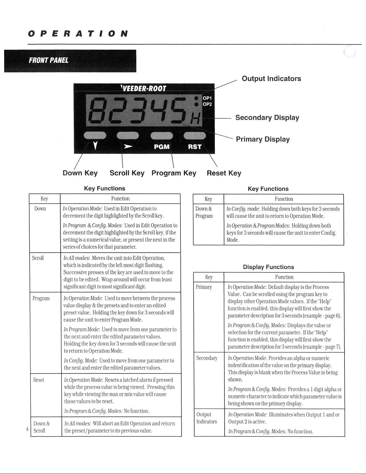
OPERATION
~
IfRtlNl
p h""'
Key
Down
PANEL
'~"'>
~', • "~
Down
In
decrement
In
decrement
setting
series
Key
Key
Functions
Operation
Program & Config.
Mode:
the
digit
the
digit
is a numerical
of
choices
for
Used
highlighted
highlighted
that
~
Scroll Key
Function
in
Edit
Operation
by
the
Modes:
Used
in
by
the
value.
or
present
parameter.
Program
to
Scroll
key.
Edit
Operation
Scroll
key,
the
next
in
if
the
the
to
Key
Reset Key
Key
Down
&
Program
Output
Secondary
Primary
Key
Functions
In
Config.
mode:
Holding
will
cause
the
unit
In
Operation & Program
keys
for 3 seconds
Mode.
Indicators
Display
Display
Function
down
both
to
return
to
Operation
Modes:
Holding
will
cause
the
unit
keys
for 3 seconds
Mode.
down
to
enter
both
Config.
Scroll
Pmgmm
Reset
Down
4
Scroll
&
111M
modes:
Moves
which
is
indicated
Successive
digit
significant
In
Operation
value
preset
cause
In
Program!1JIode:
the
Holding
to
return
In
ConJig.
the
111
Operation
while
key
those
in
Program & Conjlg.
I1lAH
the
presses
to
be
ediled.
digit
Mode:
display & the
value.
Holding
the
unit
next
and
enter
the
key
to
Operation
Tvlode:
next
and
enterthe
TvIode:
the
process
while
viewing
values
to
modes:
'Will
preset/parameter
the
by
the
of
the
Wrap
to
most
significant
Used
presets
the
to
enter
Program
Used
the
edited
down
for 3 seconds
Mode.
Used
to
edited
Resets a latched
value
the
max
be
reset.
IvIodes:
abort
to
unit
into
Edi t Operation.
left
most
digit
key
are
used
around
will
digit.
to
move
between
and
to
enler
key
down
Mode.
to
move
from
parameter
move
from
parameter
is
beingvit'wed.
or
min
value
No
function.
an
Edit
Operation
its
previous
flashing.
to
move
to
occur
!J'om
least
the
process
an
ediled
for 3 seconds
Olle
parameter
values.
will
cause
the
one
parameter
values.
alarm
if
pressed
Pressing
will
cause
and
return
value.
the
will
unit
to
this
to
Key
PJimary
I
I
Secondary
Output
Indicators
Display
[11
Operation
Value.
Can
display
other
function
parameter
I
111
selection
I
function
parameter
In
indcnHikation
This
shovm.
In
numeric
being
In
Output 2 is
in
is
Program & Con[ig.
for
is
Opemtion
display
Program
character
shown
Opermion
Progmm
Functions
Function
Mode:
Oefa
be
scrolled
using
Operation
enabled,
description
enabled,
description
&,
&.
this
for 3 seconds
IHodes:
the
current
this
[or 3 seconds
Mode:
Provides
of
the
value
is
blank
when
ConIig.
"VJodes:
to
indicate
on
the
primary
1,10de:
lIluminates
active.
Conflg.;'\Jodes:
ul t display
the
program
Mode
values.
dispJaywill
Displays
parameter.
display
will
an
alpha
on
the
primaf1j
the
Process
Provides
which
display.
when
No
functioll.
is
the
Process
key
to
If
the
"Help'
first
show
the
(example -page
the
value
If
Ihe
"Help"
first
show
the
(exampJe -page
or
numeric
display.
Value
is
being
a 1
digit
alpha
parameter
Output I and
value
6).
or
7).
or
is
or
Page 5
OPERATION
OPERATION
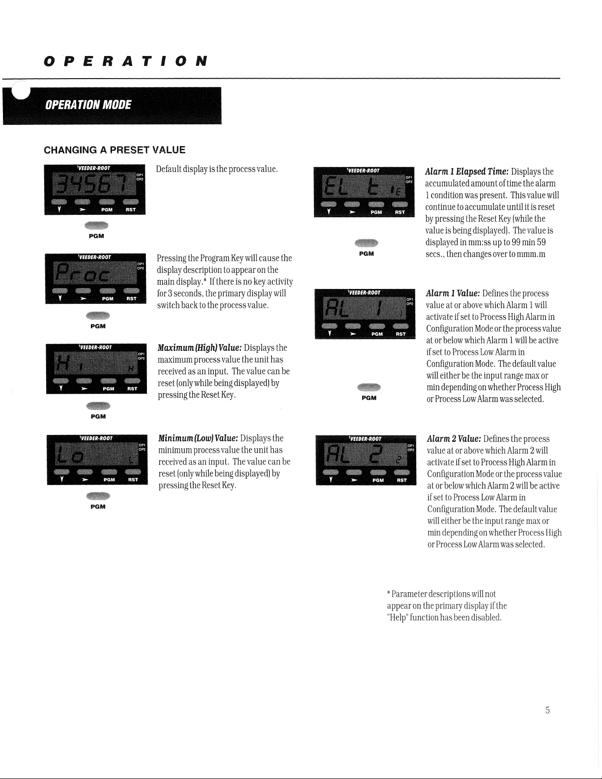
CHANGING A PRESET VALUE
:~l:
,~,:
Y
----
MODE
'VEEDER·Roor
.~~
.~/:~~
~i!:~::
>-
PGM
RST
PGM
PGM
Default
Pressing
display
main
for 3 seconds.
switch
Maximum
maximum
received
reset
pressing
display.
(only
display
is
the
Program
description
*
If
the
back
to
the
(High)
process
as
an
input.
while
the
Reset
the
process
Key
to
appear
there
primary
process
Value:
value
The
being
displayed)
Key.
will
is
no
display
value.
Displays
the
value
value.
cause
on
key
unit
the
the
activity
will
the
has
can
be
by
PGM
PGM
Alarm 1
accumulated
by
value
Elapsed
1
condition
continue
displayed
sees.,
Alarm 1
value
activate
Configuration
at
if
set
Configuration
will
min
or
to
pressing
is
being
in
then
Value:
at
or
if
set
or
below
to
Process
either
be
depending
Process
was
accumulate
the
changes
above
which
Low
Time;
amount
present.
Reset
displayed).
mm:ss
up
over
Defines
which
to
Process
Mode
or
Alarm 1 will
Low
Alarm
Mode.
the
input
on
whether
Alarm
Displays
of
time
the
This
value
until
it
Key
(while
The
to
99
min
to
mmm.m
the
process
Alarm 1 will
High
Alarm
the
process
in
The
default
range
max
Process
was
selected.
alarm
is
reset
the
value
59
be
active
value
or
the
will
is
in
value
High
PGM
PGM
Minimum
minimum
received
reset
(only
pressing
(Low)
process
as
an
while
the
ReseL
Value:
value
input.
being
Key.
Displays
the
unit
The
value
displayed)
the
has
can
by
be
~
Parameter
appear
on
"Help"
function
Alarm 2
value
activate
Configuration
at
if
Configuration
will
min
or
the
Value:
at
or
above
if
set
or
below
set
to
Process
either
be
depending
Process
Low
df:scriptions
primary
display
has
been
Defines
to
Process
Mode
whicl1
Low
Mode.
the
inpu 1 range
on
Alarm
will
not
disabled.
the
which
Alarm 2 will
High
or
the
process
Alarm 2 will
Alarm
in
The
det'aultvalue
whether
Process
was
selected.
if
the
process
Alarm
value
be
active
max
or
in
High
5
Page 6

OPERATION
OPERATION
MODE
Continued
OTHER OPERATING DISPLAYS
z
y
y
'VEEDER·ROOT
,:""
v~
~
PGM
'VEEDER·ROOT
~
PGM
~
RST
RST
0"
0"
0"
0"'
Over
Range
process
input
full
Under
process
input
full
value
Range
value
CHANGING AN ALARM VALUE
'VEEDER·ROOT
y
'VEEDER·ROOT
Y >--
~
~
PGM
PGM
PGM
RST
5Times
RST
0"
0",
0"
0",
Default
From
the
through
values
display
the
until
Display:
becomes
scale
Appears
higher
value.
Display:
becomes
scale
Process
other
value.
is
the the
Value
Operation
lower
Alarm 1 appears.*
than
Appears
than
Process
display,
Mode
if
the
if
the
Value.
scroll
the
the
/'
f
y~
7
Y
Y
'VEEDER·ROOT
i'
Y
h>o-
PG~ < ~;;v
'VEEDER·ROOT
~
PGM
'VEEDER·ROOT
~
PGM
Sensor
0"
0"'
unit
two
~
Use
0"
0"
right
to
from
RS;~
significant
0"
0",
The
RST
seconds.
the
be
Use
digit
9.
Break
does
not
Scroll
and
highlight
changed.
the
least
digit.
the
Down
until
the
display
Display:
receive
Key
to
the
Wrap
Significant
Key
to
desired
will
wrap
Appears
an
input
signal
move
from
digit
that
around
will
to
the
decrement
value
appears.
around
from 0 to
if
left
needs
occur
most
the
G
the
for
to
Y
'VEEDER·ROOT
>-
PGM
RST
To
0"
0"
Scroll
for 3 seconds,
appear
secondary
Scroll
now
the
change
Key.
(one
Key
be
in
most
the
Alarm
If
there
the
Alarm
digit
description
display);
in
order
Edit
Operation
significant
value,
was
no
value
however,
to
edit.
as
digit
flashing.
press
key
activity
will
shown
press
The
unit
signified
the
the
**
on
will
by
y
*
Parameter
appear
on
"Help"
function
PGM
PGM
'VEEDER·
ROOT
~
PGM
deSCriptions
the
primary
has
display
been
0"
0"'
RST
will
not
if
disabled.
After
the
changed,
the
new
appear
flashing
again
and
appear
the
desired
press
value.
on
the
digits.
the
parameter
on
the
**
Edit
accessed
been
digits
the
Program
The
new
main
display
Press
main
display.
Operation
if
the
enabled
have
been
Key
value
without
the
Progam
description
cannot
Preset
in
Program
to
will
Lock
enter
any
Key
will
be
has
Mode.
6
Page 7

PROGRAMMING
PROGRAM
_
~
ENTER!~JG
The
Program
Operation
for 3 seconds.
The
name
on
the
Successive
scroll
parameters
Program
seconds.
*
Parameter
main
disabled
,-"
Mode
of
primary
presses
the
display
Mode.
display
in
Program
MOBE
""
PROGRAtv~
Mode
can
be
accessed
by
holding
the
the
first
parameter
display.*
ofthe
Program
through
the
in
the
hold
names
if
the
Program
the
Program
wiII
not
"Help"
Mode.
Mode.
appear
function
rv10DE
from
Program
will
appear
Key
remaining
To
exit
Key
for
on
the
has
K
At~D
the
Key
will
3
been
~
BASIC OPERATiON
[or 3 seconds
PGM
PGM
3
sees.
~
or
PGM
Edit
Operation
Pressing
3
the
seconds
parameter.
indicate
the
parameter.
display
will
Program
pressed
unit
MSD
activity
enter
the
value
page
Mode.
(instead
is
in
Edit
flashing.
for 3 seconds.
Edit
scroll
as
in
6.
Press
changes.
Scroll
will
display
The
secondary
one
digit
The
digil
flash
to
If
the
of
Operation.
If
there
Operation
and
edit
Operation
the
Key
or
no
key
activity
the
value
for
that
display
will
identifier
in
indicate
Scroll
the
secondary
the
Key
for
the
unit
was
waiting 3 seconds).
as
indicated
had
been
no
press
the
scroll
(MSD
flashing).
buttons
to
change
Mode.
described
Program
Key
La
enter
is
by
key
key
Use
the
for
in
the
the
to
on
any
PARAMETER SEQUENCE
PGM
Retransmission
Coryigumtion
Function:
to
the
Ac1justmenl
Default
mode)
Detlnes
minimum
Rang!:':
Value:
the
output
-19999
-19999
Scale
lower
signal
to
Minimum
end
of
the'
99999
linear
(Appears
scale
for
only
q'a
retmnsmL,siml
the
retransmission
output
output
has
by
defining
been
the
enabled
value
ill
equated
7
Page 8

PROGRAMMING
PROGRAM
MODE
PGM
PGM
PGM
Continued
Retransmission
Confl[Juration
Function:
to
the
Adjustment
Default
Process
Function:
Adjustment
Default
Input
Function:
any
extraneous
AdjustmentRange:
Default
mode)
Defines
the
maximum
Value:
Value:
Value:
output
Range:
99999
Variable Offset
Corrects a known
Range:
0.00
Filter
Time
Filters
the
impulses
2.0
Scale Maximum
upper
end
of
the
signal
-19999
to
99999
offset
of
the
-19999
to
99999
input
over a user
0.0
(Om
to
100.0
(Appears
linear
scale
input
in
definable
for
order
time
only
the
period
if
a
retransmission
retransmission
to
more
accurately
to
minimize
output
output
display
the
effect
has
by
defining
the
on
been
process
the
Process
enabled
the
value
value
Value
in
equated
of
Communication
Function:
Adjustment
Default
PGM
Baud
Function:
AdjusimentRange:
Default
PGM
8
Defines
Value:
Rate
Selects
-
1200BPS
Value:
Range:
Address
the
unique
1
to
1
(Appears
the
serial
4800
(Appears
communication
99
only
({communication
communication
2400
only
speed
BPS
if
address
board
communication
of
the
is
instal1ecl
board
inSlllJment
and
4800
is
installed
aciioated)
BPS
and
activated)
9600
BPS
Page 9

PROGRAMMING
...
PGM
Display Color Change
Function:
AdjustmentRange:
Red:
always
Default
Alarm Lock
Function:
Adjustment
The
-
be
Value:
display
Defines
the
will
red
Green
Determines
Range:
color
of
to
Red
whether
the
display
Green:
-
always
the
The
display
be
green
Alarm
for
prior
Values
to
will
can
and
Green
display
when
is
red
active
be
changed
after
the
-
no
present.
when
to
Red:
will
alarm
via
preset
be
green
It
will
either
the
value
is
The
condition
turn
alarm
is
front
panel
reached
Red
display
no
alarm
present.
when
active
to
Green:
-
either
will
The
be
red
condition
It
will
turn
alarm
when
is
green
is
PGM
Enable:
Alarm
values
-
viewed
and
changed
Default
Value:
Enable
Help Prompt
Function:
seconds
Adjustment
Help -Yes:
parameter
appear
display.
associated
parameter
pressing
waiting
Default
Determines
prior
to
Range:
Multi-character
-
descriptions
on
the
primary
Thevalue
with
will
the
scroll
for 3 seconds
Value:
that
appear
can
be
whether
the
parameter
will
by
key
or
Help -Yes
Disabled:
-
read
only
the
multi-character
value
Help -No:
-
parameter
appear
on
display.
The
be
identified
in
the
secondary
Alarm
values
appearing
Only
the
values
will
the
primary
parameter
by a single
display
are
parameter
can
digit
name
will
appear
on
the
main
display
for
3
9
Page 10

CONFIGURATION
CONFIGURATION
- '
ENTERING CONFIGURATION MODE AND BASIC OPERATION
The
Configuration
from
the
Operation
Down
and
Program
The
name
of
the
on
the
primary
display.
Successive
scroll
parameters
exit
Program
*
Parameter
main
disabled
presses
the
display
in
the
Configuration
Keys
for 3 seconds.
names
display
if
in
Program
MODE
Mode
can
Mode
by
Keys
for 3 seconds.
first
parameter
*
of
the
Program
through
the
the
Conflguration
Mode,
hold
will
not
"Help"
function
Mode.
be
accessed
holding
will
Key
remaining
Mode.
the
Down
appear
has
the
appear
will
To
and
on
the
been
PGM
for 3 seconds
3
sees.
-+
or
PGM
Edit
Operation
Pressing
3
parameter.
indicate
parameter.
display
Configuration
pressed
unit
MSD
activity
enter
the
value
page
changes.
seconds
the
will
(instead
is
in
flashing.
for 3 seconds,
Edit
scroll
as
6.
the
Scroll
will
The
one
The
flash
Edit
Operation
and
in
Operation
Press
Key
or
no
display
the
value
secondary
digit
digit
to
Mode.
of
Operation,
If
there
edit
the
display
identifier
in
the
secondary
indicate
If
the
Scroll
waiting 3 seconds),
as
had
press
(MSD
Hashing).
buUons
to
Mode,
Program
key
activity
for
that
will
for
the
the
unit
Key
indicated
been
no
the
scroll
change
described
Key
to
enter
is
was
by
key
key
Use
the
for
in
the
the
to
on
any
10
Page 11

CONFIGURATION
CONFIGIJRATION
PARAMETER SEQUENCE
MODE
Continued
..
PGM
Input Range
Function:
Adjustment
Selects
J
T
K
N
B
R
S
RTD
3
wire
RTD
4
wire
Range:
the
See
100
IlO
200
210
300
310
400
500
600
700
800
810
900
910
input
table
sensor
below
101
III
201
2Il
301
3Il
401
501
601
701
801
811
901
9Il
type,
-200
-128
-240
-128
-240
-128
100
-200
-128
-200
-128
resolution,
1200
1372
1399
0
1824
1760
0
1760
0
537
400
400
537
800
537
800
537
and
display
-328
-198.4
-400
-198.4
-400
-198.4
32
212
32
32
-328
-198.4
-328
-198.4
scale
2192
998.6
752
752.0
2502
998.6
2550
3315
3200
3200
1472
998.6
1472
998.6
roc
or
OF)
by
means
of a code
number
..
PGM
..
PGM
Range Trim High
Function:
Adjustment
Default
Range Trim Low
Function:
AdjustmentRange:
Default
Adjusts
Range:
Value:
Adjusts
Value:
the
Range
Range
the
Range
Range
maximum
trim
max
.
minimum
min.
min
.
range
value
low
[specified
range
value
[specified
in
of
the
in
next
of
the
above
input
type
parameter)
input
type
table)
to
range
selected
to
range
selected
trim
max.
high
[specified
[specified
in
in
previous
above
table)
parameter)
II
Page 12

CONFIGURATION
CONFIGURATION
MODE
Continued
Power Supply Frequency
Function:
ensure
input
AdjustmentRange:
Although
proper
power
the
filtering
instrument
of
the
input
is
designed
signal,
to
it
is
necessary
handle
either
to
set
50
the
or
60
input
Hz
inputs
frequency
automatically,
of
the
primary
(
to
~
PGM
~
PGM
50Hz
-
Default
Value:
60
Alarm 1 Type
Function:
AdjustmentRange:
Process
activate
value
the
Default
Alarm 2 Type
Function:
Adjustment
Sets
the
High:
Alarm
-
when
the
equals
or
exceeds
Alarm 1 setting
Value:
Process
Sets
the
Range:
process
action
will
High
action
60Hz
-
of
the
alarm
to
one
of
the
Process
Low:
Alarm
the
or
one
will
process
is
less
of
the
- -
activate
when
value
equals
than
the
Alarm 1 setting
Alarm
of
the
alarm
to
following
No
Alarm:
activate
following
choices:
Alarm 1 will
choices:
be
12
~
PGM
Process
High:
-
activate
when
value
equals
the
Alarm 2 setting
Default
Value:
Alarm
the
process
or
exceeds
No
will
Alarm
Process
Low:
Alarm
the
or
will
process
is
less
- -
activate
when
value
equals
than
the
Alarm 2 setting
No
Alarm:
activate
Alarm 2 will
be
Page 13

CONFIGURATION
c
CONFIGURATION
Y-
" '" " , '"
MODE
Continued
~
~
~
Output 1 Usage
Function:
Adjustment
Alarm
DirectAction:The
will
is
once
condition
1,
Non
be
On
activate,
the
Alarm
Determines
Range:
latching,
output
when
Alarm
and
turn
1
is
no
longer
present
LogiCCLI
OR
oj
Alarm
DirectAction:The
will
be
On
OR
condition
Alarm 1 and
output
when a logical
between
Alarm 2 is
present
how
Off
1
&.
the
1
2,
transistor
Alarm
ReverseAction:
output
Alarm 1 is
turn
I
condition
Logical
2,
Reverse
output
logical
between
Alarm 2 is
1,
will
Off
OR
will
OR
and
Non
latciling,
be
On
inactive,
when
the
is
present
oj
Alarm
Action:
be
On
condition
Alarm
not
present
relay
The
when
land
for
and
Alarm
1
&.
The
when
output 1 will
Alarm
Action:
On
when
activate,
only
when
front
panel
a
operate
1.
Latching,
The
output
Alarm 1 is
and
reset
turn
Direct
OfT
via
will
the
be
Alarm
1,
Reverse
Action:
output
will
Alarm 1 is
turn
OiT
via
the
front
Latching.
The
be
On
inactive,
only
when
panel
when
and
reset
POM
PGM
Dejault
Value:
Alarm
Output
Function:
AdjustmentRange:
Alarm
The
when
and
Alarm 2 condit
longer
Dejewll
2,
Direct
output
Alarm
lurn
present
Value:
2 Usage
Determines
Action:
will
be
2 is
activate.
Orf
once
ion
Alarm
On
the
is
I ,
Non
latching,
how
the
Al.arm2.
The
when
and
no
Alarm 2 condition
present
2.
Direct
DireciAction
transistor
ReverseAc/ion:
output
Alarm 2 is
turn
Off
Actiol1
and
will
when
relay
for
be
On
inactive,
the
is
output 2 will
Logical
DirecUlction:The
will
OR
operate
OR
of
be
On
when a logical
condition
AJarm 1 and
present
Alarm
1 &
output
between
Alarm 2 is
2.
Logical
OR
2,
Rel'erseActioll:The
oUlput
will
logical
OR
between
Alarm 2 is
of
Alarm
be
On
condition
Alarm
not
present
when
land
1 &
a
13
Page 14

CONFIGURATION
CONFIGURATION
MODE
Continued
Retransmission Output
Function:
Adjustment
Selects
Range:
the
range
of
the
retransmission
()
output
~
PGM
None
Default
Value:
None
Option Selection
Function:
AdjustmentRange:
Default
Determines
No
-
Value:
Input
None
0-5
Volts
-
the
function
Communication:
will
be
communication
DC
of
the
used
board
for
RS-485
0-10VoltsDC
installed
The
slot
in
the
option
Security:
digital
Program
Configuration
cannot
When
-
input
and
be
is
accessed
slot
the
active,
Modes
0-20mA
the
4-20mA
14
Page 15

"
~ 1 ~.
APPENDIX
SPECIEICA'lIONS
" '" :
'"-
..
",
~ ~ ~
Types:
Accuracy:
Sample
Resolution:
Sensor
,~-
Rate:
Break:
~
-"
B.
J.
3
wire
±O.
250ms
14
bits
Detected
I-~ '"
"';(
K.
N.
S.
and
and 4 wire
1%
of
span
within 2 seconds
A
_
~
~"~
-!
~C'l
~
TThermocouples.
RTDs
Communication
Type:
Data
Format:
Physical
Layer:
MaximumZones:
Baud
Rate:
Serial
asynchronous,
Open
ASCII:
One
bits,
one
stop
bit
RS-4S5
99
Seleclablefrom
UART
to
UART
start
bit,
even
parity
9600,4800.2400.
or
seven
1200
data
Control
Inputs
Type:
Logic:
Impedance:
Response
Time:
Function:
Outputs
Solid
State:
Relay:
Latency:
linear
Outputs
Ranges:
Accuracy:
Resolution:
Update:
Load
Impedence:
Approvals
General:
EMC
Susceptibilit.y:
EMC
Emissions:
Safety:
Sinking.
Low
4.
Edge
-"
2.0
VDC.
7llCl
to
tVoltage -Sourcing
25ms
Programmable
NPN
open
collector.
SPDT,
5Aresistive@
75
fl
seconds.
0-20mA.
±O
.25%
degrades
8
bits
4-20mA.
(mA
linearly
in
250m3
plus
at
ApprOximately
mA
Ranges:
500[1
CE
Complies
EN50082-2:
Complies
EN50081-2:
Complies
with
1995
with
1994-
v.ilh
Sensitive
High..;:
3.0
30
VDC
llOVAC
8
1115
for
O-lOV.
2-lOV.
250Q.
Vat
2kQ):
io
±O.
5%
(10
bits
in
4/s
max.; V Ranges:
EN50082-J:
EN500S1-1:
EN5]
0 I
0·1:
max.
relay
Is
typ.)
1992.
1992,
1993
100
pull-in
0·5V.
500Q
mA
J-5V
max.
min.
Electrical
SupplyVoltage:
Power
Consumption: 4 Watts
Access.
Power
Supply:
Display
Type:
Height:
Annunciators:
Physical
Dimensions:
Mounting:
Terminals:
Front
Panel
Rating:
Case
Material:
Weight:
Environmental
Operating
Storage
Helative
Temp.:
Temp.:
Humidilv:
90-264
VAC,
24
VDC @ 30
Red/Green, 7 segment
display,
single
0.71"
(lSmm)
0.3"
(7mmJ
Output
1 & 2 status
4Smm x 96mm,
Panel
mount
45mmx
92mm
Screw
type -combination
NEMA
4X/IEC
.
GELexan
0.551bs.
0"
to
55°
Celsius . .32°
-200 to
80°
20%
to
95%
50/50
Hz,
or
20-50
mA
LED, 5 digits
digit
secondary
primmydisplay.
secondalydisplay
11
Omm
deep
(mounting
bracket
cutout
head
IP55
94-0
to
Celsius.
_4°
10
non-condensing
VAC/VDC
primary
display
supplied).
1.310 Fahrenheit
176"
Fahrenheit
15
Page 16

GENERAL
ORDERING
INFORMA
TlON
5628 - 1 Q
2nd Relay Option
o None
1 2nd
Relay
Linear Output
Option
o None
3 Linear
~
----'
Output
'-------
Low Voltage
Power Supply
2
(leave
Serial Communication
Option
o None
5 RS-485
6 Digital Input
Yes
blank
if
does
not
apply)
WARRANTY
Standard
free
from
workmanship
Company,
product
the
of
conditioned
defects
and
obligation
Company
be
Printed
702139-0001
August, 15 1998
Revision none
products
from
defects
the
date
is
Company
products
or
in
the
returned
in
in
of
shipment,
or
material
at
no
charge
actually
hereunder
that
fall
upon
deficiency
case
of
of
the
Company
is
able
to
to
the
U.S.A.
manufactured
workmanship
and
will
be
to
the
Buyer.
defective
within
receipt
components
obtain
Company
rests
shall
the
by
the
promptly
shall
from
without
be
after
by
the
and
material
products
repaired
Final
with
the
limited
foregoing
Company
discovery
or
units
purchased
not
exceed
the
supplier
its
Company
for a period
which
are
or
replaced,
determination
Company.
solely
to
repair
limitations,
of
written
within
by
the
settlement
thereof.
prior
consent.
are
warranted
defective
at
the
as
The
obligation
and
and
shall
notice
of
the
warranty
the
Company,
that
No
products
Products
to
be
of
one
year
in
option
of
the
to
whether
of
replacement
be
any
alleged
period,
the
the
shall
which
the
Company
Company's
accept
defective.
extent,
a
WARRANTY
APPLICATIONS
UNLESS
WRITING
IT.
THE
OTHER
LIMITED
FORA
consents
factory.
invoices
for
unauthorized
The
life
of
upon
the
type
AS
TO
FITNESS
BY
THE
THE
COMPANY
AFTER
THE
FOREGOING
WARRANTIES
TO
PARTICULAR
WARRANTY
ANY
WARRANTY
to
have
returned
The
Company
repairs
the
products
of
usage
thereof,
OF
ITS
BUYER
NORAS
SPECIFICALLY
PROPOSED
IS
EXPRESSED
OF
PURPOSE.
shall
be
shipped
cannot
assume
to
its
components,
of
the
Company
and
THE
COMPANY
PRODUCTS
USAGE
EXCLUSIVE
OR
MERCHANTABILITY
FOR
TO
PERIOD
AGREES
HAS
BEEN
AND
IMPLIED,
•
F.O.B.
responsibility
depends,
SPECIFIC
OF
SERVICE
OTHERWISE
MADE
IN
LIEU
INCLUDING,
OR
OF
Danaher
1675 Delany Road
Gurnee,
IL
Phone: 847.662.2666
Fax:
the
or
even
though
to a large
MAKES
NO
IN
KNOWN
TO
OF
ALL
BUT
NOT
FITNESS
Controls
60031-1282
847.662.663~
16
 Loading...