

Page 1
Introduction
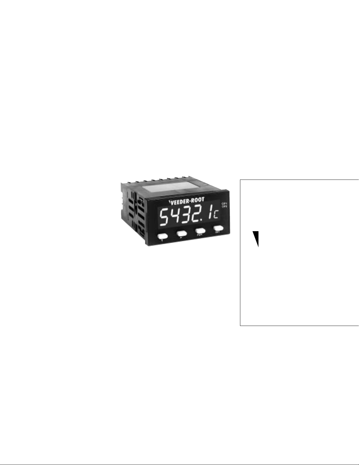
Your V eeder-Root brand C628 Position Indicator is one model in a family of 1/8 DIN units
which offers breakthrough display technology as well as easy-to-program single-line
parameters. Designed to provide instant visual feedback regarding an application’s key
input value, the C628 not only has a 0.71” high LED display (27% larger than other 1/8
DIN units), but also the ability to change display color based on process status
(programmable parameter in Operation Mode). Easy programming is made possible via a
help function and a secondary legend display.
This manual will guide you through the installation and wiring of your C628 unit with
information on proper panel mounting and rear terminal layout and wiring instructions.
In addition, the instrument’s operation and programming modes are thoroughly
explained. The Operation Mode provides day to day operation and allows editing of
preset values. The Program Mode enables the configuration of various parameters prior
to initial operation. These parameters include those for basic configuration as well as
other settable features which will enhance the functionality and usability of the device.
This manual also provides
information on the C628
Position Indicator’s alarms;
transistor, relay and linear
outputs; product
specifications; and ordering
and warranty procedures.
Technical Manual
702138-0002
Features
• AWESOME 0.71” high digit LED display
• Programmable color change display based on
an event
• Programmable help function and secondary
legend display
• High and low alarm outputs
• Optional linear output relative to position
• Accepts encoder inputs
• Filter speed settable for 20, 200, or 10,000 Hz
• Standard outputs: two NPN transistors & one
relay (optional 2nd relay)
• Front panel reset enable and alarm lockout
• Optional RS-485 plug in card
• CE approved
Index
Installation
Panel Mounting page 2
Wiring page 3
Operation
Front Panel page 4
Operation Mode page 5
Programming
Program Mode page 6-9
Appendix A
Specifications page 10
General
Notes page 11
Ordering Information page 12
Warranty page 12
Veeder-Root
brand
Series C628
Position
Indicator
(C628-2XXX)
Page 2
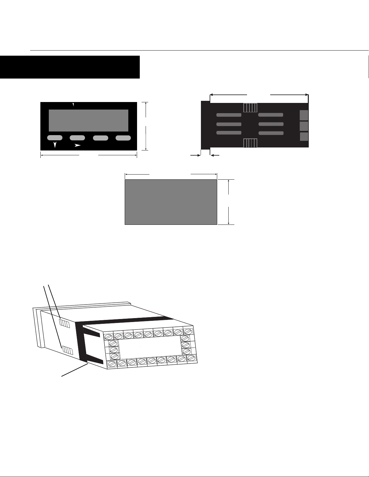
INSTALLATION
PANEL MOUNTING
100mm
82344
Mounting Grooves
VEEDER-ROOT
PGM
96mm
OP1
OP2
48mm
RST
92mm +0.5 -0.0
CUTOUT
14 15 16 17 18 19 20
10 11 12
10mm
PANEL
45mm
+0.5 -0.0
SIZE
The instrument can be mounted in a panel with a thickness of up to 6mm. The
cutout(s) should be made based on the recommended panel opening illustrated in the
drawing above.
Insert the unit in the panel through the cutout. Ensure that the
panel gasket is not distorted and the instrument is positioned
squarely against the panel. Slide the mounting clamp into place
on the instrument, as shown to the left, and push it forward until
it is firmly in contact with the rear face of the mounting panel and
the tabs on the bracket arm are seated in the mounting grooves
on the side of the unit.
22
23
24
2
345 678
The electronic components of the instrument can be removed from
the housing after installation without disconnecting the wiring.
To remove the components, grip the side edges of the panel and
pull the instrument forward. Take note of orientation of the unit
for subsequent replacement in the housing.
Bracket Arm
2
Page 3
INSTALLATION
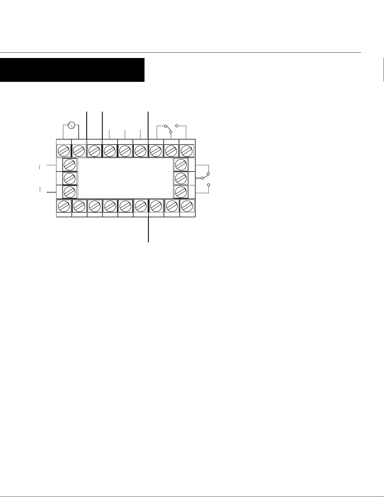
WIRING
REAR TERMINAL CONNECTIONS
+
Linear
Output
(opt.)
-
Power Supply
+ VDC -
14 15 16 17 18 19 20
10 11 12
RS-485 Comm.
(opt.)
B A
COM
Relay 1
22
23
23 4 5 6 78
24
Relay 2
(opt.)
Input Power
For an AC powered unit, Terminal #13 serves as the line
or Hot side connection for AC powered units and as the
positive side for DC powered units. The neutral side for
AC powered units and the negative side for DC powered
units are connected to Terminal #14.
NPN Out 2
(LO)
Common
NPN Out 1
(HI)
Digital In 2
(sec. lockout)
Digital In 1
(rem. reset)
Aux. Power
(opt.)
Input A
Input Common
Input B
Count Inputs
Terminal #2 is the connection for Input A, which is used for channel A of
an encoder input. Terminal #1 is the connection for Input B, which is
used for channel B of an encoder input. The common connection for
both Input A and Input B is Terminal #3.
Transistor Outputs
Your unit comes standard with 2 NPN outputs which are activated by
each of the alarms. Transistor Output 1, which is tied to the High Alarm
V alue, is on Terminal #7. Transistor Output 2, which is tied to the Low
Alarm Value, is on Terminal #9. Terminal #8 serves as the common
Control/Digital Inputs
A contact closure or NPN signal can be used to activate preconfigured
functionality. Terminal # 5 is used for a remote reset function, while
Terminal #6 is a security function, that when active, will prohibit entry
into Program Mode. Terminal #8 serves as the common for both of these
inputs.
connection for both transistor outputs.
Relay Outputs
Your unit comes standard with a relay output which is tied to the High
Alarm Value. Terminal #19 is NC, Terminal #20 is common, and
Terminal #21 is NO. A second relay output tied to the Low Alarm V alue
can be added as an option at the time of order or later installed in the
Auxiliary Power Output
field. Terminal #22 is NC, Terminal #23 is common, and Terminal #24 is
NO.
A 9 - 15 VDC for powering external sensors and encoders up to 125 mA
can be accessed by connecting the positive supply side of the sensor to
Terminal #4 and the negative side to Terminal #8.
Serial Communication
An RS-485 communication board, utilizing ASCII protocol, can be
installed as an option. Terminals #16 & #17 serve as the B and A
Linear Output
An option board may be installed that provides a 10 bit linear output
connections respectively, while Terminal #18 is connected as the
common.
signal relative to the Position Value. Terminal #12 is the positive side of
the connection, and Terminal #10 is the negative side. The default range
of the output is 4-20 mA, but can be changed via the front panel to
0-20 mA, 0-10 VDC, 2-10 VDC, 0-5 VDC, or 1-5 VDC.
Terminals 11 & 15 are not used.
3
Page 4
OPERATION
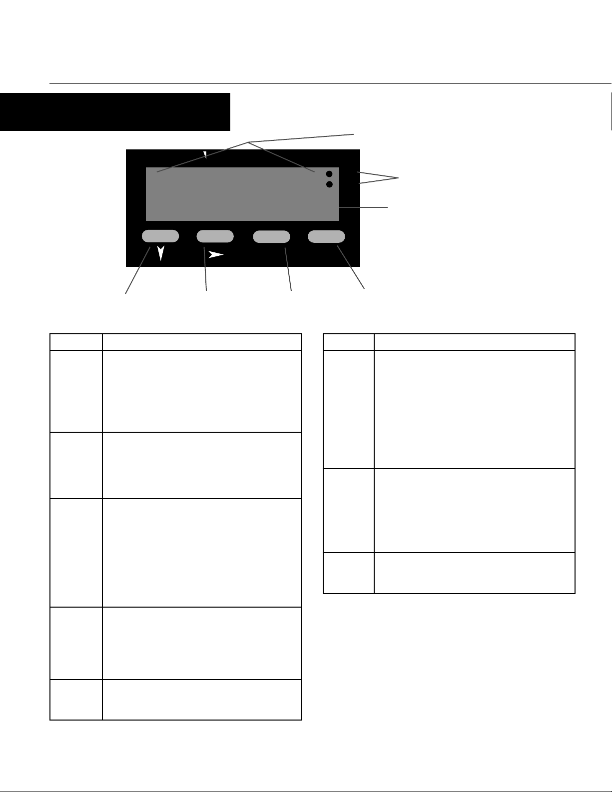
FRONT PANEL
VEEDER-ROOT
Primary Display
OP1
OP2
Output Indicators
82345
PGM
H
RST
Down Key Scroll Key Program Key Reset Key
Key Functions
Key
Down In Operation Mode: Used in edit operation to decrement
the digit highlighted by the Scroll key.
In Program Mode: Used in Edit Operation to decrement
the digit highlighted by the Scroll key, if the setting is
a numerical value, or present the next in the series of
choices for that parameter.
Scroll
Program In Operation Mode: Used to move between the position
In All modes: Moves the unit into Edit Operation,
which is indicated by the left most digit flashing.
Successive presses of the key are used to move to the
digit to be edited. Wrap around will occur from least
significant digit to most significant digit.
display & the alarms and to enter an edited alarm
value. Holding the key down for 3 seconds will cause
the unit to enter Program Mode.
In Program Mode: Used to move from one parameter to
the next and enter the edited parameter values.
Holding the key down for 3 seconds will cause the
unit to return to Operation Mode.
Function
Display
Primary In Operation Mode: Default display is the position.
Secondary In Operation Mode: Indicates alphabetically if one of
Output
Indicators
Secondary Display
Display Functions
Function
Can be scrolled using the program key to display the
alarm values. If the "Help" function is enabled, this
display will first show the parameter description for 3
seconds (see page 5 for example).
In Program Mode: Displays the value or selection for
the current parameter. If the "Help" function is
enabled, this display will first show the parameter
description for 3 seconds (see page 6 for example).
the alarms is being viewed on the primary display.
This display is blank when Position is being shown.
In Program Mode: Provides a 1 digit alpha or numeric
character to indicate which parameter value is being
shown on the primary display.
In All Modes: OP1 illuminates when the High Alarm
Value is reached. OP2 illuminates when the Low Alarm
Value is reached.
Reset In Operation Mode: Resets the position display to zero
(under Reset Value in Program Mode). This button can
be disabled via the "Front Panel Reset Enable"
parameter in Program Mode.
In All modes: No function.
Down &
Scroll
together
4
In All modes: Will abort an Edit Operation and return
the parameter to its previous value.
Page 5

OPERATION
OPERATION MODE
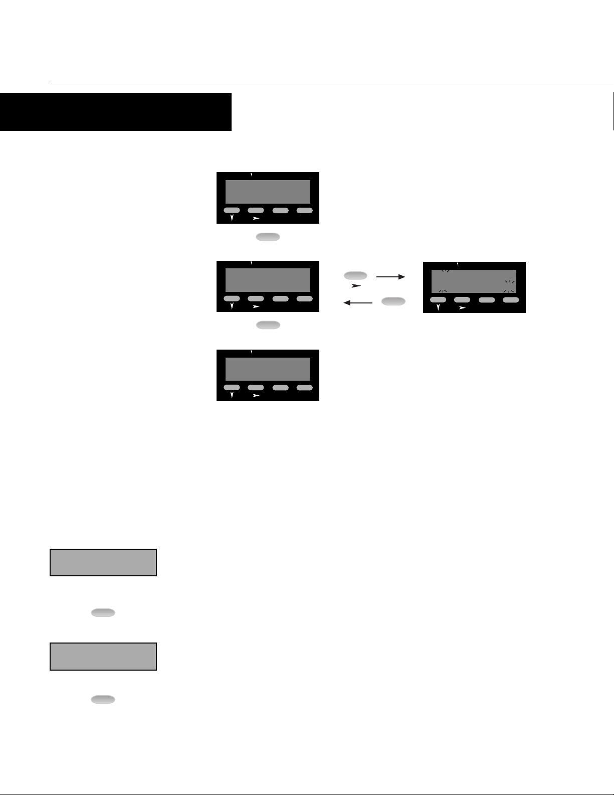
CHANGING A PRESET VALUE
VEEDER-ROOT
Default display is the position value.
OP1
OP2
23456
RST
PGM
PGM
VEEDER-ROOT
PoSn
PGM
RST
Pressing the Program Key will cause the
OP1
OP2
display description to appear on the
main display.* If there is no key activity
for 3 seconds, the primary display will
switch back to the position value.
VEEDER-ROOT
PGM
VEEDER-ROOT
33567
PGM
H34567
RST
H
RST
Use the Scroll Key to move from left to
OP1
OP2
right and highlight the digit that needs
to be changed. Wrap around will occur
from the least significant to the most
significant digit.
Use the Down Key to decrement the
OP1
OP2
digit until the desired value appears.
The display will wrap around from 0 to
9.
PGM
VEEDER-ROOT
Hi AL
PGM
VEEDER-ROOT
34567
PGM
RST
H
RST
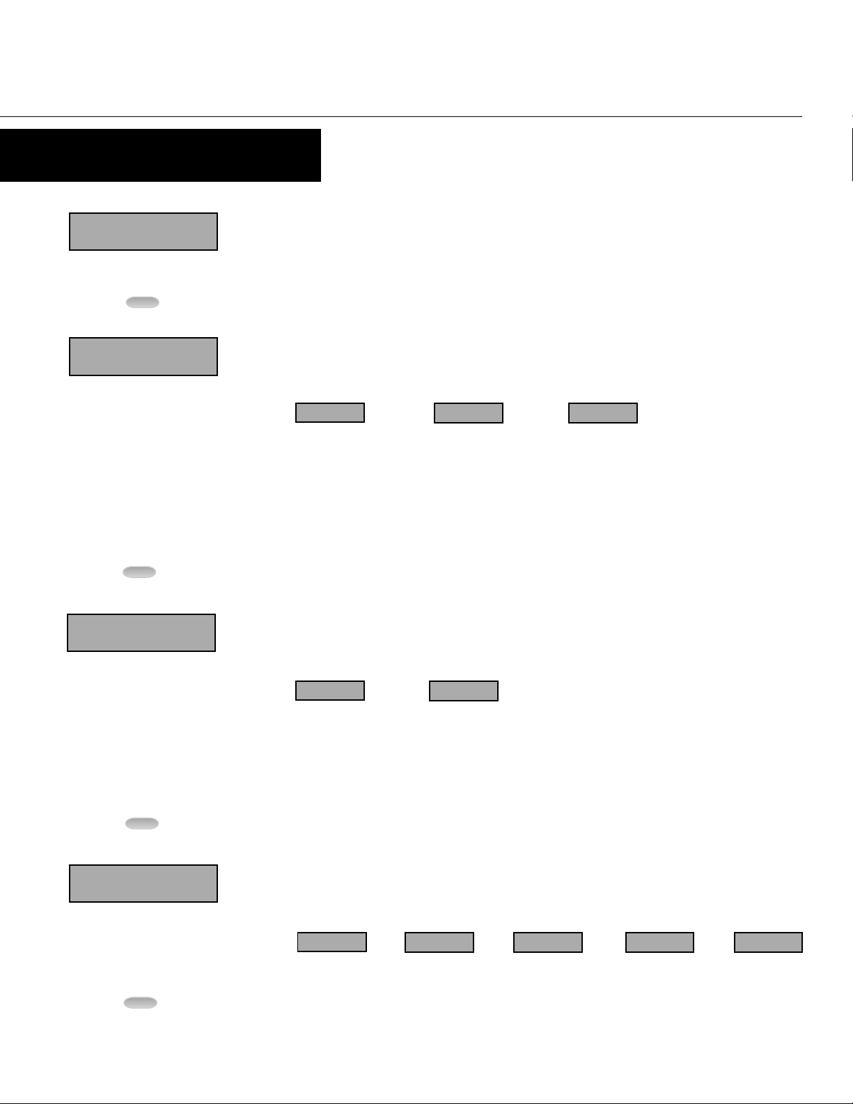
Continued pressing of the Program Key
OP1
OP2
will scroll to the Alarms. (See Parameter
Sequence below.) The full parameter
description will appear on the main
display.*
To change a Parameter value, press the
OP1
OP2
Scroll Key. If there was no key activity
for 3 seconds, the Alarm value will
appear (one digit description shown on
secondary display); however, press the
Scroll Key in order to edit. The unit will
now be in Edit Operation as signified by
the most significant digit flashing.**
PARAMETER SEQUENCE
Position
PoSn
Function: Displays position value
Range: -19999 to 99999
PGM
High Alarm Value
Hi
AL
H
Function: Defines the position value at or
above which Alarm 1 will activate
Adjustment Range: -19999 to 99999
Default Value: 1000
PGM
PGM
Hi AL
VEEDER-ROOT
PGM
PGM
RST
After the desired digits have been
OP1
OP2
changed, press the Program Key to enter
the new value. The new value will
appear on the main display without any
flashing digits. Press the Progam Key
again and the parameter description will
appear on the main display.
* Parameter descriptions will not
appear on the primary display if the
"Help" function has been disabled.
** Edit Operation cannot be
accessed if the Preset Lock has
been enabled in Program Mode.
Low Alarm Value
Lo
AL
L
Function: Defines the position value at
or below which Alarm 2 will activate
Adjustment Range: -19999 to 99999
Default V alue: 10
5
Page 6
PROGRAMMING
PROGRAM MODE
ENTERING PROGRAM MODE AND BASIC OPERATION
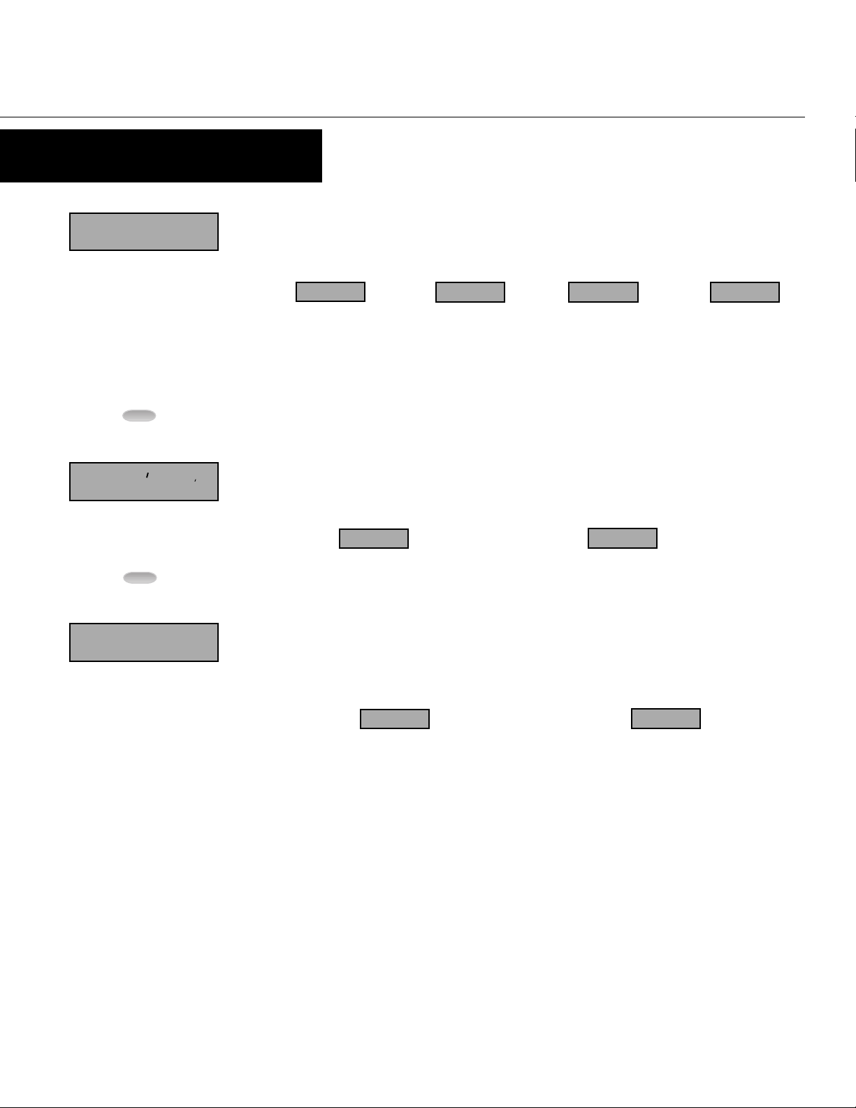
The Program Mode can be accessed from the
VEEDER-ROOT
Operation Mode by holding the Program Key
for 3 seconds.
The name of the first parameter will appear
23456
VEEDER-ROOT
on the primary display.*
CAL
Successive presses of the Program Key will
scroll the display through the remaining
parameters in the Program Mode. To exit
Program Mode, hold the Program Key for 3
seconds.
* Parameter names will not appear on the
main display if the "Help" function has been
disabled in Program Mode.
VEEDER-ROOT
dEc P
PGM
for 3 seconds
PGM
PGM
PGM
PGM
RST
RST
RST
OP1
OP2
no key activity
OP1
OP2
for 3 secs. or
PGM
Edit Operation
VEEDER-ROOT
1..0000
PGM
C
RST
OP1
OP2
Pressing the Scroll Key or no key activity for
3 seconds will display the value for that
parameter. The secondary display will
OP1
OP2
indicate the one digit identifier for the
parameter. The digit in the secondary
display will flash to indicate the unit is in
Program Mode. If the Scroll Key was
pressed (instead of waiting 3 seconds), the
unit is in Edit Operation, as indicated by the
MSD flashing. If there had been no key
activity for 3 seconds, press the scroll key to
enter Edit Operation (MSD flashing). Use
the scroll and edit buttons to change the
value as in Operation Mode, described on
page 5. Press the Program Key to enter any
changes.
PARAMETER SEQUENCE
P
C
d
CAL
PGM
dEc
PGM
6
Calibration Factor
Function: Used to scale the input into engineering units by multiplying this value by the number of pulses
received
Adjustment Range: 0.0001 to 9.9999
Default V alue: 1.0000
Decimal Position
Function: Set the decimal point position for the position and alarm displays
Adjustment Range: 0 to 0.0000
Default Value: 0
Page 7
PROGRAMMING
PROGRAM MODE Continued
Reset Value
rESEt
PGM
SPEEd
S
F
Function: Defines a "home position by selecting a value other than zero or another value within the displayed
range of the device to which the counter can reset
Adjustment Range: -19999 to 99999
Default Value: 0
Filter Speed
Function: Enables the debounce filter of the counter to properly match the application
Adjustment Range:
rS
PGM
PGM
En
20 200
20: The unit will accept
up to 20 pulses per
second. Generally used
with contact inputs to
eliminate false counts
caused by contact bounce
Default Value: 10000
Front Panel Reset Enable
r
Function: Determines whether the Front Panel Reset key can be used to reset the position value
Adjustment Range:
En
Enable: The position
value can be reset while
being viewed in Operation
Mode by pressing the
Front Panel Reset Key
Default V alue: Enable
200: The unit will accept
up to 200 pulses per
second. Generally used
for higher speed contact
inputs or to filter noise
on electronic signals in
low speed applications
diS
Disabled: The Front
Panel Reset Key is
disabled and the position
value can only be reset
through the Remote
Reset Input
10000
10,000: The unit will
accept up to 10,000
pulses per second.
Generally used with high
speed electronic inputs
and encoders
rt
PGM
En
Retransmission Enable/Select
t
Function: Determines whether a voltage/current is an output, and if so, which range
Adjustment Range:
nonE
None 0-5 V olts 0-10 Volts 0-20 mA
Default V alue: None
0-5u
0-10u
0-20A
4-20A
4-20 mA
7
Page 8

PROGRAMMING
PROGRAM MODE Continued
rt
rt
Lo
PGM
Hi
PGM
Co<>S
PGM
Retransmission Scale Minimum
L
H
c
Function: Defines the lower end of the linear scale for the retransmission output by defining the value equated
to the minimum output signal - i.e. for a 4-20 mA output, this would be the value corresponding to 4 mA
Adjustment Range: -19999 to 99999
Default Value: 0
Retransmission Scale Maximum
Function: Defines the upper end of the linear scale for the retransmission output by defining the value equated
to the maximum output signal - i.e. for a 4-20 mA output, this would be the value corresponding to 20 mA
Adjustment Range: -19999 to 99999
Default V alue: 100
Serial Communication Enabled
Function: Activates the RS-485 communication option board
Adjustment Range:
nonE
None: No communication
board installed
Default V alue: If ordered from the factory with the RS-485 board, the default will be "fitted". If the board is
installed in the field, this parameter will need to be changed from its default of "none"
Fitted: A communication
board is installed in the
unit
(Appears only if a current/voltage is selected)
(Appears only if a current/voltage is selected)
Fit
Addr
PGM
bAud
PGM
8
Communication Address
A
b
Function: Defines the unique communication address of the unit
Adjustment Range: 1 to 99
Default Value: 1
Baud Rate
Function: Selects the serial communication speed
Adjustment Range:
Default V alue: 4800
(Appears only if communication board is installed and activated)
1200
1200 BPS 2400 BPS 4800 BPS 9600 BPS
(Appears only if communication board is installed and activated)
2400
4800
9600
Page 9
PROGRAMMING
PROGRAM MODE Continued
Display Color Change
Color
o
Function: Defines the color of the display
Adjustment Range:
PGM
Loc/
PGM
HELP
rEd
Red: The display will
always be red
Default V alue: Green to Red
Preset Lock
/
h
Function: Determines whether the Alarm Values can be changed via the front panel
Adjustment Range:
En
Enable: Alarm values are read only
Default Value: Disable
Help Prompt
Function: Determines whether the multi-character parameter name will appear on the main display for 3
seconds prior to the parameter value appearing
Adjustment Range:
GrEEn
Green: The display will
always be green
Gn_rd rd_Gn
Green to Red: The
display will be green prior
to the Alarm value being
reached. It will turn red
after the Alarm has been
reached
diS
Disabled: Alarm values can be viewed and
changed
Red to Green: The
display will be red prior to
the Alarm value being
reached. It will turn green
after the Alarm has been
reached
HLP
Help - Yes: Multi-character parameter descriptions
will appear on the primary display. The value
associated with that parameter will appear by
pressing the scroll key or waiting for 3 seconds
Default V alue: Help - Yes
Y
Help - No: Only the parameter values will appear on
the primary display. The parameter can be identified
by a single digit in the secondary display
HLP
N
9
Page 10

APPENDIX A
SPECIFICATIONS
Count Inputs
Type: Quadrature
Frequency: 5 kHz max.
Logic: Low < 2.0 VDC, High > 3.0, 30V max.
Impedance: 10 KΩ to common - Sourcing
4.7 KΩ to +Voltage - Sinking
Control Inputs
Type: Sinking, Edge Sensitive
Logic: Low < 2.0 VDC, High > 3.0
Impedance: 4.7 KΩ to +Voltage
Response Time: 25 ms
Function: Input 1: Remote Reset
Input 2: Security Lockout
Outputs
Solid State: NPN open collector, 30 VDC max, 100 mA max.
Relay: SPDT, 5A resistive @ 110VAC
Latency: 75 µ seconds, plus 8 ms for relay pull-in
Linear Outputs
Ranges: 0-20mA, 4-20mA, 0-10V, 2-10V, 0-5V, 1-5V
Accuracy: ±0.25% (mA at 250Ω, V at 2kΩ);
degrades linearly to ±0.5%
Resolution: 8 bits in 250ms (10 bits in 1s typ.)
Update: Approximately 4/s
Load Impedence: mA Ranges: 500Ω max.; V Ranges: 500Ω min.
Communication
Type: Serial asynchronous, UAR T to UART
Data For mat: Open ASCII: One start bit, even parity seven
Physical Layer: RS-485
Maximum Zones: 99
Baud Rate: Selectable from 9600, 4800, 2400, or 1200
Electrical
Supply Voltage: 90-264 VAC, 50/60 Hz, or 20-50 VAC/VDC
Power Consumption: 4 Watts
Access. Power Supply:9-15 (unregulated VDC), 125 mA max.
Display
Type: Red/Green, 7 segment LED, 5 digits primary
Height: 0.71" (18mm) primary display,
Annunciators: Output 1 & 2 status
Physical
Dimensions: 48mm x 96mm, 110mm deep
Mounting: Panel mount (mounting bracket supplied),
Ter minals: Screw type - combination head
Front Panel Rating: NEMA 4X/IEC IP65
Case Material: GE Lexan 940
Weight: 0.56 lbs.
data bits, one stop bit
display, single digit secondary display
0.3" (7mm) secondary display
45mm x 92mm cutout
Approvals
General: CE
EMC Susceptibility: Complies with EN50082-1: 1992,
EN50082-2: 1995
EMC Emissions: Complies with EN50081-1: 1992,
EN50081-2: 1994
Safety: Complies with EN61010-1: 1993
10
Environmental
Operating Temp.: 0° to 55° Celsius, 32° to 131° Fahrenheit
Storage Temp.: -20° to 80° Celsius, -4° to 176° Fahrenheit
Relative Humidity: 20% to 95% non-condensing
Page 11

GENERAL
NOTES
11
Page 12

GENERAL
Danaher Controls
ORDERING INFORMATION
C628 - 2
2nd Relay Option
0 None
1 2nd Relay
Linear Output
Option
0 None
3 Linear Output
Serial Communication
Option
0 None
5 RS-485
WARRANTY
Standard products manufactured by the Company are warranted to be
free from defects in workmanship and material for a period of one year
from the date of shipment, and products which are defective in
workmanship or material will be repaired or replaced, at the option of the
Company, at no charge to the Buyer . Final determination as to whether a
product is actually defective rests with the Company. The obligation of
the Company hereunder shall be limited solely to repair and replacement
of products that fall within the foregoing limitations, and shall be
conditioned upon receipt by the Company of written notice of any alleged
defects or deficiency promptly after discovery within the warranty period,
and in the case of components or units purchased by the Company, the
obligation of the Company shall not exceed the settlement that the
Company is able to obtain from the supplier thereof. No products shall
be returned to the Company without its prior consent. Products which
the Company consents to have returned shall be shipped F.O.B. the
Company's factory. The Company cannot assume responsibility or
accept invoices for unauthorized repairs to its components, even though
defective. The life of the products of the Company depends, to a large
extent, upon the type of usage thereof, and THE COMPANY MAKES NO
WARRANTY AS TO FITNESS OF ITS PRODUCTS FOR SPECIFIC
APPLICATIONS BY THE BUYER NOR AS TO PERIOD OF SERVICE
UNLESS THE COMPANY SPECIFICALLY AGREES OTHERWISE IN
WRITING AFTER THE PROPOSED USAGE HAS BEEN MADE KNOWN TO
IT.
THE FOREGOING WARRANTY IS EXCLUSIVE AND IN LIEU OF ALL
OTHER WARRANTIES EXPRESSED OR IMPLIED, INCLUDING, BUT NOT
LIMITED TO ANY WARRANTY OF MERCHANTABILITY OR OF FITNESS
FOR A PARTICULAR PURPOSE.
Power Supply
0 90-264 VAC
2 20-50 VAC/VDC
Additional outputs and options can be
field installed through plug-in boards
which can be ordered separately.
Description Part #
Relay Board T50-001
DC Linear Board T50-003
RS-485 Comm. Board T50-005
Printed in U.S.A.
702138-0002
March 1998
Revision none
12
1675 Delany Road
Gurnee, IL 60031–1282
Phone: 847.662.2666
Fax: 847.662.6633
 Loading...