

Page 1
Introduction
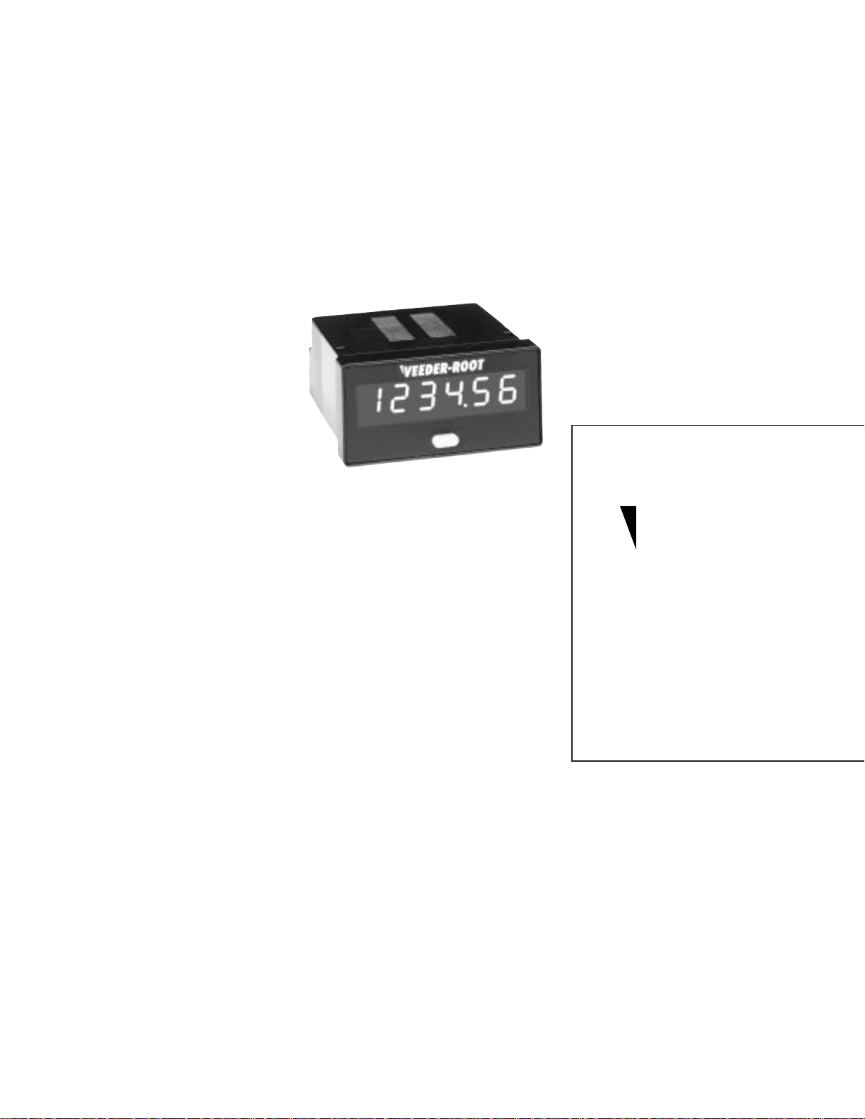
Your Veeder-Root brand Series C342 panel instrument is powered by an external 12 - 24 VDC supply,
features an 6 digit LED display, and is housed in a ultra compact 1/32 DIN package.
This model has been configured at the factory to perform one of the following functions: Count
Totalizer, Position Indicator, Time Totalizer (Hours:Minutes:Seconds), Time Totalizer (Hours, 1/100
resolution), Tachometer or a PLC message display. There are also several programmable features that
let you select a sinking or sourcing input, a count input filtering speed, and whether or not to enable
the front panel reset.
The following pages of the manual will provide information on proper panel mounting of the device,
terminal layout and wiring instructions, directions on how to access and set the field programmable
features, as well as an overview of the basic operating functions of the unit. Also included are the key
product specification, warranty
procedures and ordering information
should you require additional units.
Models Covered in this Manual
C342-0464 Totalizer: Accumulates
and displays counted pulses. Total can
be reset via front panel button (may be
disabled) or remote reset terminals.
Model available with factory
programmed setting of Setpoint,
Prescale Value, and/or Decimal Position.
C342 -8562 Position Indicator: The
instrument will count in a bi-directional
mode based on the quadrature input from an
encoder. Display range is -99999 to 99999.
C342-1464 Time Totalizer: Accumulates
time in the format Hours:Minutes:Seconds.
Can be reset via front panel button (may be
disabled) or remote reset terminals. Model
available with factory programmed preset
output.
Features
•
Available models include count and time
totalization, rate metering, position
indication and a PLC message display
•
Bright 6 digit LED display provides easy to
read process values
•
Compact 1/32 DIN bezel and 60mm
behind the panel depth save panel space
•
Powered by 12 - 24 VDC, with nonvolitale
RAM for retention of process value and
settings
•
Field programmable for NPN or PNP
signals and for hi-speed (7.5 kHz) or low
speed (30 Hz) filtering
•
Factory programmable features: Setpoint,
Scale Value, Decimal Position, Text
Message
•
IEC IP65 rated front panel for use in
washdown environments
C342-2464 Time Totalizer:
Accumulates time in hours with 1/100
resolution. Can be reset via front panel
button (may be disabled) or remote reset
terminals. Model available with factory
programmed preset output.
C342-3464 Tachometer: Pulses are
sampled for a 6 second period then
displayed as a rate value in units per
minute. A Display Hold input can freeze
the current reading. Model available with
factory programmed setting of Setpoint,
and/or Decimal Position.
C342-4562 Message Display: The
instrument will display alpahumeric
messages based on a digital input from a
PLC Please refer to separate insruction
sheet which provides specific information
on how to interface to a PLC. Model
available with factory programmed Text
Message.
Index
Overview
Installation page 2
Terminal Connections page 2
Setup
Front Panel Operation page 3
Programming page 3
General
Specifications page 4
Ordering Information page 4
Warranty page 4
Technical Manual
702085-0001
Veeder-Root
Series C342
DC Powered
LED Display
brand
1
Page 2
OVERVIEW
1 2 3 4 5 6 7 8
1 2 3 4 5 6 7 8
1 2 3 4 5 6 7 8
1 2 3 4 5 6 7 8
INSTALLATION
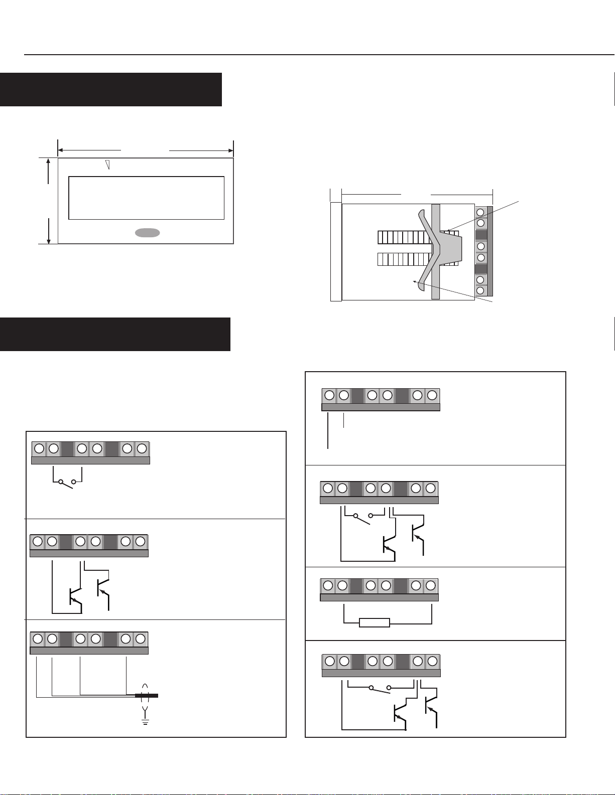
Dimensions
48 mm
VEEDER-ROOT
24
mm
123456
Recommended Panel Cutout: 22mm (±0.3mm) X 45mm (±0.6mm)
Panel Mounting
Make the recommended panel cutout. Place the included gasket
over the rear of the unit and place the unit in the panel cutout.
Slide the panel mount bracket into place over the unit's rear
allowing the bracket tabs to engage the grooves on the case.
Continue to push forward until the bracket arm fits snugly
against the panel.
8
mm
mm
60
Bracket Arm
Mounting
Grooves
REAR TERMINAL CONNECTIONS
Wiring
Insert wire into the appropriate openings as pictured in the drawing
below. Turn the screws, located on the rear of the terminal block to
tighten the clamp and secure the wire.
1 2 3 4 5 6 7 8
Contact
1 2 3 4 5 6 7 8
PNP
NPN
+
1 2 3 4 5 6 7 8
12 VDC
Common
Channel A
Note: Counting reletive to the encoder shaft
rotation can be reversed by swaping Channel A
and Channel B connections
Signal Input (from switch): Contact closure signals are accumulated for count and tachometer
versions. For timer versions the
timer runs when contact is closed.
See "Programming to select low
speed, NPN mode.
Signal Input (transistor): Signal pulses are accumulated for
count and tachometer versions.
For timer versions, timer runs
when signal is present. See
"Programming" for selection of
PNP or NPN signal
Quadrature Input (Encoder):
For bi-directional counting
connect corresponding encoder outputs to channel
A & B input terminals. The
Channel B
eccoder shield wire should be
connected to earth ground at
the counter.
– (Common)
+ (12 to 24 VDC)
Contact
–
10mA DC Maximum
Load
Contact
NPN
Power Wiring: Connect to 12
- 24 VDC (+20%/-10%) voltage source. Power requirement is 5 mA, Maximum
Remote Reset: the displayed
value will be reset. Signal input is ignored when the Reset
PNP
+
is active. For tachometer versions, this input is not used.
Solid State Output: When the
factory programmed preset
value is reached a PNP output
will be triggered. The output
+
will stay active until a reset
signal is received.
Gate Input: all incoming signals will be ingnored and the
present display value will be
held. For Position Indicator
versions, this input is not used.
NPN
PNP
+
2
Page 3

SETUP
OPERATION
VEEDER-ROOT
Front Panel Reset
On Time or Count models, used to
12345678
reset the Process Value Display.
May be disabled through the
keylock input. Also used to perform
Programming mode functions
Your C342 has been configured at the factory to perform one of the following functions:
C342-0562 Totalizer: The instrument will accumulate and display
the pulses received on the count input terminals (2 & 4). Count
capacity is 8 digits:
reset terminals (2 & 5) or the front panel.
C342 -8562 Position Indicator: The instrument will count in a bidirectional mode based on the quadrature input from an encoder
(terminals 2,5 & 7). Display range is -99999 to 99999.
C342-1562 Time Totalizer #1: The instrument will accumulate time
when the input signal (terminals 2 & 4) is active. The time will be
displayed in the format:
reset via the remote reset terminals (2 & 5) or the front panel.
123456
99:59:59
The total can be reset via the remote
Hours:Minutes:Seconds
123456
C342-2562 Time Totalizer #2: The instrument will accumulate time
when the input signal (terminals 2 & 4) are active. The time will be
displayed in hours with 1/100 resolution
reset via the remote input terminals (2 & 5) or the front panel.
C342-3562 Tachometer: Pulses received on the input terminals (2
& 3) are sampled for a 6 second period then displayed as a rate
value in units per minute:
(terminals 2 & 7) will freeze the current reading.
C342-4562 Message Display: The instrument will display
and can be
alpahumeric messages based on a digital input from a PLC Please
refer to separate insruction sheet which provides specific
information on how to interface to a PLC.
Process Value Display
Displays the count, time or rate
value based upon the model
999990
9999.99
A Display Hold function
and can be
PROGRAMMING
L0 NPN
L0 PNP
1
H1
loc
During Power-up
NPNH
PNP
Hold for 2 seconds
To access Input Configuration Parameters:
• Enter the Program Mode by holding the Front Panel Reset (FPR) key during power-up
• Scroll throuugh the 4 input configuration choices by brief press and release of the FPR key
• When the desired choice appears, hold down the the FRP key for seconds to select it
• Scroll between the two Front Panel Enable choices by brief press and release of the FPR key.
Hold the FPR key for 2 sconds to select the desired choice and return to Operating Mode
Note: The NPN/PNP selection applies to the Signal, Reset, and Hold inputs
Low Speed NPN Input: Configures the unit to accept a sinking or dry contact input and sets a filtering
speed of 30 Hz
Low Speed PNP Input: Configures the unit to accept a sourcing input and sets a filtering speed of 30 Hz
High Speed NPN Input: Configures the unit to accept a sinking or dry contact input of up to 7.5 kHz
Note: This choice will not appear for Time Totalizer models
High Speed PNP Input: Configures the unit to accept a sourcing input of up to 7.5 kHz
Front Panel Reset Locked: Pressing the front panel reset key during operation will not reset the
accumualted count/time value
unloc
Hold for 2 seconds to return to Operating Mode
Front Panel Reset Unlocked: Pressing the front panel reset key during operation will cause the
accumualted count/time value to be reset.
3
Page 4

SPECIFICATIONS
GENERAL
Count /Time Input:
Count Input: NPN or PNP Signal field selectable
Count Speed: 30 Hz or 7.5 kHz max
Logic: Low < 0.7 VDC, High > 5 VDC
Minimum Pulse Width: 70 µsecond
Maximum Input: 30 VDC
Quadrature Input (C342-8562 only):
Type: Line driver or square wave pulse (A leading B for up
counting)
Count Speed: 2 kHz
Physical:
Dimensions: 24mm x 48mm, 32mm deep
Mounting: Panel Mount (mounting bracket supplied)
22mm (+ 0.3mm) x 45mm (+ 0.6mm) panel cutout
Maximum Panel Thickness: 26mm
Connections: 6 screw terminals
Weight: Approximately 2.25 ounces
Front Panel Rating: IEC IP65
ORDERING INFORMATION
Part # Description
C342-0562 Count Totalizer
C342-0562-A As above with factory programmed value*
C342-1562 Timer (H:M:S)
C342-1562-A As above with factory programmed value*
C342-3464 Tachometer
WARRANTY
Reset Input:
Type: NPN Signal, Contact Closure
Minimum Pulse Width: 15 ms
Gate Input:
Type: NPN Signal, Contact Closure
Output: (C342-0562, C342-1562, C342-2562):
Type: PNP transistor
Voltage/Curent: Supply less 2 Volt drop, 10 mA max
Operation:
Power Supply: 12 - 24 VDC (+20%/-10%)
Power Consumption: <150 mA
Display Type: 6 digit LED
Display Height: 7.6 mm
Data Retention: Non volatile RAM > 10 years
Factory Programmable Settings: Setpoint, Prescale Value,
Decimal Position, Text Message
Operating Temperature: -10°C to 50°C
Storage Temperature: -20°C to 60°C
Approvals: CE Mark
Part # Description
C342-2562 Timer (Hundreths of Hours)
C342-2562-A As above with factory programmed value*
C342-3562 Tachometer
C342-4562 Message Display
C342-8562 Position Indicator
* Possible Factory Programmable Settings: Setpoint, Prescale
Value, Decimal Position, Text Message. Specifcy the setting
and value when placing an order. (Ex: Setpoint = 4567)
Standard products manufactured by the Company are warranted
to be free from defects in workmanship and material for a period
of one year from the date of shipment, and products which are
defective in workmanship or material will be repaired or replaced,
at the option of the Company, at no charge to the Buyer. Final
determination as to whether a product is actually defective rests
with the Company. The obligation of the Company hereunder
shall be limited solely to repair and replacement of products that
fall within the foregoing limitations, and shall be conditioned
upon receipt by the Company of written notice of any alleged
defects or deficiency promptly after discovery within the warranty
period, and in the case of components or units purchased by the
Company, the obligation of the Company shall not exceed the
settlement that the Company is able to obtain from the supplier
thereof. No products shall be returned to the Company without its
Printed in U.S.A.
#702085-0001
4
February 13, 1997
Revision none
prior consent. Products which the Company consents to have returned
shall be shipped F.O.B. the Company's factory. The Company cannot
assume responsibility or accept invoices for unauthorized repairs to its
components, even though defective. The life of the products of the
Company depends, to a large extent, upon the type of usage thereof,
and THE COMPANY MAKES NO WARRANTY AS TO FITNESS OF ITS
PRODUCTS FOR SPECIFIC APPLICATIONS BY THE BUYER NOR AS
TO PERIOD OF SERVICE UNLESS THE COMPANY SPECIFICALLY
AGREES OTHERWISE IN WRITING AFTER THE PROPOSED USAGE
HAS BEEN MADE KNOWN TO IT.
THE FOREGOING WARRANTY IS EXCLUSIVE AND IN LIEU OF ALL
OTHER WARRANTIES EXPRESSED OR IMPLIED, INCLUDING, BUT
NOT LIMITED TO ANY WARRANTY OF MERCHANTABILITY OR OF
FITNESS FOR A PARTICULAR PURPOSE.
Danaher Controls
1675 N. Delany Road
Gurnee, IL 60031–1282
Phone: 847.662.2666
Fax: 847.662.6633
 Loading...