

Page 1
Introduction
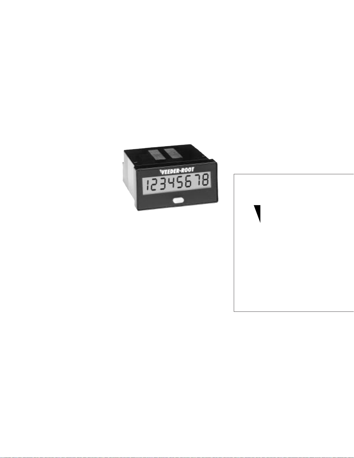
Your Veeder-Root brand Series C342 panel instrument is powered by an external 12 - 24
VDC supply, features an 8 digit LCD display, and is housed in a ultra compact 1/32 DIN
package.
This model has been configured at the factory to perform one of the following functions:
Count Totalizer, Time Totalizer (Hours:Minutes:Seconds), Time Totalizer (Hours, 1/100
resolution), Tachometer or a PLC message display. There are also several programmable
features that let you select a sinking or sourcing input, a count input filtering speed, and
whether or not to enable the front panel reset.
The following pages of the manual will provide information on proper panel mounting of the
device, terminal layout and wiring instructions, directions on how to access and set the field
programmable features, as well as an overview of the basic operating functions of the unit.
Also included are the key product specification, warranty procedures and ordering
information should you require
additional units.
Models Covered in this Manual
C342-0462 Totalizer: Accumulates and
displays counted pulses. Total can be
reset via front panel button (may be
disabled) or remote reset terminals.
C342-1462 Time Totalizer: Accumulates
time in Hours:Minutes:Seconds format.
Can be reset via front panel button
(may be disabled) or remote reset
terminals.
C342-2462 Time Totalizer: Accumulates time in
hours with 1/100 resolution. Can be reset via
front panel button (may be disabled) or
remote reset terminals.
C342-3462 Tachometer: Pulses are sampled for a
6 second period then displayed as a rate
value in units per minute. A Display Hold
input can freeze the current reading.
C342-4462 Message Display: Please refer to
the additional instruction sheet which
provides specific information on how to
interface to a PLC.
Technical Manual
702082-0001
Veeder-Root
Series C342
DC Powered
LCD Display
brand
Index
•
Available models include count and time
totalization and rate metering
•
Crisp 8 digit LCD display provides easy to
read process values
•
Compact 1/32 DIN bezel and 32mm
behind the panel depth save panel space
•
Power by 12 - 24 VDC, with nonvolatile
RAM for retention of process value and
settings
•
Field programmable for NPN or PNP
signals and for hi-speed (7.5 kHz) or low
speed (30 Hz) filtering
•
IEC IP65 rated front panel for use in
washdown environments
Overview
Installation page 2
Terminal Connections page 2
Setup
Front Panel Operation page 3
Programming page 3
General
Specifications page 4
Ordering Information page 4
Warranty page 4
Page 2
REAR TERMINAL CONNECTIONS
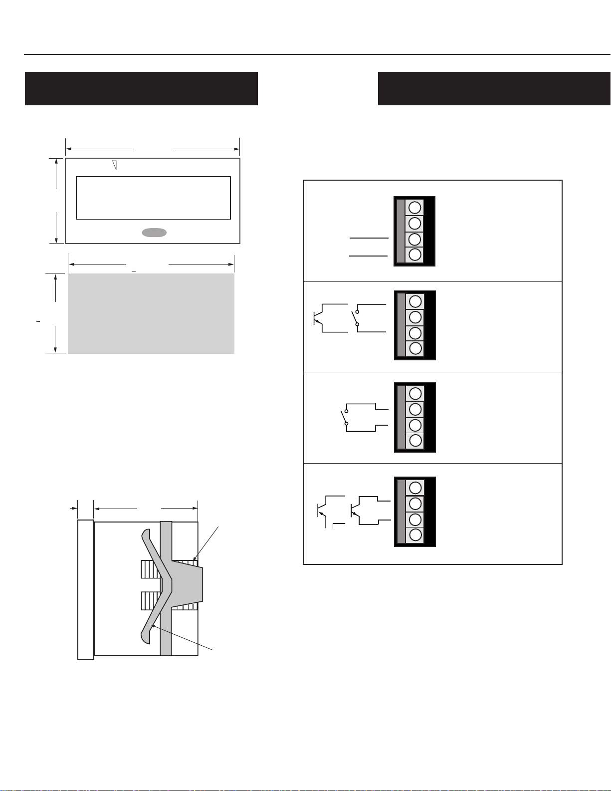
Dimensions
Wiring
Insert wire into the appropriate openings as pictured in the drawing
48 mm
below. Turn the screws, located on the left side of the terminal block
to tighten the clamp and secure the wire.
VEEDER-ROOT
24
mm
12345678
– (Common)
45 mm
+0.6 mm
22 mm
+0.3mm
Panel Mounting
Make a panel cutout per the recommended opening illustrated by the
figure above. Place the included gasket over the rear of the unit and
place the unit in the panel cutout. Slide the panel mount bracket into
place over the unit's rear allowing the bracket tabs to engage the
grooves on the case. Continue to push forward until the bracket arm
fits snugly against the panel.
+ (12 to 24 VDC)
NPN
Contact
Contact
Power Wiring: Connect to
1
12 - 24 VDC (+20%/-10%)
voltage source. Power require-
2
ment is 5 mA, Maximum.
3
4
Remote Reset: the displayed
1
1
value will be reset for counting or timing models. Count
2
2
Input is ignored when the Re-
3
set is active.
3
version
4
4
1
1
2
2
3
3
4
4
, this terminal serves
as a display hold input.
Signal Input (from switch):
Contact closure signals are
accumulated for count and tachometer versions.
versions
contact is closed. See "Programming" to select Low
speed, NPN mode.
, timer runs when
On tachometer
For timer
8
mm
Top View
32
mm
Mounting
Grooves
Bracket Arm
PNP
Signal Input (transistor):
1
Signal pulses are accumulated
1
NPN
+
–
for count and tachometer ver-
2
2
3
3
4
4
For timer versions
sions.
timer runs when signal is
present. See "Programming"
for selection of PNP or NPN
signal.
,
1
2
3
4
Page 3

VEEDER-ROOT
On Time or Count models, used to
reset the Process Value Display.
May be disabled through the
programming procedure, below.
Also used in selection of
Programming mode functions
Dependant on model, your C342 will perform one of the following functions:
C342-0462 Totalizer: The instrument will accumulate and
display the pulses received on the count input terminals (2 & 3).
Count capacity is 8 digits:
via the remote reset terminals (1 & 3) or the front panel.
C342-1462 Time Totalizer: The instrument will accumulate
time when the input signal (terminals 2 & 3) is active. The time
will be displayed in the format:
Hours:Minutes:Seconds and can be reset via the remote reset
terminals (1 & 3) or the front panel.
C342-4462 Message Display: Please refer to separate instruction sheet which provides specific information on how to interface to a PLC.
12345678
9999:59:59
. The total can be reset
12345678
C342-2462 Time Totalizer: The instrument will accumulate time
when the input signal (terminals 2 & 3) are active. The time will be
displayed in hours with 1/100 resolution
be reset via the remote input terminals (1 & 3) or the front panel.
C342-3462 Tachometer: Pulses received on the input
terminals (2 & 3) are sampled for a 6 second period then
displayed as a rate value in units per minute:
Display Hold function (terminals 1 & 3) will freeze the current
reading.
• Enter the Program Mode by holding the Front Panel Reset (FPR) key during power-up
• Scroll through the four input configuration choices by brief press and release of the FPR key
• When the desired choice appears, hold down the FPR for 2 seconds to select it
• Scroll between the two Front Panel Reset Enable choices by brief press and release of the FPR
key. Hold the FPR key for 2 seconds to select the desired choice and return to the
Operating Mode
999999.99
999990
and can
. A
When desired input mode is displayed, hold for 2 seconds
loc
unloc
Hold for 2 seconds to return to Operating Mode
Low Speed PNP Input: Configures the unit to accept a sourcing input and sets a filtering speed of 30 Hz
Note: This choice will not appear for Time Totalizer models
Front Panel Reset Locked: Pressing the front panel reset key during operation will not reset the
accumulated count/time value
Front Panel Reset Unlocked: Pressing the front panel reset key during operation will cause the
accumulated count/time value to be reset.
Page 4

Count/Time Input:
Count Input: NPN or PNP Signal field selectable
Count Speed: 30 Hz or 7.5 kHz max
Reset Input:
Type: NPN Signal, Contact Closure
Minimum Pulse Width: 15 ms
Logic: Low < 0.7 VDC, High > 5.0 VDC
Minimum Pulse Width: 70 µsecond
Maximum Input: 30 VDC
Physical:
Dimensions: 24mm x 48mm, 32mm deep
Operation:
Power Supply: 12 - 24 VDC (+20%/-10%), 5 mA, Max.
Display Type: 8 digit LCD
Display Height: 7 mm
Data Retention: Non volatile RAM, >10 years
Operating Temperature: -10°C to 50°C
Mounting: Panel Mount (mounting bracket supplied)
22mm (+ 0.3mm) x 45mm (+ 0.6mm) panel cutout
Maximum Panel Thickness: 14mm
Connections: 4 screw terminals
Weight: Approximately 1 ounce
Front Panel Rating: IEC IP65
Storage Temperature: -20°C to 60°C
Approvals: CE
Part # Description
C342-0462 Count Totalizer
C342-1462 Timer (H:M:S)
C342-2462 Timer (Hundreths of Hours)
C342-3462 Tachometer
C342-4462 Message Display
Printed in U.S.A.
#702082-0001
February 13, 1997
Revision none
Danaher Controls
1675 N. Delany Road
Gurnee, IL 60031–1282
Phone: 847.662.2666
Fax: 847.662.6633
 Loading...