

Page 1
T^
VEEDER-ROOT
INSTALLATION,
OPERATION
AND
SERVICE
INSTRUCTIONS
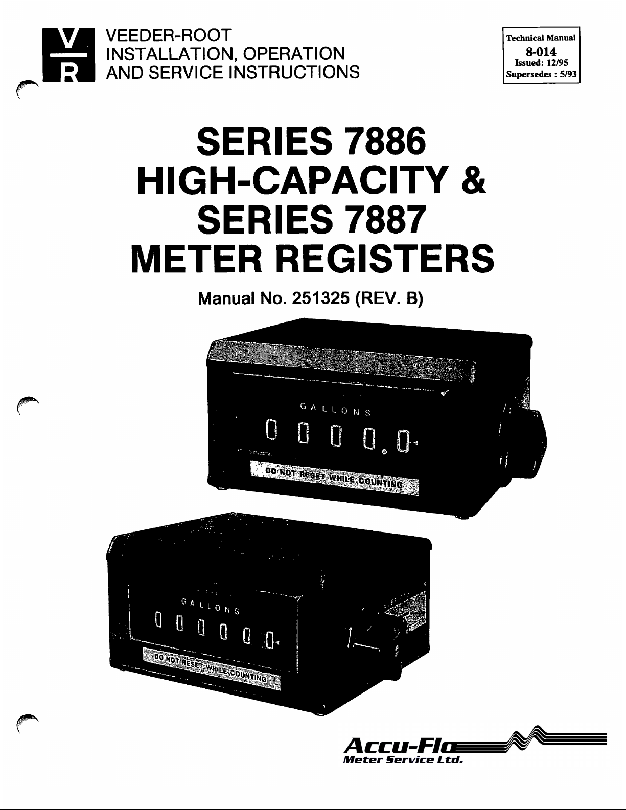
SERIES
7886
HIGH-CAPACITY
&
SERIES
7887
METER
REGISTERS
Manual
No.
251325
(REV.
B)
Technical
Manual
8-014
Issued:
12/95
Supersedes
:
5/93
VEEDER-ROOT
Petroleum
Products
Page 2
Installation,
Operation
and
Service
Manual
Series
7886
High-Capacity
&
7887
Meter
Registers
TABLE
OF
CONTENTS
SECTION
1.
INTRODUCTION
A.
General
1
SECTION
2.
SERIES
7887
DESCRIPTION
A.
General
1
B.
Specifications
2
SECTION
3.
SERIES
7886
DESCRIPTION
A.
General
3
B.
Specifications
3
SECTION
4.
PERIODIC
INSPECTION
A.
General
5
B.
Disassembly
Prior
to
Cleaning
5
C.
Cleaning
5
D.
Inspection
5
E.
Lubrication
5
F.
Troubleshooting
7
SECTION
5.
DISASSEMBLY
AND
ASSEMBLY
A.
General
8
B.
Removal
of
Major
Groups
8
C.
Individual
Parts
Replacement
10
D.
Installation
of
Major
Groups
10
E.
Final
Checks
and
Adjustments
15
F.
Operational
Check
16
SECTION
6.
DAMAGE
CLAIMS
AND
WARRANTY
A.
Damage
Claims
16
B.
Return
Shipping
16
C.
Warranty
and
Conditions
16
Page 3
Installation,
Operation
and
Service
Manual
Series
7886
High-Capacity
&
7887
Meter
Registers
SECTION
1.
INTRODUCTION
A.
GENERAL.
These
instructions
are
for
servicing
the
Series
7886
High-Capacity
and
Series
7887
Meter
Registers
designed
and
manufactured
by
the
Veeder-Root
Company,
6th
Avenue
at
Burns
Crossing.
P.O.
Box
1673,
Altoona,
PA
16603.
Phone:
(814)
695-4476.
When a vertical
bar | appears
adjacent
to
text
or
illus
trations,
information
has
been
added
or
changed
at
the
last
issue date.
Note:
Consult
Veeder-Root
on
any
unusual
application,
installation
or
possible
modification
of
this
basic
design.
Every
Meter
Register
is
thoroughly
tested
at
the
Veeder-Root
factory
and
by
the
meter
manufacturer
when
installed
on
the
meter.
However,
like
any
precision
mechanism,
it
requires
periodic
care
to
ensure
maximum
service.
This
manual
is
for
use
in
areas
where
factory
rebuilding
facilities
and
adequate
exchange
stocks
are
not
readily
accessible.
Where
manufacturer's
replacement
stocks
are
available,
it
is
important
that
no
attempt
be
made
to
repair
any
meter
register
defective
within
the
terms
of
the
warranty
as
by
doing
so,
the
warranty
is
void
and
the
user
is
deprived
of
the
protection
provided
by
the
warranty.
It
is
recommended
that,
when
possible,
meter
registers
be
replaced
and
the
defective
unit
returned
to
the
meter
manufacturer.
Note:
See
Section 6 for
complete
Damage
Claims
and
Warranty.
IMPORTANT!
The
instructions,
photographs
and
drawings
in
Sec
tions 4 and 5 are
based
on
the
Series
7887
Meter
Register.
With
the
exception
of
an
additional
count
ing
wheel,
the
Series
7886
High-Capacity
Meter
Register
is
physically
similar
and
the
same
proce
dures
should
be
followed.
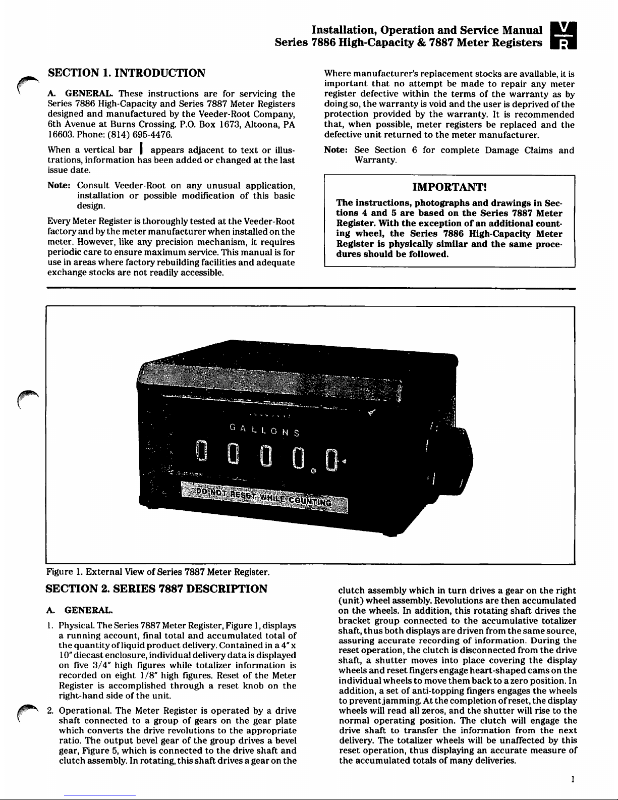
Figure
1.
External
View
of
Series
7887
Meter
Register.
SECTION
2.
SERIES
7887
DESCRIPTION
A.
GENERAL.
1.
Physical.
The
Series
7887
Meter
Register,
Figure
1,
displays
a
running
account,
final
total
and
accumulated
total
of
the
quantity
of
liquid
product
delivery.
Contained
in
a4"x
10"
diecast
enclosure,
individual
delivery
data
is
displayed
on
five
3/4"
high
figures
while
totalizer
information
is
recorded
on
eight 1 /8"
high
figures.
Reset
of
the
Meter
Register
is
accomplished
through a reset
knob
on
the
right-hand
side
of
the
unit.
2.
Operational.
The
Meter
Register
is
operated
by a drive
shaft
connected
to a group
of
gears
on
the
gear
plate
which
converts
the
drive
revolutions
to
the
appropriate
ratio.
The
output
bevel
gear of the
group
drives a bevel
gear,
Figure
5,
which
is
connected
to
the
drive shaft
and
clutch
assembly.
In
rotating,
this
shaft
drives a gear
on
the
clutch
assembly
which
in
turn
drives a gear
on
the
right
(unit)
wheel
assembly.
Revolutions
are
then
accumulated
on
the
wheels.
In
addition,
this
rotating
shaft
drives
the
bracket
group
connected
to
the
accumulative
totalizer
shaft,
thus
both
displays
are
driven
from
the
same
source,
assuring
accurate
recording
of
information.
During
the
reset
operation,
the
clutch
is
disconnected
from
the
drive
shaft, a shutter
moves
into
place
covering
the
display
wheels
and
reset
fingers
engage
heart-shaped
cams
on
the
individual
wheels
to
move
them
back
to a zero
position.
In
addition, a set
of
anti-topping
fingers
engages
the
wheels
to
prevent
jamming.
At
the
completion
of
reset,
the
display
wheels
will
read
all
zeros,
and
the shutter
will
rise
to
the
normal
operating
position.
The
clutch
will
engage
the
drive
shaft
to
transfer
the
information
from
the
next
delivery.
The
totalizer
wheels
will
be
unaffected
by
this
reset
operation,
thus
displaying
an
accurate
measure
of
the
accumulated
totals
of
many
deliveries.
1
Page 4
Installation,
Operation
and
Service
Manual
Series
7886
High-Capacity
&
7887
Meter
Registers
B.
SPECIFICATIONS.
Specifications
listed
are
standard
unless
otherwise
noted.
Optional
features
are
available
at
additional
cost.
Speed:
250
rpm.
Torque:
Average
running
torque
at
room
temperature
with
1:1
input: 4 oz-in.
During
display
wheel
transfer
from
all
9's
to
all
0's,
the
instantaneous
peak
torque
may
reach
40
oz-in.
Operating
Temperature
Range:
40°
to
+71°C
(-40°
to
+
160°F).
Number
of
Figures:
Meter
Register:
5.
Accumulative
Totalizer:
8
Size
of
Figures:
Meter
Register:
0.750"
high x 0.400"
wide
(19.05 x 10.16
mm).
Totalizer:
0.125"
high x 0.078"
wide
(3.175 x 1.98
mm).
Color
of
Figures:
White
on
black,
except
right-hand
totalizer
wheel
which
is
black
on
white
when
recording
tenths
of
units,
and
white
on
black
when
recording
whole
units.
Style
of
Figures:
Veeder-Root/Cornell
for
optimum
read
ability.
Character
Configuration:
0
to 9 (options
available).
Reset:
Single
handle
on
register.
Designed
for
one-handed
operation.
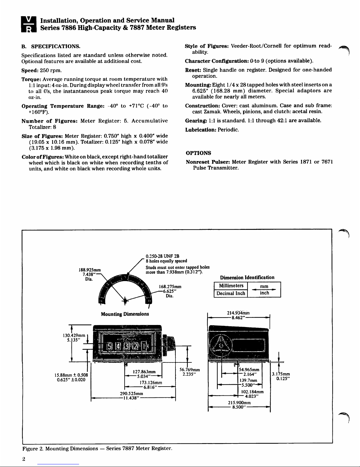
Mounting:
Eight 1 /4 x 28
tapped
holes
with
steel
inserts
on
a
6.625"
(168.28
mm)
diameter.
Special
adaptors
are
available
for
nearly
all
meters.
Construction:
Cover:
cast
aluminum.
Case
and
sub
frame:
cast
Zamak.
Wheels,
pinions,
and
clutch:
acetal
resin.
Gearing:
1:1
is
standard.
1:1
through
42:1
are
available.
Lubrication:
Periodic.
OPTIONS
Nonreset
Pulser:
Meter
Register
with
Series
1871
or
7671
Pulse
Transmitter.
k
\
188.925mm
7.438"
Dia.
0.250-28
UNF
2B
8
holes equally
spaced
Studs
must
not
enter
tapped
holes
more
than
7.938mm
(0.312").
168.275mm
6.625"
Dia.
Dimension
Identification
Mounting
Dimensions
214.934mm
-8.462"-
130.429mm
5.
35"
15.88mm + 0.508
0.625"
±0.020
127.863mm
-"
5.034
H
173.126mm
—
6.816
290.525mm
—11.438"
—
56.769mm
2.235"
54.965mm
2.164"
139.7mm
5.5OO"-*
3.175mm
0.125"
Figure
2.
Mounting
Dimensions — Series
7887
Meter
Register.
2
Page 5
Installation,
Operation
and
Service
Manual
Series
7886
High-Capacity
&
7887
Meter
Registers
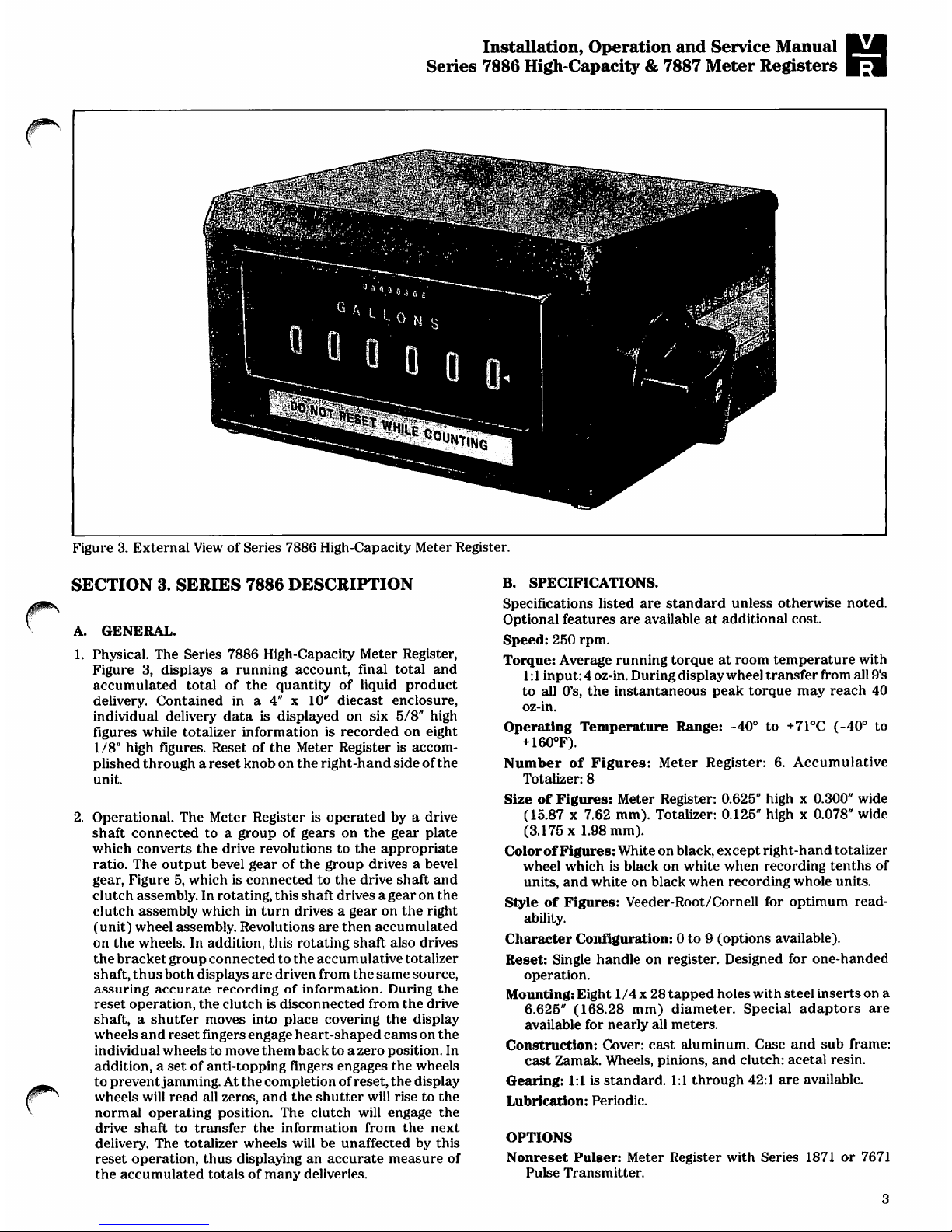
Figure
3.
External
View
of
Series
7886
High-Capacity
Meter
Register.
SECTION
3.
SERIES
7886
DESCRIPTION
A.
GENERAL.
1.
Physical.
The
Series
7886
High-Capacity
Meter
Register,
Figure
3,
displays a running
account,
final
total
and
accumulated
total
of
the
quantity
of
liquid
product
delivery.
Contained
in a 4" x 10"
diecast
enclosure,
individual
delivery
data
is
displayed
on
six
5/8"
high
figures
while
totalizer
information
is
recorded
on
eight
1/8"
high
figures.
Reset
of
the
Meter
Register
is
accom
plished
through a reset
knob
on
the
right-hand
side
of
the
unit.
2.
Operational.
The
Meter
Register
is
operated
by a drive
shaft
connected
to a group
of
gears
on
the
gear
plate
which
converts
the
drive
revolutions
to
the
appropriate
ratio.
The
output
bevel
gear
of
the
group
drives a bevel
gear,
Figure
5,
which
is
connected
to
the
drive shaft
and
clutch
assembly.
In
rotating,
this
shaft
drives
agear
on
the
clutch
assembly
which
in
turn
drives a gear
on
the
right
(unit)
wheel
assembly.
Revolutions
are
then
accumulated
on
the
wheels.
In
addition,
this
rotating
shaft
also
drives
the
bracket
group
connected
to
the
accumulative
totalizer
shaft,
thus both
displays
are driven
from
the
same
source,
assuring
accurate
recording
of
information.
During
the
reset
operation,
the
clutch
is
disconnected
from
the
drive
shaft, a shutter
moves
into
place
covering
the
display
wheels
and
reset
fingers
engage
heart-shaped
cams
on
the
individual
wheels
to
move
them
back
to a zero
position.
In
addition,
a
set
of
anti-topping
fingers
engages
the
wheels
to
prevent
jamming.
At
the
completion
of
reset,
the
display
wheels
will
read
all
zeros,
and
the
shutter
will
rise
to
the
normal
operating
position.
The
clutch
will
engage
the
drive
shaft
to
transfer
the
information
from
the
next
delivery.
The
totalizer
wheels
will
be
unaffected
by
this
reset
operation,
thus
displaying
an
accurate
measure
of
the
accumulated
totals
of
many
deliveries.
B.
SPECIFICATIONS.
Specifications
listed
are
standard
unless
otherwise
noted.
Optional
features
are
available
at
additional
cost.
Speed:
250 rpm.
Torque:
Average
running
torque
at
room
temperature
with
1:1
input: 4 oz-in.
During
display
wheel
transfer
from
all
9's
to
all
0's,
the
instantaneous
peak
torque
may
reach
40
oz-in.
Operating
Temperature
Range:
-40°
to
+71°C
(-40°
to
+
160°F).
Number
of
Figures:
Meter
Register:
6.
Accumulative
Totalizer:
8
Size
of
Figures:
Meter
Register:
0.625"
high x 0.300"
wide
(15.87 x 7.62
mm).
Totalizer:
0.125"
high x 0.078"
wide
(3.175x1.98
mm).
Color
of
Figures:
White
on
black,
except
right-hand
totalizer
wheel
which
is
black
on
white
when
recording tenths
of
units,
and
white
on
black
when
recording
whole
units.
Style
of
Figures:
Veeder-Root/Cornell
for
optimum
read
ability.
Character
Configuration:
0
to 9 (options
available).
Reset:
Single
handle
on
register.
Designed
for
one-handed
operation.
Mounting:
Eight
1/4 x 28
tapped
holes
with
steel
inserts
on
a
6.625"
(168.28
mm)
diameter.
Special
adaptors
are
available
for
nearly
all
meters.
Construction:
Cover:
cast
aluminum.
Case
and
sub
frame:
cast
Zamak.
Wheels,
pinions,
and
clutch:
acetal
resin.
Gearing:
1:1
is
standard.
1:1
through
42:1
are
available.
Lubrication:
Periodic.
OPTIONS
Nonreset
Pulser:
Meter
Register
with
Series
1871
or
7671
Pulse
Transmitter.
Page 6

Installation,
Operation
and
Service
Manual
Series
7886
High-Capacity
&
7887
Meter
Registers
188.925mm
7.438"
Dia.
0.250-28
UNF
2B
8
holes
equally
spaced
Studs
must
not
enter
tapped
holes
more
than
7.938mm
(0.312").
168.275mm
6.625"
Dia.
Mounting
Dimensions
130.429mm
15.88mm
±0.508
0.625"
+0.020
127.863mm
5.034
H
173.126mm
—
6.816
290.525mm
—11.438"
—
56.769mm
2.235"
Dimension
Identification
214.934mm
-8.462"-
54.965mm
2.164"
139.7mm
5.500"-*
3.175mm
0.125"
Figure
4.
Mounting
Dimensions — Series
7886
High-Capacity
Meter
Register.
Bracket-
Croup
Anli-Toppin.
Finger
Unit
Wheel
Shut
tor
Detent
Spring
lutch
Spring
Reset
Spring
Figure
5.
Internal
View
of
Series
7887
Meter
Register
(Series
7886
High-Capacity
Meter
Register
is
similar).
4
Page 7

Installation,
Operation
and
Service
Manual
Series
7886
High-Capacity
&
7887
Meter
Registers
SECTION
4.
PERIODIC
INSPECTION
(For
Series
7886
High-Capacity
and
Series
7887
Meter
Registers)
A.
GENERAL.
The
Meter
Register
is
fully
lubricated
and
properly
adjusted
at
manufacture.
However,
periodic
clean
ing
and
lubrication
are
required.
Judgement
of
the
intervals
at
which
the
meter
register
requires
such
service
must
necessarily
be
left
to
the
individual
user
due
to
varying
conditions
of
service.
Under
normal
conditions,
this
will
be
at
least
once a year,
or
after
each
2-1/2
million
units
of
measure
delivered,
whichever
comes
first.
B.
DISASSEMBLY
PRIOR
TO
CLEANING.
Remove
the
meter
register
from
its
housing
as
follows:
1.
Remove
the
bolts
securing
the
cover
(if
present)
to
the
top
of
the
housing.
These
bolts
are
hex
head
and
are
located
at
the
four
corners
of
the
bottom
of
the
housing.
Remove
the
cover.
2.
Remove
the
three
button-head
bolts
securing
the
meter
register
to
the
housing.
Remove
the
meter
register.
3.
Remove
the
screws
securing
the
gear
plate
to
the
bottom
of
the
housing.
Remove
the
gear
plate.
C.
CLEANING.
CAUTION:
DO
NOT
USE A WIRE
BRUSH.
1.
Wipe
bezel
crystal
with a clean
lint-free
rag.
2.
If
the
wheel
faces
are
dirty,
gently
clean
with a clean
lint-free
rag
dipped
in
mild
soapy
water.
3.
Clean
the
gears
on
the
base
plate
by
flushing
or
with
a
brush
dipped
in
solvent.
Blow
dry
with
compressed
air.
4.
Clean
housing
by
dipping, flushing
or
brushing
with
solvent.
Blow
dry
with
compressed
air.
D.
INSPECTION. A periodic
inspection
of
the
entire
meter
register,
housing
and
gear
plate
is
required
to
make
sure
that
they
function
properly,
parts
are
in
place,
and
no
binding
or
excessive
side-to-side
motion
of
shafts
occurs. A checklist
on
such
procedures
follows:
1.
Check
the
following
shafts
for
perceptible
side-to-side
motion.
Note:
Remove
the
meter
register
from
the
housing
before
checking
shaft
freedom.
a.
Wheel
Shaft
b.
Anti-Topping
Finger
Group
Shaft
c.
Reset
Finger
Group
Shaft
d.
Clutch
Group
Shaft
e.
Pinion
Shaft
2.
Temporarily
install
the
base
plate
and
meter
register
in
the
housing
and
check
for
proper
engagement
and
freedom
of
movement
of:
a.
All
gears
on
gear
plate.
b.
Output
bevel
gear
on
gear
plate
with
the
bevel
drive
gear
on
drive
shaft.
c.
57
tooth
gear
on
clutch
assembly
with
gear
on
right
wheel
assembly.
d.
Gear
drive
shaft
with gear
train
that
operates
the
totalizer,
and
gear
connecting
the
drive
train
to
the
totalizer.
3.
Rotate
drive
shaft
by
hand
to
see
that
unit
operates
freely
and
then
reset,
checking
for
proper
reset
and
shutter
action.
Adjust
pointer
after
reset
as
required.
4.
Check
all
screws,
retaining
rings
and
groove
pins
to
see
that
they
are
tight
and
seated
properly.
E.
LUBRICATION.
I.
Recommended
Lubricants
Note:
Chemlube
and
VTschem
products
are
manufactured
by
Ultrachem
Inc.,
1400
N.
Walnut
St.,
P.O.
Box
2053
Wilmington,
DE
19899
Oil:
Chemlube
201
or
equivalent
with a temperature
range
of
-65°F
to
+275°F
(-54°C
to
+135°C).
Grease:
Vischem
352
or
equivalent
with a temperature
range
of
-65°F
to
+300°F
(-54°C
to
+149°C).
Note:
All
lubricants
used
in
the
register
must
be of a type
which
remains
fluid
over
the
full
temperature
range
to
which
the
register
will
be
subjected.
Also,
they
should
not
oxidize
or
dry
out
leaving a gummy
or
perceptible
residue.
If
the
Chemlube
201
oil
lubricant
is
not
available,
a
substitute
with
equivalent
properties
may
be
used.
To
assist
field
personnel
in
obtaining
suitable
lubricants
for
the
meter
register
and
ticket
printers,
the
following
list
showing
equi
valent
lubricants
has
been
prepared:
OIL
AEROSHELL
FLUID
REGENT
SPINTEX
OIL
GARGOYLE
ARCTIC
OIL
CASTROL
HYSPIN
ANDEROL
AEROSHELL
ESSO
BEACON
ANDEROL
2.
Points
to
Lubricate
GREASE
NO.
3
60
LIGHT
40
401D
14
325
795
Oil:
All
points
indicated
as
"Oil"
on
Figure 6
should
be
lubricated
with
oil
as
described
above.
This
includes
all
shafts,
studs,
and
bosses
on
which a moving
part
bears.
Grease:
Grease
should
be
applied
to
all
points
indicated
as
"Grease"
on
Figure
6.
This
includes
gears
and
the
no-back
ratchet
and
pinion.
Note:
The
oil
and
grease
should
be
applied
with a small
brush
to
make
certain
that
all
areas
will
be
properly
lubricated.
In
this
manner,
the
amount
of
lubricant
being
used
will
be
more
easily
controlled.
Page 8

iM
Installation,
Operation
and
Service
Manual
JJ
Series
7886
High-Capacity
&
7887
Meter
Registers
s/s/s//////////////////
//////. 7 '///
SECTION
Y-Y
WITH
BEZEL
REMOVED
W
Grease
Grease Grease
Gre?se
Y^
/Oil
Oil
Oil
CLUTCH
SHAFT
VIEW
Oil
Oil Oil
ANTI-TOPPING
FINGER
SHAFT
VIEW
Grease
Oil
VIEW
V-V
PARTIAL
VIEW
Z-Z
Grease
Oil
Grease
SECTION
W-W
Oil'
PINION
SHAFT
VIEW
Oil
11
Oil
^Grease
Oil
Oil
RESET
FINGER
SHAFT
VIEW
Oil
"Grease
OH
P
Grease
Grease 5 Places
"
WHEEL
SHAFT
VIEW
Figure
6.
Lubrication
Points.
Page 9

Installation,
Operation
and
Service
Manual
Series
7886
High-Capacity
&
7887
Meter
Registers
F.
TROUBLESHOOTING.
Table 1 is
used
to
assist
in
locating
problems
and making
repairs
and
corrections.
In
some
problems,
similar
defects
can
be
produced
by
several
causes
of
an
entirely
different
nature.
Cause
of
the
trouble
must
be
determined
and
the
correction
made.
Table
1.
Troubleshooting
Page 10

Installation,
Operation
and
Service
Manual
Series
7886
High-Capacity
&
7887
Meter
Registers
SECTION
5.
DISASSEMBLY
AND
ASSEMBLY
(For
Series
7886
High-Capacity
and
Series
7887
Meter
Registers)
A.
GENERAL.
When
disassembling
the
meter
register,
be
extremely
careful
not
to lose
or
intermix
any
of
the
washers
found on
the
shafts.
By
doing
so,
potential
problems
with
end-play
and
backlash
adjustments
will
be
greatly
lessened.
When
removing
retaining
rings
or
other
parts
from
shafts,
do
not
hold
the
shaft
with
any
tool
that
might
gouge
or
create
burrs
on
the
shaft.
B.
REMOVAL
OF
MAJOR
GROUPS.
Instructions
for
removal
of
all
shaft
groups
are
provided.
1.
If
present,
remove
the
retaining
ring
securing
the
reset
idler
gear
to
the
reset
idler
gear
shaft.
2.
Remove
retaining
rings
and
washers
securing
the
pinion,
reset,
anti-topping
and
clutch
shafts
to
the
right-hand
side
plate
(Figure
7).
Remove
screws
and
lockwasher
securing
the
totalizer
group
and
rear
mounting
bar
from
right-hand
side
plate.
3.
Remove
side
plate.
CAUTION:
DO
NOT
LOSE
OR
INTERMIX
WASHERS FROM
EACH
SHAFT.
Note:
Remove
only
those
shaft
groups
necessary
to
gain
access
to
parts
being
replaced.
^\
Accumulative
Totalizer
Group
Retaining
Screw
Pinion
Shaft
Stop
Shaft
Anti-Topping
Finger
Shaft
Clutch
Shaft
Rear
Mounting
Bar
Retaining
Screw
Reset
Shaft
Figure
7.
Right-Hand
Side
Plate.
Figure
8.
Left-Hand
Side
Plate.
8
Page 11

Installation,
Operation
and
Service
Manual
Series
7886
High-Capacity
&
7887
Meter
Registers
|-
4.
Clutch
Shaft
Group
Removal.
a.
Remove
retaining
ring
and
washers
securing
the
clutch
shaft
group
to
the
left-hand
side
plate.
See
Figure
8.
b.
Move
clutch
lever
group
so
clutch
is
free.
See
Figure
9.
Remove
clutch
shaft
group.
See
Paragraph
C, 1 for
parts
replacement.
5.
Reset
Finger
Group
Removal.
a.
Remove
retaining
ring
and
washer
securing
the
reset
group
to
the
left-hand
side
plate.
See
Figure
8.
b.
Disengage
the
reset
fingers
and
no-back
pawl
from
the
wheels.
See
Figure
10.
Remove
the
group.
See
Paragraph
C, 2 for
parts
replacement.
6.
Stop
Shaft
Removal.
a.
Remove
the
springs
from
between
the
anti-topping
fingers
and
the stop
shaft.
b.
Remove
the
spring
from
between
the
detent
lever
group
and
the
stop
shaft.
c.
Remove
the
stop
shaft.
7.
Anti-Topping
Finger
Group
Removal.
a.
Remove
the
retaining
ring
and
washers
securing
the
anti-topping
finger
group
shaft
to
the
left-hand
side
plate.
See
Figure
8.
b.
Disengage
the
anti-topping
fingers
and
the
clutch
lever
group
from
the
wheels.
See
Figure
11.
c.
Remove
the
group
from
the
side
plate.
See
Paragraph
C,
3
for
parts
replacement,
8.
Totalizer
Group
Removal.
a.
Remove
the
screws
securing
the
totalizer
group
to
the
left-hand
and
right-hand
side
plates.
See
Figures 7 and
8.
b.
Remove
the
totalizer
group.
c.
No
additional
disassembly
of
the
totalizer
is
possible.
If
the
totalizer
is
inoperable,
replace
the
group.
j^
Note:
If
the
inoperable
totalizer
has a small
bevel
gear
(approx.
11/32
inch
dia.)
on
the
drive
shaft,
replace
the
bracket
group on
the
leftside
frame
as
well
as
the
totalizer
group
(see
Figure
31
and
Paragraph
D, 7 and
E,
5).
Remove
the
screw
holding
the
pointer
onto
the
old
totalizer
and
save
for
installation
on
new
totalizer.
9.
Pinion
Removal.
a.
Remove
retaining
ring
securing
pinion
shaft
to
the
left-
hand
side
plate.
See
Figure
8.
b.
Rotate
the
detent
lever
group
so
it
will
clear
the
reset
cam.
Remove
shaft.
c.
Remove
pinions,
detent
lever
group
washers
and
re
taining
rings
from
shaft.
10.
Wheel
Group
Removal.
a.
Mark
relationship
of
reset
gear
to
wheel
group
shaft
to
assure
proper
positioning
during
assembly.
b.
Remove
pin
securing
reset
gear
to
the
wheel
group
shaft.
c.
Remove
gear,
retaining
ring
and
washer.
Remove
shaft.
See
Paragraph
C, 4 for
parts
replacement.
Figure
10.
Reset
Finger
Group
Removal.
Figure
9.
Clutch
Group
Removal
Figure
11.
Anti-Topping
Finger
Group
Removal.
Page 12

Installation,
Operation
and
Service
Manual
Series
7886
High-Capacily
&
7887
Meter
Registers
C.
INDIVIDUAL
PARTS
REPLACEMENT
1.
Clutch
Shaft
Parts
Replacement.
See
Figure
12.
a.
Totalizer
and
Drive
Bevel
Gears.
(1)
Drift
out
pin
securing
gear
to
shaft.
(2)
Remove
gear.
(3)
Remove
retaining
rings
and
washers
that
position
drive
gear.
Do
not
change
the
order
of
the
rings
and
washers.
(4)
Drift
out
pin
holding
drive
gear
and
remove
gear.
(5)
Install
new
gear,
pin,
retaining
rings
and
washers.
Use
new
pin
if
required.
(6)
Install
totalizer
bevel
gear
and
secure
with
pin.
CAUTION:
CHECK
SHAFT
FOR
STRAIGHTNESS
AFTER
PINNING. A BENT
SHAFT
WILL
CAUSE
BINDING
DURING
DRIVING
OF
METER
REGISTER.
CLUTCH
MUST NOT
BE
DISASSEMBLED
OR
REPLACED
AS
AN
INDIVIDUAL
GROUP.
IF
CLUTCH
IS
BROKEN
OR
MALFUNCTIONS,
REPLACE
COMPLETE
SHAFT
AND
CLUTCH
AS
AN
ASSEMBLY.
2.
Reset
Finger
Group
Parts
Replacement.
See
Figure
13.
Individual
reset
fingers,
reset
arm,
no-back
pawl
and
pawl
spring
may
be
replaced
as
required.
a
Remove
retaining
rings
and
appropriate
washer
to
reach
particular
part.
b.
Replace
defective
items
with
new
part.
Assemble
remaining
parts
on
shaft.
Install
retaining
rings
and
washers.
Check
end
play
per
Figure
28.
3.
Anti-Topping
Finger
Group
Parts
Replacement.
See
Figure
14.
Individual
anti-topping
fingers,
reset
lever
and
clutch
lever
may
be
replaced
as
required.
a.
Remove
retaining
rings,
washers
and
parts
as
required
to
get
to
part
that
is
to
be
replaced.
b.
Install
parts,
retaining
rings
and
washers
in
the
se
quence
shown
in
Figure
14.
Be
sure
to
install
parts
so
they
are
in
the
proper
direction.
Check
end
play
per
Figure
28.
4.
Wheel
Group
Parts
Replacement.
See
Figures
15,
16,
17
and
18.
The
reset
cam,
individual
wheels,
locking
discs
and
eccentrics
may
be
replaced
as
required.
a.
Remove
retaining
rings,
washers
and
key
as
required
to
remove
reset
cam,
wheels,
locking
discs
and
eccentrics.
b.
Install
parts,
retaining
rings,
washers
and
key
in
the
sequence
shown
in
Figure
17.
When
installing
wheels,
be
sure
the
pin
on
the
locking
disc
engages
the
groove
in
the
wheel
as
shown
in
Figure
18.
Check
end
play
per
Figure
28.
D.
INSTALLATION
OF
MAJOR
GROUPS
Prior to
installing
each
shaft,
lubricate
per
Paragraph E in
Section
4.
During
assembly,
do
not
intermix
washers
from
one
shaft
to
another.
1.
Wheel
Group
Installation.
a.
If
not
present,
install
a
0.030
inch
thick
washer
over
the
end
of
the
wheel
group
shaft
opposite
the
cam.
b.
Install
the
shaft
into
the
proper
hole
in
the
left-hand
side
plate.
See
Figure
8.
2.
Anti-Topping
Finger
Group
Installation.
See
Figure
19.
a.
Hold
wheel
and
side
plate
assembly
upside
down.
b.
Install
anti-topping
finger
group
in
proper
hole
in
left-
hand
side
plate
(see
Figure
8).
Be
sure
all
fingers
and
clutch
lever
are
free
of
wheels
and
the
pin
on
the
reset
lever
engages
the
track
on
the
cam.
•Clutch
Drive
Gear
Retaining
Rings
and
Washers
Pin
Bevel
Gear
Figure
12.
Clutch
Shaft
Group.
\
Figure
13.
Reset
Finger
Group.
Figure
14.
Anti-Topping
Finger
Group.
10
Page 13

Installation,
Operation
and
Service
Manual
Series
7886
High-Capacity
&
7887
Meter
Registers
|?
c.
Seat
the
shaft,
install
washers
and
retaining
ring
to
secure
shaft
to
left-hand
side
plate.
d.
See
that
all
fingers
are
free
to
engage
wheels.
3.
Stop
Shaft
Installation.
a.
Install
retaining
rings
on
ends
of
shaft.
b.
Insert
stop
shaft
into
proper
hole
in
left-hand
side
plate.
See
Figure
8.
4.
Reset
Finger
Shaft
Group
Installation.
a.
Rotate
no-back
pawl
so that
spring
puts
pawl
under
tension.
Slip
an
elastic
band
over
the
reset
fingers
and
pawl
to
hold
pawl
in
position.
See
Figure
20.
b.
Install
shaft
into
left-hand
side
plate
and
secure
with
retaining
ring
and
washers.
See
Figure
8.
c.
Engage
pin
on
reset
lever
group
with
slot
in
reset
arm.
See
Figure
22.
5.
Clutch
Shaft
Group
Installation.
a.
Install
shaft
in
proper
hole
in
left-hand
side
plate.
Add
washers
and
secure
with
retaining
ring.
See
Figure
8.
b.
Make
sure
that
bevel
gears
that
drive
the
totalizer
are
free
to
turn.
Figure
17.
Locking
Disc,
Eccentric
and Washer
Removal
and
Installation.
Figure
15.
Reset
Cam
Removal.
Figure
18.
Unit
Wheel
Installation.
Retaining
Rin
and Washers
Anti-Topping
Finger
Group
Figure
16.
Unit
Wheel
Removal.
Figure
19.
Anti-Topping
Finger
Group
Installation.
11
Page 14

Installation,
Operation
and
Service
Manual
Series
7886
High-Capacity
&
7887
Meter
Registers
6.
Right-Hand
Side
Plate
Installation
a.
Hold
meter
register
assembly
as
shown
in
Figure
22
and
place a rubber
band
around
the
assembly
to
hold
it
together.
Be
sure
the
pin
in
the
reset
lever
group
remains
engaged
in
the
slot
in
the
reset
arm.
b.
Install
side
plate
over
wheel
shaft
first,
then
engage
the
other
shafts.
c.
Temporarily
secure
the
side
plate to
the
rear
mounting
bar
with
screws.
7.
Bracket
Group
(if
required)
and
Totalizer
Installation.
a.
If
required,
install
new
bracket
group
to
inside
of
left
side
frame
and
secure
with
two
screws
and
lock-
washers.
See
Figure
31.
b.
Install
pointer
with
screw
(saved
from
old
totalizer)
onto
new
totalizer
group
but
do
not
tighten
screw
securely.
Pointer
position
must
be
adjusted
after
totalizer
group
is
installed.
See
Paragraph
F,
2.
c.
Install
the
totalizer
group
so
that
the
bevel
gear
is
in
mesh
with
the
top
bevel
gear
on
the
bracket
group
and
secure
with
retaining
screws.
For
adjustment
of
bevel
gear
drive,
see
Paragraph
E,
5.
8.
Spring
Installation.
a.
See
Figure
23
for
identification
of
springs.
\,
b.
Install
the
five
anti-topping
finger
springs
between
the
anti-topping
fingers
and
the
stop
shaft.
See
Figure
24.
c.
Install
the
reset
spring
between
the
reset
lever
and
the
pinion
shaft.
d.
Install
the detent
spring
between
the
detent
lever
group
and
the
stop
shaft.
e.
Install
the
clutch
spring
between
the
clutch
lever
group
and
the
pinion
shaft.
9.
Pinion
Shaft
Assembly
Installation
a.
If
not
previously
accomplished,
remove
all
parts
from
pinion
shaft.
b.
Rotate
wheel
shaft
so
reset
fingers
are
fully
engaged
in
the
heart-shaped
cams
on
each
wheel.
c.
Place
pinions,
with
short
finger
up,
in
between
each
wheel
as
shown
in
Figure
25.
d.
Install
the
end
of
the
shaft
closest
to
the
two
retaining
ring
slots
into
the
left-hand
side
plate
and
through
each
pinion.
Figure
20.
Reset
Finger
Shaft
Group
Preparation
For
Installation.
Figure
22.
Preparation
For
Side
Plate
Installation.
y
_
Figure
21.
Reset
Lever
Group
Pin
Engagement.
12
Figure
23.
Spring
Identification.
Page 15

Installation,
Operation
and
Service
Manual
Series
7886
High-Capacity
&
7887
Meter
Registers
e.
Install
washers
and
detent
lever
group
onto
shaft
and
engage
shutter
with
tab
on
detent
lever.
f.
Push
shaft
through
the
right-hand
side
plate
and
secure
with
washer
and
retaining
ring.
g.
Secure
detent
lever
group
into
position
with
retaining
rings.
h.
After
assembly,
rotate
wheel
shaft
to
make
sure
all
pinions
have been
positioned
properly.
If
binding
occurs,
reposition
pinions
per
step
c.
10.
Reset
Gear
Installation.
a.
Install
reset
gear
on
wheel
shaft,
aligning
orientation
mark
made
at
disassembly.
b.
Secure
gear
to
shaft
with
pin.
11.
Reset
Idler
Gear
Installation.
a.
If
present,
install
reset
idler
gear
on
the
reset
idler
gear
shaft.
See
Figure
8.
b.
Secure
with
retaining
ring.
Note:
This
gear
will
be
timed
when
the
meter
duplicator
and
meter
register
are
assembled
together.
Figure
24.
Anti-Topping
Finger
Spring
Installation.
Figure
26.
Installation
Of
Meter
Register
Onto
Mounting
Fixture.
Figure
25.
Pinion
Positioning.
Figure
27.
Securing
Mounting
Fixture.
13
Page 16

Installation,
Operation
and
Service
Manual
Series
7886
High-Capacity
&
7887
Meter
Registers
Adjust
to give
proper
engagement
with
Drive
Gear on
Gear
Plate
End
Play
O.OO5-O.O12
inch
Maintain
proper
engagement
with
Totalizer
bevel
gear.
CLUTCH
SHAFT
Washer
Clutch
and
Anti-topping
Shafts
end
play
for
proper
actuation
of Clutch
End
Play
0.007
inch
maximum
Adjust
Detent
Lever
for
best
possible
engagement
while
maintaining
0.005-0.010
inch
end
play
to
End
Play
0.005-0.012
inch
PINION
SHAFT
End
play
of
0.002-0.007
inch
between
retaining
rings
Adjust
No-back
Pawl
for
best
possible
engagement
while
maintaining
0.005-0.010
inch
end
play
End
Play
0.005-0.012
inch
0.005-0.010
inch
end
play
between
retaining
rings.
ANTI-TOPPING
FINGER
SHAFT
RESET
FINGER
SHAFT
0.009-0.016
inch
end
play
between
retaining
rings
of
each
wheel.
i
[I
t
Adjust
for
best possible
engagement
of
Reset
Cam
while
maintaining
0.005-0.010
inch
end
play.
End
Play
0.005-0.012
inch
WHEEL
SHAFT
S
Figure
28.
End
Play
Limits.
14
Page 17

Installation,
Operation
and
Service
Manual
Series
7886
High-Capacity
&
7887
Meter
Registers
#
E.
FINAL
CHECKS
AND
ADJUSTMENTS.
1.
End
Play
Check:
Check
end
play
(back
and
forth
motion)
of
shafts
and
parts
as
follows:
a.
For
proper
measurement,
the
meter
register
must
be
installed
in
the
TD-42383
mounting
fixture,
Figure
26,
to
constrain
the
frame
into
the
same
position
that,
it
is
when
installed
in
the
housing.
b.
Secure
the
meter
register
to
the
fixture
with
two 1 ,'4-28
button-head
bolts.
See
Figure
27.
c.
Take
end
play
measurements
of
each
shaft.
Add
or
subtract
washers
as
necessary
to
obtain
correct
end
play.
2.
Input
Drive
Bevel
Gear
Engagement
Adjustment.
a.
Install
the
gear
plate
onto
the
fixture
using
the
appropriate
hardware.
b.
Remove
the
retaining
ring
behind
the
bevel
gear
and
add
or
subtract
washers
as
required
for
proper
mesh
between
the
bevel
gear
on
the
gear
plate
and
the
drive
bevel
gear
on
the
clutch
shaft.
The
shaft
end
play
must
be
maintained
as
specified
in
Figure
28.
c.
Replace
the
retaining
ring
after
adjustment.
3.
Clutch
Lever
Positioning
Adjustment.
a.
Rotate
the
reset
gear
until
the
clutch
is
fully
disengaged.
b.
Measure
the clearances
as
shown
in
Figure
29.
c.
If
the
dimensions
cannot
be
obtained,
add
or
remove
washers
as
required,
or
replace
the
clutch
and
shaft.
d.
The
amount
of
face
engagement
between
the
spur
gear
on
the
input
clutch
and
the
first
wheel
should
be
75%
±
20%.
4.
Wheel
Brake
Adjustment.
a.
Rotate
reset
gear
to
position
cam
as
shown
in
Figure
30.
b.
Measure
clearance
between
brake
and
first
wheel.
If
clearance
is
not
within
the
dimensions
given,
adjust
brake
by
loosening
screw
and
moving
brake
into
position.
c.
Remove
the
meter
register
from
the
fixture
by removing
the
two
button-head
screws.
Remove
the
gear
plate
from
the
fixture.
5.
Gearing
Adjustment
for
Totalizer.
See
Figure
31.
Loosen
set
screw
on
bottom
bevel
gear.
Mesh
the
top
bevel
gear
tightly
with
the
totalizer
bevel
gear.
Press
the
register
clutch
shaft
toward
the
left
side
frame.
Adjust
the
bottom
bevel
gear
such
that
it
has
0.012 -0.015
end
play
when
meshing
with
the
clutch
shaft
bevel
gear.
Tighten
set
screw
and
secure
with a sealant
(Loctite
222
or
equivalent)
to
prevent
loosening.
6.
Apply
Anderol
L-795
or
equivalent
grease
on
teeth
of
bevel
gears.
7.
Backlash
Compensating
Mechanism
Adjustment
for
EEC
UNITS
ONLY.
While
unit
is
running
at
100-200
RPM,
adjust
screw
so
that
pawl
is
approximately
in
the
middle
of
clip
as
shown
in
Figure
32
(on
Page
16).
Oscillation
of
pawl
is
permissible.
To
check
for
proper
operation,
use a 1:1
gear
plate
and
operate
register
at
100-200
RPM.
Stop
counting,
hold
input
shaft
of gear
plate
and
reset
register.
Wheel
should
reset
so
that
some
part
of
graduation
at
zero
always
aligns
with
pointer.
Spur
Gear-
*—0.005
inch
min.
Lever
0.015
inch
min.
Figure
29.
Clutch
Lever
Adjustment.
First
Wheel
Detent
Cam
Small
Dia.
Figure
30.
Brake
Adjustment.
Figure
31.
Inside
Left
Side
Plate
of
Meter
Register.
15
Page 18

Installation,
Operation
and
Service
Manual
Series
7886
High-Capacity
&
7887
Meter
Registers
Figure
32.
Backlash
Compensating
Mechanism
(EEC
UNITS)
F.
OPERATIONAL
CHECK.
Before
returning
the
meter
register
to
normal
service,
check
that
it
operates
properly
as
follows:
1.
Rotate
the
input
bevel
gear
and
see
that
the
totalizer
and
individual
delivery
wheels
are
driven
and
that
they
record
the
same
amount.
There
should be
no
binding
or
drag.
2.
Rotate
the
reset
gear
and
see
that
the
shutter
drops
into
place,
the
wheels
all
reset
and
that
there
is
no
binding
or
drag.
At
the
completion
of
reset,
the
zeros
should
align
with
the
pointer.
3.
See
Troubleshooting,
Table
1.
Page
5,
if
there
are
any
problems.
SECTION
6.
DAMAGE
CLAIMS
AND
WARRANTY
A.
DAMAGE
CLAIMS
1.
Thoroughly
examine
the
enclosure
as
soon
as
it
is
received.
If
damaged,
write
on
the
face
of
the
freight
bill
a
complete
and
detailed
description
of
the
damage.
Have
the
carrier's
agent
sign
the
description.
Note:
Insist
that
the
carrier's
agent
verify
the
inspection
and
sign
the
description.
2.
Immediately
notify
the
delivering
carrier
of
damage
or
loss.
This
notification
may
be
given
either
in
person
or
by
telephone.
Written
confirmation
must
be
mailed
within
48
hours.
Railroads
and
motor
carriers
are
understandably
reluctant
to
make
adjustments
for
damaged
merchandise
unless
inspected
and
reported
promptly.
3.
Risk
of
loss
of,
or
damage
to
merchandise
remains
with
the
Buyer.
It is
the
Buyer's
responsibility
to
file a claim
with
the
carrier
involved.
4.
Immediately
advise
your
Veeder-Root
representative,
distributor,
or
the
factory
so
that
we
may
assist
you.
B.
RETURN
SHIPPING.
All
shipments
of
Veeder-Root
products
must
be
prepaid.
Equipment
must
be
packed
in
a
strong
exterior
container
and
surrounded
by
shock
absorb
ing
material.
Veeder-Root
will
accept
no
liability
for
damage
caused
by
improper
packing.
It
is
suggested
that
the
original
shipping
container
be
used
if
it
is
available.
Address
sh
ipment
to
Veeder-Root
Co.,
6th
Avenue
at
Burns
Crossing,
P.O.
Box
1073,
Altoona.PA
16603.
C.
WARRANTY
AND
CONDITIONS
1.
WARRANTY.
We
warrant
that
our
products
shall
be
free
from
defects
in
material
and
workmanship
for a period
of
one
year
from
the
date
of
shipment
thereof
or
the
product's
total
rated
life,
whichever
first
occurs.
Within
the
warranty
period
we
shall
repair
or
replace
such
products
which
are
returned
to
us
with
shipping
charges prepaid
and
which
are
deter
mined
by
us
to
be
defective.
This
warranty
will
not
apply
to
any
product
which
has
been
subjected
to
misuse,
negligence,
or
accident;
or
misapplied;
or
used
in
violation
of
product
manuals,
instructions,
or
warnings;
or
modified
or
repaired
by
unauthorized
persons;
or
improperly
installed.
2.
INSPECTION.
You
shall
inspect
the
product
promptly
after
receipt
and
shall
notify
us
at
our
Altoona
office,
in
writing,
of
any
claims,
including
claims
of
breach
of
warranty,
within
thirty
days
after
you
discover
or
should
have
dis
covered
the
facts
upon
which
the
claim
is
based.
Your
failure
to
give
written
notice
of a claim
within
the
time
period
shall
be
deemed
to
be a waiver
of
such
claim.
3.
LIMITATION
OF
REMEDY AND
WARRANTY.
The
provisions
of
Paragraph 1 are
our
sole
obligation
and
exclude
all
other
remedies
or
warranties,
express
or
implied,
including
warranties
of
MERCHANTABILITY
and
FITNESS
FOR A PARTICULAR
PURPOSE,
whether
or
not
purposes
or
specifications
are
described
herein.
We
further
disclaim
any
responsibility
whatsoever
to
you
or
to
any
other
person
for injury
to
person
or
damage
to
or
loss
of
property
or
value
caused
by
any
product
which
has
been
subjected
to
misuse,
negligence,
or
accident;
or
mis
applied;
or
used
in
violation
of
product
manuals,
instruc
tions,
or
warnings;
or
modified
or
repaired
by
unauthorized
persons;
or
improperly
installed.
4.
LIMITATION
OF
DAMAGES.
Under
no
circumstances
shall
we
be
liable
for
any
incidental,
consequential
or
special
damages,
losses
or
expenses
arising
from
this
contract
or
its
performance
or
in
connection
with
the
use
of,
or
inability
to
use,
our product
for
any
purpose
whatsoever.
5.
LIMITATION
OF
ACTIONS.
No
action
regardless
of
form
arising
out
of
this
contract
may
be
commenced
more
than
one
year
after
the
cause
of
action
has
accrued,
except
an
action
for
nonpayment.
6.
COLLATERAL
PROMISES.
There
are
no
represen
tations,
warranties,
or
conditions
express
or
implied,
statu
tory
or
otherwise
except
those
herein
contained,
and
no
agreements
or
waivers
collateral
hereto
shall
be
binding
on
either
party
unless
in
writ
ing
and
signed
by
you
and
accepted
by
us
at
our
Altoona
office.
7.
INTERPRETATION.
Rights
and
liabilities
arising
out
of
any
contract
with us
shall
be
determined
under
the
Uniform
Commercial
Code
as
enacted
in
Connecticut.
%
Page 19

1
VEEDER-ROOT
"^
Hm
Petroleum
Products
6th
Avenue
at
Bums
Crossing,
P.O.
Box
1673.
Altoona,
PA
16603-1673
Phone
(800)
873-3313,
Fax
(800)
234-5350.
or
Phone
(814)
695-4476,
Fax
(814)
695-7605
BRAZIL:
Sau
Paulo • CANADA:
Mississauga,
Ontario
•
ENGLAND:
Richmond
Surrey ■ FRANCE:
Rungis
Cedex • GERMANY:
Neuhausen/Filder
•
SINGAPORE:
Singapore
251325
(REV.
B)
13355
Replaces
12569
 Loading...