

Veeder-Root Red Jacket Maxxum Big-Flo Quick-Set Series, Red Jacket Maxxum Big-Flo Quick-Set P200R1 Installation, Operation & Service Manual

D051-301, Rev. V
Installation, Operation, & Service
Maxxum® Big-Flo
®
6” Submersible Pump
Red Jacket® Quick-Set® Submersible Pump

Notice
Veeder-Root makes no warranty of any kind with regard to this publication, including, but not limited to, the implied warranties of
merchantability and fitness for a particular purpose.
Veeder-Root shall not be liable for errors contained herein or for incidental or consequential damages in connection with the
furnishing, performance, or use of this publication.
Veeder-Root reserves the right to change system options or features, or the information contained in this publication.
This publication contains proprietary information which is protected by copyright. All rights reserved. No part of this publication
may be photocopied, reproduced, or translated to another language without the prior written consent of Veeder-Root.
Contact Red Jacket Technical Support for additional troubleshooting information at 800-323-1799.
DAMAGE GOODS/LOST EQUIPMENT
Thoroughly examine all components and units as soon as they are received. If any cartons are damaged or missing, write a
complete and detailed description of the damage or shortage on the face of the freight bill. The carrier's agent must verify the
inspection and sign the description. Refuse only the damaged product, not the entire shipment.
VR must be notified of any damages and/or shortages within 30 days of receipt of the shipment, as stated in our Terms and
Conditions.
VEEDER-ROOT’S PREFERRED CARRIER
1. Fax Bill of Lading to V/R Customer Service at 800-234-5350.
2. Call V/R Customer Service at 800-873-3313 with the specific part numbers and quantities that were received damaged or
lost.
3. VR will file the claim with the carrier and replace the damaged/missing product at no charge to the customer. Customer
Service will work with production facility to have the replacement product shipped as soon as possible.
CUSTOMER’S PREFERRED CARRIER
1. Customer files claim with carrier.
2. Customer may submit a replacement purchase order. Customer Service will work with production facility to have the
replacement product shipped as soon as possible.
3. If “lost” equipment is delivered at a later date and is not needed, VR will allow a Return to Stock without a restocking fee.
4. VR will NOT be responsible for any compensation when a customer chooses their own carrier.
RETURN SHIPPING
For the parts return procedure, please follow the instructions in the “General Returned Goods Policy” pages of the “Policies and
Literature” section of the Veeder-Root North American Red Jacket Mechanical Products Price Book. Veeder-Root will not accept
any return product without a Return Goods Authorization (RGA) number clearly printed on the outside of the package.
Veeder-Root 2017. All rights reserved.

Introduction
Safety Precautions ............................................................................................................1
Warnings and Instructions ................................................................................................3
IMportant Safety Information ....................................................................................3
Preliminary Precautions............................................................................................3
Requirements For Use .............................................................................................4
Operating Precautions..............................................................................................4
Fuel Compatibilities ..........................................................................................................4
Installation
Installation Safety Notices Attention Installer ....................................................................5
Follow These Directions Carefully ....................................................................................6
Installing The Pumping Unit ..............................................................................................6
Attaching the Expansion Relief Vent Line .........................................................................7
Wiring the Conduit Box .....................................................................................................8
Wiring Instructions- 208-230 Volt Single Phase Pumps ...........................................9
Wiring Instructions - 208-230, 380/415 or 575 Volt Three-Phase Pumps ................9
Starting the System and Completing the Installation ......................................................16
Floating Suction Installation Information .........................................................................19
Installing A Big Flo Diaphragm Valve ..............................................................................20
Attaching the Siphon & Vacuum Lines with Factory Installed Siphon Assemblies .........22
Installing Two Pumps for Tandem Operation ..................................................................23
Table of Contents
Testing the Installation
Testing the Piping ...........................................................................................................26
Testing the Tank .............................................................................................................27
Purging the System ........................................................................................................27
Adjusting the Pressurstat Line Relief Pressure ...............................................................28
Service and Repair
Removing the Extracta Assembly ...................................................................................29
Procedure for Removal of Plug-in Type Pump - Motor Assembly ..................................30
Installing the Extracta Assembly (Ref. Figure 19) ...........................................................31
Replacing the Check Valve Assembly ............................................................................33
Repairing the Check Valve Lock-down Screw And Seals ...............................................34
Parts
6” Maxxum Big Flo - Repair Parts Packer Manifold Assembly Parts - Side View ...........37
6” Maxxum Big Flo - Repair Parts Packer Manifold Assembly Parts - Top View ............38
6” Maxxum Big Flo - Repair Parts Yoke Assembly .........................................................39
UL Listed Motor Control Box For 2HP Pumps Model P200H1-CB .................................40
Red Jacket Replacement Pump Motors .........................................................................41
Magnetic Contactor For 2, 3, And 5 HP 3-Phase Pumps ...............................................41
Appendix A: ATEX Safety Instructions
Appendix B: Declaration of Conformity
Appendix C: FDNY Certificate of Approval
Appendix D: ANZe Conditions of Certification
iii

Figures
Table of Contents
Figure 1. Maxxum Packer-Manifold Assembly .......................................................7
Figure 2. Conduit Box - Yoke Assembly ................................................................8
Figure 3. Typical Mechanical Dispenser Representative Wiring Diagram,
1-Phase, Two-Wire Control ..................................................................11
Figure 4. Typical Mechanical Dispenser Motor Control Box, Wiring
Diagram, 2HP .......................................................................................12
Figure 5. Representative Wiring Diagram For Use With Switched
“Hot” Feed 208-230 Vac, 2HP Single-Phase Control Box ....................13
Figure 6. Representative Wiring Diagram, Three-Phase, Two-Wire Control .......14
Figure 7. Three-Wire, Three-Phase Motor Wiring Diagram .................................15
Figure 8. ..............................................................................................................16
Figure 9. ..............................................................................................................19
Figure 10. ..............................................................................................................21
Figure 11. ..............................................................................................................22
Figure 12. ..............................................................................................................23
Figure 13. Suggested Diagram For Wiring Dual Manifold System,
Two-Wire Control, 208/230 Single Phase .............................................24
Figure 14. Suggested Diagram For Wiring Dual Manifold System,
Three-Wire Control, 208/230 Single Phase ..........................................24
Figure 15. Suggested Diagram For Wiring Dual Manifold System,
Two-Wire Control, Three Phase ...........................................................25
Figure 16. Suggested Diagram For Wiring Dual Manifold System,
Three-Wire Control, Three Phase .........................................................25
Figure 17. Maxxum Packer-Manifold Assembly: Line And Tank Testing ...............26
Figure 18. Pressurstat - Pressure Adjustment .......................................................27
Figure 19. Maxxum - Extractable Section ..............................................................29
Figure 20. UMP - Discharge Head Assembly ........................................................32
Figure 21. Maxxum Check Valve Assembly ..........................................................33
Figure 22. Pressurstat And Check Valve Lock-Down Screw Assembly ................35
Figure 23. Check Valve And Pressurstat Assembly ..............................................36
Figure 24. Check Valve And Electrical Bushing Assembly ....................................37
Figure 25. Maxxum Packer-Manifold Assembly .....................................................38
Figure 26. Maxxum Yoke and Contractors Box Assembly .....................................39
Figure 27. 2HP, 1-Phase Control Box ....................................................................40
Tables
Table A. ..................................................................................................................5
Table B. ................................................................................................................17
Table C. ................................................................................................................17
Table D. ................................................................................................................18
Table E. ................................................................................................................30
Table F. ................................................................................................................32
Table G. ................................................................................................................36
Table H. ................................................................................................................37
Table I. ................................................................................................................38
Table J. ................................................................................................................39
Table K. ................................................................................................................40
Table L. ................................................................................................................41
Table M. ................................................................................................................41
iv
Introduction
OFF
WARNING
CAUTION
NOTICE
This manual provides step-by-step instructions for installing and wiring the Maxxum pump, tandem Maxxum pumps,
pump testing procedures, and pump service and repair.
Safety Precautions
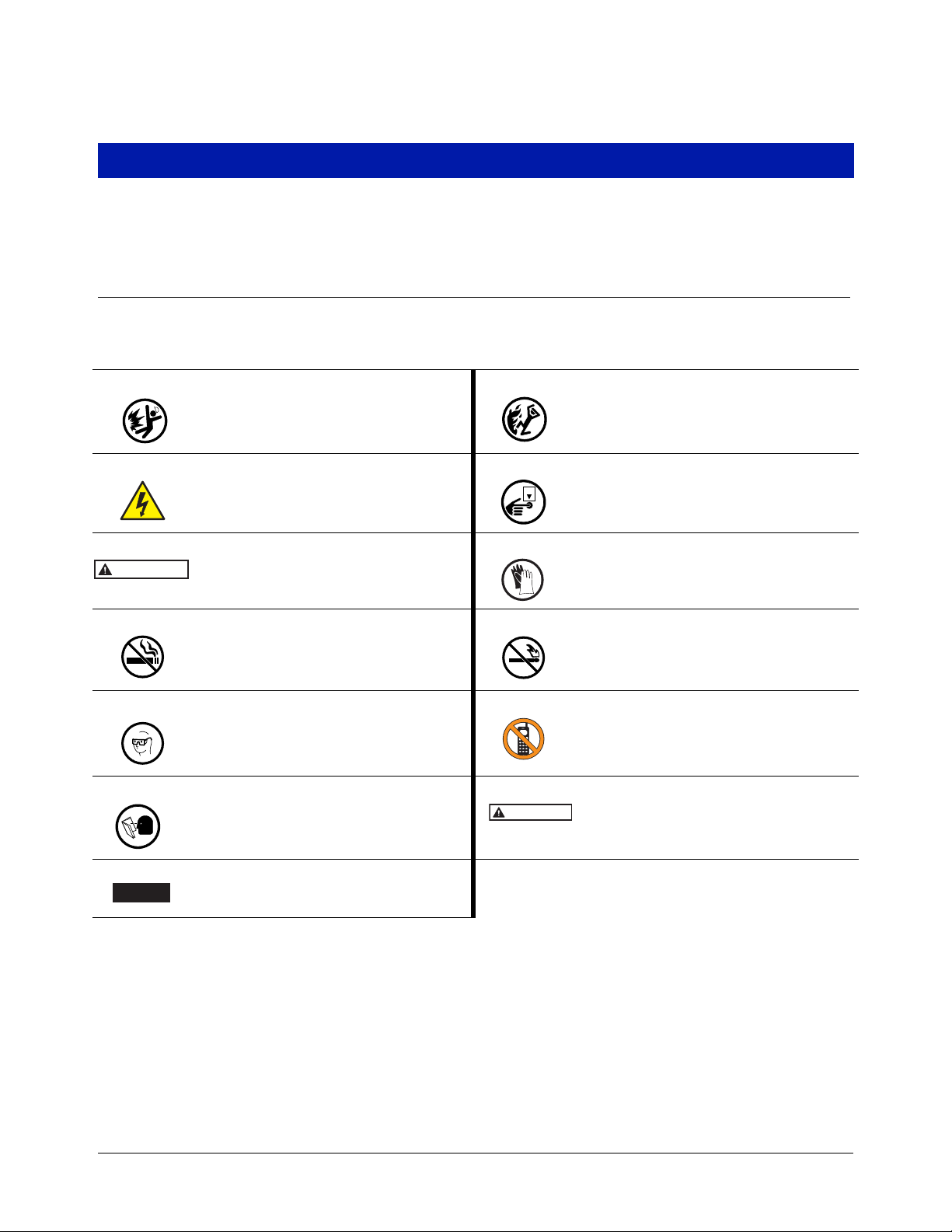
The following safety symbols are used throughout this manual to alert you to important safety hazards and
precautions.
EXPLOSIVE
Fuels and their vapors are extremely explosive
if ignited.
ELECTRICITY
High voltage exists in, and is supplied to, the
device. A potential shock hazard exists.
WARNING indicates a hazardous situation
which, if not avoided, could result in death
or serious injury.
NO SMOKING
Sparks and embers from burning cigarettes or
pipes can ignite fuels and their vapors.
EYE PROTECTION
Wear eye protection when working with pressurized fuel lines or epoxy sealant to avoid possible eye injury
READ ALL RELATED MANUALS
Knowledge of all related procedures before you
begin work is important. Read and understand
all manuals thoroughly. If you do not understand
a procedure, ask someone who does.
FLAMMABLE
Fuels and their vapors are extremely flammable.
TURN POWER OFF
Live power to a device creates a potential shock
hazard. Turn Off power to the device and associated accessories when servicing the unit.
GLOVES
Wear gloves to protect hands from irritation or
injury.
NO OPEN FLAMES
Open flames from matches, lighters, welding
torches, etc. can ignite fuels and their vapors.
TURN OFF CELL PHONES/PAGERS
Sparks from electronic devices in the vicinity of
gasoline storage tanks could cause an explosion
or fire resulting in bodily injury or death.
CAUTION indicates a hazardous situation
which, if not avoided, could result in minor or
moderate injury.
NOTICE is used to address practices not
related to physical injury..
1
Introduction Safety Precautions
OFF
WARNING
This product operates in the highly combustible atmosphere of a gasoline storage
tank.
FAILURE TO COMPLY WITH THE FOLLOWING WARNINGS AND SAFETY
PRECAUTIONS COULD CAUSE DAMAGE TO PROPERTY, ENVIRONMENT,
RESULTING IN SERIOUS INJURY OR DEATH.
1. All installation work must comply with the latest issue of the National
Electrical Code (NFPA 70), the Code for Motor Fuel Dispensing Facilities and
Repair Garages (NFPA 30A), and any European, national, state, and local
code requirements that apply.
2. Turn off, tag, and lockout power to the STP before connecting or servicing the
STP.
3. Before installing pipe threads apply an adequate amount of fresh, UL
classified for petroleum, non-setting thread sealant.
4. When servicing unit, use non-sparking tools and use caution when removing
or installing equipment to avoid generating a spark.
5. To protect yourself and others from serious injury, death, or substantial
property damage, carefully read and follow all warnings and instructions in
this manual.
In addition to the specified torque values noted in this manual, when properly tightened, all flanged fittings should
have metal-to-metal contact.
2
Introduction Warnings and Instructions
WARNING
WARNING
Warnings and Instructions
IMPORTANT SAFETY INFORMATION
This section introduces the hazards and safety precautions associated with installing,
inspecting, maintaining or servicing this product. Before performing any task on this
product, read this safety information and the applicable sections in this manual, where
additional hazards and safety precautions for your task will be found. Fire, explosion,
electrical shock or pressure release could occur and cause damage to property,
environment, resulting in serious injury or death, if these safe service procedures are
not followed.
PRELIMINARY PRECAUTIONS
You are working in a potentially dangerous environment of flammable fuels, vapors,
and high voltage or pressures. Only trained or authorized individuals knowledgeable in
the related procedures should install, inspect, maintain or service this equipment.
Read the Manual
Read, understand and follow this manual and any other la
you do not understand a procedure, call 1-800-323-1799 to locate a qualified technician. It is imperative to your
safety and the safety of others to understand the procedures before beginning work. Make sure your
employees and any service contractors read and follow the instructions.
Follow the Regulations
Applicable information is available in National Fire Protection Association (NFPA) 30A; Code for Motor Field
Dispensing Facilities and Repair Garages, NFPA 70; National Electrical Code (NEC), Occupational Safety and
Hazard Association (OSHA) regulations and federal, state, and local codes. All these regulations must be
followed. Failure to install, inspect, maintain or service this equipment in accordance with these codes, regulations
and standards may lead to legal citations with penalties or affect the safe use and operation of the equipment.
Prevent Explosions and Fires
Fuels and their vapors will explode or burn, if ignited. Spilled or leaking fuels cause vapors. Even filling customer
tanks will cause potentially dangerous vapors in the vicinity of the dispenser or island.
Working Alone
It is highly recommended that someone who is capable of rendering first aid be present during servicing.
Familiarize yourself with Cardiopulmonary Resuscitation (CPR) methods, if you work with or around high voltages.
This information is available from the American Red Cross. Always advise the station personnel about where you
will be working, and caution them not to activate power while you are working on the equipment. Use the OSHA
Lockout/Tagout procedures. If you are not familiar with this requirement, refer to OSHA documentation.
Working With Electricity Safely
Ensure that you use safe and established practices in working with electrical devices. Poorly wired devices may
cause a fire, explosion or electrical shock. Ensure that grounding connections are properly made. Ensure that you
do not pinch wires when replacing covers. Follow OSHA Lockout/Tagout requirements. Station employees and
service contractors need to understand and comply with this program completely to ensure safety while the
equipment is down. Before you start work, know the location of the Emergency Power Cutoff Switch (the ESTOP). This switch cuts off power to all fueling equipment and submerged turbine pumps and is to be used in the
event of an emergency. The buttons on the console at the cashier’s station WILL NOT shut off electrical power to
the pump/dispenser. This means that even if you press a button on the console labeled EMERGENCY STOP,
ALL STOP, PUMP STOP, or something similar, fuel may continue to flow uncontrolled.
bels or related materials supplied with this equipment. If
3

Introduction Fuel Compatibilities
WARNING
Hazardous Materials
Some materials may present a health hazard if not handled correctly. Ensure that you clean hands after handling
equipment. Do not place any equipment in the mouth.
FAILURE TO COMPLY WITH THE FOLLOWING WARNINGS AND SAFETY
PRECAUTIONS COULD CAUSE DAMAGE TO PROPERTY, ENVIRONMENT, RESULTING
IN SERIOUS INJURY OR DEATH.
FIRE HAZARD! Do NOT use power tools (Class I Division I and Class I Division II) during the installation or
maintenance of equipment. Sparking could ignite fuel or vapors, resulting in fire.
CHEMICAL EXPOSURE HAZARD! Wear appropriate safety equipment during installation or maintenance of
equipment. Avoid exposure to fuel and vapors. Prolonged exposure to fuel may cause severe skin irritations and
possible burns.
REQUIREMENTS FOR USE
• The Maxxum is designed for use only at facilities dispensing motor fuels.
• Application of the Maxxum must be consistent with NFPA Code 30A, OSHA regulations, and federal, state and
local fire codes, and other applicable local regulations.
• The selection of any Veeder-Root product must be based upon physical specifications and limitations and the
product’s compatibility with the materials to be handled. Veeder-Root makes no warranty of fitness for a
particular purpose.
• All Veeder-Root products should be used in accordance with applicable federal, state and local laws,
ordinances and regulations.
OPERATING PRECAUTIONS
• NO SMOKING. Extinguish all open flames and pilot lights, such as on RV appliances.
• TURN OFF cell phones and other electronic devices to avoid distractions while fueling.
Fuel Compatibilities
Pumps are designed to operate in a Class 1, Group D atmosphere and in accordance with CENELEC standard
and the European Directive 94/9/EC “Equipment for Potentially Explosive Atmoshpere” (II2 G Ex IIA T4).
All Models of the Maxxum are UL Listed for the Following Fuel Compatibility
Gasoline and up to
15%
Diesel Gasoline
Ethanol
The Maxxum is designed to be compatible with 100 percent gasoline, or diesel and 80 percent gasoline with 20
percent methanol, ethanol, TAME, ETBE, or MTBE .
15%
Methanol
20%
MTBE
20%
ETBE
20%
TAME
4
Installation
WARNING
This pumping system requires the following elements:
1. Discharge Manifold Assembly - Installed below grade (NEC/Class I, Group D, Division I area)
2. Motor-Pump Unit Assembly - Installed below grade (NEC/Class I, Group D, Division I area)
3. Control Box/Magnetic Starter
An “all inclusive” name plate will be found attached to the Extracta Head and can be inspected by removing
the manhole cover directly over the pump.
An additional name plate will be found on the control box. It is important to give the model number and serial
number of this pump when corresponding with the factory for any reason.
INSTALLATION SAFETY NOTICES ATTENTION INSTALLER
Read This Important Safety Information Before Beginning Work.
1. Units should be installed with manholes, or with discharge manifold casting above grade, to allow for ease in
servicing.
Red Jacket line leak detection systems do not function if the submersible pump runs
continuously. Running a pump continuously will cause line leak detection systems to
not function which results in a hazard that can cause damage to property, environment,
resulting in serious injury or death.
2. Never wire a submersible pump to run continuously at less than minimum flow rate. The units are designed to
operate continuously at or above minimum flow rate, or with an intermittent duty cycle, not to exceed 20 on/off
cycles per hour. Should it be necessary to operate a unit continuously or when the demand is at a rate less
than required per the information below, a bypass pipe should be installed in the piping to allow for continual
product recirculation back into the storage tank. Regulation of the bypass flow back to the tank can be
accomplished by correct sizing of the bypass line or use of a gate valve. The recommended minimum bypass
per unit is shown in Table A.
Table A.
60 Hz, 208-240, 575 Volt
Two Stage Units
P200J1-2MB = 15 GPM P300J17-3HB = 20GPM
P200J4-2MB = 15 GPM P500J17-3K = 25 GPM
P300J4-2HB = 20 GPM P300J16-3HB = 20GPM
P500J4-2K = 25 GPM P500J16-3K = 25 GPM
P200J6-2K = 25 GPM
50 Hz 380-415 Volt
Three Stage Units
3. Red Jacket submersibles are not designed to handle abrasives or foreign particles in the product being
pumped.
4. Product temperature must never exceed 105°F (41°C) as the submersible motors are equipped with thermal
overload protection. Product temperature higher than 105°F (41°C) may result in tripping of the thermal
overload protector.
5

Installation Follow These Directions Carefully
WARNING
WARNING
5. Pumping water will overload the motor and damage the motor bearings.
6. These units are designed for use in Class I, Group D atmospheres.
7. Install pumping system in accordance to applicable codes.
Proper motor protection must be used on three phase pump models, or motor warranty is void. To maintain warranty, the magnetic starters used must be supplied by Red
Jacket, or have equivalent protection features defined as follows:
- 3-leg protection
- Properly sized quick trip heaters, and
- Ambient temperature compensated overloads.
8. The UMP (Unitized-Motor-Pump) contains no serviceable parts (other than the foot valve) and should not be
modified or adjusted.
Follow These Directions Carefully
Check these points before installing.
1. The power supply against the equipment voltage rating. For 3 phase units, request the power company identify
and tag the service wires for L-1, L-2, L-3 phase sequence.
2. Be certain that the pump with the siphon valve is installed into the correct tank.
3. Check the equipment which was received against Table B and Figure 8 for the tank diameter and bury depth.
Before installing pipe threads apply an adequate amount of fresh, UL classified for petroleum, non-setting thread sealant.
4. Apply thread sealant to the six-inch riser/flange male threads. Thread it into the tank port. Tighten the riser/
flange until the joint is water tight.
Installing The Pumping Unit
1. Apply a gasket compound to the bottom surface of the manifold and press the gasket onto the manifold’s
mating surface so the holes in the gasket and manifold align (reference Figure 1).
2. Coat the exposed surface of the gasket with gasket compound.
WARNING
3. Insert three 3/4-inch bolts, provided, and torque them to 200 ft-lb (271 N•m).
Confirm that the lifting eyebolts are properly torqued to 10 ft-lbs (13.6 N•m) with a
minimum of 6 full threads installed. Occasionally, eyebolts are removed after pump installation and corrosion may occur in the threaded areas of the extractable and the
eyebolt. If corrosion has occurred, the extractable and eyebolt should be replaced.
Utilize BOTH lifting eyebolts to suspend the pump vertically and lower the pumping
unit into position. Do not allow the gasket to contact the riser flange until the bolt
holes in the flange are aligned with those in the manifold and the discharge port is
aimed in the desired direction.
6
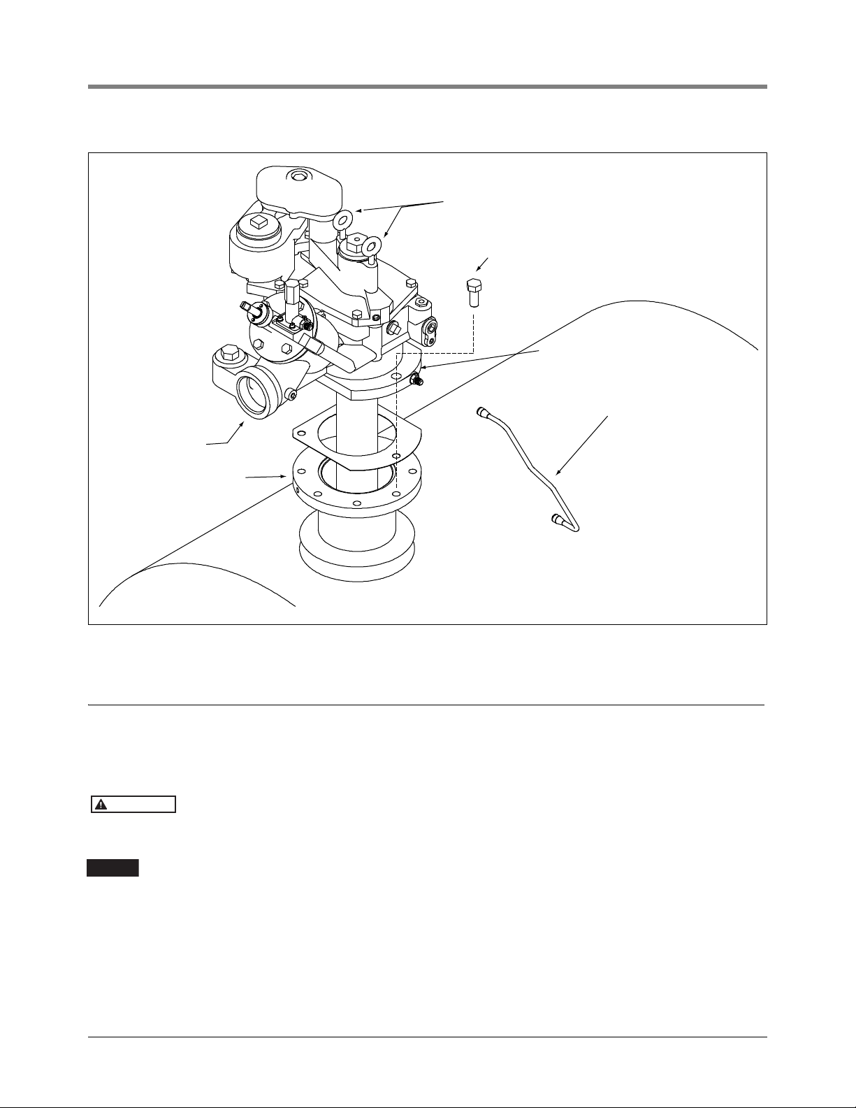
Installation Attaching the Expansion Relief Vent Line
Lifting eyes
Bolt torque 200 ft-lb. (3 places)
Manifold
Vent line
6" NPT riser
flange
3" NPT or BSP
discharge port
rj/051-301-1.eps
WARNING
NOTICE
Attaching the Expansion Relief Vent Line
1. Remove the metal protective shipping caps from the flare fittings (reference Figure 1).
2. Attach the vent line taking care not to cross thread the fittings.
3. Tighten the fittings 1/6 to 1/4 turn beyond hand tight.
4. Install the piping to the manifold discharge port. Pipe sealant should be used in this joint.
Line check-valves are not required since the pump has a built in check-valve. However, whenever two pumps are
manifolded together to the same discharge piping, check valves with expansion relief are required and should be
installed in the discharge piping of each pump, as close to the pump manifold as possible.
See instructions “INSTALLING TWO PUMPS FOR TANDEM OPERATION” and Figure 12.
Figure 1. Maxxum Packer-Manifold Assembly
Before installing pipe threads apply an adequate amount of fresh, UL classified for petroleum, nonsetting thread sealant.
Installation of a ball valve is recommended on the discharge side of the pump or discharge
of the “Big Flo” leak detector housing if used. This will aid in troubleshooting and line testing.
7
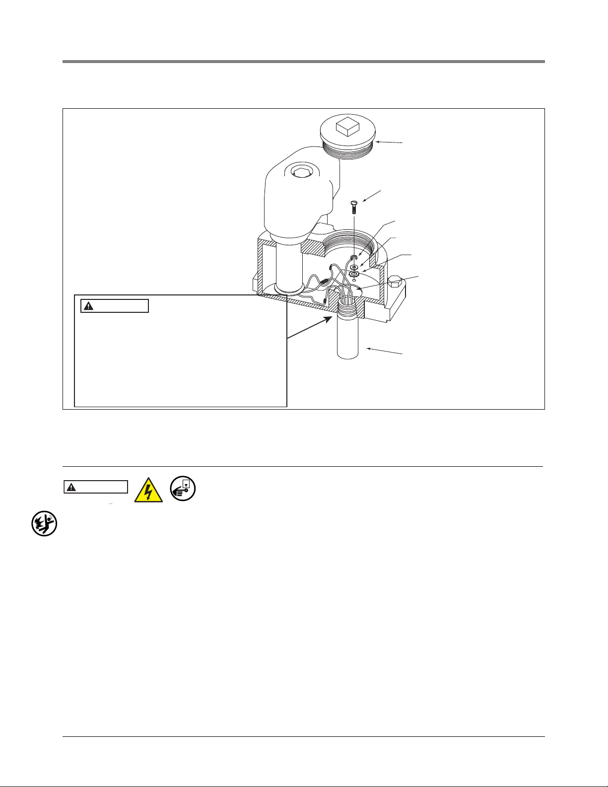
Installation Wiring the Conduit Box
(1" Conduit)
Conduit from control box
Power and thermal overload
leads to pump
O-ring
Ground wire
Ground wire screw
1. For European installations, the End User must
use an ATEX EEX d IIB certified cable gland or
stopping box.
2. Use suitable AUS EX, ANZEx or IECEx certified
cable gland or flameproof entry device when
equipment is installed in accordance with ANZEx
certification for connection of the external circuit
conductors to the motor conductors used to close
the 1" NPT conduit connection.
Cup washer terminal
External toothed washer
rj/051-301-2.eps
WARNING
OFF
WARNING
Wiring the Conduit Box
When servicing equipment, use non-sparking tools and use caution when removing or installing
equipment to avoid generating a spark.
1. Connect the electrical conduit through the approved fittings to the conduit box.
2. Remove the conduit box cover.
3. Connect the wires from the power supply to the wires in the conduit box.
4. Install the gound wire from the power panel.
5. Sparingly lubricate the o-ring before screwing the cover into the manifold. Use light grease, oil, or petroleum
jelly. Replace the conduit box cover. Do not use pipe sealant on the conduit box cover’s threads. Torque to 35
ft-lb (50 N•m).
Figure 2. Conduit Box - Yoke Assembly
Disconnect, lock out, and tag power at the panel before servicing the
pump.
8

Installation Wiring the Conduit Box
CAUTION
NOTICE
Wiring Instructions- 208-230 Volt Single Phase Pumps
The motor control box must be located away from the fueling area in a non-hazardous location (see Figure 3).
1. Connect the single phase 208-230 V power supply from the distribution panel to terminals L1 and L2 in the
motor control box. Each control box should be wired through a separate fused disconnect switch or circuit
breaker (including neutral, when used), furnished by customer.
2. Using properly color coded wires, connect wires from the red, black, orange and two blue terminals on motor
control box terminal strip to the corresponding color coded wires in the junction box of the proper submerged
pump.
The “on-off” control station must be of explosion-proof construction. Where loading racks and dispensers are
served by the same submerged pump, the 2-wire switches must be connected in parallel so the submerged
pump can be controlled from any dispenser or any loading rack.
3. Connect wires from terminal Blue-1 and terminal 3 in motor control box to dispenser control switches (if
dispensers are used) and “on-off” switch at loading rack as shown in Figure 3.
4. The pumps are equipped with a no-liquid, over-temperature switch in the motor and an overload switch in the
motor control box which will cut out if the motor is overloaded. If the pump fails to operate, or stops, when
there is sufficient product in the storage tank, check the manual overload reset switch in the control box cover.
Wait 10 minutes for the overload protector to cool off and then press the reset button.
If the reset button will not stay in position this indicates an overloaded motor, or a
short to ground. This condition must be corrected. If the reset button stays in but the
motor will not pump or continue to run, the tank is dry.
5. If an external pilot light is desired to indicate when the submerged pump is operating, wire as shown in
Figure 3, Figure 4 or Figure 5. Should this light continue to burn when all switches atdispensers and loading
racks are off, this indicates that one of the dispenser switches is out of adjustment. On installations with no
external pilot light, the submerged pump should be checked to make sure it is not operating when all switches
are turned off.
6. The magnetic contactor coil is shipped ready to accept 208-230 volts. No changes are required unless a 110-
120 volt coil is desired.
Wiring Instructions - 208-230, 380/415 or 575 Volt Three-Phase Pumps
On some installations, “phase converters” are used to obtain a three-phase power supply
from a single-phase power source. The use of phase converters may cause an imbalance
between the three phases and cause damage to the motor. For this reason, these
requirements must be followed in order to maintain warranty coverage.
• Static phase converters must not be used. Only rotary or electric phase converters are
allowed.
• The horsepower rating of the phase converter must be equal to at least three times the
horsepower rating of the pump(s).
• Current imbalance must not exceed 10% under varying flow conditions.
• Proper three-leg quick trip overloads must be used.
1. Installations where the magnetic starter is located away from the loading rack in a nonhazardous location. (See
Figure 6)
a. Connect the three phase power supply from the master panel to terminals L1, L2 and L3 in the magnetic
starter.
b. Using properly color coded wires, connect a black wire from terminal T1 in the magnetic starter to the
black motor lead, in the junction box of the proper submerged pump. Connect an orange wire from starter
terminal T2 to the orange motor lead and red wire from terminal T3 to the red motor lead. (See Figure 6
and Figure 7.)
9

Installation Wiring the Conduit Box
NOTICE
WARNING
c. There are two remaining blue wires in the submerged pump junction box. Connect either blue wire to one
side of the ‘on-off’ controls or switched ‘hot’ from the electronic dispenser or Isotrol (dispenser handle
isolation). The ‘on-off’ controls must be of explosion-proof construction if located in a hazardous location.
Connect the other blue wire to the appropriate terminal on the other side of the ‘on-off’ controls. See
specific wiring diagrams provided with the magnetic starters matching pump voltage, coil voltage and type
of pump control.
d. Installations using loading racks only, may be connected for 2- or 3-wire control. For 3-wire control
(Figure 7), connect a black wire from terminal 3 in the magnetic starter to the ‘on-off’ switch. Connect a
red wire from terminal 2 in the magnetic starter to the ‘on-off’ switch. Connect either blue wire to the other
side of the ‘on-off’ switch and connect the other blue wire to L1 of the magnetic starter.
3-wire control requires the use of an auxiliary contact in the magnetic starter. This auxiliary
contact is standard equipment in the G.E. starters supplied by Red Jacket.
Installations with the magnetic starter in a hazardous location require explosion-proof
magnetic starters. The wiring is the same as for general purpose enclosures. (Section
1).
2. Install proper overload heaters in magnetic starter matching starter manufacturer and amperage rating of the
pump.
3. Motor Rotation
Where it is not convenient to predetermine the power supply phase rotation, proper rotation can be determined by pump performance. Pump head pressure and capacity will be considerably less than rated when rotating backwards.
Connect the pump motor leads to terminal T1, T2 and T3 of the magnetic starter observing color code shown
in Figure 6 and Figure 7. With ample product in the tank and the system purged of air, start the motor and
make a pressure gauge reading of the system pressure with the discharge valves closed; or, open one valve
and calculate pumping rate.
Next, reverse power leads at L1 and L2. Repeat either pressure or capacity tests, as described above. If results are higher than the first test, the rotation of the second test is correct. If the second test gives lower performance than the first, reconnect the power leads to L1 and L2 (as under test 1) for correct rotation.
Where the power supply has been properly marked L1, L2 and L3 in accordance with accepted phase rotation standards, it is possible to predetermine the proper rotation of these units. The motor power leads are color coded black, orange and red, and if connected through the magnetic starter to L1, L2 and L3 respectively,
the motor pump unit will rotate in the correct direction. It is recommended, however, that the performance
tests always be made whether or not the power supply has been properly “phased out”.
10
Installation Wiring the Conduit Box
LINE
1
230V
115 115
LINE
2
ORANGE
BLACK
RED
BLUE
BLUE
1
2
3
EXT
PILOT
Grey
White
Seal
Seal
(Blue)1
Orange
Black
Red
(Black)3
On/Off
switch
To neutral of
115/230V
supply
Black
Customers 115V external
pilot light 50W max.
To neutral of
115/230V supply
The control box
must be grounded
for personal safety.
Refer to the National
Electrical Codes and
applicable local codes
for proper grounding
procedures.
115V Lighting circuit
(where needed) from
distribution panel
Locate seals where
required by local code
Motor control
and pilot light
circuit
Lighting circuit
Dial and dome lights
Pilot light 115V, 50W max.
Double pole motor switch
Blue
rj/051-301-3.eps
P200R1, 208-230V, 2HP
SINGLE PHASE
Figure 3. Typical Mechanical Dispenser Representative Wiring Diagram, 1-Phase, Two-Wire Control
11
 Loading...