

Page 1

Technical Installation Guide
EMR4
Manual No: 577014-322 ● Revision: B
Page 2

Notice
Veeder-Root makes no warranty of any kind with regard to this publication, including, but not limited to, the implied warranties of
merchantability and fitness for a particular purpose.
Veeder-Root shall not be liable for errors contained herein or for incidental or consequential damages in
connection with the furnishing, performance, or use of this publication.
Veeder-Root reserves the right to change system options or features, or the information contained in this publication.
This publication contains proprietary information which is protected by copyright. All rights reserved. No part of this publication may be
photocopied, reproduced, or translated to another language without the prior written consent of Veeder-Root.
Contact Technical Support for additional troubleshooting information at 800-323-1799.
DAMAGE CLAIMS / LOST EQUIPMENT
Thoroughly examine all components and units as soon as they are received. If any cartons are damaged or missing, write a complete
and detailed description of the damage or shortage on the face of the freight bill. The carrier's agent must verify the inspection and sign
the description. Refuse only the damaged product, not the entire shipment.
Veeder-Root must be notified of any damages and/or shortages within 30 days of receipt of the shipment, as stated in our Terms and
Conditions.
VEEDER-ROOT’S PREFERRED CARRIER
1. Contact Veeder-Root Customer Service at 800-873-3313 with the specific part numbers and quantities that were missing or
received damaged.
2. Fax signed Bill of Lading (BOL) to Veeder-Root Customer Service at 800-234-5350.
3. Veeder-Root will file the claim with the carrier and replace the damaged/missing product at no charge to the customer. Customer
Service will work with production facility to have the replacement product shipped as soon as possible.
CUSTOMER’S PREFERRED CARRIER
1. It is the customer’s responsibility to file a claim with their carrier.
2. Customer may submit a replacement purchase order. Customer is responsible for all charges and freight associated with
replacement order. Customer Service will work with production facility to have the replacement product shipped as soon as
possible.
3. If “lost” equipment is delivered at a later date and is not needed, Veeder-Root will allow a Return to Stock without a restocking fee.
4. Veeder-Root will NOT be responsible for any compensation when a customer chooses their own carrier.
RETURN SHIPPING
For the parts return procedure, please follow the appropriate instructions in the EMR Products General Returned Goods Policy pages
in the EMR4 Products price list. Veeder-Root will not accept any return product without a Return Goods Authorization (RGA) number
clearly printed on the outside of the package.
©Veeder-Root 2018. All rights reserved
.
Page 3

Safety Information
Safety Warnings ...............................................................................................................2
Special Conditions for Safe Use .......................................................................................2
EMR4 Truck Installation
Installing The Interconnection Box (IB) .............................................................................4
Input Power – Critical Ground Connection ........................................................................4
2-Stage Solenoid Valve Connections .......................................................................8
Valve Operation With The EMR4 .............................................................................8
3-Way Safety Valve for Truck LP Gas Systems ...............................................................9
Installing The 3-way Valve........................................................................................9
Solenoid Valves......................................................................................................12
Wiring The Display Head ................................................................................................14
C&C Mode Switch ...........................................................................................................16
Installing Optional Keypad Kit - Right or Left Side ..........................................................16
IInstalling The Remote Display (Optional) ......................................................................16
Installing The Remote Pulser (Optional) .........................................................................19
Pulse Encoder Specifications.................................................................................19
EMR4 Terminal & Fueling Depot Installation
Wiring The Display Head ................................................................................................21
Installing The Interconnect Box (IB) ................................................................................22
National Electrical Code Compliance .....................................................................22
Grounding...............................................................................................................22
Wire Type for Metallic or PVC Conduit...................................................................23
Wire Length ............................................................................................................23
Mounting and Wiring the IB Unit.............................................................................23
Solenoid Valves......................................................................................................23
Power Conditioning Requirements .................................................................................26
Wire Size And/or Distance Limitations ...................................................................26
Pulse Output Limits ................................................................................................29
EMR4 – Legal Disclaimer Notice ....................................................................................29
Table of Contents
Figures
EMR4 System Specifications
System Power .................................................................................................................30
Component Location .......................................................................................................30
Appendix A: EMR4 Safety Instructions & System Specifications
Figure 1. Example EMR4 truck Installation With 2 Display Heads And
Optional Remote Pulser ..........................................................................3
Figure 2. IB Physical Dimensions (Shown With Cover Removed) .........................6
Figure 3. EMR4 IB Box Wiring Connections ..........................................................7
Figure 4. 2-Stage Solenoid Valve ..........................................................................8
Figure 5. Connecting 3-Way Valve To Neptune Meter -
Truck LP Gas Installations ....................................................................10
Figure 6. Connecting 3-Way Valve To L.C./TCS Meter -
Truck LP Gas Installations ....................................................................11
Figure 7. Connecting 3-Way Valve To The Interconnect Box ..............................12
Figure 8. Example Wiring Connections For DC And AC Solenoid Valves ...........13
Figure 9. Display Head Cable Connections .........................................................15
Figure 10. Remote Display Assembly ....................................................................17
iii
Page 4

Tables
Table of Contents
Figure 11. Remote Display Connections (Rear Cover Removed) .........................18
Figure 12. Wiring Connections In Remote Pulser (Top Cover Removed) .............19
Figure 13. Example Terminal Fueling Depot Installation With 2 Display Heads
And Optional Remote Pulser ................................................................20
Figure 14. Display Head Cable Connections .........................................................22
Figure 15. EMR4 IB Box Wiring Connections ........................................................24
Figure 16. Example Terminal Wiring Connections For DC And
AC Solenoid Valves ..............................................................................25
Figure 17. Digi-Key Power Supply Wiring Diagram ...............................................26
Figure 18. Wiring Pulse Output To A TLS-350 Console ........................................27
Figure 19. Wiring Pulse Output To A TLS-450/TLS4 Console ...............................28
Table 1. 2-Stage Solenoid Wiring ............................................................................8
Table 2. Remote Display (84559X-00X) Components ..........................................16
Table 3. System Component Dimensions ............................................................30
Table 4. Remote Pulser Dimensions ....................................................................31
Table A-1. System Component Information ...........................................................A-3
Table A-2. Remote Pulser Information ................................................................... A-3
iv
Page 5
Safety Information
OFF
WARNING
NOTICE
CAUTION
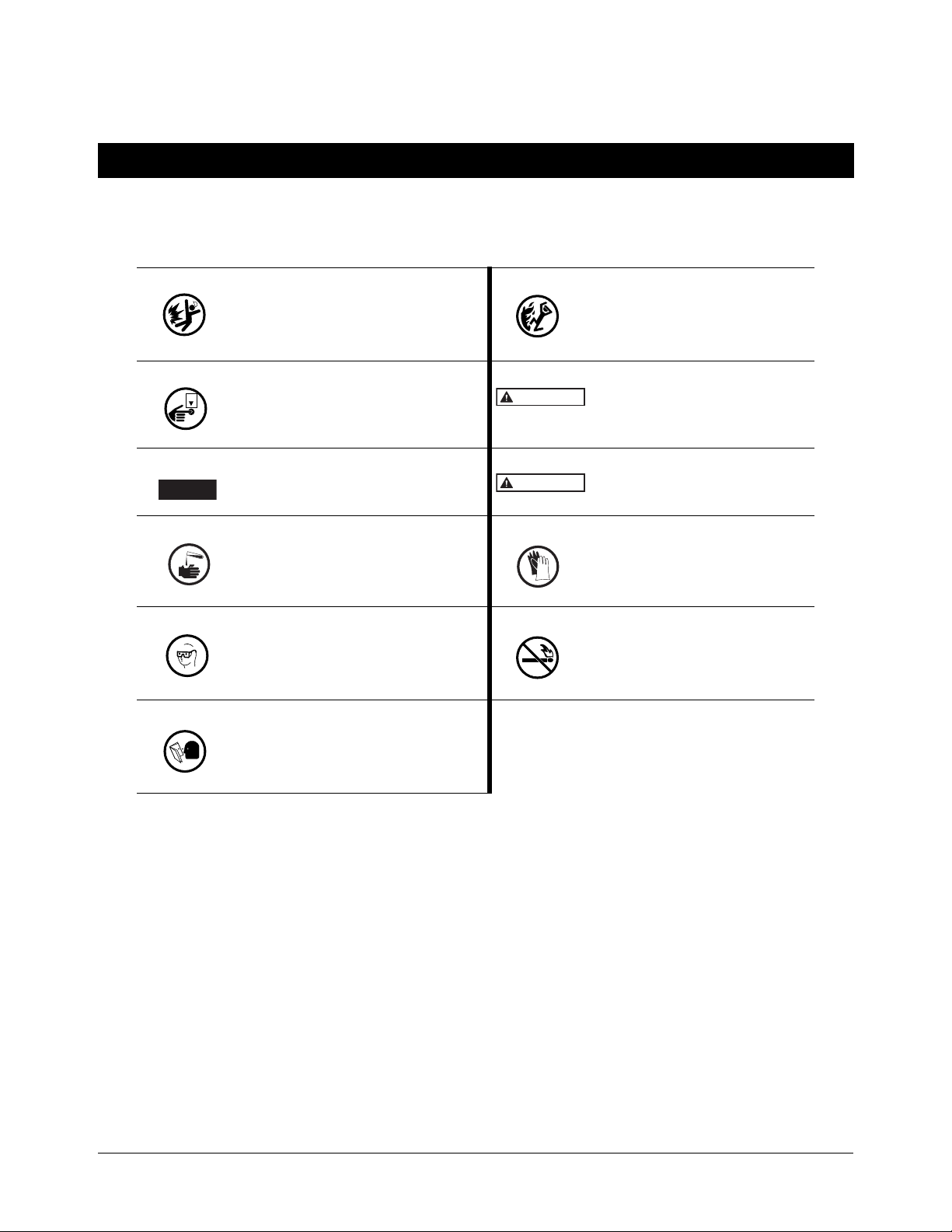
The following safety symbols may be used throughout this manual to alert you to important safety hazards and
precautions
EXPLOSIVE
Fuels and their vapors are extremely explosive if ignited.
TURN POWER OFF
Live power to a device creates a potential
shock hazard. Turn Off power to the device
and associated accessories when servicing
the unit.
NOTICE
Alerts the user to practices not related to
physical injury.
INJURY
Careless or improper handling of materials
can result in bodily injury.
WEAR EYE PROTECTION
Fuel spray from residual pressure in the lines
can cause serious eye injuries. Epoxy sealant can cause eye injury. Always wear eye
protection when working with pressurized
lines and epoxy mixtures.
READ ALL RELATED MANUALS
Knowledge of all related procedures before
you begin work is important. Read and
understand all manuals thoroughly. If you do
not understand a procedure, ask someone
who does.
FLAMMABLE
Fuels and their vapors are extremely
flammable.
WARNING
Indicates a hazardous situation which,
if not avoided, could result in death or
serious injury.
CAUTION
Indicates a hazardous situation which,
if not avoided, could result in minor or
moderate injury.
GLOVES
Wear gloves to protect hands from irritation or injury.
NO OPEN FLAMES
Open flames from matches, lighters,
welding torches, etc. can ignite fuels
and their vapors.
1
Page 6
Safety Information Safety Warnings
NOTICE
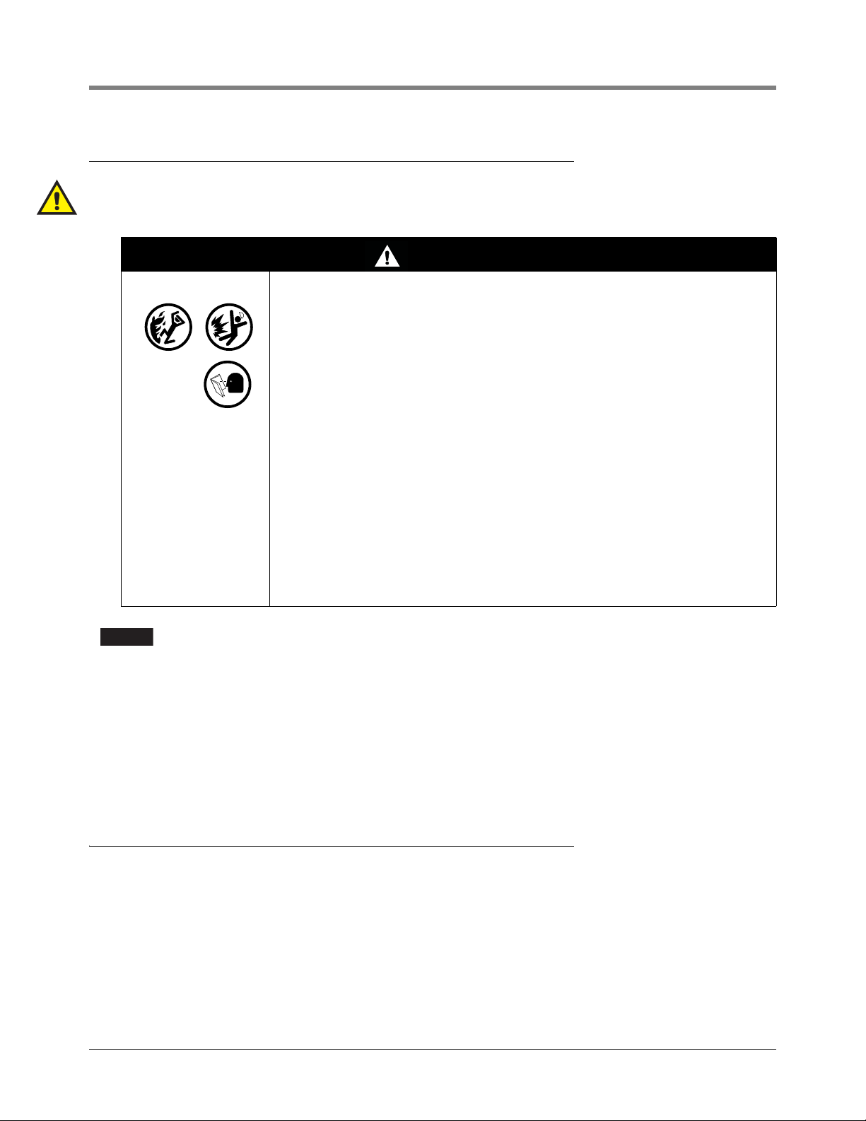
Safety Warnings
Who is allowed to work on this equipment: Only trained or authorized individuals knowledgeable in
the related procedures should install, inspect, maintain, or service this equipment.
WARNING
This system operates near highly combustible fuel storage tanks.
FAILURE TO COMPLY WITH THE FOLLOWING WARNINGS AND SAFETY
PRECAUTIONS COULD CAUSE DAMAGE TO PROPERTY, ENVIRONMENT,
RESULTING IN SERIOUS INJURY OR DEATH.
VEEDER-ROOT’S EMR4 PRODUCT IS NOT APPROVED FOR USE AS A
COMPONENT THAT PROVIDES LIQUID ADDITIVES TO AN AIRCRAFT FUELING
SYSTEM.
To ensure proper installation, operation, and continued safe use of this product:
1. Read and follow all instructions in this manual, including all safety
warnings.
2. Have equipment installed by a contractor trained in its proper installation
and in compliance with all applicable codes including: the National
Electrical Code; federal, state, and local codes; and other applicable safety
codes.
3. To prevent ignition of flammable or combustible atmospheres, disconnect
power before servicing.
4. Operate this equipment in accordance with the instructions in this manual.
5. Do not modify or use service parts other than those provided by VeederRoot. Substitution of components may impair intrinsic safety.
This system operates on low dc voltage/current inputs. To avoid equipment damage:
•
Dis
connect the EMR power wire prior to using vehicle battery charging equipment.
• Disconnect the EMR po
• Disconnect the EMR po
Always dis
•
If the storage tank to
connect the IB box from truck power before welding on the truck.
be fitted with an EMR4 system either contains or at any time has contained
wer wire prior to jump starting the vehicle.
wer wire prior to replacing the vehicle's battery.
petroleum products then the tank inspection chamber must be considered a hazardous environment
as defined in IEC EN 60079-10 Classification of Hazardous Areas. Suitable working practices for this
environment must be observed.
Special Conditions For Safe Use
All installations must be made in accordance with the accompanying Descriptive System Documentation.
2
Page 7
EMR4 Truck Installation
DC voltage from vehicle's accessory
circuit - at fuse block or ACC position
of ignition switch
Display Head 1
(Meter 1)
Meter 2
Remote Display Head 2
Top mount
Remote Pulser
Front mount
Remote Pulser
TRUCK CAB
OUTSIDE TRUCK CAB
Data (RS-485)
Data (RS-485)
Power
Data
Power 12 Vdc
Power 12 Vdc
5 Vdc
Pulse Input
NON-HAZARDOUS
LOCATION
(RS-232)
Printer
Quick disconnect
fittings (optional)
Temp
Probe
EPSON TM-U295 SLIP
Customer supplied wiring
The following information is for general reference and is not
intended to replace recommended National Electric Code (NEC)
procedures. It is important for the installer to understand that
wiring located in Class I, Group D, Division 1 and 2 installations,
or Class I, Zone 0, Group IIA locations shall comply with the latest
appropriate articles found in the National Electric Code (NFPA
70).
Check continuity between the Display Head chassis and the IB
chassis through the vehicle fra
me. The resistance must be no
more than 1 Ohm.
24 Vdc
Truck ground
Max. cable length
35 ft. (10.6 m)
Max. cable length
1000 ft. (304.8 m)
HAZARDOUS LOCATION
OR
I.S.
I.S.
I.S.
I.S.
I.S.
I.S.
NOTE: Intrinsically safe wiring
(marked ) shall be installed
in accordance with Article 504 of
the NEC, ANSI/NFPA 70.
Intrinsic
Safety Barrier
Interconnection
Box
12 AWG U.S. (4mm2 E.U.)
Barrier Ground
(See Notice 2)
Input Rating: 10-28 Vdc, 5 A
1.
See
Notice 2.
See
Notice 2.
2.
NOTICE
Interlock
Switch
I.S.
ESS
Switch
I.S.
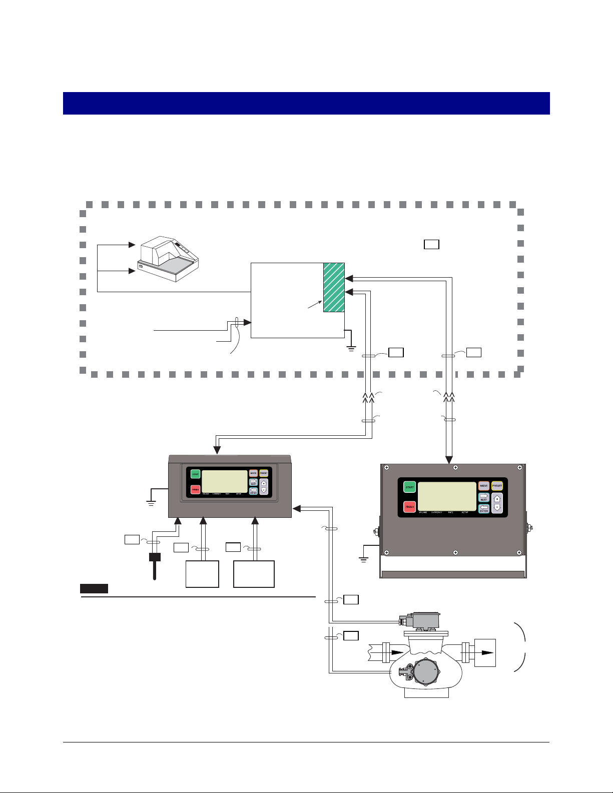
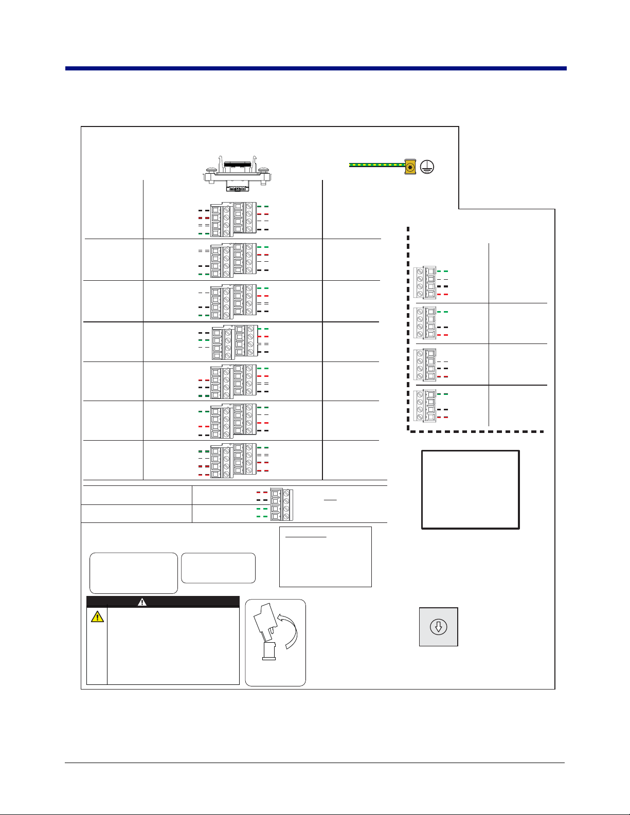
Installation of the EMR4 System involves installing the Display Head(s), the Interconnect Box, and any optional
devices (e.g., Remote Pulser, printer, etc.). This equipment must be installed according to the applicable
installation document. For UL/cUL installations use Control Drawing number 331940-021 and for ATEX
installations use Descriptive System Document number 331940-022. Figure 1 shows an example dual Display
Head installation.
Figure 1. Example EMR4 truck Installation With 2 Display Heads And Optional Remote Pulser
3
Page 8

EMR4 Truck Installation Installing The Interconnection Box (IB)
NOTICE
EMR3 - Truck Installations
Installing The Interconnection Box (IB)
The IB box is not rated for mounting in outdoor locations. The IB box can be mounted only
in a protected enclosure or protected location.
The following information is for general reference and is not intended to replace recommended National Electric
Code (NEC) procedures. It is important for the installer to understand that electrical equipment and wiring located
in Class I, Division 1 and 2 installations shall comply with the latest appropriate articles found in the National
Electric Code (NFPA 70) and other applicable code requirements.
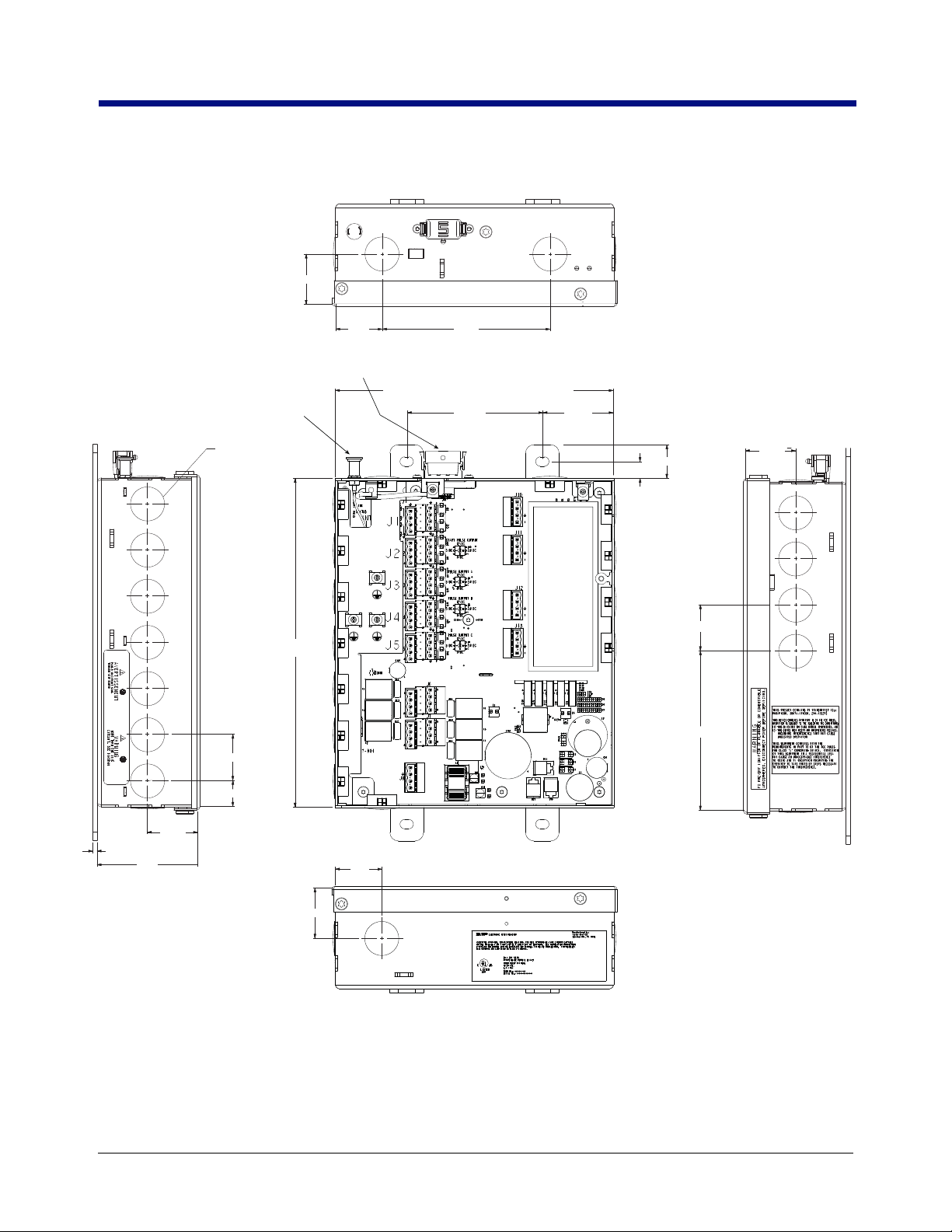
1. The physical dimensions of the Interconnection Box (IB) are shown in Figure 2.The IB is installed in the truck’s
cab either under the seat, mounted on the wall inside the cab, mounted to the passenger si
e” in cab-over trucks, or mounted to a custom-made bracket that can also suppor
hous
ur, 3/16” (4 mm) bolts to mount the IB to the mounting surface. In the event of limited access, the front
Use fo
cover of the IB can be completely removed rather than swung open, by removing four #15 Torx screws. Put
the excess coils of cable under the seat or clamp them to the IB mounting stand.
2. Figure 3 shows IB Power Side terminal wiring connections. Remove hole plugs and use
ables attaching to this terminal block.
c
he power cable from the truck fuse block or ignition switch to the IB. Clamp the power wire at suitable in-
Run t
tervals between the power source
fore connecting the truck power wiring, verify the following:
Be
and the IB.
de of the “dog
t the optional printer.
cord grips for all
ctrical system has a negative ground.
a. Ele
b. Bat
tery terminals and cables are in good condition.
c. Alternato
3. Attach the wire from truck ground to the GND terminal of the Power Side terminal block (J8, Pin 2).
attach the wire from the truck’s Accessory (ACC) circuit to the Input-Pwr terminal of the terminal block (J8-Pin
1).
4.
Refer to Figure 3 for the IB intrinsically safe terminal wiring connections. Remove hole plugs
ps for Display Head cable entries. The drain wire from the Display Head cable must be conne
gri
assis ground clamp in the Interconnect Box.
ch
r current output is sufficient to supply EMR4 System current requirement of 5 amperes.
Also
and use cord
cted to the
Input Power – Critical Ground Connection
On some vehicles, the battery minus terminal, BAT(-), may not be common with the chassis ground or the defined
vehicle ground located in either the accessory panel or in the power distribution box. In this case, directly run the
ground connection for Input Power at J8, Pin 2 (GND) terminal as shown in Figure 3, directly to the BAT(-) terminal
connection point.
Proper operation of the EMR4 hardware depends on the quality of the ground connection from the Interconnect
Box to the source of INPUT-PWR power.
If the INPUT-PWR connection is made at the accessory panel, it must be fused at 5 amps. The installer must
ensure that a minimum of 12.0 volts, between the INPUT-PWR terminal and the GND terminal, is available from
the power source. If an improper ground point is used for input power to the EMR4 there may be insufficient
power for the Display Head to operate properly resulting in various E## error codes or possibly a blank display.
Pay careful attention to the wiring labels on both the EMR4 Display Head and the Interconnect Box.
Each connection must be made according to the wiring tables listed in this manual. Use shielded
cable to connect each device to the Interconnect Box and Display Head and ensure that each cable
jacket is resistant to gas and oil.
4
Page 9

EMR4 Truck Installation Input Power – Critical Ground Connection
NOTICE
NOTICE
EMR3 - Truck Installations
Installations With High Amperage Devices
The input power for an EMR4 must be isolated from devices that use large amounts of electric current such as reel
motors. Connect the EMR4 using dedicated wiring between the voltage source and the Interconnect Box. On
vehicles with multiple voltage sources it may be necessary to use a separate battery or voltage source to power
the EMR4. Also, a battery isolator can be used between the voltage source and the IB to prevent voltage spikes
from entering the Interconnect Box when the high amperage devices are de-energized.
Recharging Vehicle Batteries
In the Interconnect Box, disconnect the wires for both the INPUT-PWR and GND Terminals while charging the
vehicle’s battery. Failure to do so can result in hardware damage to the circuit board inside the Interconnect Box.
5
Page 10
EMR4 Truck Installation Input Power – Critical Ground Connection
2X 1.5” (38mm)
1.39”
(35.3mm)
5.0”
(127mm)
7.8” (198mm) [8.5” (215.9mm) - w/cover in place]
4.04”
(103mm)
USB Port (under cover)
2.13”
(54.1mm)
0.5”
(12.7mm)
9.8”
(249mm)
1.0” (25.4mm)
SMA Connector
(under cover)
4X 1.5”
(38mm)
3X 1.375” (35mm)
4.75” (120.6mm)
REMOVE HOLE PLUG
FOR 1/2” (12.7mm)
CONDUIT OPENING
6X 1.375”
0.775”
7X 1.5”
(38MM)
3.0”
(72mm)
0.125” (3.1mm)
1.39”
(35.3mm)
1.5” (38mm)
EMR3 - Truck Installations
Figure 2. IB Physical Dimensions (Shown With Cover Removed)
6
Page 11
EMR4 Truck Installation Input Power – Critical Ground Connection
J1
J2
J3
J4
J5
J6
J7
J8
FUNCTION
FUNCTION
SIGNAL (COLOR)
SIGNAL (COLOR)
START PULSE OUTPUT 1
START PULSE OUTPUT 2
PULSE OUTPUT 1-A
PULSE OUTPUT 2-A
PULSE OUTPUT 1-B
PULSE OUTPUT 2-B
SERIAL 232 PORT 2
SERIAL 232 PORT 1
PULSE OUTPUT 1-C
PULSE OUTPUT 2-C
PRINTER PORT
(+24V OUT, SERIAL
RS-232 PORT)
RELAY 3 FOR
DISPLAY HEAD 1
RELAY 2 FOR
DISPLAY HEAD 1
RELAY 3 FOR
DISPLAY HEAD 2
RELAY 2 FOR
DISPLAY HEAD 2
RELAY 1 FOR
DISPLAY HEAD 1
RELAY PWR
RELAY 1 FOR
DISPLAY HEAD 2
RELAY PWR
NOTE: INPUT POWER
WIRING MUST USE
DEDICATED WIRES
BETWEEN THE POWER
SOURCE AND THE I.B.
INTERCONNECT BOX WIRING DIAGRAM
INTRINSICALLY SAFE WIRING
FUNCTION
SIGNAL (COLOR)
J10
(FACTORY SETTING)
*VOLTAGE SELECTABLE
RO
TARY SWITCH
*VOLTAGE SELECTABLE
*VOLTAGE SELECTABLE
*VOLTAGE SELECTABLE
*VOLTAGE SELECTABLE
RELAY RATINGS:
5A@120VAC
2.5A@240VAC
24VDC, 5A MAX.
J14
USB
5
6
7
8
5
6
7
8
1
2
3
4
5
6
7
8
1
2
3
4
5
6
7
8
1
2
3
4
5
6
7
8
1
2
3
4
1
2
3
4
1
2
3
4
5
6
7
8
1
2
3
4
5
6
7
8
1
2
3
4
GND (BLK)
DH2-RSTOP (RED)
DH2-RSTART (WHT)
GND (GRN)
GND (GRN)
DH1-RSTOP (RED)
DH1-RSTART (WHT)
GND (BLK)
REMOTE STOP INPUT 2
REMOTE START INPUT 2
REMOTE STOP INPUT 1
REMOTE START INPUT 1
GND (WHT)
TX (BLK)
RX (GRN)
GND (GRN)
DH1-SPULSE (RED)
DH2-SPULSE (WHT)
GND (BLK)
GND (WHT)
TX (BLK)
RX (GRN)
GND (GRN)
DH1-POUT-A (RED)
DH2-POUT-A (WHT)
GND (BLK)
HALF-DUPLEX RS-485
GND (BLK)
IBNET-A (GRN)
IBNET-B (WHT)
GND (GRN)
DH1-POUT-B (RED)
DH2-POUT-B (WHT)
GND (BLK)
GND (WHT)
+24V (RED)
PRN-TX (BLK)
PRN-RX (GRN)
GND (GRN)
DH1-POUT-C (RED)
DH2-POUT-C (WHT)
GND (BLK)
DH2-R3-NO (GRN)
DH2-R3-COM (WHT)
DH2-R2-NO (RED)
DH2-R2-COM (BLK)
DH1-R3-NO (GRN)
DH1-R3-COM (WHT)
DH1-R2-NO (RED)
DH1-R2-COM (BLK)
DH1-R1-NO (GRN)
DH1-R1-COM (WHT)
INPUT-PWR (RED)
INPUT-PWR (RED)
DH2-R1-NO (GRN)
DH2-R1-COM (WHT)
INPUT-PWR (RED)
INPUT-PWR (RED)
INPUT-PWR (RED)
GND (BLK)
IB-A (GRN)
IB-B (WHT)
GND (BLK)
PWR 12V (RED)
PWR 5V (GRN)
DATA (WHT)
GND (BLK)
PWR 12V (RED)
DATA (WHT)
GND (BLK)
PWR 12V (RED)
4
3
2
1
IB-A (GRN)
IB-B (WHT)
GND (BLK)
PWR 12V (RED)
4
3
2
1
4
3
2
1
4
3
2
1
DISPLAY HEAD 1
(I.S. PROTECTED)
DISPLAY HEAD 2
(I.S. PROTECTED)
AUX 1
(I.S. PROTECTED)
AUX 2
(I.S. PROTECTED)
5VDC 24VDC
12VDC
0VDC
1
3
2
0
J13
J12
J11
CONNECTORS MAY
BE UNPLUGGED FOR
FIELD WIRING
WARNING
This system operates on low DC voltage/current
inputs.To avoid equipment damage, disconnect
the EMR4 input power plug (J8) prior to
performing ANY of the following truck maintenance issues:
• Using vehic
le battery charging equipment
• Jump starting the vehicle
• Replacing the vehic
le’s battery
• Welding on the truck
12/24V INPUT
FOR USE WITH PERIPHERAL
EQUIPMENT SPECIFIED IN THE
INSTALLATION INSTRUCTIONS.
LED INDICATORS
COMM (D10) : EMR4 STATUS
STATUS (D12) : WIFI STATUS
LINK (D15) : WIFI LINK INDICATION
SEE MANUAL FOR DETAILS
FOR SUPPLY CONNECTION,
USE WIRES RATED FOR A
MINIMUM OF 90°C.
CHASSIS-GND (GRN)
CHASSIS-GND (GRN)
TRUCK BATTERY / TERMINAL UPS:
10-28VDC, 5A MAX.
RELAY GROUND
BARRIER GROUND WIRE
EMR3 - Truck Installations
Figure 3. EMR4 IB Box Wiring Connections
7
Page 12
EMR4 Truck Installation Input Power – Critical Ground Connection
DH 1
Relays
C
N.O.
Single
Flow
C
N.O.
Fast
Flow
DH 2
Relays
C
N.O.
Single
Flow
C
N.O.
Fast
Flow
EMR3 - Truck Installations
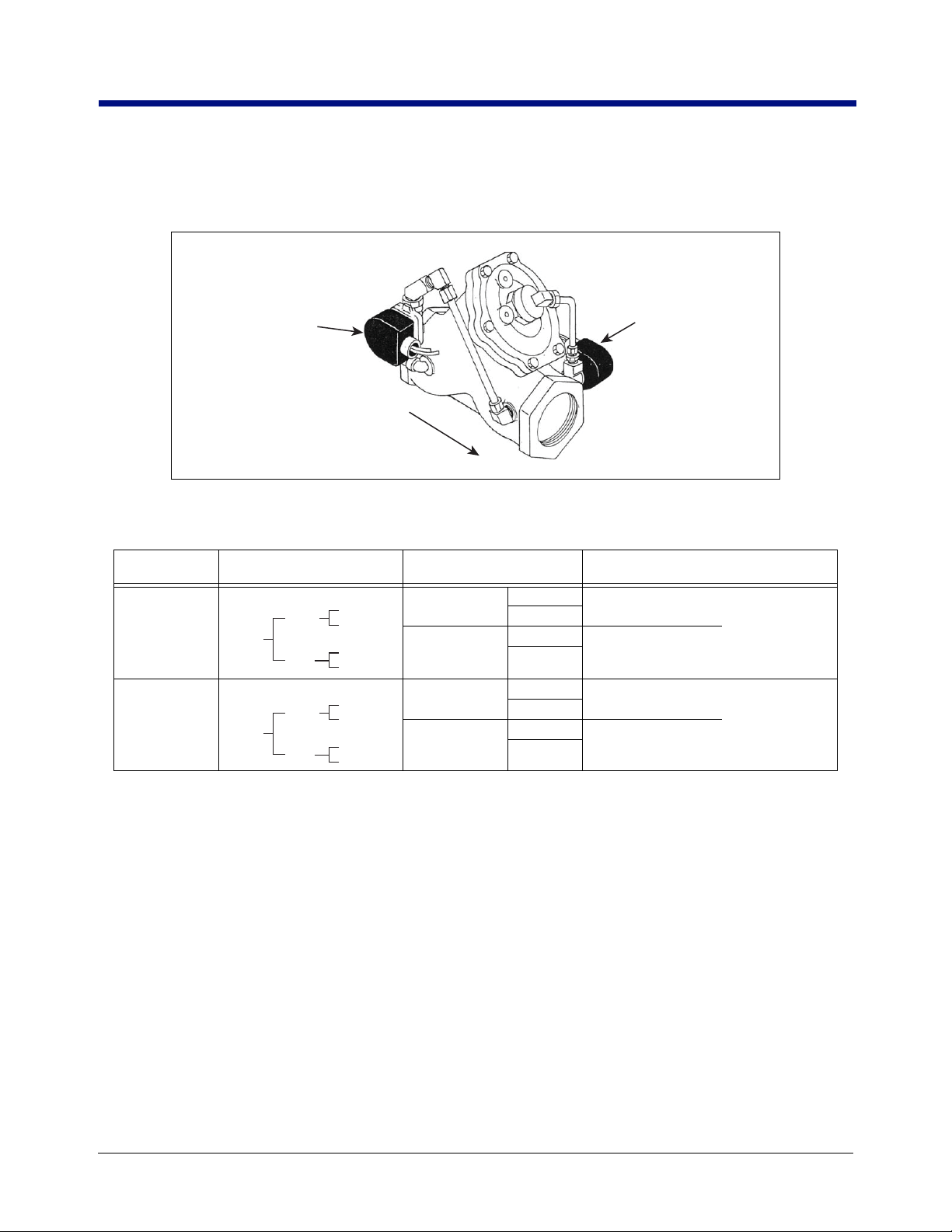
2-STAGE SOLENOID VALVE CONNECTIONS
A 2-stage solenoid flow valve is shown in Figure 4 and wiring connections in Table 1.
Single Flow In IB
(Relay 2)
(Solenoid Valve
Number Begins
With 7221)
Display Head Relay Function
Head 1
Head 2
Flow
Figure 4. 2-Stage Solenoid Valve
Table 1. 2-Stage Solenoid Wiring
Diagram In
Installation Manual Setup Manual
DH1-R2
DH1-R1
DH2-R2
DH2-R1
COM
N.O.
COM
N.O.
COM
N.O.
COM
N.O.
Fast Flow In IB
(Relay 1)
(Solenoid Valve
Number Begins
With 7121)
Relay Control
Set Advance Stop
Relay Control
Set Slow Flow
Relay Control
Set Advance Stop
Relay Control
Set Slow Flow
(2nd Stage
Knockoff)
(1st Stage
Knockoff)
(2nd Stage
Knockoff)
(1st Stage
Knockoff)
VALVE OPERATION WITH THE EMR4
Full Flow
The valve is normally closed. When the START button is pushed on the EMR4 display, both relays for that head are
energized, opening the solenoid-operated valves. The Fast Flow solenoid valve allows the main valve diaphragm to
open via the pump pressure pushing on the diaphragm. Full flow is obtained. The Slow Flow solenoid valve allows
flow around the main diaphragm valve. When the FINISH button is pushed on the EMR4 display, both relays are
de-energized, the solenoid valves close stopping flow.
Preset
The valve is normally closed. When the START button is pushed on the EMR4 display, both relays for that head are
energized, opening the solenoid valves and fast/full flow is obtained.
• First Stage Knockoff - When the first stage/slow flow point is reached (1st stage knockoff), the fast flow/relay
de-en
ergizes and the spring assisted main diaphragm of the valve closes as the pressure equalizes. The si
y 2 bypass remains open for slow flow.
8
flow/rela
1
ngle
Page 13

EMR4 Truck Installation 3-Way Safety Valve for Truck LP Gas Systems
NOTICE
EMR3 - Truck Installations
• Second Stage Knockoff - When the advance stop (2nd stage knockoff) point is reached, the single flow/relay 2
ergizes and the single flow/bypass valve closes stopping flow.
de-en
nockoff Control Adjustments - The ‘volume to go’ adjustments are made under RELAY CONTROL in setup
K
mode. The 1st stage defaults to 5 and the 2nd stage defaults to 0.1. Adjustments to these knockoff points,
particularly the 2nd stage/stop point may be required to accommodate the specific systems dynamics.
3-Way Safety Valve For Truck LP Gas Systems
The 3-Way Safety Valve is not intended for flow control or preset control.
WARNING
The Three-Way Safety Valve is installed and operated in the highly
combustible environment of an LPG tank.
FAILURE TO COMPLY WITH THE FOLLOWING WARNINGS AND SAFETY
PRECAUTIONS COULD CAUSE DAMAGE TO PROPERTY, ENVIRONMENT,
RESULTING IN SERIOUS INJURY OR DEATH.
1. It is essential that you carefully read and follow the warnings and
instructions in this manual to protect yourself and others from serious
injury due to fire, explosion, or electrical shock. LPG systems shall be
installed in accordance with the national standards and regulations that
apply.
2. Comply with all federal, state, and local codes, and other applicable
safety codes. All wiring must comply with standard electrical practices,
the local authority, and the latest editions of the National Electrical Code
(NFPA 70) and other applicable code requirements. All work on LPG
systems must comply with NFPA 58, Liquefied Petroleum Gas Code and
other applicable code requirements.
3. LPG tanks must be depressurized (drained) and free of liquid and
combustible vapors before work begins.
4. Flow control valves connected to the EMR4 must be UL Listed. Also, flow
control valves must be suitable for the intended application, i.e.,
gasoline, fuel oil, LPG and must be rated for use in a Class 1, Division 1,
Group C or Group D Hazardous Location. For LPG applications, such as
propane, each valve must have a minimum pressure rating of 350 psi.
INSTALLING THE 3-WAY VALVE
On the male pipe threads, use a pipe sealant when installing fittings or conduit to either
the valve or the junction box.
1. On the valve, install a rigid metal conduit nipple in the threaded opening, provided for the solenoid wiring. Run
the two red wires from the 3-way valve, through the nipple and into a metal junction box. Mechanically attach
the valve/nipple combination to junction box as shown in Figure 5. Even though the 3-way valve will operate
in any position, it will last longer and perform best if mounted vertically upright (port 3 up). Secure the
junction box to the vehicle's frame.
2. Run a 2-wire shielded cable from the Relay Terminals located at J7 in the IB Box, located in the truck cab, to
the 3-way valve junction box. Pass the cable through a cord grip fitting in one of the J-box openings. Cut off 1inch (25.4 mm) of the cable’s shield and jacket, then strip off 1/2-inch (12.7 mm) of each wire’s insulation.
9
Page 14

EMR4 Truck Installation 3-Way Safety Valve for Truck LP Gas Systems
Rigid Metal
Junction Box
Shrink wrapped diode
Shielded 2-Wire Cable
V-R PN 848100-250
Cord Grip
V-R PN 331028-001
Port 1
(N.C.)
Port 3
(N.O.)
Port 2
(COM)
Hose Connections
are 1/4'' NPT
Connect to Line
Pressure
Connect to
Differential
Valve
12 Vdc 10 Watts
3-Way Solenoid Valve
Connect to
Air Eliminator
Connect wires
in IB unit
1/2'' NPT
Nipple or Conduit
758-23.eps
Black
White (+)
To
3-Way
valve
To
IB unit
Red
Red
Wire nuts
Instructions:
NOTE: When temperature is below 50°F (10°C), keep
resin in a warm place prior to mixing (e.g., in an inside
pocket next to body).
1. Attach red wires from 3-way valve to black and white
(+) wire from IB unit with wire nuts as shown in A.
Connect diode white wire to red/white (+) pair.
Connect diode black wire to red/black pair.
2. Open epoxy package, and remove resin pak.
3
. Holding
resin pak as shown in B, bend pak along long
length.
4. As shown in C, firmly squeeze the RED S
IDE of the
resin,
forcing it through the center seal and into
BLACK SIDE.
5.
Mix
thoroughly to a uniform color by squeezing
contents back and forth 25-30 times.
6. Squeeze mixed, warm resin into one end of bag and
cutoff other end.
7. Slowly insert wiring connections into sealing pack until
they fit snugly against the opposite end.
8
. Twist open end of bag and use tie wrap to close it off,
or wrap open end of bag with vinyl electrical tape (not
included) and position the taped end up until the resin
jells.
9. P
lace epoxy pack into junction box and screw on
cover as shown in D.
C
A
D
B
Diode
(+)
EMR3 - Truck Installations
3. Using the wire nuts, connect the stripped wires from the IB box to the 3-way valve wires (see Figure 5). There
s no polarity to the 3-way valve’s wiring. Seal the wire nuts with epoxy sealant using one bag for both wire nu
i
conn
ections and place bag in junction box (see Figure 5).
t
CAUTION
Epoxy sealant is irritating to eyes, respiratory system, and skin. Can cause allergic skin
reaction. Contains: epoxy resin and cycloaliphatic epoxycarboxylate. Precautions: Wear
suitable protective clothing, gloves, eye, and face protection. Use only in well ventilated
areas. Wash thoroughly before eating, drinking, or smoking.
Figure 5. Connecting 3-Way Valve To Neptune Meter - Truck LP Gas Installations
4. Tighten the cable bushing nuts on the cord grip to ensure a watertight seal at the cable’s entry.
5. Remove the protective closures from the 3-way valv
Neptune
Connec
sy
stems, line pressure is available at an opening in the vapor eliminator housing. Connect another hose
he 3-way valve’s port 1 (normally closed port) to the air eliminator. Connect a third hose from the 3-
t
valve’s port 2 (co
L.C./TCS Mete
Connect a hose from the air eliminator to port 3 (normally open port) of the 3-way valve (see Figure 6). Con-
meters:
t a hose from line pressure to port 3 (normally open port) of the 3-way valve (see Figure
mmon port) to the differential valve.
rs:
nect another hose from the 3-way valve’s port 1 (normally closed port) to the strainer cover. Connect a third
hose from the 3-way valve’s port 2 (common port) to the differential valve.
e ports.
10
5). On some
from
way
Page 15

EMR4 Truck Installation 3-Way Safety Valve for Truck LP Gas Systems
EMR3 - Truck Installations
758-24.eps
Hose Connections
are 1/4'' NPT
Port 3
(N.O.)
Connect to Air
Eliminator
A
To
3-Way
valve
Port 2
(COM)
Red
Red
Port 1
(N.C.)
Wire nuts
White (+)
Diode
1/2'' NPT
Nipple or Conduit
12 Vdc 10 Watts
3-Way Solenoid Valve
Black
To
IB unit
Connect to
Strainer
Cover
Rigid Metal
Junction Box
Connect to
Differential
Valve
B
(+)
Shielded 2-Wire Cable
V-R PN 848100-250
Cord Grip
V-R PN 331028-001
Shrink wrapped diode
Connect wires
in IB unit
D
Instructions:
NOTE: When temperature is below 50°F (10°C), keep
resin in a warm place prior to mixing (e.g., in an inside
pocket next to body).
1. Attach red wires from 3-way valve to black and white
(+) wire from IB unit with wire nuts as shown in A.
Connect diode white wire to red/white (+) pair.
Connect diode black wire to red/black pa
Open epoxy package, and remove resin pak.
2.
. Holding
3
4. As shown in C, firmly squeeze the RED S
5.
6. Squeeze mixed, warm resin into one end of bag and
7. Slowly insert wiring connections into sealing pack until
8
. Twist open end of bag and use tie wrap to close it off,
9.
resin pak as shown in B, bend pak along long
length.
resin,
forcing it through the center seal and into
BLACK SIDE.
Mix
thoroughly to a uniform color by squeezing
contents back and forth 25-30 times.
cutoff other end.
they fit snugly against the opposite end.
or wrap open end of bag with vinyl electrical tape (not
included) and position the taped end up until the resin
jells.
Place epoxy pack into junction box and s
cover as shown in D.
ir.
C
IDE of the
crew on
Figure 6. Connecting 3-Way Valve To L.C./TCS Meter - Truck LP Gas Installations
6. At the IB Box, connect the 3-way valve solenoid and a jumper to J7 and J8 as shown in Figure 7.
11
Page 16

EMR4 Truck Installation 3-Way Safety Valve for Truck LP Gas Systems
Wire nut
Red
Red
Black
Black
White
White
Wire nut
3-Way Valve
Solenoid
Cord
Gr
ip
Nipple
J-Box
Suppression Diodes can only be
used with DC powered solenoids.
Suppressor diode
V/R Kit P/N 846000-022
Suppressor Diode Ratings:
Output Current of 1.0 Amp,
Maximum reverse voltage 420 Volts
Interconnect Box
Power-Side Terminals
J7
J8
DH1-R1-NO
DH1-R1-COM
INPUT-PWR
INPUT-PWR
DH2-R1-NO
DH2-R1-COM
INPUT-PWR
INPUT-PWR
INPUT-PWR
GND
CHASSIS-GND
CHASSIS-GND
Note: Use either INPUT-PWR terminal
to provide power to valve
Note: Use either CHASSIS-GND terminal
to provide return for valve
Note: Use DH2-R1-NO and DH2-R1-COM
if using Display Head 2 to control valve
NOTICE
EMR3 - Truck Installations
SOLENOID VALVES
Figure 8 illustrates wiring examples when connecting DC or AC solenoid valves to the IB box.
Figure 7. Connecting 3-Way Valve To The Interconnect Box
12
Page 17

EMR4 Truck Installation 3-Way Safety Valve for Truck LP Gas Systems
DC Solenoid
valve
Rigid conduit
Seal off
J-Box
Rigid
conduit
L
N
Supply
120/240 Vac
1
Interconnect Box
Power Side terminals
AC Solenoid
valve
Rigid conduit
Sealoff
AC Solenoid Wiring
DC Solenoid Wiring
Wire nut
Red
Red
Black
Black
White
White
Wire nut
Suppressor diode
V/R Kit P/N 846000-022
Suppressor Diode Ratings:
Output Current of 1.0 Amp,
Maximum reverse voltage 420 Volts
Suppression Diodes can only be
used with DC powered solenoids.
Interconnect Box
Power-Side Terminals
J7
J8
DH1-R1-NO
DH1-R1-COM
INPUT-PWR
INPUT-PWR
DH2-R1-NO
DH2-R1-COM
INPUT-PWR
INPUT-PWR
INPUT-PWR
GND
CHASSIS-GND
CHASSIS-GND
Note: Use either INPUT-PWR terminal
to provide power to valve
Note: Use either CHASSIS-GND terminal
to provide return for valve
Note: Use DH2-R1-NO and DH2-R1-COM
if using Display Head 2 to control valve
Note: Use DH2-R1-NO and DH2-R1-COM
if using Display Head 2 to control valve
J7
DH1-R1-NO
DH1-R1-COM
INPUT-PWR
INPUT-PWR
DH2-R1-NO
DH2-R1-COM
INPUT-PWR
INPUT-PWR
NOTICE
EMR3 - Truck Installations
Figure 8. Example Wiring Connections For DC And AC Solenoid Valves
13
Page 18

EMR4 Truck Installation Wiring The Display Head
EMR3 - Truck Installations
Wiring The Display Head
1. With the Display Head cover still off, remove the nut and bushing from the top side panel cord grip connector.
: the maximum cable length between the Interconnect Box and the Display Head is 1000 fe
Note
m
eters).
2. Slide the cord grip nut and then the bushing over the IB cable leads. Pull enough cable through so that the
leads reach the terminal block on the display assembly and can be tie wrapped to the pulse encoder mounting
base as shown in Figure 9. Slide the tapered end of the bushing into the cord grip, then screw on t
gri
p nut and tighten securely.
et (304.8
he cord
3. Attach the four-wire IB cable to the terminal block where shown in Figure 9. Attach the drain wire of t
cabl
e to a grounding lug on the Pulse Encoder mounting base.
When
stripping wire for terminal block connections, be careful not to nick the individual strands. Also, be su
o tighten each terminal so the wire can not be pulled out. A failure to follow either of these instructions can re-
t
sult in signal loss and faulty operation.
4. If you have the optional temperature probe and/or ESS switch, remove the lower cord grip nut and slide it
t
hen the tapered bushing, over the temperature probe and/or ESS switch cable. Pull enough cable through
hat the leads reach the terminal block on the display assembly and can be tie wrapped to the pulse e
t
mou
nting base as shown in Figure 9. Slide the bushing into the cord grip and then screw the cord grip nu
onto th
e cord grip and tighten securely. Attach the shield of the temperature probe cable and/or ESS swit
e to a grounding lug on the pulse encoder mounting base.
cabl
5. Attach each wire (no polarity) of the 2-conductor temperature probe and/or ESS switch cable(s) where shown
on the terminal block la
Tie wrap the IB, ESS switch, and temp probe (if installed) cables to the Pulse Encoder mounting base.
6.
7. For transfer Interlock applications, attach the two wires in the switch cable where shown on the terminal bl
l
abel and tie wrap the cable to the pulse encoder’s mounting base.
8. Replace the Display Head cover and screw in the four cover retaining bolts just enough to hold them in (t
c
over will be removed later for system calibration).
9. Using the tie wraps from the installation kit, attach the 4-wire cable from the Display Head to the Interconne
Box along
arp bends and placements where vibration might wear through the cable. Allow ample cable length
sh
compens
rough a split loom or tubing will offer added protection from weather and abrasion. Use a rubber grom
th
cord gri
require detachable plugs, and either a separate tensioning device much like that used to protect air lines
perhaps attach
the inside of the truck frame, to existing piping, or to the reel motor cable back to the cab. Avoi
ate for tilt-cab trucks and to avoid putting additional stress on the assembly. Running the cabl
p to line the hole where cable passes through truck cab wall or floor. Tractor-trailer installations will
the cable to one of the existing air lines with tie wraps.
bel.
he IB
re
,
so
ncoder
t
ch
ock
he
ct
d
to
e
met or
, or
10. Check continuity between the Display Head chassis and IB chassis through the vehicle frame. This resistan
must
be less than 1 ohm.
14
ce
Page 19

EMR4 Truck Installation Wiring The Display Head
ENS1J-489ENS1J-489
-L00100 -L00100
BOURNSBOURNS
VR ENCODERVRENCODER
P/N P/N
331884-001331884-001
331933-001331933-001
I.S.I.S.
Intrinsically-safe inputs from
Interconnect Box, emergency stop switch,
interlock switch, temperature probe,
and optional series 8452 remote pulser
Route cables as shown to
avoid interference with flexible
encoder shaft. Use tie wraps
to attach cables to base.
Pulse encoder
Optional keypad
Encoder shaft
spring
C&C
Jumper
Display head
terminal block
Attach optional remote
pulser, temperature probe,
interlock switch, IB cable and
ESS switch cable shields to
grounding lug on base.
9/64” (3.5mm) max.
Note: Maximum screwdriver
size for attaching wires to
terminal block.
C&C Switch - Removal of corner
bolt releases actuator lever of C&C
switch allowing entry into C&C Mode
#6 Self tapping
screws (3)
Rubber gasket (1)
INTERCONNECT BOX 1000 RPM ENCODER
OPTIONAL KEYPAD
TEMP PRB
INTERLOCK
STOP SWC & C SW
BLK
GND
RED
PWR
YEL+YEL
GND
WHT+BLK
GND
GRN
CHA
WHT
CHB
BLK
GND
RED
+5V
WHT
+
BLK
GND
WHT+BLK
GND
ORA
KP8
BLU
KP7
YEL
KP6
GRN
KP5
WHT
KP4
BLK
KP3
RED
KP2
NOT
USED
GRN
IB-A
WHT
IB-B
EMR3 - Truck Installations
Figure 9. Display Head Cable Connections
15
Page 20

EMR4 Truck Installation C&C Mode Switch
EMR3 - Truck Installations
C&C Mode Switch
The C&C corner switch assembly (P/N 845900-018) that fits into one corner of the Display Head’s housing (see
Figure9). To enter C&C mode, remove the corner bolt from the Display Head’s cover. To exit C&C mode, replace
the bolt. When using the corner switch, remove the C&C jumper.
Installing Optional Keypad Kit - Right Or Left Side
Figure9 shows the installation and wiring of the optional keypad. To attach the keypad housing mounting screws,
you will need to pull/slide up the display assembly away from the Display Head. Insert the keypad wires through
the center hole in the gasket, slide the gasket down against the keypad and align its three holes with the mounting
holes in the keypad. Hold the keypad against the Display Head and screw in the 3 mounting screws, replace the
display assembly and then connect the keypad wiring to the terminal block as shown in Figure9. The screws are
self-tapping. The user may want to pre-tap the holes using the screw to ease installation.
Installing The Remote Display (Optional)
The Remote Display consists of the items listed in Table 2:
Table 2. Remote Display (84559X-00X) Components
Description V-R P/N
Remote Display install kit 330020-430
Opt. Mounting Bracket kit 845900-024
Opt. 4 conductor cable - 6 ft (1.83 m) 846000-107
Opt. 4 conductor cable - 35 ft (10.67 m) 846000-106
Opt. 4 conductor cable - 50 ft (15.24 m) 846000-100
Opt. 4 conductor cable - 100 ft (30.48 m) 846000-101
Opt. 4 conductor cable - 200 ft (60.96 m) 846000-102
Opt. 4 conductor cable - 300 ft (91.44 m) 846000-103
Opt. 4 conductor cable - 400 ft (121.92 m) 846000-104
Opt. 4 conductor cable - 500 ft (152.4 m) 846000-105
Figure 10 shows the Remote Display assembly and Figure 11 shows how to wire the display to the Interconnect
Box. You can mount the display on a wall or dashboard of a truck, a wall in a building, or outside in a hazardous
location. Use appropriate fasteners in any of the pre-drilled holes in the base of the optional bracket when
attaching the bracket to the mounting surface. Adjust the angle of the display by loosening the side bolts and
rotating the unit to the desired position.
Following wiring routing precautions and procedures discussed earlier (page 14) for the meter mounted Display
Head, connect the Remote Display to the Interconnect Box. Wiring connections at the Remote Display are shown
in Figure 11. Install optional cord grip fitting in rear of Remote Display for cable egress. Wiring connections at the
IB are to the identical terminals of the unused Display Head terminal block.
16
Page 21

EMR4 Truck Installation IInstalling The Remote Display (Optional)
Front View Rear View
Mounting bracket kit
(P/N 845900-024)
Plastic caps (remove
for cable entry)
These 2 hex head bolts are drilled
through for sealing the front cover
C&C switch
#30 Torx screws (4)
758-27.eps
#30 Torx screws (4) fasten into back of
Remote Display housing
Adjust mounting strips to desired
indents each side, then tighten nuts
Mounting Strips shown
in low position (2)
1 Nut and 1 lockwasher
each side
Base
Mounting Strips
shown in high
position
Assembly of Remote Display
Head Mounting Bracket
Side view
8.625"
(220 mm)
high position
or
6.625"
(168 mm)
low position
9.5"
(240 mm)
3.25"
(83 mm)
5.625"
(143 mm)
Remote Display Head
(P/N 84559X-002)
EMR3 - Truck Installations
Figure 10. Remote Display Assembly
Figure 11 displays the wiring connections to a remote display.
17
Page 22

EMR4 Truck Installation IInstalling The Remote Display (Optional)
Rear cover of
Remote Display
Front panel
C&C switch
Remote Display
terminal block
Remove a plastic cap from one
of the rear access ports to install
input cable(s)
Cord grip
Nut
To external device
9/64” (3.5 mm) max.
To terminal
block
Bushing
Remote Display (rear cover removed)
Cable entries to Remote Display
Attaching wires to
terminal block
GRN
IB-A
INTERCONNECT BOX
1000 RPM ENCODER OPTIONAL KEYPADTEMP PRBINTERLOCK
STOP SWC & C SW
BLK
GND
WHT
IB-B
RED
PWR
YEL+YEL
GND
WHT+BLK
GND
GRN
CHA
WHT
CHB
BLK
GND
RED
+5V
WHT
+
BLK
GND
WHT+BLK
GND
ORA
KP8
BLU
KP7
YEL
KP6
GRN
KP5
WHT
KP4
BLK
KP3
RED
KP2
NOT
USED
Note: Maximum screwdriver
size for attaching wires to
terminal block.
EMR3 - Truck Installations
Figure 11. Remote Display Connections (Rear Cover Removed)
18
Page 23

EMR4 Truck Installation Installing The Remote Pulser (Optional)
758-30.eps
+V
GND
CHB
CHA
Cable to
Display
Head
EMR3 - Truck Installations
Installing The Remote Pulser (Optional)
The EMR4 remote pulser consists of a 5 Vdc optical encoder assembled into a stand-alone cast housing. The
Remote Pulser can be mounted to either the top or the front of the meter using one of two available kits. The
remote pulser operates under the same specifications as the existing internal pulse encoder. Refer to Veeder-Root
manual number 577014-355 for detailed pulser mounting instructions.
• The top mount kits (P/N 845900-504, 845900-552) contain the remote pulser
hardware.
The front mount kits (P/N 845900-505, 845900-506) contain the remote pulser
•
hardware
. The customer or end user will have to supply the mounting scheme to install the remote pulser to the
front of the meter.
.
Figure 12. Wiring Connections In Remote Pulser (Top Cover Removed)
, mounting plate and mounting
and limited mounting
PULSE ENCODER SPECIFICATIONS
Power: 5 Vdc, 30 mA +10%
Shaft Rotation: 1000 rpm maximum, bidirectional, 20 oz-in
Pulse: 100 ppr, Quadrature type
19
Page 24

EMR4 Terminal & Fueling Depot Installation
Installation of the EMR4 System involves installing the Display Head(s), installing the interconnect box, and
installing any optional devices (e.g., remote pulser, printer, etc.). This equipment must be installed according to the
applicable installation document. For UL/cUL installations use Control Drawing number 331940-021 and for
ATEX installations use Descriptive System Document number 331940-022. Figure 13 shows an example dual
Display Head installation.
The following information is for general reference and is not intended
to replace recommended national electric code (nec) procedures. it is
important for the installer to understand that wiring located in Class I,
Group D Division 1 and 2 installations or Class I, Zone 0, Group IIA
locations shall comply with the latest appropriate articles found in the
National Electric Code (NFPA 70).
NOTICE
This is a control drawing only and does not reflect the actual
locations of conduit entry. In Installation and use of this product,
comply with the national electrical code; Federal, State and Local
Codes.
WARNING
FAILURE TO COMPLY WITH THE FOLLOWING
WARNINGS AND SAFETY PRECAUTIONS COULD CAUSE
DAMAGE TO PROPERTY, ENVIRONMENT, RESULTING IN
SERIOUS INJURY OR DEATH.
The Display Head must never be operated unless the front cover
and wiring shield are closed and properly sealed over the barrier
terminals in the intrinsically safe area of the Interconnect Box.
1. Intrinsically safe wiring (marked ) shall be installed in
accordance with Article 504 of the NEC, ANSI/NFPA 70.
2.
In the non-intrinsically safe compartment of the Interconnect Box,
connect the #12 AWG (4mm
ground lug.
3. To maintain intrinsic safety, display head to interconnect box
wiring must be run in dedicated conduit. Maximum cable length is
1,000 feet (304.8 M).
4. Display Head must be connected to earth ground
through its mounting screws.
I.S.
2
) or larger diameter barrier wire to a
Data
(RS-232)
Power
24 Vdc
120 or 240Vac
line cord
12 Vdc
Power
Supply
UL approved 120W
isolated secondary
Printer
EPSON TM-U220A ROLL
AC Power Protector
UPS
120 or 240Vac line
Input Rating: 10– 28 Vdc, 5 A
Customer supplied
wiring & rigid conduit
Connected to
Earth Ground
TERMINAL
OFFICE
NON-HAZARDOUS
LOCATION
Interconnect
Box
Intrinsic
Safety Barrier
12 AWG U.S. (4mm2 E.U.)
Barrier Ground
I.S.
I.S.
Power
Rigid conduit
Seal-off
Max. cable length
1000 ft. (304.8 m)
Data (RS-485)
Max. Remote
Pulser cable
length 35 ft.
(10.6 m)
Power
Data (RS-485)
Pulse Input
I.S.
I.S.
5 Vdc
Temp
Probe
Switch
Interlock
Switch
ESS
I.S.
I.S.
HAZARDOUS
LOCATION
Display Head 1
(Meter 1)
I.S.
Meter 1
Meter 2
Figure 13. Example Terminal Fueling Depot Installation With 2 Display Heads And Optional Remote Pulser
20
Remote
Display Head 2
Top mount
Remote Pulser
OR
Front mount
Remote Pulser
Page 25

EMR4 Terminal & Fueling Depot Installation Wiring The Display Head
EMR3 - Truck Installations
Wiring The Display Head
1. With the Display Head cover still off, remove the nut and bushing from the right side panel cord grip
connector. Note: the maximum cable length between the Interconnect Box and the Display Head is 1
(304.8
meters).
2. Slide the cord grip nut and then the bushing over the IB cable leads. Pull enough cable through so that the
leads reach the terminal block on the display assembly and can be tie wrapped to the pulse encoder mounting
base as shown in Figure 14. Slide the tapered end of the bushing into the cord grip, then screw on th
gri
p nut and tighten securely.
000 feet
e cord
3. Attach the four-wire IB cable to the terminal block as shown in Figure
stripping wire for terminal block connections, be careful not to nick the individual strands. Also, be su
When
t
o tighten each terminal so the wire can not be pulled out. A failure to follow either of these instructions can re-
sult in signal loss and faulty operation.
4. If you have the optional temperature probe and/or ESS switch, remove the lower cord grip nut and slide it,
hen the tapered bushing, over the temperature probe cable and/or ESS switch cable. Pull enough cable
t
through so that the leads reach the terminal block on the display assembly and can be tie wrapped to t
lse encoder mounting base as shown in Figure 14. Slide the bushing into the cord grip and then
pu
cord gri
groun
5. Attach each wire (no polarity) of the 2-connector temperature probe cable and/or ESS switch where sh
on th
6.
Tie wrap the IB, ESS switch and temp probe (if installed) cables to the pulse encoder mounting base.
7. For transfer Interlock applications, attach the two wires in the switch cable where shown on the terminal bl
abel and tie wrap the cable to the pulse encoder’s mounting base.
l
8. Replace the Display Head cover and screw in the four cover retaining bolts just enough to hold them in (the
c
p nut onto the cord grip and tighten securely. Attach the shield of the temperature probe cable to
ding lug on the Pulse Encoder mounting base.
e terminal block la
over will be removed later for system calibration).
bel.
14.
he
screw the
a
own
re
ock
21
Page 26

EMR4 Terminal & Fueling Depot Installation Installing The Interconnect Box (IB)
ENS1J-489ENS1J-489
-L00100 -L00100
BOURNSBOURNS
VR ENCODERVRENCODER
P/N P/N
331884-001331884-001
331933-001331933-001
I.S.I.S.
Intrinsically-safe inputs from
Interconnect Box, emergency stop switch,
interlock switch, temperature probe,
and optional series 8452 remote pulser
Route cables as shown to
avoid interference with flexible
encoder shaft. Use tie wraps
to attach cables to base.
Pulse encoder
Optional keypad
Encoder shaft
spring
C&C
Jumper
Display head
terminal block
Attach optional remote
pulser, temperature probe,
interlock switch, and
ESS switch cable shields to
grounding lug on base.
9/64” (3.5mm) max.
Note: Maximum screwdriver
size for attaching wires to
terminal block.
C&C Switch - Removal of corner
bolt releases actuator lever of C&C
switch allowing entry into C&C Mode
#6 Self tapping
screws (3)
Rubber gasket (1)
INTERCONNECT BOX 1000 RPM ENCODER
OPTIONAL KEYPAD
TEMP PRB
INTERLOCK
STOP SWC & C SW
BLK
GND
RED
PWR
YEL+YEL
GND
WHT+BLK
GND
GRN
CHA
WHT
CHB
BLK
GND
RED
+5V
WHT
+
BLK
GND
WHT+BLK
GND
ORA
KP8
BLU
KP7
YEL
KP6
GRN
KP5
WHT
KP4
BLK
KP3
RED
KP2
NOT
USED
GRN
IB-A
WHT
IB-B
EMR3 - Truck Installations
Installing The Interconnect Box (IB)
NATIONAL ELECTRICAL CODE COMPLIANCE
The following information is for general reference and is not intended to replace recommended National Electric
Code (NEC) procedures. It is important for the installer to understand that electrical equipment and wiring located
in Class I, Division 1 and 2 installations shall comply with the latest appropriate articles found in the National
Electric Code (NFPA 70) and the Automotive and Marine Service Station Code (NFPA 30A).
GROUNDING
Proper grounding of the EMR equipment is essential for several reasons. First, in a typical installation, grounding
prevents hazardous voltages from being present on the equipment. Secondly, grounding prevents the build-up of
static charge on the equipment. Either of these conditions could be very hazardous when in the proximity of
explosive mixtures found at fuel supply depots and terminals. Proper grounding requires that a very low impedance
connection be made to the earth. At the distribution panel, this is accomplished by means of a dedicated
conductor buried in the earth. It is imperative that all local, regional and national regulations are followed when
connecting to the grounding system.
Figure 14. Display Head Cable Connections
22
Page 27

EMR4 Terminal & Fueling Depot Installation Installing The Interconnect Box (IB)
NOTICE
NOTICE
NOTICE
EMR3 - Truck Installations
WIRE TYPE FOR METALLIC OR PVC CONDUIT
Veeder-Root requires the use of shielded cable when using metallic or PVC conduit in any portion of the wiring
between the Display Head and the IB. In these installations, shielded cable must be rated less than 100 picofarad
per foot and 0.2 microhenry per foot (per 304.8 mm) and be manufactured with a material suitable for the
environment.
Use either the 4-wire cable supplied by V-R, P/N 846000-1XX or any equivalent cable or wiring with rated
capacitance of less than 100 picofarads per foot (per 304.8 mm) and inductance of less than 0.2 microhenry per
foot (per 304.8mm). Note that conductor wire colors vary depending on the cable manufacturer (caution: the
Display Head to IB wiring illustrations in this section show wire colors in the V-R cable. Alternate cables may have
different wire colors).
Field wiring may be both above ground or below grade.
WIRE LENGTH
Improper system operation could result in undetected potential environmental and health hazards if the Display
Head to IB wire runs exceed 1000 feet (304.8 m). Wire runs must be less than 1000 feet to be within the limits of
the UL Certification.
MOUNTING AND WIRING THE IB UNIT
1. The physical dimensions of the Interconnect Box (IB) are shown in Figure 2 on page 6. The IB is installed in
he terminal - fueling depot office. Use four, 3/16” (4 mm) bolts to mount the IB to the mounting surface.
t
2. Figure 15 shows IB wiring connections. For IB Power Side terminal wiring connections, remove hole
and u
se cord grips for all cables attaching to this terminal bl
J10 and J11 terminal I.S. wiring connections, remove hole plugs and use cord grips for all cabl
For IB
att
aching to these terminal blocks. The drain wire from each Display Head cable must be connected to t
assis ground clamp in the IB I.S. area.
ch
ock.
plugs
es
he
3. The printer must be within 6 feet (1.83 m) of the IB box.
All field wiring entering the IB box should be run as straight as possible from the conduit
entry knockout to their designated terminal connectors.
SOLENOID VALVES
Figure 16 illustrates wiring examples when connecting dc or ac solenoid valves to the IB box.
The IB box is not rated for mounting in outdoor locations. The IB box can be mounted
only in a protected enclosure or protected location.
23
Page 28

EMR4 Terminal & Fueling Depot Installation Installing The Interconnect Box (IB)
J1
J2
J3
J4
J5
J6
J7
J8
FUNCTION
FUNCTION
SIGNAL (COLOR)
SIGNAL (COLOR)
START PULSE OUTPUT 1
START PULSE OUTPUT 2
PULSE OUTPUT 1-A
PULSE OUTPUT 2-A
PULSE OUTPUT 1-B
PULSE OUTPUT 2-B
SERIAL 232 PORT 2
SERIAL 232 PORT 1
PULSE OUTPUT 1-C
PULSE OUTPUT 2-C
PRINTER PORT
(+24V OUT, SERIAL
RS-232 PORT)
RELAY 3 FOR
DISPLAY HEAD 1
RELAY 2 FOR
DISPLAY HEAD 1
RELAY 3 FOR
DISPLAY HEAD 2
RELAY 2 FOR
DISPLAY HEAD 2
RELAY 1 FOR
DISPLAY HEAD 1
RELAY PWR
RELAY 1 FOR
DISPLAY HEAD 2
RELAY PWR
NOTE: INPUT POWER
WIRING MUST USE
DEDICATED WIRES
BETWEEN THE POWER
SOURCE AND THE I.B.
INTERCONNECT BOX WIRING DIAGRAM
INTRINSICALLY SAFE WIRING
FUNCTION
SIGNAL (COLOR)
J10
(FACTORY SETTING)
*VOLTAGE SELECTABLE
RO
TARY SWITCH
*VOLTAGE SELECTABLE
*VOLTAGE SELECTABLE
*VOLTAGE SELECTABLE
*VOLTAGE SELECTABLE
RELAY RATINGS:
5A@120VAC
2.5A@240VAC
24VDC, 5A MAX.
J14
USB
5
6
7
8
5
6
7
8
1
2
3
4
5
6
7
8
1
2
3
4
5
6
7
8
1
2
3
4
5
6
7
8
1
2
3
4
1
2
3
4
1
2
3
4
5
6
7
8
1
2
3
4
5
6
7
8
1
2
3
4
GND (BLK)
DH2-RSTOP (RED)
DH2-RSTART (WHT)
GND (GRN)
GND (GRN)
DH1-RSTOP (RED)
DH1-RSTART (WHT)
GND (BLK)
REMOTE STOP INPUT 2
REMOTE START INPUT 2
REMOTE STOP INPUT 1
REMOTE START INPUT 1
GND (WHT)
TX (BLK)
RX (GRN)
GND (GRN)
DH1-SPULSE (RED)
DH2-SPULSE (WHT)
GND (BLK)
GND (WHT)
TX (BLK)
RX (GRN)
GND (GRN)
DH1-POUT-A (RED)
DH2-POUT-A (WHT)
GND (BLK)
HALF-DUPLEX RS-485
GND (BLK)
IBNET-A (GRN)
IBNET-B (WHT)
GND (GRN)
DH1-POUT-B (RED)
DH2-POUT-B (WHT)
GND (BLK)
GND (WHT)
+24V (RED)
PRN-TX (BLK)
PRN-RX (GRN)
GND (GRN)
DH1-POUT-C (RED)
DH2-POUT-C (WHT)
GND (BLK)
DH2-R3-NO (GRN)
DH2-R3-COM (WHT)
DH2-R2-NO (RED)
DH2-R2-COM (BLK)
DH1-R3-NO (GRN)
DH1-R3-COM (WHT)
DH1-R2-NO (RED)
DH1-R2-COM (BLK)
DH1-R1-NO (GRN)
DH1-R1-COM (WHT)
INPUT-PWR (RED)
INPUT-PWR (RED)
DH2-R1-NO (GRN)
DH2-R1-COM (WHT)
INPUT-PWR (RED)
INPUT-PWR (RED)
INPUT-PWR (RED)
GND (BLK)
IB-A (GRN)
IB-B (WHT)
GND (BLK)
PWR 12V (RED)
PWR 5V (GRN)
DATA (WHT)
GND (BLK)
PWR 12V (RED)
DATA (WHT)
GND (BLK)
PWR 12V (RED)
4
3
2
1
IB-A (GRN)
IB-B (WHT)
GND (BLK)
PWR 12V (RED)
4
3
2
1
4
3
2
1
4
3
2
1
DISPLAY HEAD 1
(I.S. PROTECTED)
DISPLAY HEAD 2
(I.S. PROTECTED)
AUX 1
(I.S. PROTECTED)
AUX 2
(I.S. PROTECTED)
5VDC 24VDC
12VDC
0VDC
1
3
2
0
J13
J12
J11
CONNECTORS MAY
BE UNPLUGGED FOR
FIELD WIRING
WARNING
This system operates on low DC voltage/current
inputs.To avoid equipment damage, disconnect
the EMR4 input power plug (J8) prior to
performing ANY of the following truck maintenance issues:
• Using vehic
le battery charging equipment
• Jump starting the vehicle
• Replacing the vehic
le’s battery
• Welding on the truck
12/24V INPUT
FOR USE WITH PERIPHERAL
EQUIPMENT SPECIFIED IN THE
INSTALLATION INSTRUCTIONS.
LED INDICATORS
COMM (D10) : EMR4 STATUS
STATUS (D12) : WIFI STATUS
LINK (D15) : WIFI LINK INDICATION
SEE MANUAL FOR DETAILS
FOR SUPPLY CONNECTION,
USE WIRES RATED FOR A
MINIMUM OF 90°C.
CHASSIS-GND (GRN)
CHASSIS-GND (GRN)
TRUCK BATTERY / TERMINAL UPS:
10-28VDC, 5A MAX.
RELAY GROUND
BARRIER GROUND WIRE
EMR3 - Truck Installations
Figure 15. EMR4 IB Box Wiring Connections
24
Page 29

EMR4 Terminal & Fueling Depot Installation Installing The Interconnect Box (IB)
DC Solenoid
valve
Rigid conduit
Seal off
J-Box
Rigid
conduit
L
N
Supply
120/240 Vac
1
Interconnect Box
Power Side terminals
AC Solenoid
valve
Rigid conduit
Sealoff
AC Solenoid Wiring
DC Solenoid Wiring
Wire nut
Red
Red
Black
Black
White
White
Wire nut
Suppressor diode
V/R Kit P/N 846000-022
Suppressor Diode Ratings:
Output Current of 1.0 Amp,
Maximum reverse voltage 420 Volts
Suppression Diodes can only be
used with DC powered solenoids.
Interconnect Box
Power-Side Terminals
J7
J8
DH1-R1-NO
DH1-R1-COM
INPUT-PWR
INPUT-PWR
DH2-R1-NO
DH2-R1-COM
INPUT-PWR
INPUT-PWR
INPUT-PWR
GND
CHASSIS-GND
CHASSIS-GND
Note: Use either INPUT-PWR terminal
to provide power to valve
Note: Use either CHASSIS-GND terminal
to provide return for valve
Note: Use DH2-R1-NO and DH2-R1-COM
if using Display Head 2 to control valve
Note: Use DH2-R1-NO and DH2-R1-COM
if using Display Head 2 to control valve
J7
DH1-R1-NO
DH1-R1-COM
INPUT-PWR
INPUT-PWR
DH2-R1-NO
DH2-R1-COM
INPUT-PWR
INPUT-PWR
NOTICE
EMR3 - Truck Installations
Figure 16. Example Terminal Wiring Connections For DC And AC Solenoid Valves
25
Page 30

EMR4 Terminal & Fueling Depot Installation Power Conditioning Requirements
NOTICE
NOTICE
EMR3 - Truck Installations
Power Conditioning Requirements
Two separate electrical components are installed in EMR4 terminal - fueling depot applications - an uninterruptable
power supply (UPS) (recommended) and a +24 Vdc power supply (required). Veeder-Root recommendations for
this equipment are discussed below.
1. UPS (Uninterrupted Power Supply) - Optional
eder-Root recommends the Tripp Lite UPS model BC PERS450 (or equivalent) for up to 15 minut
Ve
power backup t
o the +24 Vdc power supply. For pricing or additional information, you can phone Tripp Lite
customer support or visit their website at www.tripplite.com/support/bcpers450.
2. Power supply - UL certified, 120 watt minimum, AC to DC - Two Vendors Recommended: Digi-Key or TDKLambda
Digi-Key Model 285-2346-ND 24 Vdc, 6.5 ampere power supply. (See Figure 17 for connection wiring dia-
gram) To order, visit their website at www.digikey.com
TDK-Lambd
a 24 volt power supply - Model No. HWS150A-24/A. To order, visit their website at www.us.tdk-
.
lambda.com/lp/products/hws-series.htm.
The power supply must be rated for at least 120 watts or improper operation of the EMR4
system will occur.
es of
Power supplies are open-type devices and must be mounted in an enclosure suitable for the
application.
Sensing Jumpers
Must be installed
Power Supply
Case Dimensions:
4.21 x 7.7 x 1.75 inches
(107 x 195 x 45 mm)
To IB
Input
Powe r
To IB Chassis
Ground Clamp
V+
Ground
+s +v
WHT
BLK
DRAIN
Figure 17. Digi-Key Power Supply Wiring Diagram
-s
-V
WIRE SIZE AND/OR DISTANCE LIMITATIONS
POUT-1, POUT-2, SP1, and SP2
LN
Terminal strip on rear of
Digi-Key power supply
Wire Color Codes
North
Line
America
WHT
BLK
GRN
Neutral
Ground
Europe
BLU
BRN
GRN/YEL
85 - 265 Vac
Input Power
• Wire size 16 - 24 AWG,
•
5V out length 250 ft. (76.2 m)
• 12V out length 500 ft. (152.4 m)
• 24V out length 1000 ft. (304.8 m)
26
Page 31

EMR4 Terminal & Fueling Depot Installation Power Conditioning Requirements
TLS-350 Console with BIR
Low Voltage DIM Module
Pulse Input
IB Circuit Board
DH1-POUT-A
Ground
<500 feet
12V
1.072 ms
0V
Pulse out waveform
from EMR4 IB
P1
LOW VOLTAGE DISPENSER INTERFACE MODULE
PULSER
P2 P3 P4 SOURCE
INPUT RATING
30 VDC MAX
Source voltage
not required for
application shown
Setup both the EMR4 and the TLS for the same ratio of pulses to volume.
Reference the appropriate setup and operating manuals.
EMR4 IB Pulse Output
Voltage Rotary Switch
(In this example set to 12VDC)
5VDC 24VDC
12VDC
0VDC
5VDC 24VDC
12VDC
0VDC
1
3
2
0
EMR3 - Truck Installations
• Maximum frequency 933 Hz
Figure 18. Wiring Pulse Output To A TLS-350 Console
27
Page 32

EMR4 Terminal & Fueling Depot Installation Power Conditioning Requirements
IB Circuit Board
IB Input Power
Connector (J8)
EMR4 IB Pulse Output
Voltage Rotary Switch
(In this example set to 12VDC)
5VDC 24VDC
12VDC
0VDC
5VDC 24VDC
12VDC
0VDC
1
3
2
0
Ground (-)
12V
0V
To external
pulse counter
Setup both the EMR4 and the TLS for the same ratio of pulses to volume.
Reference the appropriate setup and operating manuals.
LVDIM
LOW VOLTAGE DISPENS ER INTERFACE MODULE
+
-
+
-
+
-
+
-
12
11
10
9
+
-
+
-
+
-
+
-
5
6
7
8
+
-
+
-
+
-
+
-
1
2
3
4
+
-
SOURCE
INPUT RATING
30 VDC MAX
0 1 AMP MAX
<500 feet
INPUT-PWR
GND
When supplying power from
EMR4 IB box, set switch SW1
on LVDIM PC board to the
“EXTERNAL” position.
DH1-POUT-A (+)
NOTICE
EMR3 - Truck Installations
Figure 19. Wiring Pulse Output To A TLS-450/TLS4 Console
28
Page 33

EMR4 Terminal & Fueling Depot Installation EMR4 – Legal Disclaimer Notice
NOTICE
EMR3 - Truck Installations
PULSE OUTPUT LIMITS
EMR4 Setting Maximum Fueling Rate
0.1 pulse/gallon 450,000 gpm
1.0 pulse/gallon 45,000 gpm
10 pulses/gallon 4,500 gpm
100 pulses/gallon 450 gpm
1,000 pulses/gallon 45 gpm
Limits are dependent on the time it takes the EMR4 to send pulses. In this example, a gallon is used to represent a
unit of volume and gpm is gallons-per-minute.
The EMR4 has a maximum pulse rate of 750 pulses per second or 45,000 pulses per minute. At high fueling rates,
the EMR4 will need extra time to send out all of the required pulses. Use the following examples as a guide to
setting the correct pulse-to-unit-volume ratio on the EMR4. Reference the EMR4 Setup And Operation Manual,
577014-350, to enter a value under the SET PULSES/VOL menu.
Example of a correct setting:
Set the PULSES/VOL value to 10 pulses per gallon and deliver 1,600 gallons at a fueling rate of 800 gpm. The
actual delivery takes 2 minutes and the EMR4 can transmit 16,000 pulses within the 2 minute time frame.
Example of an incorrect setting:
Set the PULSES/VOL value to 100 pulses per gallon. Deliver 3,200 gallons at a fueling rate of 800 gpm. The
actual delivery takes 4 minutes while the EMR4 takes (320,000 pulses/45,000 pulses per minute) 7 minutes to
process the delivery data. It takes the EMR4 three additional minutes to transmit the last 140,000 pulses!
Consider both the flow rate and the time it takes to send all of the pulses prior to setting the PULSES/VOL value.
The EMR4 system does not provide volume pulses in real time. There is an unspecified
delay in the time it takes the IB to process volume data provided by the display head.
EMR4 – Legal Disclaimer Notice
PRODUCT SPECIFICATIONS ARE SUBJECT TO CHANGE WITHOUT NOTICE.
VEEDER-ROOT COMPANY, ITS AFFILIATES AND EMPLOYEES, AND ALL PERSONS ACTING ON ITS
OR THEIR OWN BEHALF (COLLECTIVELY) DISCLAIM ANY AND ALL LIABILITY FOR ANY ERRORS,
INACCURACIES OR INCOMPLETENESS CONTAINED HEREIN.
VEEDER-ROOT’S EMR4 PRODUCT IS NOT APPROVED FOR USE AS A COMPONENT THAT
PROVIDES LIQUID ADDITIVES TO AN AIRCRAFT FUELING SYSTEM WHERE THE ABSENCE OF
SUCH ADDITIVES CAN REASONABLY BE EXPECTED TO RESULT IN SIGNIFICANT INJURY TO
PERSONS, PROPERTY AND THE ENVIRONMENT. CUSTOMERS USING VEEDER-ROOT PRODUCTS
NOT EXPRESSLY INDICATED FOR USE IN SUCH APPLICATIONS DO SO ENTIRELY AT THEIR OWN
RISK AND AGREE TO FULLY INDEMNIFY VEEDER-ROOT FOR ANY DAMAGE ARISING OR
RESULTING FROM SUCH USE.
29
Page 34

EMR4 System Specifications
NOTICE
NOTICE
System Power
10 - 28 Vdc, fused @ 5 A.
Component Location
The EMR4 system should be located on a fuel delivery vehicle as shown in Figure 1 or in a fueling depot as shown
in Figure 13 on page 20.
The equipment is designed to operate safely under the following range of conditions:
• Altitude up to 2000m.
• Temperature range - see Table 3.
• A maximum relative humidity of 95% RH (non-condensing) at temperatures shown in Table 3.
• A supply voltage fluctuation not exceeding 28 Vdc.
• Pollution Degree Category 2, Installation Category II.
• Vibration: MIL-STD-810G, Method 514.6; Table 514.6 C-VI Category 4
• Shock: MIL-STD-810G, Method 516.6; 20G, 11ms, 1/2-Sine
EMR4 IB units are not suitable for external locations and must be installed within the
interior of buildings or the cab of the fuel deliver vehicle.
Ensure that the
EMR4 IB is located where neither the unit itself nor its associated cabling will be damaged by
doors, furniture, barrows, etc. - depot installs or nearby equipment - vehicle installs.
Consider the ease of routing wiring, ducting and cables to the
Check that the mounting surface material is strong enough to support the
EMR4 IB.
EMR4 IB.
If the EMR4 IB requires cleaning, do not use any liquid materials (e.g. cleaning solvents).
It is recommended that the unit be wiped with a clean dry cloth when necessary.
Overall dimensions and the weight of the various system components are as shown in Table 3 and Table 4:
Table 3. System Component Dimensions
Operating
System
EMR4 IB
EMR4 Display Head
Optional Keypad
Temperature
Range
Ta < 40°C 254mm
-25°<
Ta < 60°C 129.6mm
-40°<
Ta < 60°C 117mm
-40°<
Height Width Depth Weight
(10 in.)
(5.1 in.)
(4.6 in.)
215.9mm (8.5 in.) 80.9mm
(3.185
in.)
241.3mm (9.5 in.) -
w/o optional keypad
330.2mm (13 in.) w/optional keypad
92mm (3.6 in.) 59mm
215.9mm
(8.5 in.)
(2.3 in.)
7.6 lbs
(3430 g)
11 lbs
(4990 g)
1 lb
(454 g)
Descriptive
System
Document
331940-022
30
Page 35

EMR4 System Specifications Component Location
To allow for maintenance ensure that the EMR4 IB is in an accessible area, even when the unit’s doors are open.
Ensure that all relevant subcontractors and other personnel are aware of the selected location.
Table 4. Remote Pulser Dimensions
Operating
Temperature
Range
Ta < 70°C
-25°<
Ta < 158°F)
(-13°<
Shaft
Length
11.5mm
(0.45 in.)
Shaft
Diameter
6.4mm
(0.250 in.)
Housing
Diameter
101.6mm (4 in.) 62mm
Housing
Depth
(2.44 in.)
Weight
1.4 lbs
(652 g)
Descriptive
System
Document
331940-022
31
Page 36

Appendix A: EMR4 Safety Instructions & System Specifications
NOTICE
1. ATEX approved EMR4 systems are marked with the following information defining its limits for safe use.
• This equipment must be installed according to the applicable installation document. For UL/cUL installations
use Control Drawing number 331940
number 331940-022. For
IECEx installations use Descriptive System Document number 331940-022.
-021 and for ATEX installations use Descriptive Sy
stem Document
• Defined per certification DEMKO 17 ATEX 1889X or IECEx UL 17.0054X.
2. Refer to the site preparation procedures in this manual for general instructions on safe installati
replacement.
The EMR4 system does require periodic calibration. Follow the calibration procedures outlined in the Veeder-
3.
Root EMR4 Setup and Operation manual (P/N 577014-350).
4. The EMR4 system is not serviceable. If a failure occurs, the unit should be replaced in accordance
with the requirements of this manual.
on, use, and
Special Conditions For Safe Use
• For ambient temperatures below -10°C and above +60°C use field wiring suitable for both minimum and
maximum ambient temperature.
• All installations must be made in accordance with the accompanying Descriptive System Documentation.
• The devices have not been evaluated for use across a boundary wall.
• The display head, remote display head, thermoprobe, pulse encoder, corner switch and optional keypad all
contain aluminum. Care must be taken to avoid ignition hazards due to impact or friction.
General Overview Of The ATEX Directive
ASSOCIATED APPARATUS
The Veeder-Root EMR4 Interconnect Box (IB) is installed in an indoor, non hazardous area. The IB has barriers
that protect the linked apparatus by an [Exia] intrinsically safe mode of protection and are suitable to control
apparatus installed into areas that are likely to become hazardous in the presence of concentrations of gases,
vapours or mists formed by group IIA dangerous substances. The symbols on the nameplate have the following
meaning:
e
(I) Category 1: suitable to control apparatus installed into Zone 0, Zone 1 or Zone 2 hazardous areas
All ATEX models of the EMR4 IB are in compliance with Directive 2014/34/EU (ATEX).
A sample EMR4 IB has been evaluated and tested by UL International Demko A/S, Borupvang 5A, 2750
Ballerup, Denmark Tel.+45 44 85 65 65, info.dk@ul.com, www.ul.com and approved by the issue of the EC type
certificates:
INTRINSICALLY SAFE APPARATUS
The Veeder-Root EMR4 Display Head is an intrinsically safe apparatus, marked Ex ia, suitable for installation into
areas that are likely to become hazardous in the presence of concentrations of gases, vapours or mists formed by
group IIA dangerous substances. The temperature class of the devices is T4 (surfaces temperatures lower than
135°C). The symbols on the nameplate have the following meaning:
Device suitable to be installed in potentially explosive areas
II Group II: for installations in areas other than mines and related surface equipment
G For potentially hazardous areas characterised by the presence of gases, vapours or mists
DEMKO 17 ATEX 1889X or IECEx UL 17.0054X
EMR4 Interconnect Box
IT IS AN INTRINSICALLY SAFE APPARATUS WHEN IT IS INSTALLED FOLLOWING THE
MANUFACTURER’S INSTRUCTIONS IN THE MANUAL.
e
Device suitable to be installed in potentially explosive areas
II Group II: for installations in areas other than mines and related surface equipment
A-1
Page 37

Appendix A: EMR4 Safety Instructions & System Specifications EMR4 System Specifications
NOTICE
I Category 1: suitable for installation in Zone 0, Zone 1 or Zone 2 hazardous areas
G For potentially hazardous areas characterised by the presence of gases, vapours or mists
All ATEX models of the EMR4 DH are in compliance with Directive 2014/34/EU (ATEX).
A sample EMR4 DH has been evaluated and tested by UL International Demko A/S, Borupvang 5A, 2750
Ballerup, Denmark Tel.+45 44 85 65 65, info.dk@ul.com, www.ul.com and approved by the issue of the EC type
certificates:
DEMKO 17 ATEX 1889X or IECEx UL 17.0054X
EMR4 Display Head
EMR4 Remote Pulser + Encoder
Symbol X used as suffix in all of the EC type test certificates listed above indicates the need for observing
special conditions for safe use. Further information is provided in each respective EC type certificate under the
paragraph, SPECIAL CONDITIONS FOR SAFE USE.
c1180
Equipment marking is compliant with requirements in the CE Marking Directive.
The manufacturers Quality System has been reviewed and is notified by SGS Baseefa, Staden Lane, Buxton,
Derbyshire SK17 9RZ, United Kingdom authorizing the use of its ID 1180 in conjunction with the CE mark. The
manufacturer is notified via SGS Baseefa QAN No. BASEEFA ATEX 1968. The CE mark may indicate compliance
with other relevant EC directives. Consult the manufacturers EC Declarations of Conformity for details.
In addition to certified intrinsically safe apparatus, Veeder-Root also provides simple apparatus that comply with
the requirements of EN 60079-11, Clause 5.7. These devices include; Thermoprobe, Emergency Stop Switch,
Corner Switch and the Optional Keypad. Figures showing these devices may contain devices that are outside the
scope of this ATEX Certificate.
EMR4 System Specifications
COMPONENT LOCATION
The EMR4 system should be located on a fuel delivery vehicle as shown in Figure 1 on page 3 or in a fueling
depot as shown in Figure 13 on page 20.
The equipment is designed to operate safely under the following range of conditions:
• Altitude up to 2000m.
• Temperature range - see Table A-1.
• A maximum relative humidity of 95% RH (non-condensing) at temperatures shown in Table A-1.
• A supply voltage fluctuation not exceeding 28 Vdc.
• Pollution Degree Category 2, Installation Category II.
• Vibration: MIL-STD-810G, Method 514.6; Table 514.6 C-VI Category 4
• Shock: MIL-STD-810G, Method 516.6; 20G, 11ms, 1/2-Sine
EMR4 IB units are not suitable for external locations and must be installed within the
interior of buildings or the cab of the fuel delivery vehicle.
Ensure that the
EMR4 IB is located where neither the unit itself nor its associated cabling will be damaged by
doors, furniture, barrows, etc. - depot installs or nearby equipment - vehicle installs.
A-2
Page 38

Appendix A: EMR4 Safety Instructions & System Specifications EMR4 System Specifications
NOTICE
Consider the ease of routing wiring, ducting and cables to the EMR4 IB.
Check that the mounting surface material is strong enough to support the
EMR4 IB.
If the unit requires cleaning, do not use any liquid materials (e.g. cleaning solvents). It is
recommended that the unit be wiped with a clean dry cloth when necessary.
Overall dimensions and the weight of the various system components are as shown in Table A-1 and Table A-2:
Table A-1. System Component Information
Operating
System
EMR4 IB
EMR4 Display Head
Optional Keypad
To allow for maintenance ensure that the
Temperature
Range
Ta < 40°C 254mm
-25°<
Ta < 60°C 129.6mm
-40°<
Ta < 60°C 117mm
-40°<
Height Width Depth Weight
215.9mm (8.5 in.) 80.9mm
(10 in.)
241.3mm (9.5 in.) -
(5.1 in.)
(4.6 in.)
EMR4 IB is in an accessible area, even when the unit’s doors are open.
w/o optional keypad
330.2mm (13 in.) w/optional keypad
92mm (3.6 in.) 59mm
(3.185
in.)
215.9mm
(8.5 in.)
(2.3 in.)
7.6 lbs
(3430 g)
11 lbs
(4990 g)
(454 g)
Ensure that all relevant subcontractors and other personnel are aware of the selected location.
Table A-2. Remote Pulser Information
Operating
Temperature
Range
Shaft
Length
Shaft
Diameter
Housing
Diameter
Housing
Depth
Weight
Descriptive
System
Document
331940-022
1 lb
Descriptive
System
Document
Ta < 70°C
-25°<
(-13°< Ta < 158°F)
11.5mm
(0.45 in.)
6.4mm
(0.250 in.)
101.6mm (4 in.) 62mm
(2.44 in.)
A-3
1.4 lbs
(652 g)
331940-022
Page 39

For technical support, sales or
other assistance, please visit:
www.veeder.com
 Loading...