

Page 1

3
EMR
Setup and Operation Manual
Manual No: 577013-766 ● Revision: I
Page 2

Notice
Veeder-Root makes no warranty of any kind with regard to this publication, including, but not limited to, the
implied warranties of merchantability and fitness for a particular purpose.
Veeder-Root shall not be liable for errors contained herein or for incidental or consequential damages in
connection with the furnishing, performance, or use of this publication.
Veeder-Root reserves the right to change system options or features, or the information contained in this
publication.
This publication contains proprietary information which is protected by copyright. All rights reserved. No part
of this publication may be photocopied, reproduced, or translated to another language without the prior written
consent of Veeder-Root.
DAMAGE CLAIMS
1. Thoroughly examine all components and units as soon as they are received. If damaged, write a complete
and detailed description of the damage on the face of the freight bill. The carrier's agent must verify the
inspection and sign the description.
2. Immediately notify the delivering carrier of damage or loss. This notification may be given either in person
or by telephone. Written confirmation must be mailed within 48 hours. Railroads and motor carriers are
reluctant to make adjustments for damaged merchandise unless inspected and reported promptly.
3. Risk of loss, or damage to merchandise remains with the buyer. It is the buyer's responsibility to file a claim
with the carrier involved.
RETURN SHIPPING
For the parts return procedure, please follow the appropriate instructions in the "General Returned Goods
Policy" and "Parts Return" pages in the "Policies and Literature" section of the Veeder-Root North American
Environmental Products price list.
FCC INFORMATION
This equipment complies with the requirements in Part 15 of the FCC rules for a Class A computing device.
Operation of this equipment in a residential area may cause unacceptable interference to radio and TV
reception requiring the operator to take whatever steps are necessary to correct the interference.
©Veeder-Root 2004. All rights reserved
.
Page 3

Table of Contents
Table of Contents
Introduction
System Options ................................................................................................................1
System Setup ...................................................................................................................1
Setup Mode................................................... ...... ..... ...... ...... ................................. ...... ..1
C&C Mode.....................................................................................................................1
Related Manuals ...............................................................................................................2
Safety Symbols .................................................................................................................2
Safety Warnings ...............................................................................................................3
Display Head ............................................... ..... ...... ..... ...... .................................. ..... ........4
Boot-Up Test Sequence ...................................................................................................5
Activating the Display .......................................................................................................6
OEM Message Disabled...............................................................................................6
OEM Message Enabled................................................................................................6
Display Value Fields ................................................................................ ...... ...... ..... ........6
Register Field.............. ...... ...... ................................. ...... ...... ..... ...... ..............................6
Preset Field...................................................................................................................6
Totalizer Field................................................................................................................6
Descriptor Field.............................................................................................................6
Display icons and indicators .............................................................................................6
Display Button Functions - Standard Keypad ...................................................................7
Display Button Functions - Optional Keypad ....................................................................7
Data Entry
Navigation Buttons ............................................................................................................8
Data Entry with Standard Keypad .....................................................................................8
Data Entry with Optional Keypad ......................................................................................9
EMR3 Operating States and Modes
System Operating States ................................................................................................10
Pre-Dispense State.....................................................................................................10
Dispense State............................................................................................................10
Finish State.................................................................... ...... ..... ...... ............................10
System Operating Modes ...............................................................................................10
Volume Mode..............................................................................................................10
Currency Mode........................ ..... ...... ...... ..... .................................. ..... ...... .................10
Rate Mode...................................................................................................................10
Setup Mode................................................... ...... ..... ...... ...... ..... ..................................11
Calibration and Configuration (C&C) Mode.................................................................11
Setup Mode
Initiating the Setup Mode ................................................................................................12
Setup Mode Categories ..................................................................................................12
Enter Security Code....................................................................................................13
Pricing.........................................................................................................................14
Tax/Discount...............................................................................................................14
Defaults.......................................................................................................................15
Relay Control ..............................................................................................................16
Security.......................................................................................................................17
Printer Option..............................................................................................................18
View Records..............................................................................................................20
Restore Records.........................................................................................................21
Shift.............................................................................................................................21
i
Page 4

Table of Contents
Date Format................................................................................................................23
Time/Date....................................................................................................................24
System Address.......... ...... ...... ..... .................................. ...... ..... ...... ..... .......................24
Time Delays................................................................................................................28
Version Number..........................................................................................................28
C&C Mode
Initiating the C&C Mode ..................................................................................................29
C&C Mode Setup Categories .........................................................................................29
Language....................................................................................................................30
Display Syntax............................................................................................................32
Temperature................................................................................................................33
Fuel Source.................................................................................................................34
Meter Calibration.........................................................................................................39
Configure I/O...............................................................................................................42
OEM Message............................................................................................................42
Delivery Options..........................................................................................................43
Report Formats............................................. ...... ..... .................................. ...... ..... ......43
Restart.........................................................................................................................45
Security Code..............................................................................................................46
Exiting C&C Mode ..........................................................................................................46
Operation of the System
Multiple Products ............................................................................................................47
Single Deliveries .............................................................................................................47
Multiple Deliveries ...........................................................................................................47
Transfer Deliveries ..........................................................................................................47
Multiple Products in Multiple Deliveries ..........................................................................47
Driver Selection of Price/with Tax Codes During Operation ...........................................47
Entry of Price Codes & Tax/Discount Assignment in Setup Mode ..................................48
Emergency Stop .............................................................................................................48
Preset Operation and Tank Topping ...............................................................................48
Temperature Compensation Delivery Feature ................................................................49
Changing Modes and Presets During Operation ............................................................49
Typical Dispensing Examples .........................................................................................50
Dispensing Volume without preset..............................................................................50
Dispensing Volume without Price but with Preset before Dispensing.........................50
Dispensing Volume without Price but with Preset after Dispensing............................50
Dispensing Currency with Price Code before Delivery but without Preset..................51
Dispensing Currency with Price Code & Currency Preset before Delivery.................51
Dispensing Currency with Price Code Before & Currency Preset After Dispensing...51
Dispensing Currency with Price Code and Volume Preset Before Dispensing...........52
Dispensing Currency with Price Code & Volume Preset After Dispensing.................52
Dispensing With Tank ID Enabled ..............................................................................52
EMR3 Troubleshooting Guide
Testing an EMR³ System ................................................................................................54
Display Head...............................................................................................................54
Lcd Display.............................. ..... ...... ...... ................................. ...... ..... ...... .................54
Pulse Generator Input Check......................................................................................54
Printer Check ..............................................................................................................54
EMR³ Informational Messages ........................................................................................54
No Records.......................................................................... ..... ...... ..... .......................54
Recalculating...............................................................................................................54
No Price Entry......................... ..... .................................. ...... ..... ...... ..... .......................55
ii
Page 5

Table of Contents
Select Product.............................................................................................................55
Delivery Error Codes ......................................................................................................55
E04 - Encoder Pulse Error..........................................................................................55
E06 - Temp Probe Too Hot.........................................................................................55
E07 - Temp Probe Too Cold.......................................................................................55
E08 - Temperature Probe Failure ...............................................................................55
Startup Error Codes ........................................................................................................55
E05 - Nvram Fail.........................................................................................................55
E15 - Ram Fail............................................................................................................56
E16 - Flash Fail...........................................................................................................56
E17 - Addr Fail............................................................................................................56
E18 - Data Fail............................................................................................................56
E19 - Uart Fail.............................................................................................................56
System Error Codes .......................................................................................................56
E50 - IB Comm Failure................................................................................................56
IB Indicator Lights and IB Self Checks........................................................................57
E66 - Printer Busy.......................................................................................................57
Exc Error ####.............................................. .................................. ..... ...... ...... ...........57
Relay Setup Error Codes ................................................................................................57
E60 - Stop Advance Error...........................................................................................58
Calibration Error Codes ..................................................................................................58
E64 - Fuel Type Undefined.........................................................................................58
E65 - Calibration Error................................................................................................58
Other Problems ...............................................................................................................58
System Boots Up Okay, but Display Keys Don’t Respond .........................................58
Figures
Appendix A: EMR3 Setup - Programming Tips
For Typical Single or Dual-head Installations with One IB ............................................A-1
Appendix B: Epson Printer Characters ........................................................B-1
Figure 1. Display Head Features ..............................................................................4
Figure 2. Display Head with Optional Keypad ..........................................................4
Figure 3. All Segments Activated .............................. ...... ..... .................................. ..5
Figure 4. All Zeros Activated in the Display Fields ...................................................5
Figure 5. Using Front Panel Buttons to Navigate in Setup .......................................8
Figure 6. Logging In Using Default Passcode ........................................................13
Figure 7. Logging In Using Assigned Passcode .....................................................13
Figure 8. Logging Out .............................................................................................13
Figure 9. Pricing Setup ...........................................................................................14
Figure 10. Tax/Discount Setup .................................................................................14
Figure 11. Defaults Setup .........................................................................................15
Figure 12. Start Modes Setup ...................................................................................15
Figure 13. Presets Setup ..........................................................................................16
Figure 14. Relay Control Setup ................................................................................16
Figure 15. Passcode and Setup Access Setup ........................................................17
Figure 16. Printer Option Setup ................................................................................18
Figure 17. Delivery Ticket Format ...........................................................................19
Figure 18. View Records Setup ................................................................................20
Figure 19. Restore Records Procedure ....................................................................21
Figure 20. Shift and Shift Report Setup ....................................................................22
iii
Page 6

Table of Contents
Figure 21. Shift Report Format .................................................................................23
Figure 22. Date Format Setup ........................................................... ...... ...... ..... ......23
Figure 23. Date/Time Setup .....................................................................................24
Figure 24. System Address Setup ............................................................................24
Figure 25. IB Address Setup ....................................................................................25
Figure 26. Port 1 Assign Setup .................................................................................25
Figure 27. Port 2 Assign Setup .................................................................................26
Figure 28. Head Address Setup ...............................................................................26
Figure 29. Printer Address Setup .............................................................................27
Figure 30. Time Delay Setup ....................................................................................28
Figure 31. Version Number Viewer ..........................................................................28
Figure 32. Language Setup ......................................................................................30
Figure 33. Printer Labels Setup ................................................................................31
Figure 34. Display Syntax Setup ..............................................................................32
Figure 35. Temperature Setup .................................................................................33
Figure 36. Temperature Calibration Setup ...............................................................33
Figure 37. Fuel Source Setup ...................................................................................34
Figure 38. Meter ID Setup ........................................................................................34
Figure 39. Input Type Setup .....................................................................................35
Figure 40. Product Description Setup .......................................................................36
Figure 41. Meter Calibration Setup ...........................................................................39
Figure 42. Meter Auto Calibration Setup ..................................................................40
Figure 43. Meter MultiCalibration Setup ...................................................................40
Figure 44. Meter Manual Calibration Setup ..............................................................41
Figure 45. Configure I/O Setup .................................................................................42
Figure 46. OEM Message Setup ..............................................................................42
Figure 47. Delivery Options ......................................................................................43
Figure 48. Delivery and Shift Report Formats ..........................................................44
Figure 49. Delivery and Shift Report Formatting Examples .....................................45
Figure 50. Restart Options .......................................................................................45
Figure 51. Security Code ..........................................................................................46
iv
Page 7

Introduction
This manual describes setup and operating procedures for the EMR3 Electronic Meter Register System. This
manual assumes that the Display Head, Interconnection Box, and printer are installed and connected.
System Options
There are three options available for the EMR3 System:
• Time and Date
• Currency Mode
• Temperature Compensation
References to Time and Date, Currency/Pricing, and Temperature Compensation are found throughout this manual
in setup charts and in operating instructions. The EMR will not display any setup steps connected to an option (in
Setup or C&C Modes) if that option is not installed. When using this manual, please ignore any references to an
option if it is not installed.
System Setup
There are two distinct categories of EMR3 setup; Setup Mode which can be accessed at any time by the
equipment operator, and C&C (Configuration and Calibration) Mode which is only to be entered in accordance
with Weights and Measures (W&M) requirements.
SETUP MODE
The Setup Mode can be accessed by the equipment operator to:
• Establish price, tax, and discount codes,
• Set the shutoff points for preset flow control relays 1 and 2.
• View/print delivery records,
• Select a designated printer type,
• Set system component addresses,
• Set time delays to blank out display,
• Enter shift times, tanker reloads, and odometer readings, and print out end-of-shift activity reports,
• Enter security codes which can be assigned to delivery functions to prevent unauthorized changes.
• Provide Passcode login procedure for access to assigned setup categories.
• Restore up to the last 50 transaction records from IB NVRAM storage to a replacement Display Head,
• Select month, day, year date formats,
• Enter system Time and Date, and
• View component version numbers.
C&C MODE
The C&C Mode setups must be performed before you make selections in the non-metrological controlled Setup
Mode - There is one exception: When initially powering up an EMR
Address Setup (in Setup Mode) must be completed before entering C&C Mode (see page 24 to page 27).
3
System with two Display Heads, System
1
Page 8

EMR3 Setup and Operation Manual Related Manuals
Entering the C&C Mode requires that a seal-protected wire jumper or switch in the Display Head be changed.
Changes in this mode must be accordance with local W&M authority requirements. In the C&C Mode you:
• Enter the meter input type and calibrate the meter,
• Enter product descriptions,
• Enter calibration and temperature compensation parameters,
• Configure system I/O devices,
• Enter the OEM message,
• Select between coefficient of expansion or density as a method of temperature compensation for product
delivery.
• Enable price changing in the delivery state (if allowed),
• Enable system security code to limit unauthorized access to delivery setups,
• Select and modify display formats, operating labels, and print labels, and
• Perform a reboot with or without resetting setup parameters to their factory default positions.
Related Manuals
577013-758 EMR3 Installation Guide
577013-823 EMR
3
Operator Quick Help Card
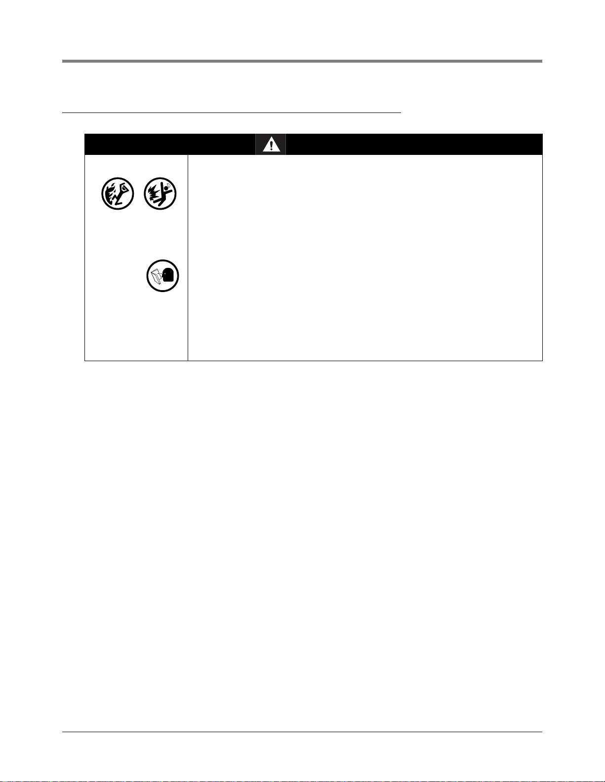
Safety Symbols
The following safety symbols are used in this manual to alert you to important safety hazards and precautions.
EXPLOSIVE
Fuels and their vapors are extremely
explosive if ignited.
ELECTRICITY
High voltage exists in, and is supplied
to, the device. A potential shock hazard exists.
FLAMMABLE
Fuels and their vapors are extremely
flammable.
READ ALL RELAT ED MANUALS
Knowledge of all related procedures
before you begin work is important.
Read and understand all manuals
thoroughly. If you do not understand
a procedure, ask someone who does.
2
Page 9
EMR3 Setup and Operation Manual Safety Warnings
Safety Warnings
WARNING
This system operates near highly combustible fuel storage tanks.
Fire or explosion resulting in serious injury or death could result if the
equipment is improperly installed or modified or is used in any way other than
its intended use. Serious contamination of the environment may also occur.
T o e nsu re proper installation, o perati on, and continued saf e use of th is product:
1. Read and follow all instructions in this manual, including all safety
warnings.
2. Have equipment installed by a contractor trained in its proper installation
and in compliance with all applicable codes including: the National
Electrical Code; feder al, s tate, and local codes; and oth er appli cable saf ety
codes.
3. Ensure that this equipment is properly programmed.
4. Operate this equipment in accordance with the instructions in this manual.
5. Promptly investigate any alarm conditions.
6. Do not modify or use service parts other than those provided by VeederRoot. Substitution of components may impair intrinsic safety.
3
Page 10
EMR3 Setup and Operation Manual Display Head
D
e
Mode Labels
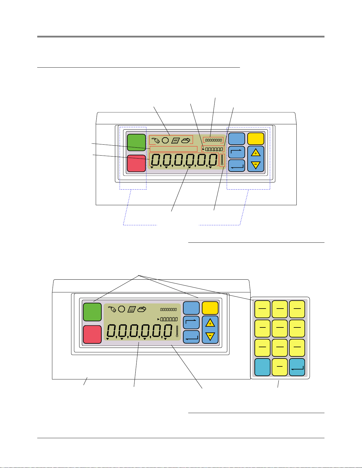
Display Head
The EMR3 Display Head display features are shown in Figure 1 and Figure 2.
escriptor Field
Register Field
emr/3.1/eps
Operating Icons
START
FINISH
Preset Indicator
VEEDER ROOT CO
VOLUME CURRENCY RATE SETUP
Mode Indicator
Standard Keypad
Temperature Icon
Grand Totalizer Field
Preset Field
MODE PRESET
NEXT
ENTER
Figure 1. Display Head Features
Tactile Feel Buttons
ABC2DEF
START
VEEDER ROOT CO
FINISH
VOLUME CURRENCY RATE SETUP
mr/3.2/eps
Cast Housing
Membrane Front Panel
MODE PRESET
NEXT
ENTER
QZ
1
JKL
GHI
5
4
TUV
PRS
8
7
(EXT)
0
Optional Keypad
3
MNO
6
WXY
9
ENTERCLEAR
Figure 2. Display Head with Optional Keypad
4
Page 11
EMR3 Setup and Operation Manual Boot-Up Test Sequence
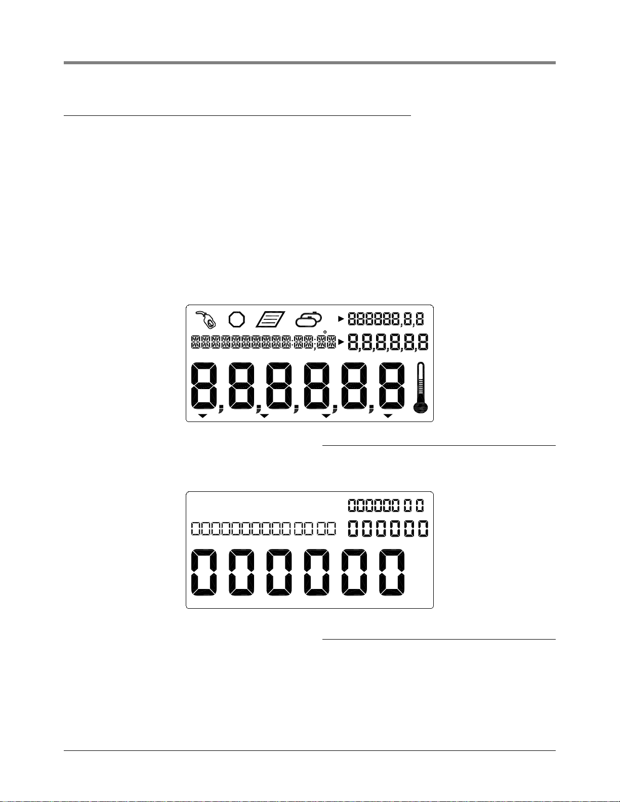
Boot-Up Test Sequence
When power is initiated to the Display Head, the screen will power up with a test sequence that satisfies the
requirements of the local Weights and Measures authority. The Display Head test sequence follows below:
• ROM TEST
• DATA BUS TEST (message not displayed)
• ADDRESS BUS TEST (message not displayed)
• RAM TEST
• CS TEST (message not displayed)
• NVRAM TEST
• INIT NVRAM
• All segments of the display are activated (see Figure 3):
Figure 3. All Segments Activated
• All zeros appear in the four display value fields (see Figure 4):
Figure 4. All Zeros Activated in the Display F ields
• On initial startup of EMR
(Figure 28 on page 26) and assign an unique Head Address for each Display Head. Because the factory default
Head Address is set to a “1”, one of the two Display Head’s addresses must be changed to a “2”. Caution!
Failure to do so will cause communication problems which will result in erratic operation.
3
Systems with two Display Heads, you must go to the Head Address Setup
5
Page 12

EMR3 Setup and Operation Manual Activating the Display
• Subsequently, if no button press or operation occurs in 30 seconds, the display will go blank and wait for a
button to be pressed to reactivate. Initially, when reactivated, the Display Head enters the Volume mode.
Once the unit has been setup, the default reactivation mode will be the Pre-Dispense mode you choose in
setup. Also, if you enable the OEM message in setup, it will scroll across the Descriptor field until the 30
second timeout.
Activating the Display
OEM MESSAGE DISABLED
Display is blank after the 30 second timeout. Press a button on the display, if the timeout follows setup, the predispense default mode is displayed. Otherwise the display on the screen prior to the timeout will display.
OEM MESSAGE ENABLED
Display is blank after 30 second timeout. Press a button on the display, the OEM message scrolls in the
Descriptor field. Press a button on the display, if the timeout follows setup, the pre-dispense default mode is
displayed. Otherwise the display on the screen prior to the timeout will display.
Display Value Fields
REGISTER FIELD
Six digits display the current volume, currency value, final price, or rate of fuel dispensed. The area is used to
display different selections. Values may display in various resolutions by selecting options in the C&C Mode.
Decimal and comma selection is available in this mode for 5 of the 6 digits.
PRESET FIELD
Six digits display the volume preset, volume preset count down, price, currency preset values, or currency preset
count down. The area is used to enter different selections of price, volume preset, or currency preset. Values may
display in various resolutions by selecting options in the C&C Mode. Decimal and comma selection is available in
this mode for 5 of the 6 digits.
TOTALIZER FIELD
Eight digits display the grand totalizer volume dispensed for the life of the product. Decimal selection is available in
this mode for 2 of the 8 digits.
DESCRIPTOR FIELD
Fourteen Characters at one time, with a rolling text capability for extended messages (up to 24 characters total),
displays description of values, labels, time/date, and instructional messages. labels, descriptions, and messages
are changeable in C&C Mode. Error codes will appear also in this field.
Display icons and indicators
• Emergency Stop - Octagon icon displayed when optional emergency stop switch contacts are closed. This
remote switch will be mounted near the Display Head and is pushed to stop flow and pulled to resume flow.
• Fueling - Fuel nozzle icon displayed constantly when system is ready to dispense. The Icon will flash when
approaching the time-out in delivery mode (30 seconds). See single delivery mode for further explanation.
• Te mp erat ure - The thermometer icon will display only when a temperature compensated product is selected.
6
Page 13

EMR3 Setup and Operation Manual Display Button Functions - Standard Keypad
• Printer - A page icon will display only when a printer is configured for the system. A slow flashing page icon is
displayed when the printer is actively printing. A fast flashing page icon is displayed when the printer requires
operator attention.
• Multiple Delivery - The multi-tank icon will display when the multiple delivery state is initiated.
• Mode Indicators - An indicator icon will point to the current Mode (Volume, Currency, Rate, or Setup) when
appropriate.
• Preset Indicator - An indicator icon will point to the Preset Field to indicate the Status of the Preset when in
that mode, otherwise it will not appear. It will flash when the Preset is set but disabled and will remain solid
when the Preset is enabled.
Display Button Functions - Standard Keypad
• START - Press to begin a fuel dispense transaction. When START is depressed for more than (2) seconds
multiple delivery mode is initiated.
• FINISH - Press to end a fuel dispense transaction. After transaction is complete, pressing FINISH will clear the
display of the last transaction and return you to the Pre-Dispense state. Press FINISH to toggle between
displaying the last transaction and the Pre-Dispense state. If depressed for more than a second after transaction
completed and last dispense is called, pressing FINISH initiates a Duplicate Ticket.
When multiple products are available and you are in the Select Product step prior to dispensing, pressing
FINISH will exit the dispense state, and return you to the pre-dispense state.
• MODE - Prior to pressing START Button, press MODE to cycle between Volume, Currency, and Setup Modes.
After pressing START Button, press MODE to cycle between Volume, Currency, and Rate Modes.
• PRESET - In Volume Mode, press to initiate presetting the amount of volume to dispense. Used in conjunction
with the NEXT, ‘+’, ‘-’, and ENTER Buttons to set a preset value.
In Currency Mode, press to toggle between price screen and currency preset screen. Used in conjunction with
the NEXT, ‘+’, ‘-’, and ENTER Buttons to select and set a Price or a preset value.
• NEXT - Press to enter the value fields - task or function. It is used also to move to the next lesser digit or next
letter in an entry to a value field. At the least significant digit it will wrap to the most significant digit.
• ENTER - Press to accept a selection, price code or data entry.
• Plus button which you press to scroll upward through the menu selections, to increment through numeric
characters 0 to 9, alpha characters Z to A, and special characters for each position in a selected display. Note:
throughout this manual, ‘+’ button will also refer to this button.
• Minus button which you press to scroll downward through the menu selections, to move from alpha
characters A to Z, numeric characters 9 to 0, and special characters for each position in a selected display.
Note: throughout this manual, ‘-’ button will also refer to this button.
Display Button Functions - Optional Keypad
• 0 through 9 - Press to enter alpha, numeric, or special character value into an active field. In alpha or numeric
selections, the cursor advances automatically upon selection of the next number or a different character
represented by the same button (negates the requirement for the NEXT button to be depressed for that
purpose).
• CLEAR - Press to enter a 0 in the active position of the Preset or Register fields. Press to enter blank spaces in
the active position of the descriptor field. Holding the button depressed for 2 seconds clears the entire
descriptor field being edited.
• ENTER - Press to accept a selection, price code, or data entry (functions the same as the ENTER button on the
standard keypad).
7
Page 14
Data Entry
t
P
t
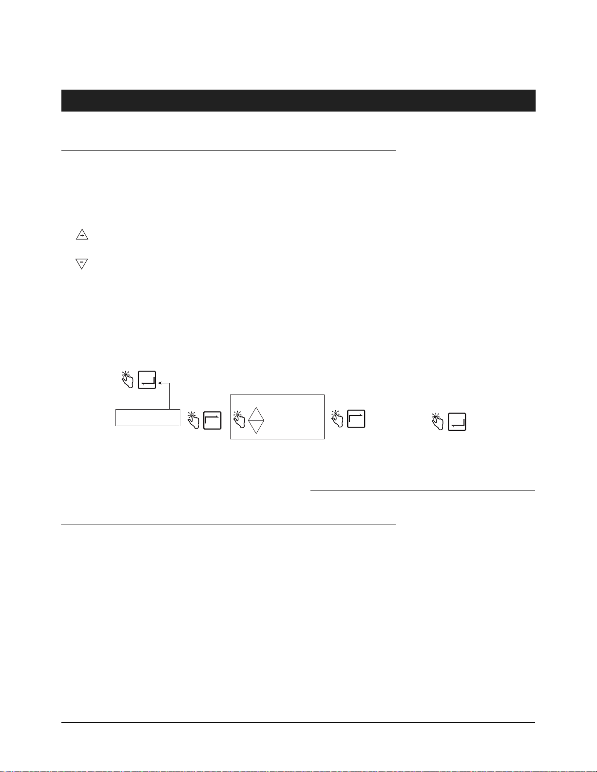
Navigation Buttons
The navigation buttons consist of the MODE, NEXT, ENTER, PRESET, and +/- buttons. They can be used to
either select and set parameters, or select and set alpha and numeric values.
• MODE - Press to navigate through the Modes; Setup, Volume, Currency, and Rate.
• NEXT - Press to move to the next submenu for a selection of a parameter or an alpha (Descriptor Field) or
(Preset Field) numeric selection.
• Press to scroll upward through the menu selections, to cycle through numeric characters 0 to 9, alpha
characters Z to A, and special characters for each position in a selected display.
• Press to scroll downward through the menu selections, to cycle through alpha characters A to Z, numeric
characters 9 to 0, and special characters for each position in a selected display.
• ENTER - Press to accept selection of parameter or alphanumeric values, or to return to prior menu selection.
• PRESET - Press to move to the preset countdown or preset entry.
Figure 5 illustrates the use of front panel buttons to make selections and navigate in Setup Mode.
ress ENTER to return
o LABEL CHANGES
ENTER
CURRENCY LABELS
NEXT
PRICE DOLLARS
DOLLAR PRICE
+
PRESET DOLLARS
DOLLAR REMAIN
-
DOLLAR PRESET
Note: 24 characters maximum.
Make your changes
to a label, pressing
up/down arrows to
scroll through the
NEXT
alphabet, and NEXT
to move from one
character of the label
to the next.
Figure 5. Using Front Panel Buttons to Navigate in Setup
Press ENTER to accep
changes and select
another label. Repeat
ENTER
until you enter all
label changes.
Data Entry with Standard Keypad
Upon entering the Descriptor or Preset Field with the use of the navigation buttons, a blinking cursor appears in
the far left of the field if, the field is empty or has a zero value. If the field contains data, a blinking cursor appears
one position to the left of the first non-blank field.
Pressing the +/ - buttons will scroll through alpha or numeric options for entry in the position. Holding down the +/
- buttons will scroll automatically without having to depress the button for each value. Pressing the NEXT button
will move the curser to the right for the next position. During alpha entries numeric, special characters, and blanks
are available. Pressing the NEXT button without scrolling to another selection will leave the current value and move
to the next location.
Subsequent presses of the NEXT button will shift the selected entry point to the right so the next digit/alpha/
space can be selected. When the last or least significant position is reached the subsequent press of the NEXT
button will wrap around to the most significant position. When changes are complete, press ENTER to accept
values.
8
Page 15

EMR3 Setup and Operation Manual Data Entry with Optional Keypad
Data Entry with Optional Keypad
Upon entering the Descriptor or Preset Field with the use of the navigation buttons the optional keypad will permit
alpha and numeric entries.
To enter a numeric in the Preset Field just select the appropriate button on the optional keypad. When a selection
is made, the curser will automatically sequence to the position to the right.
To enter an alpha, numeric, or special character in the Descriptor field, select the number button on the optional
keypad containing that alpha or numeric. Sequential depressions of the button will step through the alpha and
numeric values for that button. To move the curser to the next position, the NEXT button can be depressed.
Alternatively, when another, non-like button is depressed the curser will move to the right and the selection of the
value is obtained as aforementioned. In the case where the same alpha or numeric is desired the NEXT button will
sequence the curser to the next entry position.
When the desired entry is complete, press ENTER to accept.
The display head allows entries using both keypads in conjunction with each other or independently.
9
Page 16

EMR3 Operating States and Modes
System Operating States
The system has three operating states, Pre-Dispense, Dispense, and Finish.
PRE-DISPENSE STATE
Prior to pressing the START button, the system is in the Pre-Dispense state. The setting of system parameters,
pricing, and tax codes for a delivery are made in this state.
DISPENSE STATE
After pressing the START button (and selecting a product if setup for multiple products), the system enters the
Dispense state.
FINISH STATE
After pressing the FINISH button, the system is in the Finish State. The ticket is printed and the last delivery is
displayed.
System Operating Modes
Four operating modes are used in the EMR3 System. They are Volume, Currency, Rate, and Setup. These modes
can be navigated by use of the MODE button. In Setup, the default Mode for Pre-Dispense and Dispense states
can be set. The defaults may be changed through the User Setup menus
VOLUME MODE
The display will default to the Volume mode when the display head is first initialized. In the Pre-Dispense or
Dispense state the display will initiate with volume displayed in the numeric fields. Prior to the START button being
pressed, the mode will remain in Volume unless the MODE button is depressed to change the mode. It may be
changed to Currency, Setup, and back to Volume. If the mode is changed to Currency or Setup prior to delivery,
the mode will change to the default dispense state selected when the START button is depressed to begin that
delivery. At any time, the operator may select the Currency Mode or Rate Mode by depressing the MODE Button.
When in the Volume Mode the indicator will point to the volume label on the front panel.
CURRENCY MODE
The display may be configured in the Setup Mode to default to the currency display. In the Pre-Dispense or
Dispense state the display will initiate with currency displayed in the numeric fields. Prior to the START button
being pressed, the mode will remain in Currency unless the MODE button is depressed to change the mode. It
may be changed to Volume, Setup, and back to Currency. If the mode is changed to Volume or Setup prior to
delivery, the mode will change back to the default Dispense state selected when the START button is depressed to
begin that delivery. At any time, the operator may select the Volume Mode or Rate Mode by depressing the MODE
Button. When in the Currency Mode the indicator will point to the currency label on the front panel.
RATE MODE
The display may show flow rate by depressing the MODE button when the operator is able to deliver product. The
operator cannot access Rate Mode unless the START button initiating a delivery is pressed. The Rate Mode can
be selected as the default dispense state in the Setup Mode. During a delivery, the operator may display the flow
rate by using the MODE button to select Rate. When in the Rate Mode the indicator will point to the rate label on
the front panel.
10
Page 17

EMR3 Setup and Operation Manual System Operating Modes
SETUP MODE
The user can access the Setup Mode before a delivery to change a variety of parameters that are not required to
be under weights & measure seal. Once the delivery state is active, the Setup Mode cannot be accessed. The
Setup Mode is used to enter price codes, default mode setting, single flow and fast flow knock-off values and
other non-metrological settings. The operator can exit the mode by depressing the MODE button at any time.
When in the Setup Mode the indicator will point to the setup label on the front panel. Detailed information on how
to set the parameters is explained the setup sections of this manual.
CALIBRATION AND CONFIGURATION (C&C) MODE
The C&C Mode is entered by a trained technician following instructions in the EMR3 Installation Guide (V-R P/N
577013-758). When the display head is powered up after the C&C Mode is enabled, the C&C related parameters
of the Setup Mode are displayed. C&C Mode is used to set up various calibration and configuration parameters,
which when made, are sealed for metrological conformity. All C&C Mode parameters can be viewed by the user in
the Setup Mode, but no changes are allowed. The operator can not exit the C&C Mode until the C&C switch is
returned to its normal operating state.
11
Page 18

Setup Mode
Initiating the Setup Mode
1. Turn On power to the Display Head and wait until the boot-up sequence completes.
2. Depress the MODE button until the indicator at the bottom of the display points to Setup.
3. On initial power-up of the Display Head, the first Setup Mode category, PRICING, displays in the Descriptor
Field. Press NEXT to enter Pricing Setup, or continue to press the button to step through the remaining
Setup Mode categories. Press NEXT to enter any category once it displays in the Descriptor Field.
Setup Mode Categories
The non-metrologically controlled Setup Mode categories for the EMR3 System are:
• Enter Security Code - enables user log in/out procedure. (Note: This prompt will not display on initial power-up
of the Display Head. If you have enabled Security Code in the C&C Mode, this prompt will be the first category
to display on entering Setup Mode).
• Pricing setup - sets up to 15 different price codes with tax/discount code assignments.
• Tax/ Di scou nt setup - sets up to 15 different tax/discount (T/D) codes with up to 6 different T/D modifiers per
code.
• Defaults setup - lets you set the mode you want the Display Head to enter when beginning pre-dispense and
dispense operations; and lets you enable/disable volume and currency mode presets.
• Relay Control setup - sets the shutoff points for flow control relays 1 and 2 for preset deliveries.
• Security setup - sets the user Passcodes and user access to certain Setup Mode categories. (This setup only
displays after enabling Security Code in the C&C Mode).
• Printer Option setup - sets optional printer type and distance from top of ticket to first printed line.
• View Records setup - lets you select to either view or print any of the last 50 transaction records.
• Restore Records - Allows the user to restore (download from IB to Display Head) up to the last 50
transactions.
• Shift setup - sets up shift start/end times, start/end odometer readings, and tank loadings. Also within Shift
setup, you can print out shift reports.
• Date Format setup - sets the format of year, month, and date for use in display and printouts.
• Time/ Date setup - lets you enter the current time and date.
• System Address setup - sets the addressing and configuration of the individual EMR
inputs from, and outputs to, the system.
3
components and their
• Time Delays setup - sets the delay (in seconds) after which the display will go blank if there is no activity.
• Version Number - lets you view system device version numbers.
• C&C - lets you step through and view, but not change, the C&C Mode setups (see page 29).
Instructions for setting up the Setup Mode categories are shown in the figures that follow. In some cases multiple
figures are used to explain sub-procedures within a Setup Mode category.
Note, once you have entered a Setup Mode category (pressing NEXT), do not press the ‘+’, ‘-’ buttons in that
setup if you do not intend to change a value, because when you press ENTER, the change, even if unintended, will
be accepted. If you want to view setup settings without making changes, press NEXT to move ‘into’ a category’s
setup and ENTER to ‘back out’ of the setup.
12
Page 19
EMR3 Setup and Operation Manual Setup Mode Categories
ENTER SECURITY CODE
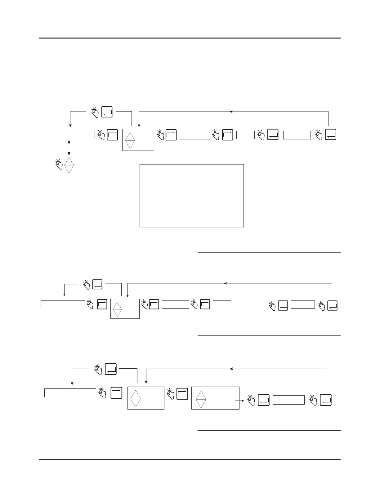
Figure 6 illustrates the initial logging in procedure using the default Passcode after Security Codes are enabled in
C&C Mode (see Figure 51). Figure 7 shows the procedure for logging in using an assigned Passcode, and
Figure 8 shows how to log out.
ENTER
ENTER SECURITY CODE
Press the up/down
buttons to cycle
+
through remaining
-
Setup Mode categories
PRICING
TAX/DISCOUNT
DEFAULTS
RELAY CONTROL
SECURITY
PRINTER OPTION
VIEW RECORDS
RESTORE RECORD
SHIFT
DATE FORMAT
TIME/DATE
SYSTEM ADDRESS
TIME DELAYS
VERSION NUMBER
C AND C
ENTER SECURITY CODE
NEXT NEXT NEXT
USER 1
+
USER 2
+
USER 3
-
LOGGED OUT LOGGED IN000000
Security Code Notes:
1. Upon powering down, the Security Code status
for all users is returned to LOGGED OUT.
2. User 1, Supervisor, must log out or the capability
of changes will remain active if power is not
cycled.
3. Only one user can be logged in at a time. If
another user logs in, other users are automatically
logged out.
IMPORTANT! Security codes do not prevent
dispensing, they only control setup options.
ENTER
NEXT NEXT NEXT
USER 1
+
USER 2
+
USER 3
-
LOGGED OUT LOGGED INXXXXXX
ENTER ENTER
Default code
Figure 6. Logging In Using Default Passcode
ENTER your assigned
pass code.
Press the up/down
arrows to scroll
through the numbers,
and NEXT to move
from one digit of the
code to the next.
ENTER ENTER
ENTER SECURITY CODE
ENTER
NEXT
Figure 7. Logging In Using Assigned Passcode
USER 1
+
USER 2
+
-
USER 3
NEXT
LOGGED IN
+
LOGGED OUT
+
-
ENTER ENTER
LOGGED OUT
Figure 8. Logging Out
13
Page 20
EMR3 Setup and Operation Manual Setup Mode Categories
6 0, 1, 2, 3, 4, and/or 5
PRICING
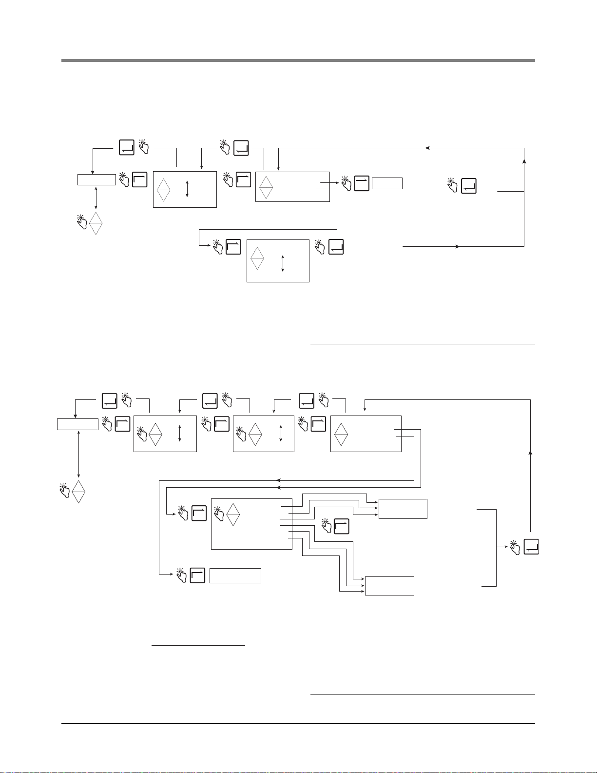
Figure 9 illustrates Pricing setup in Setup Mode.
ENTER
PRICING
+
-
TAX/DISCOUNT
DEFAULTS
RELAY CONTROL
SECURITY
PRINTER OPTION
VIEW RECORDS
RESTORE RECORD
SHIFT
DATE FORMAT
TIME/DATE
SYSTEM ADDRESS
TIME DELAYS
VERSION NUMBER
C AND C
ENTER SECURITY CODE
NEX
Press the up/down
buttons to cycle
through remaining
Setup Mode categories
T
PRICE CODE 1
+
+
-
PRICE CODE 15
ENTER
NEX
T
CHANGE PRICE X
+
ASSIGN TAX/DIS
+
-
Note: Select ASSIGN TAX/DIS if you
want to also assign a tax/discount to
Price Code X.
NEX
ASSIGN NO T/D
T
ASSIGN T/D 1
+
+
-
ASSIGN T/D 15
Note: ASSIGN NO T/D is the
default selection for all Price
Codes.
TAX/DISCOUNT
Figure 10 illustrates Tax/Discount setup in Setup Mode.
ENTER ENTER ENTER
TAX/DISCOUNT
Press the up/down
+
buttons to cycle
through remaining
-
Setup Mode categories
DEFAULTS
RELAY CONTROL
SECURITY
PRINTER OPTION
VIEW RECORDS
RESTORE RECORD
SHIFT
DATE FORMAT
TIME/DATE
SYSTEM ADDRESS
TIME DELAYS
VERSION NUMBER
C AND C
ENTER SECURITY CODE
PRICING
NEXT
T/D CODE 1
+
+
-
T/D CODE 15
IMPORTANT!
Only TAX PERCENT and DIS PERCENT T/D Values can access the
ASSIGN TO LINE feature. You must select at least one ASSIGN TO
LINE choice for TAX PERCENT and/or DIS PERCENT or they will not
be implemented. Depending on their initial T/D Line Value chosen
above, either one can also be assigned to other T/D Lines as follows:
(Note: Line 0 is the delivery's SUBTOTAL [volume times base price].)
Initial T/D Permissible additional
Line Value T/D Line Assignments
1 0
2 0, and/or 1
3 0,1, and/or 2
4 0,1,2, and/or 3
5 0,1,2,3, and/or 4
NEXT NEXT
Note: The order in which the T/D Value selections
are implemented begins with T/D Line 1 Value
and ends with T/D Line 6 Value.
NEXT
Note: UNUSED is the default T/D Value setting.
NEXT
+
-
ASSIGN TO LINE
T/D LINE 1
+
+
-
T/D LINE 6
TAX PERCENT
TAX PER VOLUME
SURCHARGE
DIS PERCENT
DIS PER VOLUME
DIS SURCHARGE
UNUSED
NEX
Press ENTER to assign
ENTER
a tax/discount selection
to Price X
CHNG T/D VALUE
+
CHNG T/D ASSGN
+
-
NEXT
Press up/down
PRICE X
T
Note: T AX PERCENT
is a percentage.
TAX PER VOLUME
and TAX SURCHARGE
are currency units.
Enter tax % as a percent
(e.g., 6 not 0.06)
ENTER NEW DIS
Note: DIS PERCENT
is a percentage.
DIS PER VOLUME
and DIS SURCHARGE
are currency units.
Enter Dis % as a percent
(e.g., 6 not 0.06)
to change digit
and NEXT to
move to next digit.
ENTER NEW TAX
ENTER
Figure 9. Pricing Se tup
Press up/down to
change digit and
NEXT to move to
next digit.
Press up/down to change
digit and NEXT to move to
next digit.
Press to accept
choice
ENTER
Figure 10. Tax/Discount Setup
14
Page 21
EMR3 Setup and Operation Manual Setup Mode Categories
s.
Press ENTER
D
during Dispensing.
DEFAULTS
Figure 11 illustrates Defaults setup in Setup Mode.
ENTER
DEFAULTS
Press the up/down
+
buttons to cycle
through remaining
-
Setup Mode categories
RELAY CONTROL
SECURITY
PRINTER OPTION
VIEW RECORDS
RESTORE RECORD
SHIFT
DATE FORMAT
TIME/DATE
SYSTEM ADDRESS
TIME DELAYS
VERSION NUMBER
C AND C
ENTER SECURITY CODE
PRICING
TAX/DISCOUNT
NEXT
START MODES
+
PRESETS
+
-
See Start Modes and
Presets figures that
follow for these setup
Figure 11. Defaults Setup
Start Modes
Figure 12 illustrates Start Modes setup in Setup Mode. Start Modes is used to set what screen (mode) will be
displayed before the delivery (pre-dispense) and during the delivery (Dispense). The default Start Mode is Volume.
to return to
EFAULTS
ENTER
ENTER
NEXT
NEXT
START MODES
PRE-DISPENSE
DISPENSE
NEXT
PRE-DISPENSE
+
DISPENSE
+
-
VOLUME MODE
NEXT
NEXT
+
CURRENCY MODE
+
-
SETUP MODE
VOLUME MODE
+
CURRENCY MODE
+
-
RATE MODE
Select the default mode
you want the Display
Head to automatically
enter after finishing a
Delivery.
Select the default mode
you want the Display
Head to automatically
enter once the optional
flow valves open and/or
ENTER
Press ENTER
to accept
selection and
return to
Figure 12. Start Modes Setup
15
Page 22

EMR3 Setup and Operation Manual Setup Mode Categories
Press ENTER
D
3 Currency amounts.
Presets
Figure 13 illustrates Presets setup in Setup Mode.
to return to
EFAULTS
ENTER
PRESETS
NEXT
VOLUME MODE
+
CURRENCY MODE
+
-
NEXT
RELAY CONTROL
Figure 14 illustrates Relay Control setup in Setup Mode.
ENTER
ENTERENTER
NEXT
PRESET 1
+
PRESET 2
+
-
PRESET 3
Note: If enabled, this feature lets
you enter up to 6 different delivery
presets - 3 Volume amounts and/or
PRESET ENABLE
+
PRESET DISABLE
+
-
Make your changes
to the preset, pressing
up/down arrows to
numbers, and NEXT
to move from one
digit of the preset
to the next.
Press ENTER
to accept
ENTER
selection and
return to
Figure 13. Presets Setup
RELAY CONTROL
Press the up/down
buttons to cycle
+
through remaining
-
Setup Mode categories
SECURITY
PRINTER OPTION
VIEW RECORDS
RESTORE RECORD
SHIFT
DATE FORMAT
TIME/DATE
SYSTEM ADDRESS
TIME DELAYS
VERSION NUMBER
C AND C
ENTER SECURITY CODE
PRICING
TAX/DISCOUNT
DEFAULTS
NEX
Note: Flow control relays are located
+
T
+
-
RELAY 1
RELAY 2
in the IB box. Each Display Head (1 or 2)
has two relays assigned to it. Applications
with only one solenoid valve only use the
single-flow relay designated as RELAY 2.
SET SLOW FLOW
NEX
T
Note: This entry sets the number of
volume units prior to the finish of a preset
delivery, at which point, Relay 1
(Fast Flow) will open and close the
fast flow solenoid. Recommended
setting is 5 volume units.
SET ADVANCE STOP
NEX
T
Note: This entry sets the number of
volume units prior to the finish of a preset
delivery, at which point, Relay 2
(Single Flow) will open and close the
single flow solenoid. Recommended
setting is 0.1 volume units.
Press up/down arrows
to select a number and
NEXT to move from
NEX
T
one digit of the number
to the next.
Press up/down arrows
to select a number and
NEXT to move from
NEX
T
one digit of the number
to the next.
ENTER
Press ENTER
to accept
selection and
return to
Figure 14. Relay Control Setup
16
Page 23

EMR3 Setup and Operation Manual Setup Mode Categories
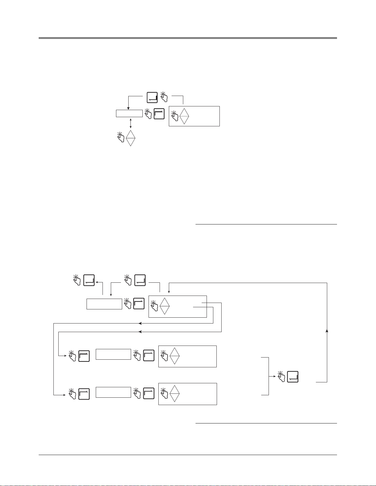
SECURITY
Figure 15 illustrates the procedure for setting user Passcodes and user access to certain setup parameters.
ENTER ENTER
SECURITY
Press the up/down
+
buttons to cycle
through remaining
-
Setup Mode categories
PRINTER OPTION
VIEW RECORDS
RESTORE RECORD
SHIFT
DATE FORMAT
TIME/DATE
SYSTEM ADDRESS
TIME DELAYS
VERSION NUMBER
C AND C
ENTER SECURITY CODE
PRICING
TAX/DISCOUNT
DEFAULTS
RELAY CONTROL
NEXT NEXT
USER 1
+
USER 2
+
USER 3
-
Note: Authorization to change pass codes and assignments is determined by
how you are logged in to the system (see Entering Security - Logging In). The
table below describes a logged in user's ability to make these changes.
If Y ou are
Logged In as:
User 1
User 2
User 3
+
CHANGE CODE
+
CHANGE ASSIGNMENTS
-
You Can Change
Pass codes for:
Users 1, 2, 3
User 2
User 3
NEXT
NEXT NEXT
You Can Change
Assignments for:
Users 2, 3
No one
No one
Enter a six-digit pass code.
XXXXXX
+
+
-
Press the up/down arrows
to scroll through the
numbers, and NEXT to
move from one digit of the
code to the next.
PRICING
TAX/DISCOUNT
DEFAULTS
RELAY CONTROL
PRINTER OPTION
VIEW RECORDS
RESTORE RECORDS
SHIFT
DATE FORMAT
TIME DATE
SYSTEM ADDRESS
TIME DELAYS
DELIVERY PRICE
ENTER
+
+
-
YES
NO
ENTER
Note: All assignments are set to Yes (default) which lets all logged in users access the listed setup
categories. When a selected setup category is set to No, access for the selected user is denied.
Figure 15. Passcode and Setup Access Setup
17
Page 24

EMR3 Setup and Operation Manual Setup Mode Categories
which is the default.
PRINTER OPTION
Figure 16 illustrates Printer Option setup in Setup Mode.
ENTER
PRINTER OPTION
Press the up/down
+
buttons to cycle
through remaining
-
Setup Mode categories
VIEW RECORDS
RESTORE RECORD
SHIFT
DATE FORMAT
TIME/DATE
SYSTEM ADDRESS
TIME DELAYS
VERSION NUMBER
C AND C
ENTER SECURITY CODE
PRICING
TAX/DISCOUNT
DEFAULTS
RELAY CONTROL
SECURITY
ENTER ENTER
+
NEXT NEXTNEXT
ENABLE PRINTER
+
DISABLE PRINTR
-
NEXT
Note: The minimum distance from
the top edge of the ticket down to
the first line of printing is 1 inch
and cannot be changed.
To increase the distance from the
top of the ticket to the first line you
change SET ADVANCE.
The minimum advance is 0 inches
SLIP PRINTER
+
ROLL PRINTER
+
-
1
Printer type assigned to this port must agree
with the printer type selected in Printer Option setup.
+
YES
+
NO
-
NEXT
1
1
SET ADVANCE
Each line advance is = to .167 inch. For example,
to have the first line print 2.5 inches from the top
you would need to add an additional 1.5 inches to
the fixed 1 inch space so you would enter 9 as the
advance (9 x .167 = 1.5 + 1 = 2.5"). Press up/down
arrows to select a number and NEXT to move from
one digit of the number to another.
+
ADVANCE
+
PRINT TEST PAGE
-
ENTER
Press ENTER
to accept
selection and
return to
Figure 16. Printer Option Setup
An example of Printer Format 1 (Delivery Ticket Format), selectable in the Printer Option setup above, is shown in
Figure 17. NOTE: The availability of certain printer labels is dependent on options selected.
18
Page 25

EMR3 Setup and Operation Manual Setup Mode Categories
P
***********************************
Header
(Up to 4 lines)
* Veeder-Root Co. *
* EMR-3 *
* *
* *
***********************************
Optional
Date/time
Delivery
Information
rice/Tax/Discount
Information
Totals
START MMM-DD-YYYY HH:MM:SS
FINISH MMM-DD-YYYY HH:MM:SS
TICKET NUMBER 50399
PROD DSCRPT X PROPANE
METER ID GENERIC 12345
TANK ID TANK DEFAULT
TOTALIZER START 4007.155
TOTALIZER END 4017.155
VOLUME GAL START 0.0000
GROSS VOLUME FINISH 10.000
NET VOLUME FINISH 10.000
AVG FLOW RATE (GPM) 11.111
TEMP THIS DELIVERY 61.00 F
VOLUME CORRECTED TO 60.0 F
COEFFICIENT OF EXPANSION 0.00160
PRICE/GALLON $ 2.0000
SUBTOTAL $ 20.000
%TAX T/D 1 % 10.0000
TAX/UNIT $ 0.2000
AMOUNT $ 2.0000
UNIT TAX T/D 2 $ 10.0000
AMOUNT $ 100.0000
SURCHARGE T/D 3 $ 10.0000
AMOUNT $ 10.0000
%DISCOUNT T/D 4 % 10.0000
DISCOUNT/UNIT $ -1.2200
AMOUNT SUB+T/D 1&2&3 $ -13.2000
UNIT DISCOUNT T/D 5 $ 10.0000
AMOUNT $ -100.0000
DISCOUNT T/D 6 $ 1.0000
AMOUNT $ -1.0000
FINAL PRICE/GALLON $ 0.9800
TOTAL NON-TAX LINES $ -94.00
TAX THIS DELIVERY $ 91.80
GRAND TOTAL $ 17.80
Trailer
You can count on us!
(Up to 3 lines)
19
Figure 17. Delivery Ticket Format
Page 26

EMR3 Setup and Operation Manual Setup Mode Categories
VIEW RECORDS
Figure 18 illustrates View Records setup in Setup Mode.
ENTER
VIEW RECORDS
Press the up/down
+
buttons to cycle
through remaining
-
Setup Mode categories
RESTORE RECORD
SHIFT
DATE FORMAT
TIME/DATE
SYSTEM ADDRESS
TIME DELAYS
VERSION NUMBER
C AND C
ENTER SECURITY CODE
PRICING
TAX/DISCOUNT
DEFAULTS
RELAY CONTROL
SECURITY
PRINTER OPTION
NEXT
Note: Up to the last 50 transaction records
are maintained in the Display Head for viewing
or printing. NO RECORDS displays if no records
are available.
RECORD 1
+
+
-
RECORD 50
NEXT
ENTER
NEXT
+
+
-
Prints out the
selected report
to the printer.
+
VIEW LINES
+
PRINT RECORD
-
Note: View each line or print
the selected report.
TICKET NUMBER
START (Date/Time)
FINISH (Date/Time)
PROD DSCRPT X
TOTALIZER START
TOTALIZER END
GROSS VOLUME FINISH
NET VOLUME FINISH
TEMP THIS DELIVERY
PRICE/GALLON
SUBTOTAL
T AX THIS DELIVERY
TOTAL NON-TAX LINES
GRAND TOTAL
ENTER
ENTER
Displays if
TC enabled
Displays if
pricing
enabled
20
Figure 18. View Records Setup
Page 27

EMR3 Setup and Operation Manual Setup Mode Categories
RESTORE RECORDS
Figure 19 illustrates Restore Records procedure in Setup Mode.
RESTORE RECORDS
Press the up/down
+
buttons to cycle
through remaining
-
Setup Mode categories
SHIFT
DATE FORMAT
TIME/DATE
SYSTEM ADDRESS
TIME DELAYS
VERSION NUMBER
C AND C
ENTER SECURITY CODE
PRICING
TAX/DISCOUNT
DEFAULTS
RELAY CONTROL
SECURITY
PRINTER OPTION
VIEW RECORDS
SHIFT
NEXT
+
+
-
DECLINE
ACCEPT
ENTER
ENTER
RESTORING TRANSCTION
50, 49, ... 1
Note: Last 50 Transactions are being
restored. Counts down from 50 to 1
(number of stored transactions may
be less than 50)
NO TRANSACTIONS IN IB
Note: No transactions in IB memory
Figure 19. Restore Records Procedure
ENTER
Figure 20 illustrates Shift setup and the Shift Report printing procedure in the Setup Mode.
Figure 21 illustrates the format of a shift report. When a shift report is selected, a separate report will be printed
for each product if transactions for that product were recorded in the selected shift.
21
Page 28

EMR3 Setup and Operation Manual Setup Mode Categories
Press ENTER to accept any changes and/or
ENTER
continue pressing to return to SHIFT
SHIFT
Press the up/down
++
buttons to cycle
through remaining
Setup Mode categories
DATE FORMAT
TIME/DATE
SYSTEM ADDRESS
TIME DELAYS
VERSION NUMBER
C AND C
ENTER SECURITY CODE
PRICING
TAX/DISCOUNT
DEFAULTS
RELAY CONTROL
SECURITY
PRINTER OPTION
VIEW RECORDS
RESTORE RECORD
NEXT NEXT
SHIFT TIME
++
ODOMETER
TANK LOAD
PRINT REPORT
NEXT
NEXT
NEXT
++
1
If any transactions are made between shifts, they will be recorded in a new shift
having a start time that is the same as the start of the first of those transactions and an end time
that is the same as the Start time you enter for the next shift.
Also, if a new shift is started by entering a Start Time, the previous shift, if not ended, will be assigned an
end time that is the same as the Start time you enter for the new shift.
++
++
++
Note: Print Report 1 will only
display if you in an active shift.
1
START TIME : HH:MM
END TIME : HH:MM
ODOMETER START
ODOMETER END
PROD DSCRPT 1
PROD DSCRPT 8
PRINT REPORT 1
PRINT REPORT 2
PRINT REPORT 3
PRINT REPORT 4
NEXT
NEXT
NEXT
++
ACCEPT : HH:MM
DECLINE : HH:MM
ENTER ODOMETER
++
ENTER LOAD
REMAINING VOL
NEXT
ENTER
NEXT
ENTER
ENTER
To enter the truck mileage on
the truck odometer at the
start or end of a shift press
the up/down arrows to scroll
through the numbers, and
NEXT to move from one
number to the next.
++
START TIME : HH:MM
END TIME : HH:MM
Prints out shift report 1 (current shift)
++
START TIME : HH:MM
END TIME : HH:MM
Prints out shift report 2 (previous shift)
ENTER
To enter the amount loaded
into the Tank for the selected
product, press the up/down
NEXT
arrows to scroll through the
numbers, and NEXT to move
from one number to the next.
View the volume remaining in
NEXT
the Tank for the selected product.
ENTER
ENTER
ENTER
Returns to Print Report 1 message.
Returns to Print Report 2 message.
++
NEXT
ENTER
NEXT
ENTER
START TIME : HH:MM
END TIME : HH:MM
Prints out shift report 3 (shift prior to 2)
++
START TIME : HH:MM
END TIME : HH:MM
Prints out shift report 4 (shift prior to 3)
Figure 20. Shift and Shift Report Setup
Returns to Print Report 3 message.
ENTER
ENTER
Returns to Print Report 4 message.
22
Page 29

EMR3 Setup and Operation Manual Setup Mode Categories
)
Report Line Item Source
SHIFT BEGIN:
SHIFT END:
ODOMETER START:
ODOMETER END:
MILES DRIVEN:
PROD DSCRPT X:
METER ID:
BEGINNING VOLUME:
LOADED VOLUME:
ENDING VOLUME:
TOTAL GROSS VOLUME:
SINGLE DELIVERIES:
MULTIPLE DELIVERIES:
TRANSFER DELIVERIES:
ITEMIZED DELIVERIES:
TOTAL VOLUME:
TOTAL VOLUME NO PRICE:
TOTAL VOLUME PRICED:
TOTAL SALES W/O TD:
TOTAL TAX/DISCOUNT 1:
TOTAL TAX/DISCOUNT 2:
TOTAL TAX/DISCOUNT 3:
TOTAL TAX/DISCOUNT 4:
TOTAL TAX/DISCOUNT 5:
TOTAL TAX/DISCOUNT 6:
GRAND TOTAL:
Starting time/date of the shift
Ending time/date of the shift (only displayed if shift has ended )
Odometer reading entered at the start of the shift
Odometer reading entered at the end of the shift
Miles driven during the shift (= odometer end - odometer start)
Name assigned to the product (e.g., gasoline)
Meter ID number assigned to the unit
Total volume at the beginning of the shift (= ending volume of last shift)
Compensated or uncompensated load entered in "Tanker Load" shift setup
Volume remaining at the end of the shift (= beginning volume + loaded volume - total volume)
Uncompensated volume
Number of single deliveries during a shift
Number of multiple deliveries during a shift
Number of transfer deliveries during a shift
Total number of itemized deliveries (= single deliveries + multiple deliveries)
Compensated (or uncompensated) volume (differs from total gross vol if the product is compensated)
Total volume that has no price code associated with it
Total volume that has a price code associated with it
Total contribution of sales from the base price (w/o any T/D associated with it)
Total contribution of T/D 1 to the total sales
Total contribution of T/D 2 to the total sales
Total contribution of T/D 3 to the total sales
Total contribution of T/D 4 to the total sales
Total contribution of T/D 5 to the total sales
Total contribution of T/D 6 to the total sales
Total sales during a shift (= total sales w/o T/D + Total T/D 1 + Total T/D 2 + Total T/D 3 + Total T/D 4 + Total T/D 5 + Total T/D 6
DATE FORMAT
Figure 22 illustrates Date Format setup in Setup Mode.
Figure 21. Shift Report Format
DATE FORMAT
Press the up/down
+
buttons to cycle
through remaining
-
Setup Mode categories
TIME/DATE
SYSTEM ADDRESS
TIME DELAYS
VERSION NUMBER
C AND C
ENTER SECURITY CODE
PRICING
TAX/DISCOUNT
DEFAULTS
RELAY CONTROL
SECURITY
PRINTER OPTION
VIEW RECORDS
RESTORE RECORD
SHIFT
ENTER
NEX
T
YEAR FORMAT
+
MONTH FORMAT
+
SEQUENCE
-
SEPARATE CHAR
NEX
NEX
NEX
NEX
T
+
4 DIGIT YEAR
+
2 DIGIT YEAR
-
T
+
3 CHAR MONTH
+
2 DIGIT MONTH
-
T
T
MONTH DAY YEAR
+
YEAR MONTH DAY
+
-
DAY MONTH YEAR
DASH
+
PERIOD
+
-
SLASH
ENTER
ENTER
ENTER
ENTER
Figure 22. Date Format Setup
23
Page 30

EMR3 Setup and Operation Manual Setup Mode Categories
Press up/down arrows to scroll through the
s.
or
TIME/DATE
Figure 23 illustrates Time/Date setup in Setup Mode.
MMM DD HH:MM:SS YYYY
Press the up/down
+
buttons to cycle
through remaining
-
Setup Mode categories
SYSTEM ADDRESS
TIME DELAYS
VERSION NUMBER
C AND C
ENTER SECURITY CODE
PRICING
TAX/DISCOUNT
DEFAULTS
RELAY CONTROL
SECURITY
PRINTER OPTION
VIEW RECORDS
RESTORE RECORD
SHIFT
DATE FORMAT
choices, and NEXT to move from one
group of the date, time, or year to
another. Press ENTER to accept change
Figure 23. Date/Time Setup
SYSTEM ADDRESS
Figure 24 illustrates System Address setup in Setup Mode. The setups shown in Figure 25 through Figure 29
must be followed to set the addresses of each component connected to each IB.
ENTER
SYSTEM ADDRESS
Press the up/down
+
buttons to cycle
through remaining
-
Setup Mode categories
TIME DELAYS
VERSION NUMBER
C AND C
ENTER SECURITY CODE
PRICING
TAX/DISCOUNT
DEFAULTS
RELAY CONTROL
SECURITY
PRINTER OPTION
VIEW RECORDS
RESTORE RECORD
SHIFT
DATE FORMAT
TIME/DATE
NEX
T
IB ADDRESS
+
PORT 1 ASSIGN
PORT 2 ASSIGN
+
-
HEAD ADDRESS
PRINTER ADDRESS
IMPORTANT! When the Head Address is set to
2, the selections for IB Address and the PORT
assignments are no longer valid. Only Head
Address 1 has the capability of setting port
assignment and IB address parameters.
NEX
T
See Address Setup
figures that follow f
each selection's
setup procedure
Figure 24. System Address Setup
24
Page 31

EMR3 Setup and Operation Manual Setup Mode Categories
t
P
t
t
P
t
IB Address Setup
Figure 25 illustrates the IB Address setup selections (the default IB address is 1). This setup is necessary only
when there are more than one IBs connected in a network.
ress ENTER to return
o SYSTEM ADDRESS
ENTER
SET IB ADDRESS 1
IB ADDRESS*
*IB NETWORK ADDRESS
Note: an IB's Port 1 and 2 network addresses are automatically
assigned by the EMR3 System and are shown in the table
below for reference only.
IB ADDRESS LOCAL PORT 1 LOCAL PORT 2
1 1 2
2 3 4
3 5 6
4 7 8
5 9 10
6 11 12
7 13 14
8 15 16
9 17 18
10 19 20
11 21 22
12 23 24
13 25 26
14 27 28
15 29 30
16 31 32
NEX
T
+
-
SET IB ADDRESS 16
Press ENTER to accep
ENTER
choice and return to
IB ADDRESS.
Figure 25. IB Address Setup
Port 1 Assign
Figure 26 illustrates Port 1 Assign setup choices.
ress ENTER to return
o SYSTEM ADDRESS
ENTER
PORT 1 ASSIGN
1
Printer type assigned to this port must agree with the printer type selected in Printer Option setup. Slip
printer is Epson model TM-295 (V-R Kit #846000-020). Slip printer is the standard printer, and is the
default PORT 1 assignment.
2
OBC selection configures the port for RS-232 serial communication between the EMR system and an
onboard computer. Consult Veeder-Root for required communication protocol.
3
PC SETUP selection allows communication between the PC Setup program and the EMR3.
4
AUX selection configures the port for communication between the EMR system and other peripheral
equipment to be approved by Veeder-Root.
NEXT
SLIP PRINTER
+
ROLL PRINTER
OBC
-
PC SETUP
AUX
1
2
3
4
ENTER
Press ENTER to accep
choice and return to
PORT 1 ASSIGN.
Figure 26. Port 1 Assign Setup
25
Page 32

EMR3 Setup and Operation Manual Setup Mode Categories
P
t
t
P
t
Port 2 Assign
Figure 27 illustrates Port 2 Assign setup choices.
ress ENTER to return
o SYSTEM ADDRESS
ENTER
PORT 2 ASSIGN
1
Printer type assigned to this port must agree with the printer type selected in Printer Option setup. Slip
printer is Epson model TM-295 (V-R Kit #846000-020). Slip printer is the standard printer.
2
OBC selection configures the port for RS-232 serial communication between the EMR system and an
onboard computer. Consult Veeder-Root for required communication protocol. This is the default
PORT 2 assignment.
3
PC SETUP selection allows communication between the PC Setup program and the EMR3.
4
AUX selection configures the port for communication between the EMR system and other peripheral
equipment to be approved by Veeder-Root.
NEXT
SLIP PRINTER
+
ROLL PRINTER
OBC
-
PC SETUP
AUX
1
2
3
4
Head Address
Figure 28 illustrates Head Address setup choices (note Caution in figure below).
ress ENTER to return
o SYSTEM ADDRESS
ENTER
Press ENTER to accept
ENTER
choice and return to
PORT 2 ASSIGN.
Figure 27. Port 2 Assign Setup
HEAD ADDRESS SET HEAD ADDRS 1*
IMPORTANT! When the Head Address is set to
2, the selections for IB Address and the PORT
assignments are no longer available. Only
Head Address 1 has the capability of setting
the port assignment parameters.
NEX
T
+
SET HEAD ADDRS 2
-
*The default setting is 1.
CAUTION! For a 2 Display Head
system the Head Addresses must
be unique (i.e., 1 and 2).
CAUTION! After setting a new head
address, cycle power to the IB box.
Failure to do so may result in either an
IB comm failure or a reset problem.
Press ENTER to accep
ENTER
choice and return to
HEAD ADDRESS.
Figure 28. Head Address Setup
Initial Remote Display Setup
Connect the cable from the Master Display Head to the DH#1 connector located in the IB box. Once powered,
enter the Setup Mode and set the Head Address to 1 (default) (Figure 28). Connect the cable coming from the
Remote Display to the DH#2 connector located in the IB box. Once powered, enter the Setup Mode and set the
Head Address to 2 (Figure 28). After setting a new head address, cycle power to the IB box. Failure to do so may
result in either an IB comm failure or a reset problem.
the NEXT button to select which Display Head will be the master, such as LOCAL EMR HEAD 1. Press ENTER
until CONFIGURE I/O is displayed.
Exit the C&C Mode and return both Display Heads to the Volume Mode. Cycle power Off and On to the IB and
verify Remote Display operation by simulating a delivery
Put the Remote Display into the C&C Mode and enable it as a Remote Display (see Figure 45 on page 42). Press
26
Page 33

EMR3 Setup and Operation Manual Setup Mode Categories
t
P
t
Printer Address
Figure 29 illustrates Printer Address setup choices.
ress ENTER to return
o SYSTEM ADDRESS
This menu selects the printer for this Display Head. To select printer on Host IB (the IB to which this Display Head is wired),
use Local Printer 1 for printer on Port 1 (if assigned) or use Local Printer 2 for printer on Port 2 (if assigned). Use port address
from table below to print to a printer connected to an IB other than the one to which this Display Head is wired.
IB ADDRESS PORT 1 PORT 2
1 1 2
2 3 4
3 5 6
4 7 8
5 9 10
6 11 12
7 13 14
8 15 16
9 17 18
10 19 20
11 21 22
12 23 24
13 25 26
14 27 28
15 29 30
16 31 32
ENTER
PRINTER ADDRESS LOCAL PRINTER 1
NEX
T
+
LOCAL PRINTER 2
-
SET PRINTER 1
SET PRINTER 32
For example, if this Display Head is wired
to IB 3 and you would like to print to a
printer wired to Port 2 of IB 5, select
Set Printer 10 from the menu above.
Press ENTER to accep
ENTER
choice and return to
PRINTER ADDRESS.
27
Figure 29. Printer Address Setup
Page 34

EMR3 Setup and Operation Manual Setup Mode Categories
TIME DELAYS
Figure 30 illustrates Time Delay setup in Setup Mode.
ENTER
Press the up/down arrows
to scroll through the
TIME DELAYS SET SECONDS
Press the up/down
+
buttons to cycle
through remaining
-
Setup Mode categories
VERSION NUMBER
C AND C
ENTER SECURITY CODE
PRICING
TAX/DISCOUNT
DEFAULTS
RELAY CONTROL
SECURITY
PRINTER OPTION
VIEW RECORDS
RESTORE RECORD
SHIFT
DATE FORMAT
TIME/DATE
SYSTEM ADDRESS
NEX
+
T
BACKLIGHT
BLANK SCREEN
+
-
VOLUME
NEX
T
Note: Default is 30 seconds.
You can enter any delay from 10
up to 999 seconds after which
the display backlight will go off if no
buttons are pressed.
NEX
T
SET SECONDS
Note: Default is 30 seconds.
You can enter any delay from 10
up to 999 seconds after which
the display will go blank if no
buttons are pressed.
NEX
T
SET SECONDS
Note: Default is 30 seconds.
You can enter any delay from 10
up to 999 seconds after which
the display will return to the
Volume Mode display if no
buttons are pressed.
numbers, and NEXT
to move from one
number to the next.
Press the up/down arrows
to scroll through the
numbers, and NEXT
to move from one
number to the next.
Press the up/down arrows
to scroll through the
numbers, and NEXT
to move from one
number to the next.
ENTER
ENTER
ENTER
VERSION NUMBER
Figure 31 illustrates Version Number viewer in Setup Mode.
ENTER
VERSION NUMBER
Press the up/down
+
buttons to cycle
through remaining
-
Setup Mode categories
C AND C
ENTER SECURITY CODE
PRICING
TAX/DISCOUNT
DEFAULTS
RELAY CONTROL
SECURITY
PRINTER OPTION
VIEW RECORDS
RESTORE RECORD
SHIFT
DATE FORMAT
TIME/DATE
SYSTEM ADDRESS
TIME DELAYS
NEX
T
HEAD NUMBER
+
HEAD BOOT NUMBER
+
-
IB NUMBER
IB BOOT NUMBER
NEX
T
349785-00X
Displays the software version
of the Display Head
NEX
T
E0
NEX
T
349784-00X
Displays the software version
of the Interconnect Box
NEX
T
I0
ENTER
ENTER
Figure 30. Time Delay Setup
ENTER
ENTER
28
Figure 31. Version Number Viewer
Page 35

C&C Mode
y
rn
C
Initiating the C&C Mode
NOTE: You must first configure the display head for access to C&C Mode as instructed in the EMR3 Installation
Guide (V-R P/N 577013-758).
1. Press MODE button until the indicator at the bottom of the display points to SETUP.
2. The first C&C Mode category, LANGUAGE, displays in the Descriptor Field. Press NEXT to enter Language
Setup, or continue to press the button to step through the remaining C&C Mode Setup categories. Press
NEXT to enter any category once it displays in the Descriptor Field.
C&C Mode Setup Categories
• Language setup - sets the volume, currency, setup, and printer label descriptions.
• Display Syntax setup - sets the punctuation and decimal places for data displayed in the Preset, Register, and
Totaliz er Fie l ds.
• Te mp erat ure setup - sets optional temperature probe’s units to Fahrenheit or Celsius.
• Fuel Source setup - sets the meter ID, meter input signal type, and product descriptions.
• Meter Calibration setup - sets the calibration of the meter by product using one of three methods.
• Configure I/O setup - enables various inputs/outputs such as Emergency Stop and Remote Start & Stop
output.
• OEM Message setup - lets you enter the start up OEM message.
• Delivery Options setup - lets you enable/disable price changing within the delivery state as allowed by local
regulatory authority, select temperature compensation method, enable delivery timeout, and enable tank ID.
• Report Formats setup - lets you print or compose formats for the Delivery Ticket and Shift Report.
• Restart setup - allows you to reboot while maintaining current setups, or to reboot and reset all setup selections
to factory default settings as well as removing all current transaction records.
• Security Code setup - allows you to enable security code protection to limit access to selected Setup Mode
categories.
Instructions for setting up the C&C Mode setups are shown in the figures that follow. In some cases multiple
figures are used to explain sub-procedures within a C&C Mode category. Once you have entered a C&C Mode
category (pressing NEXT), do not press the or buttons in that setup if you do not intend to change a value,
because when you press ENTER, the change, even if unintended, will be accepted. If you want to view setup
settings without making changes, press NEXT to move ‘into’ a category’s setup and ENTER to ‘back out’ of the
setup.
IMPORTANT! If in a C&C Setup you press ENTER too many times, you may ‘back’ out of the C&C Mode and end
up somewhere in the Setup Mode menu. To reenter C&C Mode, follow the button presses in the diagram below:
ENTER SECURITY CODE*
PRICING
TAX/DISCOUNT
DEFAULTS
RELAY CONTROL
SECURITY*
Setup
Mode
ategories
PRINTER OPTION
VIEW RECORDS
RESTORE RECORDS
SHIFT
DATE FORMAT
TIME/DATE
SYSTEM ADDRESS
TIME DELAYS
VERSION NUMBER
C&C
+
C&C LANGUAGE
Press this key
until you see C&C
* (
Displays if Security is enabled)
NEXT
29
Press this ke
until you retu
to the desired
-
C&C Setup
category
Page 36

EMR3 Setup and Operation Manual C&C Mode Setup Categories
of the label to the next.
LANGUAGE
Figure 32 illustrates Language setup in C&C Mode.
Press ENTER to accept any changes
and/or continue pressing to return to LANGUAGE
ENTER
LANGUAGE
Press the up/down buttons
+
to cycle through remaining
C/C Mode categories
-
DISPLAY SYNTAX
TEMPERATURE
FUEL SOURCE
METER CALIBRTN
CONFIGURE I/O
OEM MESSAGE
DELIVERY OPTIONS
REPORT FORMATS
RESTART
SECURITY CODE
NEX
T
+
+
-
ENGLISH
FRENCH
NEX
LABEL CHANGES
NEX
T
+
NEX
T
NEX
T
T
Note:
1.
The default label for TANK ID is
TANK 1. For each transaction
the TANK ID is stored and may
be printed.
-
Note: 24 characters maximum.
+
-
Note: 24 characters maximum.
+
TANK ID
TANK 1
-
NEX
GALLONS
PRESET GALLONS
GALLON PRESET
GALLONS/MINUTE
PRICE DOLLARS
DOLLAR PRICE
ENTER PRICE
CLEAR PRICE
CHANGE PRICE
PRICE CODE
PRESET DOLLARS
DOLLAR REMAIN
DOLLAR PRESET
NO PRICE ENTRY
PRICE
T
PRINTER LABELS
+
VOLUME LABELS
+
CURRENCY LABELS
-
SETUP LABELS
Make your changes
to a label, pressing
up/down arrows to
scroll through the
NEX
T
alphabet, and NEXT
to move from one
character of the label
to the next.
Make your changes
to a label, pressing
up/down arrows to
scroll through the
NEX
T
alphabet, and NEXT
to move from one
character of the label
to the next.
Enter your Tank ID
label, pressing up/down
arrows to scroll through the
alphabet, and NEXT to
NEX
T
move from one character
of the label to the next.
Enter your Tank ID label,
pressing up/down arrows
NEX
T
to scroll through the
alphabet, and NEXT to
move from one character
Go to Printer Labels Setup (Next page)
Press ENTER to accept
changes and select
ENTER
another label. Repeat
until you enter all
label changes.
Press ENTER to accept
changes and select
another label. Repeat
ENTER
until you enter all
label changes.
Press ENTER to
ENTER
accept changes.
Press ENTER to
ENTER
accept changes.
30
Figure 32. Language Setup
Page 37

EMR3 Setup and Operation Manual C&C Mode Setup Categories
Printer Labels
Figure 33 illustrates Printer Label defaults used in Delivery Tickets and Shift Reports. You use this setup to edit the
text of any printer label, e.g., to change the label START to BEGIN (ref. Figure 48 to select the printout’s format).
Press ENTER to return
to LABEL CHANGES
Complete List of
Printer Labels (Defaults)
Designations in
Group
Code
A1
B1
C1
D1
E1
F1
A2
D2
A3
B2
C2
D3
E2
F2
software of
Adjacent Labels
TAX_PERCENT1
TAX_PER_VOLUME1
TAX_SURCHARGE1
DISCOUNT_PERCENT1
DISCOUNT_PER_VOLUME1
DISCOUNT_SURCHARGE1
TAX_PERCENT2
DISCOUNT_PERCENT2
TAX_PERCENT3
TAX_PER_VOLUME3
TAX_SURCHARGE3
DISCOUNT_PERCENT3
DISCOUNT_PER_VOLUME3
DISCOUNT_SURCHARGE3
ENTER
PRINTER LABELS
START
FINISH
VOLUME GAL START
NET VOLUME FINISH
GROSS VOLUME FINISH
TEMP THIS DELIVERY
VOLUME CORRECTED TO
COEFFICIENT OF EXPANSION
DENSITY
TICKET NUMBER
CALIBRATION
SUMMARY TICKET
OF
METER ID
MULTIPLE DELIVERY TICKET
PROD DSCRPT X
TANK ID
TOTALIZER START
TOTALIZER END
AVG FLOW RATE GPM
PRICE/GALLON
FINAL PRICE/GALLON
SUBTOTAL
PRICE INCLUDING TAX
PRICE EXCLUDING TAX
GRAND TOTAL
TAX THIS DELIVERY
TOTAL NON-TAX LINES
TAX T/D
UNIT TAX T/D
SURCHARGE T/D
DISCOUNT T/D
UNIT DISCOUNT T/D
DISCOUNT T/D
TAX/UNIT
DISCOUNT/UNIT
AMOUNT
AMOUNT
AMOUNT
AMOUNT
AMOUNT
AMOUNT
SUB
T/D
SHIFT BEGIN
SHIFT END
ODOMETER START
ODOMETER END
MILES DRIVEN
BEGINNING VOLUME
LOADED VOLUME
ENDING VOLUME
TOTAL GROSS VOLUME
SINGLE DELIVERIES
MULTIPLE DELIVERIES
ITEMIZED DELIVERIES
TRANSFER DELIVERIES
TOTAL TC VOLUME
TOTAL VOLUME
TOTAL TC VOL NO PRICE
TOTAL VOLUME NO PRICE
TOTAL TC VOL PRICED
TOTAL VOLUME PRICED
TOTAL SALES W/O TD
TOTAL TAX/DISCOUNT 1
TOTAL TAX/DISCOUNT 2
TOTAL TAX/DISCOUNT 3
TOTAL TAX/DISCOUNT 4
TOTAL TAX/DISCOUNT 5
TOTAL TAX/DISCOUNT 6
Veeder-Root Co.
EMR-3
"blank"
"blank"
You can count on us
"blank "
"blank"
"blank "
$
MULTIPLE DELIVERIES
AT ONE SITE
DUPLICATE TICKET
TRANSFER TICKET
NEXT
Scroll through and edit,
if desired, the actual
+
printed labels shown
-
in the dotted box below
Tax and Discount labels automatically print in 2 or 3 line
groups. The (A1, B1, etc.) to the left of the software designations indicate the label's group and line position (e.g. A1
prints first, A2 on next line, etc). The groups and printing
positions are:
A1 B1 C1 D1 E1 F1
A2 B2 C2 D2 E2 F2
A3 D3
(Only the A and D groups have 3 lines)
For example, if in any of your price codes, you assigned a
percentage tax to the base price, the A group would
indicate this adjustment and would print as:
%Tax T/D % XX.XXXX (A1)
Tax/Unit $ X.XXXX (A2)
Amount $ XX.XXXX (A3)
Note: Shift Report only.
Note: Any or all of these four lines
can be used for the header at the
top of the printed ticket.
Note: Any or all of these four lines
can be used for the trailer at the
bottom of the printed ticket.
Note: Delivery Ticket only.
NEXT
Make your changes
to a label, pressing
up/down arrows to
scroll through the
alphabet, and NEXT
to move from one
character of the label
to the next.
Press ENTER to accept
changes and select
ENTER
another label. Repeat
until you enter all
label changes.
31
Figure 33. Printer Labels Setup
Page 38

EMR3 Setup and Operation Manual C&C Mode Setup Categories
R
R
DISPLAY SYNTAX
Figure 34 illustrates Display Syntax setup in C&C Mode. Table 1 shows the EMR3 display syntax defaults.
ENTER ENTER
DISPLAY SYNTAX
Press the up/down
buttons to cycle
+
through remaining
-
C/C Mode categories
TEMPERATURE
FUEL SOURCE
METER CALIBRTN
CONFIGURE I/O
OEM MESSAGE
DELIVERY OPTIONS
REPORT FORMATS
RESTART
SECURITY CODE
LANGUAGE
NEXT
DECIMAL SYMBOL
THOUSNDS SYMBL
+
PRESET RES
-
REGISTER RES
TOTALIZER RES
SELECT DEC SYM
NEXT
SELECT SYMBOL
NEXT
+
NEXT
Note: to avoid rounding-off errors in totals, carefully choose
decimal point selections for PRESET RES and REGISTER RES
NEXT
NEXT
*NOTE: Decimal place choice for
TOTALIZER VOL can not exceed decimal
place selected in PRESET VOLUME or
REGISTER VOL.
PRESET VOLUME*
PRESET PRICE
-
PRESET CURENCY
REGISTER VOL*
+
REGISTER PRICE
REGISTER CRNCY
-
REGISTER RATE
TOTALIZER VOL*
8888.88
NEXT
8888,88
88.888.8
NEXT
88,888.8
NEXT NEXT
Ta ble 1 - EMR3 Default Syntaxes
Press ENTER to accept
ENTER
choice
Press ENTER to accept
ENTER
choice
NEXT
NEXT
888888
8.88888
88.8888
888.888
8888.88
88888.8
888888
8.88888
88.8888
888.888
8888.88
88888.8
ENTER
NEXT
NEXT
88888888
8888888.8
888888.88
Figure 34. Display Syntax Setup
Press ENTE
ENTER
to accept
choice
Press ENTE
ENTER
to accept
choice
Press ENTER to accept
choice
Item Default Syntax
Decimal Symbol 8,888.88
Thousands Symbol 88,888.8
Preset Res
Preset Volume 33,333.3
Preset Price 33.3333
Preset Currency 3,333.33
Register Res
Register Volume 33,333.3
Register Price 33.3333
Register Currency 3,333.33
Register Rate 333,333
To talize r R es
Totalizer Volume 333 3333.3
32
Page 39

EMR3 Setup and Operation Manual C&C Mode Setup Categories
E
s.
TEMPERATURE
Figure 35 illustrates Temperature Probe’s setup in C&C Mode.
Press ENTER to accept any changes in any column and/or continue pressing to return to TEMPERATURE
ENTER
TEMPERATURE
Press the up/down
buttons to cycle
+
through remaining
-
C/C Mode categories
FUEL SOURCE
METER CALIBRTN
CONFIGURE I/O
OEM MESSAGE
DELIVERY OPTIONS
REPORT FORMATS
RESTART
SECURITY CODE
LANGUAGE
DISPLAY SYNTAX
NEXT
+
CELSIUS
FAHRENHEIT
+
-
Temperature Calibration
Figure 36 illustrates Temperature Probe Calibration setup choices.
Press ENTER to return
to TEMPERA TURE
ENTER
+
-
CELSIUS
FAHRENHEIT
NEX
GO TO TEMPERATUR
NEXT
CALIBRATION SETUP
Figure 35. Temperature Setup
+
T
REFERENCE TEMP
CALIBRA TE TEMP
-
Enter the REFERENCE TEMP
15˚C (60˚F). Press up/down arrows
to scroll through the numbers, and
NEXT to move from one digit of the
NEX
T
REFERENCE TEMP to the next.
1. Fill the bottom (about 2-3 inches [100 mm])
of a one quart [1 litre] container with ice.
2. Center the temperature probe in the
container, then put ice all around it and on
top of it until the container is full.
3. Fill the container with water until it is level with the ice.
NEX
T
4. Verification should be performed in still air and
out ot direct sunlight.
5. Allow 2-5 minutes for the temperature measuring
devices to stabilize.
6. Select 0˚C [32˚F] for the CALIBRATE TEMP by pressing
the up/down buttons to scroll through the numbers and
NEXT to move from one digit of the CALIBRATE
TEMP to the next.
33
Press ENTER to accept the entry
ENTER
and return to temperature units.
ENTER
Press ENTER after step
6 to accept the entry and
return to temperature unit
Figure 36. Temperature Calibration Setup
Page 40

EMR3 Setup and Operation Manual C&C Mode Setup Categories
S
t
P
t
of the ID to the next.
FUEL SOURCE
Figure 37 illustrates Fuel Source setup in C&C Mode. If you are going to make temperature compensated
deliveries, before performing Fuel Source setup, you must select either coefficient (of expansion) or density as the
temperature compensation method in Delivery Options setup (see Figure 47).
Press ENTER to accept any changes in any column and/or continue pressing to return to FUEL SOURCE
ENTER
FUEL SOURCE
Press the up/down
buttons to cycle
+
through remaining
C/C Mode categories
-
METER CALIBRTN
CONFIGURE I/O
OEM MESSAGE
DELIVERY OPTIONS
REPORT FORMATS
RESTART
SECURITY CODE
LANGUAGE
DISPLAY SYNTAX
TEMPERATURE
NEXT
Meter ID
Figure 38 illustrates Meter ID setup choices.
ress ENTER to return
o FUEL SOURCE
ENTER
+
METER ID
INPUT TYPE
+
-
PROD DSCRPT X
SEE FUEL SOURCE
NEXT
FIGURES FOR SELECTION
Figure 37. Fuel Source Setup
Make your changes to
the ID, pressing up/down
METER ID
NEXT
GENERIC 12345
arrows to scroll through
the alpha-numeric
selections, and NEXT to
move from one character
Press ENTER to accep
ENTER
choice and return to
METER ID.
Figure 38. Meter ID Setup
Input Type
Figure 39 illustrates Input Type setup choices. Quadrature is the default input type.
34
Page 41

EMR3 Setup and Operation Manual C&C Mode Setup Categories
P
t
F
d
ress ENTER
o return to
UEL SOURCE
ENTER
INPUT TYPE
QUADRATURE
+
NEX
T
Quadrature is the default.
Note: Select Quadrature for the standard
Veeder-Root Pulse Generator.
The Quadrature input type is the only input
type available in this version of software.
CUR LOOP LOCAL
SINGLE PULSE
-
DUAL PULSE
SWITCH CLOSURE
RS-485 LOCAL
+
NEX
T
Note: If after setting count direction, the Register
Field displays a negative dispense volume, you will
have to reset this entry to the opposite direction.
CW COUNT UP
CCW COUNT UP
-
ENTER
Press ENTER to
accept choice an
return to
INPUT TYPE.
Figure 39. Input Type Setup
Product Description
Figure 40 illustrates Product Description setup choices. You can assign up to eight products for the EMR
product has a type, a name, and if the Temperature Compensation option is installed, a temperature compensation
factor. The availability of temperature compensation is a factory installed option of the EMR
3
. Thermal
3
. Each
compensation for all products is calculated by either thermal coefficient or density, which you select in Delivery
Options Setup (page 43).
Entering a Custom Name for a Product Type
There are eight default Product Types in the EMR
3
. If you select one of the default Product Types you do not have
to accept a default Product Name. For example, if you wanted to assign Jet Fuel to Product 1, select Kerosene as
the Product Type for Product 1 and change the Product Name from Kerosene to Jet Fuel.
35
Page 42

EMR3 Setup and Operation Manual C&C Mode Setup Categories
Press ENTER to return
to FUEL SOURCE
NEXT
ENTER
NEXT
1
Default Product Types - See Table 2 for coefficients, or Table 4
for densities for these product types.
2
User Defined - a liquefied gas not available in the tables can
be set up under User Defined. However, you will need to enter
either coefficients (ref. Table 3) or densities (ref. Table 5) for
the product.
3
No Product Entry - Once you have used one of the 8 Product
Descriptions and decide to no longer use it, you must choose
this selection for that Product Description.
4
See Table 3 for coefficients.
ENTER
PRODUCT DSCRIP
(existing)
PRODUCT NAME
Accept or change the default
name, pressing up/down arrows
to scroll through the alphabet,
and NEXT to move from one
character of the name to the
next. Press ENTER to accept
choice.
(new)
PRODUCT NAME
GASOLINE
DIESEL
4
LPG
KEROSENE
+
AV GAS
FUEL OIL
-
CRUDE OILS
LUBRICATING OILS
USER DEFINED
NO PRODUCT ENTRY
NEXT
ENTER
1
1
1
1
1
1
1
2
Up to 8 Products Can be Assigned
PROD DSCRPT 1
+
-
PROD DSCRPT 8
3
NEXT
ENTER
+
Noncompensated
TC Compensated
-
1
TC Compensated only appears
if the temperature probe is
installed.
Make your changes to the coefficient in
Preset field (if necessary) and/or to
temperature in Register field (if necessary).
To make change press up/down arrows to
scroll through the numbers, and NEXT to
move from one digit of the entry to the next.
1
1
2
3
4
TEMPERATURE COMPENSATION*
+
CAL NUMBER
PRODUCT TYPE
-
PRODUCT NAME
*Note: Coefficient or Density will display depending
on choice made in Delivery Options setup
COEFFICIENT X ˚F
NEXTNEXT
Displayed coefficient of expansion corresponds to
default Product Type selected (see Table 2).
For LPG or USER DEFINED Product Types, 12
coefficient-temperature pairs are required (see
Table 3).
Displayed density corresponds to default
Product Type selected (see Table 4).
For LPG or a USER DEFINED liquefied gas, 12
density and temperature pairs are required (see
Table 5). For optimal accuracy, the selected data
points should include temperatures warmer and
cooler than the range measured during typical
dispensing.
TEMPERATURE X ˚F
+
-
DENSITY X ˚F
TEMPERATURE X ˚F
ENTER
1
2
OR
3
4
ENTER
NEXT
Press ENTER to accept
choice and return to
Record Prod Cal numbers assigned to
each of the Product Descriptions
PROD DSCRPT # PROD CAL #
1
2
3
4
5
6
7
8
ENTER
PROD CAL 1
+
NEXT
Note: refer to the table in the Meter
Calibration setup in which you
entered the products used for each
of the four PROD CALs.
PROD CAL 2
PROD CAL 3
-
PROD CAL 4
NEXT
ENTER
+
-
Selection applies to both shift
and delivery tickets
FORMAT 1
FORMAT 2
ENTER
Figure 40. Product Description Setup
36
Page 43

EMR3 Setup and Operation Manual C&C Mode Setup Categories
Table 2 - Product Temperature/Coefficient of Expansion Defaults
1
Product Coefficient °C Coefficient °F Default Density at 15°C
OIML R63 Table
Gasoline 0.00126 0.00070
Diesel 0.00081 0.00045
Kerosene 0.00090 0.00050
Aviation gas 0.00135 0.00075
Fuel Oil 0.00081 0.00045
Crude Oil 0.00085 0.00047
Lubricat ing Oils 0.00085 0.00047
1
Acceptable temperature compensation range: -40°C to +70°C.
737 kg/m
849 kg/m
820 kg/m
704 kg/m
849 kg/m
940 kg/m
887 kg/m
3
3
3
3
3
3
3
54B
54B
54B
54B
54B
53A
53D
Temperature compensated volume changes for specific products are determined using the formula:
= Vt + Vt (Coe (t - 15°C))
V
o
Coefficient (C
) values may be modified to meet specific fuel/product specifications. The factor “t” is the
oe
measured fuel temperature. For example, use the procedure described in Figure 40 on page 36 to change the
default coefficient of expansion for diesel from 0.00081 to 0.00083. To calculate temperature compensated
volume the coefficient of expansion (C
Table 3 - Temperature/Coefficient of Expansion Defaults for Propane
Entry No. Temp (°C) Default Coefficient Temp (°F) Default Coefficient
) is now equal to 0.00083.
oe
2
1 -26.1 0.00257 -15 0.00143
2 -20.6 0.00261 -5 0.00145
3 -15.0 0.00265 5 0.00147
4 -9.4 0.00270 15 0.00150
5 -3.9 0.00275 25 0.00153
6 1.7 0.00279 35 0.00155
7 7.2 0.00284 45 0.00158
8 15.0 0.00288 59 0.00160
9 23.9 0.00293 75 0.00163
10 29.4 0.00302 85 0.00168
11 35.0 0.00306 95 0.00170
12 40.6 0.00310 105 0.00172
2
Note: for other liquefied petroleum gases modify the coefficient of expansion defaults to their proper
values in accordance with ASTM-IP Tables.
37
Page 44

EMR3 Setup and Operation Manual C&C Mode Setup Categories
1
OIML R63
Table
Product
Table 4 - Minimum & Maximum Product Densities at 15°C
Min. Density
(kg/m3)
Max. Density
(kg/m3)
Default Density
(kg/m3)
Gasoline 600.0 770.0 737.0 54B
Diesel 838.6 1200.0 849.0 54B
Kerosene 787.6 838.5 820.0 54B
Aviation Gas 600.0 770.0 704.0 54B
Fuel Oil 838.6 1200.0 849.0 54B
Crude Oils 610.5 1075.0 940.0 53A
Lubricating Oils 750.0 1164.0 887.0 53D
1
Acceptable temperature compensation range: -40°C to +70°C. Temperature compensated volume changes
for specific products are determined using the formula:
= Vt (ρt / ρo)
V
o
where: V
= calculated temperature compensated volume
V
o
ρ
/ ρo = ratio of density at measured temperature to density at base temperature
t
= uncompensated gross volume
t
The ratio of density is calculated after inserting the appropriate constants into the equation below:
ρ
/ ρo = e
t
-λ
Where: λ = - αo (t - 15) [1 + αo (0.8) (t - 15)]
t = measured temperature
= K0 / ρ
α
o
2
+ K1 / ρo or αo = A + B / ρ
o
2
o
Notes:
The ratio of density is equation 4.16 from page 9 of the PTB-A 5 Measuring Systems for Liquids other than
Water - June 1999 edition.
Setting factor pairs used to calculate α
above (K0 and K1 or A and B) are taken from Table 4.2 on page 10 of
o
the PTB-A 5 Measuring Systems for Liquids other than Water - June 1999 edition.
Table 5 - 12 Temperature/Density Pairs
Entry No. Temp (°C) Temp (°F)
Propane Density (Default)
(kg/m3)
2,3
Butane Density (Reference)
1 -26.1 -15 563.0 629.0
2 -20.6 -5 558.0 623.0
3 -15.0 5 551.0 617.0
4 -9.4 15 545.0 611.0
5 -3.9 25 537.0 606.0
6 1.7 35 529.0 599.0
38
(kg/m3)
Page 45

EMR3 Setup and Operation Manual C&C Mode Setup Categories
p.
Table 5 - 12 Temperature/Density Pairs
Entry No. Temp (°C) Temp (°F)
Propane Density (Default)
(kg/m3)
2,3
Butane Density (Reference)
(kg/m3)
7 7.2 45 522.0 594.0
8 15.0 59 510.0 585.0
9 23.9 75 496.0 574.0
10 29.4 85 487.0 568.0
11 35.0 95 478.0 562.0
12 40.6 105 469.0 555.0
2
For other liquefied gases modify the density defaults to their proper values in accordance with ASTM-IP Tables.
3
The EMR3 calculates tempe rat ure com pensa ted vo lu me us ing t he 12 dens ity p airs fr om Table 4 a bo v e in the following
formula:
V
= Vt (ρt / ρo)
o
where: V
= uncompensated gros s volume
t
= calculated temperature compensated volume
V
o
ρ
/ ρo = ratio of density at measured temperature to density at base temperature
t
The ratio of density is calculated after inserting the appropriate P constants into the equation below:
ρ
/ ρo = 1 + (-P1 / ρo + P2)(t - 15°C) + (-P3 / ρo + P4)(t - 15°C)
t
Notes:
The ratio of density is equation 4.21 from page 10 of the PTB-A 5 Measuring Systems for Liquids other than Water - June 1999 edition.
Setting factors (P
, P2, P3 and P4) used to calculate ρt / ρo above are taken from Table 4.3 on page 11 of the PTB-A 5 Measuring Sys-
1
tems for Liquids other than Wat er - June 1999 edition.
2
METER CALIBRATION
Figure 41 illustrates Meter Calibration setup in C&C Mode.
Press ENTER to accept any changes in any column and/or continue pressing to return to METER CALIBRTN
ENTER
PROD CAL 1
METER CALIBRTN
Press the up/down
+
buttons to cycle
through remaining
-
C/C Mode categories
CONFIGURE I/O
OEM MESSAGE
DELIVERY OPTIONS
REPORT FORMATS
RESTART
SECURITY CODE
LANGUAGE
DISPLAY SYNTAX
TEMPERATURE
FUEL SOURCE
NEXT
+
PROD CAL 2
+
PROD CAL 3
-
PROD CAL 4
Write in the products used in
each of the four calibrations
Product Prod Cal Number
PROD CAL 1
PROD CAL 2
PROD CAL 3
PROD CAL 4
39
AUTO CALIBRATE
NEXT NEXT
+
MULTICALIBRATE
+
-
MANUAL CALIBRT
Figure 41. Meter Calibration Setup
See Meter
Calibration
figures for each
selection's setu
Page 46

EMR3 Setup and Operation Manual C&C Mode Setup Categories
N.
P
N
u
h
c
F
s
y
E
b
il
Auto Calibrate
Figure 42 illustrates meter Auto Calibration (single point) setup procedure.
ress ENTER to
return to
PROD CAL 1
ENTER
AUTO CALIBRATE
NEXT
FINISH
Note: Enter volume dispensed
into proving can for NTC VOL
START DISPENSE
ENTER NTC VOL
MultiCalibrate
Figure 43 illustrates meter MultiCalibration setup procedure.
Press ENTER to
return to
PROD CAL 1
ENTER
START
Press up/down arrows
to scroll through the
numbers, and NEXT
to move from one
digit to the next.
DISPENSING
Note: Dispense product into
a proving can, then press finish
when you have dispensed a
calibrated amount.
Press ENTER to accept
ENTER
entry. Press button until you
return to METER CALIBRT
Figure 42. Meter Auto Calibration Setup
MULTICALIBRATE
ote: In this multipoint calibration option you dispense at
p to 8 different flow rates. These rates are determined by
ow much you squeeze the nozzle handle during each
alibration.
or example, the first rate you dispense product at a very
low rate, but for each of the additional calibration rates
ou increase the flow. Once calibration is complete, the
MR3 will calculate the amount of product dispensed
ased on interpolation.
START
Note: Dispense product into a proving
can for the calibration rate. While
dispensing, the flow rate will appear in
the Register Field and the Volume will
appear in the Preset Field. Stop when
you have dispensed a calibrated
amount.
DISPENSING
NEXT NEXT
FINISH
ENTER NTC VOL
Note: read/observe proving can
volume for this calibration rate
and enter that volume here. Press
up/down arrows to scroll through
the numbers, and NEXT to move
from one digit to the next.
CALB RATE 1
+
+
-
CALB RATE 8
START DISPENSE
Press ENTER to accept
ENTER
entry and return to
Empty proving can and repeat this
procedure for Calb Rate 2. Continue unt
the desired number of Calibration Rates
are complete. When finished the desired
number press ENTER until you return to
METER CALIBRTN.
Figure 43. Meter MultiCalibration Setup
40
Page 47

EMR3 Setup and Operation Manual C&C Mode Setup Categories
Repeat this procedure until
Manual Calibration
Figure 44 illustrates meter Manual Calibration (multipoint) setup procedure. This method requires the
manufacturer’s meter error chart.
Press ENTER to
return to
PROD CAL 1
MANUAL CALIBRATE
In the MANUAL CALIBRATE option you use a
combination of the vehicle meter's Flow Rate Error
chart and one flow rate/encoder pair determined in the
Auto Calibrate procedure (Figure 42 on previous
page).
For example, you want to manually calibrate the meter
on Truck 101 that will operate in a 60 to 700 gallons/
minute range. You want to enter 3 calibration rates for
the vehicle's meter at 60, 340 (approximate midpoint
flow rate), and 700 gpm flow rates. With the meter's
error chart you can run the Auto Calibrate (see Figure
42 on previous page) for one of these rates and
interpolate the other two from the chart.
Perform the Auto Calibrate procedure dispensing at a
340 gpm flow rate:
Result: 19.973 counts per gallon
On the meter's error chart, find the meter's %error for the
60, 340, and 700 gpm flow rates:
Meter Error Chart
Flow Rate
(gpm)
60
340
700
Use the meter error table to calculate the Calibration
Rate for the other two flow rates.
700 gpm: 19.973 x [1 + (-0.0080)} = 19.957 counts
60 gpm: 19.973 x [1 +(+0.00110)] = 19.995 counts
MANUAL CALIBRATION EXAMPLE - TRUCK 101
20.00
19.99
19.98
19.97
19.96
Encoder Counts
19.95
19.995
0 240 480 720
60 340 700
Flow Rates for Jet Fuel (gal/min)
ENTER
Error
(%)
+0.190
+0.080
+0.000
19.973
you have entered a corrected
encoder count from the table
for each of your flow rates.
19.957
NEXT
CALB RATE 1
+
+
-
CALB RATE 8
Note that each Calibration Rate's current
Flow Rate will appear in the Register
Field and its current Encoder Count will
appear in the Preset Field.
NEXT
Enter the desired flow
rate for this calibration
rate.
NEXT
Enter the calculated
Encoder Count
for this calibration rate.
Using the Manual Calibration method, the
difference in adjacent encoder counts must be
less than 0.25%, and in the Truck 101 graph at
left, you can see that the difference between
any adjacent counts of the 3 calibration flow
rates (in red) is less than 0.25%. Even the
difference between the low (19.998) and high
(19.957) counts is less than 0.25%!
The operator could use just the low and high
rate/count pairs alone. However, using the low,
mid-point, and high flow rate/encoder count
pairs would be a better choice.
In this example, the operator would enter the
following flow rate/encoder count pairs:
60/19.995, 340/19.973,and 700/19.957.
ENTER
NEXT
SET FLOW RATE
SET COUNTS
ENTER
+
FLOW RATE
+
ENCODER COUNTS
-
Press up/down arrows
to scroll through the
numbers, and NEXT
to move from one
digit to the next.
Press up/down arrows
to scroll through the
numbers, and NEXT
to move from one
digit to the next.
Again referring to the example at left, had the
difference between any of the two counts been
greater than 0.25%, the operator would have had
to use a lower flow rate for the next calibration
point. Instead of 3 points, all 8 might be
necessary, and perhaps closer together.
For installations (such as a terminal) in which only
one flow rate is used, the operator can calculate
the encoder count at the desired flow rate and
enter only one calibration rate using that flow
rate/encoder count pair.
ENTER
ENTER
Press ENTER
to accept the
entry.
Press ENTER
to accept the
entry.
41
Figure 44. Meter Manual Calibration Setup
Page 48

EMR3 Setup and Operation Manual C&C Mode Setup Categories
P
t
C
CONFIGURE I/O
Figure 45 illustrates Configure I/O setup in C&C Mode.
ENTER
CONFIGURE I/O
Press the up/down
+
buttons to cycle
-
through remaining
C/C Mode categories
OEM MESSAGE
DELIVERY OPTIONS
REPORT FORMATS
RESTART
SECURITY CODE
LANGUAGE
DISPLAY SYNTAX
TEMPERATURE
FUEL SOURCE
METER CALIBRTN
NEXT
+
EMERGENCY STOP
REM START/STOP
+
PULSE OUTPUT
-
REMOTE DISPLAY
INTERLOCK
+
NEXT
NEXT
NOTES:
PRINTER INTERLOCK - Not associated with Epson slip printer. A switch closure between terminals
15 and 16 in the Display Head is required for a start. Can be used as a permissive switch.
PRESET INTERLOCK - Requires a preset and presets enabled in the Defaults category of Setup
Mode (see Figure 13). When enabled, the "switch" must be open to make a delivery. The switch
connects to terminals 15 and 16 in the Display Head.
TRANSFER INTERLOCK - Connect the transfer switch to terminals 15 and 16 in the Display Head to
enable the Transfer Interlock. Make a delivery with the switch closed and the label Transfer Ticket is
printed on the Delivery Ticket.
DISABLE
-
ENABLE
PRINTER INTERLOCK
PRESET INTERLOCK
+
TRANSFER INTERLOCK
-
DISABLE INTERLOCK
NEXT
NOTES:
EMERGENCY STOP (ES) - Once an ES is enabled, a switch
closure between terminals 18 and 19 in the Display Head is
required to restart.
REM START/STOP - Works with momentary switch inputs in IB see Installation manual for terminal position assignments.
NEXT
Note: Enabling PULSE OUTPUT
processes raw encoder counts
to output a user desired counts/unit
volume entered in SET RATIO.
NEXT
DISABLE
-
ENABLE
+
DISABLE
-
ENABLE
+
LOCAL EMR HEAD 1 OR 2
-
MASTER ADDRESS 1-32
For Remote Display Head you must follow instructions
under Initial Remote Display Setup in this manual.
Note: Master Address 1-32 is for IBNET applications only.
ENTER
ENTER
SET PULSES/VOL
NEXT
Note: Enter the desired number
of counts/unit volume
Press to accept
entry and/or
back up one step.
ENTER
ENTER
Figure 45. Configure I/ O Setu p
OEM MESSAGE
Figure 46 illustrates OEM Message setup in C&C Mode.
ENTER
Press the up/down arrows
to scroll through the
OEM MESSAGE VEEDER ROOT CO
DELIVERY OPTIONS
REPORT FORMATS
+
RESTART
-
SECURITY CODE
ress the up/down
buttons to cycle
hrough remaining
/C Mode categories
LANGUAGE
DISPLAY SYNTAX
TEMPERATURE
FUEL SOURCE
METER CALIBRTN
CONFIGURE I/O
NEX
+
T
+
-
ENABLE
DISABLE
NEX
T
Note: Default message shown.
You can enter any OEM message
up to 24 characters in length.
alphabet, and NEXT
to move from one
character of the name
to the next.
Figure 46. OEM Message Setup
42
ENTER
Press ENTER
to accept
choice and/or
return to
Page 49

EMR3 Setup and Operation Manual C&C Mode Setup Categories
DELIVERY OPTIONS
Figure 47 illustrates Delivery Options setup in C&C Mode. This option lets you enable or disable price changing
within the Delivery State as per your regulatory requirements. In this setup you also select coefficient (of
expansion) or density as the temperature compensation method for deliveries, enable delivery timeout, and enable
tank ID input.
ENTER
+
DELIVERY OPTIONS
Press the up/down
buttons to cycle
+
through remaining
-
C/C Mode categories
REPORT FORMATS
RESTART
SECURITY CODE
LANGUAGE
DISPLAY SYNTAX
TEMPERATURE
METER CALIBRTN
CONFIGURE I/O
OEM MESSAGE
NEXT
PRICE CHANGING
+
TEMP COMPENSATION
-
DELIVERY TIMEOUT
TANK ID
NEXT
NEXT
NOTES:
If Price Changing is Enabled, and the Delivery Price option in Security
setup is set to Yes, the user can select from the Price Code list and change
price prior to pressing START, and after pressing START prior to pressing
FINISH.
If Price Changing is Disabled, and the Delivery Price option in Security
setup is set to Yes, the user can still select from the Price Code list and
change price prior to pressing START.
If Price Changing is Enabled or Disabled, and the Delivery Price option in
Security setup is set to NO for users 2 and 3, users 2 and 3 can only
select prices from the Price Code list prior to pressing START.
+
COEFFICIENT
-
DENSITY
-
ENABLE
DISABLE
ENTER
ENTER
+
NEXT
NEXT
-
+
PRE-FLOW TIMEOUT
-
POST -FLO W TIMEOUT
NEXT
DISABLE
ENABLE
+
ENABLE
-
DISABLE
ENTER
ENTER
NEXT
ENTER
+
-
SET
SECONDS
ENTER
Figure 47. Delivery Options
Idle State Safety Features
Two Idle State safety features (Stop Flow Timeouts) are built into the EMR
• Pressing the START button puts the EMR
the delivery is terminated.
3
into the Delivery State. If fuel flow is not detected within 1200 seconds (default),
3
system.
• A second idle state occurs when flow is halted during a delivery. The user has 180 seconds (default) to either push the
FINISH button to complete the delivery, or the START button to resume the delivery. If neither button is pushed within 180
seconds the delivery is terminated. This 180 second timeout can be enabled or disabled by the Delivery Timeout feature (see
Figure 47).
Note: Regardless of the Delivery Timeout setting (Enabled or Disabled), the nozzle icon (Figure 1 on page 4) will begin
blinking on and off 120 seconds after starting a delivery.
REPORT FORMATS
Figure 48 illustrates Report Formats setup in C&C Mode. In this setup you select which lines (printer labels) will print on
Delivery Tickets and Shift Reports. To edit label content see Figure 33 on page 31.
IMPORTANT! To select a printer format with Temperature Compensation or Pricing, the EMR3 must have
performed one delivery using Temperature Compensation or Pricing.
43
Page 50

EMR3 Setup and Operation Manual C&C Mode Setup Categories
REPORT FORMATS
Press the up/down
+
buttons to cycle
through remaining
-
C/C Mode categories
RESTART
SECURITY CODE
LANGUAGE
DISPLAY SYNTAX
TEMPERATURE
FUEL SOURCE
METER CALIBRTN
CONFIGURE I/O
OEM MESSAGE
DELIVERY OPTIONS
To have empty lines
in the ticket or report
assign a Blank Line
to those lines
The first END OF REPORT
line you enter below the top
of the ticket or report (line 2)
marks its end. In the delivery
ticket example, it is line 37 and
in the Shift Report example it
is line 38. If you wanted to
end the Delivery Ticket at
Grand Total (line 30) instead,
you would move the END OF
REPORT (line 37) to line 31.
The maximum number
of lines you can have
in a ticket or report is 75.
Note: END OF REPORT
and (blank) lines do not
print.
Example: To copy one
line on the default
Delivery Ticket (shown
above) to another line.
To copy TICKET NUMBER (Line 10)
to line 15, you press +/- keys until you
display TOTALIZER START in the
Descriptor Field (its current line
number [15] will display in the Preset
Field. Press NEXT, then +/- keys
until you see TICKET NUMBER in the
Descriptor Field, then press ENTER
to accept the move. CAUTION: when
you copy one line to another line you
write over the destination line's label.
In this example, you would have TICKET
NUMBER on lines 10 and 15 and no
TOTALIZER START. See Figure on next
page for tips on reformatting your reports.
ENTER
NEXT
ENTER
+
+
-
DELIVERY
SHIFT
NEXT
+
FORMAT 1
FORMAT 2
+
-
Prints out the selected report
ENTER
(see Default printouts below).
NOTE: you must have printer enabled
to print (see Printer Options Setup).
NEXT
Delivery Ticket (Example)
Top of ticket Top of Report
Line 1
Line 2
Line 3
Line 4
Line 5
Line 6
Line 7
Line 8
Line 9
Line 10
Line 11
Line 12
Line 13
Line 14
Line 15
Line 16
Line 17
Line 18
Line 19
Line 20
Line 21
Line 22
Line 23
Line 24
Line 25
Line 26
Line 27
LIne 28
Line 29
Line 30
Line 31
Line 32
Line 33
Line 34
Line 35
Line 36
Line 37
NEXT
END OF REPORT
Veeder-Root Co.
EMR-3
(blank)
(blank)
(blank)
START
FINISH
(blank)
TICKET NUMBER
(blank)
PROD DSCRPT 1
METER ID
TANK ID
TOTALIZER START
TOTALIZER END
VOLUME GAL START
GROSS VOLUME FINISH
NET VOLUME FINISH
AVG FLOW RATE (GPM)
TEMP THIS DELIVERY
VOLUME CORRECTED TO
COEFFICIENT OF EXPANSION
PRICE/GALLON
SUBTOTAL
% TAX T/D 1
FINAL PRICE/GALLON
TOTAL NON-TAX LINES
TAX THIS DELIVERY
GRAND TOTAL
CS TEST FAILURE
(blank)
You can count on us!
(blank)
(blank)
(blank)
END OF REPORT
+
To scroll through the ticket
+
or report one line at a time
-
Destination Line's label is shown in Descriptor Field and
and its line number is shown in Preset Field.
START
TOTALIZER START
FINISH
VOLUME CURRENCY RATE SETUP
Ignore this number in the
Register Field when copying
one line to another.
+
PRINT REPORT
+
COMPOSE REPORT
-
+
-
15
Line 1
Line 2
Line 3
Line 4
Line 5
Line 6
Line 7
Line 8
Line 9
Line 10
Line 11
Line 12
Line 13
Line 14
Line 15
Line 16
Line 17
Line 18
Line 19
Line 20
Line 21
Line 22
Line 23
Line 24
Line 25
Line 26
Line 27
LIne 28
Line 29
Line 30
LIne 31
LIne 32
Line 33
Line 34
Line 35
Line 36
Line 37
Line 38
When you have
finished composing
your report
MODE PRESET
NEXT
ENTER
Shift Report (Example)
END OF REPORT
**************************
* Veeder-Root Co. *
* EMR-3 *
* *
* *
**************************
(blank)
ODOMETER START
ODOMETER END
MILES DRIVEN
PROD DSCRPT 1
METER ID
BEGINNING VOLUME
LOADED VOLUME
ENDING VOLUME
TOTAL GROSS VOLUME
SINGLE DELIVERIES
MULTIPLE DELIVERIES
TRANSFER DELIVERIES
ITEMIZED DELIVERIES
TOTAL VOLUME
TOTAL VOLUME NO PRICE
TOTAL VOLUME PRICED
TOTAL SALES W/O TD $
TOTAL TAX/DISCOUNT 1 $
TOTAL TAX/DISCOUNT 2 $
TOTAL TAX/DISCOUNT 3 $
TOTAL TAX/DISCOUNT 4 $
TOTAL TAX/DISCOUNT 5 $
TOTAL TAX/DISCOUNT 6 $
GRAND TOTAL $
(blank)
You can count on us!
(blank)
(blank)
(blank)
END OF REPORT
ENTER
44
Figure 48. Delivery and Shift Report Formats
Page 51

EMR3 Setup and Operation Manual C&C Mode Setup Categories
e
Delivery Ticket (Example)
P
REPORT FORMATS
CAUTION! DO NOT USE UNDER NORMAL CONDITIONS!
rints only if TC not enabled
Prints only if TC enabled
RESTART
Line 1
Line 2
Line 3
Line 4
Line 5
Line 6
Line 7
Line 8
Line 9
Line 10
Line 11
Line 12
Line 13
Line 14
Line 15
Line 16
Line 17
Line 18
Line 19
Line 20
Line 21
Line 22
Line 23
Line 24
Line 25
Line 26
Line 27
Line 28
Line 29
Line 30
Line 31
Line 32
Line 33
Line 34
Line 35
Line 36
Line 37
END OF REPORT
Veeder-Root Co.
EMR-3
(blank)
(blank)
(blank)
START
FINISH
(blank)
TICKET NUMBER
(blank)
PROD DSCRPT 1
METER ID
TANK ID
TOTALIZER START
TOTALIZER END
VOLUME GAL START
GROSS VOLUME FINISH
NET VOLUME FINISH
AVG FLOW RATE (GPM)
TEMP THIS DELIVERY
VOLUME CORRECTED TO
COEFFICIENT OF EXPANSION
PRICE/GALLON
SUBTOTAL
% TAX T/D 1
FINAL PRICE/GALLON
TOTAL NON-TAX LINES
TAX THIS DELIVERY
GRAND TOTAL
CS TEST FAILURE
(blank)
You can count on us!
(blank)
(blank)
(blank)
END OF REPORT
Example 1 - Moving a line
You want to modify the example Delivery
Ticket format as follows:
• Move TICKET NUMBER from line 10 to 15
• Replace the original TICKET NUMBER
label on line 10 with a blank line
• Delete the TOTALIZER START label
Procedure
1. Copy TICKET NUMBER to the
TOTALIZER START line.
2. Copy any blank line (e.g., line 11) to the
original TICKET NUMBER line (10).
The change appears as shown below:
(blank)
Line 10
(blank)
Line 11
PROD DSCRPT 1
Line 12
METER ID
Line 13
TANK ID
Line 14
TICKET NUMBER
Line 15
Example 2 - Switching 2 lines
You want to modify the example Delivery
Ticket format as follows:
• Switch TANK ID and METER ID labels
Procedure
Since moving is copying, you have
to save one of the two lines first.
Think of the lines following the first END
OF REPORT line (line 38 in the default example)
to line 75 (last possible line) as a scratch pad
Figure 49. Delivery and Shift Report Formatting Examples
in which you can 'save' labels while you move
them around.
1. Copy METER ID line 13 to line 38.
2. Copy TANK ID line 14 to line 13.
3. Copy METER ID line 38 to line 14.
The change appears as shown below:
PROD DSCRPT 1
Line 12
TANK ID
Line 13
METER ID
Line 14
TICKET NUMBER
Line 15
You do not have to go back and write
over line 38 since all lines after the first
END OF REPORT line (in the example, line 37)
are ignored.
Inserting a line
IMPORTANT! If you want to insert a line you
will have to copy each line below the insert
point to the scratch pad (lines after the first
END OF REPORT line - lines 38 through 75 in th
default format), then copy them back into the
format below the inserted line, one by one.
Before beginning an insert, on a clean sheet
of paper, list each line number and label you
want in the finished report. After you copy
all of the necessary lines from the default
report into the scratch pad, you can easily use
your handwritten report as a guide when copying
each line back into the final report.
Figure 50 illustrates the Restart procedure in C&C Mode. CAUTION: DO NOT USE UNDER NORMAL
CONDITIONS! Do not press NEXT at the restart message unless you want to reboot the Display Head.
Do not press NEXT at the Restart message
unless you want to reboot the Display Head.
RESTART
+
-
SECURITY CODE
LANGUAGE
DISPLAY SYNTAX
TEMPERATURE
FUEL SOURCE
METER CALIBRTN
CONFIGURE I/O
OEM MESSAGE
DELIVERY OPTIONS
NEXT
Press the up/down
buttons to cycle
through remaining
C/C Mode categories
+
PRESERVE NVRAM
INIT NVRAM
+
-
If you have pressed NEXT and are viewing the
message below, but don't want to reboot, you
can exit C&C Mode by pressing the MODE
button to avoid rebooting.
Press ENTER
to reboot and perform a self-
ENTER
test of the Display Head, without
changing any setup parameters
or resetting the Grand Totalizer to 0.
CAUTION!
Pressing ENTER you:
ENTER
• Reboot and perform a self-test of the Display Head
• Restore all setup parameters to the factory default settings
• Reset the Grand Totalizer count to 0
• Clears all stored transaction records
IMPORTANT! Prior to initializing NVRAM:
• Print a ticket,
• Record the totalizer value, and
• Record the calibration values.
Figure 50. Restart Options
45
Page 52

EMR3 Setup and Operation Manual Exiting C&C Mode
SECURITY CODE
Figure 51 illustrates the Security Code enabling procedure in C&C Mode.
Enables the security code
feature. In Setup Mode, select
SECURITY CODE
Press the up/down
+
buttons to cycle
through remaining
-
C/C Mode categories
LANGUAGE
DISPLAY SYNTAX
TEMPERATURE
FUEL SOURCE
METER CALIBRTN
CONFIGURE I/O
OEM MESSAGE
DELIVERY OPTIONS
REPORT FORMATS
RESTART
NEXT
+
ENABLE
CLEAR SECURITY CODE
-
DISABLE
ENTER
the Enter Security Code setup
to enter the actual security
code and assignments.
Resets user codes
to 000000 (default),
ENTER
but Code Assignments
remain unchanged.
Disables security code feature.
ENTER
but user codes and assignments
remain unchanged.
Figure 51. Security Code
Exiting C&C Mode
1. Turn Off power to the Display Head. Disable the C&C Mode by replacing C&C jumper, etc., (see EMR3
Installation Guide, V-R P/N 577013-758).
2. Replace cover on Display Head.
3. Turn On power to the Display Head.
4. After the Display Head boots up, press MODE button until you are in Volume Mode.
46
Page 53

Operation of the System
Multiple Products
The EMR3 is capable of delivering multiple products through the same meter. If more than one product is set up in
the setup menu, when the START button is depressed, the multiple product selection is initiated and the first
product is displayed. Press the button to sequence through the products and press the ENTER button to
select the product.
Single Deliveries
The operator presses the START button. The display will show All Segments (see Figure 3 on page 5) and then All
Zeros displays (see Figure 4 on page 5). The operator may then deliver product to the tank.
Multiple Deliveries
The EMR3 is capable of delivery to multiple tanks through the same meter. The operator presses the START button
until the Multiple Delivery Icon appears in the display and releases it. The display will show All Segments (see
Figure 3 on page 5) and then All Zeros displays (see Figure 4 on page 5). The operator may then deliver product
to the first of multiple tanks. The product selection and preset methods used in the dispensing on a single delivery
would apply. Upon completion of the first of the deliveries the START button is pressed to indicate that the
delivery to the tank is complete and you are ready to fill the next tank. After all the tanks are full, the FINISH button
concludes the transaction and a summary printout is initiated.
Transfer Deliveries
The EMR3 is capable of delivery between compartments without printing a delivery ticket. This delivery type
requires that a transfer switch is wired to the Display Head and that Transfer Deliveries is enabled in Delivery
Options Setup.
The operator turns On the Transfer Switch and presses START to begin the delivery. After dispensing the desired
amount, the operator presses FINISH to complete the delivery and printout a Transfer Delivery ticket. The operator
turns Off the Transfer Switch.
Multiple Products in Multiple Deliveries
The EMR3 is capable of delivery to multiple tanks through the same meter during a multiple delivery. When the
START button is depressed and held down the Multiple Delivery state is evoked and the Multiple Delivery Icon is
activated. If the user has setup more than one product the multiple product selection is initiated and the select
product message is displayed. If a priced delivery is desired the first product utilizes that price and the operator
may then deliver product to the first of multiple tanks. Upon completion of that delivery the START button is
depressed and the product selection is reinitiated but flow is not allowed. If a product other than the one
previously selected is selected then the user may enter a price in the same way as in pre-delivery. The user then
may dispense that product. During the product selection sequence the user may select products but only one
price per product is allowed. Therefore the subsequent delivery of product in a multiple delivery is always delivered
at the same price. The multiple delivery transaction is concluded in the same way as a multiple delivery with the
itemized printout with each product subtotaled.
Driver Selection of Price/with Tax Codes During Operation
The display head is capable of accepting a Price, Discount with an associated Tax Code by the means described
in this section.
47
Page 54

EMR3 Setup and Operation Manual Entry of Price Codes & Tax/Discount Assignment in Setup Mode
In the Currency Mode the system defaults to the price prompt. At the price screen the price is displayed in its net
value in the Preset Field. The selection of a new price is accomplished by simply pressing the NEXT button. The
price, whether it is the default price previously entered, is displayed in the change price screen with its base value
in the preset field and its net value in the register field. The price code is changed by, accepting the Price
(pressing the ENTER button) or scrolling to the appropriate price code and accepting (pressing the ENTER
button). Alternatively, prior to accepting the price from the two methods described, from the Change Preset screen
the NEXT button may be pressed to "write over" the base value in the Preset Field. The new Value is accepted by
pressing the ENTER button. After entering the price code, the operator can continue with the delivery. The price
code can be changed after START button is pressed except in multiple delivery state after the first dispense of
product.
Entry of Price Codes & Tax/Discount Assignment in Setup Mode
The display head is capable of accepting default price and discount & tax entered by the operator between
deliveries through the Setup Mode. The price default codes are accessed through the pricing setup screen by
pressing the NEXT button to navigate to the Price Code 1 screen. The user then selects the price code that they
wish to enter by scrolling to the code of choice. From that chosen price code, the NEXT button is pressed to
advance to the change price screen. The price is altered by pressing the NEXT button to navigate to the screen to
enter the base price. The price input is accomplished by pressing the NEXT button, scrolling to the desired price,
and pressing the ENTER button to accept. The new price is then assigned a Tax Code by pressing the - button to
Assign Tax/Discount screen. From this screen the NEXT button navigates to the Assignment screen and scrolling
to the appropriate Tax/Discount code, assigned by using the ENTER button. When the user returns to price and
navigates to the Tax/ Discount code assignment, T/D Code 1 is displayed
Emergency Stop
The EMR3 has an optional Emergency Stop Switch (ESS) that may be mounted remote to the system. When the
Operator activates the ESS, the Emergency Stop Icon displays, the relay contacts are opened, and the system is
shut down. To resume delivery, the operator must pull out the switch.
Preset Operation and Tank Topping
The Preset operates in a specific manner in the EMR3. Whether the display is set in Volume or Currency Mode, the
Preset is actually counting volume in the background. This is to say changing the value of the preset in Currency
Mode, in currency, changes the equivalent volume preset level in the background. The result is the operator may
change the preset in either mode in the denomination of that mode with the same result. They can also switch
between modes without altering the preset level.
The preset display shows the countdown from the preset level. While doing so, the fuel volume is compared to the
Preset value. When the amount dispensed reaches the designated slow point, flow control relay 1 opens and the
register displays a slower dispense rate. When the amount dispensed then reaches the designated stop point,
flow control relay 2 opens and shuts off flow at the delivery’s preset value.
The user can disable the preset during the operation of the unit by pressing the PRESET button to go to the
Preset Countdown, selecting disable, and pressing the ENTER Button. Conversely the user may enable the Preset
by pressing the PRESET button then pressing ENTER.
The display indicates the Preset is enabled by turning solid the Icon directly to the left of the Preset Field.
Alternatively, when the preset is disabled, the same Icon Flashes.
This methodology allows the topping of tanks by setting the preset and dispensing product until the system turns
off the flow. At that point if the operator wishes to dispense more product they could disable the preset or set a
new Preset, then dispense the desired additional product. When the preset is disabled, the preset display counts
past 0 to a negative amount equivalent to the difference between the preset level and the register reading.
48
Page 55

EMR3 Setup and Operation Manual Temperature Compensation Delivery Feature
Temperature Compensation Delivery Feature
After pressing FINISH following a Temperature Compensated delivery, the operator can toggle the display
between Net Delivered Volume and Gross Delivered Volume by pressing the +/- button. This action toggles the
delivered volume on the display only.
Changing Modes and Presets During Operation
The operator may change modes at any time before and during dispensing by pressing the MODE Button. This
allows the user to change volume presets, currency presets at any time before and during delivery. Rate of flow
may be displayed only during a delivery. Presets and prices that are in the process of being entered are not
recorded until the ENTER button is pressed therefore the preset or price remains intact in the case that the
MODE button was pressed before the entry was completed. The Preset Icon is absent when no preset has been
entered, flashes when preset is disabled, and is solid when enabled.
The following is an example of a delivery that demonstrates this changing of modes and presets. It is not typical
but represents the ability to change the modes and presets.
1. Operator selects the price of $2.00 for the delivery and presses ENTER to accept (no Preset Icon displayed).
2. Presses PRESET button to display the Preset countdown value (No Preset Icon displayed).
3. Presses the NEXT button to set the Currency Preset Of $200.00 and presses ENTER to accept the value
(Preset Icon turns solid).
4. Starts delivery by pressing START Button. If more than one product, select product, then press ENTER.
5. Operator begins dispensing. The Preset Field displays the countdown value of the $200.00 less the currency
value dispensed (Preset Icon remains solid).
6. Presses MODE to go to Volume Mode and presses PRESET button to display the Preset countdown (Preset
Icon remains solid; value displayed will be equal to100 less volume dispensed).
7. Pressing the NEXT button to display current volume preset value (Preset Icon remains solid). The Preset
volume value equivalent displayed will be 100.
8. The Operator changes the Preset value to 200 gallons by entering 200 and pressing ENTER to accept (Preset
Icon remains solid). Display shows the new countdown number of 200 less the amount dispensed.
9. Presses MODE to display currency price ($2.00).
10.Pressing the PRESET button displays the countdown value in currency. The equivalent preset currency value
displayed is $400.00 less value of amount dispensed (The Preset Icon remains solid).
11.Presses MODE button to display a flow rate of in gallons/min. (optional).
12.Presses MODE button to display Volume then PRESET button to display the preset countdown of 200 less
the amount dispensed (Preset Icon remains solid).
13.200 gallons is dispensed and the system stops flow.
14.The button is pressed to display Preset Disable and then ENTER to disable (Preset Icon begins flashing
and flow is allowed to continue, while recording negative numbers past the preset value).
15.Operator "tops" the tank off at 210 gallons (Preset Icon continues flashing).
16.Presses ENTER (Preset Icon turns solid) and system stops flow. Preset display shows -10 gallons.
17. Presses FINISH to print the ticket (210 gallons @ $2.00 per gallon, $420.00 +taxes = $420.00+ tax).
49
Page 56

EMR3 Setup and Operation Manual Typical Dispensing Examples
Typical Dispensing Examples
The following scenarios outline the steps the operator may take to dispense product. The two basic methods of
delivery are Volume and Currency. They are introduced into the default mode selected in setup for pre-dispense.
The operator selects the options appropriate for that mode and presses start to begin the actual dispensing. If
multiple products are setup they choose from the available products. If a multiple delivery is desired they hold the
START button for more than 1 second to place them in the Multiple Delivery State. Dispensing of fuel may begin.
After the preset is reached or the desired amount of fuel is dispensed the operator presses the FINISH button to
end the delivery. If the preset is reached and the user wishes to "top off " the tank then the preset may be disabled
or reset to accomplish the dispensing of additional product.
DISPENSING VOLUME WITHOUT PRESET
The following steps the operator may take to dispense product without price.
1. In Volume Mode, press START button to initiate delivery (if Display Head is configured for more than one
product, you must then select a product first and press ENTER).
2. Deliver Product to desired amount.
3. Press FINISH button to print Volume Ticket.
DISPENSING VOLUME WITHOUT PRICE BUT WITH PRESET BEFORE DISPENSING
The following steps the operator may take to dispense product without price but with a preset before the delivery.
1. In Volume Mode, press START button.
2. Press PRESET to go to the Preset screen. Press NEXT button to go to Change Preset screen, increment up or
down to desired default preset, then press Enter to accept. (If the user wishes to change the default preset to a
different number; from the Change Preset screen they press NEXT and increment up or down for each digit,
pressing NEXT to move from digit to digit. They press Enter to accept the new number. If the user wishes to
disable the preset then press the PRESET button, scroll to Disable and press Enter. The Icon to the left of the
preset field is solid when the preset is enabled and flashes when disabled.)
3. Press START to begin delivery - (if Display Head is configured for more than one product, you must then select
a product first and press ENTER).
4. Deliver Product until Preset level is reached and flow is shut down.
5. Press FINISH button to print Volume Ticket.
DISPENSING VOLUME WITHOUT PRICE BUT WITH PRESET AFTER DISPENSING
The following steps the operator may take to dispense product without price but with a preset after dispensing
begins.
1. In Volume Mode, press START button to initiate delivery (if Display Head is configured for more than one
product, you must select a product first).
2. Press PRESET button.
3. Press PRESET to go to the Preset screen. Press NEXT button to go to Change Preset screen, increment up or
down to desired default preset, then press ENTER to accept. (If the user wishes to change the default preset
to a different number; from the Change Preset screen they press NEXT and increment up or down for each
digit, pressing NEXT to move from digit to digit. They press ENTER to accept the new number. If the user
wishes to disable the preset then press the PRESET button, scroll to Disable and press ENTER. The Icon to
the left of the preset field is solid when the preset is enabled and flashes when disabled.)
4. Deliver Product until Preset level is reached and flow is shut down.
5. After dispensing the preset may be disabled to "top off" tanks by pressing the PRESET button, scrolling to
Disable and pressing ENTER.
6. Press FINISH button to print Volume Ticket.
50
Page 57

EMR3 Setup and Operation Manual Typical Dispensing Examples
DISPENSING CURRENCY WITH PRICE CODE BEFORE DELIVERY BUT WITHOUT PRESET
The following steps the operator may take to dispense product with price but without a preset.
1. In Currency Mode, press NEXT button to display Change Price screen.
2. Press +/- button to scroll to the desired price code and press ENTER Button. The net price is displayed. (If the
user wishes to alter the price while retaining the associated tax code they press NEXT again to Enter Price
screen. Using the NEXT, +/- button, followed by pressing ENTER, the new base price is achieved and the new
net price is displayed.)
3. Press START to begin delivery (if Display Head is configured for more than one product, you must select a
product first).
4. Press FINISH button to print Ticket.
DISPENSING CURRENCY WITH PRICE CODE & CURRENCY PRESET BEFORE DELIVERY
The following steps the operator may take to dispense product with price and a currency preset.
1. In Currency Mode, press NEXT button to display Change Price screen.
2. Press +/- button to scroll to the desired price code and press ENTER Button. The net price is displayed. (If the
user wishes to alter the price while retaining the associated tax code they press NEXT again to Enter Price
screen. Using the NEXT button, +/- buttons, followed by ENTER button, the new base price is achieved and
the new net price is displayed.)
3. Press PRESET button to navigate to Preset screen.
4. Press NEXT button to Change Preset, select the default preset desired then press ENTER button to accept
the value. (If the user wishes to alter the preset they press NEXT again to Enter Preset screen. Using the NEXT
button, +/- buttons, followed by ENTER button, the new preset value is achieved and the new preset is
displayed. If the user wishes to disable the preset they press NEXT then scroll to Disable and press ENTER.)
The Icon to the left of the preset field will flash when the preset is disabled and remain solid when it is active.
5. Press START to begin delivery (if Display Head is configured for more than one product, you must select a
product first).
6. Press FINISH button to print Ticket.
DISPENSING CURRENCY WITH PRICE CODE BEFORE & CURRENCY PRESET AFTER DISPENSING
1. In Currency Mode, press NEXT button to display Change Price screen.
2. Press +/- button to scroll to the desired price code and press ENTER Button. The net price is displayed. (If the
user wishes to alter the price while retaining the associated tax code they press NEXT again to Enter Price
screen. Using the NEXT button, +/- button, followed by ENTER button, the new base price is achieved and the
new net price is displayed.)
3. Press START to begin delivery (if Display Head is configured for more than one product, you must select a
product first).
4. Press PRESET button to navigate to Preset screen.
5. Press NEXT button to Change Preset, select the default preset desired then press ENTER button to accept
the value. If the user wishes to alter the preset they press NEXT again to Enter Preset screen. Using the NEXT
button, +/- buttons, followed by ENTER button, the new preset value is achieved and the new preset is
displayed. If the user wishes to disable the preset they press NEXT then scroll to Disable and press ENTER.
The Icon to the left of the preset field will flash when the preset is disabled and remain solid when it is active.
6. Press FINISH button to print Ticket.
51
Page 58

EMR3 Setup and Operation Manual T ypical Dispensing Examples
DISPENSING CURRENCY WITH PRICE CODE AND VOLUME PRESET BEFORE DISPENSING
1. In Currency Mode, press NEXT button to display Change Price screen.
2. Press +/- button to scroll to the desired price code and press ENTER Button. The net price is displayed.(If the
user wishes to alter the price while retaining the associated tax code they press NEXT again to Enter Price
screen. Using the NEXT button, +/- button, followed by ENTER button, the new base price is achieved and the
new net price is displayed.)
3. Press MODE button to navigate to Volume Mode.
4. Press PRESET button to navigate to Preset screen.
5. Press NEXT button to Change Preset, select the default preset desired then enter to accept the value. If the
user wishes to alter the preset they press NEXT again to Enter Preset screen. Using the NEXT button, +/button, followed by ENTER button, the new preset value is achieved and the new preset is displayed. If the
user wishes to disable the preset they press NEXT then scroll to Disable and press ENTER. The Icon to the left
of the preset field will flash when the preset is disabled and remain solid when it is active.)
6. Press MODE to return to Currency Mode.
7. Press START to begin delivery (if Display Head is configured for more than one product, you must select a
product first).
8. Press FINISH button to print Ticket.
DISPENSING CURRENCY WITH PRICE CODE & VOLUME PRESET AFTER DISPENSING
1. In Currency Mode, press NEXT button to display Change Price screen.
2. Press +/- buttons to scroll to the desired price code and press ENTER Button. The net price is displayed.(If the
user wishes to alter the price while retaining the associated tax code they press NEXT again to Enter Price
screen. Using the NEXT button, +/- button, followed by ENTER button, the new base price is achieved and the
new net price is displayed.)
3. Press START to begin delivery (if Display Head is configured for more than one product, you must select a
product first).
4. Press MODE button to navigate to Volume Mode.
5. Press PRESET button to navigate to Preset screen.
6. Press NEXT button to Change Preset, select the default preset desired then enter to accept the value. (If the
user wishes to alter the preset they press NEXT again to Enter Preset screen. Using the NEXT button, +/button, followed by ENTER button, the new preset value is achieved and the new preset is displayed. If the
user wishes to disable the preset they press NEXT then scroll to Disable and press ENTER. The Icon to the left
of the preset field will flash when the preset is disabled and remain solid when it is active.)
7. Press MODE to return to Currency.
8. Press FINISH button to print Ticket.
DISPENSING WITH TANK ID ENABLED
1. The operator is ready to dispense and presses START.
2. The display will show TANK ID (the default label) or whatever was entered in SETUP LABELS (see C&C
Mode, Figure 32 on page 30) in the Descriptor Field.
3. Press NEXT, and either; ENTER to accept TANK DEFAULT (or whatever was entered in SETUP LABELS - see
C&C Mode, Figure 32 on page 30); or use the +/- button to enter a different label (up to 16 characters). Press
ENTER when you have entered the desired label. Note, if you were to press ENTER when TANK ID displays,
the message TANK ID NOT ENTERED will scroll across the Descriptor Field. To avoid seeing this message,
you have to press NEXT after TANK ID displays.
4. Begin your delivery.
52
Page 59

EMR3 Setup and Operation Manual Typical Dispensing Examples
For multiple deliveries when you make the first dispense, you can enter a new TANK DEFAULT label prior to the
second dispense. This new label will then appear before the third dispense, forth, etc. until the FINISH button is
pressed. On the next dispense, either single or multiple, the TANK DEFAULT label reverts to the SETUP LABELS
selection (see C&C Mode, Figure 32 on page 30).
53
Page 60

EMR3 Troubleshooting Guide
Most errors are the result of poor terminations of wiring, either in a junction box, or at the terminal strips in the IB
box or Display Head.
Testing an EMR³ System
DISPLAY HEAD
To perform a Display Head Complete Self-Diagnostic Check, cycle power to the EMR³ system. To cycle power,
turn the power off for at least 20 seconds before turning it on again. During power up, each Display Head
automatically tests all its own circuit board hardware in about 30 seconds. If a failure occurs, an error code
number described in this guide, is posted on the display.
LCD DISPLAY
To test the LCD Display, simulate a delivery by performing a START and FINISH sequence in Volume or Currency
mode. The fueling nozzle icon will appear after pressing the START button. For a brief period of time, all of the
segments will turn on, then off. If the unit fails to perform this test, press the FINISH button once, then press
START and FINISH again. The nozzle icon should appear after START and disappear after FINISH, if not then the
head will need to be replaced.
PULSE GENERATOR INPUT CHECK
With the cover open and the unit NOT in C&C mode, disconnect the spring between the pulse generator and the
input shaft. Push start and turn the pulse generator shaft until a nonzero reading appears on the register portion of
the display. Press the FINISH button, the nozzle icon turns off and a delivery ticket is printed. BE SURE TO
RECONNECT THE SPRING BEFORE REPLACING THE LID.
PRINTER CHECK
Verify ticket printing by either printing duplicate tickets or by simulating a delivery as noted above. Push the FINISH
button to display a previous delivery on the register display. To print a duplicate ticket, hold the FINISH button
down for a few seconds then release it.
EMR³ Informational Messages
All messages appear in the Display Head’s 14-character Descriptor Field (ref. Figure 1 on page 4). System
messages can be either informational or describe an error detected by the self-checking functions of the EMR³.
Information messages do not inhibit the operation of the EMR³.
NO RECORDS
Inside the Display Head there are zero transactions stored. This message appears in the Setup Mode, when the
user attempts to printout or view transaction records on a new start-up or after clearing NVRAM by using the
RESTART feature in C&C mode. This message does not apply to the transaction records stored in the IB and IB
records can be restored back to the Display Head.
RECALCULATING
While in the C&C Mode this message is displayed during the meter calibration procedure when new calibration
points are calculated. Each point takes a few seconds to calculate.
54
Page 61

EMR3 Setup and Operation Manual Delivery Error Codes
NO PRICE ENTRY
While trying to START a delivery, in the Currency Mode prior to selecting a price, the EMR³ will display this
message. Once the desired price is on the preset display, use the ENTER button to select it.
SELECT PRODUCT
When more than one product is available, the user must choose one product prior to each delivery. Press +/button to display the desired product then press ENTER to select it.
Delivery Error Codes
The current delivery will automatically FINISH when a delivery error occurs.
E04 - ENCODER PULSE ERROR
This error is an indication that an illegal quadrature state has occurred. It is possible this error is caused by a
random event and another delivery may be started. Should this error repeat itself, the source of the error must be
fixed. Before replacing the encoder check the IB input voltage for dropout or power surges. Some solenoid valves
do not have diode suppression and may cause the supply voltage to drop out. Add diodes (Veeder-Root P/N
846000-022) across the solenoid coils as noted in the installation manual. An over speed condition (>1250 rpm)
will also cause an E04 error.
E06 - TEMP PROBE TOO HOT
The measured temperature is greater than +160°F (71.1°C). This error can also be caused by poor connections in
a junction box when wire is added to the original temperature probe and a poor connection is made. Soldering is
recommenced - not just wire nuts.
E07 - TEMP PROBE TOO COLD
The measured temperature is less than -55°F (-48.3°C).
When the fluid temperature is outside of the EMR³ 's measurable range, a delivery can not continue or start. Go
into the C&C Menu, under TEMPERATURE, check what the EMR³ reads for the fluid's temperature. If the EMR³
temperature is wrong remove or replace the thermoprobe and recalibrate.
E08 - TEMPERATURE PROBE FAILURE
The thermoprobe wires are either shorted together or are not connected to the TP terminals on the Display Head.
Check the thermoprobe connections on the back of the Display Head. If the thermoprobe wiring is corroded,
remove both leads and trim them. Cut back the cable insulation and strip each wire by 1/4 of an inch (5 mm).
Insert both wires into the terminal block and tighten. To test a thermoprobe, connect each lead to an ohmmeter and
measure the resistance. At 77°F (25°C), the meter should read about 10 K ohms. If not, replace the probe
(Veeder-Root P/N 846000-002).
Startup Error Codes
The following messages apply to self-testing during the power up sequence. Should any of these messages
appear, try cycling the power before replacing the Display Head Module
.
E05 - NVRAM FAIL
Test of nonvolatile random access memory. The NVRAM is a piece of semiconductor memory hardware used as a
data storage device. To either write or read data into NVRAM the CPU (central processing unit) places address
and data information on the bus lines and then toggles the appropriate control signals. The EMR
store setup values, the current amount of product dispensed and other historical data. Each value stored in
NVRAM has a checksum that validates the integrity for each piece of data. This error occurs when data being read
does not agree with its respective checksum.
55
3
uses NVRAM to
Page 62

EMR3 Setup and Operation Manual System Error Codes
E15 - RAM FAIL
Test of static random access memory. The RAM is a piece of semiconductor memory hardware used as a
temporary data storage device. To either write or read data into RAM the CPU (central processing unit) places
address and data on the bus lines and then toggles the appropriate control signals. The EMR
3
uses RAM to store
general-purpose data that is erased once power is removed. Every RAM location is tested by the CPU and the
E15 error occurs when data being read does not agree with the written information.
E16 - FLASH FAIL
Test of program memory. The Flash is a piece of semiconductor memory hardware used to store the firmware.
Firmware is computer software providing all of the instructions used by the CPU (central processing unit) to
operate the EMR
3
. This error occurs when the checksum for the FLASH device does not agree with its stored
checksum.
E17 - ADDR FAIL
Can not access all devices connected to the CPU's address bus. An address is a unique designation for the
location of data or the identity of other hardware devices. The CPU uses 20 address lines to communicate with
devices connected to the address bus. Any device that fails to respond when properly addressed will cause this
error.
E18 - DATA FAIL
Can not send or receive data from all of the devices connected to the CPU. In the EMR3, information is
represented in binary format so that it can be stored, manipulated and transmitted. Data is communicated 16 bits
at a time and each of the 16 CPU data lines are tested for the proper response.
E19 - UART FAIL
The hardware used to perform serial communications has failed or locked up. UART stands for universal
asynchronous receiver/transmitter and as many as 4 are integrated into the CPU. In each EMR
are used for serial communication between the IB and Display Head as well as for external communications. The
configuration registers inside each UART are written to and read from by the CPU. Any register values that do not
program correctly will result in this error. Any status register conditions that result in a condition that can not be
corrected by the CPU will result in this error.
If during start-up, the Display Head stops in any self-check mode, cycle the power. Should the situation persist,
replace the Display Head.
3
system the UARTs
System Error Codes
E50 - IB COMM FAILURE
Serial communication from the IB Box is not working. Check the wiring at both the Display Head and the IB, make
sure A goes to A and B goes to B. At the IB box check the tri-color LED, make sure it is flashing. If the IB Comm
Error continues, try swapping the Display Head 1 wiring with the Display Head 2 wiring. If the problem follows the
Display Head, replace it, if not, test the IB with a known good Display Head. A faulty IB circuit board can also be
the cause an E50 error. With two heads in operation, the IB COM FAILURE will occur if both heads have the
same HEAD ADDRESS. In Setup Mode go to System Address and, following the instructions in Figure 28 on
page 26, check each Display Head’s address number. Cycle the power to clear the error once a change is made.
Also in a two-head system, if Display Head 1 has a problem, Display Head 2 may show an IB COM FAILURE. In
some systems diode suppression on solenoids will be required to avoid IB COM FAILURES. See information
under ENCODER PULSE E RROR and reference the Installation Manual (577013-758).
56
Page 63

EMR3 Setup and Operation Manual Relay Setup Error Codes
IB INDICATOR LIGHTS AND IB SELF CHECKS
The tri-color LED, located inside the Interconnection Box, is capable of indicating 4 different states: Green, Red,
Yellow and Off. At start up, the LED flashes the initialization sequence of Off-Green-Red-Yellow-Off indicating that
the IB self-test passed with no errors to display. If one or more Display Heads are communicating with the IB the
LED will flash an Off-Green-Off pattern repeatedly. If one or more IB Relay is active, or a delivery is in process, the
LED will flash an Off-Yellow-Off sequence until all the relays are inactive.
If a communication error occurs, the LED will flash Off-Red-Off indicating a problem. Try swapping the Display
Heads as described above in order to locate the problem. The LED will not indicate a non-functional Display Head.
If a self-test error occurs, the LED will flash an Off-Red-Off-Red-Off sequence indicating a problem. Try swapping
the IB with another IB in order to locate the problem.
If the LED is stuck in one of the 4 states, remove input power from the input terminals for a few seconds. Restore
power and check the LED for the Off-Green-Red-Yellow-Off sequence. If the LED fails to flash in the proper
sequence, replace the IB Circuit Board.
E66 - PRINTER BUSY
The E66 Printer Busy error means that the printer still has information to print from the previous transaction. If a
transaction is complete, but no ticket was put in the printer, the display can be ‘reset’ to zero by pushing the
FINISH button. When the START button is pushed, the Printer Busy Error comes up. The printer icon should be
flashing to indicate there is information to be printed. The ability to ‘reset’ the register is based on a ticket sensing
switch inside the printer that clears once a ticket has been removed. The data that needs to be printed is still
however, in the printer’s buffer memory as indicated by the flashing icon.
Another possibility is that the previous transaction printed some or most of the information on the ticket, but the
ticket was not long enough to print all the information (the printer icon should be flashing). Install a blank ticket into
the printer and the remaining information will finish printing. Keep in mind that if the operator thinks all of the lines
printed, there may still be blank lines in the format that have to print to complete the ticket.
Cycling the printer power will clear the printer memory and the Printer Busy Error. However, the transaction record
is in the EMR
Hardware and Printer Busy
If one of the communications wires between the printer and the IB is not connected, the printer will not print, but
the printer icon will flash after a transaction. When the ticket is removed, the register can be reset by pushing
FINISH, but again, when the START button is pushed, the Printer Busy Error will show because there is still
information from the previous transaction to print. Cycling the power will clear the error as described above,
allowing the next transaction to start.
3
system memory and can be recalled using view records or printing records.
EXC ERROR ####
These are 4-digit coded exception processing errors associated with booting up the EMR³ system. Try cycling
power Off and On before replacing the Display Head.
Relay Setup Error Codes
Relay setup errors occur while entering relay or preset information in Setup Mode. When using 2-stage valves,
relay 1 is used to control the fast-flow solenoid and relay 2 is used to control the single flow solenoid. Under the
RELAY CONTROL settings, two values are used to knockoff each solenoid prior to the end of a preset delivery:
SET SLOW FLOW (relay 1) and SET ADVANCE STOP (relay 2).
57
Page 64

EMR3 Setup and Operation Manual Calibration Error Codes
E60 - STOP ADVANCE ERROR
The volume for flow control relay 2 is set to a volume greater than the volume entered for flow control relay 1. Fix
this condition by setting the volume for SET ADVANCE STOP to a number of units smaller than the volume for
SET SLOW FLOW.
Calibration Error Codes
Calibration errors occur during meter calibration and must be corrected in order to continue with this process.
E64 - FUEL TYPE UNDEFINED
A meter calibration must be performed for this product.
E65 - CALIBRATION ERROR
One of the multipoint calibration values is different by more that 0.25% of the previous value. For example if
calibration point 1 is 100.00 than calibration point 2 must be between 99.75 and 100.25 counts. Push any button
to clear the error code. Push the NEXT button to begin calibrating a new flow rate point using either Auto
Calibrate or Multicalibrate. It is also acceptable to calculate the counts and enter them manually using the manual
calibrate feature.
Other Problems
SYSTEM BOOTS UP OKAY, BUT DISPLAY KEYS DON’T RESPOND
Electrical interference or noise could cause this problem. Make sure the IB and the Display Head each have a
good ‘Earth Ground’ and the ground/shield between the IB and Display Head is connected. Try to find the source
by turning on and off motors/pumps and other equipment in the area. Make sure this equipment is well grounded.
58
Page 65

Appendix A: EMR3 Setup - Programming Tips
For Typical Single or Dual-head Installations with One IB
Order Activity Comment
1 Head Address (Setup , non C& C -
ref. Figure28 on page 26)
2 Time Delays (Setup, non C&C -
ref. Figure30 on page 28)
3 Printer Option (Setup, non C&C -
ref. Figure16 on page 18)
4 Language and label s - def aults to
English, must select French
(C&C - ref. Fi gur e32 on page 30)
5 Display Syntax (C&C - ref.
Figure 34 on page 32)
6 Temperature (If Temperature
Compensation is desired)
• Temperature Compensation by
Density or Coefficient? (C&C ref. Figure 40 on page 36)
FOR TWO HEAD SYSTEMS
• The IB has to recognize that there are two he ads and each is addressed
separately.
• Connect head 1 only and get it communicating with th e IB. Power down,
disconnect the head 1 power lead in IB, connect the second head and
get it communicating. Assign this head SET HEAD ADDRS 2. Power
down and connect both heads. Upon power up you should not have an
IB comm failure. If you do have this error, power down and repeat this
procedure.
Increase TIME DELAYS to get scree n and bac kl ight t o stay on longer. F or
example, set it to 630 seconds. Set volume to 130 or higher. It is recommended that you go back and reset volume to 30 after the setup is co mplete.
Enable printer so it is available for use (default is standard slip printer
type).
• Defaults to English, Gallons, Dollars.
• If French is selected, then all labels change to French.
• Note that for French the currency defaults are Euros, and the Euros
symbol will be on the ticket format.
Defaults to tenths for volume. It is recommended that even if you want
whole you do calibrations in tenths, then switch to whole after calibrating.
Available only if temperature compensation option is installed in your display head! Also , temper ature prob e must be co nnected f o r tempera ture to
be available.
• Necessary to select for Product Setup (defaults to Density).
• Temperatu re - default is
Fahrenheit, need to change for
Celcisus (C&C - ref. Figure35
on page 33)
• Change Reference Temperaure
from defaultof 15°C or 60°F?
(C&C - ref. Figure 36 on
page 33)
• Temperature calibration
• Selection of temperature scale determines the reference temperature.
• Because asking about temperature sc al e, th en at same time, ask if you
should change reference temperature.
• Use ice water bath as per manual, or a known temperature.
A-1
Page 66

Appendix A - EMR3 Setup - Programming Tips For Typical Single or Dual-head Installations with One IB
Order Activity Comment
7 Meter ID (C&C Fuel Source
setup, ref. Figure 37 on page 34)
8 Input Type and Meter Direction
(C&C Fuel Source setup, ref.
Figure 37 on page 34)
9 Product Setup (Dscrip) (C&C -
ref. Figure40 on page 36)
10 Meter Calibration (C&C - ref.
Figure 41 on page 39)
11 Configure I/O (C&C - ref.
Figure 45 on page 42)
• Emergency Stop
• Remote Sta rt/Stop
• Printer Interlock
• Preset Interlock
• Pulse Output and Setting
Pulses
• Remote Display and What
Master
Text for Meter ID, e.g., the truck num ber.
Defaults to Quadrature input type which is the pulse generator supplied
by V-R. In this setup you also change the meter’s di rec tio n i f i t i s c ou nti ng
backwards. Default is clockwise (CW).
• 3 products available
• Select Product Type first. this loads the proper Temperature
Compensation table/ factor and assigns the default name to the produc t.
If necessary, you can change the Product Name in this same setup.
Normally you wo uld se lec t Autocalibrate. Note: Non -co mpensated prover
volume. Once calibrated, do proofs for yourself and W&M under normal
volume delivery mode. Toggle between compensated and non-compensated volume with arrow (+/-) keys on the EMR3 display. Compensated
volume has thermometer.
Typical applications do not requ ire thes e features. Turn on these features
only as needed.
12 OEM Message (C&C - ref.
Figure 46 on page 42)
13 Delivery Options (C&C - ref.
Figure 47 on page 43)
14 Report Formats - Delivery Ticket
(C&C - ref. Fi gur e48 on page 44)
15 Printer Option - Set Advance
(Non-C&C ref. Figure 16 on
page 18)
16 Security
• Security Code (C&C - ref.
Figure 51 on page 46).
• Security (Non-C&C ref.
Figure 15 on page 17)
17 Start Screens Defaults (Non-
C&C Defaults/Start Modes, ref.
Figure 12 on page 15)
18 Presets (Non-C&C Defaults/Pre-
sets, ref. Figure13 on page 16)
This text message displays when the sy stem is idle.
• Price changing defaults to enable. Disable means that the delivery pric e
cannot be changed once a delivery has started.
• Delivery Timeout disable defeats the 3-minute time out. This feature
should not be disabled for normal truck deliveries, except for aviation
deliveries.
Line-by-line ticket format setup.
This is where you change the space between th e to p of the ticket and the
first printed line.
• Enable, Disable, Reset Code. If Enable, se curity setup i s then available .
The default is Disable.
• This setup is blocked if the Security Code (above) is disabled.
These are the Default Screens (Mode) Default is Volume mode.
Up to 3 volume (and 3 currency) presets are available for selection. Volume defaults are 100, 200, and 500, but you can change these.
A-2
Page 67

Appendix A - EMR3 Setup - Programming Tips For Typical Single or Dual-head Installations with One IB
Order Activity Comment
19 Relay Control (Non-C&C, ref.
Figure 14 on page 16)
20 Tank ID
• Enable under C&C Delivery
Options/Tank ID (ref. Figure 47
on page 43)
• Enter Tank ID under C&C
Language/Label Changes/
Setup Labels/Tank ID (ref.
Figure 32 on page 30)
• Change Tank ID default under
C&C Language/Labe l Changes/
Setup Labels/Tank ID Default
(ref. Figure 32 on page 30)
21 View Records (Non-C&C, ref.
Figure 18 on page 20)
22 Shift Report ((Non-C&C, ref.
Figure 20 on page 22)
23 Shift Report Format (C&C Report
Formats ref. Figure 48 on
page 44)
This is where the relays “volume to go” for 2- stage presets are adjusted.
Defaults are 5 and 0.1. You may want to change 5 to 3.
If enabled, you are required to enter an ID for each delivery.
You can view and print up to the last 50 transactions.
This is where the Shift Report capability can be accessed. Between the
“Accept” Start and “Accept” End times you get a summary of the transactions. You can also enter Load and Odometer information. Load information is adjusted by the transactions.
If you want a special Shift Report then set it up in the same way as the
Delivery Report/Tick et.
24 Date Format (Non-C&C, ref.
Figure 22 on page 23)
25 Time/Date (Non-C&C, ref.
Figure 23 on page 24)
26 System Address (Non-C&C, ref.
Figure 24 on page 24)
27 Pricing (Non-C&C, ref. Figure 9
on page 14)
28 T ax /Dis co unt (Non-C& C, ref.
Figure 10 on page 14)
29 Version Number (Non-C&C, ref.
Figure 31 on page 28)
30 Restore Records (Non-C&C, ref.
Figure 19 on page 21)
31 Restart (C&C, ref. Figure 50 on
page 45)
If you want a date format other than the default.
Set date and time format other than the default.
Defaults okay for typical truck with two heads noted above. Terminal
installations with more than one IB, consult V-R.
Not available if display does not have optional Currency feature installed.
Not available if display does not have optional Currency feature installed.
This is a read-only system. These numbers are the official W&M software
numbers.
Only to be used in special cases.
CAUTION! DO NO T USE FOR NORMAL OPERATION - WILL REBOOT
DISPLAY TO FACTORY SET DEFAULTS AND YOUR SETUP INFORMATION WILL BE ERASED.
A-3
Page 68

Appendix A - EMR3 Setup - Programming Tips For Typical Single or Dual-head Installations with One IB
A-4 B-1
Page 69

Appendix B: Epson Printer Characters
Epson Printer Characters
AP‘9
BQ&8
CR“7
DS%6
ET
FU$4
€
1
5
GV
2
#
3
HW>2
IX--
1
JY<0
KZ
L/
M\N?+
O,
1
The Euro symbol looks like
3
on the EMR3 display.
2
The pound symbol looks like
on the EMR3 display.
3
The star symbol looks like
on the EMR3 display.
Page 70

Veeder-Root has sales offices around the world to serve you.
Headquarters
125 Powder Forest Drive
Simsbury, CT 06070-7684
Tel: (860) 651-2700
Fax: (860) 651-2719
Email: marketing@veeder.com
Australia
21 Highgate Street
Auburn 2144
NSW Australia
Tel: +61 2 8737 7777
Email: rxdupuy@veeder-australia.com
Brazil
Rua ado Benatti, 92
Sao Paulo - SP 05037-904
Tel: +55 (0) 11 3611 2155
Fax: +55 (0) 11 3611 1982
Email: clopez@veeder.com
Canada
England
Hydrex House, Garden Road
Richmond, Surrey TW9 4NR
Tel: +44 (0) 20 8392 1355
Fax: +44 (0) 20 8878 6642
Email: sales@veeder.co.uk
France
94-106 Rue Blaise Pascal
93600 Aulnay Sous Bois
Tel: +33 (0) 1 4879 5599
Fax: +33 (0) 1 4868 3900
Email: sales@veeder.co.uk
Germany
Uhlandstrabe 49
78554 Aldingen
Tel: +49 (0) 7424 1400
Fax: +49 (0) 7424 1410
Email: sales@veeder.co.uk
Mexico
Eastern Canada
Tel: (519) 925-9899
Western Canada
Tel: (604) 576-4469
Email: marketing@veeder.com
China
Room 2202, Scitech Tower
No. 22 Jian Guomen
Wai DaJie
Beijing 100004
Tel: +86 10 6512 8081
Fax: +86 10 6522 0887
Email: lu ying@veeder.com
Sagitario #4529-3
Col. La Calma C.P. 45070
Zapopan, Jalisco
Tel: (523) 632 3482
Fax: (523) 133 3219
Email: jmartinez@veeder.com
Poland
01-517 Warszawa ul. Mickiewicza 18/12
Tel/Fax: +48 (0) 22 839 08 47
Email: sales@veeder.co.uk
Singapore
246 MacPherson Road
#08-01 Betime Building
348578
Tel: +65 (0) 6745 9265
Fax: +65 (0) 6745 1791
Email: francis yap@veeder.com
 Loading...