

Page 1

Site Prep and Installation Guide
DPLLD
Manual No: 577013-933 ● Revision: F
Page 2

Notice
Veeder-Root makes no warranty of any kind with regard to this publication, including, but not limited to, the implied warranties of
merchantability and fitness for a particular purpose.
Veeder-Root shall not be liable for errors contained herein or for incidental or consequential damages in connection with the furnishing,
performance, or use of this publication.
Veeder-Root reserves the right to change system options or features, or the information contained in this publication.
This publication contains proprietary information which is protected by copyright. All rights reserved. No part of this publication may be
photocopied, reproduced, or translated to another language without the prior written consent of Veeder-Root.
Contact TLS Systems Technical Support for additional troubleshooting information at 800-323-1799.
DAMAGE CLAIMS / LOST EQUIPMENT
Thoroughly examine all components and units as soon as they are received. If any cartons are damaged or missing, write a complete
and detailed description of the damage or shortage on the face of the freight bill. The carrier's agent must verify the inspection and sign
the description. Refuse only the damaged product, not the entire shipment.
Veeder-Root must be notified of any damages and/or shortages within 30 days of receipt of the shipment, as stated in our Terms and
Conditions.
VEEDER-ROOT’S PREFERRED CARRIER
1. Contact Veeder-Root Customer Service at 800-873-3313 with the specific part numbers and quantities that were missing or
received damaged.
2. Fax signed Bill of Lading (BOL) to Veeder-Root Customer Service at 800-234-5350.
3. Veeder-Root will file the claim with the carrier and replace the damaged/missing product at no charge to the customer. Customer
Service will work with production facility to have the replacement product shipped as soon as possible.
CUSTOMER’S PREFERRED CARRIER
1. It is the customer’s responsibility to file a claim with their carrier.
2. Customer may submit a replacement purchase order. Customer is responsible for all charges and freight associated with
replacement order. Customer Service will work with production facility to have the replacement product shipped as soon as
possible.
3. If “lost” equipment is delivered at a later date and is not needed, Veeder-Root will allow a Return to Stock without a restocking fee.
4. Veeder-Root will NOT be responsible for any compensation when a customer chooses their own carrier.
RETURN SHIPPING
For the parts return procedure, please follow the appropriate instructions in the "General Returned Goods Policy” pages in the
"Policies and Literature" section of the Veeder-Root North American Environmental Products price list. Veeder-Root will not accept
any return product without a Return Goods Authorization (RGA) number clearly printed on the outside of the package.
©Veeder-Root 2017. All rights reserved
.
ii
Page 3

Introduction
Contractor Certification Requirements ..............................................................................1
Product Marking Information .............................................................................................1
Related Documents ..................................................................................................1
Safety Warnings ...............................................................................................................3
Safety Symbols .................................................................................................................4
Reference Manuals ..................................................................................................4
Before You Begin ..............................................................................................................4
Warning Tags ...................................................................................................................5
Site Considerations
Manholes ..........................................................................................................................6
Unused Piping Runs .........................................................................................................6
Existing Check Valves ......................................................................................................6
Manifolded Product Lines .................................................................................................6
DPLLD Equipment Overview
DPLLD Components .........................................................................................................7
DPLLD Installation Example .............................................................................................7
DPLLD Transducer Installation
Red Jacket Standard and Quantum Pumps (DPLLD w/SwiftCheck) ................................8
Red Jacket Standard and Quantum Pumps (DPLLD w/Pressurstat) ..............................12
Red Jacket Quantum Pumps with SpikeCheck Valve ....................................................13
The Red Jacket Pump ....................................................................................................14
Red Jacket Maxxum Big-Flo ...........................................................................................15
FE Petro Pumps .............................................................................................................16
FE Petro High Capacity Pumps..............................................................................17
FE Petro Variable Speed Pump System Modifications ..........................................18
Table of Contents
DPLLD Field Wiring
DPLLD Transducers .......................................................................................................20
DPLLD Wiring Connections In the Console
DPLLD Transducer Wiring Connections .........................................................................22
Pump Wiring Connections ..............................................................................................22
DPLLD Equipment Checkout
1. Vent The Line .....................................................................................................31
2. Red Jacket Standard, Quantum, and Maxxum Pumps
with DPLLD Transducer and Pressurstat only ...................................................31
3. Determine DPLLD Transducer Pressure Offset .................................................32
4. Purge Air from the Line.......................................................................................32
5. Enable the Line for Dispensing...........................................................................32
iii
Page 4

Figures
Table of Contents
Figure 1. Warning tag ............................................................................................5
Figure 2. Example DPLLD Equipment Installation .................................................7
Figure 3. Sealing Surface For SwiftCheck Valve’s External O-Ring .....................9
Figure 4. DPLLD Transducer Installation ...............................................................9
Figure 5. DPLLD Install W/Healy Mini-Jet System ..............................................10
Figure 6. Modifying The Pressurstat/Functional Element In Red Jacket Pumps.....11
Figure 7. PLLD/Pressurstat Installation ...............................................................12
Figure 8. DPLLD Installation In Red Jacket Quantum Pumps ............................13
Figure 9. Locating Discharge Port Plug For Line Leak Transducer .....................14
Figure 10. Example DPLLD Installation In A Red Jacket Maxxum Big-Flo Pump.....15
Figure 11. Location of DPLLD Transducer And Model ‘R’
Precision Check Valve In FE Petro Pump ............................................17
Figure 12. Identifying A FE Petro ‘R’ Style Precision Check Valve ........................ 17
Figure 13. Dip Switch SW2 And Rotary Switch Locations In The
FE-Petro IST-VFC Unit .........................................................................19
Figure 14. Field Connections Of DPLLD Transducer ............................................20
Figure 15. Epoxy Sealing Pressure Transducer Field Connections ......................21
Figure 16. DPLLD Transducer Wiring To USM Module .........................................22
Figure 17. DPLLD Pump Control Diagram For Red Jacket Relay Control Box .....23
Figure 18. Red Jacket Maxxum Big-Flo Single-Phase Wiring ...............................24
Figure 19. Red Jacket Maxxum Big-Flo 3-Phase Wiring .......................................25
Figure 20. DPLLD pUmp Control Diagram For Non-Red Jacket
Relay Control Box .................................................................................26
Figure 21. Wiring Diagram - Manifolded Lines DPLLD - Multiple Tanks ..................27
Figure 22. DPLLD Pump Control Diagram For Gilbarco Dispenser Isolation Box .28
Figure 23. Manifolded Product Lines - Dual FE Petro IST-VFC Controllers ..........29
Figure 24. Manifolded Product Lines - Dual Red Jacket IQ Controllers ................30
Figure 25. Pressurstat Adjustable Valve Assembly ...............................................32
Tables
Table 1. FE-IST-VFC Product Type Dip Switch (SW2) Settings ..........................18
Table 2. FE-IST-VFC Rotary Switch Positions W/V1.1/1.2 Software ...................19
iv
Page 5

Introduction
NOTICE
This manual contains instructions for installing the components for Veeder-Root Digital Pressurized Line Leak
Detection (DPLLD). The DPLLD equipment performs 3.0 gph line leak tests following each dispense. Depending
on the software enhancement module installed, the DPLLD equipment will also allow, with certain pump types, 0.2
and/or 0.1 gph line tests at full pump pressure. The DPLLD equipment executes leak tests automatically to
eliminate the need for separate annual line leak testing.
1. The DPLLD, Digital Pressure Line Leak Detector, Form Number 8590, is Intrinsically Safe when
installed according to Control Drawing Number 331940-008.
2. The TLS-450PLUS/TLS-450 console/DPLLD sensors are not supported by the Red Jacket Variable
Speed Flow Controller (VSFC). The VSFC is designed for use with PLLD sensors/TLS-350
consoles only!
3. You must consult the Veeder-Root Line Leak Detection Systems Application Guide (P/N 577013-
465) for all information relating to DPLLD applicable pipe types, equipment requirements,
installation kits, and pump compatibilities.
4. A Sump Sensor is recommended for sites with line leak in the event the pump develops a leak.
Line leak will only detect a leak in the line, not in the pump.
Contractor Certification Requirements
Veeder-Root requires the following minimum training certifications for contractors who will install and setup the
equipment discussed in this manual:
Installer Certification (Level 1): Contractors holding valid Installer Certification are approved to perform wiring
and conduit routing; equipment mounting; probe, sensor and carbon canister vapor polisher installation; wireless
equipment installation; tank and line preparation; and line leak detector installation.
Technician Certification (Level 2/3): Contractors holding valid Technician Certifications are approved to
perform installation checkout, startup, programming and operations training, system tests, troubleshooting and
servicing for all Veeder-Root Series Tank Monitoring Systems, including Line Leak Detection. In addition,
Contractors with the following sub-certification designations are approved to perform installation checkout, startup,
programming, system tests, troubleshooting, service techniques and operations training on the designated system.
•Wireless 2
• Tall Tank
Warranty Registrations may only be submitted by selected Distributors.
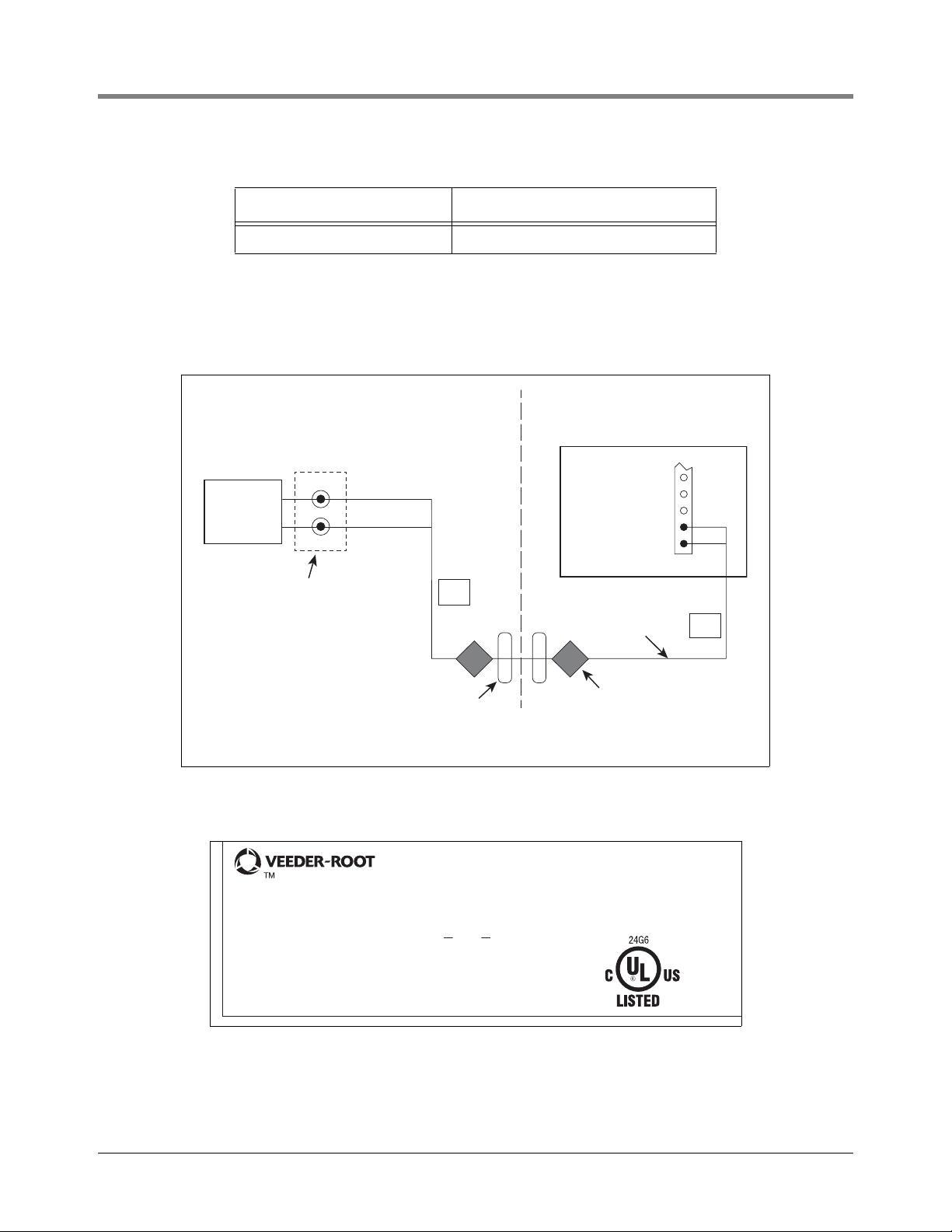
Product Marking Information
RELATED DOCUMENTS
Documents Required to Install Equipment
This intrinsically safe apparatus is only for use as part of a Veeder-Root Automatic Tank Gauging System (ATG
Console with probes and sensors). To install intrinsically safe apparatus, use the specific control drawing that
appears on the nameplate of the applicable associated apparatus (ATG Console):
1
Page 6
Introduction Product Marking Information
CLASS I Division 1, Group D
CLASS 1, Zone 0
Hazardous Location
Intrinsically Safe Apparatus
Non-Hazardous Location
Associated Apparatus
ATG Console
I.S. Sensor
Connections
DPLLD
Sensor
Intrinsically Safe
Wiring
White (+)
(+)
Black (-)
(-)
I.S.
Rigid Conduit
GENERAL PRODUCT WIRING DIAGRAM
Seal-Off
I.S.
Weatherproof
Junction Box
I.S. CIRCUIT FOR HAZLOC SENSOR
F/N 8590XX-XXX
S/N XXXXXX
-40°C < Ta < +60°C
CL I, DIV. 1, GP.D
CL I, ZONE 0
AEx ia IIA
Ex ia IIA
TC=T4
MANUAL NO. 577013-933
SECURITE INTRINSEQUE
Associated Apparatus
TLS-450PLUS&TLS-450/8600 331940-008
UL/cUL Control Drawing Number
The control drawings contain information related to the correct installation of the overall intrinsically Safe System.
This includes information such as maximum number of apparatus, specific apparatus allowed in the system,
maximum cable lengths, references to codes, proper grounding and so on. Control drawings can be found on the
accompanying Compact Disk (TECH DOCS CD) or on the INTERNET at veeder.com under SUPPORT; VR
TECHNICAL DOCUMENTS; DRAWINGS.
Product Label Contents
2
Page 7
Introduction Safety Warnings
OFF
NOTICE
Safety Warnings
To protect yourself and your equipment, observe the following warnings and important information:
WARNING
This product is to be installed in systems operating near locations where
highly combustible fuels or vapors may be present.
FAILURE TO COMPLY WITH THE FOLLOWING WARNINGS AND SAFETY
WARNING
PRECAUTIONS COULD CAUSE DAMAGE TO PROPERTY, ENVIRONMENT,
RESULTING IN SERIOUS INJURY OR DEATH.
1. Read and follow all instructions in this manual, including all safety
warnings to protect yourself and others from serious injury, explosion, or
electrical shock.
2. Comply with all applicable codes including: the National Electrical Code;
federal, state, and local codes; and other applicable safety codes.
3. To protect yourself and others from being struck by vehicles, block off
your work area during installation or service.
4. Do not alter or modify any component or substitute components in this
kit.
5. Warning! Substitution of components may impair intrinsic safety.
6. Field wiring to the DPLLD Transducer must not share a conduit with any
non-intrinsically safe device’s wiring.
7. To prevent ignition of flammable or combustible atmospheres, turn off,
tag and lockout power to console and pumps before servicing.
8. Before installing or taking the transducer into a hazardous area, earth the
unit in a safe area to remove any static charge. Then immediately
transport the unit to the installation site. Do not rub or clean the unit prior
to installation. Cleaning is not required under normal service conditions.
Do not rub or clean the unit after installation. If the unit is not fixed to a
known earth point when installed, ensure that a separate earth
connection is made to prevent the potential of a static discharge. When
fitting or removing the unit, use of anti-static footwear or clothing is
required.
9. Materials used in the construction of this device do not contain, by mass,
more than 10% in total of aluminum, magnesium, zirconium and titanium
or 7.5% in total of magnesium, titanium and zirconium.
Failure to install this product in accordance with its instructions and warnings will result in
voiding of all warranties with this product.
3
Page 8
Introduction Safety Symbols
OFF
G
A
S
WARNING
CAUTION
NOTICE
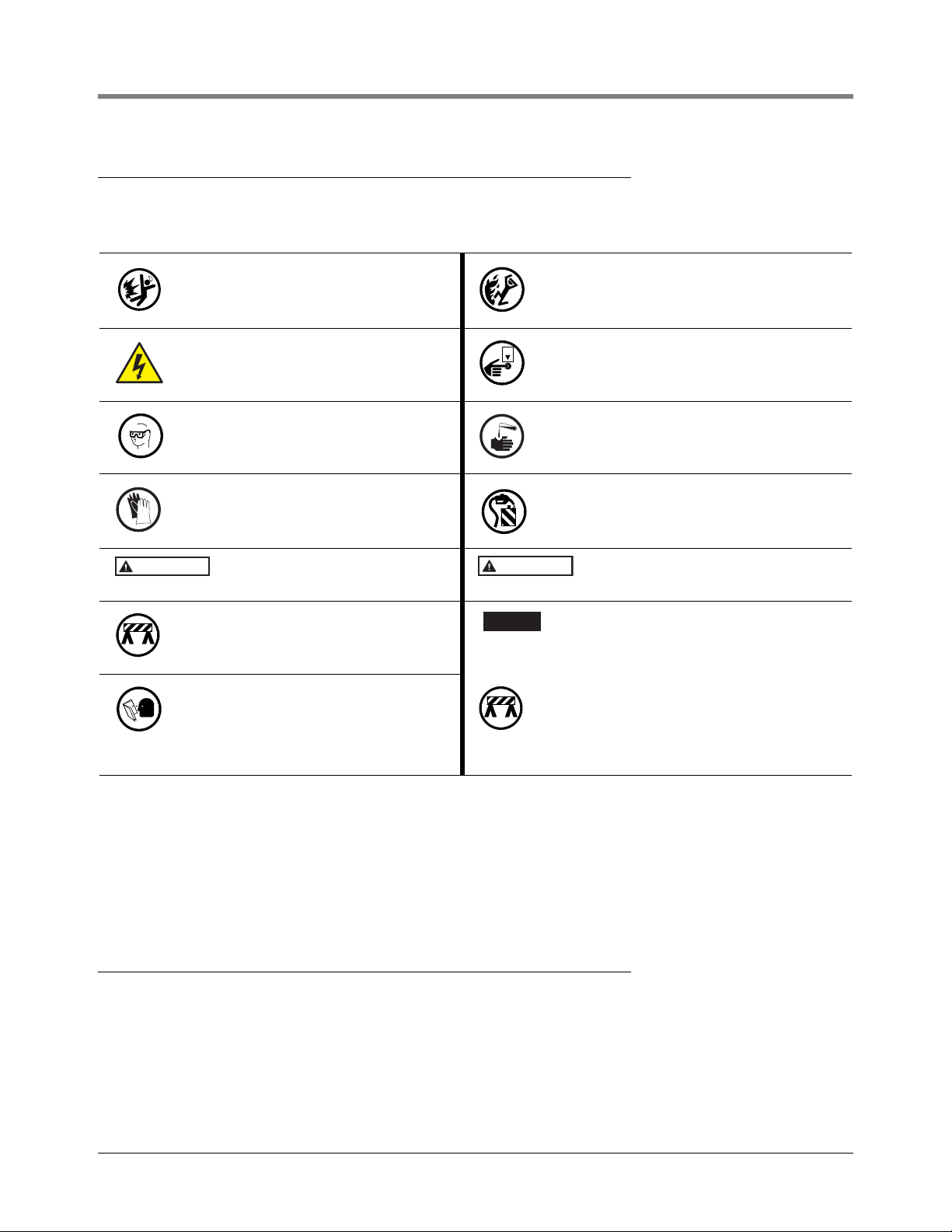
Safety Symbols
The following safety symbols may be used throughout this manual to alert you to important safety hazards and
precautions.
EXPLOSIVE
Fuels and their vapors are extremely explosive if ignited.
ELECTRICITY
High voltage exists in, and is supplied to,
the device. A potential shock hazard exists.
WEAR EYE PROTECTION
Fuel spray from residual pressure in the
lines can cause serious eye injuries.
Always wear eye protection.
GLOVES
Wear gloves to protect hands from irritation or injury.
WARNING indicates a hazardous situa-
tion which, if not avoided, could result in
death or serious injury.
USE SAFETY BARRICADES
Always use safety cones or barricades,
safety tape, and your vehicle to block the
work area.
READ ALL RELATED MANUALS
Knowledge of all related procedures
before you begin work is important. Read
and understand all manuals thoroughly. If
you do not understand a procedure, ask
someone who does.
FLAMMABLE
Fuels and their vapors are extremely flammable.
TURN POWER OFF
Live power to a device creates a potential
shock hazard. Turn Off power to the device and
associated accessories when servicing the unit.
INJURY
Careless or improper handling of materials can
result in bodily injury.
APPROVED CONTAINERSS
Use nonbreakable, clearly marked containers,
suitable for collecting and transporting hazardous fuels during service.
CAUTION indicates a hazardous situation
which, if not avoided, could result in minor or
moderate injury.
NOTICE is used to address practices not related
to physical injury.
USE SAFETY BARRICADES
Always use safety cones or barricades, safety
tape, and your vehicle to block the work area.
REFERENCE MANUALS
577013-465
577014-073
577013-879
Line Leak Application Guide
TLS-450PLUS Site Prep and Installation Manual
TLS-450 Console Site Prep and Installation Manual
Before You Begin
1. Ensure that the submersible turbine pump (STP) is properly grounded as per the manufacturer’s instructions.
2. A shutoff valve installed between the DPLLD transducer and the product pipeline is recommended. Al
not required
any product spill
for the DPLLD equipment to work, the valve will aid in troubleshooting the system and in reduci
age when performing service work in the sump.
4
though
ng
Page 9
Introduction Warning Tags
WARNING
WARNING
THE SUBMERGED PUMP SYSTEM SUPPLYING THE
DISPENSERS MAY TURN ON UNEXPECTEDLY TO
PERFORM A LINE LEAK TEST. THIS MAY RESULT
IN FUEL SPRAYING DURING DISPENSER, PRODUCT
LINE, LEAK DETECTOR OR STP SERVICE.
PERFORM THE FOLLOWING BEFORE BEGINNING SERVICE:
1. CLOSE AFFECTED DISPENSER SHEAR VALVE AND TEST
FOR PROPER SHUTOFF OF THE VALVE IF PERFORMING
DISPENSER HYDRAULIC SERVICE.
2. REMOVE POWER TO THE SUBMERGED PUMP (STP) AND
TO THE CONSOLE AND THE LINE LEAK DETECTOR SYSTEM.
3. WEAR EYE PROTECTION.
4. COLLECT FUEL IN APPROVED CONTAINERS.
DO NOT CONTAMINATE ENVIRONMENT.
TO ORDER TAGS - USE PART NO. 329801-001
consoles\warntag.eps
OFF
G
A
S
3. The SwiftCheck valve requires a 3” hex socket (or wrench) for tightening it in the pump’s leak detector port.
The non-vented SwiftCheck valve requires a 1-1/2” hex socket (or wrench) for tightening it in the pump’s leak
detector port.
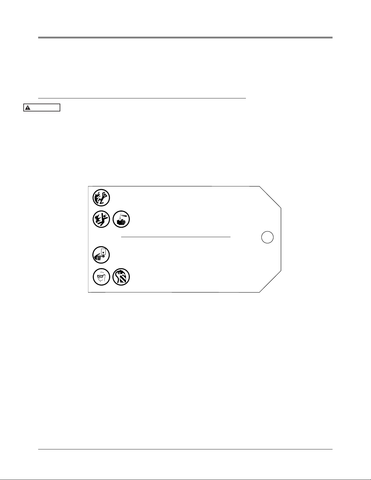
Warning Tags
Turn off, tag (using the warning tags provided), and lockout power to the console and submersible pumps while installing the DPLLD equipment. This will prevent either a dispense
attempt or the DPLLD equipment from automatically starting up the pump.
Warning tags [Figure 1] are provided with the DPLLD equipment. For your safety and the safety of others who may
service dispensers, submersible pumps, or DPLLD equipment, you must attach a tag to each of the following
devices where it can clearly be seen by a service person performing work on the system:
•Console
• Submersible pump
• Dispenser filter
Figure 1. Warning tag
5
Page 10

Site Considerations
Manholes
When using a SwiftCheck Valve, the manhole must provide at least 8 inches of clearance above the pump head to
install the DPLLD components.
Unused Piping Runs
Where piping runs have been installed for future use, but are connected to the active piping system, isolate the
inactive lines from the active lines using a shutoff valve. Failure to do so may harm system performance.
Existing Check Valves
You must ensure that there are no existing check valves already installed in the pipeline. The presence of any check
valve (other than the one used with the DPLLD equipment) can prevent the DPLLD equipment from detecting line
leaks in the area of pipeline downstream from the check valve.
Manifolded Product Lines
Follow these guidelines as you install a DPLLD equipment into multiple manifolded tanks:
• Dielectric unions and flexible piping elements should be used as required by federal, state, and local
requirements for the specific piping application. Location of unions may vary with configuration.
• An I/O Module in the console is required to control the pump on the higher-numbered tank and pump control
output for the primary tank, and the “Pump In” (Dispenser ON) signal for the set.
• A DPLLD transducer is only required in the master pump.
• Remove any other check valve or leak detect device in the line that is not shown.
• Refer to the Line Leak Application Guide for check valve requirements.
6
Page 11
DPLLD Equipment Overview
DPLLD Components
• TLS-450/TLS-450PLUS console with DPLLD feature.
• DPLLD pressure transducer (one for each product line monitored) - vented or non-vented check valves may be
required depending on pump type and application
• USM Module to monitor DPLLD transducers
• I/O Module to control site master and slave STPs
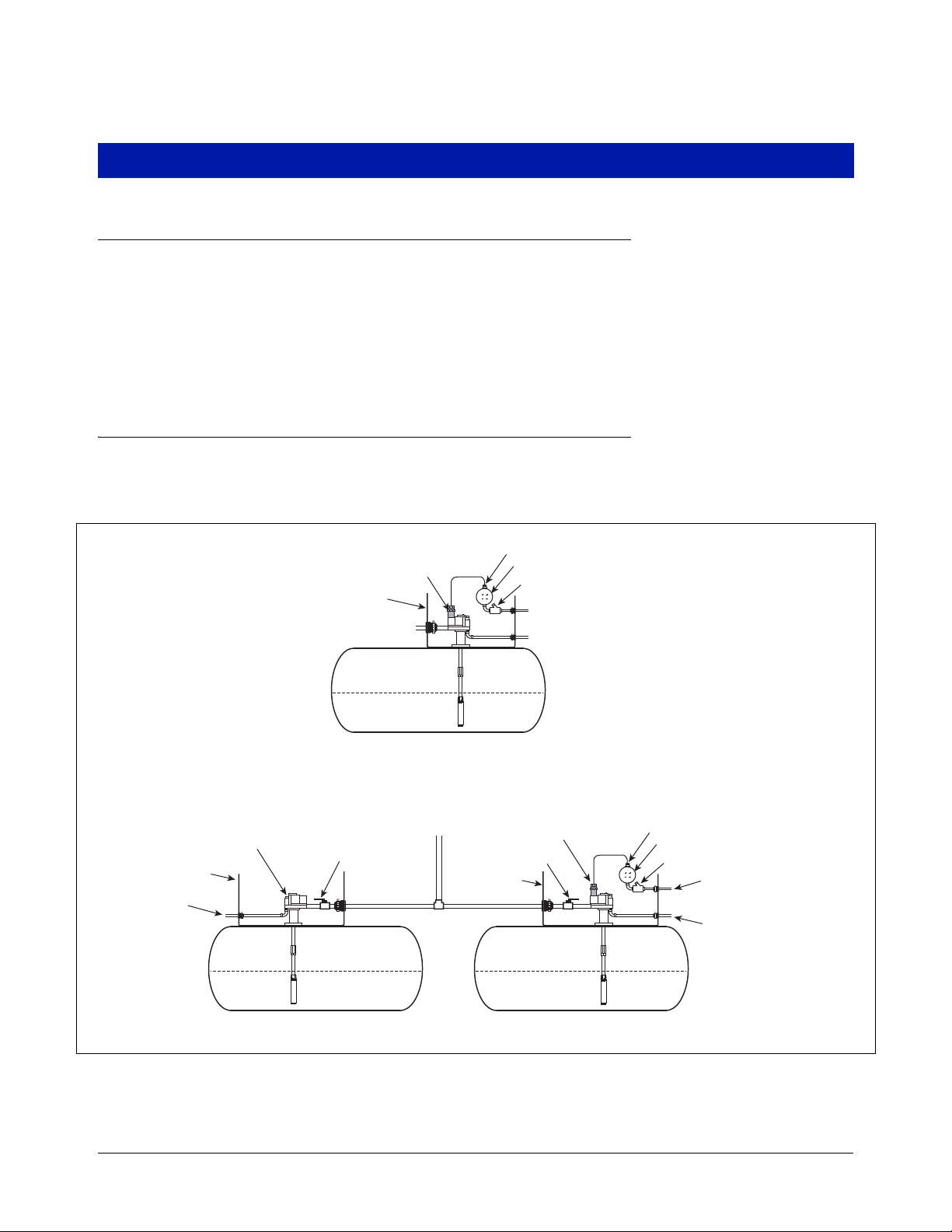
DPLLD Installation Example
Figure 2 shows an example DPLLD installation for a single tank and a manifolded tank set having Red Jacket
Standard pumps.
Non-vented SwiftCheck or
high pressure valve
To I/O module in
TLS console
( STP power)
Sump
To Dispensers
Shut-off valve
STP
DPLLD transducer and
SwiftCheck valve
Sump
SINGLE
To Dispensers
Cord grip
Junction box
Seal off
To USM module in TLS console (line pressure)
To pump control box
STP
DPLLD transducer and
SwiftCheck valve
Shut-off valve
Sump
Cord grip
Junction box
Seal off
To USM module
in TLS console ( line pressure)
To pump control box
STP
MASTERSLAVE
Figure 2. Example DPLLD Equipment Installation
7
dplld\plldoverview.eps
Page 12
DPLLD Transducer Installation
OFF
WARNING
WARNING
This section discusses DPLLD transducer installation for the following DPLLD approved pumps:
• Red Jacket Standard and Quantum pumps - DPLLD transducer/SwiftCheck valve (page 8)
• Red Jacket Standard and Quantum pumps - DPLLD transducer/Pressurstat (page 12)
• Red Jacket Quantum with SpikeCheck Valve (page 13)
• The Red Jacket (page 14)
• Red Jacket Maxxum Big-Flo (page 15)
• FE-Petro (page 16)
Red Jacket Standard and Quantum Pumps (DPLLD w/SwiftCheck)
Use this installation procedure to install a DPLLD transducer with a SwiftCheck valve in a Red Jacket Standard or
Quantum pump.
Disconnect, lock out, and tag all AC power to the TLS console, dispensers and submersible pumps.
When servicing equipment, use non-sparking tools and use caution when removing or installing equipment to avoid generating a spark.
1. If a ball valve is installed down line from the pump, close it.
2. Do one of the following:
a. If the submersible turbine pump is equipped with a mechanical LLD, remove the mechanical unit and any
related tubing and fittings, or
b. If the submersible turbine pump is not equipped with a mechanical LLD, remove the 2-inch mechanical
LLD port plug.
3. Ensure that the sealing surface for the SwiftCheck valve’s external o-ring is smooth and free from corrosion,
pitting, and any material build-up [Figure 3].
Failure to ensure a smooth seal surface can result in false line leak alarms.
8
Page 13

DPLLD Transducer Installation Red Jacket Standard and Quantum Pumps (DPLLD w/SwiftCheck)
Sealing surface
of pump port
Pressurstat
(adjustable
functional
element)
Functional element
(non-adjustable type)
OR
DPLLD
Sensor
SwiftCheck
Valve
pumps\drdjkswfv.eps
Figure 3. Sealing Surface For SwiftCheck Valve’s External O-Ring (With Both Functional Element Types Identified)
4. Lubricate the external o-ring on the SwiftCheck valve using mineral oil or other suitable lubricant.
5. If there is a Stage II vapor recovery device installed, go to Step 7. If there is no Stage II vapor recovery, install
the SwiftCheck valve [Figure 4] in the mechanical LLD pump port. Thread the DPLLD transducer into the
SwiftCheck Valve.
WARNING
Do not overtighten the SwiftCheck valve when installing it into the pump. Over tightening the valve can cause a flow restriction in the line!
WARNING
Seal the NPT threads only with a UL-Classified, nontoxic pipe sealant suitable for the
fuel involved (for high-alcohol fuel blend applications, Loctite 564 is recommended).
Apply sealant in a manner that prevents it from entering and contaminating hydraulic
cavities.
Figure 4. DPLLD Transducer Installation
9
Page 14

DPLLD Transducer Installation Red Jacket Standard and Quantum Pumps (DPLLD w/SwiftCheck)
6. If there is a Stage II vapor recovery device installed in the pressurized piping you must install the SwiftCheck
valve into a Red Jacket leak detector fitting (P/N 038-072) as shown in Figure 5 instead of in the pump’s leak
detector port. Because the DPLLD transducer must be installed downstream from these devices, a monitored
containment sump is required.
WARNING
There must not be a check valve installed between the SwiftCheck valve and the pump
for DPLLD to function properly.
Ensure that the Healy pump is wired according to the manufacturer’s instructions and utilizes isolation relays.
Lubricate the external o-ring on the SwiftCheck valve using mineral oil or other suitable lubricant and thread
the valve into the Red Jacket fitting.
TM
Submersible
pump
Healy
Mini-Jet
Waterproof
junction box
Containment
sump
to TLS
console
Sump
sensor
Note: remove inline check valve,
if present
Figure 5. DPLLD Install W/Healy Mini-Jet System (Required Dielectric Union And Shutoff Valve Not Shown)
DPLLD sensor
SwiftCheck valve
Red Jacket leak
detector fitting
(Red Jacket Part#
038-072)
to TLS
console
Product line
to dispensers
plld\dhealy.eps
7. Thread the DPLLD transducer into the SwiftCheck valve (ref. Figure 4 or Figure 5 as appropriate).
WARNING
Seal the NPT threads only with a UL-Classified, nontoxic pipe sealant suitable for the fuel involved (for high-alcohol fuel blend applications, Loctite 564 is recommended). Apply sealant
in a manner that prevents it from entering and contaminating hydraulic cavities.
8. Get a watertight cord grip from the transducer installation kit and coat its 1/2” NPT threaded end with ULClassified, nontoxic pipe sealant suitable for the fuel involved. Screw the cord grip into one of the openings in
the weatherproof junction box. Feed the end of the DPLLD transducer cable through the cord grip and then
tighten the nut to ensure a watertight seal. Connect and seal the pressure transducer wires to the wires from
the TLS console as described in ‘Epoxy Sealing DPLLD Transducer Field Wiring Connections’ on page 20.
9. The DPLLD SwiftCheck valve eliminates the need for the pump’s Pressurstat or functional element relief valve
so it must be modified as part of the DPLLD equipment installation. Remove the six 1/4-28 slot-head screws
from the Pressurstat or functional element [Figure 6].
10. Remove the spring, piston and diaphragm.
11. Carefully reassemble the Pressurstat or functional element using a new diaphragm suitable for the fuel
involved. Be sure that all mating surfaces are free from debris when reinstalling.
10
Page 15

DPLLD Transducer Installation Red Jacket Standard and Quantum Pumps (DPLLD w/SwiftCheck)
Remove spring & piston
Pressurstat DPLLD/SwiftCheck
Functional
element
Replace gasket
pumps\dRDJKSWFVfelem.eps
OR
12. Torque the six slot-head screws to 40-65 in-lbs.
13. Open the ball valve down line from the pump.
WARNING
Failure to properly reseal the Pressurstat or functional element may
result in product leakage, which could create serious environmental
and safety hazards.
Fire, explosion, or ground contamination could occur.
Carefully reassemble and reseal the Pressurstat or functional
element, following the procedures described in this manual.
Figure 6. Modifying The Pressurstat/Functional Element In Red Jacket Pumps
11
Page 16

DPLLD Transducer Installation Red Jacket Standard and Quantum Pumps (DPLLD w/Pressurstat)
OFF
WARNING
pumps\dpresstatplld.eps
Pressurstat
(adjustable
functional
element)
DPLLD
transducer
Red Jacket Standard and Quantum Pumps (DPLLD w/Pressurstat)
Use this installation procedure to install a DPLLD transducer in a Red Jacket Standard or Quantum pump that has
a Pressurstat that will be used for leak detection. NOTE: This installation method is approved for 3.0 gph testing
only and cannot be used if there is a Stage II vapor recovery device installed in the pressurized piping.
Disconnect, lock out, and tag all AC power to the TLS console, dispensers and submersible pumps.
When servicing equipment, use non-sparking tools and use caution when removing or
installing equipment to avoid generating a spark.
1. If a ball valve is installed down line from the pump, close it.
2. Do one of the following:
a. If the submersible turbine pump is equipped with a mechanical LLD, remove the mechanical unit and any
related tubing and fittings, or
b. If the submersible turbine pump is not equipped with a mechanical LLD, remove the 2-inch mechanical
LLD port plug.
3. Thread the DPLLD transducer into the LLD port (Figure 5).
WARNING
4. Get a watertight cord grip from the transducer installation kit and coat its 1/2” NPT threaded end with ULClassified, nontoxic pipe sealant suitable for the fuel involved. Screw the cord grip into one of the openings in
the weatherproof junction box. Feed the end of the DPLLD transducer cable through the cord grip and then
tighten the nut to ensure a watertight seal. Connect and seal the pressure transducer wires to the wires from
the TLS console as described in ‘Epoxy Sealing DPLLD Transducer Field Wiring Connections’ on page 20.
5. Open the ball valve down line from the pump.
Seal the NPT threads only with a UL-Classified, nontoxic pipe sealant suitable for the
fuel involved (for high-alcohol fuel blend applications, Loctite 564 is recommended).
Apply sealant in a manner that prevents it from entering and contaminating hydraulic
cavities.
Figure 7. PLLD/Pressurstat Installation
12
Page 17

DPLLD Transducer Installation Red Jacket Quantum Pumps with SpikeCheck Valve
OFF
WARNING
WARNING
Red Jacket Quantum Pumps with SpikeCheck Valve
Disconnect, lock out, and tag all AC power to the TLS console, dispensers and submersible pumps.
When servicing equipment, use non-sparking tools and use caution when removing or
installing equipment to avoid generating a spark.
1. If a ball valve is installed down line from the pump, close it.
2. If the pump does not have a Stage II vapor recovery device installed in the pressurized piping, do one of the
following:
a. If the submersible turbine pump is equipped with a mechanical LLD, remove the mechanical unit and any
related tubing and fittings, or
b. If the submersible turbine pump is not equipped with a mechanical LLD, remove the 2-inch mechanical
LLD port plug.
3. Thread the DPLLD transducer directly into the mechanical LLD port on the pump (see Figure 8).
WARNING
Seal the NPT threads only with a UL-Classified, nontoxic pipe sealant suitable for the
fuel involved (for high-alcohol fuel blend applications, Loctite 564 is recommended).
Apply sealant in a manner that prevents it from entering and contaminating hydraulic
cavities.
plld/dquantumpvr.eps
DPLLD
transducer
SpikeCheck Valve Assy.
Figure 8. DPLLD Installation In Red Jacket Quantum Pumps (W/ SpikeCheck Valve Assy.)
4. If the pump does have a Stage II vapor recovery device installed in the pressurized piping remove the
mechanical LLD unit and any related tubing and fittings if present and plug the ports.
Lubricate the external o-ring on the SwiftCheck valve using mineral oil or other suitable lubricant and thread
the valve into the Red Jacket leak detector fitting (P/N 038-072) as shown in Figure 5 on page 10 instead of
in the pump’s leak detector port. Next thread the DPLLD transducer into the SwiftCheck valve.
Seal the NPT threads only with a UL-Classified, nontoxic pipe sealant suitable for the
fuel involved (for high-alcohol fuel blend applications, Loctite 564 is recommended).
Apply sealant in a manner that prevents it from entering and contaminating hydraulic
cavities.
Because the DPLLD transducer must be installed downstream from these devices, a monitored containment
sump is required.
13
Page 18

DPLLD Transducer Installation The Red Jacket Pump
WARNING
OFF
WARNING
DPLLD transducer installs
in line leak detector port
plld\dvsfcplld.eps
There must not be a check valve installed between the SwiftCheck valve and the pump
for DPLLD to function properly.
Ensure that the Healy pump is wired according to the manufacturer’s instructions and utilizes isolation relays.
5. Get a watertight cord grip from the transducer installation kit and coat its 1/2” NPT threaded end with ULClassified, nontoxic pipe sealant suitable for the fuel involved. Screw the cord grip into one of the openings in
the weatherproof junction box. Feed the end of the DPLLD transducer cable through the cord grip and then
tighten the nut to ensure a watertight seal. Connect and seal the pressure transducer wires to the wires from
the TLS console as described in ‘Epoxy Sealing DPLLD Transducer Field Wiring Connections’ on page 20.
6. Open the ball valve down line from the pump.
The Red Jacket Pump
The DPLLD transducer mounts directly into the line leak detector pump port. It eliminates the need to break
product lines for installation and service.
Since the DPLLD transducer replaces the existing mechanical device, it is suitable in applications where there is
no sump.
Disconnect, lock out, and tag all AC power to the TLS console, dispensers and submersible pumps.
When servicing equipment, use non-sparking tools and use caution when removing or
installing equipment to avoid generating a spark.
1. If a ball valve is installed down line from the pump, close it.
2. If the pump does not have a Stage II vapor recovery device installed in the pressurized piping, remove the 2’’
NPT plug from line leak detector port. Install the DPLLD transducer into the 2’’ NPT port (see Figure 9).
WARNING
Seal the NPT threads only with a UL-Classified, nontoxic pipe sealant suitable for the
fuel involved (for high-alcohol fuel blend applications, Loctite 564 is recommended).
Apply sealant in a manner that prevents it from entering and contaminating hydraulic
cavities.
Figure 9. Locating Discharge Port Plug For Line Leak Transducer
3. If the pump does have a Stage II vapor recovery device installed in the pressurized piping, lubricate the
external o-ring on the SwiftCheck valve using mineral oil or other suitable lubricant and thread the valve into
the Red Jacket leak detector fitting (P/N 038-072) as shown in Figure 5 on page 10 instead of in the pump’s
leak detector port. Next thread the DPLLD transducer into the SwiftCheck valve.
14
Page 19

DPLLD Transducer Installation Red Jacket Maxxum Big-Flo
WARNING
OFF
WARNING
DPLLD transducer
in 2" Transducer
port
Seal-off, epoxy seal per NFPA spec
(customer supplied)
conduit to console
(customer supplied)
Junction box
(customer supplied)
WARNING
Seal the NPT threads only with a UL-Classified, nontoxic pipe sealant suitable for the
fuel involved (for high-alcohol fuel blend applications, Loctite 564 is recommended).
Apply sealant in a manner that prevents it from entering and contaminating hydraulic
cavities.
Because the DPLLD transducer must be installed downstream from these devices, a monitored containment
sump is required.
There must not be a check valve installed between the SwiftCheck valve and the pump
for DPLLD to function properly.
Ensure that the Healy pump is wired according to the manufacturer’s instructions and utilizes isolation relays.
4. Get a watertight cord grip from the transducer installation kit and coat its 1/2” NPT threaded end with ULClassified, nontoxic pipe sealant suitable for the fuel involved. Screw the cord grip into one of the openings in
the weatherproof junction box. Feed the end of the DPLLD transducer cable through the cord grip and then
tighten the nut to ensure a watertight seal. Connect and seal the pressure transducer wires to the wires from
the TLS console as described in ‘Epoxy Sealing DPLLD Transducer Field Wiring Connections’ on page 20.
5. Open the ball valve down line from the pump.
Red Jacket Maxxum Big-Flo
Disconnect, lock out, and tag all AC power to the TLS console, dispensers and submersible pumps.
When servicing equipment, use non-sparking tools and use caution when removing or
installing equipment to avoid generating a spark.
1. If a ball valve is installed down line from the pump, close it.
2. If any in-line check valves or Big-Flo Diaphragm Valve are installed in the line, they must be removed.
3. Remove the cap from the 2-inch Transducer port next to the 3-inch discharge port. Thread the DPLLD
transducer into the transducer port (see Figure 10).
WARNING
Seal the NPT threads only with a UL-Classified, nontoxic pipe sealant suitable for the
fuel involved (for high-alcohol fuel blend applications, Loctite 564 is recommended).
Apply sealant in a manner that prevents it from entering and contaminating hydraulic
cavities.
Figure 10. Example DPLLD Installation In A Red Jacket Maxxum Big-Flo Pump
15
Page 20

DPLLD Transducer Installation FE Petro Pumps
OFF
WARNING
4. Get a watertight cord grip from the transducer installation kit and coat its 1/2” NPT threaded end with ULClassified, nontoxic pipe sealant suitable for the fuel involved. Screw the cord grip into one of the openings in
the weatherproof junction box. Feed the end of the DPLLD transducer cable through the cord grip and then
tighten the nut to ensure a watertight seal. Connect and seal the pressure transducer wires to the wires from
the TLS console as described in ‘Epoxy Sealing DPLLD Transducer Field Wiring Connections’ on page 20.
5. Open the ball valve down line from the pump.
FE Petro Pumps
Disconnect, lock out, and tag all AC power to the TLS console, dispensers and submersible pumps.
When servicing equipment, use non-sparking tools and use caution when removing or installing equipment to avoid generating a spark.
1. If a ball valve is installed down line from the pump, close it.
2. If the pump does not have a Stage II vapor recovery device installed in the pressurized piping, remove the 2’’
NPT plug from line leak detector port.
Install the DPLLD transducer into the 2’’ NPT port as shown in Figure 11.
WARNING
Seal the NPT threads only with a UL-Classified, nontoxic pipe sealant suitable for the
fuel involved (for high-alcohol fuel blend applications, Loctite 564 is recommended).
Apply sealant in a manner that prevents it from entering and contaminating hydraulic
cavities.
3. If the pump does have a Stage II vapor recovery device installed in the pressurized piping, lubricate the
external o-ring on the SwiftCheck valve using mineral oil or other suitable lubricant and thread the valve into
the Red Jacket leak detector fitting (P/N 038-072) as shown in Figure 5 on page 10 instead of in the pump’s
leak detector port. Next thread the DPLLD transducer into the SwiftCheck valve.
WARNING
Seal the NPT threads only with a UL-Classified, nontoxic pipe sealant suitable for the
fuel involved (for high-alcohol fuel blend applications, Loctite 564 is recommended).
Apply sealant in a manner that prevents it from entering and contaminating hydraulic
cavities.
Because the DPLLD transducer must be installed downstream from these devices, a monitored containment
sump is required.
WARNING
There must not be a check valve installed between the SwiftCheck valve and the pump
for DPLLD to function properly.
Ensure that the Healy pump is wired according to the manufacturer’s instructions and utilizes isolation relays.
4. For DPLLD operation there must be a FE Petro model R precision check valve in the pump, If necessary,
replace the current check valve with a model R precision check valve (ref. Figure 11).
16
Page 21

DPLLD Transducer Installation FE Petro Pumps
pumps\dfeptp.eps
Manifold
cover
Check valve
spring
FE Petro O-ring
Part No. 400211238 or 400333238
Model R
Precision
check valve
DPLLD transducer
Valve clamp
(should be snug
up against cover)
Pressure Test Port - remove plug to access
valve clamp adjustment screw. Turn screw
CCW until valve clamp is all the way up and
snug against manifold cover.
plld\fervlv. eps
"R" stamp
R
R
Black ID nut
Top View
Bottom View
Figure 11. Location of DPLLD Transducer And Model ‘R’ Precision Check Valve In FE Petro Pump
5. Get a watertight cord grip from the transducer installation kit and coat its 1/2” NPT threaded end with ULClassified, nontoxic pipe sealant suitable for the fuel involved. Screw the cord grip into one of the openings in
the weatherproof junction box. Feed the end of the DPLLD transducer cable through the cord grip and then
tighten the nut to ensure a watertight seal. Connect and seal the pressure transducer wires to the wires from
Figure 12. Identifying A FE Petro ‘R’ Style Precision Check Valve
the TLS console as described in ‘Epoxy Sealing DPLLD Transducer Field Wiring Connections’ on page 20.
6. Open the ball valve down line from the pump.
FE PETRO HIGH CAPACITY PUMPS
When installing PLLD in a FE Petro High Capacity pump, a FE Petro Model ‘R’ Relief Valve (P/N 401330902)
must be installed in the pump. Refer to the manufacturer’s documentation to verify that this relief valve is present. If
the ‘R’ relief valve is not present install as per manufacturer’s instructions.
17
Page 22

DPLLD Transducer Installation FE Petro Pumps
NOTICE
You will also need to install a reducing tee (customer supplied) in the 3-inch discharge port of the pump with the 2inch opening facing up. Thread the PLLD transducer into the 2-inch opening of the tee.
WARNING
Seal the NPT threads only with a UL-Classified, nontoxic pipe sealant suitable for the
fuel involved (for high-alcohol fuel blend applications, Loctite 564 is recommended).
Apply sealant in a manner that prevents it from entering and contaminating hydraulic
cavities.
FE PETRO VARIABLE SPEED PUMP SYSTEM MODIFICATIONS
The FE Petro variable speed pump system contains a submersible pump and adjustable frequency drive. For
satisfactory operation with the DPLLD System, you need to change the following in the adjustable frequency drive
as described below:
• Dip switch (SW2) settings
• Rotary switch positions
WARNING
IST-VFC Software Versions 1.1 and 1.2
The settings and positions depend on the software version of the FE Petro IST-VFC (Intelligent Submersible
Turbine-Variable Speed Controller). To determine the software version of the IST-VFC, remove its cover and check
the label on the FE Petro chip, which is on the printed circuit board. The instructions below are for Version 1.1 and
1.2 of the IST-VFC.
Dip Switch SW2
Pole 1 on dip switch SW2 (Figure 13) controls the pump start up time. Set this switch to OFF so that the
submersible pump will run at 34 psi for 6 seconds each time it is started. Pole 2 does not affect DPLLD operation;
it sets the product type for the IST-VFC (ref. Table 1).
.
The correct hardware and switch settings must be used for the system to detect leaks
less than 3.0 gph. If the correct hardware and switch settings are not used, the system
will always pass 0.1 gph tests, but the passing results will be invalid.
Table 1. FE-IST-VFC Product Type Dip Switch (SW2) Settings
Pole 1 Pole 2
OFF (required) ON-gasoline, OFF-diesel
Rotary Switch
The rotary switch (Figure 13) controls the pump pressure of the submersible pump. As shown in Table 2, use
positions 1, 2, 3, or 4 to run the pump at a pressure range compatible with DPLLD operation.
Do not use positions 0, 5, 6, 7, 8, or 9 with versions 1.1 or 1.2 software.
18
Page 23

DPLLD Transducer Installation FE Petro Pumps
1234
SW2
5
0
1
23
4
5
6
7
8
9
pumps\feptrvsp.eps
Dip switch
Rotary switch
Figure 13. Dip Switch SW2 And Rotary Switch Locations In The FE-Petro IST-VFC Unit
Table 2. FE-IST-VFC Rotary Switch Positions W/V1.1/1.2 Software
Position Pressure (psi)
126
228
330
432
IST-VFC Software Version 1.3
The settings for software version 1.3 are the same as versions 1.1 and 1.2, except that the rotary switch can be
set to any position from 1 to 9.
19
Page 24

DPLLD Field Wiring
NOTICE
OFF
WARNING
NOTICE
Black
White
Epoxy sealed connections in a
weatherproof junction box
To
USM
Module
From
DPLLD
Transducer
1/2'' rigid
conduit
Seal-off
WARNING
Refer to the appropriate Site Prep manual (P/N 577014-073 - TLS-450PLUS or P/N 577013879 TLS-450) for required wiring types/lengths for pressure transducer and pump control
field wiring.
DPLLD Transducers
1. Pull a shielded, 2-conductor cable from each DPLLD transducer’s sump junction box to the appropriate USM
module in the TLS console. NOTE: The transducer is an intrinsically safe device and its wiring must not share
a conduit with any non-intrinsically safe device.
Disconnect, lock out, and tag all AC power to the TLS console,
dispensers and submersible pumps.
2. Using wire nuts, connect the white and black wires from the DPLLD transducer to field wires in the
weatherproof sump junction box (ref. Figure 14). Be sure to maintain correct polarity between the color-
coded or marked field wires and DPLLD transducer wires when making all connections. Cut off
the transducer shielded ground wire (if present) flush with the cable jacket. Do the same for the
cable shield.
The shielded cable drain wire must be connected to the ground lug in the intrinsically safe
area of the console, not to the transducer!
Figure 14. Field Connections Of DPLLD Transducer
3. Seal wire nut connections using the epoxy sealant furnished with each transducer. Use one packet for no more
than two wire nut connections. Ensure the end of the cable jacket is submerged in the epoxy. Refer to
Figure 15 as you prepare epoxy and seal connections.
Do not put more than two wire nut connections in one epoxy sealant bag or the connections will not be properly sealed. Improper sealing of the connections will result in
inaccurate system readings and possibly false alarms.
20
Page 25

DPLLD Field Wiring DPLLD Transducers
consoles\epxy2w.eps
To console
Tie wrap
Wire nuts
From probe,
sensor, or
transducer
ACB
Make sure that
the ends of cable
sheathing are submerged in sealant
Instructions:
NOTE: When temperature is below 50˚F (10˚C), keep
resin in a warm place prior to mixing (e.g., in an
inside pocket next to body).
1. Open epoxy sealant package, and remove resin pak.
2. Holding resin pak as shown in A, bend pak along long
length.
3. As shown in B, firmly squeeze the RED SIDE of the
resin, forcing it through the center seal and into
BLACK SIDE.
4. Mix thoroughly to a uniform color by squeezing
contents back and forth 25-30 times.
5. Squeeze mixed, warm resin into one end of bag and
cutoff other end.
6. Slowly insert wiring connections into sealing pack
until they fit snugly against the opposite end as
shown in C.
7. Twist open end of bag and use tie wrap to close it off
and position the tie wrapped end up until the resin
jells.
CAUTION: Epoxy sealant is irritating to eyes, respiratory system,
and skin. Can cause allergic skin reaction. Contains: epoxy resin
and Cycloaliphatic epoxycarboxylate.
Precautions: Wear suitable protective clothing, gloves, eye, and
face protection. Use only in well ventilated areas. Wash
thoroughly before eating, drinking, or smoking.
Figure 15. Epoxy Sealing Pressure Transducer Field Connections
21
Page 26

DPLLD Wiring Connections In the Console
NOTICE
OFF
WARNING
Observe polarity
DPLLD transducer
White (+)
Black (-)
dplldwir.eps
USM Module
WARNING
DPLLD Transducer Wiring Connections
• Be sure all wires are color-coded or carefully marked to identify their source and to maintain polarity.
Once a connector has been wired to a module and the console has been programmed, the
connector and module cannot be moved to another slot without reprogramming the system.
• Record the location (e.g., Line #1 (regular), Line #2 (super), etc.) of each DPLLD transducer on the circuit
directory inside the right-hand console door.
Disconnect, lock out, and tag all AC power to the TLS console, dispensers and submersible pumps.
1. Connect the two color-coded or marked wires from each DPLLD transducer to the USM module. (see
Figure 16). Maintain correct polarity between the color-coded or marked field wires and the connector
terminals during wiring.
2. Connect the transducer cable’s bare wire (shield) to one of the ground lugs in the TLS console.
Pump Wiring Connections
The console must be able to detect when dispensers are switched On or Off so it only initiates line leak tests
when the dispenser is switched Off. The console must also be able to start the submersible pump to perform a line
leak test, and shut off the pump if a leak is detected.
Figure 16. DPLLD Transducer Wiring To USM Module
Dispensers and TLS console must be wired to the same leg of incoming power at the
main electrical panel; otherwise damage to both may result.
The console, when wired correctly, will control the pump independent of the dispenser
control circuits. It is imperative that when the emergency stop switch is wired and tested, the console’s pump control circuitry CANNOT start up the pump. To ensure that the
pumps are unable to be activated in an emergency situation, have the emergency stop
switch interrupt pump power at the circuit breaker panel via shunt breakers.
22
Page 27

DPLLD Wiring Connections In the Console Pump Wiring Connections
OFF
WARNING
PUMP INPUT
PUMP OUTPUT
PUMP RETURN (NEUTRAL)
PUMP CONTROL FROM SELF SERVE
SYSTEM OR DISPENSER
SWITCHED HOT (120 VAC)
RED JACKET
REMOTE
CONTROL BOX
PRODUCT
RELAY
CIRCUIT BREAKER
PANEL
TO
SUBMERSIBLE
PUMP
FROM
BREAKER
PANEL
PUMP POWER
L1
120 OR 240 VAC LINE
N
AC NEUTRAL
S2
M2 M1 N L1 L2
I/O Module
Disconnect, lock out,
and tag power at the
power panel before
wiring the pump.
WARNING
OFF
Make ground connection in
accordance with local codes.
NOTICE
Disconnect, lock out, and tag all AC power to the TLS console, dispens-
WARNING
ers and submersible pumps.
1. Referring to the appropriate wiring diagrams below, pull the necessary number of #14 AWG color-coded or
marked copper wires from STP control boxes, self-serve system/dispenser, and power panel to the
appropriate I/O module of the TLS console. Since wiring for multiple pump controls may be entering the
console through the same conduit opening,
color code or mark each wire to identify its source!
The dispensers and TLS console must be wired to the same leg of incoming power at
the main electrical panel; otherwise damage may result to dispensers and console.
2. DPLLD pump control wiring varies depending on the pump manufacturer’s relay control box. Refer to the
appropriate wiring diagram example below to connect DPLLD controlled pumps to the I/O Module in the TLS
console (circuit diagrams are for switched ‘hot’ dispensers):
• Red Jacket (ref. Figure 17, Figure 18, and Figure 19)
• Non-Red Jacket (ref. Figure 20)
• Manifolded tanks (ref. Figure 21, Figure 22, and Figure 24)
• Gilbarco dispenser isolation box (ref. Figure 22)
Figure 17. DPLLD Pump Control Diagram For Red Jacket Relay Control Box
23
Page 28

DPLLD Wiring Connections In the Console Pump Wiring Connections
LINE
1
230V
N
115
LINE
2
ORANGE
ORANGE
BLACK
WHITE
WHITE
WHITE
STARTING RELAY
STARTING
CAPACITOR
RUNNING
CAPACITOR
OVERLOAD RELAY
RESET BUTTON
CONTACTOR
CONTACTOR COIL
TERMINALS
1
5
2
T3
L3
L2
L1
T1 T2
WHITE
ORANGE
RED
RED
RED
BLK
115V
COIL
RED
BLACK
BLACK
BLACK
BLUE
BLUE
BLACK
Start
Stop
BLACK
RED
RED
BLUE
BLUE
MOTOR
BLUE
BLUE
1
2
3
EXT
PILOT
115V EXTERNAL
PILOT LIGHT
(50 WATT MAX.)
Thermal
Overload
115
Control Box Relay
Note: The control
box relay must be
a 115 Vac STP relay
Circuit Breaker Panel
Pump control from
self-service system
or dispenser switched
hot 115 Vac
AC Line
115 Vac
AC Neutral
Pump Return (PR)
Pump Return (PR)
Pump Out (PO)
Pump In (Pi)
Line In (LI)
I/O Module
Disconnect, lock out,
and tag power at the
power panel before
wiring the pump.
WARNING
OFF
Make ground connection in
accordance with local codes.
NOTICE
Figure 18. Red Jacket Maxxum Big-Flo Single-Phase Wiring
24
Page 29

DPLLD Wiring Connections In the Console Pump Wiring Connections
L1 L2 L3
T1 T2 T3
COIL
To ext. pilot
light 115V
supply
Note: Observe color code
L1, L2, L3 phase sequence
for proper rotation of motor
Red
Orange
Black
Blue
Thermal
Overload
Blue
208/230V, 3-Phase
Power Supply
208/230V, 3-Phase
Power Supply
Black
Pump Return (PR)
Pump In (PI)
Line In (LI)
Control Box Relay
Circuit Breaker Panel
Pump Out (PO)
Pump control from
self-service system
or dispenser switched
hot 115 Vac
AC Line 115 Vac
AC Neutral
(AC Neutral)
I/O Module
Disconnect, lock out,
and tag power at the
power panel before
wiring the pump.
WARNING
OFF
Make ground connection in
accordance with local codes.
NOTICE
Figure 19. Red Jacket Maxxum Big-Flo 3-Phase Wiring
25
Page 30

DPLLD Wiring Connections In the Console Pump Wiring Connections
Pump Contactor
Pump
Motor
Pump Motor
Power
120 or 240 Vac Line
15 Amp Max.
AC Neutral
L1
Pump Return (Neutral)
Pump Input
Pump Control from Self Serve
System or Dispenser Switched
Hot 120 or 240 Vac
N
I/O Module
Disconnect, lock out,
and tag power at the
power panel before
wiring the pump.
WARNING
OFF
Make ground connection in
accordance with local codes.
NOTICE
Figure 20. DPLLD pUmp Control Diagram For Non-Red Jacket Relay Control Box
26
Page 31

DPLLD Wiring Connections In the Console Pump Wiring Connections
L1
N
S2 M2 M1 N L1 L2
S2 M2 M1 N L1 L2
Product
Relay
Product
Relay
TO
SUBMERSIBLE
PUMP
PUMP CONTROL
FROM SELF-SERVE SYSTEM
OR DISPENSER
SWITCHED HOT (120 VAC)
RED JACKET
REMOTE
CONTROL BOX
FROM
BREAKER PANEL
PUMP POWER
TO
SUBMERSIBLE
PUMP
120 or 240 VAC LINE
AC NEUTRAL
15 AMP MAX
FROM
BREAKER PANEL
PUMP POWER
Slave Pump
RED JACKET
REMOTE
CONTROL BOX
PUMP INPUT
PUMP RETURN (NEUTRAL)
PUMP OUTPUT
Master Pump
Circuit Breaker Panel
I/O Module
Disconnect, lock out,
and tag power at the
power panel before
wiring the pump.
WARNING
OFF
Make ground connection in
accordance with local codes.
NOTICE
Figure 21. Wiring Diagram - Manifolded Lines DPLLD - Multiple Tanks (RJ Relay Control Box Shown In This Example)
27
Page 32

DPLLD Wiring Connections In the Console Pump Wiring Connections
Pump Output
Pump Input
Pump Input attaches to P.I. terminal
and Pump Output wire attaches
to P.O. terminal for the specific pump
(in this example Pump 1)
Dispenser 2
Dispenser 3
Dispenser 4
Dispenser 5
Dispenser 6
Dispenser 7
Dispenser 8
Hot TB1
PI
L1 L2
NPO
T1
T2
L1 N L2 M1M2PO PI
Gilbarco
Dispenser
Isolation Box
(PA02870000000)
Relay
Board
Relay
Neutral
TB2
PUMP CONTROL
From Dispenser 1
Switched Hot (120 Vac)
L1
120 or 240 VAC LINE
15 AMP MAX
Circuit Breaker Panel
N
AC NEUTRAL
Remove jumper between
PO and PI terminals*
Pump
Motor
*For sites without line leak
detection,a jumper wire will be
installed between PO and PI
terminals. This jumper wire
comes installed from Gilbarco
and must be removed when
wiring in line leak pump control
wiring.
I/O Module
Disconnect, lock out,
and tag power at the
power panel before
wiring the pump.
WARNING
OFF
Make ground connection in
accordance with local codes.
NOTICE
Figure 22. DPLLD Pump Control Diagram For Gilbarco Dispenser Isolation Box
28
Page 33

DPLLD Wiring Connections In the Console Pump Wiring Connections
Set pole 3 on (SW2)
to Off for Slave
WAR NI NG
OFF
Disconnect, lock out,
and tag power at the
power panel before
wiring the pump.
IST-VFC
(Factory Default)
SLAVE
Software version must
be 1.5 or higher
Set Pressure Select (SW1)
to same position for all units
(Ditto for Master below)
Pump Input (PI)
I/O Module
1234567
Set all switches of Serial
Address (SW3 to
master-Slave (M-S)
configuration per Table 5 of
IST-VFC Installation
Owner's Manual
Communication cable
Pump Return (PR)
Dispenser
Hook Signal
(120 Vac)
IST-VFC
Pump Output (PO)
MASTER
Circuit Breaker Panel
L1
120 or 240 VAC LINE
15 AMP MAX
N
AC NEUTR AL
NOTICE
Make ground connection in
accordance with local codes.
1234567
Figure 23. Manifolded Product Lines - Dual FE Petro IST-VFC Controllers
Set pole 3 on (SW2)
to On for Master
Software version must
be 1.5 or higher
29
Page 34

DPLLD Wiring Connections In the Console Pump Wiring Connections
C23
Z2
Z3
#1
TO PUMP
SHLDCOM+ COM-
TB1
C23
D2 D1 M2 M1 L2L1
GND
Z3
Z2
IQ2
IQ1
230VAC
N
L1
N
DISPENSER HOOK
PUMP OUTPUT IQ1
N
TO PUMP
#2
230VAC
PUMP OUTPUT IQ2
NO C
VR RELAY
COM +
IQ2
COM +
IQ1
SHIELD
RS-485
COMMUNICATION
CABLE
COM -
I/O Module
Disconnect, lock out,
and tag power at the
power panel before
wiring the pump.
WARNING
OFF
Make ground connection in
accordance with local codes.
NOTICE
SHLDCOM+ COM-
TB1
D2 D1 M2 M1 L2L1
GND
Figure 24. Manifolded Product Lines - Dual Red Jacket IQ Controllers
30
Page 35

DPLLD Equipment Checkout
WARNING
OFF
WARNING
WARNING
Do not switch On power to the console. This must be done by an Authorized Service
Contractor during the warranty checkout and start-up procedure! An Authorized Service Contractor must program the DPLLD set-up information into the console before
beginning these DPLLD equipment checks.
Repeat the four steps below for each DPLLD monitored line.
1. VENT THE LINE
WARNING
Disconnect, lock out, and tag all AC power to the TLS console, dispensers and submersible pumps.Turn Off, lock out, tag power to the STP.
When servicing equipment, use non-sparking tools and use caution when removing or installing equipment to avoid generating a spark.
a. Vent the line to zero.
b. Reseal the line.
c. Turn On power to the STP.
If the pump has a functional element or PressurStat, verify that it is not leaking!
2. RED JACKET STANDARD, QUANTUM, AND MAXXUM PUMPS WITH DPLLD TRANSDUCER
AND PRESSURSTAT ONLY
You MUST reset the Pressurstat’s relief pressure as part of the DPLLD installation.
a. Unscrew the protective brass cap from the adjustment screw (Figure 25).
b. When the adjustment screw is fully down, the relief pressure is approximately 40 psi.
c. Install a pressure gauge in the line.
d. Set the relief pressure to 20 - 25 psi (verify the relief pressure by using the console - [refer to “5. Enable
the Line for Dispensing” on page 32 for the procedure to obtain pressure readings]).
e. Check the sealing surface for the cap’s o-ring and the condition of the o-ring. Clean or replace as required.
f. Replace the brass cap and hand tighten (the o-ring completes the seal between the body and cap).
31
Page 36

DPLLD Equipment Checkout Pump Wiring Connections
Brass Cap
Adjustment Screw
O-ring
pumps\rjfeadjplld.eps
Figure 25. Pressurstat Adjustable Valve Assembly (Red Jacket Standard Pump Shown)
3. DETERMINE DPLLD TRANSDUCER PRESSURE OFFSET
New transducers are now factory sealed and their internal chamber cannot be equalized to atmospheric pressure
by opening a vent screw as in the past. The Pressure Offset test procedure described in this step MUST be
performed when using new DPLLD transducers with serial numbers of 100,000 or above, in sites located at
altitudes above 2,000 feet. Note: this procedure can also be used with transducers having serial numbers below
100,000 instead of using the vent screw to equalize pressure.
Before this procedure is performed, the pressure in the line MUST be vented to zero. It is recommended that this
procedure be performed after installing the transducer, before energizing the STP. Consult the TLS-450 console’s
online help to perform the following steps:
• Run Pressure Offset Test
• Enter the Pressure Offset Value for the DPLLD Transducer
4. PURGE AIR FROM THE LINE
Follow accepted procedures, or appropriate pump manual, to purge all air from the product line being enabled for
dispensing.
5. ENABLE THE LINE FOR DISPENSING
After completing the DPLLD installation, the console will not enable dispensing from a line until a 3.0 gph test on
the line has been passed. In this step, as you run the required 3.0 gph test, you will also verify that the Pump On
and Pump Off pressures are within their proper operating ranges.
32
Page 37

For technical support, sales or
other assistance, please visit:
www.veeder.com
 Loading...