

Page 1
Introduction
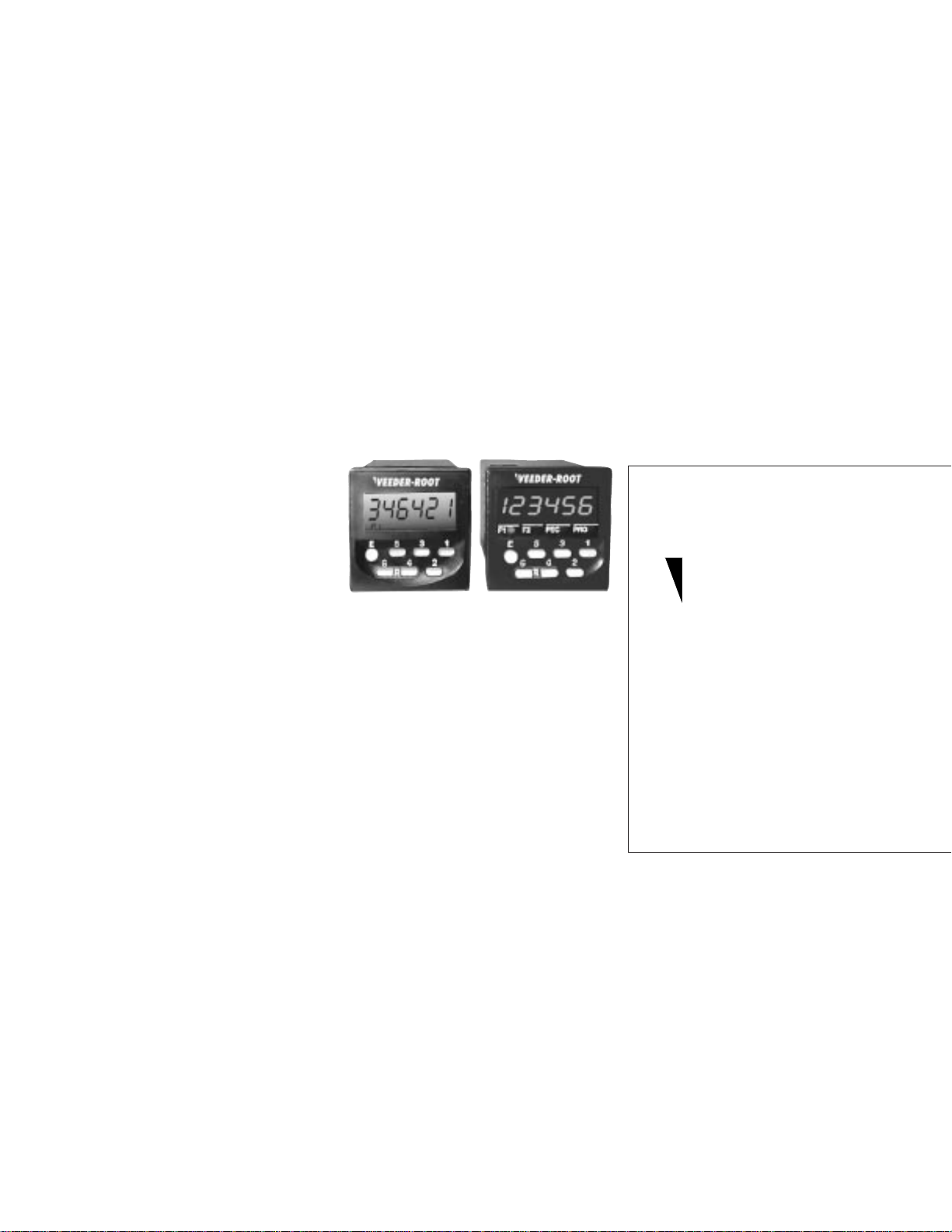
The Veeder-Root brand C346 family offers a new level of performance in a 1/16 DIN
instrument. Fully programmable to operate as a preset counter, a rate meter (with
outputs) or an elapsed time counter. Enhanced fuctionality provides operating
modes for batching, background totalizing, and operation as dual counters with
master sum. When used as an elapsed time counter, the C346 offers unique
functionality for measurement of pulse widths or time between pulses. The C346 is
available with an LCD display or the industry's only 6 digit LED display for a 48mm
x 48mm product.
A wide variety of features are present that enable use in even the most demanding
applications. Inputs can be accepted from both NPN or PNP sensors, dry contacts or
encoders, and the input scaling function enables rate and count inputs to be
displayed in engineering units. Single and dual preset models are available and
each preset offers both a transistor output, which can interface to an external SSR
or PLC, and a relay output for
directly driving a load. The outputs
can be programmed for latching or
timed operation.
Even with a high level of
functionality, simplicity of operation
is still maintained. Important
parameters such as the preset and
prescale values can be called up
quickly with direct access keys
while an intuitive button per digit
interface enables those values to be changed easily.
The C346 has a NEMA 4 rated faceplate is CE approved, and UL and CUL listed.
Technical Manual
701996-0000
Veeder-Root
C346
brand
Features
• Choice of 6 digit LED or LCD Display
• Button Per-Digit setting and direct access
keys for easy opertation
• Field programmable for operation as a
preset counter, batch counter, rate meter
or elapsed time meter, all with outputs
• Input scale function for display in
engineering units
• Add/Subtract, Add/Add and quadrature
input modes
• Background count value keeps track of
production totals
• 12 - 24 VDC sensor power supply
• Accepts either NPN or PNP inputs
• Relay and transistor outputs for each
preset
• Reset via front panel, remote input or
automatically
• NEMA 4 rated front panel
Index
Overview
Operation
Programming
General
Construction page 2
Terminal Connections page 2
Panel Mounting page 3
Front Panel page 4
Setup/Oper. Overview page 4
Operation Mode page 5
Basic Functionality page 8
Counter Mode page 8
Rate Meter Mode page 11
Elapsed Time Mode page 13
Dual Register Mode page 16
Batch Counter Mode page 17
Specifications page 19
Ordering Information page 20
Warranty page 20
Preset Counter
Rate Meter
Time Counter
Page 2
OVERVIEW
PROGRAMMING
CONSTRUCTION
Compact Design
Standard 1/16 DIN (48mm x 48mm) faceplate
VEEDER-ROOT
346421
P1
E 5 3 1
6
REAR TERMINAL CONNECTIONS
17 16
4 2
6 4 2
R
15
14 13 12 11 10
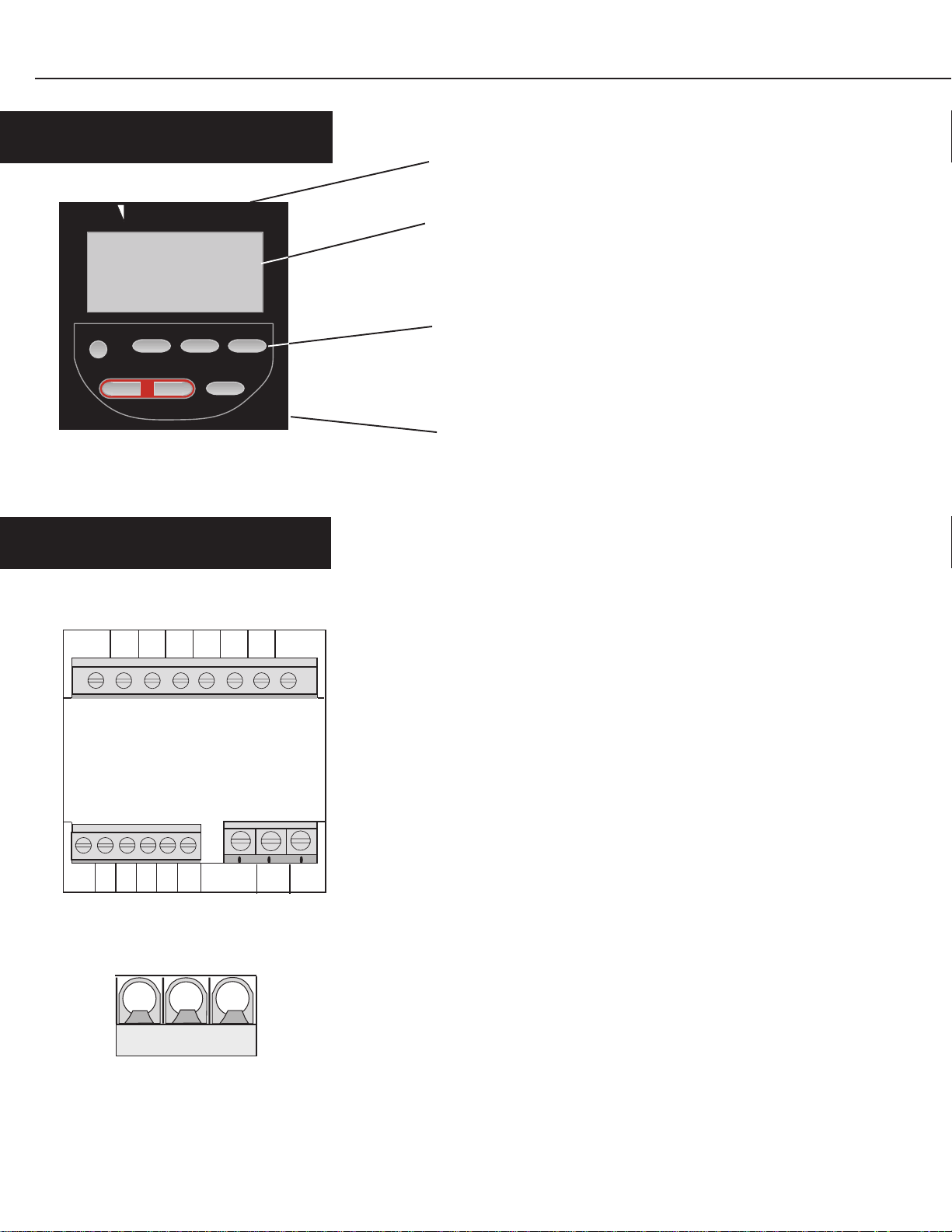
Main Display
Can be toggled quickly between count value, set value and
prescale value. LCD and LED display models available.
Simple Button per Digit Programming
A dedicated button for each of the 6 decades available in the
Preset value enables quick changes. The Edit key allows
quick access to important parameters.
Front Panel Seal
NEMA 4/IEC IP65 front panel for use in washdown environments
1. Sensor Power Supply - Provides 12 -24 VDC for powering of
external sensors up to 50 ma.
Note: For DC powered version, this terminal is used for the positive
input of the DC supply
2. Common - For use with sensor power supply, Inputs A, B, & C, and
transistor outputs 1 and 2
3. Input A- Programmable as the primary count input or channel A for
an encoder input
4. Input B - Programmable to be a directional input, an inhibit input, a
decrementing input, an incrementing input, or channel B of an
encoder input
35612 7 8 94
Top View of Terminals
Insert wire into opening and turn the screw
to tighten the wire clamp.
2
5. Input C - Programmable for use as a reset input or an inhibit input
6. Transistor Output 1 - Provides a PNP open collector output signal
when Preset 1 is activated
7. Relay Output 1 - Normally closed contact
8. Relay Output 1 - Normally open contact
9. Relay Output 1 - Common
10. AC Power Input - Neutral (Not connected for DC powered units)
11. AC Power Input - Line (Not connected for DC powered units)
12. Do Not Connect
13. Transistor Output 2 - Provides a PNP open collector output signal
when Preset 2 is activated
14. Do Not Connect
15. Relay Output 2 - Normally closed contact
16. Relay Output 2 - Normally open contact
17. Relay Output 2 - Common
Page 3
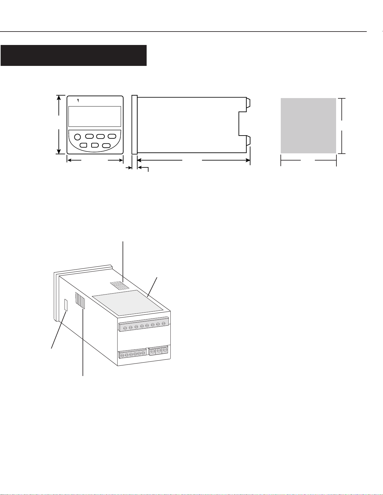
PANEL MOUNTING
123456
48mm
Release Slot
Side Mounting
VEEDER-ROOT
48mm
Grooves
Dimensions
8mm
Top Mounting
Grooves
Wiring Diagram
Panel Cutout
45mm
93mm
45mm
Make cutout(s) based on the recommended panel opening
illustrated in the drawing above.
Place the unit in the panel and slide the included gasket
over the rear of the unit. Make sure the unit is positioned
squarely against the panel and the gasket is not distorted.
Orient the bracket so that the tabs are pointing away from
the panel. Slide the bracket over the unit so that the tabs
catch in the grooves on the housing, and the bracket is as
far forward as possible. Use the panel mount screws to
tighten the bracket until there is a secure seal against the
gasket.
Please note that there are 4 sets of grooves on the housing
so that the bracket can be positioned with the screws on
the top or the side.
The electronic components of the instrument can be
removed from the housing. To do so the bracket must be
loosened and slid back until the release slot on each side is
showing. Place a small screw driver in the release slot and
gently push forward. Repeat the procedure on the release
slot on the other side. The front panel and PCBs should
then be able to be pulled forward out of the housing.
3
Page 4
OPERATION
PROGRAMMING
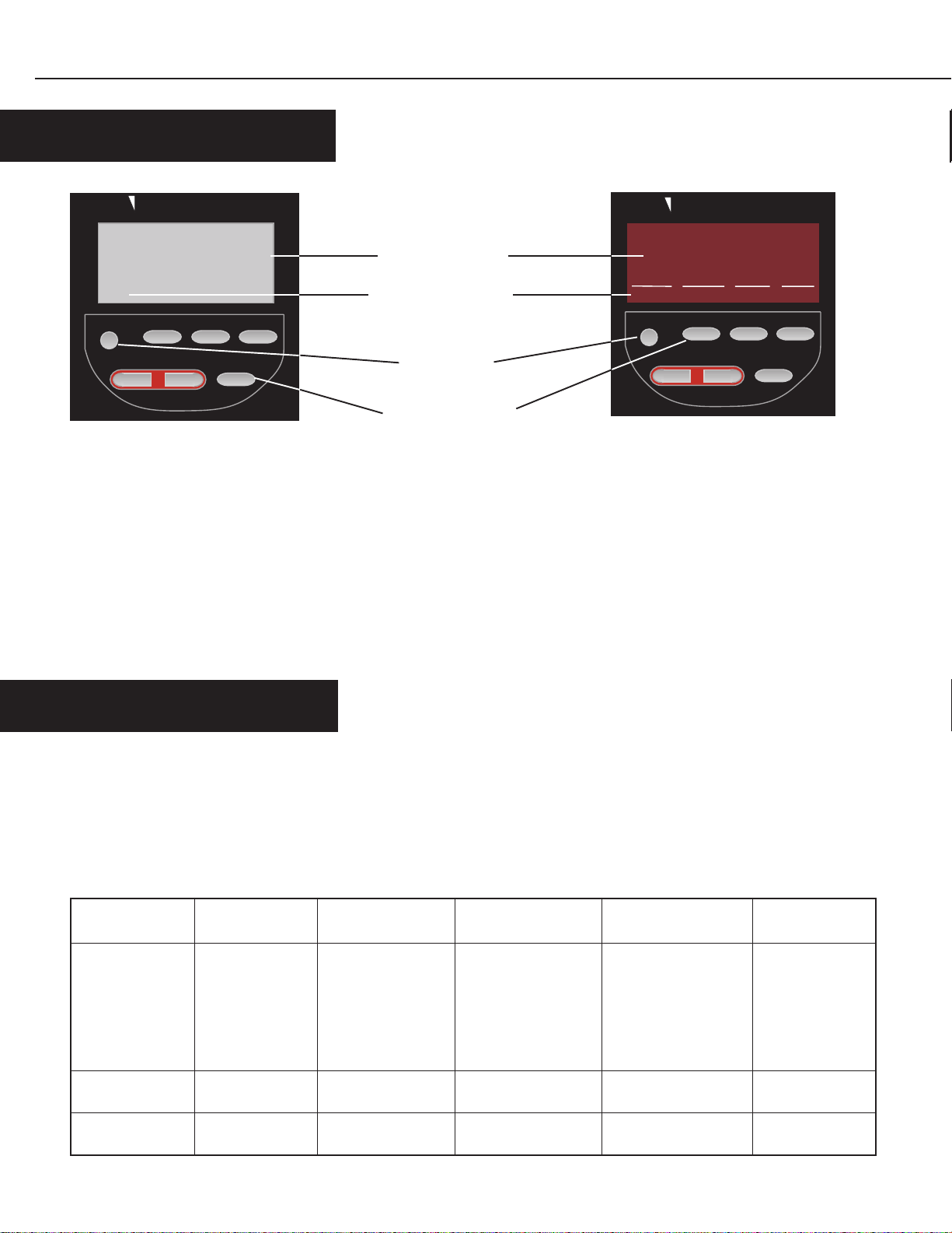
FRONT PANEL
LCD Version LED Version
VEEDER-ROOT
1. Main Display
346421
P1
E 5 3 1
6 4 2
6 4 2
R
1. Main Display: In Operating mode indicates the present
count, rate or time value. Can also be quickly toggled through
use of the Edit key to indicate the Preset Value or the Prescale
Value. In Program mode, this display indicates the parameter
code on the left side of the display, and the present parameter
value on the right side.
2. Status Displays: Indicates Preset 1 (F1), Preset 2 (F2),
Prescale, (PSC) and Program (PRG). In Operating mode, F1 and
F2 illuminate to indicate the active output(s). In Program
Mode, PRG is illuminated, and either F1, F2 or PSC is lit to
indicate which value is being displayed.
2. Status Displays
3. Edit Key
4. Numeric Keys
3. Edit Key: Can be used with the Numeric Keys 1, 2 and 3 in
Operation Mode to display Preset 1, Preset 2, and Prescale value
respectively. To Enter the Program Mode, depress the Edit key
during power-up and continue to hold for 5 secs. Once in
Program Mode, the Edit key is used to advance from one
parameter to the next.
4. Numeric Keys: Each of the numeric keys is used to
increment the value of the respective digit of the Preset(s) or
Prescale Value . When pressed simultaneously, the "6" and "4"
keys serve as a front panel reset.
VEEDER-ROOT
346421
F1 F2 PSC
E 5 3 1
6 4 2
R
PRG
SETUP/OPERATION OVERVIEW
Mode Decision: Your Series C346 is a powerful control
instrument that can be setup to operate in one of 5 modes:
1. Carefully review the following mode descriptions and choose
the Basic Functionality that best suits the application per the
procedure on page 8.
2. Once the mode is selected, it can be customized per the
Setup procedure on the page designated by the table below.
Mode:
Functionality
Follow
procedure on
page 8
Setup Page
Number:
Count Rate Time Dual Register Batch
1 or 2 preset
counter.
Background
Rate indicator
with 2 alarm
limits
totalizer
feature
8
11
3. Since each mode programs and operates in a manner that is specific
to its function, the table below lists the appropriate Operation page
number.
Operation
Page Number:
3
5
1 or 2 preset
timer
13
6
Two seperate
totalizing counters
(A, B) with third
counter providing
sum (A+B)
16
6
Preset counter
with
presettable
batch counter.
Batch total
display
17
7
4
Page 5
OPERATION
COUNT MODE OPERATION
In Operation Mode, the default display is the Count Value. The
Presets and Prescale Value can be accessed by simultaneously
pressing the Edit key and the appropriate Numeric key. The
Numeric keys are then used to alter the value. It is necessary to
then press the Edit key to confirm the change and return to the
Count Value display
123456
E
Edit Preset 1
12
123456
F1 PRG
351
62
4
Change Value
654321
E
Confirm Change
RATE MODE OPERATION
E
Edit Preset 2
123456
F2 PRG
351
642
Change Value
654321
F1 PRGF1 PRG
E
Confirm Change
E
Edit Prescaler
642
Change Value
F1 PRG
Confirm Change
3
000
8.
PSC PRG
351
456
0.
E
E
Background Total
4
123456
F1 F2
E
Return to Count Value
Note: The new value must be
confirmed by pressing the Edit key
within 15 seconds.
E
Edit Preset 1
12
123456
F1 PRG
351
62
4
Change Value
654321
E
Confirm Change
123456
E
Edit Preset 2
123456
F2 PRG
351
642
Change Value
654321
F1 PRGF1 PRG
E
Confirm Change
E
Edit Prescaler
642
Change Value
F1 PRG
Confirm Change
3
000
8.
PSC PRG
351
456
0.
E
Note: The new value must be
confirmed by pressing the Edit key
within 15 seconds.
5
Page 6
OPERATION
PROGRAMMING
TIME MODE OPERATION
123456
E
Edit Preset 1
123456
F1 PRG
62
4
Change Value
654321
Confirm Change
12
123456
351
642
654321
F1 PRGF1 PRG
E
DUAL REGISTER MODE OPERATION
E
Edit Preset 2
F2 PRG
351
Change Value
E
Confirm Change
E
Background or Batch Total
4
123456
F1 F2
E
Return to Count Value
Note: The new value must be
confirmed by pressing the Edit key
within 15 seconds.
E
Sub Total A
12
123456
F1 PRG
123456
E
Sub Total B
123456
F2 PRG
E
Edit Prescaler
642
Change Value
F1 PRG
Confirm Change
3
000
8.
PSC PRG
351
456
0.
E
Note: The new value must be
confirmed by pressing the Edit key
within 15 seconds.
6
Page 7

BATCH MODE OPERATION
123456
E
Edit Preset 1
12
123456
F1 PRG
351
62
4
Change Value
654321
E
Confirm Change
RESET OPERATION
E
Edit Preset 2
123456
F2 PRG
351
642
Change Value
654321
F1 PRGF1 PRG
E
Confirm Change
E
Edit Prescaler
642
Change Value
F1 PRG
Confirm Change
Reset operation (panel reset and remote input) is dependent on
the operating mode setup of the C346. The following table
describes reset operation of the instrument's 5 operating modes.
3
000
8.
PSC PRG
351
456
0.
E
E
Batch Total
123456
F1 F2
Return to Count Value
Note: The new value must be
confirmed by pressing the Edit key
within 15 seconds.
4
E
Mode:
Panel Reset
64
Resets count
value if
displayed
Remote Reset
(Input C)
Resets count
at any time
Count Rate Time Dual Register Batch
No reset
function
Resets time
value if
displayed
Resets
Sub Total A or
Sub Total B if
Resets count
or batch value
if displayed
displayed
No reset
function
Resets time
at any time
Resets
both Sub
Totals and
Resets count
value (not
batch count)
Primary counts
7
Page 8

PROGRAMMING
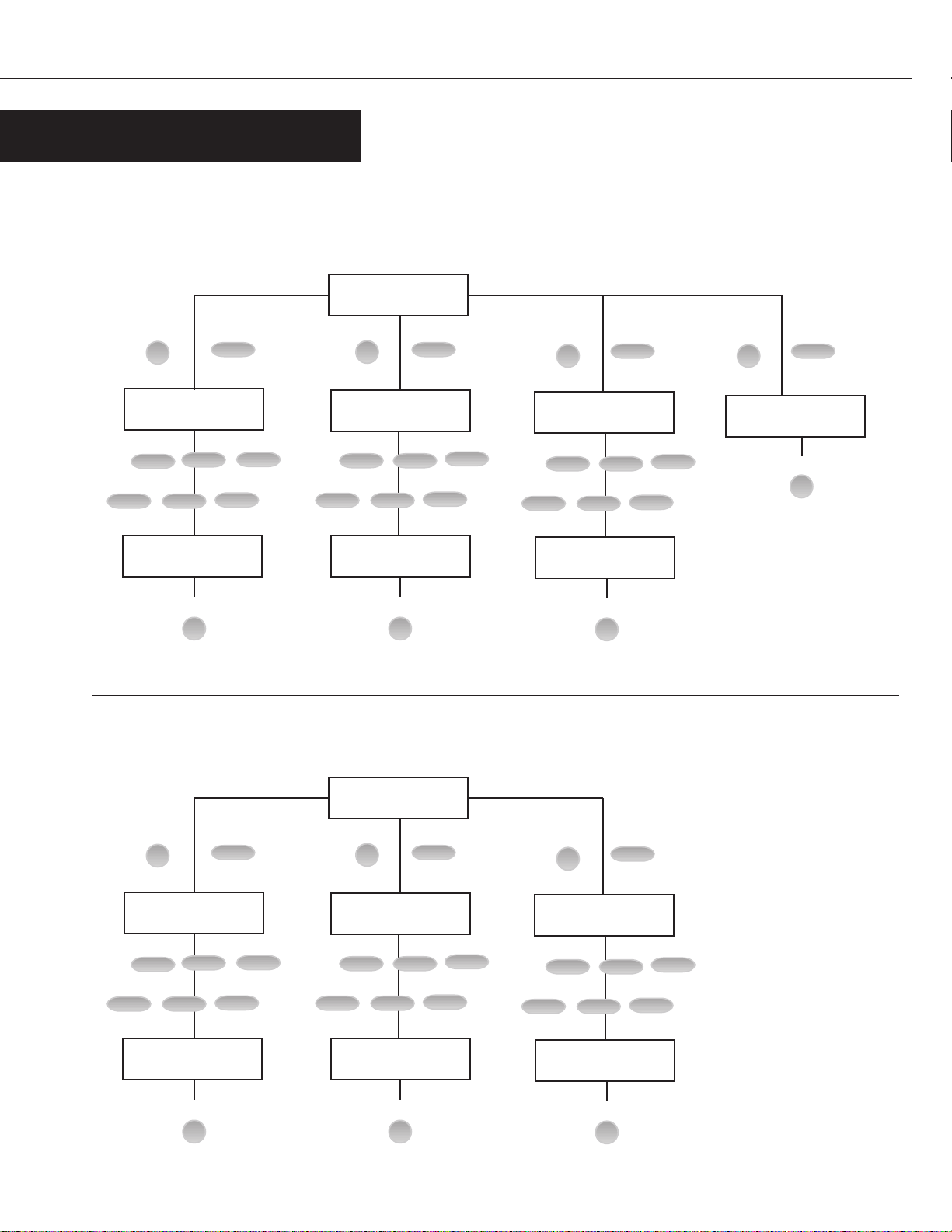
BASIC FUNCTIONALITY
The C346 can be programmed in the field to operate as a Preset Counter, a Rate Meter,
Elapsed Time Counter, Dual Register or Batch Counter. The default is Preset Counter. To
change the function hold down the both the Edit key and the "6" key during power-up. Use
the "1" key to scroll through the 5 choices as shown below.
E
6
FN
During Power-up
Counter Function
1
FN
Dual Register Function
COUNTER PROGRAMMING MODE
E
During Power-up
F0
5
0
PRG
E
PRG
PRG
F0 Default Settings: Changing this value from 0 to 1 will set all parameters back to their default values. A
setting of 0 has no effect on the other parameters.
0
3
1
FN
Rate Meter Function
1
FN
Batch Counter Function
If the functionality has been set to FN0, then the unit will operate as a preset counter. To
enter the Program mode, hold down the Edit key and the "5" key during power-up. Use the
Edit Key to move from one parameter to the next, and the "1" key to scroll though the
parameter choices. Holding down the Edit key for 5 seconds will return the unit to
Operation mode.
1
PRG
4
PRG
1
FN
Time Counter Function
E
2
PRG
F1
E
F3
E
F4
E
F6
8
0
PRG
0
PRG
0
PRG
0.10
PRG
F1 Count Mode: Defines the functionality of the 3 inputs. The choices are:
Code Input A Input B Input C
0 Count Input Inhibit Reset
1 Count Input Direction (U/D) Reset
2 Count Input Direction (U/D) Inhibit
3 Incrementing Decrementing Reset
4 Incrementing Decrementing Inhibit
5 Incrementing Incrementing Reset
6 Channel A Channel B Reset
7 Channel A Channel B Inhibit
F3 Display Decimal Point: Defines the number of digits displayed to the right of the decimal point for the
Count and Preset values. Settable in a range from 0 to 3.
F4 Reset Operation: Defines how the count value will behave when the preset is reached. Choices are:
0 Reset to "0", no Autoreset
1 Reset to "0", Autoreset
2 Reset to Preset, no Autoreset
3 Reset to Preset, Autoreset
F6 Output 1 Time: Sets the amount of time Output 1 will be active once the Preset is reached. Choices are:
Off No output
On Latching output (for dual presets, output 2 will deactivate output 1 )
0.02 20 ms
0.05 50 ms
0.10 100 ms
0.50 500 ms
1.00 1 sec.
Page 9

F7
0
PRG
E
F7 Output 2 Time: Sets the amount of time Output 2 will be active after the Preset is reached. Choices
are the same as Output 1
F9
F10
F11
F12
.10
PRG
E
1
PRG
E
1
PRG
E
0
PRG
E
F9 Output on Reset: When set to ON (1), the primary output (Output 2 on dual preset version) will
activate when the unit is reset.
F10 Input Type: Enables the unit to be programmed to work with either sinking or sourcing inputs.
Choices are NPN (0), and PNP (1)
F11 Count Speed: Enables the unit to be set for full speed of 5 kHz (1) or to 30 Hz (0) to provide debounce
filtering for contact inputs.
F12 Static/Dynamic Reset: When set to static reset (0) counting stops on the leading edge of the reset
input and does not resume until the trailing edge. When set to dynamic reset (1) the Count Value is
immediately reset on the leading edge of the reset signal, and will accumulate while the reset signal is still
active.
F14
F15
F20
0
PRG
E
0
PRG
E
0
PRG
E
F14 Output Signal Memory: Determines if after power interruption the outputs will resume their state
prior to the loss of power (1) or if the output will be reset (0)
F15 Background Totalizer: Setting this parameter to ON (1) will activate the totalizer function.
F20 Front Panel Reset Enable: When active (0), the count value and output(s) can be reset by
simultaneously pressing the "6" and "4" keys. If set to Off (1), reset can only take place through the
remote input, or through the front panel by holding the "6" and "4" keys for 10 seconds (see F29).
9
Page 10

PROGRAMMING
F21
F22
F23
F29
0
PRG
E
0
PRG
E
0
PRG
E
0
PRG
F21 Preset 1 Access Enable: When active (0), the Preset 1 value can be accessed by simultaneously
holding down the Edit key and the "1" key. If set to inactive (1), Preset 1 can not be accessed, or only
accessed by holding down the Edit key and the "1" key for 10 seconds (see F29)
F22 Preset 2 Access Enable: When active (0), the Preset 2 value can be accessed by simultaneously
holding down the Edit key and the "2" key. If set to inactive (1), Preset 2 can not be accessed, or only
accessed by holding down the Edit key and the "2" key for 10 seconds (see F29)
F23 Prescale Access Enable: When active (0), the Prescale value can be accessed by simultaneously
holding down the Edit key and the "3" key. If set to inactive (1), Prescale can not be accessed, or only
accessed by holding down the Edit key and the "3" key for 10 seconds (see F29)
F29 Lockout Mode: If parameters F21, F22 and F23 are set to inactive, Preset 1 & 2 and the Prescale
value can still be accessed by holding down the respective keys for 10 seconds if this parameter is set to
active (0). If set to inactive (1), those values can not be accessed.
10
Page 11

RATE METER PROGRAMMING
E
During Power-up
5
If the functionality has been set to FN1, then the unit will operate as a
programmable rate meter utilizing a time interval (1/Tau) method. To
enter the Program mode, hold down the Edit key and the "5" key during
power-up. Use the Edit key to move from one parameter to the next,
and the "1" key to scroll through the parameter choices. Holding down
the Edit key for 5 seconds will return the unit to Operation mode.
F0
F1
F2
F5
0
PRG
E
0
PRG
E
0
PRG
E
1.0
PRG
F0 Default Settings: Changing this value from 0 to 1 will set all parameters back to their default values. A
setting of 0 has no effect on the other parameters.
F1 Rate Mode: Defines the functionality of the 3 inputs. The choices are:
Code Input A Input B Input C
0 Count Input --- Hold
1 Count Input Direction (U/D) Hold
2 Same as F1 = 1 --- --3 Incrementing Decrementing Hold
4 Same as F1 = 3 --- --5 Incrementing Incrementing Hold
6 Channel A Channel B Hold
7 Same as F1 = 6 --- ---
F3 Display Decimal Point: Defines the number of digits displayed to the right of the decimal point for the
Rate and Preset values. Settable in a range from 0 to 3.
F5 Minimum Input Frequency: Sets the frequency level under which the rate display will read zero.
Choices are 1 Hz or 0.125 Hz (1 pulse in 8 seconds).
F6
F7
E
On
PRG
E
On
PRG
Output 1 Time: Output 1 will be active when the rate value is below Preset 1. Setting this parameter to
"On" enables this function to operate while a setting of "Off" will disable the function.
Output 2 Time: Output 2 will be active when the rate value is above Preset 2. Setting this parameter to
"On" enables this function to operate while a setting of "Off" will disable the function.
Note: It is necessary to have a Dual Preset version to utilize either of the outputs in Rate
Meter mode. Single Preset units will operate as a rate meter with no outputs.
11
Page 12

PROGRAMMING
F10
F11
F13
F21
1
PRG
E
1
PRG
E
0
PRG
E
0
PRG
E
F10 Input Type: Enables the unit to be programmed to work with either sinking or sourcing inputs.
Choices are NPN (0), and PNP (1).
F11 Count Speed: Enables the unit to be set for full speed of 5 kHz (1) or to 30 Hz (0) to provide
debounce filtering for contact inputs.
F13 Start-up Suppression: When active (1), an output can not be On until the Off conditions have been
satisfied. For example, a rate value on start-up below Preset 1 will not trigger output 1; Output 1 will only
be activated after the rate value has risen above Preset 1 and then fallen back below.
F21 Preset 1 Access Enable: When active (0), the Preset 1 value can be accessed by simultaneously
holding down the Edit key and the "1' key. If set to inactive (1), Preset 1 can not be accessed, or only
accessed by holding down the Edit key and the "1" key for 10 seconds (see F29).
F22
F23
F29
0
PRG
E
0
PRG
E
0
PRG
F22 Preset 2 Access Enable: When active (0), the Preset 2 value can be accessed by simultaneously
holding down the Edit key and the "2" key. If set to inactive (1), Preset 2 can not be accessed, or only
accessed by holding down the Edit key and the "2" key for 10 seconds (see F29).
F23 Prescale Enable: When active (0), the Prescale value can be accessed by simultaneously holding
down the Edit key and the "3" key. If set to inactive (1), Prescale can not be accessed, or only accessed
by holding down the Edit key and the "3" key for 10 seconds (see F29).
F29 Lockout Mode: If parameters F21, F22 and F23 are set to inactive, Preset 1 & 2 and the Prescale
value can still be accessed by holding down the respective keys for 10 seconds if this parameter is set to
active (0). If set to inactive (1), those values can not be accessed.
12
Page 13

ELAPSED TIME MODE
E
During Power-up
5
If the functionality has been set to FN2, then the unit will operate as an
elapsed time counter, in one of 3 programmable operation modes. To
enter the Program mode, hold down the Edit key and the "5" key during
power-up. Use the edit key to move from one parameter to the next,
and the "1" key to scroll through the parameter choices. Holding down
the Edit key for 5 seconds will return the unit to Operation mode.
F0
F2
F3
F4
F6
0
PRG
E
0
PRG
E
0
PRG
E
0
PRG
E
.10
PRG
E
F0 Default Settings: Changing this value from 0 to 1 will set all parameters back to their default values. A
setting of 0 has no effect on the other parameters.
F2 Time Format: Sets the units in which will be used for the timing display. Choices are seconds (0),
minutes (1) and hours (2).
F3 Display Decimal Point: Defines the number of digits displayed to the right of the decimal point for the
Time and Preset values. Settable in a range from 0 to 3.
F4 Reset Operation: Defines how the time value will behave when the preset is reached. Choices are:
Code
0 Reset to "0", no Autoreset
1 Reset to "0", Autoreset
2 Reset to Preset, no Autoreset
3 Reset to Preset, Autoreset
F6 Output 1 Time: Sets the amount of time Output 1 will be active once the Preset is reached. Choices
are:
Code
Off No output
On Latching output (for dual presets, output 2 will deactivate output 1 )
0.02 20 ms
0.05 50 ms
0.10 100 ms
0.50 500 ms
1.00 1 sec.
F7
F8
.10
PRG
E
0
PRG
F7 Output 2 Time: Sets the amount of time Output 2 will be active once Preset 1 is reached. Choices are
the same as for Output 1.
F8 Timing Operation: The unit can be programmed to operate in one of 4 modes:
Code
0 Cumulative pulse width measurement
1 Cumulative period measurement
2 Singular Pulse width measurement
3 Singular Period measurement
Note: Timing diagrams for each mode are included at the end of this section
13
Page 14

PROGRAMMING
F9
F10
F11
F12
.10
PRG
E
.10
PRG
E
1
PRG
E
0
PRG
E
F9 Output on Reset: When set to ON (1), the primary output (Output 2 on dual preset version) will
activate when the unit is reset.
F10 Input Type: Enables the unit to be programmed to work with either sinking or sourcing inputs.
Choices are NPN (0), and PNP (1)
F11 Count Speed: Enables the unit to be set for full speed of 5 kHz (1) or to 30 Hz (0) to provide debounce
filtering for contact inputs.
F12 Static/Dynamic Reset: When set to static reset (0) counting stops on the leading edge of the reset
input and can not resume until the trailing edge. When set to dynamic reset (1) the Count Value is
immediately reset on the leading edge of the reset signal, and can accumulate while the reset signal is still
active.
F14
F15
F20
F21
0
PRG
E
0
PRG
E
0
PRG
E
0
PRG
E
F14 Output Signal Memory: Determines if after power interruption the outputs will resume their state
prior to the loss of power (1) or if the output will be reset (0)
F15 Background Totalizer: Setting this parameter to ON (1) will activate the totalizer function.
F20 Front Panel Reset Enable: When active (0), the count value and output(s) can be reset by
simultaneously pressing the "6" and "4" keys. If set to Off (1), reset can only take place through the
remote input, or through the front panel by holding the "6" and "4" keys for 10 seconds (see F29).
F21 Preset 1 Enable: When active (0), the Preset 1 value can be accessed by simultaneously holding
down the Edit key and the "1' key. If set to inactive (1), Preset 1 can not be accessed, or only accessed by
holding down the Edit key and the "1" key for 10 seconds (see F29)
14
Page 15

F22
0
PRG
F22 Preset 2 Enable: When active (0), the Preset 2 value can be accessed by simultaneously holding down
the Edit key and the "2" key. If set to inactive (1), Preset 2 can not be accessed, or only accessed by holding
down the Edit key and the "2" key for 10 seconds (see F29)
E
F29
Note: The function of the 3 inputs are not programmable in this mode. They are preassigned as follows:
0
PRG
Cumulative Pulse Width Measurement, F8 = 0
Preset 2
Preset 1
Input A
Input B
Reset
Output 1
Output 2
F29 Lockout Mode: If parameters F21, F22 and F23 are set to inactive, Preset 1 & 2 and the Prescale
value can still be accessed by holding down the respective keys for 10 seconds if this parameter is set to
active (0). If set to inactive (1), those values can not be accessed.
Input A: Start/Stop Pulse
Input B: Reset
Input C: Latch (When active, timing is not visible on the display, the
new period/pulse width value will be displayed at the end of the start/
stop cycle)
Cumulative Period Measurement F8 = 1
Preset 1
Input A
Dynamic Reset
Input B
Reset
Input C
Latch
Preset 1
Input A
Output 1
Singular Pulse Width Measurement, F8 = 2
Singular Period Measurement, F8 = 3
Preset 1
Input A
Input B
Reset
Input C
Latch
15
Page 16

PROGRAMMING
DUAL REGISTER MODE
E
During Power-up
5
If the functionality has been set to FN3, then the unit will operate as a
totalizer with seperate subtotal registers for input A and input B. To
enter the Program mode, hold down the Edit key and the "5" key during
power-up. Use the Edit key to move from one parameter to the next,
and the "1" key to scroll through the parameter choices. Holding down
the Edit key for 5 seconds will return the unit to Operation mode.
F0
F1
F3
F10
0
PRG
E
F0 Default Settings: Changing this value from 0 to 1 will set all parameters back to their default values.
A setting of 0 has no effect on the other parameters.
F1 Register Mode: Determines the count direction of the dual registers.
0
PRG
E
0
PRG
E
1
PRG
E
F3 Display Decimal Point: Defines the number of digits displayed to the right of the decimal point for
both registers. Settable in a range from 0 to 3.
F10 Input Type: Enables the unit to be programmed to work with either sinking or sourcing inputs.
Choices are NPN (0), and PNP (1)
Code Input A Input B Input C
0 Adding Adding Reset
1 Adding Subtracting Reset
16
F11
F12
F20
1
PRG
E
0
PRG
E
0
PRG
E
F11 Count Speed: Enables the unit to be set for full speed of 5 kHz (1) or to 30 Hz (0) to provide
debounce filtering for contact inputs.
F12 Static/Dynamic Reset: When set to static reset (0) counting stops on the leading edge of the reset
input and does not resume until the trailing edge. When set to dynamic reset (1) the Count Value is
immediately reset on the leading edge of the reset signal, and will accumulate while the reset signal is
still active.
F20 Front Panel Reset Enable: When active (0), the count value and output(s) can be reset by
simultaneously pressing the "6" and "4" keys. If set to Off (1), reset can only take place through the
remote input, or through the front panel by holding the "6" and "4" keys for 10 seconds (see F29).
Page 17

F21
0
PRG
E
F21 Reserved
F22
E
F23
E
F29
E
0
PRG
0
PRG
0
PRG
BATCH COUNTER MODE
E
5
F22 Reserved
F23 Prescale Access Enable: When active (0), the Prescale value can be accessed by simultaneously
holding down the Edit key and the "3" key. If set to inactive (1), Prescale can not be accessed, or only
accessed by holding down the Edit key and the "3" key for 10 seconds (see F29)
F29 Lockout Mode: If parameter F23 is set to inactive, the Prescale value can still be accessed by holding
down the respective keys for 10 seconds if this parameter is set to active (0). If set to inactive (1), those
values can not be accessed.
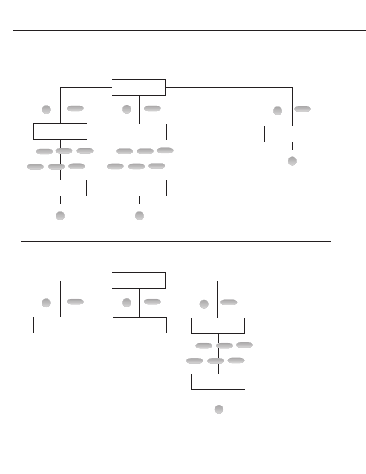
If the functionality has been set to FN4, the unit will operate as a Batch
Counter with 2 seperate control functions. Preset 2 is for the primary
count value (6 pcs. per box) while preset 1 is for the batch value (24
boxes per pallet). To enter the Program mode, hold down the Edit key
and the "5" key during power-up. Use the Edit key to move from one
parameter to the next, and the "1" key to scroll through the parameter
choices. Holding down the Edit key for 5 seconds will return the unit to
Operation mode.
During Power-up
F0
E
F1
E
F3
E
0
PRG
0
PRG
0
PRG
F0 Default Settings: Changing this value from 0 to 1 will set all parameters back to their default values. A
setting of 0 has no effect on the other parameters.
F1 Count Mode: Defines the functionality of the 3 inputs. The choices are:
Code Input A Input B Input C
0 Count Input Inhibit Reset
1 Count Input Direction (U/D) Reset
2 Count Input Direction (U/D) Inhibit
3 Incrementing Decrementing Reset
4 Incrementing Decrementing Inhibit
5 Incrementing Incrementing Reset
6 Channel A* Channel B* Reset
7 Channel A* Channel B* Inhibit
* Quadrature counting for encoders
F3 Display Decimal Point: Defines the number of digits displayed to the right of the decimal point for
both registers. Settable in a range from 0 to 3.
17
Page 18

PROGRAMMING
F4
F6
F7
F9
E
E
E
E
0
PRG
0.10
PRG
0.10
PRG
0
PRG
F4 Reset Operation: Defines how the count value will behave when the preset is reached. Choices are:
0 Reset to "0", no Autoreset
1 Reset to "0", Autoreset
2 Reset to Preset, no Autoreset
3 Reset to Preset, Autoreset
F6 Output 1 Time: Sets the amount of time Output 1 will be active once the Preset is reached. Choices are:
Off No output
On Latching output (for dual presets, output 2 will deactivate output 1 )
0.02 20 ms
0.05 50 ms
0.10 100 ms
0.50 500 ms
1.00 1 sec.
F7 Output 2 Time: Sets the amount of time Output 2 will be active after the Preset is reached. Choices
are the same as Output 1
F9 Output on Reset: When set to ON (1), the primary output (Output 2 on dual preset version) will
activate when the unit is reset.
F10
F11
F12
F14
1
PRG
E
1
PRG
E
0
PRG
E
0
PRG
E
F10 Input Type: Enables the unit to be programmed to work with either sinking or sourcing inputs.
Choices are NPN (0), and PNP (1)
F11 Count Speed: Enables the unit to be set for full speed of 5 kHz (1) or to 30 Hz (0) to provide
debounce filtering for contact inputs.
F12 Static/Dynamic Reset: When set to static reset (0) counting stops on the leading edge of the reset
input and does not resume until the trailing edge. When set to dynamic reset (1) the Count Value is
immediately reset on the leading edge of the reset signal, and will accumulate while the reset signal is
still active.
F14 Output Signal Memory: Determines if after power interruption the outputs will resume their state
prior to the loss of power (1) or if the output will be reset (0)
18
F20
0
PRG
E
F20 Front Panel Reset Enable: When active (0), the count value and output(s) can be reset by
simultaneously pressing the "6" and "4" keys. If set to Off (1), reset can only take place through the
remote input, or through the front panel by holding the "6" and "4" keys for 10 seconds (see F29).
Page 19

F21
0
PRG
E
F21 Preset 1 Enable: When active (0), the Preset 1 value can be accessed by simultaneously holding
down the Edit key and the "1' key. If set to inactive (1), Preset 1 can not be accessed, or only accessed by
holding down the Edit key and the "1" key for 10 seconds (see F29)
F22
F23
F29
0
PRG
E
0
PRG
E
0
PRG
F22 Preset 2 Access Enable: When active (0), the Preset 2 value can be accessed by simultaneously
holding down the Edit key and the "2" key. If set to inactive (1), Preset 2 can not be accessed, or only
accessed by holding down the Edit key and the "2" key for 10 seconds (see F29).
F23 Prescale Enable: When active (0), the Prescale value can be accessed by simultaneously holding
down the Edit key and the "3" key. If set to inactive (1), Prescale can not be accessed, or only accessed
by holding down the Edit key and the "3" key for 10 seconds (see F29).
F29 Lockout Mode: If parameters F21, F22 and F23 are set to inactive, Preset 1 & 2 and the Prescale
value can still be accessed by holding down the respective keys for 10 seconds if this parameter is set to
active (0). If set to inactive (1), those values can not be accessed.
SPECIFICATIONS
Count Operation:
Count Modes: Add/Subtract Add/Add, Directional input or
Quadrature
Count Speed: 30 Hz (17ms min. pulse width), or 5 kHz (100µs min.
pulse width) field selectable (2 kHz in quadrature)
Presets: 6 digit, Single (C346-0_1), Dual (C346-0_2)
Reset: Front panel (selectable enable), remote input or automatic
Calibrator: 0.001 to 9.999 multiplier common to inputs A and B
Decimal Point: Selectable from XXXX to X.XXX
Rate Meter Operation:
Mode of Operation: Time interval (1/Tau)
Update Time: 500ms for each input if frequency is >2Hz
Alarms: Upper and Lower absolute value
Calibrator: 0.001 to 9.999 multiplier common to inputs A and B
Elapsed Time Operation:
Timing Modes: Pulse Width Measurement (cumulative or singular),
Period Measurement (cumulative or singular)
Time Ranges: Selectable for Seconds, Minutes, Hours
Resolution: Selectable from XXXX to X.XXX
Physical:
Dimensions: 48mm x 48mm, 93.5mm deep
Mounting: Panel mount (mounting bracket supplied), 45mm x 45mm
cutout
Terminals: Screw Type
Display: Single line seven segment LED, 7.6mm high or Single line
LCD, 9mm high
General:
Supply Voltage: 115 VAC, 230 VAC 50/60Hz, 12 - 24 VDC
Current Consumption: DC < 150 mA, AC < 50 mA
Accessory Power: 12 to 24 VDC, 0 - 50mA
Ambient Temperature - Operating: 0 to 50˚ C, 32 to 122˚ F
Ambient Temperature - Storage: -20 to 60˚ C -4 to 140˚ F
Front Panel Rating: NEMA 4/IP65
Approvals: CE, UL, CUL
Inputs:
Count Inputs: Contact Closure, Sourcing, Sinking, low < 2.0 VDC,
high > 8.0 VDC, 40VDC Max.
Control Inputs: Remote Reset and Program Enable; low < 2.0
VDC, high > 8.0 VDC, 40VDC Max.
Input Resistance: approx. 5KΩ
Minimum Pulse Width: 17 ms (30 Hz), 100 µs (5 kHz)
Maximum Voltage: 40 VDC
Outputs:
Number: 1 relay and 1 transistor per preset
Relay(s): SPDT 1A resistive @ 250 VAC
Transistor: PNP open collector, 24 VDC max, 10 mA max
19
Page 20

GENERAL
PROGRAMMING
ORDERING INFORMATION
Description Model #
LCD/Single Preset/AC115 C346-0411
LCD/Single Preset/AC230 C346-0413
LCD/Single Preset/DC 12-24 C346-0412
LCD/Dual Preset/AC115 C346-0421
LCD/Dual Preset/AC230 C346-0423
LCD Dual Preset/DC 12-24 C346-0422
LED/Single Preset/AC115 C346-0511
LED/Single Preset/AC230 C346-0513
LED/Single Preset/DC 12-24 C346-0512
LED/Dual Preset/AC115 C346-0521
LED/Dual Preset/AC230 C346-0523
WARRANTY
LED/Dual Preset/DC 12-24 C346-0522
Standard products manufactured by the
Company are warranted to be free from defects
in workmanship and material for a period of one
year from the date of shipment, and products
which are defective in workmanship or material
will be repaired or replaced, at the option of the
Company, at no charge to the Buyer. Final
determination as to whether a product is
actually defective rests with the Company. The
obligation of the Company hereunder shall be
limited solely to repair and replacement of
products that fall within the foregoing
limitations, and shall be conditioned upon
receipt by the Company of written notice of any
alleged defects or deficiency promptly after
discovery within the warranty period, and in the
case of components or units purchased by the
Company, the obligation of the Company shall
not exceed the settlement that the Company is
able to obtain from the supplier thereof. No
products shall be returned to the Company
without its prior consent. Products which the
Company consents to have returned shall be
shipped F.O.B. the Company's factory. The
Company cannot assume responsibility or accept
invoices for unauthorized repairs to its
components, even though defective. The life of
the products of the Company depends, to a large
extent, upon the type of usage thereof, and THE
COMPANY MAKES NO WARRANTY AS TO
FITNESS OF ITS PRODUCTS FOR SPECIFIC
APPLICATIONS BY THE BUYER NOR AS TO
PERIOD OF SERVICE UNLESS THE COMPANY
SPECIFICALLY AGREES OTHERWISE IN
WRITING AFTER THE PROPOSED USAGE HAS
BEEN MADE KNOWN TO IT.
THE FOREGOING WARRANTY IS EXCLUSIVE
AND IN LIEU OF ALL OTHER WARRANTIES
EXPRESSED OR IMPLIED, INCLUDING, BUT
NOT LIMITED TO ANY WARRANTY OF
MERCHANTABILITY OR OF FITNESS FOR A
PARTICULAR PURPOSE.
20
Printed in U.S.A.
#701996-0000
January 1996
Revision: A
Danaher Controls
1675 Delany Road
Gurnee, IL 60031–1282
Phone: 847.662.2666
Fax: 847.662.6633
 Loading...