

Page 1
Introduction
Veeder-Root
brand
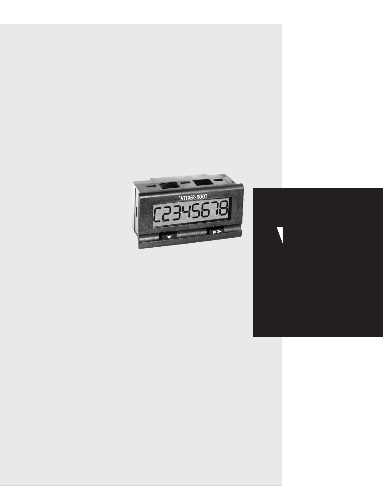
Within the Danaher Controls A103 family you'll find a product to meet nearly every
requirement for panel mounted control and indication. Housed in a DIN standard 36mm x
72mm case, the A103-007 is an ideal choice for event counting operations which require a
preset. An intenal solid state relay provides a logic signal that can be sent to antother
control device or to an external relay.
The 8 digit supertwist LCD display provides easy viewing at a glance. For conditions where
ambient light is poor, the display can be backlit by connecting an external DC (10-28 Volt)
power supply. A single unit can accept NPN & dry contact inputs for low speed (30Hz)
counting and PNP or square wave signals for high speed applications up to 10 kHz.
Powered by either one or two replaceable 3V Lithium batteries, this unique design allows for
a new battery to be installed before removing the old one, thereby retaining count total and
program data. A low battery indicator appears on the screen to provide a warning several
weeks before the end of battery life. If two batteries are used simultaneously, the individual
expected life doubles to 10 years.
Setup is quick and simple as the two
front panel keys are used to scroll
through 4 menu choices. A NEMA 4X
front panel and noise immunity tested
to IEC 801 level 3 makes this unit
suitable for harsh environments.
Several option modules are available,
inclunding a 5 amp relay which would
enalbe the unit to directly drive a
load.
Technical Manual
701954-0008
Features
•
Large, easy to read 8-digit supertwist LCD
with backlighting capability
•
Display can be toggled between count and
preset value
•
Powered by an internal 3 Volt lithium
battery
•
Accepts low speed (30 Hz) NPN & dry
contact inputs, and high speed (10 kHz)
PNP signals or square wave signals
•
0.1 Amp SSR output
•
Option Modules provide added
functionality and convenience
•
Simple menu-driven setup
•
NEMA 4X rated front panel for use in
washdown environments
Index
Overview
Operation page 2
Terminal Connections page 2
Setup
Installation page 3
Programming page 3
General
Specifications page 4
Warranty page 4
A103-007
Preset
Counter
1
Page 2
OVERVIEW
OPERATION
VEEDER-ROOT
C.2345678
R
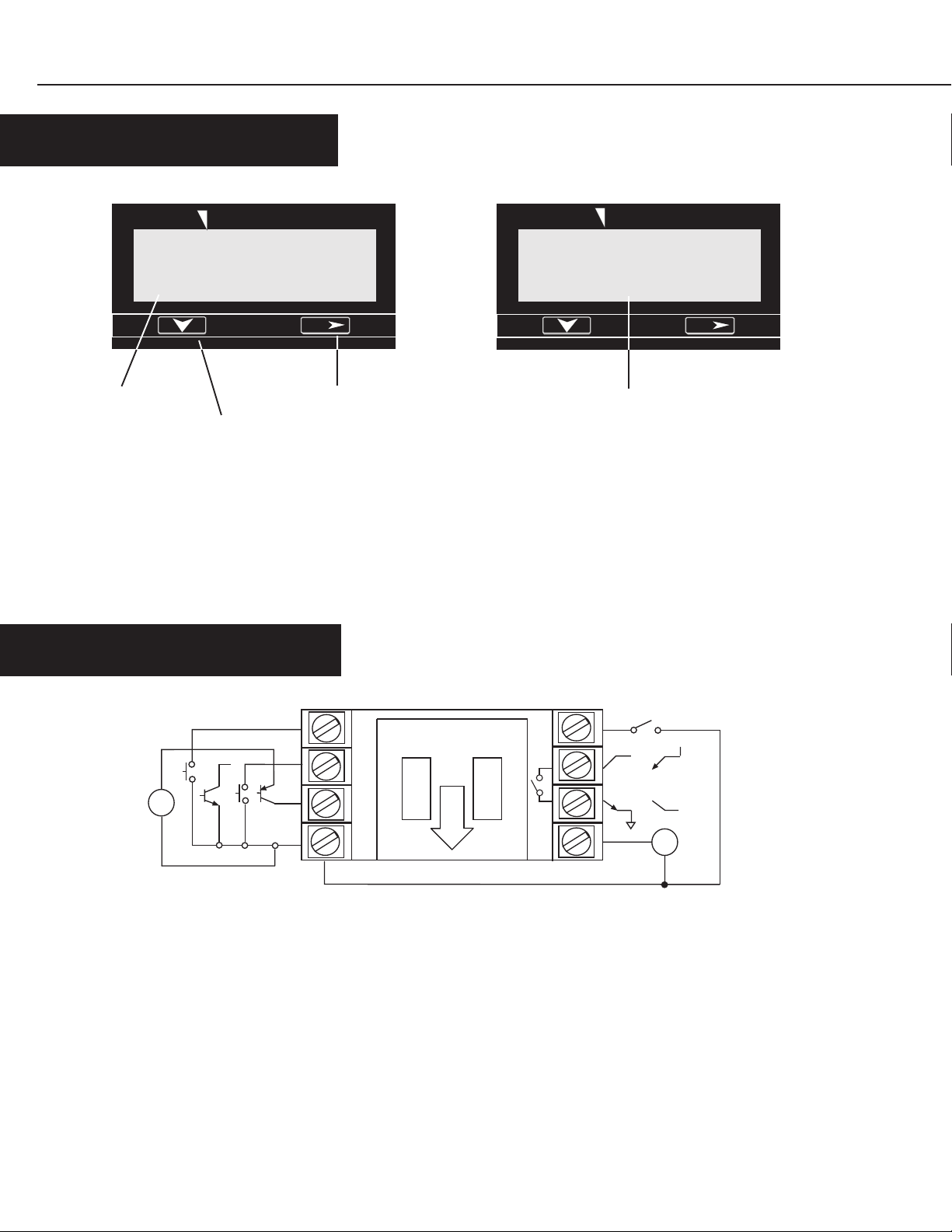
1. Total Display
2. Down Key
1. Total Display: Indicates the present count value, which is equal to
the number of pulses received since the last reset
2. Down Key: Toggles the unit between the total and preset displays
when in Operation Mode. When the program input is active this key is
used to scroll through the menu items. After a menu item has been
chosen for editing, the down key is used to set the value for the
currently selected (flashing) digit.
REAR TERMINAL CONNECTIONS
3. Next/Reset Key
3. Next/Reset Key: When in Operation Mode, depressing the key will
reset the count value to 0, if Front Panel Reset has been enabled in
Programming Mode. When the program input is active this key is used
to select a menu item for editing (left most digit will begin to flash) and
then move to the desired digit to be changed.
4. Preset Value: Indicates the number at which the output will be
activated (for Up counting) or the reset value (for Down counting)
P.3456789
4. Preset Value
VEEDER-ROOT
R
+
-
1. Common
2. High Speed Input A - PNP or squre
signals up to 10 kHz* for incrementing the
count value
3. Low Speed Input A - NPN or dry contact
inputs up to 30 Hz for incrementing the
count value
4. Remote Reset - Resets count value when
switched to common
2
4
3
2
1
5
+
6
Sink Source
7
8
10 - 28 VDC
5. Front Panel Program Enable - Allows access to
program mode when switched to common
6. & 7. - Form A SSR Output
8. DC Supply Input - For backlighting
* For high speed current sinking devices, provide a pull-up
resistor from terminal 2 to a DC source
+
-
Page 3

SETUP
INSTALLATION
36mm
+ BATT -
BATT +
-
Battery Slots
Battery Installation - The unit is shipped with two battery, which are not
installed. Remove the battery cover by pushing inward and down. Install
the batteries in the two slots. The two batteries are capable of sustaining
the output for 6 months at 50% duty cycle (To extend the battery life to 5
years utilize an external DC supply or the AC option module for powering
the output). Once the battery is in place the unit will go into a self test
mode, and all the segments on the LCD display will be illuminated. The self
test mode is exited by depressing the Next key, which will then display the
model number (7). Depress the Next key again to ready the unit for
operation.
Front Panel Installation - Place the unit in the panel through the
33mm x 68mm cutout. Slide the included gasket over the rear of the
unit, then slide the panel mount bracket into place so that the 4 tabs
catch in the groves on the top and the bottom of the unit (the bracket
should be oriented so that the tabs are on the side nearest the panel).
Use the provided panel mount screws to tighten the bracket until there
is a secure seal against the gasket.
33mm
72mm
68mm
4
3
2
1
8
7
6
5
PROGRAMMING
1. uP
2.
3.
4.
5.
oFF
int
on
on
Programming parameters can be accessed, when the Program Enable input is active, by
pressing the Down key. To edit a parameter use the Down key to scroll until the
desired parameter appears on the screen. Pressing the Next key will cause the leftmost
digit of that value to begin to flash. Use the Next and Down keys in combination to
choose individual digits and change their value.
Count Direction: Determines if the count value will increment from zero and change the state of the
output at the preset (Up), or decrement from the Preset and change the state of the output at zero
(Down).
Preset Lock: When enabled the preset value can not be changed through the front panel.
Output Mode - Determines whether the output will activate prior to reaching the preset (or zero for
down counting) and then release when that value is achieved (Interval), or will be Off prior to reaching
the preset (or zero for down counting) and then activate when that value is achieved (On-Delay).
Front Panel Reset Enable: When active (ON) the count value, when being displayed, can be reset by
pressing the Next/Reset key. If set to OFF, the total value can only be reset through the remote input.
Output Enable: When active (on), the SSR output will activate as described above in Output Mode.
If set to off, the output will not activate. (Use the "off" setting to conserve battery life if not using the output)
3
Page 4

SPECIFICATIONS
GENERAL
High Speed Input (Terminal 2)
Type: PNP Signal or square wave pulse
Count Speed: 10 kHz max (50% duty cycle),
Logic: Low < 1.0 VDC, High > 2.0 VDC
Minimum Pulse Width: 45 µsecond
Maximum Input: 28VDC
Impedence: 15 KΩ to common
Low Speed Input (Terminal 3)
Type: NPN Signal, Contact Closure
Count Speed: 30 Hz max (50% duty cycle)
Logic: Low < 1.0 VDC, High > 2.0 VDC
Minimum Pulse Width: 12 ms
Maximum Input 28VDC
Impedence: 1 MΩ to battery
Front Panel Enable Input (Terminal 5)
Type: NPN Signal, Contact Closure; level sensitive
Maximum Input: 28 VDC
Remote Reset Input (Terminal 4)
Type: NPN Signal, Contact Closure; edge sensitive
Frequency Response: 30 Hz (50% duty cycle)
Maximum input: 28 VDC
WARRANTY
Output (Terminals 6 & 7)
Type: Isolated Photomos Relay
Load Rating: 0.1 Amp @ 30 VAC/VDC
Transistion Time: < 5ms
Power Source:
Type: Single or dual 3V Lithium battery
Expected Life: 5 years typical-single battery if using AC power
supply option module or external DC supply.
6 months if used alone with 50% duty cycle output. No
reduction in battery life if output is programmed to "off"
Low Power Indicator: "Low Bat" flashes on display
approx. 2 weeks prior to end of battery life
Display:
Type: Supertwist LCD for use with or without backlighting
Number: 8 digits
Height: 12mm
Backlighting: Green Illumination over whole
viewable area with a 10 to 28 VDC supply (Terminal 8)
Physical:
Dimensions: 36mm x 72mm, 38mm deep
Mounting: Panel Mount (mounting bracket supplied)
33mm x 68mm (+ 0.3mm) panel cutout
Connections: Up to 8 screw terminals
Weight: Approximately 2.25 ounces
Standard products manufactured by the
Company are warranted to be free from defects
in workmanship and material for a period of one
year from the date of shipment, and products
which are defective in workmanship or material
will be repaired or replaced, at the option of the
Company, at no charge to the Buyer. Final
determination as to whether a product is
actually defective rests with the Company. The
obligation of the Company hereunder shall be
limited solely to repair and replacement of
products that fall within the foregoing
limitations, and shall be conditioned upon
receipt by the Company of written notice of any
alleged defects or deficiency promptly after
discovery within the warranty period, and in the
case of components or units purchased by the
Company, the obligation of the Company shall
not exceed the settlement that the Company is
able to obtain from the supplier thereof. No
products shall be returned to the Company
without its prior consent. Products which the
Company consents to have returned shall be
shipped F.O.B. the Company's factory. The
Company cannot assume responsibility or accept
invoices for unauthorized repairs to its
components, even though defective. The life of
the products of the Company depends, to a large
extent, upon the type of usage thereof, and THE
COMPANY MAKES NO WARRANTY AS TO
FITNESS OF ITS PRODUCTS FOR SPECIFIC
APPLICATIONS BY THE BUYER NOR AS TO
PERIOD OF SERVICE UNLESS THE COMPANY
SPECIFICALLY AGREES OTHERWISE IN
WRITING AFTER THE PROPOSED USAGE HAS
BEEN MADE KNOWN TO IT.
THE FOREGOING WARRANTY IS EXCLUSIVE
AND IN LIEU OF ALL OTHER WARRANTIES
EXPRESSED OR IMPLIED, INCLUDING, BUT
NOT LIMITED TO ANY WARRANTY OF
MERCHANTABILITY OR OF FITNESS FOR A
PARTICULAR PURPOSE.
Danaher Controls
Printed in U.S.A.
#701954-0008
Revision B
4
4/14/04
1675 N. Delany Road
Gurnee, IL 60031–1282
Phone: 847.662.2666
Fax: 847.662.6633
 Loading...