

Veeco MS40 Operation And Maintenance Manual

n
Table Of Contents
Section 1: General Information
1.1 Introduction 1-1
1.2 Unpacking & Inspection 1-3
1.3 Installation 1-7
1.4 Features & Specifications 1-8
1.5 General Description 1-11
Section 2: Operating the MS-40
2.1 Introduction 2-1
2.2 Operator Controls & Indicators 2-3
2.3 Starting the MS-40 Leak Detector 2-19
2.4 Leak Testing 2-20
2.5 Operation With an External Pump 2-22
2.6 Shut Down Procedure 2-25
2.7 Setting Test Parameters 2-25
2.8 Setting Additional Parameters 2-31
2.9 Test Aids & Procedures 2-32
Section 3: Theory of Operation
3.1 Introduction 3-1
3.2 Direct Flow & Reverse Flow Modes. 3-4
3.3 Functional Description of Operation 3-6
3.4 Description of Major Components 3-11
Section 4: Service & Maintenance
4.1 Introduction 4-1
4.2 Service Mode 4-1
4.3
4.4 Periodic Service 4-4
Calibration & Tuning 4-2
VIC Leak Detectio
2099 Ninth Avenue
Ronkonkoma, NY 11779
631.737.0900
1109-186-00 Rev. C toc-i

VIC Leak Detectio
n
n
VIC Leak Detectio
2099 Ninth Avenue
2099 Ninth Avenue
Ronkonkoma, NY 11779
Ronkonkoma, NY 11779
631.737.0900
631.737.0900
4.5 Contamination of the Vacuum System 4-8
4.6 Venting the Vacuum System 4-11
4.7 Cleaning Requirements 4-12
4.8 Calibration Requirements 4-19
4.9 General Service & Repair 4-21
4.10 Troubleshooting Aids 4-32
Section 5: Parts List
5.1 Introduction 5-1
5.2 Recommended Spare Parts for the MS-40 5-2
5.3 Other Components 5-5
Appendix A:
Glossary of Terms Used in Leak Detection
Appendix B:
A.V.S. Standards for Testing of Mass Spectrometer Leak Detectors
Appendix C:
Leakage Conversion Factors
Appendix D:
Remote Port Specifications
Appendix E:
Profile and Revision Switch Positions
Appendix F:
MS-40 Quick Reference
1109-186-00 Rev. A toc-ii

General Information
1.1 Introduction
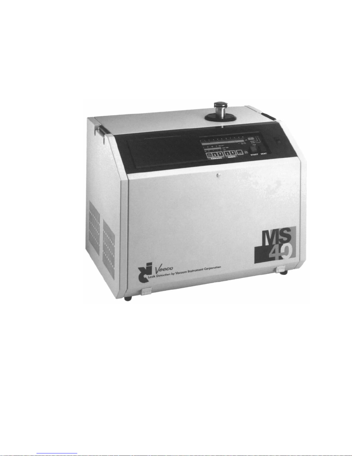
This Operations & Maintenance Manual describes in detail the
information needed to understand the operation and functions of the
VIC MS-40 Fully Automatic Portable Leak Detector (illustrated in
Figure 1-1), and provides the information needed to service and maintain
the unit in optimal working condition. This manual has been divided into
five chapters:
• Chapter 1 General Information
• Chapter 2 Operating the MS-40
• Chapter 3 Theory of Operation
• Chapter 4 Service & Maintenance
• Chapter 5 Parts Lists
Chapter 1, General Information, describes the features of the MS-40 Leak
Detector, its basic operation, unpacking and inspection of the unit, installation
requirements as well as specifications for the unit.
Chapter 2, Operating the MS-40, details the controls necessary to operate
the MS-40, both during normal operation of the unit as well as when
placed in Service Mode. All external connectors and their
applicability to the unit and its functions are also discussed. This chapter
also includes an explanation of what occurs during the unit’s start-up
procedure, a description of the leak test modes, an explanation of sniff
testing procedures, a step-by-step description of how to perform actual
leak testing, operations involving the optional external pump, an
explanation of what occurs during the unit’s shutdown procedure, the
setting of the unit’s testing parameters, and MS-40 self-testing procedures.
Chapter 3, Theory of Operation, has been included in order to give the
MS-40 user information on how the unit functions. Maintenance
personnel servicing the unit will find this most useful, since a thorough
technical understanding of how the unit operates is critical when
performing the repairs and service discussed in the following chapter.
Vacuum Instrument Corp.
2099 Ninth Avenue
Ronkonkoma, NY 11779
631.737.0900
1109-186-00 Rev. C 1-1
VIC Model MS-40 Portable Automatic Leak Detector
1109-186-00 Rev. C 1-2
Figure 1-1

Vacuum Instrument Corp.
2099 Ninth Avenue
Ronkonkoma, NY 11779
631.737.0900
Chapter 4, Service & Maintenance, describes in further detail the unit’s
Service Mode, the necessary tuning/calibration procedures for the MS-40,
required periodic service procedures and recommended service intervals,
detection and correction of contamination within the vacuum system,
procedures for venting the vacuum system, cleaning requirements and
procedures, calibration of measurement components, valve block service and
repair, repair/replacement of the unit’s electronics and a full listing of front
panel error codes, their probable causes and our recommended corrective
actions.
Chapter 5, MS-40 Parts Lists, contains a full list of recommended spare parts
and a complete listing of the spare parts available from VIC.
This manual provides the specific documentation needed to operate and
service the MS-40 Leak Detector. The MS-40 System is a highly technical
system that incorporates many sophisticated technologies. In view of this,
every effort has been made to automate both the unit’s operation and
maintenance procedures. It is imperative, however, that operations and service
personnel familiarize themselves with the operations and maintenance
procedures in this manual in order to maximize the efficiency of the unit, as
well as minimize downtime caused by improper service and repair.
1.2 Unpacking & Inspection
The MS-40 is shipped in a specially constructed package that minimizes the
possibility of damage during transit. The shipping carton and packing
materials should be saved for future use. Note that a Bill of Material is packed
within the carton indicating all of the items shipped with the unit.
Prior to unpacking the unit, inspect the exterior carton for any signs of
damage. After unpacking the unit, inspect the leak detector itself for any
obvious damage. If damage to the unit is found, a claim should be filed
immediately with the shipping carrier and a copy of that claim must also be
forwarded to Vacuum Instrument. Should the MS-40 fail to function as
required, or fail to meet its specifications, contact the Customer Service
Department at VIC (Vacuum Instrument, 2099 Ninth Avenue Ronkonkoma,
NY 11779, 631-737-0900) or your local representative. Please note that
Vacuum Instrument must be contacted prior to the return of any damaged
equipment.
Once the leak detector has been removed from its package, the MS-40 must
be opened and all shipping material removed from the unit’s internal
roughing and turbo-molecular pumps. To access the internal roughing
pump, the front panel must be opened to access the turbo-molecular pump,
1109-186-00 Rev. C 1-3

the back panel must be opened. Both panels are hinged at the bottom and
held with a single screw at the top of each panel. To open a panel, loosen
the captive screw at the top of the panel (a 1/4 turn is sufficient to unloosen
the screw) and gently lower the door. Make sure that the surface the unit is
placed on a flat surface (VIC Cart, P/N 0137-705-00, recommended).
Remove all shipping materials and tie-down wraps from the internal
pumps.
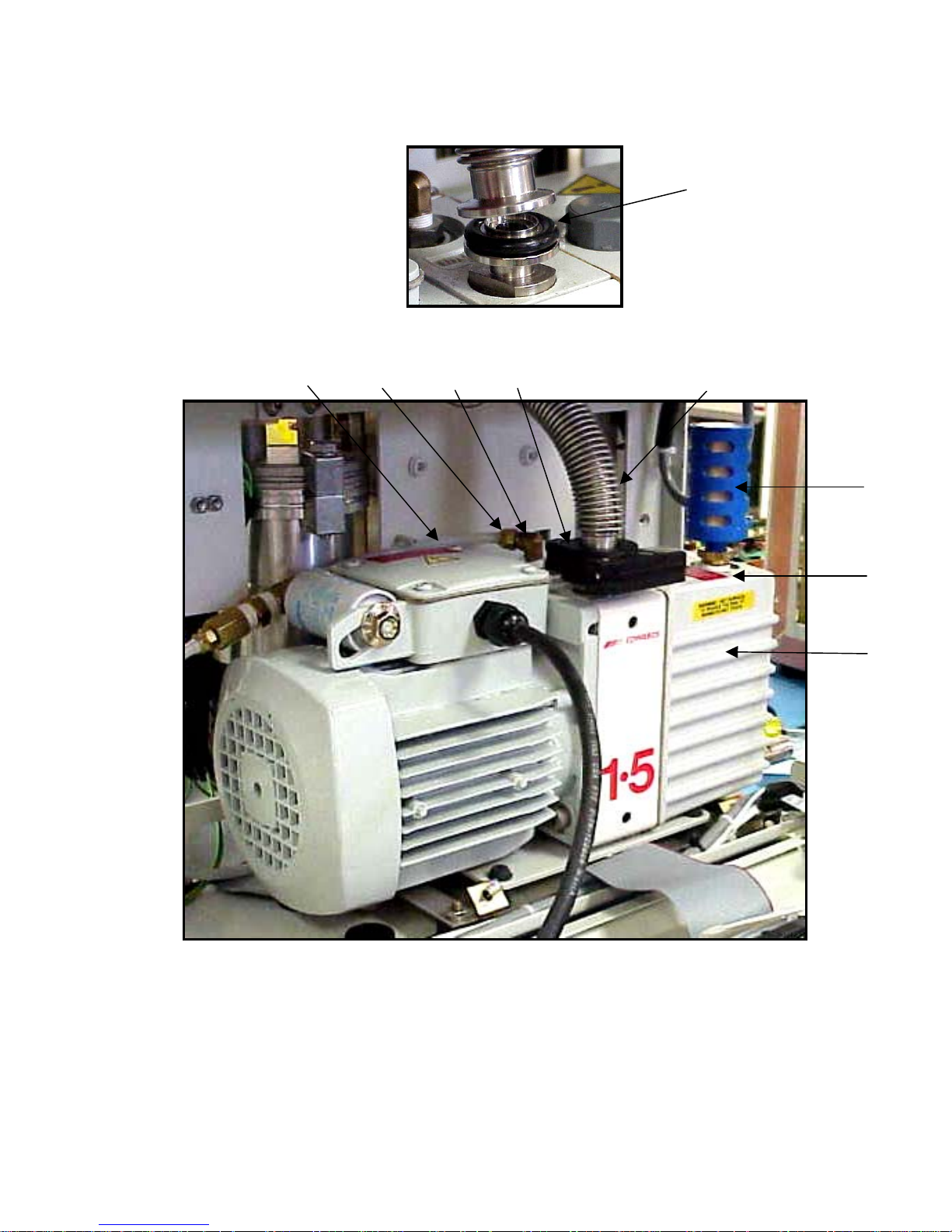
The MS-40 is shipped without oil in the internal roughing pump, which must
be filled prior to use. In addition, to protect the pump during shipment, it is
fitted with two blanks that cover its intake and filter connections. Remove
these blanks and attach the flex hosing and filter (refer to Figure 1-2 for a
diagram illustrating the proper installation for the hose and filter connections)
with the provided centering rings and clamps. Also, the unit’s purge tubing
(refer to Figure 1-2) is fitted with a 1/4” ferrule blank. Unscrew the blank and
reattach the tubing as indicated in Figure 1-2.
Parts List for Figure 1-2:
ILLUSTRATION # PART NUMBER DESCRIPTION
1 1660-362-00 110/120v (60Hz)
1660-362-01 220/240v (50 Hz) Pump
2 1621-183-00 Ferrule Nut
3 1750-046-00 Poly-flo Tubing, Purge Line
4 1620-726-00 Elbow / with ferrule nut
5 1621-231-12 KF16 Centering Ring
6 1621-239-02 KF16 Clamp
7 0137-205-00 Manifold, Roughing Pump
8 1680-055-00 Exhaust Filter
KF16 to 1/4 NPT Adapter
9 1620-743-00 3/8 MPT x ¼ Bushing
Vacuum Instrument Corp.
2099 Ninth Avenue
Ronkonkoma, NY 11779
631.737.0900
1109-186-00 Rev. C 1-4

n
To fill the pump with oil, unscrew the black cap to the right of the exhaust
filter. Using the oil (1990-924-00) and the funnel (1331-191-00) provided
in the installation kit, slowly fill the pump until the level in the sight glass
is approximately 1/4” below the fill line. Replace the black oil fill cap.
When all shipping material has been removed, all pump connections have
been made and the pump has been filled with oil, replace the right side
panel and close the front and rear doors.
NOTE:
The MS-40 Leak Detector is factory tested and calibrated
prior to shipment and once installed, is ready for use.
An Installation Kit (VIC P/N 0137-800-00) is included with the unit when it
is shipped. The kit contains:
Part Number Description
1680-055-00 Exhaust Filter
0103-141-01 Filament Kit (box of 5)
1331-191-00 Funnel
1330-391-00 7/64 Allen Wrench
1990-924-00 VMP-19 Oil (1 liter)
0137-807-00 Kit, Cart Mounting
0137-804-00 N2 Kit
1621-224-02 Adapter, KF16 to 1/4” NPT
1621-227-05 QC Adapter, KF25 to 1 1/8”
0126-284-00 Blank Plug, 1/18
1620-731-00 Elbow, 1/4 NPT to 3/8 Tube
1750-054-00 Tubing, Tygon, 1/4”
VIC Leak Detectio
2099 Ninth Avenue
Ronkonkoma, NY 11779
631.737.0900
1109-186-00 Rev. C 1-5
5
3
2
4
7
8
9
1
INTERNAL ROTARY VANE MECHANICAL PUMP
FIGURE 1 - 2
1109-186-00 Rev. C 1-6

VIC Leak Detectio
n
2099 Ninth Avenue
Ronkonkoma, NY 11779
631.737.0900
1.3 Installation
The MS-40 has been designed as a completely self-contained portable leak
detector and therefore has the capability to work in a wide range of
environments. However, before installation in a work area, certain
requirements must be met.
• A properly grounded electrical supply (115V/60Hz/10A,
230-240V/50Hz/5A, 100V/50Hz/10A, or 100V/60Hz/10A as
labeled on rear of unit) must be available for the unit.
• A user supplied helium supply is usually necessary for the unit
(but not for all testing, e.g., sealed parts should already be pre bombed with helium). The MS-40 can use either a Mass 3 or
Mass 4 helium supply. Virtually any standard purity helium
may be used during leak testing. Depending on the type of leak
testing that will be performed, a spray probe (for vacuum
testing), a sniffer assembly (for sniff testing) or a test cup (for
pressure bombing testing) will be necessary. All of these items
are available directly from Vacuum Instrument.
• The recommended ambient temperature range for the unit is
from 10°C to 40°C. Also, excessively humid environments
should be avoided.
• Depending upon the immediate environment, an external
exhaust facility may be necessary. A bulkhead is installed on
the rear of the MS-40 that is intended for user-provided 3/8”
polyflow tubing. Note that the bulkhead is not connected to the
internal exhaust filter of the unit but must be connected by the
User. The tubing is then attached to a functional exhaust system.
WARNING!
Only qualified service personnel should operate the unit when either
the front or rear panels are open. Potentially lethal high voltages are
continually applied to the circuit boards and other areas within the
unit during its operation. Although these areas are shielded and well
marked, failure to follow this precaution may possibly lead to severe
injury or death.
1109-186-00 Rev. C 1-7

Vacuum Instrument Corp.
2099 Ninth Avenue
Ronkonkoma, NY 11779
631.737.0900
1.4 Features & Specifications
FEATURES
Sensitivity: 4 x 10
-11
std cc/sec air equivalent
Leak Rate Range: 10 to 4 x 10
-11
std cc/sec air equivalent
(with optional external pump)
10 x 10
-4
to 4 x 10
-11
std cc/sec air equivalent
(without external pump)
Start-Up: Fully functional in less than 3 minutes. Consists of:
Turbo-molecular pump acceleration, a complete set
of self-diagnostics, turning on filament, checking
and assuring Hi-Vac status, measuring system
offsets and measuring background helium
Internal Calibrator: Helium 4, 1 x 10
-8
to 3 x 10⁻⁸ std cc/sec air
equivalent with integral solenoid valve
Testable Masses: Helium Mass 3 or 4
Tuning: Automatic
Calibration: Automatic for Helium 4 using an internal calibrator
of 1 x 10
-8
to 3 x 10⁻⁸ std cc/sec air equivalent
Auto Zero: Automatic zeroing of leak rate while in test mode
initiated by pressing the ZERO pushbutton
Background Continuous automatic compensation for system back
Compensation: ground
Remote Control Molded A.B.S. plastic laminate over tactile
Unit: membrane switch array Controls similar to User
Panel
RS-232C Port: Two standard bi-directional ports. One port
dedicated to the remote control unit. The second
port is dedicated to data transfer to an external
computer or control module.
1109-186-00 Rev. C 1-8

Vacuum Instrument Corp.
Vacuum Instrument Corp.
2099 Ninth Avenue
2099 Ninth Avenue
Ronkonkoma, NY 11779
Ronkonkoma, NY 11779
631.737.0900
631.737.0900
Ranging: Without an external roughing pump, begins at the
[Automatic/Standard least sensitive gross range (10
-4
). The unit ranges
Mode] downward until a leak is detected or until it reaches
its most sensitive range (10
-10
). With the optional
external pump, if a gross leak is detected, the unit
ranges up to the appropriate decade. If a gross leak
is not detected the unit ranges downward until a leak
is detected or until it reaches its most sensitive
range.
Ranging: May operate at any range, selectable by the operator.
[Manual Mode] The 10
0
to 10-3 range is only available when the
optional external pump has been installed.
Measurement Units: Pressure: millitorr or millibar (selectable with a
switch located underneath the Service Panel accessible
when the unit’s front panel has been opened)
Leak Rate: std cc/sec (standard cubic centimeters/
second) or mbar l/sec (millibar liters/second)
PUMPS
Mechanical Pump: Internal 1.5 CFM dual stage rotary vane pump
Turbo Pump: 60 liter/second turbo-molecular pump
External Pump: Optional 7 or 16 CFM dual stage rotary vane
(Mechanical pump)
PERFORMANCE SPECIFICATIONS
Sensitivity: 4 x 10
4 x 10
-11
Std cc/sec air equivalent (direct mode)
-10
Std cc/sec air equivalent (reverse mode)
Resolution: 14 at Mass 4
Response Time: Reverse Mode < 3 seconds
Fine Mode < 2 seconds
Test Time: <2.5 seconds on a blank port to a pre-selected range
in the reverse flow test mode
1109-186-00 Rev. C 1-9

Vacuum Instrument Corp.
2099 Ninth Avenue
Ronkonkoma, NY 11779
631.737.0900
Noise & Drift: <4% on 10
-10
range
Testable Masses: 3 and 4
Maximum 10 x 10
-4
std cc/sec air equivalent (without external
Measurable Leak: pump) 10 std cc/sec air equivalent (with optional
external pump)
Maximum Inlet Gross Mode: Atm (with optional external pump)
Pressure: Reverse Mode: 7.5 Torr
Direct Mode: 100 mTorr
Test Mode Leak Gross: 10 to 1 x 10
Reverse: 10 x 10
Direct: 10 x 10
-3
std cc/sec helium
-4
to 6 x 10
-5
to 6 x 10
-11
-10
ELECTRONICS & USER INTERFACE
System Controller: Microprocessor based; four integrated boards used:
A controls the unit’s computer, logic and sensors
B
controls the unit’s mass spectrometer voltage supplies
C controls the unit’s displays and controls
D controls the unit’s handheld remote
Display: Green LED alphanumeric and bar graph
displays
Data Input: Through dedicated function keys
MISCELLANEOUS
Power Requirements: 115V, 60Hz, 10 Amp
230-240V, 50Hz, 5 Amp
100V, 50Hz, 10 Amp
100V, 60Hz, 10 Amp
Dimensions: 15.5”H x 20.5”W x 14.25”D
Weight: 84.5 lbs.
1109-186-00 Rev. C 1-10

Vacuum Instrument Corp.
2099 Ninth Avenue
Ronkonkoma, NY 11779
631.737.0900
1.5 General Description
The MS-40 is a fully automatic, dual mode, turbo-molecular pumped
portable leak detector. Each of its two modes (Reverse Flow or Direct
Flow) is automatically selected by the leak detector based on the currently
selected leak rate range.
Reverse Flow Mode permits rapid testing for leaks in test objects that are
characterized by a high degree of out-gassing. Testing can start at test port
pressures of Atm for leaks from 10 to 1 x 10
-3
std cc/sec (Gross Mode
testing) when using the optional external pump or pressures of 7.5 Torr
for leaks between 10 x 10
-4
and 6 x 10
-10
std cc/sec (Intermediate Mode
testing) for units not equipped with an external pump.
Direct Flow Mode is most useful for testing objects that demand clean
testing and higher sensitivity. In this mode, the leak detector measures
leaks from 10 x 10
-9
to 6 x 10
-11
std cc/sec, at a test port pressure of 100
millitorr or less. However, this mode is also capable of determining
larger leaks. Once the unit is in this mode and a larger leak has been
detected, the unit will range back to the appropriate decade.
The MS-40 uses two types of automatic testing: an automatic test mode
with automatic ranging and an automatic test mode with manual ranging.
In automatic ranging mode, the leak detector automatically ranges
downward (to more sensitive leak rate ranges) until a leak is found. When
using manual ranging, the operator of the leak detector controls the range
in which a particular test object is tested.
In the Automatic Test Mode, when using Automatic Ranging, all the
functions of the leak detector, including the evacuation (pump down) of
the test object and the functions of all pumps and valves are controlled by
the MS-40 computer. Additionally, all measurements and display
information about the leak rate and system performance are under the
control of the computer.
The Automatic Test Mode, when using Manual Ranging, is identical to
the Automatic Testing/Automatic Ranging mode except that the User
pre-selects the range (e.g., 10
-5
std cc/sec) for testing. If a measured leak is
either above or below the pre-selected decade, the leak detector operator
can manually range the unit either up or down. The remainder of the
testing procedure is handled by the MS-40 computer in exactly the same
manner as with the Automatic Ranging Mode.
1109-186-00 Rev. C 1-11

Vacuum Instrument Corp.
2099 Ninth Avenue
Ronkonkoma, NY 11779
631.737.0900
1.5.1 Standard Operation
This is the normal operating mode for the MS-40. During operation, the User
need only use the right (uncovered) portion of the display panel (the User
Panel is illustrated in Figure 2-1). All functions to be accessed and display
information needed to leak test an object are found on this panel. The panel
displays bar graphs indicating test port pressure and leak rate values.
Additionally, the panel indicates the current leak range mode, an accept/reject
indicator that indicates if the leak being tested is above or below the test set
point, and whether the unit is in test or standby mode. The user panel also has
toggles for automatic or manual ranging (including greater/lesser
pushbuttons), audio volume pushbuttons, an auto- zero pushbutton, a sniff
mode indicator and START and VENT pushbuttons (START is used to
commence the testing cycle as well as to interrupt the testing cycle without the
chance of accidentally venting the system, while VENT is used to interrupt
testing and/or to vent the test port).
1.5.2 Service Mode
WARNING!
The Service Mode of the MS-40 is intended for use by
qualified Vacuum Instrument personnel or Users specifically
trained by Vacuum Instrument. Under no circumstances
should any individual be assigned access to this mode
without a complete knowledge of vacuum systems as well as
the MS-40 System. Use by an unqualified operator may
result in damage to the unit and/or personal injury.
Service Mode is initiated by first opening the rear panel of the unit (loosen the
1/4-turn screw at the top of the panel, then gently lower the door), and then
pressing the black toggle button at the top right hand side of the circuit board
that is attached to the panel. Once the toggle has been pressed, the unit is
placed in Service Mode and the Service Mode indicator is illuminated.
Service Mode disables the automatic valve controls and allows the User to
manually control all of the valves within the vacuum system. The valves are
controlled by a cluster of labeled momentary switches located on the left of
the User Panel. The LED indicator on each switch is lit when the valve is
open. Included within the vacuum system are: the auto-calibrator valve,
external rough valve, fine (direct) valve, fore-line (reverse) valve, gross testing
valve, purge valve, roughing valve, sniffer valve and the vent valve.
1109-186-00 Rev. C 1-12

Grouped to the right of the Service Mode Indicator are a series of LED
indicators. The Service Mode allows the setting of the unit’s Amplifier
Gain, Anode Voltage, Calibration Temperature and Internal Calibration
Value in conjunction with the arrow buttons and LED alphanumeric
display to the right of the indicators. Additionally, the user may view the
unit’s calibration temperature, the emission current of the filament within
the unit’s spectrometer, the error code present (indicating a possible fault
within the unit), the current supplied to the filament in the
mass spectrometer, the calibration standard (e.g., 2 x 10
-8
std cc/sec @
24°C) of the internal calibrator, the leak rate of the test object (a numeric
value - the same leak rate as displayed by the bar graph on the User
Panel), the pressure measured at the test port and the total number of
hours the unit has been in operation.
Below the indicators and to the right of the valve controls are two sets of
momentary switches. In either Standard or Service Modes, they allow the
User to turn on/off the filament within the mass spectrometer, choose
between two different filaments within the spectrometer, and perform an
actual test on the calibrator or optimize the mass spectrometer. When
strictly in Service Mode, the User is also able to choose between either a
helium or air standard for leak rate measurement or choose whether the
MS-40 will measure either with Mass 3 or 4 helium.
Vacuum Instrument Corp.
2099 Ninth Avenue
Ronkonkoma, NY 11779
631.737.0900
1109-186-00 Rev. C 1-13


Operating The MS-40
2.1 Introduction
This chapter contains the information needed by the user to operate the
MS-40 Leak Detector and perform leak checks on a test object. This
chapter is grouped into three general sections:
1 Operator Controls & Indicators
2 Starting & Operating the Leak Detector
3 Testing Aids & Procedures
While this chapter contains sufficient information to operate the MS-40
leak detector, we suggest that you read Chapter 3, Theory of
Operation, prior to any actual testing. An overall understanding of
the various phases of a test cycle will help the operator use the leak
detector more effectively and efficiently.
Vacuum Instrument Corp.
2099 Ninth Avenue
Ronkonkoma, NY 11779
631.737.0900
1109-186-00 Rev. C 2-1
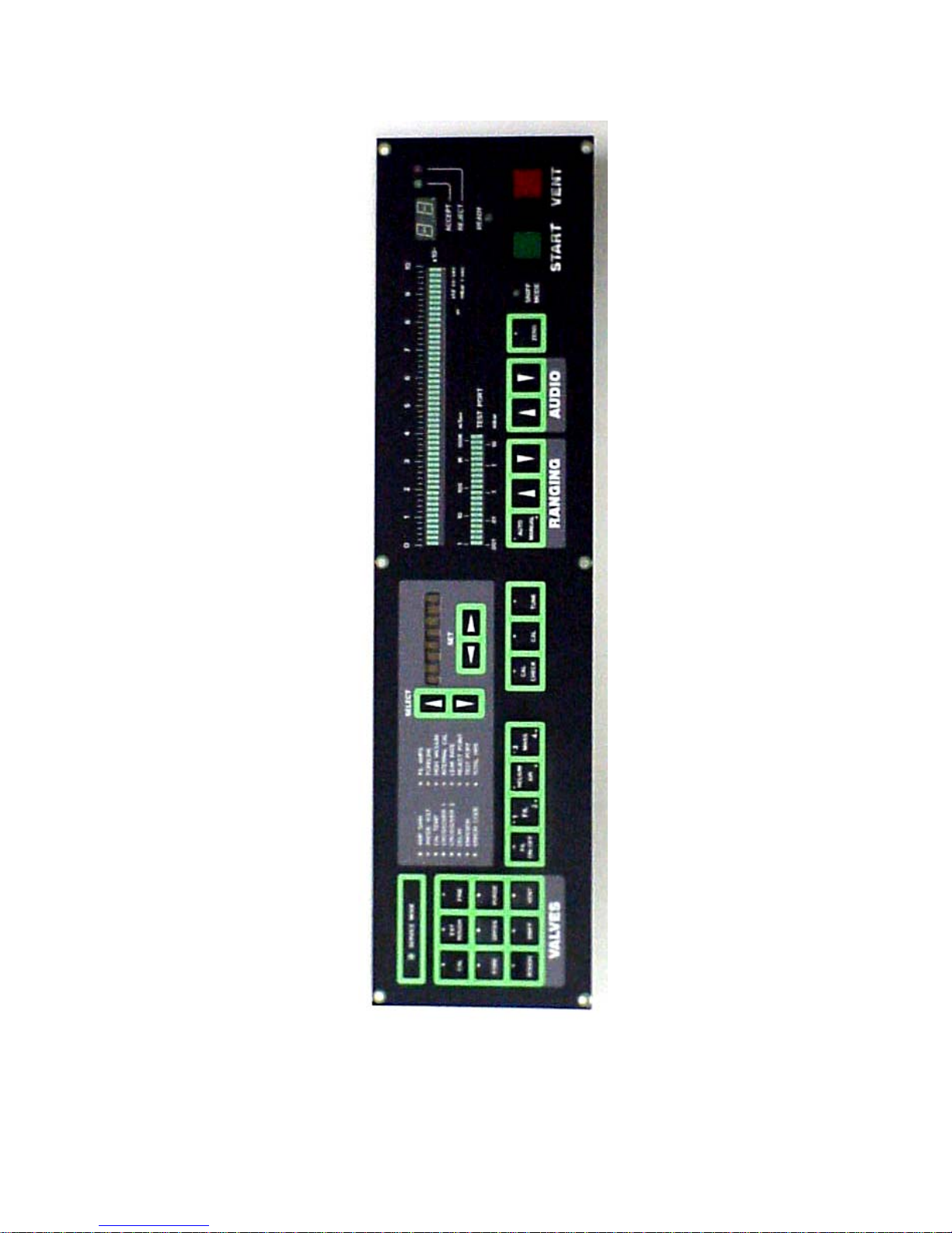
FIGURE 2 – 1
MS-40 USER PANEL
1109-186-00 Rev. C 2-2

n
2.2 Operator Controls & Indicators
The following Controls & Indicators are located on the User Panel at
the top right front of the unit. Items are listed from left to right, top to
bottom (see Figure 2-1 for an illustration of the User Panel).
LEAK RATE BAR GRAPH
An LED bar graph indicating the mantissa of the measured
leak rate of the test object. For a full leak rate reading, this
meter is used in conjunction with the Numeric Display. The
bar graph display is in standard cubic centimeters per second
or in millibar liters per second.
NUMERIC DISPLAY
A two-digit alphanumeric display with two separate functions.
During testing, the display will normally indicate the exponent
of the current leak rate. For example, if the leak rate is 3 x 10
-7
std cc/sec, the Leak Rate Bar Graph will indicate 3 while the
Numeric Display will indicate the number 7. The second
function of the display has been programmed to provide error
codes when a system fault has occurred (see Section 4.10 for a
list of error codes, their description and corrective action).
The display will indicate code EE while at the same time on
the Service Panel the Error Code indicator will be lit and the
Service Panel alphanumeric display will indicate the error
code.
TEST PORT
A bar graph that displays the pressure at the test port. Scaled
for either millitorr or millibar. The test port pressure is also
displayed in digital format on the Service Panel Alphanumeric
Display.
ACCEPT
During leak testing, this indicator will illuminate when the leak
measured is less than the programmed reject rate (or
maximum acceptable leak rate) and the unit is also in or below
the range of the reject value. The reject rate is set by the
user from the Service Panel (see Section 2.7).
VIC Leak Detectio
2099 Ninth Avenue
Ronkonkoma, NY 11779
631.737.0900
1109-186-00 Rev. C 2-3

REJECT
During leak testing, this indicator will illuminate when the leak
measured is greater than or equal to the programmed reject
rate (or maximum acceptable leak rate). The reject rate is
set by the user from the Service Panel (see Section 2.7).
READY
When lit, the unit is in standby mode (all valves except the
Fore-line valve are closed). Pressing the START pushbutton
commences a test cycle.
AUTO/MANUAL
Automatic/Manual Ranging. Prior to and during leak testing,
this momentary switch allows the user to toggle between
Automatic and Manual Ranging modes.
RANGING
While leak testing in Manual Ranging mode, each press of
either the up or down arrow buttons will cause the unit to leak
test in the decade (or range) above or below the current
decade being tested (pressing and holding either arrow button
will cause the unit to sequentially pass through one or more
decades). The numeric display (the exponent of the leak rate)
will indicate the change. Also, when leak testing in the
automatic ranging mode, pressing either arrow button will
force the unit to test in manual ranging mode, at a decade
higher or lower than the decade previously being tested
(corresponding to the arrow key pressed).
AUDIO
During actual testing and while in service mode, the audio
signal of the unit is always turned on. The arrow keys
dedicated to the Audio section of the panel control the
volume. Pressing the down arrow key several times (or
pressing and holding the down arrow key) reduces the volume
to an inaudible level. Note that this function is also available
when using the optional headphones. A connector for a set of
headphones is located under the bottom rear panel of the unit.
Vacuum Instrument Corp.
2099 Ninth Avenue
Ronkonkoma, NY 11779
631.737.0900
1109-186-00 Rev. C 2-4

C Leak Detectio
n
VacuuVIm Instrument Corp.
2099 Ninth Avenue
2099 Ninth Avenue
Ronkonkoma, NY 11779
Ronkonkoma, NY 11779
631.737.0900
631.737.0900
ZERO
In Standard Mode, The ZERO momentary switch is active
only during actual leak testing. When pressed, this unit’s
computer reduces the measured leak rate displayed by the unit.
To zero within the decade being measured (e.g., a 4 x 10
cc/sec leak rate would now be displayed as a 0 x 10
-6
std
-6
std
cc/sec leak rate). This function is usually used when
background helium causes measurement problems during
testing. Note that this function also limits the maximum
sensitivity of testing to two decades (or ranges) below the
zeroed decade.
When the unit is in Service Mode, pressing the ZERO
momentary switch will toggle the turbo-molecular pump on or
off. When the ZERO LED indicator is lit, the turbo-molecular
pump is on.
SNIFF MODE INDICATOR
When lit, the unit has been placed in the Sniff Mode. When
in Standard Mode, the unit is placed in the Sniff Mode by
pressing the SNIFF valve momentary switch located on the
left of the Service Panel. When the unit has been placed in
Service Mode, pressing the SNIFF valve momentary switch
opens the Sniffer Valve.
WARNING
Never operate the MS-40 in Sniff Mode without the optional
Sniffer Assembly or without the standard plug in place on the
Sniffer Quick Connect Fitting (QCF). Running the unit without
covering the Sniffer QCF will cause a dramatic increase in fore-line
pressure within the unit, and will thereby cause the unit’s turbo molecular pump to rapidly shut down.
START
Pressing this pushbutton begins a test cycle. During testing,
pressing the START pushbutton again will halt all testing by
closing all vacuum system valves (except the fore-line valve).
This also places the unit into its standby (wait) mode.
Pressing the START pushbutton instead of the VENT
pushbutton eliminates the chance of the user inadvertently
venting the system (refer to the VENT function, below).
The START pushbutton lights when a test cycle has been initiated.
1109-186-00 Rev. C 2-5

Vacuum Instrument Corp.
Vacuum Instrument Corp.
2099 Ninth Avenue
2099 Ninth Avenue
Ronkonkoma, NY 11779
Ronkonkoma, NY 11779
631.737.0900
631.737.0900
VENT
Dual function pushbutton. When pressed momentarily, the
MS-40 is interrupted from its current testing cycle and placed
in standby (wait) mode. The green READY indicator will
light. When pressed and held for a preprogrammed time (as
programmed by the user; factory default is 0.5 second) the
pushbutton initiates an AUTO-VENT cycle and returns the
test port to atmospheric pressure. The delay may be
programmed for up to 999.9 seconds.
ON/OFF
Turns the MS-40 ON or OFF.
The following Controls & Indicators are accessible from the Service
Panel (the left half of the panel at the top front of the unit). Items are
listed from left to right, top to bottom (see Figure 2-1 for an illustration
of the Service Panel).
SERVICE MODE INDICATOR
When lit, the MS-40 has been placed in Service Mode. The
unit is placed in Service Mode by pressing the Service Mode
Interlock button located on the upper right side of the “A” circuit
board, mounted on the inside of the unit’s rear door.
AMP GAIN
Amplifier Gain. When this function is selected, the
alphanumeric display indicates the setting of the leak rate
amplifier (1.0 to 10.0).
Five different gains are used on the unit. The first, G1,
is used for the unit’s gross flow mode; the second, G2, is
used for the unit’s reverse flow mode and the third G3, is
used for the unit’s direct flow mode. G4 and G5 are used
for sniff mode.
The five different gain settings can be displayed using
the SELECT momentary switches when the AMP GAIN
function has been selected. Gain (calibration) of
the MS-40 is changed by the SET momentary switches.
Normally G2 and G3 are set automatically by the
MS-40 during a Tune and Calibration cycle, however
the G2 and G3 settings can be manually altered in
Service Mode. The actual setting may be viewed in either
1109-186-00 Rev. C 2-6

n
Service or Standard Modes. Note that G1, G4 and G5 are not
controlled by the MS-40 and must be set by the user. G1 may
be set by the user when the MS-40 is leak testing in the Gross
Mode, or when the unit is in the service mode. G4 and G5 can
be set when the unit is in sniff testing mode.
ANODE VOLT
Anode Voltage. When this function is selected, the
alphanumeric display indicates the anode voltage of the unit.
In Service Mode, the anode voltage may be altered
incrementally by pressing either of the SET momentary
switches. Note that the other peak voltages associated with
the mass spectrometer follow the anode voltage setting;
therefore the MS-40 can be manually tuned by changing the
peak voltage.
CAUTION
Only qualified personnel should attempt to alter the anode voltage
setting while the unit is in Service Mode. As stated above, altering
the peak tuning voltages will retune the mass spectrometer. Improper
tuning will greatly effect the accuracy and reliability of the leak
detector.
While the unit is in Standard Mode, pressing either the left or
right SET momentary switches adjusts the unit’s peak tuning
voltages either -30 or +30V. This function, unique to
VIC’s MS series of leak detectors, is referred to as peak scan
and is used to quickly verify if the mass spectrometer is
properly tuned (refer to Section 2.9 for further information on
the Peak Scan function). Releasing either momentary switch
returns the anode voltage of the unit to its original value.
CAL TEMP
Calibrator Temperature. When selected in Standard Mode, the
alphanumeric display will indicate the current temperature of
the calibrator. When selected in Service Mode, the
alphanumeric display will indicate the temperature at which
the internal helium reference standard was originally
calibrated. This parameter may be altered in Service Mode
(using the SET pushbuttons), however, this setting should
not be altered unless a new calibrator is installed in the unit.
VIC Leak Detectio
2099 Ninth Avenue
Ronkonkoma, NY 11779
631.737.0900
1109-186-00 Rev. C 2-7

CROSSOVER 1
The alphanumeric display indicates the programmed test port
pressure needed to crossover from the unit’s gross testing
mode to reverse testing mode (when using the optional
external pump). If an external pump is not connected to the
unit, the crossover set point is the pressure needed to crossover
from the unit’s roughing mode to the reverse testing mode.
This parameter may be altered while the unit is in either
Standard or Service Mode, by using the SET momentary
switches.
CROSSOVER 2
The alphanumeric display indicates the programmed test port
pressure needed to crossover from the unit’s reverse testing
mode to its direct testing mode. This parameter may be
altered while the unit is in either Standard or Service Mode,
by using the SET momentary switches.
DELAY
Seven delay settings are available and may be set while the unit is in
Standard mode:
D1/Fine (Direct) Crossover Delay: The time delay after
Crossover 2 has been reached and the onset of Direct testing.
The MS-40 stays in Reverse Flow during this time. The
factory default is 1.0 second; the parameter may be set between
0.1 to 999.9 seconds. Note that if the MS-40 is set for Manual
ranging in the 10
-10
range, the unit will remain in the
roughing state for the time set in D1 after Crossover 2
has been reached.
D2/Direct Rough Valve Close Delay: When Crossover 2
has been reached, the Rough valve will remain open for
this value and will then close. The factory default is 0.1
second; the parameter may be set between 0.1 to 999.9
seconds. If D2 is set to 999.9 seconds, the Rough valve
will remain open for the entire length of the test cycle.
Vacuum Instrument Corp.
2099 Ninth Avenue
Ronkonkoma, NY 11779
631.737.0900
1109-186-00 Rev. C 2-8

Vacuum Instrument Corp.
Vacuum Instrument Corp.
2099 Ninth Avenue
2099 Ninth Avenue
Ronkonkoma, NY 11779
Ronkonkoma, NY 11779
631.737.0900
631.737.0900
D3/Vent Delay: The amount of time needed to hold the
VENT pushbutton before the venting cycle begins. The
factory default is 1.0 seconds; the parameter may be set
between 0.1 to 999.9 seconds.
D4/Vent Duration: The amount of time the vent valve
will stay open after the unit’s Pirani gauge indicates
atmosphere has been reached. The factory default is 1.0
second; the parameter may be set between 0.1 to 999.9
seconds. If D4 is set to 999.9 seconds, the Vent valve
will remain open until next test cycle is started.
D5/Minimum Gross Testing Time: May be set from 1.0
to 999.9 seconds; the factory default is 1.0 second. Sets
the minimum amount of time that the MS-40 will remain
in the Gross test mode. Prevents unit from auto ranging
and crossing over into Reverse flow mode before a gross
leak is detected. Useful when testing large parts that may
have a long helium response time.
D6/Minimum Rough Time: May be set from 1.0 to 999.9
seconds; the factory default is 1.0 second. Specifies minimum
amount of time that MS-40 will remain in Roughing state before
crossing over into a testing state. Useful for testing parts with high
gas load which require extended pumping.
D7/Reverse Rough Close Delay: May be set from 0.1 to
999.9 seconds; the factory default is 0.1 second. If set to 999.9
seconds, external Rough valve will remain open for entire
duration of reverse flow testing. Keeps external Rough valve open
for specified amount of time after reverse flow valve has opened.
Only active on units equipped with external Rough valve option.
NOTE:
In Service mode, the delay function displays:
D1: the current software version stored in flash memory (e.g.,
FLASH 4.3).
D2: the current software version stored in ROM (e.g.,
EPROM 1.5).
1109-186-00 Rev. C 2-9

n
VIC Leak Detectio
2099 Ninth Avenue
Ronkonkoma, NY 11779
631.737.0900
D3: 10
-7
range electrical offset; expressed as a fraction of a
volt (e.g., 0.00xx).
D4: 10
-10
range electrical offset; expressed as a fraction of a
volt (e.g., 0.00xx).
D5: Same as in Standard mode
D6: Same as in Standard mode
D7: Same as in Standard mode
EMISSION
Emission Current. Indicates the filament emission current.
The alphanumeric display will indicate the current in mA. A
normally operating filament will have an emission current of
5mA, as regulated by the filament control circuit.
ERROR CODE
This function automatically appears after an error has occurred
with the unit. When an error occurs, the alphanumeric display
automatically switches to this function and displays the error code.
The unit will display the code until the problem is resolved. This
Function is also selectable when using the SELECT momentary
switches on the Service Panel. If in Standard Mode, and this
function is selected when a system error has not occurred, the
word “NONE” will appear on the alphanumeric display. In
Service Mode, selecting this function will display the current date.
FIL CURRENT
Filament Current. The alphanumeric display indicates the
filament supply current, in D.C. Amps. The maximum current
is 6.3 amps.
FORE-LINE
Fore-line Pressure. The alphanumeric display indicates fore-line
pressure. May be displayed in millitorr or millibar. The
selection of units to be displayed is made by a blue toggle
switch located underneath the Service Panel. The switch is
accessed by opening the front panel and is mounted on the
circuit board located directly under the Service Panel.
1109-186-00 Rev. C 2-10

HIGH VACUUM
The alphanumeric display indicates pressure in the high vacuum section (the area surrounding the filament within the
spectrometer housing). If the unit’s filament has been turned
off, the display will state OFF, otherwise the display
indicates the high vacuum pressure in either Torr or bar. The
selection of units to be displayed is made by a blue toggle
switch located underneath the Service Panel. The switch is
accessed by opening the front panel and is mounted on the
circuit board located directly under the Service Panel. If the unit is in
Standby mode, the alphanumeric display will occasionally display
“MS-40”. When this occurs, the unit is checking system offsets and
not measuring Hi-Vac pressure.
INT CALIBRATOR
Internal Calibrator. In Service Mode the alphanumeric display
indicates the leak rate value stored in the unit’s computer for
the internal calibrator. This parameter may be altered only in
Service Mode, by using the SET momentary switches. This
parameter should only be changed when the internal calibrator
has been replaced. Note that when the unit is in Standard
Mode, this function will display the current temperature compensated value of the internal calibrator. This parameter
may not be changed, since this value is derived from the leak
rate value of the internal calibrator.
LEAK RATE
The alphanumeric display indicates the actual current leak
rate. Measurement is in either std cc/sec or millibar liter/sec.
REJECT POINT
The alphanumeric display indicates the programmed leak rate
value for the Reject/Accept indicator (the set point that
indicates if the test object is below the maximum acceptable
leak rate). This parameter may be altered only in Standard
Mode, by using the SET pushbuttons. In Service Mode, this
function is used to indicate the speed of the turbo-molecular
pump (the alphanumeric display indicates the percentage of
the pump’s rated speed).
Vacuum Instrument Corp.
2099 Ninth Avenue
Ronkonkoma, NY 11779
631.737.0900
1109-186-00 Rev. C 2-11

p
TEST PORT
Test Port Pressure. The alphanumeric display indicates the
pressure of the test port. May be displayed in millitorr or
millibar. The selection of units to be displayed is made by a
blue toggle switch located underneath the Service Panel. The
switch is accessed by opening the front panel and is mounted
on the circuit board located directly under the Service Panel.
TOTAL HRS
Total Hours. In Standard Mode, the alphanumeric display
indicates the total number of hours the unit has been in
operation. In Service Mode, the display indicates the time of
day. The time (a 24 hour clock) can be altered by using the
SET arrow keys (to select hrs, min. and sec.) and the AUDIO
arrow keys to set the new time for the unit.
SELECT
Up/Down Arrow Keys. Momentary switches that allow the
user to scroll through the sixteen functions located on the
Service Panel. The LED next to each function indicates the
function that has been selected. The selected function’s
readout is displayed on the alphanumeric display.
ALPHANUMERIC DISPLAY
Eight character display. Used to indicate messages as well as
the status of the sixteen selectable functions on the Service
Panel (from AMP GAIN to TOTAL HRS). An LED next to
the function indicates that the function has been selected,
while this display indicates its current status or measurement.
The display also indicates Error Message Codes (see Section
4.x for a list of Error Codes).
SET
Up/Down Arrow Keys. Momentary switches that allow the
user to increase or decrease the value of the settable
functions (AMP GAIN, ANODE VOLTAGE, CAL TEMP,
CROSSOVER 1, CROSSOVER 2, DELAY, INT
CALIBRATOR and REJECT POINT).
Vacuum Instrument Cor
Vacuum Instrument Corp.
2099 Ninth Avenue
2099 Ninth Avenue
Ronkonkoma, NY 11779
Ronkonkoma, NY 11779
631.737.0900
631.737.0900
.
1109-186-00 Rev. C 2-12

n
FIL ON/OFF
Filament ON/OFF. Momentary switch. When the unit is in
Service Mode, pressing this switch will toggle the active
filament on or off.
When the unit is in Standard Mode, this switch also toggles
the active filament on or off. However, whenever the unit is
in Standard Mode, the filament may be turned on only when
the high-vacuum section has been sufficiently evacuated (as
determined by the MS-40’s computer).
CAUTION
As described above, in Service Mode, the spectrometer’s filament
may be turned on or off at any time. In this mode, care should be
taken to make sure that the high-vacuum section has been
pumped down. If the filament is turned on when the highvacuum section is at or near atmosphere, the filament will
quickly burn out.
FIL 1/2
Filament 1 or 2.Momentary Switch. By pressing this switch,
the user can toggle between Filament 1 and 2. A green indicator
next to the 1 or 2 on this switch indicates that the respective
filament is working properly. If a red LED appears next to the
1 or 2 on the switch, the filament is malfunctioning.
HELIUM/AIR
Momentary Switch. Not active in Standard Mode. By
pressing this switch in Service Mode, the user can toggle
between air-equivalent and helium leak rate readings.
The LED next to the HELIUM or AIR labels indicates which
standard is active.
MASS 3/4
Momentary Switch. Not active in Standard Mode. By
pressing this switch in Service Mode, the user can toggle
between Mass 3 or Mass 4 helium tuning voltages. The
LED next to the 3 or 4 indicates whether Mass 3 or Mass 4
is selected.
VIC Leak Detectio
2099 Ninth Avenue
Ronkonkoma, NY 11779
631.737.0900
1109-186-00 Rev. C 2-13
 Loading...