

Page 1

MPS-3000 CE
Power Supply
Technical Manual
425964
Page 2

MPS-3000 CE
Power Supply
Technical Manual
Page 3

© 2003 Veeco Instruments Inc. All rights reserved.
Veeco Instruments Inc.
2330 E. Prospect Road, Ft. Collins, CO 80525
970.221.1807
The information contained in this document is believed to be accurate and reliable. However, Veeco Instruments Inc. cannot accept
any financial or other responsibilities that may result from the use of this information. No warranties are granted or extended by this
document.
It is the policy of Veeco Instruments Inc. to improve products as new technology, components and materials become available. Veeco
Instruments, Inc. therefore reserves the right to change specifications without prior notice.
This manual is intended for qualified personnel who are responsible for servicing and or running Veeco Instruments Inc. ion beam
processing systems and equipment. The information contained in this manual is the sole property of Veeco Instruments Inc. and may
not be reproduced, distributed, or transmitted in any form without the written permission of Veeco Instruments Inc.
Manual #425964 Rev.E
Page 4

Table of Contents
Safety 1
Overview 4
Installation 6
Controls 8
Manual Operation 23
Local Operation 42
Other Modes of Operation 45
Serial Communications 46
Maintenance 65
Troubleshooting/Error Code Definitions 69
Service Support 73
Specifications 74
Tables 83
Environmental Safety 84
Drawings 85
Filament Cathode with Filament Neutralizer or PBN Option 86
Hollow Cathode and HCN - 7 pin or 2 x 4 pin feedthrough 87
Hollow Cathode and Hollow Cathode Neut - 6 pin feedthrough 88
Filament Cathode with Filament Neutralizer or PBN Option 89
3cm Source Filament Cathode and Filament Neutralizer 90
3cm Source Hollow Cathode and Hollow Cathode Neutralizer 91
3cm Source Plasma Bridge Neutralizer 92
Page 5
Chapter 1: Safety
DANGER
WARNING
CAUTION
Understanding the correct installation, operation, and maintenance procedure is necessary for safe and successful operation. This safety alert symbol
precedes safety messages in this manual, along with one of the three signal
words explained below. Obey the messages that follow these words to
avoid possible injury or death.
This symbol marks an imminent hazard which will kill or injure if ignored.
This symbol marks a potential hazard which may kill or injure if ignored.
This symbol marks a potential hazard which may cause minor injury if
ignored.
CAUTION
This symbol marks a potential hazard which may cause damage if ignored.
Symbols Used on the Unit
Refer to manual
Designates a chassis ground
Designates a protective earth grounding point
1
Page 6

Dangerous voltage
WARNING
WARNING
WARNING
Unit in standby - power outputs deactivated
Unit on - power outputs active
Unit off - power off
Please read the following before continuing:
To avoid electrical shock, keep clear of “live” circuits. Follow all local lockout/tag-out procedures, before repairing or replacing any electrical
devices.
It is recommended that only trained, qualified persons using established
safety procedures perform any work related to the installation, start-up,
operation or maintenance of this system.
To avoid electrical shock, check that all hardware interlocks are working.
Keep all guards and panels in place during routine system operation.
Complete ion beam systems from Veeco Instruments Inc. are supplied with
hardware interlocks and software safeguards at various points in the system. Whenever components or retrofits are added to existing systems, a
local review of system safety is recommended.
To avoid safety feature impairment and possible injury, the operator must
use this equipment in the manner specified by Veeco Instruments Inc.
The CE I/O Signal Isolation Sub-chassis, attached to the MPS-3000 CE
power supply rear panel, incorporates the isolation circuitry for the user
accessible EIA-232 and system interlock circuits. The integral I/O signal
2
Page 7

isolation circuit incorporates optical transmitters and photo detectors,
which are coupled together by fiber optic cables. This configuration ensures
that the user accessible EIA-232 and system interlock circuits remain at
Safety Extra Low Voltage (SELV) under normal and single fault conditions.
The customer side supply (+5V DC) is generated from an integral isolating
type DC/DC inverter that inverts the ELV +15V DC supply to the required
SELV +5V DC supply.
3
Page 8

Chapter 2: Overview
The MPS-3000 CE power supply system is specifically designed and optimized to power and control Veeco ion beam sources.
• The built-in microprocessor provides reliability and flexibility to
the user. The microprocessor automatically checks each of the
power supplies each time the system is turned on.
• When an unsatisfactory condition occurs, an error code
appears on the power supply display. Refer to “Troubleshoot-
ing/Error Code Definitions” on page 69 to determine the
cause and remedy to the problem.
• Programmable limits on the power supplies allow the users to
adjust the system. On the neutralizer power supply, the filament current limit might be adjusted up or down as required,
depending upon the size and type of filament wire used.
• Operate in Manual, Local, Local Restricted, or Remote mode.
Manual Mode
Each of the individual power supplies is controlled from the front panel.
Recall or store complete operating conditions from one of two nonvolatile
memories.
Use these steps to change a parameter:
1. Select a power supply with the MODULE select switch.
2. Select a parameter with the FUNCTION select switch.
3. Turn the Adjust knob to reach the chosen value.
Local Mode
Beam voltage, beam current, and accelerator voltage are adjustable from
the front panel when operating in Local mode. Recall or store two complete
sets of operating conditions from the two nonvolatile memories.
Local Restricted Mode
No adjustments may be made to any parameters from the front panel.
Recall operating conditions from the memory.
4
Page 9

Operating conditions may not be stored in the memory when operating in
NOTE
Local Restricted mode.
Remote Mode
No adjustments may be made to any parameter from the front panel.
Operating conditions may not be stored from the front panel and conditions may not be recalled from the memory when operating in Remote
mode.
By using an EIA-232
1
interface, a computer may control power supplies
and may recall conditions from memory.
•The MEMORY, MODULE, and FUNCTION select switches are
nonfunctional in Remote mode.
•The SOURCE and BEAM switches may be turned off, but may
not be turned on at the front panel.
•The KEYLOCK switch may “lock” the power supply into any of
the modes.
• When in the Disable position, the mode may not be changed.
1. Formerly known as, and identical to RS-232. The EU equivalent is
CCITT V.24
5
Page 10

WARNING
CAUTION
WARNING
Chapter 3: Installation
To avoid electrical shock, keep clear of “live” circuits. Follow all local lockout/tag-out procedures before installing any electrical devices.
Single Power Supply System Assembly
The MPS-3000 CE power supply is designed for rack mount. It is shipped
with the rack mount brackets attached.
1. Install the unit in the chosen location.
If cabinet installation is chosen, use the four holes in the rack mount
brackets to attach the unit to a cabinet.
Do not obstruct the cooling ports on the MPS-3000 CE power supply. An
insufficient supply of cooling air will result in the unit overheating, causing
a thermal shutdown and possible damage.
The power supply’s cooling air ports are located in the sides of the
chassis, and the cooling fan port is located in the rear panel of the
chassis.
2. Connect the following:
a. The source/beam cable to the source/beam connector (P33)
located on the unit’s back panel.
b. The neutralizer cable to the neutralizer connector (P32) located on
the unit’s back panel.
c. The interlock cable to the interlock connector (DB9) located on the
unit’s back panel.
d. The source/beam cable to the ion beam source (refer to “Draw-
ings” on page 85).
e. The neutralizer cable to the ion beam source (refer to “Drawings”
on page 85).
The shield in the source cable must be attached to facility ground with a
low impedance connection. If the cable is not attached correctly, the power
supply and facility may float at high voltages.
3. Connect the wires attached to pins 1 and 6 on the interlock cable to
the series-connected external interlock circuitry.
6
Page 11

The external interlock conditions are met when all series switches are
NOTE
NOTE
closed. The number and type of interlock switches differ from system to system.
Use only dry closure (relay) contacts in the interlock circuit.Interlock wiring should have a minimum insulation rating of 100V DC per lead;
these leads should be shielded, with a drain wire attached to a metallic
connector shell. An insulating sheath covering the leads, shield and
drain wire shall have a minimum insulation rating of 300V DC.
Do not connect the external interlock circuit to a powered circuit.
CAUTION
4. Verify that the POWER ON/OFF switch (on the power supply front) is in
the STANDBY position and that the CB1 circuit breaker (on the power
supply rear panel) is in the OFF position.
5. Connect the unit’s line cord to an appropriate power source. See
“Specifications” on page 74.
• If connecting to a three-wire power service with two hot lines
and facility ground, the power cord is wired as follows:
Service Power Supply
Hot Blue (White)
Hot Brown (Black)
Ground Green/Yellow
• If connecting to a three-wire power service with one hot line, a
neutral line, and earth, the power cord is wired as follows:
Service Power Supply
Hot Brown (Black)
Neutral Blue (White)
It is the user’s responsibility to meet all local and national electrical codes
when installing this equipment.
6. Turn the CB1 circuit breaker on the power supply’s rear panel to the
This completes installation of a single power supply.
Earth Green/ Yellow
ON position.
• If the unit interfaces with an external microprocessor, refer to
“Serial Communications” on page 46, for correct installation.
7
Page 12
Chapter 4: Controls
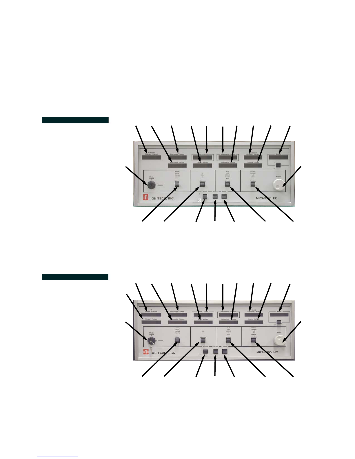
The numbers in FIGURE 4.1 through FIGURE 4.3 will appear throughout to
identify the power supply’s controls as their use and function is referenced.
FIGURE 4.1 Front
Panel: MPS-3000 CE FC
FIGURE 4.2 Front
Panel: MPS-3000 CE HC
4
21
10
20
12
11
14
13 15
16
17
18
19
9
5
12
6
11
14
1
13 15
2
3
16
22
7
23
8
19
4
5
6
1
2
3
7
9
8
8
Page 13
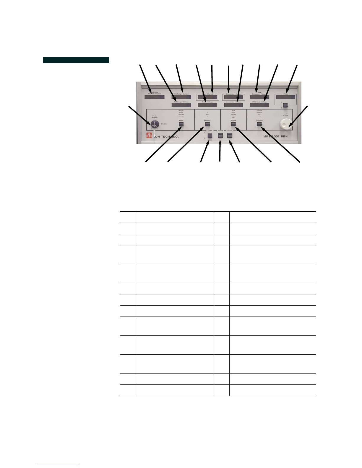
FIGURE 4.3 Front
Panel: MPS-3000 CE
PBN
10
12
11
14
13 15
16
24
25
4
5
6
1
2
3
7
19
9
8
Table 4.1: MPS-3000 CE FC/HC/PBN Front Panel Keys and Switches
1 Power On/Standby 14 Beam Voltage Display
2 Source On/Off 15 Accelerator Current Display
3 Beam On/Off 16 Accelerator Voltage Display
4Keylock 17
5Mode 18
Neutralizer Emission Current
Display
Neutralizer Filament Current
Display
6 Memory 19 Not used
7 Module 20 HC Heater Current Display
8 Function 21 HC Keeper Voltage Display
9Adjust 22
Cathode Filament Current
10
Display
11 Discharge Current Display 24
HCN Emission/Heater Current Display
23 HCN Keeper Voltage Display
PBN Emission/Filament Current Display
12 Discharge Voltage Display 25 PBN Body Voltage Display
13 Beam Current Display
9
Page 14

Power - On/Standby (1)
The POWER switch controls the AC power to the unit and is controllable in
all modes of operation. When the POWER switch is turned on, the following
occurs:
• Power is applied to the controller board and to all the displays
on the display board. The test program is initiated.
• After about six seconds the main contactor is energized. Each
power supply is checked. The letter “P” will appear on the
upper display of that power supply.
Source - On/Off (2)
The SOURCE switch applies power from the Cathode, Discharge, and
Neutralizer power supplies to the appropriate pins of the neutralizer connectors (P33 and P32), located on the power supply’s rear panel.
• The word SOURCE appears above the switch indicating the
SOURCE switch has been selected.
•The SOURCE switch may be turned off in any mode.
• While in Remote mode, the SOURCE switch may be turned on
through the remote device.
• In any other mode, the SOURCE switch may be controlled
from the front panel.
Beam - On/Off (3)
The BEAM switch applies power from the Beam and Accelerator power supplies to the appropriate pins of the source connector (P33) located on the
power supply’s rear panel.
• The word BEAM appears above the switch indicating the
BEAM switch has been selected.
• While in Manual, Local, and Local Restricted modes, the beam
may be turned on only if the source is already on.
•The BEAM switch may be turned off in any mode.
• While in Remote mode, the BEAM switch may be turned on
through the remote device.
• In any other mode, the BEAM switch may be controlled from
the front panel.
10
Page 15

Keylock (4)
The KEYLOCK switch enables or disables the MODE switch.
• In the disable position, the MODE switch will not function, and
the active mode will be locked in.
•The KEYLOCK switch must be in the enable position to change
the mode of operation.
Mode (5)
The MODE switch selects the power supply’s operation mode.
•The KEYLOCK switch must be in the Enable position to change
from one mode to another.
Manual
All parameters, except beam current, may be adjusted from the front
panel.
• Operating conditions may be stored or recalled from memory.
• All switches on the front panel are active in this mode.
• The word MANUAL appears indicating that Manual mode has
been selected.
Local
Only the following parameters may be adjusted: beam voltage, beam
current, accelerator voltage, and A/B Ratio when in Local mode. All
remaining parameters may not be changed from the front panel.
• The micro-processor controls the non-adjustable parameters
to obtain the programmed values.
• Operating conditions may be stored in or recalled from memory.
• All the front panel switches are active in this mode.
• The word LOCAL appears above the MODE switch indicating
that Local mode has been selected.
Local Restricted
No parameter may be adjusted in this mode. However, parameters may
be recalled from memory.
• The enunciators above the FUNCTION and MODULE
switches will be dark when in Local Restricted mode.
• The letters LOC RES appear above the MODE switch.
• All switches, except the FUNCTION and MODULE switches,
are active in this mode.
11
Page 16

Remote
Allows the unit to be controlled by a computer. The computer may
select the Remote mode, recall conditions from either memory, and turn
the SOURCE and BEAM switches on or off.
• All adjustable parameters may be changed through the remote
microprocessor.
• In Remote mode, the SOURCE and BEAM switches may be
turned off but may not be turned on at the front panel.
•The KEYLOCK, MODE, and POWER switches are fully functional, while the MEMORY, MODULE, and FUNCTION
switches are not functional.
• The word REMOTE appears above the MODE switch indicating that Remote mode has been selected.
Memory (6)
Selects one of the two sets of parameters that are stored in memory. The
MEMORY switch is active in all modes, except Remote.
MEM 1
When the number 1 appears above the MEMORY switch, the power
supply will operate from memory location one. When any parameter is
changed, the new value will be stored automatically in MEMORY 1.
MEM 2
When the number 2 appears above the MEMORY switch, the power
supply will operate from memory location two. When any parameter is
changed, the new value will be stored automatically in MEMORY 2.
RCL
When Recall has been selected, the parameters will be displayed from
the memory location not being used. While the parameters are being
recalled from a memory location, the letters RCL appear above the
MEMORY switch. After about four seconds, the displays will return to
their previous readings. The running conditions will not be affected by
selecting Recall.
12
Page 17

Module (7)
NOTE
Selects the power supply that may have changes made to its parameters.
The MODULE switch is active in Manual or Local mode only. In Local
Restricted or Remote mode, the enunciators above the MODULE switch will
be dark.
Beam
The word BEAM appears above the MODULE switch indicating that
Beam power supply has been selected.
• Beam voltage may be adjusted in Manual, Local or Remote
mode.
• Beam current may be adjusted in Local or remote mode.
Accel
The letters ACCEL appear above the MODULE switch indicating that
Accelerator power supply has been selected.
• The accelerator voltage may be adjusted in Manual, Local or
Remote mode.
• The A/B Ratio may be adjusted in Manual, Local, or Remote
mode.
Discharge
The letters DISCHRG appear above the MODULE switch indicating that
Discharge power supply has been selected.
• MPS-3000 CE FC, PBN, and HC: The discharge current limit
may be selected and adjusted in Manual or Remote mode.
• MPS-3000 CE FC and PBN: The discharge voltage may be
selected and adjusted in Manual mode or may be adjusted
through a remote microprocessor.
• MPS-3000 CE HC: The discharge current may be selected
and adjusted only in Manual mode.
Cathode
The Cathode power supply is part of the MPS-3000 CE FC and PBN.
• The word CATHODE appears above the MODULE switch indicating that Cathode power supply has been selected.
• Cathode filament current and current limit are adjustable in
Manual mode and through a computer.
The filament current may not be adjusted above the programmed current
limit value, and the limit value may not be adjusted below the target filament current.
13
Page 18

HC
NOTE
The HC power supply is part of the MPS-3000 CE HC.
• The letters HC appear above the MODULE switch indicating
that Hollow Cathode power supply has been selected.
• The hollow cathode keeper voltage limit is the only adjustable
parameter on the Hollow Cathode power supply.
• The keeper voltage limit may be adjusted in Manual mode or
through a remote microprocessor.
NEUT
The Neutralizer power supply is part of the MPS-3000 CE FC.
• The letters NEUT appear above the MODULE switch indicating
that Neutralizer power supply has been selected.
• Neutralizer filament current and current limit are adjustable in
Manual mode and through a computer.
HCN
The HCN power supply is part of the MPS-3000 CE HC.
• The letters HCN appear above the MODULE switch indicating
that Hollow Cathode Neutralizer power supply has been
selected.
• The heater current may be viewed by selecting HEATER with
the FUNCTION switch in Manual or Local mode.
PBN
The PBN power supply is part of the MPS-3000 CE PBN
• The letters PBN appear above the MODULE switch indicating
that PBN power supply has been selected.
• The PBN filament limit may be adjusted either in Manual mode
or through a remote computer.
• The emission current may be adjusted only in Manual mode.
• The PBN filament current may be viewed in Manual or Local
mode by selecting LIMIT with the FUNCTION switch.
Do not adjust the filament current limit below the actual filament current.
14
Page 19

Function (8)
Selects the parameter to adjust.
•The FUNCTION switch is active only in Manual or Local
mode. The enunciators above the FUNCTION switch will be
blank when in Local Restricted or Remote mode.
Voltage
For an MPS-3000 CE FC power supply, voltage is adjustable for the
Beam, Accelerator, or Discharge power supply. The word VOLTAGE
appear above the FUNCTION switch.
For an MPS-3000 CE HC power supply, voltage is adjustable for the
Beam and Accelerator power supplies only. The word VOLTAGE
appears above the FUNCTION switch.
Current
MPS-3000 CE FC: The current is adjustable only when the Neutralizer
or Cathode power supply has been selected.
MPS-3000 CE HC: The current is adjustable only when the Hollow
Cathode Neutralizer or Discharge power supply has been selected.
MPS-3000 CE PBN: The current is adjustable only when the Cathode
or PBN power supply has been selected.
The beam current may be selected when operating in Local mode. The
word CURRENT appears above the FUNCTION switch indicating that
beam current has been selected.
A/B Ratio
The A/B Ratio may be adjusted only when the Accelerator power supply
has been selected when operating in Manual or Local mode.
• The letters A/B appear above the FUNCTION switch indicating that A/B Ratio has been selected. The A/B Ratio may also
be adjusted through a computer.
Limit
MPS-3000 CE FC, HC, or PBN: The limit is adjustable, when the Cathode, Neutralizer or Discharge power supply has been selected.
• The word LIMIT appears above the FUNCTION switch. Limits
may be adjusted in Manual mode or through a computer.
MPS-3000 CE PBN: The PBN filament current may be viewed when in
Local mode. Select PBN and LIMIT with the MODULE and FUNCTION
switches.
Heater
The letters HCN appear above the module switch indicating that Hollow Cathode Neutralizer has been selected. The word HEATER appears
above the FUNCTION switch.
15
Page 20

Adjust Knob (9)
The Adjust knob is used to change the value of a selected parameter.
• Turning the knob clockwise increases the parameter value.
• Turning the knob counterclockwise decreases the parameter
value.
If the selected power supply is off, the target parameter will be changed by
turning the Adjust knob, and changes may be viewed on the appropriate
display.
• When the selected power supply is operating and the Adjust
knob is turned, the target parameter will be changed, but the
power supply will react to the new parameter immediately.
• Target parameters are displayed while the knob is being
turned.
• Actual values are displayed when the knob is not being turned.
• Anytime the knob is turned, the new value is stored automatically in the selected memory.
Cathode Filament Current Display (10)
Indicates the amount of current supplied from the Cathode power supply
for heating the cathode filament.
Discharge Current Display (11)
Displays the amount of electron current collected by the ion source anode.
Discharge Voltage Display (12)
Displays the amount of voltage (positive with respect to the cathode)
applied to the ion source anode.
Beam Current Display (13)
Displays the amount of ion current being extracted from the ion source.
Beam Voltage Display (14)
Displays the amount of voltage (positive with respect to facility ground)
applied to the ion source.
Accelerator Current Display (15)
Indicates the amount of current being collected by the accelerator (downstream) extraction grid.
16
Page 21

Accelerator Voltage Display (16)
Indicates the amount of voltage (negative with respect to facility ground)
applied to the accelerator (downstream) extraction grid.
Neutralizer Emission Current Display (17)
Indicates the amount of electron emission current being supplied by the
neutralizer power supply into the ion beam.
Neutralizer Filament Current Display (18)
Indicates the amount of current being supplied by the neutralizer power
supply for heating of the neutralizer filament.
Probe (19)
This feature is not active at this time.
HC Heater Current Display (20)
Indicates the amount of current provided by the Hollow Cathode power
supply for heating the internal hollow cathode.
HC Keeper Voltage Display (21)
Indicates the amount of keeper voltage necessary for the operation of the
internal hollow cathode or shows the setting of the keeper voltage limit.
• When the letters HC is selected on the MODULE switch and
LIMIT is selected on the FUNCTION switch, the keeper voltage
limit will be displayed.
HCN Emission / Heater Current Display (22)
Indicates the emission current or heater current parameters. The display will
show emission current unless HEATER is selected by the FUNCTION switch.
• The emission current indicates the amount of current being
provided by the Hollow Cathode Neutralizer power supply to
neutralize the ion beam.
• The heater current display indicates the amount of current provided by the Hollow Cathode Neutralizer power supply for
heating the internal hollow cathode neutralizer.
HCN Keeper Voltage Display (23)
17
Page 22
Indicates the amount of keeper voltage necessary for the operation of the
internal hollow cathode neutralizer or shows the setting of the keeper voltage limit.
• When HCN is selected on the MODULE switch and LIMIT is
selected on the FUNCTION switch, the keeper voltage limit is
displayed.
• When HCN is the module selection and LIMIT has not been
selected with the MODULE switch, the actual keeper voltage
will be displayed.
PBN Emission / Filament Current Display (24)
Indicates one of two parameters: emission current or filament current. The
display will show emission current unless PBN and LIMIT have been
selected by the MODULE and FUNCTION switches.
• The emission current indicates the amount of current being
provided by the Plasma Bridge Neutralizer power supply to
neutralize the ion beam.
• The filament current display shows the amount of current
being provided to heat the PBN filament.
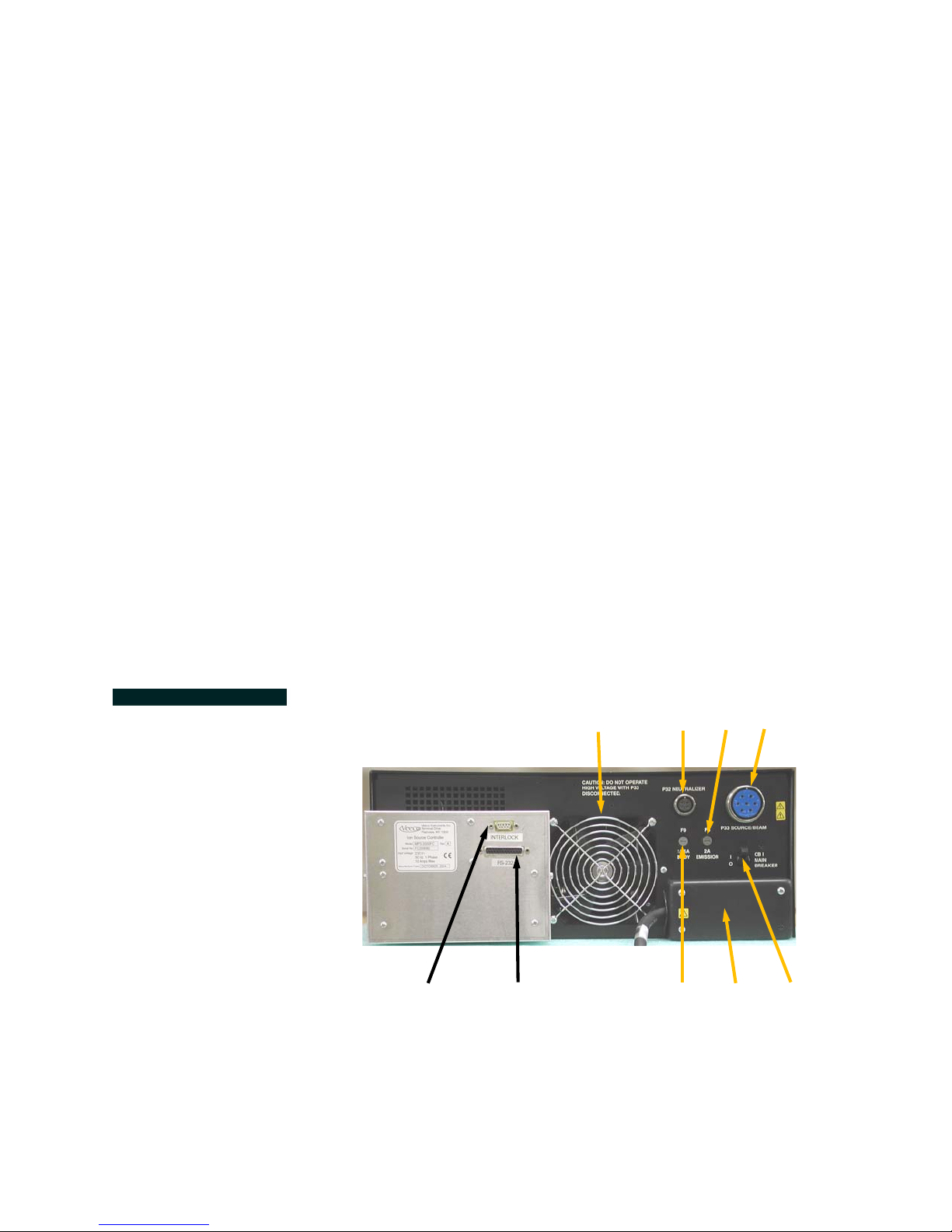
FIGURE 4.4 Rear
Panel: MPS-3000 CE
PBN Body Voltage Display (25)
Indicates the voltage difference between the body and filament on a PBN.
9
6
8
7
5
23
1
4
18
Page 23

Table 4.2: Power Supply Rear Panel
1Power Line Input
2 Source/Beam Connector (P33)
3 Neutralizer Connector (P32)
4 Circuit Breaker (CB1)
5Body Fuse (F9)
6 Cooling Fan
7 EIA-232 Interface Connector (DB25)
8Interlock Connector (DB9)
9 Emission Fuse (F8)
Power Input (1)
The cable provides power attachment between the power supply and the
facility mains.
Source/Beam Connector (P33) (2)
Output connector for the Cathode, Discharge, Beam, and Accelerator
power supplies and the source cable.
Neutralizer Connector (P32) (3)
Output connector for the Neutralizer power supply and the neutralizer
cable.
Circuit Breaker (CB1) (4)
Primary circuit breaker for the input power.
Body Fuse (F9) (5)
This fuse protects circuitry from positive high-voltage-to-ground shorts.
Cooling Fan (6)
Circulates air through the entire chassis of the power supply.
EIA-232 (RS-232) Interface Connector (DB25) (7)
Connector for interfacing with an external computer.
19
Page 24

Interlock Connector (DB9) (8)
Output cable connection of the external interlock circuit.
Emission Fuse (F8) (9)
Protects the neutralizer emission circuitry.
Controller Board Switch Definitions
The power supply is designed to allow the user to select several different
operating options. The options are selected and programmed into the
power supply by the appropriate positioning of switches located on the
controller board. To change switch settings refer to “Replacing the
Switches” on page 68.
• The on position indicates that the switch is towards the top of
the board.
• The off position indicates that the switch is towards the bottom
of the board.
Switch Settings for Switch Bank #1
SW1-1:
For factory use only. Do not change the positions of this switch.
SW1-2, SW1-3:
Power supply identifier. Selects a number for identification of a power
supply through the computer. When more than one power supply is
part of a computer-controlled system, each power supply may be
assigned a different identification number.
ID # SW 1-2 SW 1-3
1OnOn
2OnOff
3OffOn
4OffOff
SW1-4:
Neutralizer Fault Switch
MPS-3000 CE FC
20
Page 25

On - In the on position, the Discharge power supply will turn on
NOTE
without a neutralizer filament current present. The purpose of this
switch is to allow operation of an ion source without a neutralizer
current. Request zero neutralizer filament current when the Neutralizer Fault Switch is in the on position.
Off - In the off position, the discharge, beam, and accelerator outputs will be held low until the neutralizer filament current is within
0.5A of the target value and the cathode current is greater than
0.75A. Start-up of the ion source will not be possible if the neutral-
izer filament is open; the outputs of all power supplies will be shutdown if the filament fails during ion source operation. When an
open filament is detected, an intermittent audio alarm will sound,
an E23 error message appears on the Neutralizer Filament Current
display, and all other displays will be dark. The SOURCE and
BEAM switches will be inoperative until the neutralizer fault has
been corrected and the power has been cycled.
MPS-3000 CE HC and PBN
On - In the on position, the entire neutralizer supply is kept off.
Off - In the off position, the requested emission current is compared to the beam current. In Local, Local Restricted, or Remote
mode, the emission current will automatically track the beam current, with the emission being 125% or 200% of the beam current. If
the emission current is below 100% of the beam current, an E24
error message appears on the HCN Emission/Heater display, an
audio alarm will sound (if enabled), and the BEAM switch will be
turned off.
SW1-5, SW1-6:
Selects the baud rate. Baud rate represents the speed that the power
supply will communicate to an external computer through an EIA-232
interface.
Baud Rate SW 1- 5 SW 1- 6
9600 On Off
4800 Off On
2400 On On
1200 Off Off
The baud rate is factory preset to 9600 bps.
SW1-7:
Selects the emission-current-to-beam-current ratio in Local or Remote
mode.
21
Page 26

On - In the on position, the emission current will track the beam cur-
NOTE
NOTE
rent at 200%.
Off - In the off position, the emission current will track the beam current
at 125%.
SW1-8:
On - In the on position, the front panel will remain locked following a
power cycle if it was locked with the serial communication command
NK1.
Off - In the off position. The front panel will be unlocked following a
power cycle.
Table 4.3: Factory Switch Settings For Switch Bank #1
SW1SW2SW3SW4SW5SW6SW7SW8
Off Off Off Off On Off Off Off
All switches will be factory-set. The SW1-1 switch is for factory use only and
should never be changed.
Switch Settings for Switch Bank #2
SW2-1:
Not used.
SW2-2:
Controller Board Alarm Switch
On - In the on position, the controller board alarm will sound when a
Fatal error has been detected and will sound at power-up of the unit.
Off - In the off position, the controller board alarm will not sound when
a Fatal error has been detected or at unit power-up.
Table 4.4: Factory Switch Settings For Switch Bank #2
SW1 SW2
Off On
All switches will be factory-set. The SW1-1 switch is for factory use only
should never be changed.
22
Page 27

Chapter 5: Manual Operation
NOTE
MPS-3000 CE FC
Before beginning FC power supply operation, check the following:
• The appropriate ion beam source has been properly installed
in the vacuum system.
-2
• The vacuum system pressure is 4 x 10
lower.
• Sufficient gas flow is being introduced into the ion beam
source for appropriate operation.
Refer to the ion source’s technical manual for installation and operation
information.
FC Start-up
Pa (3 x 10⁻⁴ Torr) or
1. the facility mains breaker and Turn the unit’s POWER switch (on the
power supply front) to the on position.
a. The fan will start.
b. Random displays will appear, and the audio alarm will sound. This
condition will last about one second.
The controller will self-test each of the power supplies (from right to
left). A power supply has been tested when the letter P appears in
the top display.
c. A click will be heard when the main contactor energizes after about
six seconds.
d. The unit is ready to operate an ion source after each power supply
has been tested.
2. Follow these steps to operate the power supply in Manual Mode:
a. Turn the KEYLOCK switch to the Mode Enable position.
b. Select Manual using the MODE switch. The word MANUAL
appears above the switch indicating that Manual mode has been
selected.
c. To lock the power supply in Manual mode, turn the KEYLOCK
switch to the disable position and remove the key.
3. Use the MEMORY switch to select the memory location the unit will use
to store parameters; the selected memory location will appear.
23
Page 28

4. Select the discharge voltage. For initial start-up and training purposes,
NOTE
select 55V.
a. Select the Discharge power supply with the MODULE switch. The
letters DISCHARG appear above the switch.
b. Select Voltage with the FUNCTION switch. The word VOLTAGE
appears above the switch.
c. Enter the value by turning the Adjust knob. The programmed value
appears on the Discharge Voltage display.
d. As the Adjust knob is turned, the discharge voltage is entered auto-
matically into the selected memory.
5. Select the discharge current limit. For initial start-up and training purposes, select 1.00A.
a. Select the Discharge power supply with the MODULE switch on the
front panel. The letters DISCHARG appear above the switch.
b. Select Limit with the FUNCTION switch. The word LIMIT appears
above the switch.
c. Enter the chosen value by turning the Adjust knob. The pro-
grammed value appears on the Discharge Current display.
d. As the Adjust knob is turned, the discharge current limit is entered
automatically into the selected memory.
6. Select the cathode filament current limit.
Refer to the “Tables” on page 83 for current limits for various ion
sources.
a. Select the Cathode power supply with the MODULE switch. The
word CATHODE appears above the switch.
b. Select Limit with the FUNCTION switch. The word LIMIT appears
above the switch.
c. Adjust the current limit up or down as needed. The value appears
on the Cathode Filament Current display.
Different sizes and types of filament wire may require adjustments to the
cathode filament current limit. Unless the source size is known, the cathode
current limit will be factory-set at 6.5A.
d. The final selected value is stored automatically in the memory, as
indicated above the MEMORY switch.
24
Page 29

7. Select the cathode filament current.
NOTE
NOTE
Refer to the “Tables” on page 83 for initial filament currents for various
ion sources.
The current values assume that 0.25mm (0.010 in.) tungsten wire is used
for the cathode filament. If the actual filament is a different size and/or
material, other filament currents could be required.
a. Select the Cathode power supply with the MODULE switch and
Current with the FUNCTION switch. The words CATHODE and
CURRENT appear above the appropriate switches.
b. Select the chosen value by turning the Adjust knob. The new value
appears on the Cathode Filament Current display.
c. As the Adjust knob is turned, the cathode filament current is entered
automatically into the selected memory.
8. Select the neutralizer filament current limit.
Refer to the “Tables” on page 83 for current limits for various ion
sources.
a. Select the neutralizer power supply with the MODULE switch. The
word NEUTRALIZER appears above the switch.
b. Select Limit with the FUNCTION switch. The word LIMIT appears
above the switch.
c. Adjust the current limit upwards or downwards as needed. The
value appears on the Neutralizer Filament Current display.
Different sizes and different types of filament wire may require adjustments
to the neutralizer filament current limit. Neutralizer current limit will be factory-set at 6.5A.
d. The final selected value is stored automatically in the memory, as
indicated above the MEMORY switch.
9. Select the neutralizer filament current.
Refer to the “Tables” on page 83 for initial filament currents for various
ion sources.
a. Select the neutralizer power supply with the MODULE switch and
current with the FUNCTION switch. The words NEUT and CURRENT appear above the appropriate switches.
b. Enter the chosen value by turning the Adjust knob. The value will
appear on the Neutralizer Filament Current display.
c. As the Adjust knob is turned, the neutralizer filament current is
entered automatically into the selected memory location.
25
Page 30

10. Apply power to the source.
WARNING
NOTE
NOTE
To avoid electrical shock, keep clear of “live” circuits.
Refer to the “Tables” on page 83 for current limits for various ion
sources.
a. Press the SOURCE ON/OFF switch. The word SOURCE appears
above the switch.
•When the SOURCE switch is activated, several changes will be
observable on the front panel:
• The cathode filament current will increase from 0.0 to the
programmed value.
• The neutralizer filament current will increase from 0.0 to the
programmed value.
• When the neutralizer current is within 0.5A of the selected target, and the cathode current is greater than 0.75A, the discharge voltage will increase to about 150V.
• As the source discharge starts, the discharge current will
increase and the discharge voltage will decrease to the programmed value.
b. Increase the cathode current, if necessary.
1.) Select the Cathode power supply with the MODULE switch and
Current with the FUNCTION switch.
2.) Turn the Adjust knob clockwise until the discharge stabilizes or
until the recommended cathode current limit is reached.
When the current limit has been reached, cathode current may not be
increased.
If the discharge has not started before the recommended current
limit is reached:
1.) Reduce the cathode current.
2.) Select Cathode with the MODULE switch.
3.) Select Current with the FUNCTION switch.
4.) Turn the Adjust knob counterclockwise until the cathode current
reaches the original selected value.
If the discharge does not start (i.e., no discharge current) or is unstable,
and the discharge voltage oscillates between the approximate programmed value and 150V, insufficient cathode current or insufficient gas
flow could be the cause.
26
Page 31

c. Increase the gas flow to the ion beam source by about 1sccm and
NOTE
WARNING
repeat Step 10.
• If necessary, repeat Steps a. and b. until either a flow rate of
10sccm or a chamber pressure of 6.7 x 10
-2
Pa (5 x 10⁻⁴ Torr)
is reached.
• If the discharge still will not start, refer to the “Troubleshooting/
Error Code Definitions” on page 69 and to the ion source
technical manual.
11. Select the beam voltage. For initial start-up purposes, use a value of
1000V.
a. Select the Beam power supply with the MODULE switch. Voltage
will automatically be selected in the Manual mode. The words
BEAM and VOLTAGE appear above the appropriate switches.
b. Enter the chosen voltage by turning the Adjust knob. The changing
values appear on the Beam Voltage display.
c. As the Adjust knob is turned, the beam voltage is entered automat-
ically into the selected memory.
12. Set the A/B Ratio.
The recommended and factory-set A/B Ratio is 10% for all sources.
a. Select the Accelerator power supply with the MODULE switch. The
letters ACCEL appear above the switch.
b. Select the A/B Ratio with the FUNCTION switch. The letters A/B
appear above the switch.
c. With the Adjust knob, select the accelerator-current-to-beam-cur-
rent ratio. The A/B Ratio appears on the Accelerator Voltage display.
d. The final selected ratio is stored automatically in the memory, as
indicated above the MEMORY switch.
13. Select the accelerator voltage. For initial start-up purposes, use a value
of 250V.
a. Select the Accelerator power supply with the MODULE switch and
Voltage with the FUNCTION switch. The words ACCEL and VOLTAGE appear above the appropriate switches.
b. Enter the voltage by turning the Adjust knob. The changing value
will appear on the Accelerator Voltage display.
c. As the Adjust knob is turned, the accelerator voltage is entered
automatically into the selected memory.
14. Start the ion beam.
To avoid electrical shock, keep clear of “live” circuits.
27
Page 32

15. Press the BEAM ON/OFF switch. The word BEAM appears above the
NOTE
NOTE
switch.
• A beam current value should appear on the Beam Current display.
• An accelerator current value should appear on the Accelerator
Current display.
The actual current values depend on other parameters, such as source size,
cathode filament current request, gas flow, and beam and accelerator voltage requests.
16. The ion source should operate and extract an ion beam.
FC Adjustment
Follow these steps to adjust the system to the chosen operating conditions.
1. Adjust the beam current.
a. Select the beam voltage (refer to Step 11. on page 27).
b. Adjust the discharge voltage to the chosen level (refer to Step 4. on
page 24). When operating with argon, the recommended voltage
is 55V.
CAUTION
c. Adjust the cathode current to obtain the chosen beam current (refer
to Step 6. on page 24).
If the chosen beam current requires an increase in cathode filament current, carefully monitor this filament current to ensure that it does not exceed
the recommended values of 6.5A for 5cm or smaller sources.
If the chosen beam current is obtainable, (i.e., within specified performance limits) but not reachable without exceeding the recommended
maximum filament current, increase the discharge voltage and/or gas
flow.
• If the discharge voltage is less than 55V, increase the value to
acquire the beam current.
• If the beam current is not acquired with a 55V discharge
request and a maximum recommended filament current,
increase the gas flow.
Avoid system pressures in excess of 6.7 x 10
increases arcing within and around the ion source.
Special circumstances may require operation with the discharge voltage and/or system pressures in excess of the recommended values.
While operating at these conditions is possible, reduced source operating efficiency and lifetime may be experienced.
-2
Pa (5 x 10⁻⁴ Torr). This
28
Page 33

Do not select beam current while in Manual mode.
NOTE
NOTE
CAUTION
2. Adjust for a minimum accelerator current:
a. Adjust the accelerator voltage to minimize the accelerator current
(refer to Step 13. on page 39). Typically, the accelerator current
should be no more than 10% of the beam current.
• Excessive accelerator currents may be an indication of misaligned grids or a system pressure above 4 x 10
To rr) .
• Refer to the ion source technical manual for grid alignment
procedures.
b. Adjust the operating conditions and/or gas flow rate to bring the A/
B Ratio within the recommended limits.
When the accelerator-current-to-beam-current ratio exceeds the programmed A/B Ratio value, an audio alarm will sound, if enabled, and an
E25 error message will appear on the Accelerator Current display.
Operating the ion source with high accelerator current may damage the
grids.
-2
Pa (3 x 10⁻⁴
3. Adjust the neutralizer filament current until the neutralizer emission current is about 110% to125% of the beam current (refer to Step 9. on
page 25).
• When the neutralizer current is satisfactory, the MPS-3000 CE
FC power supply should be completely adjusted for Manual
mode operation.
• The user may continue operating in Manual mode or may
select Local mode (refer to “Local Operation” on page 42).
FC Storing Operating Conditions
All adjustable operating conditions are stored automatically in the selected
memory location when the Adjust knob is turned. This is the only method of
storing parameters.
FC Recalling Operating Conditions
Selecting RCL with the MEMORY switch, allows the user to view the operating conditions stored in the unused memory location. After about four seconds, the original parameters will be displayed.
29
Page 34

MPS-3000 CE HC
NOTE
Before beginning HC power supply operation, check the following:
• The appropriate ion beam source has been properly installed
in the vacuum system.
-2
• The vacuum system pressure is 4 x 10
Pa (3 x 10⁻⁴ Torr) or
lower.
• Sufficient gas flow is introduced into the ion beam source,
internal HC, and internal HCN for appropriate operation.
Refer to the ion source’s technical manual for installation and operation
information.
HC Start-up
1. Turn the facility mains breaker and the unit’s POWER switch (on the
power supply front) to the on position.
a. The fan will start.
b. Random displays will appear, and the audio alarm will sound. This
condition will last about one second.
• The controller will self-test each of the power supplies (from
right to left). A power supply has been tested when the letter P
appears in the top display.
c. A click will be heard when the main contactor energizes after about
six seconds.
d. The unit is ready to operate an ion source after each power supply
has been tested.
2. Follow these steps to operate the power supply in Manual mode.
a. Turn the KEYLOCK switch to the Mode Enable position.
b. Select Manual using the MODE switch. The word MANUAL
appears above the switch indicating that Manual mode has been
selected.
c. To lock the power supply in Manual mode, turn the KEYLOCK
switch to the disable position and remove the key.
3. Use the MEMORY switch to select the memory location the power supply will use to store parameters; the selected memory location will
appear above the switch.
30
Page 35

4. Select the discharge current limit. For initial start-up and training pur-
NOTE
NOTE
NOTE
poses, select 1.00A.
Refer to “Recommended Discharge Current Limits” on page 83 for
suggested discharge current limits for different source sizes.
a. Select the Discharge power supply with the MODULE switch. The
letters DISCHARG appear above the switch.
b. Select Limit with the FUNCTION switch. The word LIMIT appears
above the switch.
c. Adjust the current limit up or down as needed. The value appears
on the Discharge Current display.
Unless the source size is known, discharge current limit will be factory-set at
2.00A.
d. The final selected value is stored automatically in the memory, as
indicated above the MEMORY switch.
5. Select the discharge current. For initial start-up and training purposes,
select 1.00A.
a. Select the discharge supply with the MODULE switch and current
with the FUNCTION switch. The words DISCHARG and CURRENT
appear above the appropriate switches.
b. Enter the chosen value by turning the Adjust knob. The pro-
grammed value appears on the Discharge Current display.
c. As the Adjust knob is turned, the discharge current is entered auto-
matically into the selected memory.
6. Select the hollow cathode keeper voltage limit.
The recommended and factory-set keeper voltage limit is 25V.
a. Select the Hollow Cathode power supply with the MODULE switch.
The letters HC appear above the switch.
• Limit will be selected automatically and the word LIMIT
appears above the FUNCTION switch.
b. Adjust the keeper voltage limit up or down as needed. The value
will appear on the Hollow Cathode Keeper Voltage display.
c. The final selected value is stored automatically in the memory, as
indicated above the MEMORY switch.
7. Select the hollow cathode neutralizer keeper voltage limit.
The recommended and factory-set keeper voltage limit is 25V.
a. Select the Hollow Cathode Neutralizer power supply with the
MODULE switch. The letters HCN appear above the switch.
31
Page 36

b. Select Limit with the FUNCTION switch. The word LIMIT appears
WARNING
above the switch.
c. Adjust the keeper voltage limit up or down as needed. The value
appears on the Hollow Cathode Neutralizer Keeper Voltage display.
d. The final selected value is stored automatically in the memory, as
indicated above the MEMORY switch.
8. Select the hollow cathode neutralizer emission current.
Emission current may be selected before the internal HCN starts, but no
current will be provided by the Hollow Cathode Neutralizer power supply until the internal HCN starts and the keeper voltage is below the
keeper voltage limit.
a. Select the Hollow Cathode Neutralizer power supply with the
MODULE switch and Current with the FUNCTION switch. The
words HCN and CURRENT appear above the appropriate switches.
b. Enter the chosen value by turning the Adjust knob. The value
appears on the Hollow Cathode Neutralizer Emission Current display.
c. As the Adjust knob is turned, the emission current is entered auto-
matically into the selected memory location.
9. Apply power to the source.
To avoid electrical shock, keep clear of “live” circuits.
a. Press the SOURCE ON/OFF switch. The word SOURCE appears
above the switch. When the SOURCE switch is activated, several
changes may be observed on the front panel:
• The hollow cathode heater current will ramp to 7.25A.
• The hollow cathode neutralizer heater current will ramp to
7.25A. Select HCN with the MODULE switch and HEATER with
the FUNCTION switch to view the heater current.
• When the source discharge starts, the discharge current will
increase to the programmed value, and the discharge voltage
will decrease.
• When the internal hollow cathode starts, the keeper voltage
will drop below 25V, and the heater current will decrease to
3.75A.
• When the internal hollow cathode neutralizer starts, the keeper
voltage will drop below 25V, and the heater current will
decrease to 3.75A.
• The emission current will increase to the programmed value
after the keeper voltage drops below the keeper voltage limit.
32
Page 37

10. Select the beam voltage. For initial start-up purposes, use a value of
NOTE
WARNING
NOTE
1000V.
a. Select the Beam power supply with the MODULE switch. Voltage
will automatically be selected in the Manual mode. The words
BEAM and VOLTAGE appear above the appropriate switches.
b. Enter the chosen voltage by turning the Adjust knob. The changing
values appears on the Beam Voltage display.
c. The beam voltage is entered automatically into the selected mem-
ory as the Adjust knob is turned.
11. Set the A/B Ratio.
The recommended and factory-set A/B Ratio is 10% for all sources.
a. Select the Accelerator power supply with the MODULE switch. The
letters ACCEL appear above the switch.
b. Select the A/B Ratio with the FUNCTION switch. The letters A/B
appear above the switch.
c. Select the accelerator-current-to-beam-current ratio using the
Adjust knob. This ratio appears on the Accelerator Voltage display.
d. The final selected A/B Ratio is stored automatically in the memory,
as indicated above the MEMORY switch.
12. Select the accelerator voltage. For initial start-up purposes, use a value
of 250V.
a. Select the Accelerator power supply with the MODULE switch and
Voltage with the FUNCTION switch. The words ACCEL and VOLTAGE appear above the appropriate switches.
b. Enter the chosen voltage by turning the Adjust knob. The changing
value appears on the Accelerator Voltage display.
c. The accelerator voltage is entered automatically into the selected
memory as the Adjust knob is turned.
13. Start the ion beam.
To avoid electrical shock, keep clear of “live” circuits.
a. Press the BEAM ON/OFF switch. The word BEAM appears above
the switch.
• A beam current value appears on the Beam Current display.
• An accelerator current value should appear on the Accelerator
Current display.
Actual current values depend on other parameters, such as source size, gas
flow, and beam and accelerator voltage requests.
b. The ion source should operate and extract an ion beam.
33
Page 38

HC Adjustment
NOTE
NOTE
Follow these steps to adjust the system to the chosen operating conditions.
1. Adjust the beam current.
a. Select the beam voltage (refer to Step 10. on page 33).
b. Adjust the discharge current to obtain the chosen beam current
(refer to Step 5. on page 31).
Do not select beam current while in Manual mode.
2. Adjust for a minimum accelerator current.
a. Adjust the accelerator voltage to minimize the accelerator current
(refer to Step 12. on page 33). Typically, the accelerator current
should be no more than 10% of the beam current.
• Excessive accelerator currents may be an indication of misaligned grids or a system pressure above 4 x 10
To rr) .
• Refer to the ion source technical manual for grid alignment
procedures.
-2
Pa (3 x 10⁻⁴
CAUTION
b. Adjust the operating conditions and/or gas flow rate to bring the
A/B Ratio within the recommended limits.
When the accelerator-current-to-beam-current ratio exceeds the programmed A/B Ratio value, an audio alarm will sound, if enabled, and an
E25 error message will appear on the Accelerator Current display.
Operating the ion source with high accelerator current may damage the
grids.
3. Adjust the hollow cathode neutralizer emission current until the emission current is about 100% to 125% of the beam current (refer to Step
8. on page 32).
• When the neutralizer current is satisfactory, the MPS-3000 CE
HC should be completely adjusted for Manual mode operation.
• The user may continue operating in Manual mode or may
select Local mode (refer to “Local Operation” on page 42).
HC Storing Operating Conditions
All adjustable operating conditions are stored automatically in the selected
memory location when the Adjust knob is turned. This is the only method of
storing parameters.
34
Page 39

HC Recalling Operating Conditions
NOTE
Selecting RCL with the MEMORY switch allows the user to view the operating conditions stored in the unused memory location. After about four seconds, the original parameters will be displayed.
MPS-3000 CE PBN
Before beginning PBN power supply operation, check the following:
• The ion beam source has been properly installed in the vacuum system.
• The vacuum system pressure is 4 x 10
-2
Pa (3 x 10⁻⁴ Torr) or
lower.
• Sufficient gas flow introduced into the ion beam source and
internal PBN for appropriate operation.
Refer to the ion source’s technical manual for installation and operation
information.
PBN Start-up
1. Turn the facility mains breaker and the unit’s POWER switch (on the
power supply front) to the on position.
a. The fan will start.
b. Random displays will appear, and the audio alarm will sound. This
condition lasts about one second.
• The controller will self-test each of the power supplies (from
right to left). The letter P on the top display indicates a tested
power supply.
c. A click will be heard when the main contactor energizes after about
six seconds.
d. The unit is ready to operate an ion source after each power supply
has been tested.
2. Follow these steps to operate the power supply in Manual mode.
a. Turn the KEYLOCK switch to the Mode Enable position.
b. Select Manual using the MODE switch. The word MANUAL
appears above the switch when Manual mode has been selected.
c. To lock the power supply in Manual mode, turn the KEYLOCK
switch to the disable position and remove the key.
35
Page 40

3. Use the MEMORY switch to select the memory location the power sup-
NOTE
ply will use to store parameters; the selected memory location appears
above the switch.
4. Select the discharge voltage. For initial start-up and training purposes,
select 55V.
a. Select the Discharge power supply with the MODULE switch on the
front panel. The word DISCHARGE appears above the switch.
b. Select Voltage with the FUNCTION switch and the word VOLTAGE
appears above the switch.
c. Enter the chosen value by turning the Adjust knob. The value
appears on the Discharge Voltage display.
d. The discharge voltage is entered automatically into the selected
memory as the Adjust knob is turned.
5. Select the discharge current limit. For initial start-up and training purposes, select 1.00A.
a. Select the Discharge power supply with the MODULE switch on the
front panel. The word DISCHARG appears above the switch.
b. Select Limit with the FUNCTION switch. The word LIMIT appears
above the switch.
c. Enter the chosen value by turning the Adjust knob. The pro-
grammed value appears on the Discharge Current display.
d. The discharge current limit is entered automatically into the
selected memory as the Adjust knob is turned.
6. Select the cathode filament current limit.
Refer to the “Tables” on page 83 for current limits for various ion
sources.
a. Select the Cathode power supply with the MODULE switch. The
word CATHODE appears above the switch.
b. Select Limit with the FUNCTION switch. The word LIMIT appears
above the switch.
c. Adjust the current limit up or down as needed. The value appears
on the Cathode Filament Current display.
Different sizes and different types of filament wire may require adjustments
to the cathode filament current limit. Unless the source size is known, the
cathode current limit will be factory-set at 6.5A.
d. The final selected value is stored automatically in the memory, as
indicated above the MEMORY switch.
36
Page 41

7. Select the cathode filament current.
NOTE
NOTE
Refer to the “Tables” on page 83 for initial filament currents for various
ion sources.
The current values assume that 0.25mm (0.010 in.) tungsten wire is used
for the cathode filament. If the actual filament is a different size and/or
material, other filament currents could be required.
a. Select the Cathode power supply with the MODULE switch and
Current with the FUNCTION switch. The words CATHODE and
CURRENT appear above the appropriate switches.
b. Select the chosen value by turning the Adjust knob. The new value
appears on the Cathode Filament Current display.
c. The cathode filament current is entered automatically into the
selected memory as the Adjust knob is turned.
8. Select the PBN filament current limit.
Refer to the “Tables” on page 83 for current limits for various ion
sources.
a. Select the PBN power supply with the MODULE switch. The letters
PBN appear above the switch.
b. Select Limit with the FUNCTION switch. The word LIMIT appears
above the switch.
c. Adjust the current limit up or down as needed. The value appears
on the PBN Emission/Filament Current display.
Different sizes and different types of filament wire may require adjustments
to the PBN filament current limit, which is factory-set at 6.5A.
d. The final selected value is stored automatically in the memory, as
indicated above the MEMORY switch.
9. Select the PBN emission current.
a. Select an emission current that will be greater than the expected
beam current.
b. Select the PBN power supply with the MODULE switch and Current
with the FUNCTION switch. The words PBN and CURRENT appear
above the appropriate switches.
c. Enter the chosen value by turning the Adjust knob. The value
appears on the PBN Emission/Filament Current display.
d. The PBN emission current is entered automatically into the selected
memory location as the Adjust knob is turned.
37
Page 42

10. Apply power to the source.
WARNING
NOTE
NOTE
NOTE
To avoid electrical shock, keep clear of “live” circuits.
Refer to the “Tables” on page 83 for current limits for various ion
sources.
a. Press the SOURCE ON/OFF switch. The word SOURCE appears
above the switch.
b. When the SOURCE switch is activated, several changes are
observed on the front panel:
• The cathode filament current will increase from 0.0 to the programmed value.
• The PBN filament current increases until the body voltage has
dropped to between 20V and 25V.
The PBN filament current will not increase beyond the limit.
• When the cathode current is greater than 0.75A, the discharge
voltage will increase to about 150V.
• As the source discharge starts, the discharge current will
increase and the discharge voltage will decrease to the programmed value.
c. Increase the cathode current, if necessary.
1.) Select the cathode power supply with the MODULE switch and
current with the FUNCTION switch.
2.) Turn the Adjust knob clockwise until the discharge stabilizes or
until the recommended cathode current limit is reached.
When the current limit has been reached, cathode current may not be
increased.
If the discharge has not started before the recommended current
limit is reached:
1.) Reduce the cathode current.
2.) Select Cathode with the MODULE switch.
3.) Select Current with the FUNCTION switch.
4.) Turn the Adjust knob counterclockwise until the cathode current
reaches the original selected value.
If the discharge does not start (i.e., no discharge current) or is unstable,
and the discharge voltage oscillates between the approximate programmed value and 150V, insufficient cathode current or insufficient gas
flow could be the cause.
38
Page 43

d. Increase the gas flow to the ion beam source by about 1sccm and
NOTE
WARNING
repeat Step c.
• If necessary, repeat Steps c. through d. until a flow rate of
10sccm or a chamber pressure of 6.7 x 10
-2
Pa (5 x 10⁻⁴ To r r )
is reached.
• If the discharge still will not start, refer to the “Troubleshooting/
Error Code Definitions” on page 69 and to the ion source
technical manual.
11. Select the beam voltage. For initial start-up purposes, use a value of
1000V.
a. Select the beam power supply with the MODULE switch. Voltage
will automatically be selected in the Manual mode. The words
BEAM and VOLTAGE appear above the appropriate switches.
b. Enter the chosen voltage by turning the Adjust knob. The changing
values appears on the Beam Voltage display.
c. The beam voltage is entered automatically into the selected mem-
ory as the Adjust knob is turned.
12. Set the A/B Ratio.
The recommended and factory-set A/B Ratio is 10% for all sources.
a. Select the Accelerator power supply with the MODULE switch. The
letters ACCEL appear above the switch.
b. Select the A/B Ratio with the FUNCTION switch. The letters A/B
appear above the switch.
c. Use the Adjust knob to select the accelerator-current-to-beam-cur-
rent ratio. The A/B Ratio will appear in the Accelerator Voltage display.
d. The final selected ratio is stored automatically in the memory, as
indicated above the MEMORY switch.
13. Select the accelerator voltage. For initial start-up purposes, use a value
of 250V.
a. Select the Accelerator power supply with the MODULE switch and
Voltage with the FUNCTION switch. The words ACCEL and VOLTAGE appear above the appropriate switches.
b. Enter the chosen voltage by turning the Adjust knob. The changing
value appears on the Accelerator Voltage display.
c. The accelerator voltage is entered automatically into the selected
memory as the Adjust knob is turned.
14. Start the ion beam.
To avoid electrical shock, keep clear of “live” circuits.
39
Page 44

a. Press the BEAM ON/OFF switch. The word BEAM appears above
NOTE
NOTE
the switch.
• A beam current value should appear on the Beam Current display.
• An accelerator current value should appear on the Accelerator
Current display.
Actual current values depend on other parameters, such as source size,
cathode filament current request, gas flow, and beam and accelerator voltage requests.
b. The ion source should operate and extract an ion beam.
PBN Adjustment
Follow these steps to adjust the system to the chosen operating conditions.
1. Adjust the beam current.
a. Select the chosen beam voltage (refer to Step 11. on page 39).
b. Adjust the discharge voltage the recommended voltage is 55V
(refer to Step 4. on page 36).
CAUTION
c. Adjust the cathode current to obtain the chosen beam current (refer
to Step 6. on page 36).
If the chosen beam current requires an increase in cathode filament current, carefully monitor this filament current to ensure it does not exceed the
recommended values of 6.5A for 5cm and smaller sources.
If the chosen beam current is available (i.e., within specified performance limits), but not reachable without exceeding the recommended
maximum filament current, increase the discharge voltage and/or gas
flow.
• If the discharge voltage is less than 55V, increase the value to
acquire the beam current.
• If the beam current is not acquired with a 55V discharge
request an a maximum recommended filament current,
increase the gas flow.
Avoid system pressures in excess of 6.7 x 10
arcing within and around the arc will occur.
Special circumstances may require operating with the discharge voltage
and/or system pressures in excess of the recommended values. While operating at these conditions is possible, reduced source operating efficiency
and lifetime may occur.
-2
Pa (5 x 10⁻⁴ Torr). Increased
40
Page 45

NOTE
NOTE
CAUTION
Do not select beam current while in Manual mode.
2. Adjust for a minimum accelerator current.
a. Adjust the accelerator voltage to minimize the accelerator current
(refer to Step 13. on page 39). Typically, the accelerator current
should be no more than 10% of the beam current.
• Excessive accelerator currents may be an indication of misaligned grids or a system pressure above 4 x 10
To rr) .
• Refer to the ion source technical manual for grid alignment
procedures.
b. The excessive accelerator current may be lowered by adjusting the
operating conditions and/or gas flow rate to bring the A/B Ratio
within recommended limits.
When the accelerator-current-to-beam-current ratio exceeds the programmed A/B Ratio value, an audio alarm will sound, if enabled. An E25
error message will appear on the Accelerator Current display.
Operating the ion source with a high accelerator current could damage the
grids.
-2
Pa (3 x 10⁻⁴
3. Adjust the neutralizer emission current until the value is about 100% to
125% of the beam current (refer to Step 9. on page 37).
• When the PBN emission current is satisfactory, the MPS-3000
CE PBN should be completely adjusted for Manual mode
operation.
• The user may continue operating in Manual mode or may
select Local mode (refer to “Local Operation” on page 42).
PBN Storing Operating Conditions
All adjustable operating conditions are stored automatically in the selected
memory location when the Adjust knob is turned and is the only method of
storing parameters.
PBN Recalling Operating Conditions
Selecting RCL with the MEMORY switch allows the user to view the operating conditions stored in the unused memory location. After about four seconds, the original parameters will be displayed.
41
Page 46

Chapter 6: Local Operation
Operating conditions may need to be maintained over time without user
attention. The MPS-3000 CE power supply incorporates a Local or Automatic mode of operation. The internal microprocessor monitors and controls several parameters including the accelerator-current-to-beam-current
ratio (A/B Ratio).
If the value exceeds the limit programmed into the A/B Ratio, an E25 error
message appears on the Accelerator Current display and a continuous
audio signal will be heard if the audio alarm is enabled.
MPS-3000 CE FC:
In Local mode, the internal microprocessor constantly monitors the
beam current and maintains it at the programmed value by making
adjustments to the cathode filament current. The microprocessor also
monitors the neutralizer emission current and adjusts the neutralizer
supply as required to keep the emission-current-to-beam-current ratio
at 125%. A 200% emission-to-beam-current ratio may be selected
through SW1-7 (refer to “Controller Board Switch Definitions” on
page 20).
MPS-3000 CE HC:
In Local mode, the internal microprocessor constantly monitors the
beam current and maintains it at the programmed value by making
adjustments to the discharge current. The microprocessor also monitors
the hollow cathode neutralizer emission current to keep the emissioncurrent-to-beam-current ratio at 125%. A 200% emission-to-beamcurrent ratio may be selected through SW1-7 (refer to “Controller
Board Switch Definitions” on page 20).
MPS-3000 CE PBN:
In Local mode, the internal microprocessor constantly monitors the
beam current and maintains it at the programmed value by making
adjustments to the cathode filament current. The microprocessor also
monitors the plasma bridge neutralizer emission current and keeps the
emission-to-beam- current ratio at 125%. A 200% emission-to-beamcurrent ratio may be selected through SW1-7 (refer to “Controller
Board Switch Definitions” on page 20).
In Local mode, stored values may be recalled from the memories. Use
the switches and Adjust knob on the front panel to make changes in
beam voltage, beam current, accelerator voltage, and A/B Ratio. No
changes may be made for any parameters in Cathode, HC, Discharge,
Neutralizer or HCN power supplies.
42
Page 47

To avoid electrical shock, keep clear of “live” circuits. Follow all local lock-
WARNING
NOTE
out/tag out procedures before continuing.
Follow these steps for operation in Local mode:
1. Turn the facility mains breaker and the unit’s POWER switch (on the
power supply front) to the on position.
2. Wait for completion of the self-test procedure.
3. Select Local mode with the MODE switch. The word LOCAL appears
above the switch.
4. Select the chosen memory with the MEMORY switch. The parameters
stored in the selected memory location appears and may be verified on
the front panels.
5. The chamber pressure and ion source gas flow rate must be adequate
for the requested conditions.
6. Press the SOURCE switch. The word SOURCE appears above the
switch.
Consider the age of the filament when recalling values from memory. An
older filament does not require as much current as a new filament to start
or function.
MPS-3000 CE FC
The cathode filament current will ramp to the programmed value.
The neutralizer filament current will ramp to the value from memory.
• When the neutralizer filament current is within 0.5A of the target current, and the cathode filament current is greater than
0.75A, the discharge voltage will rise to about 150V. As the
ion source discharge starts, a discharge current appears and
the discharge voltage will ramp to the value from memory.
MPS-3000 CE HC
The hollow cathode heater current will ramp to 7.25A.
• When the internal hollow cathode has started, the heater current will ramp down to 3.75A, and the keeper voltage should
drop below 25V.
The hollow cathode neutralizer heater current will ramp to 7.25A.
• When the internal hollow cathode neutralizer has started, the
heater current will ramp down to 3.75A, and the keeper voltage should drop below 25V. The emission current will increase
to the programmed value after the keeper voltage drops below
the keeper voltage limit.
43
Page 48

• In Local mode, the emission current must be greater than the
NOTE
beam current to prevent an E24 error condition.
MPS-3000 CE PBN
The cathode filament current will ramp to the programmed value.
The plasma bridge neutralizer filament current will ramp up until the
body voltage drops to between 20 and 25V or until the filament current
limit is reached.
• Once the body voltage is between 20 and 25V, the emission
current will increase to the programmed value.
• In Local mode, the emission current must be greater than the
beam current to prevent an E24 error condition.
7. Wait for the discharge voltage and/or current to stabilize.
8. Press the BEAM switch. The word BEAM should appear above the
MODULE switch.
9. The beam current, beam voltage, and accelerator voltage should ramp
to their programmed values.
When changing from Manual to Local mode, the displayed beam current
in Manual mode will become the new beam current target for Local mode.
This value will be stored in the memory locations used.
10. Change the memory locations.
a. Operating conditions that are stored in the unused memory loca-
tion may be viewed by selecting RCL with the MEMORY switch.
b. Use the MEMORY switch to change to other memory locations. The
power supply will ramp to the new parameters as soon as the memory location is changed.
44
Page 49

Chapter 7: Other Modes of Operation
Local Restricted
This mode of operation is limited to conditions recalled from memory. The
user may not change any parameter, and the Adjust knob is nonfunctional.
All switches are active, except the MODULE and FUNCTION switches.
The Local Restricted mode of operation is useful when limited user intervention is needed. Parameters must be stored in the memory locations in
advance.
1. Select the chosen operating conditions in Manual or Local mode.
2. Select the LOC RES mode with the MODE switch.
3. Turn the KEYLOCK switch to the disable position and remove the key.
4. The user may turn the SOURCE or BEAM switches on or off and change
from one memory location to another.
5. The MPS-3000 CE power supply will function as if it were in Local
mode.
Remote Operation
The MPS-3000 CE power supply must be controlled remotely, by a computer, through an EIA-232 interface.
The only front panel switches that are functional in the Remote mode are
the MODE, SOURCE, and BEAM OFF switches.
45
Page 50

Chapter 8: Serial Communications
NOTE
The EIA-232 interface standard1 (formerly known as RS-232C) establishes
electrical and mechanical interface requirements. It does not define the
exact function of all the signals that are used by the various manufacturers
of data communications equipment and serial I/O devices. Consequently,
when the serial interface is plugged into an EIA-232 connector, there is no
guarantee that the device may communicate unless the user has configured
certain parameters to match the computing device requirements. Refer to
the computing device’s technical manual for information on electrical and
mechanical interfacing, setting the interface format, and data transfer
range.
The following information for the MPS-3000 CE power supply will be
needed for successful connection and communication with the computing
device:
• serial communications rate - 9600 baud
The serial communications rate may be adjusted using switches SW1-5 and
SW1-6 on the controller board. Refer to “Controller Board Switch Defini-
tions” on page 20.
• other parameters - 1 start bit, 8 data bits, 2 stop bits, no parity.
Refer to Table 8.1: for detailed pin assignment.
Table 8.1: EIA-232 Pin Assignment
Pin No. Function
2Receive
3Transmit
7Ground
A maximum of ±25V DC is allowed for the EIA-232 port. Serial communications wiring should have a minimum insulation rating of 100V DC per
lead; these leads should be shielded, with a drain wire attached to a metallic connector shell. An insulating sheath covering the leads, shield and
drain wire shall have a minimum insulation rating of 300V DC.
1. EIA-232 is a data communication standard established by the Elec-
tronic Industries Association (EIA). The EU equivalent is CCITT V.24
46
Page 51

A command is executed when a carriage return <cr> is received. All characters are echoed by the unit. Two commands per second will be accepted;
commands received at a faster rate are placed in a 250 character buffer.
When this buffer is filled, additional characters will be lost.
The RS-232 communications is active in all modes. Refer to “Command
Summary Table” on page 48.
Responses:
Unless stated otherwise, all commands that are accepted will respond with:
<lf><cr>OK<lf><cr><eot>
If the command is not accepted, the response will be:
<lf><cr>?<lf><cr><eot>
47
Page 52

Command Summary Table
Table 8.2: Command Summary Table
Command Description
A Attention
AB Set A/B Ratio
AC Enable/Disable Auto Cathode Mode
AD Enable/Disable Auto Data Logging
AE Enable/Disable Auto Error Logging
B Turn Beam Supplies On/Off
BE Set Beam Current Tolerance
BI Set Beam Current
BV Set Beam Voltage
CI Set Cathode Current
CL Set Cathode Limit
DI Set Discharge Current
DL Set Discharge Current Limit
DT Set Discharge Current Threshold
DV Set Discharge Voltage
M Set Power Supply Mode
NE Enable/Disable E/B Ratio Error
NI Set Neutralizer Current
NK Enable/Disable Front Panel
NL Set Neutralizer Limit
R Recall Memory
RC Request Running Conditions, Condensed Format
RH Manual Data Log Request, no Header
RN Request Target Parameters, Condensed Format
RP Request Target Parameters
RS Manual Data Log Request
RST Reset power supply
S Turn Source Supplies On/Off
T Set Auto Data Logging Interval
V Request Power Supply Version
VI Request Power Supply Version, Condensed Format
48
Page 53

Detailed Command Description
Command Name: ATTENTION
Syntax: A<cr>
Units: N/A
Range: N/A
Description: This command places the power supply into Remote mode.
Command Name: SET ACCELERATOR TO BEAM CURRENT RATIO LIMIT
(A/B RATIO)
Syntax: AB[n]<cr>
Units: %
Range: n = 0 - 99
Description: This command sets the value for the accelerator current to
beam current ratio limit. If this limit is exceeded, an E25 error message
appears in the accelerator current display.
EXAMPLE 8.1 Set the
A/B Ratio Limit
Set the A/B Ratio limit to 15% using the following command: AB15<cr>
Command Name: AUTO CATHODE MODE
Syntax: AC[N]<cr>
Units: N/A
Range: n = 0 or 1
Description: This command enables (AC1) or disables (AC0) the Auto
Cathode (AC) mode, which is active only when the power supply is in
Remote mode. However, the command will be accepted in any mode.
MPS-3000 CE FC/PBN:
When the AC mode is active, the cathode filament current increases
automatically until the cathode filament current has reached its limit, or
the discharge current has exceeded the discharge current threshold.
MPS-3000 CE HC:
When the Auto Cathode mode is active, the minimum discharge current target is equal to the discharge current threshold. The value of the
AC command is stored in non-volatile RAM and stays in effect until it is
changed.
Disable the Auto Cathode mode using the following command: AC0<cr>
EXAMPLE 8.2 Disable
the Auto Cathode Mode
49
Page 54

EXAMPLE 8.3 Disable
Auto Data Logging
Command Name: AUTOMATIC DATA LOGGING
Syntax: AD[N]<cr>
Units: N/A
Range: n = 0 or 1
Description: This command is used to enable (AD1) or disable (AD0) automatic data logging.
When enabled, the power supply will transmit its actual running conditions at the time interval specified by the T<n> command.
Logging will begin when the source is turned on and will end when the
source is turned off.
Disable auto data logging using the following command: AD0<cr>
Command Name: AUTOMATIC ERROR LOGGING
Syntax: AE[n]<cr>
Units: N/A
Range: n = 0 or 1
EXAMPLE 8.4 Enable
Auto Error Logging
EXAMPLE 8.5 Set the
Accelerator Voltage
Description: This command is used to enable (AE1) or disable (AE0) automatic error logging.
When enabled, the power supply will transmit any error conditions that
occur while the source and beam are on.
Enable auto error logging using the following command: AE1<cr>
Command Name: SET ACCELERATOR VOLTAGE
Syntax: AV[n]<cr>
Units: volts
Range: n = 0 - 1023
Description: Sets the target value for the accelerator voltage. When the
beam is on, the accelerator voltage will ramp to this value.
Set the accelerator voltage to 400V using the following command:
AV400<cr>
50
Page 55

EXAMPLE 8.6 Turn
the Beam Supply On
Command Name: BEAM ON/OFF
Syntax: B[n]<cr>
Units: N/S
Range: n = 1 or 0
Description: Used to turn the beam supply on (B1) or off (B0).
Turn the beam supply on using the following command: B1<cr>
Command Name: SET BEAM CURRENT TOLERANCE LIMIT
Syntax: BE[n]<cr>
Units: %
Range: n = 0 - 99
Description: Sets the beam current tolerance limit. When the beam is on
and the power supply is not in Manual mode, check that the beam current
remains within the specified limit.
If it is out of tolerance for more than one second, the beam will be
turned off and an E13 error message will appear in the beam current
display.
EXAMPLE 8.7 Set the
Beam Current Tolerance Limit
EXAMPLE 8.8 Set the
Beam Current
To disable this feature, send the following command to the power supply BE0<cr>.
Set the beam current tolerance limit to 5% using the following command:
BE5<cr>
Command Name: SET BEAM CURRENT
Syntax: BI[n]<cr>
Units: mA
Range: n = 0 - 300
Description: Sets the target value for the beam current. When the beam is
on and the power supply is not in Manual mode, the beam current will
ramp to this value.
Set the beam current to 200mA using the following command: BI200<cr>
51
Page 56

EXAMPLE 8.9 Set the
Beam Voltage
Command Name: SET BEAM VOLTAGE
Syntax: BV[n]<cr>
Units: volts
Range: n = 0 - 1200
Description: Sets the target value for the beam voltage. When the beam is
on, the beam voltage will ramp to this value.
Set the beam voltage to 1000V using the following command:
BV1000<cr>
Command Name: SET CATHODE CURRENT
Syntax: CI[n]<cr>
Units: MPS-3000 CE FC/PBN: amperes
MPS-3000 CE HC: N/A
Range: MPS-3000 CE FC/PBN: 0.00 - 20.00
MPS-3000 CE HC: N/A
Description:
EXAMPLE 8.10 Set
the Cathode Filament
Current Target
MPS-3000 CE FC and PBN:
Used to set the cathode filament current target. The filament current will
ramp to this value when the power supply is in Manual mode. In all
other modes, this command has no effect, but is still accepted. The
command will not be accepted if the entered value is greater than the
cathode current limit.
MPS-3000 CE HC:
Command is not valid.
Set the MPS-3000 CE FC/PBN cathode filament current target to 4.50A
using the following command: CI4.50<cr>
52
Page 57

EXAMPLE 8.11 Set the
Cathode Filament Limit
EXAMPLE 8.12 Set the
Keeper Voltage Limit
Command Name: SET CATHODE LIMIT
Syntax: CL[n]<cr>
Units: MPS-3000 CE FC/PBN: amperes
MPS-3000 CE HC: volts
Range: MPS-3000 CE FC/PBN: 0.00 - 20.00
MPS-3000 CE HC: 0 - 50
Description:
MPS-3000 CE FC and PBN:
Used to set the cathode filament current’s software limit. The actual filament current will not ramp above this value.
MPS-3000 CE HC:
Used to set the hollow cathode keeper voltage limit.
Set the MPS-3000 CE FC/PBN cathode filament limit to 5.50A using the
following command: CL5.50<cr>
Set the MPS-3000 CE HC hollow cathode keeper voltage limit to 25V
using the following command: CL25<cr>
EXAMPLE 8.13 Set the
Discharge Current
Command Name: SET DISCHARGE CURRENT
Syntax: DI[n]<cr>
Units: amperes
Range: n = 0.00 - 6.00
Description: Sets the target value for the discharge current. When the
source is on and in Manual mode, the discharge current will ramp to this
value.
This command is effective only in Manual mode, but is accepted in all
modes and is only valid for an MPS-3000 CE HC power supply.
Set the discharge current to 2.00A using the following command:
DI2.00<cr>
53
Page 58

EXAMPLE 8.14 Set the
Discharge Current
Limit
Command Name: SET DISCHARGE CURRENT LIMIT
Syntax: DL[n]<cr>
Units: amperes
Range: n = 0.00 - 6.00 (MUST BE IN THE FORM n.nn)
Description: Sets the discharge current limit value. This discharge current
will not be allowed to ramp above this value.
MPS-3000 CE FC OR PBN:
The cathode current will ramp down if this value is exceeded. An E02
error message will appear in the discharge current display.
MPS-3000 CE HC:
The discharge current target will not be allowed to be greater than this
value.
Set the discharge current limit to 2.00A using the following command:
DI2.00<cr>
Command Name: SET DISCHARGE CURRENT THRESHOLD
EXAMPLE 8.15 Set the
Discharge Current
Threshold
EXAMPLE 8.16 Set the
Discharge Current
Voltage
Syntax: DT[n]<cr>
Units: amperes
Range: n = 0.00 - 6.00 (MUST BE IN THE FORM n.nn)
Description: Sets the discharge current threshold value. Refer to the auto
cathode command for a description of the discharge current threshold.
Set the discharge current threshold to 0.05A using the following command:
DT0.05<cr>
Command Name: SET DISCHARGE VOLTAGE
Syntax: DV[n]<cr>
Units: volts
Range: n = 0 - 150.0
Description: Sets the target value for the discharge voltage. When the
source is on, this is the value the discharge voltage will ramp to.
This command is only valid for an MPS-3000 CE FC power supply.
Set the discharge voltage to 55.0V using the following command:
DV55.0<cr>
54
Page 59

EXAMPLE 8.17 Place
the MPS-3000 power
supply in Local mode
Command Name: SET MODE
Syntax: M[n]<cr>
Units: N/A
Range: n = 0, 1, 2, or 3
Description: Used to set the operating mode of the power supply.
nMode
0Manual
1Local
2Local Restricted
3Remote
Place the power supply in Local mode using the following command:
M1<cr>
Command Name: DISABLE E/B RATIO ERROR
Syntax: NE[n]<cr>
EXAMPLE 8.18 Disable
the E/B Ratio Error
Units: N/A
Range: n = 0 or 1
Description:
When disabled (NE1), the E/B Ratio error (E24) will not be activated if
the emission current drops below the beam current. In all modes
(except Manual mode), the emission current will still automatically
servo to 125% of the beam current.
When enabled (NE0), the E/B Ratio error will function normally.
The value of the NE command is stored in non-volatile RAM and stays in
effect until it is changed.
Disable the E/B Ratio error using the following command: NE1<cr>
55
Page 60

Command Name: SET NEUTRALIZER CURRENT
Syntax: NI[n]<cr>
Units: MPS-3000 CE FC: amperes
MPS-3000 CE PBN: mA
MPS-3000 CE HCN: mA
Range: MPS-3000 CE FC: 0.00 - 15.00
MPS-3000 CE PBN: 0 - 600
MPS-3000 CE HCN: 0 - 600
Description:
MPS-3000 CE FC:
Used to set the neutralizer filament current target. The filament current
will ramp to this value when the MPS-3000 CE FC power supply is in
Manual mode. In all other modes, this command has no effect, but is
still accepted. The command will not be accepted if the entered value is
greater than the neutralizer current limit (NL[n]).
MPS-3000 HCN/PBN:
Used to set the emission current target. The emission current will ramp
to this value when the MPS-3000 CE HC/PBN power supply is in Manual mode. In all other modes, this command has no effect, but is still
accepted.
EXAMPLE 8.19 Set the
Neutralizer Filament
Current Target
EXAMPLE 8.20 Set
the Emission Current
Set the MPS-3000 CE FC neutralizer filament current target to 4.50A using
the following command: NI4.50<cr>
Set the MPS-3000 CE HCN/PBN emission current to 250mA using the following command: NI250<cr>
Command Name: LOCKOUT FRONT PANEL SWITCHES
Syntax: NK[n]<cr>
Units: N/A
Range: n = 0 or 1
Description:
When enabled (NK1), all of the switches on the power supply’s front
panel will not function. Also, the alarm will not sound on any fatal of
non-fatal error.
When disabled (NK0), all switches and the buzzer act normally. The
value of the NK command is stored in non-volatile RAM and stays in
effect until it is changed. If SW1-8 is in the off position, the front panel
will be unlocked following a power cycle. To maintain a lock on the
front panel, SW 1-8 should be set to the on position.
EXAMPLE 8.21 Front
Panel Switches Lockout
Lockout the front panel switches using the following command: NK1<cr>
56
Page 61

EXAMPLE 8.22 Set
the Neutralizer Limit
Command Name: SET NEUTRALIZER LIMIT
Syntax: NL[n]<cr>
Units: MPS-3000 CE FC: amperes
MPS-3000 CE PBN: amperes
MPS-3000 CE HCN: volts
Range: MPS-3000 CE FC: 0.00 - 15.00
MPS-3000 CE PBN: 0.00 - 10.23
MPS-3000 CE HCN: 0 - 50
Description:
MPS-3000 CE FC/PBN:
Used to set the neutralizer filament currents software limit. The actual
filament current will not ramp above this value.
MPS-3000 CE HC:
Used to set the HCN keeper voltage limit.
Set the MPS-3000 CE FC/PBN neutralizer limit to 5.50A using the following command: NL5.50<cr>
EXAMPLE 8.23 Set the
Keeper Voltage Limit
EXAMPLE 8.24 Recalling Memory 1
Set the MPS-3000 CE HCN keeper voltage limit to 25V using the following
command: NL25<cr>
Command Name: RECALL TARGETS FROM MEMORY
Syntax: R[n]<cr>
Units: N/A
Range: n = 1, 2
Description: Recalls the target parameters from the selected memory. The
recalled values will be the new running parameters.
Recall memory 1 using the following command: R1<cr>
57
Page 62

Command Name: REQUEST RUNNING CONDITIONS, COMPRESSED
FORMAT
Syntax: RC<cr>
Units: N/A
Range: N/A
Response:
<lf><cr>
AA.AA,BB.BB,CCC.C,^DDDD,^EEEE,^FFFF,^GGGG,^HHHH,II.II
,^JJJJ,^KKKK,^LLLL,M,
<lf><cr><eot>
Where:
Parameter Model Units
AA.AA
Cathode Current
HC Heater Current
MPS-3000 CE FC
MPS-3000 CE HC
Amps
Amps
BB>BB Discharge Current All Amps
CCC.C Discharge Voltage All Volts
DDDD Beam Current All mA
EEEE Beam Voltage All Volts
FFFF Accelerator Current All mA
GGGG Accelerator Voltage All Volts
HHHH Emission Current All mA
II.II
Neut Filament Current
HCN Heater Current
PBN Filament Current
MPS-3000 CE FC
MPS-3000 CE HCN
MPS-3000 CE PBN
Amps
Amps
Amps
JJJJ HC Keeper Voltage MPS-3000 CE HC Volts
KKKK HCN Keeper Voltage MPS-3000 CE HCN Volts
LLLL Fatal Error Code All N/A
M Power
Supply
Mode
0 = Manual
1 = Local
2 = Local Restricted
3 = Remote
= ACSII Blank Space (32)
All N/A
Description: Used to request the power supply’s running conditions. All of
the above parameters will be transmitted. If a value is off or not present for
that model, its value is replaced with ASCII blank spaces (32).
58
Page 63

Command Name: MANUAL DATA LOG REQUEST WITHOUT HEADER
Syntax: RH<c>
Units: N/A
Range: N/A
Response:
With the source and/or beam on:
<cr><lf>^^^^^^AA:BB:CC^^^DD.DD^^^E.EE^^^F
FF.F^^^
GGG^^^HHHH^^^IIII^^^JJJ^^^^^KKK^^LL.LL
<lf><cr><eot>
Where:
Parameter Model Units
Hours/
Minutes/
Seconds
Amps
Amps
AA.BB.CC
DD.DD
Time since source was
turned on
Cathode Filament Current
HC Heater Current
MPS-3000 CE FC
MPS-3000 CE HC
E.EE Discharge Current All Amps
FFF.F Discharge Voltage All mA
GGG Beam Current All mA
HHHH Beam Voltage All Volts
IIII Accelerator Current All Volts
JJJ Accelerator Current All mA
KKK Emission Current All mA
ll.ll
Neut Filament Current
HCN Heater Current
PBN Filament Current
MPS-3000 CE FC
MPS-3000 CE HC
MPS-3000 CE PBN
Amps
Amps
Amps
^ ACSII Blank Space (32)
With the source and beam off:
Where:
DDDD - Fatal error message. If there is no fatal error message when the RH
command is received, DDDD = Blank Space (32).
^ = ASCII BLANK SPACE (32)
Description: Used to request data logging parameters without header information. If a value is off, it will be replaced with ASCII blank spaces (32).
<lf><cr>^^^^^^^^^^^^^^^^^SOURCE^&^BE
AM^ARE^OFF^DDDD
<lf><cr><eot>
59
Page 64

Command Name: REQUEST TARGET PARAMETERS WITH HEADER
Syntax: RP[n]<cr>
Units: N/A
Range: n = 1, 2
Response:
MPS-3000 CE FC/PBN:
<lf><cr>MEM^1^PARAMETERS:
<lf><cr>BEAM^V^^^^BEAM^I^^^^ACCEL^V^^^^A
/B^RATIO
^^^^CATH^LIM^^^^NEUT^LIM^^^^DISCH^V
<lf><cr>XXXX^V^^^^XXX^mA^^^^XXXX^V^^^^^^
^^XX^%
^^^^^^XX.XX^A^^^^^XX.XX^A^^^^^XXX.X^V
<lf><cr><eot>
MPS-3000 CE HC:
<lf><cr>MEM^1^PARAMETERS:
<lf><cr>BEAM^V^^^^BEAM^I^^^^ACCEL^V^^^^A
/B^RATIO
EXAMPLE 8.25 Request
Target Parameters
^^^^CATH^LIM^^^^NEUT^LIM
<lf><cr>XXXX^V^^^^XXX^mA^^^^XXXX^V^^^^^^
^^XX^%
^^^^^^^^XXX^V^^^^^^^XXX^V
<lf><cr><eot>
^ = ASCII BLANK SPACE (32)
Description: This command is used to request the above target values, with
header information, for the selected memory.
Request the target parameters stored in Memory 2 using the following command: RP2<cr>
60
Page 65

Command Name: REQUEST ALL TARGET PARAMETERS IN COMPRESSED
FORMAT
Syntax: RN[n]<cr>
Units: N/A
Range: n = 1, 2
Response:
<lf><cr>^AAAA,^BBBB,^CCCC,^^^DD,EEEEE,FFFFF,GGGG
G,HHHHH,IIIII,JJJJJ,KKKKK,
<lf><cr><eot>
Where:
Parameters Model Units
AAAAA Beam Voltage All Volts
BBBBB Beam Current All mA
CCCCC Accelerator Voltage All Volts
DDDDD A/B Ratio All %
EXAMPLE 8.26 Request
all Target Parameters
EEEEE
Cathode Filament Limit
HC Keeper Voltage Limit
Neutralizer Filament Limit
FFFFF
HCN Keeper Voltage Limit
PBN Filament Limit
GGGGGDischarge Voltage
Discharge Current
MPS-3000 CE FC
MSP-3000 CE HC
MPS-3000 CE FC
MPS-3000 CE HCN
MPS-3000 CE PBN
MPS-3000 CE FC
MPS-3000 CE HC
Amps
Volts
Amps
Volts
Amps
Volts
Amps
HHHHH Beam Current Tolerance All %
IIIII Discharge Current Threshold All Amps
JJJJJ Cathode Filament Current MPS-3000 CE FC Amps
KKKKK
Neutralizer Filament
Current
Emission Current
MSP-3000 CE FC
MPS-3000 CE
HCN/PBN
Amps
mA
Description: Used to request all target values, in the compressed format,
from the selected memory. If the value is not reported for a particular
model, it is replaced with ASCII blank spaces (32).
Request all the target parameters stored in Memory 1 using the following
command: RN1<cr>
61
Page 66

Command Name: MANUAL DATA LOG REQUEST
Syntax: RS<cr>
Units: N/A
Range: N/A
Response:
If the source and/or beam are on:
<lf><cr>^^^^^^^^TIME^^^^^^^CI^^^^^DI
^^^^^DV^^^^^BI
^^^^^BV^^^^^AV^^^^^AI^^^^^EI^^^^^
NI
<lf><cr>^^^^^^HH:MM:SS^^^^AMPS^^^AMPS^^
^VOLTS
^^^mA^^^^VOLTS^^VOLTS^^^mA^^^^^mA^^
^^AMPS
<cr><lf>^^^^^^XX:XX:XX^^^XX.XX^^^X.XX^^^XXX.X
^^XXXX^^^XXXX^^^XXXX^^^XXX^^^^XXXX^^XX.XX
<lf><cr><eot>
If the source and beam are off:
<lf><cr>^^^^^^^^^^^^^^^^^SOURCE^&^BE
AM^ARE^OFF^DDDD
<lf><cr><eot>
Where:
DDDD - Fatal Error Message. If there is no fatal error message when the RS
command is received, DDDD = blank spaces (32).
^ = ASCII BLANK SPACE (32)
Description: This command is used to request data logging parameters. It is
only valid when automatic data logging is disabled.
Command Name: RESET MPS-3000 CE
Syntax: RST<cr>
Units: N/A
Range: N/A
Description: This command is used to reset the power supply.
62
Page 67

EXAMPLE 8.27 Turn
On the Source Supplies
Command Name: SOURCE ON/OFF
Syntax: S[n]<cr>
Units: N/A
Range: n = 1 or 0
Description: Used to turn the source supplies on (S1) or off (S0).
Turn the source supplies on using the following command: S1<cr>
Command Name: SET AUTOMATIC DATA LOG TIME INTERVAL
Syntax: T[n]<CR>
Units: N/A
Range: n = 0 - 9
Description: Used to set the time interval at which the power supply will
transmit data when automatic data logging is enabled.
T0 - 2 Second Interval
T1 - 10 Second Interval
EXAMPLE 8.28 Setting the Auto Data
Log Time Interval
T2 - 20 Second Interval
T3 - 30 Second Interval
T4 - 1 Minute Interval
T5 - 2 Minute Interval
T6 - 5 Minute Interval
T7 - 10 Minute Interval
T8 - 30 Minute Interval
T9 - 1 Hour Interval
Set the auto data log time interval to 1 minute using the following command: T4<cr>
63
Page 68

Command Name: REQUEST POWER SUPPLY TYPE
Syntax: V<cr>
Units: N/A
Range: N/A
Response: (Only one response will be transmitted.)
MPS-3000 CE FC:
<lf><cr>MPS-3000 FC #x<lf><cr><eot>
MPS-3000 CE HC:
<lf><cr>MPS-3000 HC #x<lf><cr><eot>
MPS-3000 CE PBN:
<lf><cr>MPS-3000 PBN #x<lf><cr><eot>
Where: x = ID NUMBER 1 - 4
Description: Used to request the type of power supply.
Command Name: REQUEST POWER SUPPLY MODEL & MODULE TYPES
Syntax: V1<cr>
Units: N/A
Range: N/A
Response:
<lf><cr>ABCDEF<lf><cr><eot>
Where:
A - Power Supply Model:1 = MPS-3000 CE
B - Cathode Type: 0 = FC1 = HC
C - Beam Type: 0 = NORMAL
D - Neutralizer Type: 0 = FN1 = HCN2 = PBN
E - Discharge Type: 0 = FC1 = HC
F - Accelerator Type: 0 = NORMAL
Description: Used to request the power supply model.
64
Page 69

Chapter 9: Maintenance
WARNING
General
There are no user serviceable parts inside, except fuses. Refer servicing to
qualified personnel at Veeco.
To avoid electrical shock, keep clear of “live” circuits. Follow all local lockout/tag-out procedures, before repairing components or replacing fuses.
Fuse List
MPS-3000 CE FC
Power Board
F1 Cathode 6A
F2 Discharge 5A
F3 Neutralizer 5A
F4 Beam 5A
F5 Accelerator 2A
F6 Power Input 2A, Slo-Blo
F7 Logic Supply 2A, Slo-Blo
Rear Panel
F8 Emission 2A
F9 Body 1/16A, Slo-Blo
MPS-3000 CE HC
Power Board
F1 Hollow Cathode 3A
F2 Discharge 5A
F3 Hollow Cathode Neutralizer 3A
F4 Beam 5A
F5 Accelerator 2A
F6 Power Input 2A, Slo-Blo
F7 Logic Supply 2A, Slo-Blo
Rear Panel
F8 Emission 2A
F9 Body 1/16A, Slo-Blo
65
Page 70

MPS-3000 CE PBN
WARNING
Power Board
F1 Cathode 6A
F2 Discharge 5A
F3 Plasma Bridge Neutralizer 5A
F4 Beam 5A
F5 Accelerator 2A
F6 Power Input 2A, Slo-Blo
F7 Logic Supply 2A, Slo-Blo
F12 PBN Body 1A Picofuse
Rear Panel
F8 Emission 2A
F9 Body 1/16A, Slo-Blo
A spare parts kit, containing extra fuses, is included with the power supply.
Use Veeco part number 6290-002 to reorder this spare parts kit.
Replacing the Fuses
To avoid electrical shock, keep clear of “live” circuits. Follow all local lockout/tag-out procedures, before replacing any power supply fuses.
Replace Fuse F1 through F7
1. Turn off the facility mains breaker and the CB-1 circuit breaker on the
power supply’s rear panel.
2. Remove the 26 screws holding the top cover and mounting ears to the
chassis.
3. Remove the top cover.
4. Locate the appropriate fuse holder.
5. Remove the fuse holder and fuse.
6. Replace the fuse (refer to “Fuse List” on page 65 for the correct rating
of the fuse).
7. Insert the fuse holder into the appropriate location.
8. Replace the top cover, mounting ears (if applicable), and screws.
9. Reconnect to power, and verify that the unit operates correctly. If the
problem persists, contact “Service Support” on page 73
66
Page 71

WARNING
CAUTION
Replace Fuse F8 or F9
1. Remove the correct fuse holder and fuse.
2. Replace the fuse (See “Fuse List” on page 65. for the correct rating).
3. Insert the fuse holder into the appropriate location on the rear panel.
Updating the Software
To avoid electrical shock, keep clear of “live” circuits. Follow all local lockout/tag-out procedures, before continuing.
To update software on the MPS-3000 CE power supply, a single PROM
must be changed. Updated PROM versions are sent in static-protected
bags.
Handle the PROM a static station to limit possible damage.
1. Turn off the facility mains breaker and the CB-1circuit breaker on the
power supply’s rear panel.
2. Remove the 26 screws holding the top cover and mounting ears to the
chassis.
3. Remove the top cover.
4. Replace the PROM located in the XU9 socket.
5. Use a small screwdriver to pry the PROM upward until loose.
6. Remove the PROM from the socket.
7. Orient the new PROM with the notched end toward the inside of the
controller board and insert it into the socket.
8. Apply equal pressure across the PROM until fully and evenly seated. All
the legs must enter straight into the socket and may need to be formed
before inserting the PROM.
9. Verify that the PROM is fully seated and all pins are in the socket.
10. Verify that the notch on the PROM is in the correct orientation.
11. Replace the top cover, mounting ears (if applicable), and screws.
12. Reconnect the power.
13. Verify that the power supply operates correctly.
• If the unit does not complete the self-test sequence, recheck
the seating and orientation of the PROM.
67
Page 72

• If the problem persists, contact “Service Support” on page 73
WARNING
NOTE
Replacing the Switches
To avoid electrical shock, keep clear of “live” circuits. Follow all local lockout/tag-out procedures, before continuing.
1. Turn off the facility mains breaker and the CB-1 circuit breaker on the
power supply’s rear panel.
2. Remove the 26 screws holding the top over and mounting ears to the
chassis.
3. Remove the top cover.
4. Locate SW1 and SW2 on the controller board.
5. Set the appropriate switch(es) to the chosen position.
6. Replace the top cover, mounting ears (if applicable), and screws.
7. Reconnect the power.
8. Verify that the power supply operates correctly.
• If a problem occurs, verify that all switches are in the appropriate position.
• If the problem persists, contact “Service Support” on page 73.
Returning an MPS-3000 CE Power Supply
1. Seal the power supply in a plastic bag.
2. Pack the unit using the original packing material and shipping box.
If the original packing material is not available, surround and cover the
power supply with foam and ship in a double-walled box.
3. Contact “Service Support” on page 73 before returning any equipment
to Veeco.
68
Page 73

69
Chapter 10: Troubleshooting/Error Code Definitions
To avoid electrical shock, keep clear of “live” circuits. Follow all local lock-out/ tag-out procedures, before repairing or replacing
any electrical devices. Disconnect the unit’s main power before replacing any fuse or troubleshooting any electrical connection.
Table 10.1: MPS-3000 CE Power Supply Troubleshooting
Problem Possible Cause Remedy
Front panel displays will not light,
fan will not start.
The power cord is not plugged in. Connect the power cord.
The unit’s CB1 circuit breaker on rear panel is tripped. Close circuit breaker on the unit’s rear panel.
The power plug is wired incorrectly. Correctly wire the power plug.
Front panel displays light. Fan
starts. An E20 error message
appears on all upper displays.
The external interlock string in not complete. Complete the interlock string.
An E22 error message appears on
the cathode module (MPS-3000
CE FC power supply only).
Open cathode filament. Replace the filament. See “Maintenance” on page 65.
Cable is not connected Connect the cable.
An E23 error message appears on
the neutralizer module (MPS-3000
CE FC/PBN power supply only).
Open neutralizer filament. Replace the filament. See “Maintenance” on page 65.
Cable is not connected. Connect the cable.
The ion source discharge will not
start.
The Body Fuse (F9) is open.
Replace the fuse with the correct value (refer to “Main-
tenance” on page 65), and check that the source body
is not grounded through cable connections or internal
connections.
Accelerator displays no current or a
very small current.
If the Accelerator output is shorted to the discharge output
(the anode) while the high voltage is on, damage to an
accelerator series resistor may result. When this occurs,
the Accelerator Current display will show zero current and
the Accelerator Voltage display will show the programmed
value. No accelerator voltage will be present at the source
connector (P33-F) on the unit’s rear panel.
Replace the resistor if damaged. Contact “Service Sup-
port” on page 73.
Power supply fails to retain stored
parameters in memory.
Battery is low.
Internal circuitry or a component is damaged.
Contact “Service Support” on page 73.
WARNING
Page 74

To avoid electrical shock, keep clear of “live” circuits. Follow all local lock-out/tag-out procedures before continuing. Disconnect the
controller’s main power before troubleshooting any electrical connection.
WARNING
70
Table 10.2: Error Code Definitions
Error
Code
Definition Probable Cause Suggested Remedy
E01
The keeper voltage has dropped below 100V
but has not dropped below the keeper voltage limit. Applies to both hollow cathode and
hollow cathode neutralizer power supplies.
Insufficient gas flow. Raise the gas flow.
The keeper voltage does not drop below the
keeper voltage limit (MPS-3000 CE HC unit).
The keeper voltage limit is set too low. Raise the keeper voltage limit.
E02
The discharge current has reached the programmed discharge current limit.
Insufficient gas flow. Raise the gas flow.
Discharge current limit set too low. Raise the limit.
E03
The operating value is low and is unable to
increase to meet the requested target.
Power into the power supply is low. Cycle the power.
A power supply fuse has failed.
Check the fuses on the Power Board.
Refer to “Maintenance” on page 65 for
fuse replacement.
Facility voltage is low. Raise facility voltage.
If the error message is on the neutralizer, the neutralizer
filament may be open (When SW1-4 is in the on position on the controller board, an open filament is not a
Fatal error).
Replace the neutralizer filament.
E04
The operating parameter is high and may not
be reduced to target value.
Requested target value is below operational limits. Increase the target value.
E05 Current Limit.
Requested target value is above the maximum current
capability of the power supply.
Reduce the requested target value.
The output is shorted.
Check the ion beam source and cable
connections (refer to the ion source
technical manual).
A power supply has failed.
Contact “Service Support” on page 73
to arrange for factory repair.
Page 75

To avoid electrical shock, keep clear of “live” circuits. Follow all local lock-out/tag-out procedures before continuing. Disconnect the
controller’s main power before troubleshooting any electrical connection.
WARNING
71
E06
Thermal shutdown.
Fatal error (refer to the NOTE on page 72).
Blockage of air flow.
Remove the blockage and cycle the
power.
Defective fan. Contact “Service Support” on page 73.
E07 Clock fault. Defective component. Contact “Service Support” on page 73.
E08
Cathode filament or neutralizer filament
error. This is a Fatal error (refer to the NOTE
on page 72). If a neutralizer filament is the
cause of this error, SW 1-4 is on (controller
board).
Broken cathode or neutralizer filament. Replace filament.
Cable is disconnected. Connect the cable.
E09
Only active if Auto Cathode (AC1 command). Cathode filament is at its limit and
the discharge current is less than the discharge current threshold (DT command).
Discharge threshold set is elevated (DT command). Decrease value.
Cathode limit set too low. Increase value.
Insufficient gas flow. Raise gas flow.
E13
Beam current is out of the tolerance set by
the BE command.
Insufficient gas flow. Raise the gas flow.
A large change in beam current was requested.
Disable E13 (BEO) before changing
beam current.
Cathode limit is set too low, 3000 CE FC or PBN only. Increase limit.
Discharge current set too low. Increase limit.
E18 HC shorted. various. Contact “Service Support” on page 73.
E19 HCN shorted. various. Contact “Service Support” on page 73.
E20 External interlock failure. External interlock circuit is incomplete. Complete the external interlock circuit.
E21
Internal interlock failure. Fatal error (refer to
the NOTE on page 72).
Voltage is low from the internal line conditioner. Cycle the power.
Facility voltage is low. Raise facility voltage.
Power plug is wired incorrectly. Rewire power plug.
E22
Cathode filament. Fatal error (refer to the
NOTE on page 72); MPS-3000 CE FC or
PBN power supplies only.
Broken cathode filament. Replace filament.
Cable is disconnected. Connect cable.
Table 10.2: Error Code Definitions (Continued)
Error
Code
Definition Probable Cause Suggested Remedy
Page 76
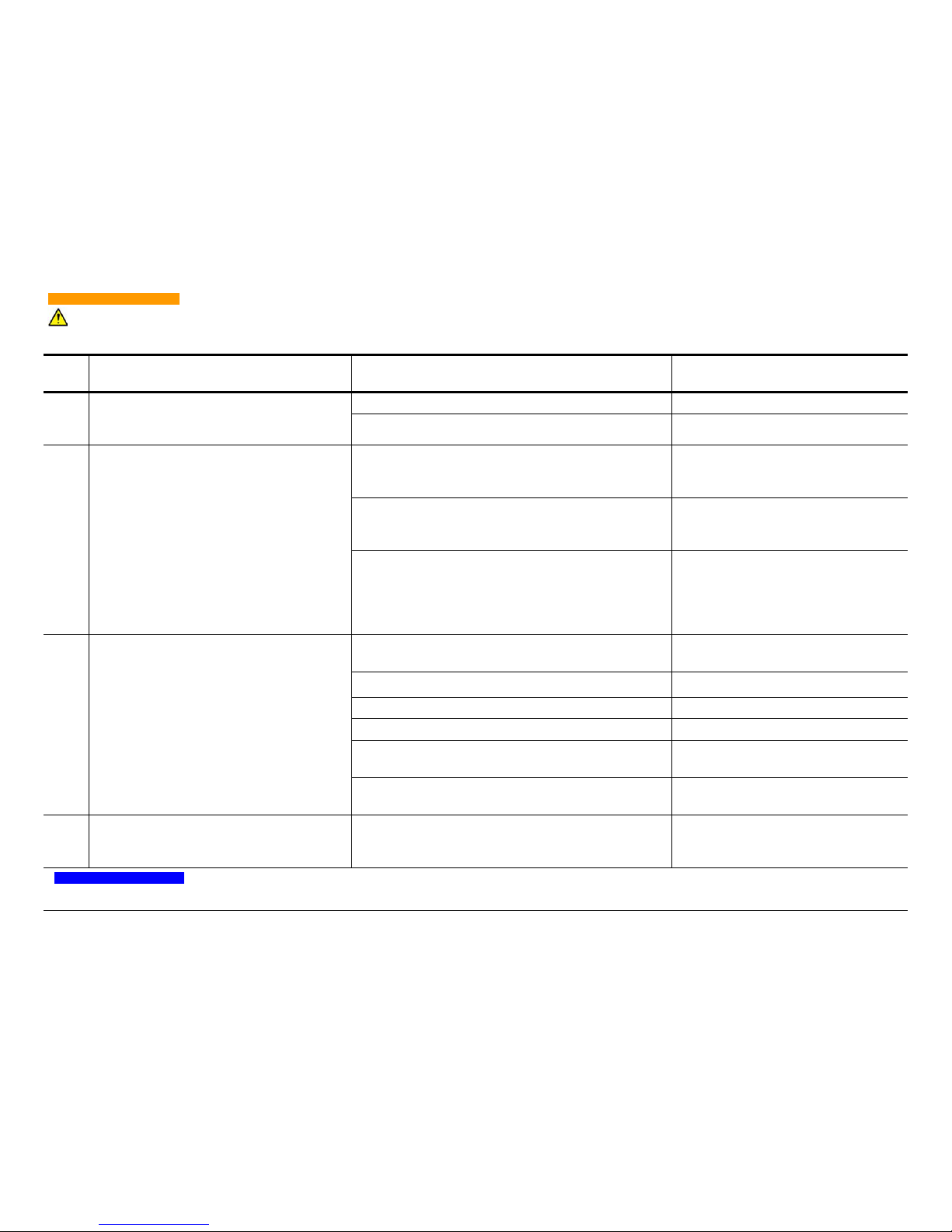
To avoid electrical shock, keep clear of “live” circuits. Follow all local lock-out/tag-out procedures before continuing. Disconnect the
controller’s main power before troubleshooting any electrical connection.
WARNING
72
E23
Neutralizer filament. SW 1-4 is on (controller
board); MPS-3000 CE FC or PBN units only.
Fatal error (refer to the NOTE below).
Broken neutralizer filament. Replace filament.
Cable is disconnected. Connect cable.
E24
Emission-current-to-beam-current ratio is less
than 100%. The error will occur only in Local,
Local Restricted, or Remote mode and only
when
SW 1-4 is off (controller board).
Low neutralizer filament current is causing the emission
current to be less than 100% of the beam current (filament neutralizer).
Go to Manual mode, and raise the filament current. Return to Local, Local
Restricted, or Remote mode.
Neutralizer filament current limit is set too low in Local,
Local Restricted, or Remote mode (flashes the LED on
the LIMIT switch). Filament neutralizer only.
Go to Manual mode to set current limit.
Return to Local, Local Restricted, or
Remote mode.
The emission current may not meet the programmed
value as a result of an impedance in cabling or in the
ion source (HCN & PBN only). A low impedance to
ground on the body is causing heavy current draw from
the beam power
Find and remove low impedance to
ground. Cycle the power.
E25
Accelerator-current-to-beam-current ratio
exceeds the programmed A/B Ratio.
Accelerator voltage is not set to minimize accelerator
current.
Adjust accelerator voltage.
System pressure exceeds 4 x 10
-2
Pa (3 x 1 0-4 Torr).
Reduce system pressure.
Excessive gas flow. Reduce gas flow.
Requested A/B Ratio is too low. Adjust A/B Ratio.
Extraction grids are misaligned.
Realign ion extraction grids (refer to the
ion source technical manual for details).
A low impedance is present between the extraction grids
(accompanied by an E05 error message on the beam).
Check the ion extraction grids for a low
impedance connection.
E26
Short to ground, external to the power supply.
Fatal error (refer to the NOTE below).
A low impedance is present between the source cathode
or hollow cathode and facility ground.
Remove the short to facility ground that
may exist at the source, feedthroughs, or
cables. Cycle the power.
A Fatal error will shut down the power supply until the problem is corrected. Power must be cycled (CB1 circuit breaker on the
unit’s rear panel or the facility mains switch).
Table 10.2: Error Code Definitions (Continued)
Error
Code
Definition Probable Cause Suggested Remedy
NOTE
Page 77

Chapter 11: Service Support
For service, contact:
Veeco Instruments Inc.
2330 East Prospect
Fort Collins, CO 80525
Phone: 1.888.221.1892
Fax: 970.493.1439
[email protected]
When contacting Veeco Instruments Inc. for parts or service:
Provide the ion source model number, serial number, and grid serial number. The model and serial number are engraved on the downstream surface
of the grid mount plate. The grid serial number is engraved on the
upstream surface of the grid.
Provide the ion source power supply model and serial number; a list of all
operating parameters and/or error messages displayed by the power supply; gas flow rate; and vacuum chamber pressure.
73
Page 78

Appendix A: Specifications
General
The MPS-3000 CE consists of a chassis containing these power supplies:
•beam voltage
• accelerator voltage
Each chassis contains one current supply from each of the following two
groups, depending on the end use:
1. cathode
• filament
• hollow (HC)
2. neutralizer
• filament
• hollow cathode (HCN)
• plasma bridge (PBN)
Each chassis also contains one of two discharge supply types, depending
on the end use:
•voltage (FC, PBN)
• current (HC)
The unit is designed for continuous operation. The power supply is CE
marked and its nameplate includes the following information:
Veeco Instruments Inc.
Terminal Drive
Plainview, NY 11803 USA
Product Name: Power Supply
Model:MPS3000LLL
Rev: L
Serial Number: LLNNNNNN
Input Voltage: 230V
50 Hz 1 Phase
10A Max
~
74
Page 79

Manufacture Date: Month -YYYY
CAUTION
NOTE
Manufactured for Veeco by:
TDP Inc.
4015 S. Lincoln
Loveland, CO 80537 USA
The Veeco CE representative in Europe is:
Vice President of International Sales and Marketing
Veeco Instruments S.A.
11, Rue Marie Poussepin
Zi De La Gaudree
91412 Dourdan, France
Mechanical
The power supply is designed to be mounted in a standard 19 inch equipment rack where the top, bottom, sides, and back are inaccessible while
powered on and operating.
Dimensions (height, width, and depth): 17.8 x 44.1 x 50.8cm
(7 x 17.38 x 20 in.)
Weight:18.4kg (40.5 lbs.)
It is recommended that two persons move each unit by grasping the unit’s
case.
To avoid back and other injuries, two persons should move each unit by
grasping the case.
Electrical
It is the user’s responsibility to meet all local and national electrical codes
when installing this equipment.
Input power to the unit should be 230V ~, phase to phase, 50Hz, with a
maximum actual current draw of 10A.
Standard 15A service may be used to supply power to the unit. The input
power should not fluctuate more than ±10% during operation. Although
the power cord contains a green ground wire, which must be connected to
75
Page 80

the power source’s ground, an additional 12 AWG safety ground wire with
WARNING
green/yellow colored insulation must also be connected between the
ground stud located on the rear of the unit and the power source’s safety
ground. The power cord feeding the unit must be permanently attached to
the power source.
All safety grounds must be attached before connecting power and removed
only after power is disconnected.
Since the unit’s MAIN “on/off” switch is located on the rear of the unit, a
separate external power disconnect switch must be provided. The System
Integrator or User must provide a suitably sized external overcurrent device
rated for not more than 16A.
The unit is a Class I grounded type equipment intended to be mounted in
an enclosed instrument rack, which only allows the front of the unit to be
accessible during operation. It also conforms to Installation Category II for
transient over voltage. The unit is equipped with a power switch on the
lower left front panel as well as a main switch on the rear of the unit. The
MAIN switch on the rear of the unit connects incoming power to the electronics inside the unit. The power switch on the front of the unit operates as
an ON/STANDBY switch and activates the electronics in the unit which then
supplies output power. These two switches are basically connected in series
so moving either of them to the off or standby position deactivates both the
cathode and anode outputs. Since the electrical outputs are deactivated,
the ion source process stops. The unit begins its initialization process and
delivering output when the switch is placed back in the on position.
Environmental
The unit is intended for indoor use only, requiring ordinary protection, and
is not protected against harmful ingress of moisture. The unit is designed
for Pollution Degree 2 ambient environment.
The unit is designed to operate in a relative humidity of 20 to 85% noncondensing and to be stored or transported in a relative humidity of 20 to
95% non-condensing.
The unit is designed to operate in an ambient temperature of 10 to 35°C
(50 to 95°F) and to be stored or transported in an ambient temperature
of -40 to 70°C (-40 to 158°F).
The unit is designed to operate at an altitude below 2,500m (8,200 ft.).
The unit is designed to operate in a laboratory environment that contains
minimal shock or vibration. When properly packaged in its factory supplied
shipping container, the unit will meet the transportation shock and vibration
requirements of the International Safe Transit Association (ISTA) specification, parts 2 and 2A.
76
Page 81

Power Output
NOTE
Some values may not be attainable due to individual source limitations.
MPS-3000 CE FC
Cathode Current Supply:
•0-20A AC
• 875W
• Programmable current limit.
• Sensing of open filament, causing shutdown of outputs.
•Soft start filament.
• Current limit protection.
• Filament current readout.
• Thermal protection.
Discharge Voltage Supply:
• 0-150V DC
• 300W, 6A maximum.
• Cathode open-filament interlock prevents discharge voltage
from rising when no cathode current is present.
• Over-voltage protection.
• Under no-load condition, output rises to 150V.
• Current limit protection.
• Voltage and current readouts.
• Thermal protection.
• Programmable current limit.
Beam Voltage Supply:
• 0-1200V DC
• 300mA maximum.
• 300W maximum.
• Current select for automatic operation.
• Over-voltage protection.
• Current limit protection.
• Accuracy ± 0.1% to 1000V.
• Voltage and current readouts.
• Thermal protection.
77
Page 82

Accelerator Voltage Supply:
• 0-1000V DC
• 30W maximum.
• 100mA maximum.
• Over-voltage protection.
• Current limit protection.
• Programmable accelerator-current-to-beam-current ratio limit.
• Voltage and current readouts.
• Thermal protection.
Neutralizer Current Supply:
•0-15A AC
• 450W
• Programmable current limit.
• Sensing of open filament, causing shutdown of outputs override on controller board.
•Soft start filament.
• Current limit protection.
• Filament current and emission current readouts.
• Thermal protection.
MPS-3000 CE HC
Hollow Cathode Current Supply:
• 0-7.25A AC heater supply.
• Programmable keeper voltage limit.
•Soft start.
• Current limit protection.
• Heater current readout.
• Keeper voltage readout.
• Thermal protection.
Discharge Current Supply:
• 0-150V DC
• 300W, 6A maximum.
• Programmable current limit.
78
Page 83

• Over-voltage protection.
• Under no-load condition, output rises to 150V.
• Current limit protection.
• Voltage and current readouts.
• Thermal protection.
Beam Voltage Supply:
• 0-1200V DC
• 300mA
• 300W maximum.
• Current select for automatic operation.
• Over-voltage protection.
• Current limit protection.
• Accuracy ± 0.1% to 1000V.
• Voltage and current readouts.
• Thermal protection.
Accelerator Voltage Supply:
• 0-1000V DC
• 30W maximum.
• 100mA maximum.
• Over voltage protection.
• Current limit protection.
• Programmable accelerator-current-to-beam-current ratio limit.
• Voltage and current readouts.
• Thermal protection.
Hollow Cathode Neutralizer Current Supply:
• 0-7.25A AC heater supply.
• 0-500mA DC emission current.
• Programmable keeper voltage limit.
•Soft start.
• Current limit protection.
• Heater current readout.
• Emission current and keeper voltage readouts.
• Thermal protection.
79
Page 84

MPS-3000 CE PBN
Cathode Current Supply:
•0-20A AC
• 875W
• Programmable current limit.
• Sensing of open filament, causing shutdown of outputs.
•Soft start filament.
• Current limit protection.
• Filament current readout.
• Thermal protection.
Discharge Voltage Supply:
• 0-150V DC
• 300W, 6A maximum.
• Cathode open-filament interlock prevents discharge voltage
from rising when no cathode current is present.
• Over-voltage protection.
• Under no-load condition, output rises to 150V.
• Current limit protection.
• Voltage and current readouts.
• Thermal protection.
• Programmable current limit.
Beam Voltage Supply:
• 0-1200V DC
• 300mA maximum.
• 300W maximum.
• Current select for automatic operation.
• Over-voltage protection.
• Current limit protection.
• Accuracy ± 0.1% to 1000V.
• Voltage and current readouts.
• Thermal protection.
Accelerator Voltage Supply:
• 0-1000V DC
• 30W maximum.
80
Page 85

• 100mA maximum.
• Over-voltage protection.
• Current limit protection.
• Programmable accelerator-current-to-beam-current ratio limit.
• Voltage and current readouts.
• Thermal protection.
Plasma Bridge Neutralizer Current Supply:
• 0-10A AC Filament Supply.
• 0-600mA DC Emission Supply.
• 200mA DC Body Supply.
• Programmable filament current limit.
•Soft start.
• Current limit protection.
• Filament current and emission current readouts.
• Body voltage readout.
• Thermal protection.
Programmed Limit Values
Table A.1: Programmed Limit Values
Parameter Default Value
Cathode Filament Current Limit
Set at 6.5A for 5cm or smaller
ion source
Hollow Cathode Keeper Voltage Limit Set at 25V
Neutralizer Filament Current Limit Set at 6.5V
Hollow Cathode Neutralizer Keeper
Voltage Limit
Set at 25V
A/B Ratio Limit 10%
Plasma Bridge Neutralizer Filament
Current Limit
6.5V
Discharge Current Limit 2.0A
The above limits are programmed into the power supplies at the factory.
The PBN filament current limit is set for tungsten wire, 0.25mm (0.010 in.),
but the preset A/B Ratio limit is the recommended value for operation of all
ion sources. Although the above are the recommended limits programmed
81
Page 86

into the power supply, the limits may be changed for operation of different
NOTE
sources or different filaments. New values will be stored along with the
operating parameters in one of the two nonvolatile memories. (Refer to “FC
Storing Operating Conditions” on page 29, “HC Storing Operating Conditions” on page 34, or “PBN Storing Operating Conditions” on page 41).
For the MPS-3000 CE power supply, the recommended cathode filament
limit (using 0.25mm/0.010 in. tungsten wire) for ion sources 5cm or
smaller is 6.5A. Check that both of the nonvolatile memories have the correct limit of 6.5A stored.
82
Page 87
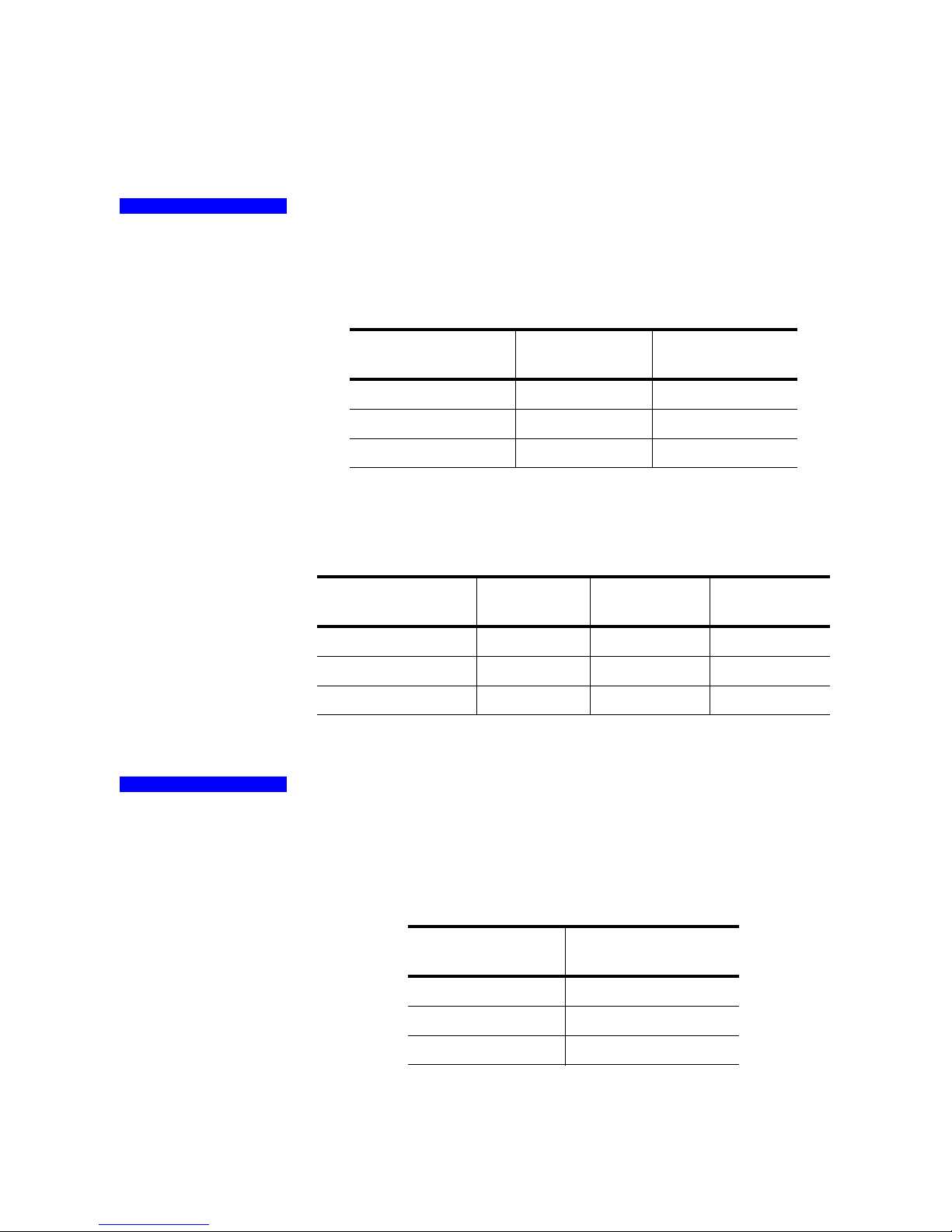
Appendix B: Tables
NOTE
NOTE
Initial filament current values apply for 0.25mm (0.010 in.) tungsten wire.
Recommended Initial Filament Current Limits
Table B.1: Circular Ion Source
Circular Ion Source
Size (in cm)
2.5 3.5A 3.5A
3 3.5A 3.5A
5 3.5A 3.5A
Recommended Current Filament Current Limits
Table B.2: Circular Ion Source
Circular Ion Source
Size (in cm)
2.5 6.5A 6.5A 6.5A
3 6.5A 6.5A 6.5A
5 6.5A 6.5A 6.5A
Discharge current limit is selectable only on the MPS-3000 CE HC power
supply.
Initial Cathode
Current
Cathode
Current Limit
Initial Neutralizer
Neutralizer
Current Limit
Current
PBN Current
Limit
Recommended Discharge Current Limits
Table B.3: Recommended Discharge Current Limits
Circular Ion Source
Size (in cm)
2.5 HP or LP 3.00A
3 2.50A
54.50
Discharge Current
Limit
83
Page 88

Appendix C: Environmental Safety
The equipment that you bought has required the extraction and use of natural resources for its production. It may contain hazardous substances that
could impact health and the environment. In order to avoid the dissemination of those substances in our environment and to diminish the pressure on
the natural resources, we encourage you to use the appropriate take-back
systems. Those systems will reuse or recycle most of the materials of your
end life equipment in a sound way.
The crossed-out wheeled bin symbol invites you to use those systems. If you
need more information on the collection, reuse and recycling systems,
please contact your local or regional waste administration. You can also
contact us for more information on the environmental performances of our
products.
84
Page 89

Appendix D: Drawings
One of the following drawings applies to your system:
“Filament Cathode with Filament Neutralizer or PBN Option”
“Hollow Cathode and HCN - 7 pin or 2 x 4 pin feedthrough”
“Hollow Cathode and Hollow Cathode Neut - 6 pin feedthrough”
“Filament Cathode with Filament Neutralizer or PBN Option”
“3cm Source Filament Cathode and Filament Neutralizer”
“3cm Source Hollow Cathode and Hollow Cathode Neutralizer”
“3cm Source Plasma Bridge Neutralizer”
85
Page 90

86
Filament Cathode with Filament Neutralizer or PBN Option
Page 91
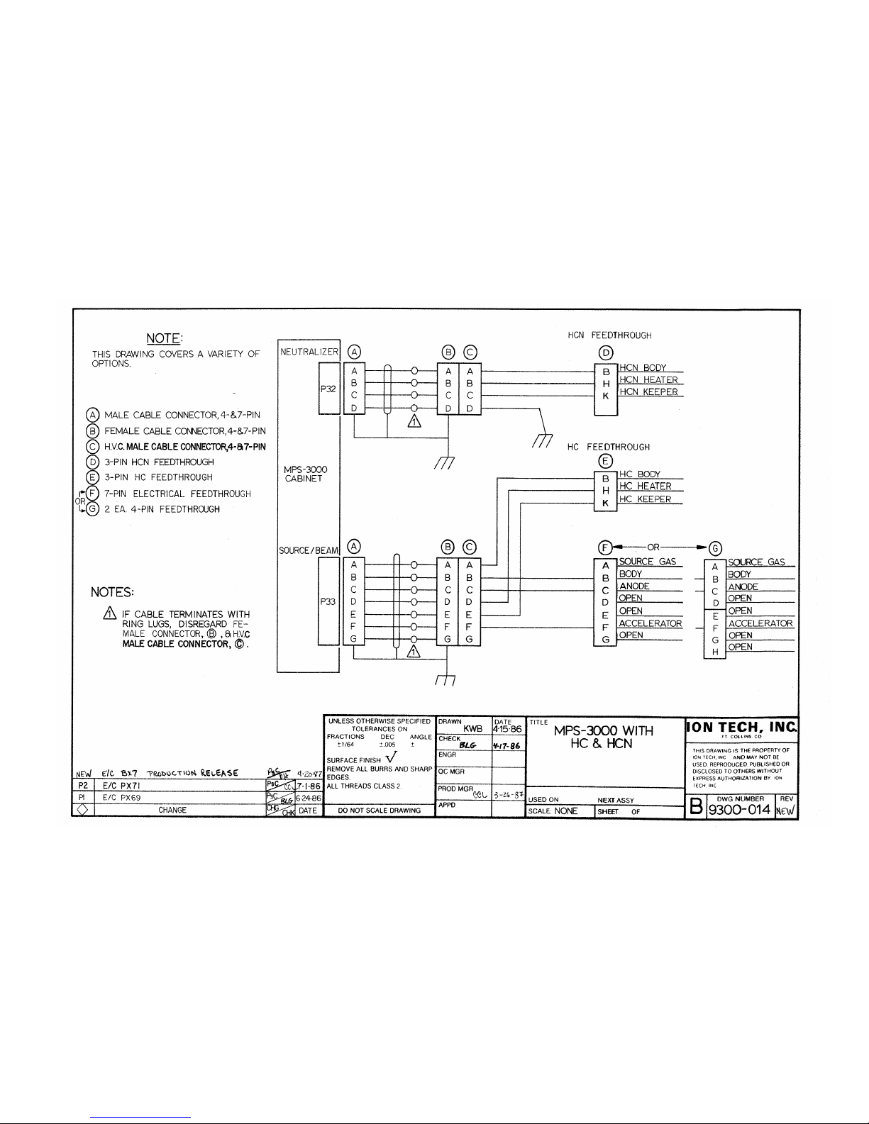
87
Hollow Cathode and HCN - 7 pin or 2 x 4 pin feedthrough
Page 92
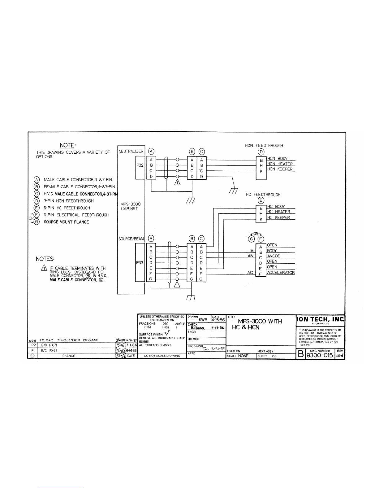
88
Hollow Cathode and Hollow Cathode Neut - 6 pin feedthrough
Page 93
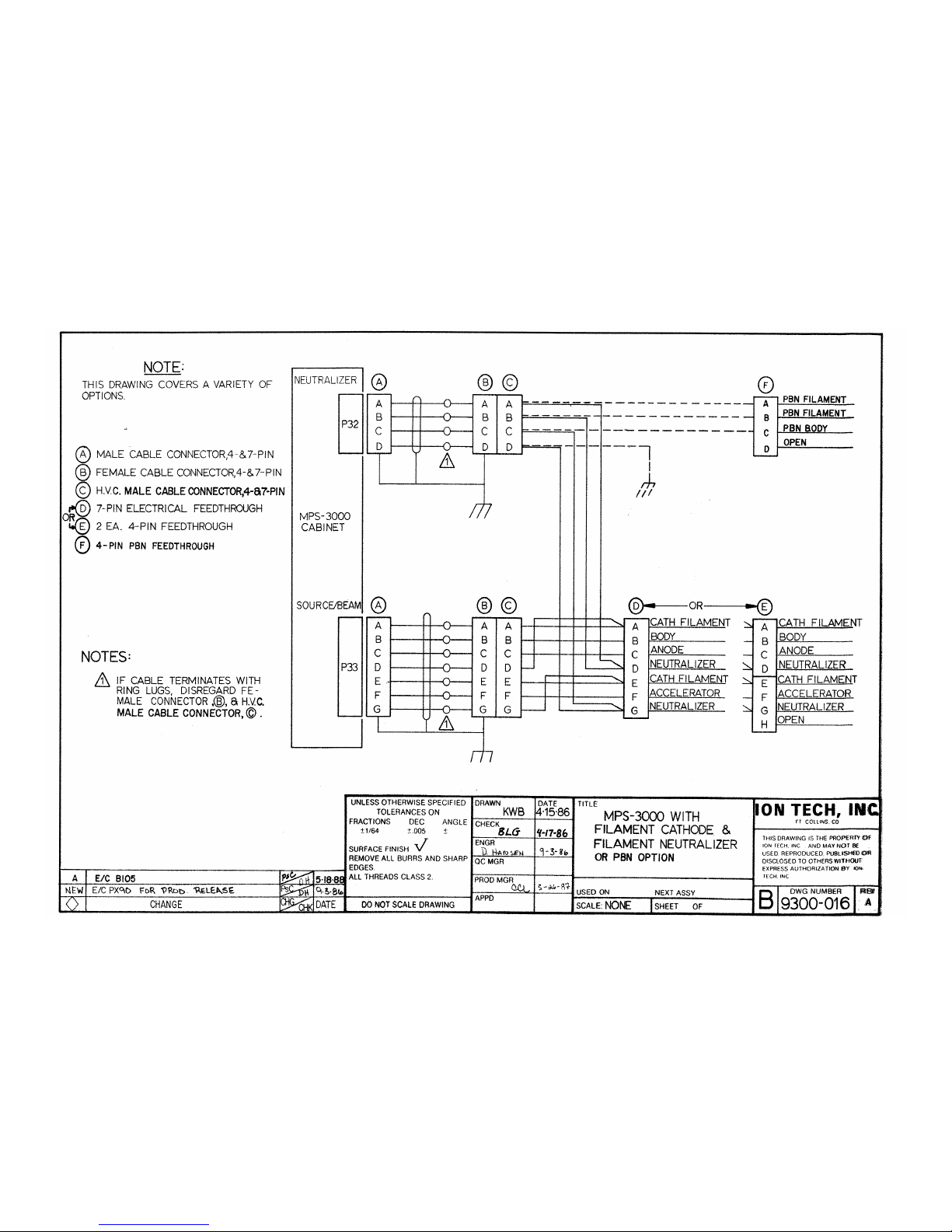
89
Filament Cathode with Filament Neutralizer or PBN Option
Page 94
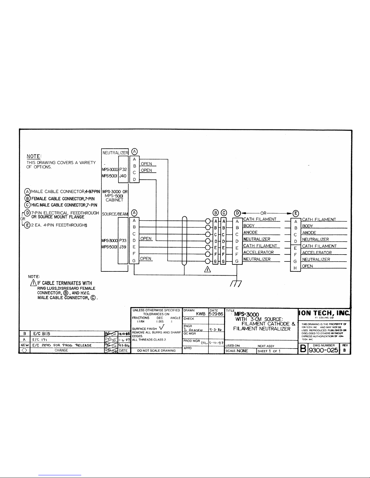
90
3cm Source Filament Cathode and Filament Neutralizer
Page 95
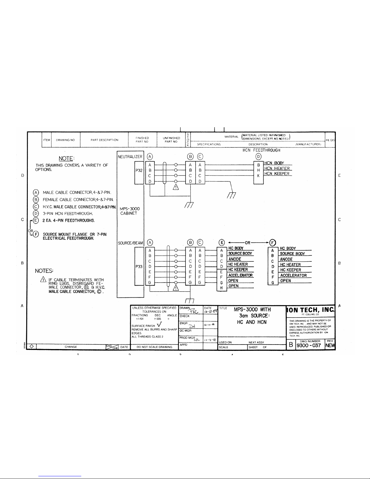
91
3cm Source Hollow Cathode and Hollow Cathode Neutralizer
Page 96
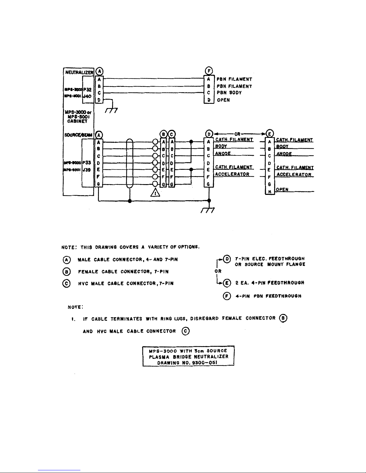
3cm Source Plasma Bridge Neutralizer
92
 Loading...