

Veeco Dektak 150 User Manual


DEKTAK 150 SURFACE PROFILER
USER’S MANUAL
P/N 980-294 (Standard)
P/N 980-298 (Cleanroom)
Revision A

©2007, Veeco Instruments Inc.
All rights reserved.
Printed in the United States of America.
Revision A
COPYRIGHT NOTICE:
This guide and the software (computer program) described in it are copyright © Veeco Instruments Inc.
They are protected by United States copyright laws and international treaty provisions. Under copyright
laws, this guide and the software program contained herein may not be copied, in whole or in part, without
prior written consent of Veeco Instruments Inc., except in the normal use of the software or to make a
backup copy. This exception does not allow copies to be made for others, whether or not sold, but all of
the material purchased (with all backup copies) may be sold, given, or loaned to another person. Under the
law, copying includes translating into another language or format.
Veeco Instruments Inc. retains all rights not otherwise expressly granted here. Nothing in this notice
constitutes a waiver of our rights under U.S. Copyright laws or any other federal or state law.
TRADEMARK NOTICE:
Wyko and Vision are registered trademarks of WYKO Corporation and Veeco Instruments Inc. Microsoft,
Windows and Microsoft Excel are trademarks or registered trademarks of Microsoft Corporation. Dell is
a registered trademark of Dell Computer Corporation. Intel, Pentium and Celeron are trademarks or
registered trademarks of Intel Corporation.
All other brand or product names are trademarks or registered trademarks of their respective holders.
Veeco Instruments Inc.
2650 East Elvira Road
Tucson, Arizona 85706
Phone: (800) 366-9956 or (520) 741-1044
Fax: (520) 294-1799

WARRANTY
Veeco Instruments Inc. Statement of Limited Warranty
This product is covered by the terms of the Veeco standard warranty as in effect on the date of
shipment and as reflected on Veeco's Order Acknowledgement and Quote. While a summary of the
warranty statement is provided below, please refer to the Order Acknowledgement or Quote for a
complete statement of the applicable warranty provisions. In addition, a copy of these warranty terms
may be obtained by contacting Veeco.
WARRANTY. Seller warrants to the original Buyer that new equipment will be free of defects in material and
workmanship for a period of one year commencing (a) on final acceptance or (b) 90 days from shipping,
whichever occurs first. This warranty covers the cost of parts and labor (including, where applicable, field
service labor and travel required to restore the equipment to normal operation).
Seller warrants to the original Buyer that replacement parts will be new or of equal functional quality and
warranted for the remaining portion of the original warranty or 90 days, whichever is longer.
Seller warrants to the original Buyer that software will perform in substantial compliance with the written
materials accompanying the software. Seller does not warrant uninterrupted or error-free operation.
Seller's obligation under these warranties is limited to repairing or replacing at Seller's option defective nonexpendable parts or software. These services will be performed, at Seller's option, at either Seller's facility or
Buyer's business location. For repairs performed at Seller's facility, Buyer must contact Seller in advance for
authorization to return equipment and must follow Seller's shipping instructions. Freight charges and shipments
to Seller are Buyer's responsibility. Seller will return the equipment to Buyer at Seller's expense. All parts used
in making warranty repairs will be new or of equal functional quality.
The warranty obligation of Seller shall not extend to defects that do not impair service or to provide warranty
service beyond normal business hours, Monday through Friday (excluding Seller holidays). No claim will be
allowed for any defect unless Seller shall have received notice of the defect within thirty days following its
discovery by Buyer. Also, no claim will be allowed for equipment damaged in shipment sold under standard
terms of F.O.B. factory. Within thirty days of Buyer's receipt of equipment, Seller must receive notice of any
defect that Buyer could have discovered by prompt inspection. Products shall be considered accepted 30 days
following (a) installation, if Seller performs installation, or (b) shipment; unless written notice of rejection is
provided to Seller within such 30-day period.
Expendable items, including, but not limited to, lamps, pilot lights, filaments, fuses, mechanical pump belts, Vbelts, wafer transport belts, pump fluids, O-rings and seals ARE SPECIFICALLY EXCLUDED FROM THE
FOREGOING WARRANTIES AND ARE NOT WARRANTED. All used equipment is sold 'AS IS, WHERE
IS,' WITHOUT ANY WARRANTY, EXPRESS OR IMPLIED.
iv

Seller assumes no liability under the above warranties for equipment or system failures resulting from (1) abuse,
misuse, modification or mishandling; (2) damage due to forces external to the machine including, but not limited
to, acts of God, flooding, power surges, power failures, defective electrical work, transportation, foreign
equipment/attachments or Buyer-supplied replacement parts or utilities or services such as gas; (3) improper
operation or maintenance or (4) failure to perform preventive maintenance in accordance with Seller's
recommendations (including keeping an accurate log of preventive maintenance). In addition, this warranty does
not apply if any equipment or part has been modified without the written permission of Seller or if any Seller
serial number has been removed or defaced.
No one is authorized to extend or alter these warranties on Seller's behalf without the written
authorization of Seller.
THE ABOVE WARRANTIES ARE EXPRESSLY IN LIEU OF ANY OTHER
EXPRESS OR IMPLIED WARRANTIES (INCLUDING THE WARRANTY OF
MERCHANTABILITY), AND OF ANY OTHER OBLIGATION ON THE PART
OF SELLER. SELLER DOES NOT WARRANT THAT ANY EQUIPMENT OR
SYSTEM CAN BE USED FOR ANY PARTICULAR PURPOSE OR WITH ANY
PARTICULAR PROCESS OTHER THAN THAT COVERED BY THE
APPLICABLE PUBLISHED SPECIFICATIONS.
NO CONSEQUENTIAL DAMAGES. LIMITATION OF LIABILITY. Seller shall not be liable for
consequential damages, for anticipated or lost profits, incidental, indirect, special or punitive damages, loss of
time, loss of use, or other losses, even if advised of the possibility of such damages, incurred by Buyer or any
third party in connection with the equipment or services provided by Seller. In no event will Seller's liability in
connection with the equipment or services provided by Seller exceed the amounts paid to Seller by Buyer
hereunder.
Buyer is advised that, if the equipment is used in a manner not specified by the manufacturer, the protection
provided by the equipment may be impaired.
Notices: The information in this document is subject to change without notice. No Liability is assumed for errors
contained herein or of incidental or consequential damages in connection with the furnishing, performance, or
use of the material.
Document Conventions
GENERAL CONVENTIONS
• Your system hardware operates with the the Dektak® 150 software and Wyko® Vision®
software under Microsoft
hardware under Microsoft Windows XP.
The Dektak 150 and Wyko Vision software follows all Windows XP commands and
conventions of use. If you need a refresher on how to work in the Windows XP environment,
please refer to your Windows software guide.
• When the text indicates that you should enter a key combination (such as A
hold down the appropriate command key (in this case A
key.
• You can perform three basic actions with the buttons on your mouse: clicking, double-clicking,
and dragging. To click, press and release the mouse button. To double-click, press and release
the mouse button twice in rapid succession. To drag, press and hold down the mouse button
while you move the mouse across your desktop.
• Menus are listings of commands or functions that are available to you at certain times. To open
a menu, position the mouse pointer over a menu bar title and click on it with the mouse. A menu
®
Windows XP®. You can also run Wyko Vision independently of
LT-A), press and
LT) and then press the other indicated
v

will pop down from the menu bar. You can then select a command from the pop-down menu by
clicking on it.
• Shortcut menus are available by clicking with the right mouse button on a plot (such as the 3D,
Contour, or Profile plot). You can then select options from the shortcut menu that appears.
• In this manual, the commands you select from pop-down menus are displayed in the following
format: Hardware » Measurement Options. The double arrow symbol (») indicates menu
flow as it cascades down from the menu title.
TYPEFACE CONVENTIONS
This manual uses certain typeface conventions that provide visual cues to help you more easily locate
and identify information.
boldface Menu titles, commands, icons, and check box and button names are shown in
boldface type.
italic type Italic type indicates new terms, title and heading references, and shows
emphasis.
monospace type Code examples and commands that you must type in exactly as they appear are
shown in monospaced type.
SMALL CAPITALS Hardware placards and keyboard key labels are shown in SMALL CAPITALS
(such as E
SC, ENTER, ALT, etc.).
NOTE NOTES contain information that can assist you in using the equipment. An
example is shown in the margin.
CAUTION Whenever you see a CAUTION, there is a possiblity that data will be lost, or
there is some specific action you must perform for the system to work properly.
WARNING Whenever you see a WARNING, there is the possibility of personal injury or
equipment damage.
vi


TABLE OF CONTENTS
Chapter 1. Dektak 150 System Overview . . . . . . . . . . . . . . . . . . . . . . . . . . . . . . . . . . 1-1
System Components . . . . . . . . . . . . . . . . . . . . . . . . . . . . . . . . . . . . . . . . . . . . . . . . . . . . . . . . . . . . . . . .1-2
System Configurations . . . . . . . . . . . . . . . . . . . . . . . . . . . . . . . . . . . . . . . . . . . . . . . . . . . . . . . . . . .1-2
Computer and Software . . . . . . . . . . . . . . . . . . . . . . . . . . . . . . . . . . . . . . . . . . . . . . . . . . . . . . . . . .1-3
Optional Video Monitor . . . . . . . . . . . . . . . . . . . . . . . . . . . . . . . . . . . . . . . . . . . . . . . . . . . . . . . . . . .1-3
Stylus Surface Profiler . . . . . . . . . . . . . . . . . . . . . . . . . . . . . . . . . . . . . . . . . . . . . . . . . . . . . . . . . . .1-3
Environmental Enclosure . . . . . . . . . . . . . . . . . . . . . . . . . . . . . . . . . . . . . . . . . . . . . . . . . . . . . . . . .1-4
USB Video Camera and Optical Assembly. . . . . . . . . . . . . . . . . . . . . . . . . . . . . . . . . . . . . . . . . . . .1-4
Manual X-Y Stage. . . . . . . . . . . . . . . . . . . . . . . . . . . . . . . . . . . . . . . . . . . . . . . . . . . . . . . . . . . . . . .1-4
Options and Accessories . . . . . . . . . . . . . . . . . . . . . . . . . . . . . . . . . . . . . . . . . . . . . . . . . . . . . . . . .1-4
How the System Works . . . . . . . . . . . . . . . . . . . . . . . . . . . . . . . . . . . . . . . . . . . . . . . . . . . . . . . . . . . . . .1-5
Sample Positioning . . . . . . . . . . . . . . . . . . . . . . . . . . . . . . . . . . . . . . . . . . . . . . . . . . . . . . . . . . . . . .1-6
Two-Axis Manual Stage . . . . . . . . . . . . . . . . . . . . . . . . . . . . . . . . . . . . . . . . . . . . . . . . . . . . . . .1-6
X-Y Auto Stage and Single-Axis Y Auto Stage . . . . . . . . . . . . . . . . . . . . . . . . . . . . . . . . . . . . .1-6
Scanning . . . . . . . . . . . . . . . . . . . . . . . . . . . . . . . . . . . . . . . . . . . . . . . . . . . . . . . . . . . . . . . . . .1-6
Profile Manipulation and Measurement . . . . . . . . . . . . . . . . . . . . . . . . . . . . . . . . . . . . . . . . . . . . . .1-6
Measurement Output . . . . . . . . . . . . . . . . . . . . . . . . . . . . . . . . . . . . . . . . . . . . . . . . . . . . . . . . . . . .1-7
Dektak 150 Software Functions . . . . . . . . . . . . . . . . . . . . . . . . . . . . . . . . . . . . . . . . . . . . . . . . . . . . . . .1-7
Automation Programs . . . . . . . . . . . . . . . . . . . . . . . . . . . . . . . . . . . . . . . . . . . . . . . . . . . . . . . . . . . .1-7
Scan Routines. . . . . . . . . . . . . . . . . . . . . . . . . . . . . . . . . . . . . . . . . . . . . . . . . . . . . . . . . . . . . . . . . .1-7
Analytical Functions . . . . . . . . . . . . . . . . . . . . . . . . . . . . . . . . . . . . . . . . . . . . . . . . . . . . . . . . . . . . .1-7
Data Plot Window . . . . . . . . . . . . . . . . . . . . . . . . . . . . . . . . . . . . . . . . . . . . . . . . . . . . . . . . . . . . . . .1-8
Dektak 150 Reference Materials . . . . . . . . . . . . . . . . . . . . . . . . . . . . . . . . . . . . . . . . . . . . . . . . . . . . . . .1-9
Context-Sensitive Help . . . . . . . . . . . . . . . . . . . . . . . . . . . . . . . . . . . . . . . . . . . . . . . . . . . . . . . . . . .1-9
Online Help . . . . . . . . . . . . . . . . . . . . . . . . . . . . . . . . . . . . . . . . . . . . . . . . . . . . . . . . . . . . . . . . . . . .1-9
This Manual in PDF Format . . . . . . . . . . . . . . . . . . . . . . . . . . . . . . . . . . . . . . . . . . . . . . . . . . . . . . .1-9
How to Use This Manual. . . . . . . . . . . . . . . . . . . . . . . . . . . . . . . . . . . . . . . . . . . . . . . . . . . . . . . . . .1-9
Chapter 2. Installing the Dektak 150 System . . . . . . . . . . . . . . . . . . . . . . . . . . . . . . . 2-1
Safety Precautions . . . . . . . . . . . . . . . . . . . . . . . . . . . . . . . . . . . . . . . . . . . . . . . . . . . . . . . . . . . . . . . . .2-1
Profiler Components . . . . . . . . . . . . . . . . . . . . . . . . . . . . . . . . . . . . . . . . . . . . . . . . . . . . . . . . . . . . . . . .2-3
Preparing for Installation . . . . . . . . . . . . . . . . . . . . . . . . . . . . . . . . . . . . . . . . . . . . . . . . . . . . . . . . . . . . .2-4
Preparing Your Location . . . . . . . . . . . . . . . . . . . . . . . . . . . . . . . . . . . . . . . . . . . . . . . . . . . . . . . . . .2-4
vii

Inspecting and Unpacking the Boxes . . . . . . . . . . . . . . . . . . . . . . . . . . . . . . . . . . . . . . . . . . . . . . . 2-5
Unpacking Guidelines. . . . . . . . . . . . . . . . . . . . . . . . . . . . . . . . . . . . . . . . . . . . . . . . . . . . . . . . 2-6
Unpacking the Surface Profiler . . . . . . . . . . . . . . . . . . . . . . . . . . . . . . . . . . . . . . . . . . . . . . . . . . . . 2-6
Removing the Shipping Brackets from the Profiler . . . . . . . . . . . . . . . . . . . . . . . . . . . . . . . . . . . . . 2-8
Installing the System . . . . . . . . . . . . . . . . . . . . . . . . . . . . . . . . . . . . . . . . . . . . . . . . . . . . . . . . . . . . . . . 2-9
Setting Up the Computer. . . . . . . . . . . . . . . . . . . . . . . . . . . . . . . . . . . . . . . . . . . . . . . . . . . . . . . . . 2-9
Connecting the Cables . . . . . . . . . . . . . . . . . . . . . . . . . . . . . . . . . . . . . . . . . . . . . . . . . . . . . . . . . 2-10
Installing the Optical Assembly . . . . . . . . . . . . . . . . . . . . . . . . . . . . . . . . . . . . . . . . . . . . . . . . . . . 2-14
Installing the Stage . . . . . . . . . . . . . . . . . . . . . . . . . . . . . . . . . . . . . . . . . . . . . . . . . . . . . . . . . . . . 2-16
Installing the Stylus . . . . . . . . . . . . . . . . . . . . . . . . . . . . . . . . . . . . . . . . . . . . . . . . . . . . . . . . . . . . 2-18
Turning on the Power and Checking Out the System . . . . . . . . . . . . . . . . . . . . . . . . . . . . . . . . . . 2-20
Adjusting the Optics . . . . . . . . . . . . . . . . . . . . . . . . . . . . . . . . . . . . . . . . . . . . . . . . . . . . . . . . . . . 2-23
Taking a Test Measurement . . . . . . . . . . . . . . . . . . . . . . . . . . . . . . . . . . . . . . . . . . . . . . . . . . . . . 2-25
Turning Off the System . . . . . . . . . . . . . . . . . . . . . . . . . . . . . . . . . . . . . . . . . . . . . . . . . . . . . . . . . 2-27
Installing the Environmental Enclosure. . . . . . . . . . . . . . . . . . . . . . . . . . . . . . . . . . . . . . . . . . . . . 2-27
Installing the Optional Vibration Isolation Table . . . . . . . . . . . . . . . . . . . . . . . . . . . . . . . . . . . . . . . . . 2-28
Installing the Optional Video Monitor. . . . . . . . . . . . . . . . . . . . . . . . . . . . . . . . . . . . . . . . . . . . . . . . . . 2-28
Installing a Printer . . . . . . . . . . . . . . . . . . . . . . . . . . . . . . . . . . . . . . . . . . . . . . . . . . . . . . . . . . . . . . . . 2-29
Establishing a Network Connection. . . . . . . . . . . . . . . . . . . . . . . . . . . . . . . . . . . . . . . . . . . . . . . . . . . 2-29
Changing the Voltage Setting . . . . . . . . . . . . . . . . . . . . . . . . . . . . . . . . . . . . . . . . . . . . . . . . . . . . . . . 2-29
Chapter 3. Basic User Interface and Stage Positioning Techniques . . . . . . . . . . . . 3-1
Start Sequence . . . . . . . . . . . . . . . . . . . . . . . . . . . . . . . . . . . . . . . . . . . . . . . . . . . . . . . . . . . . . . . . . . . 3-1
Power On . . . . . . . . . . . . . . . . . . . . . . . . . . . . . . . . . . . . . . . . . . . . . . . . . . . . . . . . . . . . . . . . . . . . 3-1
Software Interface and Stage Controls . . . . . . . . . . . . . . . . . . . . . . . . . . . . . . . . . . . . . . . . . . . . . . . . . 3-3
Stage Control . . . . . . . . . . . . . . . . . . . . . . . . . . . . . . . . . . . . . . . . . . . . . . . . . . . . . . . . . . . . . . . . . 3-3
Manual X-Y Stage. . . . . . . . . . . . . . . . . . . . . . . . . . . . . . . . . . . . . . . . . . . . . . . . . . . . . . . . . . . . . . 3-3
X-Y Auto Stage and Y Auto Stage . . . . . . . . . . . . . . . . . . . . . . . . . . . . . . . . . . . . . . . . . . . . . . . . . 3-3
Microsoft Windows XP . . . . . . . . . . . . . . . . . . . . . . . . . . . . . . . . . . . . . . . . . . . . . . . . . . . . . . . . . . 3-3
Mouse Functions. . . . . . . . . . . . . . . . . . . . . . . . . . . . . . . . . . . . . . . . . . . . . . . . . . . . . . . . . . . . . . . 3-4
Keyboard Shortcuts. . . . . . . . . . . . . . . . . . . . . . . . . . . . . . . . . . . . . . . . . . . . . . . . . . . . . . . . . . . . . 3-4
Assigning Analytical Functions to Keystrokes. . . . . . . . . . . . . . . . . . . . . . . . . . . . . . . . . . . . . . . . . 3-6
Side Bar Buttons . . . . . . . . . . . . . . . . . . . . . . . . . . . . . . . . . . . . . . . . . . . . . . . . . . . . . . . . . . . . . . . 3-7
X-Y Auto and Y Auto Stage Control Panel . . . . . . . . . . . . . . . . . . . . . . . . . . . . . . . . . . . . . . . . . . . 3-8
Bottom Section of the Stage Control Panel . . . . . . . . . . . . . . . . . . . . . . . . . . . . . . . . . . . . . . 3-11
Working in the Template Editor. . . . . . . . . . . . . . . . . . . . . . . . . . . . . . . . . . . . . . . . . . . . . . . . . . . 3-12
Using the Templates Feature . . . . . . . . . . . . . . . . . . . . . . . . . . . . . . . . . . . . . . . . . . . . . . . . . . . . 3-13
Template Selection. . . . . . . . . . . . . . . . . . . . . . . . . . . . . . . . . . . . . . . . . . . . . . . . . . . . . . . . . 3-13
Sample Loading and Unloading . . . . . . . . . . . . . . . . . . . . . . . . . . . . . . . . . . . . . . . . . . . . . . . . . . . . . 3-13
Positioning the Vertical Standard . . . . . . . . . . . . . . . . . . . . . . . . . . . . . . . . . . . . . . . . . . . . . . . . . 3-15
Stage Tracking . . . . . . . . . . . . . . . . . . . . . . . . . . . . . . . . . . . . . . . . . . . . . . . . . . . . . . . . . . . . . . . . . . 3-16
Viewing the Sample. . . . . . . . . . . . . . . . . . . . . . . . . . . . . . . . . . . . . . . . . . . . . . . . . . . . . . . . . . . . . . . 3-17
Manual Theta Rotation . . . . . . . . . . . . . . . . . . . . . . . . . . . . . . . . . . . . . . . . . . . . . . . . . . . . . . . . . 3-17
Lowering/Raising the Stylus . . . . . . . . . . . . . . . . . . . . . . . . . . . . . . . . . . . . . . . . . . . . . . . . . . . . . . . . 3-18
viii

Optics Illumination Adjustment . . . . . . . . . . . . . . . . . . . . . . . . . . . . . . . . . . . . . . . . . . . . . . . . . . . . . . .3-19
Stylus Reticle Alignment . . . . . . . . . . . . . . . . . . . . . . . . . . . . . . . . . . . . . . . . . . . . . . . . . . . . . . . . . . . .3-19
Feature Reticle Alignment . . . . . . . . . . . . . . . . . . . . . . . . . . . . . . . . . . . . . . . . . . . . . . . . . . . . . . . . . . .3-22
Powering Down . . . . . . . . . . . . . . . . . . . . . . . . . . . . . . . . . . . . . . . . . . . . . . . . . . . . . . . . . . . . . . . . . . .3-23
Chapter 4. Single Scan Operation . . . . . . . . . . . . . . . . . . . . . . . . . . . . . . . . . . . . . . . . 4-1
Loading the Sample . . . . . . . . . . . . . . . . . . . . . . . . . . . . . . . . . . . . . . . . . . . . . . . . . . . . . . . . . . . . . . . .4-1
Making Your Configuration Settings . . . . . . . . . . . . . . . . . . . . . . . . . . . . . . . . . . . . . . . . . . . . . . . . . . . .4-1
Creating a Single-Scan Automation Program . . . . . . . . . . . . . . . . . . . . . . . . . . . . . . . . . . . . . . . . . . . . .4-2
Defining Scan Location and Length . . . . . . . . . . . . . . . . . . . . . . . . . . . . . . . . . . . . . . . . . . . . . . . . .4-4
Running a Scan Routine . . . . . . . . . . . . . . . . . . . . . . . . . . . . . . . . . . . . . . . . . . . . . . . . . . . . . . . . . . . . .4-6
Changing Units Before or After a Scan . . . . . . . . . . . . . . . . . . . . . . . . . . . . . . . . . . . . . . . . . . . . . . . . . .4-8
Reference/Measurement Cursors . . . . . . . . . . . . . . . . . . . . . . . . . . . . . . . . . . . . . . . . . . . . . . . . . . . . . .4-9
Basic Cursor Positioning . . . . . . . . . . . . . . . . . . . . . . . . . . . . . . . . . . . . . . . . . . . . . . . . . . . . . . . . . . . . .4-9
Setting Cursor Bandwidths . . . . . . . . . . . . . . . . . . . . . . . . . . . . . . . . . . . . . . . . . . . . . . . . . . . . . . . . . .4-10
Cursor Positioning with Arrows . . . . . . . . . . . . . . . . . . . . . . . . . . . . . . . . . . . . . . . . . . . . . . . . . . . .4-11
Numeric Entry Cursor Positioning. . . . . . . . . . . . . . . . . . . . . . . . . . . . . . . . . . . . . . . . . . . . . . . . . .4-12
Manual Stage Leveling . . . . . . . . . . . . . . . . . . . . . . . . . . . . . . . . . . . . . . . . . . . . . . . . . . . . . . . . . . . . .4-12
Software Leveling . . . . . . . . . . . . . . . . . . . . . . . . . . . . . . . . . . . . . . . . . . . . . . . . . . . . . . . . . . . . . . . . .4-14
Setting the Zero Point . . . . . . . . . . . . . . . . . . . . . . . . . . . . . . . . . . . . . . . . . . . . . . . . . . . . . . . . . . . . . .4-15
Making a Delta Average Step Height Measurement . . . . . . . . . . . . . . . . . . . . . . . . . . . . . . . . . . . . . . .4-15
Changing the Plot Magnification . . . . . . . . . . . . . . . . . . . . . . . . . . . . . . . . . . . . . . . . . . . . . . . . . . . . . .4-17
Saving the Data Plot . . . . . . . . . . . . . . . . . . . . . . . . . . . . . . . . . . . . . . . . . . . . . . . . . . . . . . . . . . . . . . .4-18
Printing the Scan Data . . . . . . . . . . . . . . . . . . . . . . . . . . . . . . . . . . . . . . . . . . . . . . . . . . . . . . . . . . . . .4-20
Saving an Automation Program . . . . . . . . . . . . . . . . . . . . . . . . . . . . . . . . . . . . . . . . . . . . . . . . . . . . . .4-20
Aborting an Operation . . . . . . . . . . . . . . . . . . . . . . . . . . . . . . . . . . . . . . . . . . . . . . . . . . . . . . . . . . . . . .4-22
Opening a Dektak 150 Scan in Vision. . . . . . . . . . . . . . . . . . . . . . . . . . . . . . . . . . . . . . . . . . . . . . . . . .4-23
Saving upon Exiting the Dektak Program . . . . . . . . . . . . . . . . . . . . . . . . . . . . . . . . . . . . . . . . . . . . . . .4-24
Chapter 5. Multiple Scan Operation. . . . . . . . . . . . . . . . . . . . . . . . . . . . . . . . . . . . . . . 5-1
Loading the Sample . . . . . . . . . . . . . . . . . . . . . . . . . . . . . . . . . . . . . . . . . . . . . . . . . . . . . . . . . . . . . . . .5-1
About the Automation Program . . . . . . . . . . . . . . . . . . . . . . . . . . . . . . . . . . . . . . . . . . . . . . . . . . . . . . .5-1
Opening a New Automation Program . . . . . . . . . . . . . . . . . . . . . . . . . . . . . . . . . . . . . . . . . . . . . . . . . . .5-2
Copying an Automation Program . . . . . . . . . . . . . . . . . . . . . . . . . . . . . . . . . . . . . . . . . . . . . . . . . . . . . .5-3
Program Entry . . . . . . . . . . . . . . . . . . . . . . . . . . . . . . . . . . . . . . . . . . . . . . . . . . . . . . . . . . . . . . . . . . . . .5-3
Defining Scan Location and Length . . . . . . . . . . . . . . . . . . . . . . . . . . . . . . . . . . . . . . . . . . . . . . . . .5-4
Setting Other Scan Routine Options . . . . . . . . . . . . . . . . . . . . . . . . . . . . . . . . . . . . . . . . . . . . . . . . . . . .5-8
About the Scan Routines Window . . . . . . . . . . . . . . . . . . . . . . . . . . . . . . . . . . . . . . . . . . . . . . . . .5-10
Editing Scan Routines. . . . . . . . . . . . . . . . . . . . . . . . . . . . . . . . . . . . . . . . . . . . . . . . . . . . . . . . . . .5-11
Scan Parameters . . . . . . . . . . . . . . . . . . . . . . . . . . . . . . . . . . . . . . . . . . . . . . . . . . . . . . . . . . . . . .5-11
Display Parameters. . . . . . . . . . . . . . . . . . . . . . . . . . . . . . . . . . . . . . . . . . . . . . . . . . . . . . . . . . . . .5-13
Data Processing Settings . . . . . . . . . . . . . . . . . . . . . . . . . . . . . . . . . . . . . . . . . . . . . . . . . . . . . . . .5-15
Analytical Functions . . . . . . . . . . . . . . . . . . . . . . . . . . . . . . . . . . . . . . . . . . . . . . . . . . . . . . . . . . . .5-17
Global Editing of Scan Routine Parameters . . . . . . . . . . . . . . . . . . . . . . . . . . . . . . . . . . . . . . . . . .5-18
ix

Automation Program Options . . . . . . . . . . . . . . . . . . . . . . . . . . . . . . . . . . . . . . . . . . . . . . . . . . . . . . . 5-22
Data File/Data Export . . . . . . . . . . . . . . . . . . . . . . . . . . . . . . . . . . . . . . . . . . . . . . . . . . . . . . . . . . 5-24
Working with APS Reports . . . . . . . . . . . . . . . . . . . . . . . . . . . . . . . . . . . . . . . . . . . . . . . . . . . . . . . . . 5-27
Activating the APS Report Function . . . . . . . . . . . . . . . . . . . . . . . . . . . . . . . . . . . . . . . . . . . . . . . 5-27
Contents of the APS Report . . . . . . . . . . . . . . . . . . . . . . . . . . . . . . . . . . . . . . . . . . . . . . . . . . . . . 5-30
Grid View Tab of the APS Report. . . . . . . . . . . . . . . . . . . . . . . . . . . . . . . . . . . . . . . . . . . . . . 5-30
Plot Tabs of the APS Report . . . . . . . . . . . . . . . . . . . . . . . . . . . . . . . . . . . . . . . . . . . . . . . . . 5-31
Rerunning Selected Scans in the APS Report . . . . . . . . . . . . . . . . . . . . . . . . . . . . . . . . . . . . . . . 5-32
Selecting a Rerun Scan for Viewing . . . . . . . . . . . . . . . . . . . . . . . . . . . . . . . . . . . . . . . . . . . . 5-33
Opening a Saved APS Report . . . . . . . . . . . . . . . . . . . . . . . . . . . . . . . . . . . . . . . . . . . . . . . . . . . 5-33
Exporting an APS Report to Excel . . . . . . . . . . . . . . . . . . . . . . . . . . . . . . . . . . . . . . . . . . . . . . . . 5-34
Enabling MicroForm Measurement . . . . . . . . . . . . . . . . . . . . . . . . . . . . . . . . . . . . . . . . . . . . . . . . . . . 5-35
Setting Printer Options . . . . . . . . . . . . . . . . . . . . . . . . . . . . . . . . . . . . . . . . . . . . . . . . . . . . . . . . . . . . 5-37
Setting the Timing Options . . . . . . . . . . . . . . . . . . . . . . . . . . . . . . . . . . . . . . . . . . . . . . . . . . . . . . . . . 5-37
Adding User Information . . . . . . . . . . . . . . . . . . . . . . . . . . . . . . . . . . . . . . . . . . . . . . . . . . . . . . . . . . . 5-38
Running a Multiple Scan Routine . . . . . . . . . . . . . . . . . . . . . . . . . . . . . . . . . . . . . . . . . . . . . . . . . . . . 5-40
Exporting a Scan Data Plot . . . . . . . . . . . . . . . . . . . . . . . . . . . . . . . . . . . . . . . . . . . . . . . . . . . . . . . . . 5-41
Opening a Saved Scan Data Plot . . . . . . . . . . . . . . . . . . . . . . . . . . . . . . . . . . . . . . . . . . . . . . . . . . . . 5-42
Post-Scan Processing . . . . . . . . . . . . . . . . . . . . . . . . . . . . . . . . . . . . . . . . . . . . . . . . . . . . . . . . . . . . . 5-43
Chapter 6. Analytical Functions. . . . . . . . . . . . . . . . . . . . . . . . . . . . . . . . . . . . . . . . . . 6-1
About Analytical Functions . . . . . . . . . . . . . . . . . . . . . . . . . . . . . . . . . . . . . . . . . . . . . . . . . . . . . . . . . . 6-1
Roughness Parameters. . . . . . . . . . . . . . . . . . . . . . . . . . . . . . . . . . . . . . . . . . . . . . . . . . . . . . . . . . . . . 6-2
Waviness Parameters . . . . . . . . . . . . . . . . . . . . . . . . . . . . . . . . . . . . . . . . . . . . . . . . . . . . . . . . . . . . . . 6-6
Height Parameters. . . . . . . . . . . . . . . . . . . . . . . . . . . . . . . . . . . . . . . . . . . . . . . . . . . . . . . . . . . . . . . . . 6-7
Geometry Parameters . . . . . . . . . . . . . . . . . . . . . . . . . . . . . . . . . . . . . . . . . . . . . . . . . . . . . . . . . . . . . . 6-7
Running a Scan and Leveling the Trace . . . . . . . . . . . . . . . . . . . . . . . . . . . . . . . . . . . . . . . . . . . . . . . . 6-8
Making an Average Roughness Measurement . . . . . . . . . . . . . . . . . . . . . . . . . . . . . . . . . . . . . . . . . . . 6-9
Determining the Cutoff Wavelength. . . . . . . . . . . . . . . . . . . . . . . . . . . . . . . . . . . . . . . . . . . . . . . . . . . 6-10
Short (High) Pass Filter . . . . . . . . . . . . . . . . . . . . . . . . . . . . . . . . . . . . . . . . . . . . . . . . . . . . . 6-11
Long (Low) Pass Filters . . . . . . . . . . . . . . . . . . . . . . . . . . . . . . . . . . . . . . . . . . . . . . . . . . . . . 6-11
Band Pass Filter . . . . . . . . . . . . . . . . . . . . . . . . . . . . . . . . . . . . . . . . . . . . . . . . . . . . . . . . . . . 6-11
Activating the Cutoff Filters . . . . . . . . . . . . . . . . . . . . . . . . . . . . . . . . . . . . . . . . . . . . . . . . . . . . . . . . . 6-11
Entering Filter Cutoffs into a Scan Routine . . . . . . . . . . . . . . . . . . . . . . . . . . . . . . . . . . . . . . . . . . . . . 6-12
Selecting the Data Type . . . . . . . . . . . . . . . . . . . . . . . . . . . . . . . . . . . . . . . . . . . . . . . . . . . . . . . . . . . 6-13
Entering Data Types into a Scan Routine . . . . . . . . . . . . . . . . . . . . . . . . . . . . . . . . . . . . . . . . . . . . . . 6-14
Measuring and Entering Analytical Functions . . . . . . . . . . . . . . . . . . . . . . . . . . . . . . . . . . . . . . . . . . . 6-15
Entering Analytical Functions into a Scan Routine . . . . . . . . . . . . . . . . . . . . . . . . . . . . . . . . . . . . . . . 6-17
Deleting Analytical Functions or Results . . . . . . . . . . . . . . . . . . . . . . . . . . . . . . . . . . . . . . . . . . . . . . 6-18
Using the Smoothing Function . . . . . . . . . . . . . . . . . . . . . . . . . . . . . . . . . . . . . . . . . . . . . . . . . . . . . . 6-18
Activating the Smoothing Function . . . . . . . . . . . . . . . . . . . . . . . . . . . . . . . . . . . . . . . . . . . . . . . . 6-19
Entering Smoothing into a Scan Routine . . . . . . . . . . . . . . . . . . . . . . . . . . . . . . . . . . . . . . . . . . . 6-19
Chapter 7. Scan Routine Parameters . . . . . . . . . . . . . . . . . . . . . . . . . . . . . . . . . . . . . 7-1
Scan Parameters. . . . . . . . . . . . . . . . . . . . . . . . . . . . . . . . . . . . . . . . . . . . . . . . . . . . . . . . . . . . . . . . . . 7-2
x

Using the Scan Parameters Dialog Box . . . . . . . . . . . . . . . . . . . . . . . . . . . . . . . . . . . . . . . . . . . . . .7-2
Scan ID . . . . . . . . . . . . . . . . . . . . . . . . . . . . . . . . . . . . . . . . . . . . . . . . . . . . . . . . . . . . . . . . . . . . . . .7-2
Stylus Type . . . . . . . . . . . . . . . . . . . . . . . . . . . . . . . . . . . . . . . . . . . . . . . . . . . . . . . . . . . . . . . . . . . .7-3
Scan Location . . . . . . . . . . . . . . . . . . . . . . . . . . . . . . . . . . . . . . . . . . . . . . . . . . . . . . . . . . . . . . . . . .7-4
Scan Length . . . . . . . . . . . . . . . . . . . . . . . . . . . . . . . . . . . . . . . . . . . . . . . . . . . . . . . . . . . . . . . . . . .7-5
Scan Duration/Speed . . . . . . . . . . . . . . . . . . . . . . . . . . . . . . . . . . . . . . . . . . . . . . . . . . . . . . . . . . . .7-6
Scan Resolution . . . . . . . . . . . . . . . . . . . . . . . . . . . . . . . . . . . . . . . . . . . . . . . . . . . . . . . . . . . . . . . .7-7
Scan Type. . . . . . . . . . . . . . . . . . . . . . . . . . . . . . . . . . . . . . . . . . . . . . . . . . . . . . . . . . . . . . . . . . . . .7-9
Stylus Force . . . . . . . . . . . . . . . . . . . . . . . . . . . . . . . . . . . . . . . . . . . . . . . . . . . . . . . . . . . . . . . . . . .7-9
Measurement Range . . . . . . . . . . . . . . . . . . . . . . . . . . . . . . . . . . . . . . . . . . . . . . . . . . . . . . . . . . .7-10
Profile . . . . . . . . . . . . . . . . . . . . . . . . . . . . . . . . . . . . . . . . . . . . . . . . . . . . . . . . . . . . . . . . . . . . . . .7-11
Tower Up After Scan. . . . . . . . . . . . . . . . . . . . . . . . . . . . . . . . . . . . . . . . . . . . . . . . . . . . . . . . . . . .7-13
Deflection Scan. . . . . . . . . . . . . . . . . . . . . . . . . . . . . . . . . . . . . . . . . . . . . . . . . . . . . . . . . . . . . . . .7-14
Display Parameters . . . . . . . . . . . . . . . . . . . . . . . . . . . . . . . . . . . . . . . . . . . . . . . . . . . . . . . . . . . . . . . .7-15
Software Leveling . . . . . . . . . . . . . . . . . . . . . . . . . . . . . . . . . . . . . . . . . . . . . . . . . . . . . . . . . . . . . .7-16
Reference/Measurement Cursors. . . . . . . . . . . . . . . . . . . . . . . . . . . . . . . . . . . . . . . . . . . . . . . . . .7-17
Entering Cursor Positions from the Data Plot Window . . . . . . . . . . . . . . . . . . . . . . . . . . . . . . .7-17
Display Range. . . . . . . . . . . . . . . . . . . . . . . . . . . . . . . . . . . . . . . . . . . . . . . . . . . . . . . . . . . . . . . . .7-18
Display Data Type. . . . . . . . . . . . . . . . . . . . . . . . . . . . . . . . . . . . . . . . . . . . . . . . . . . . . . . . . . . . . .7-18
Data Processing Parameters . . . . . . . . . . . . . . . . . . . . . . . . . . . . . . . . . . . . . . . . . . . . . . . . . . . . . . . .7-19
Filter Cutoffs . . . . . . . . . . . . . . . . . . . . . . . . . . . . . . . . . . . . . . . . . . . . . . . . . . . . . . . . . . . . . . . . . .7-19
Smoothing. . . . . . . . . . . . . . . . . . . . . . . . . . . . . . . . . . . . . . . . . . . . . . . . . . . . . . . . . . . . . . . . . . . .7-20
Step Detection . . . . . . . . . . . . . . . . . . . . . . . . . . . . . . . . . . . . . . . . . . . . . . . . . . . . . . . . . . . . . . . .7-21
Chapter 8. Menu and Toolbar Descriptions . . . . . . . . . . . . . . . . . . . . . . . . . . . . . . . . 8-1
Startup Window . . . . . . . . . . . . . . . . . . . . . . . . . . . . . . . . . . . . . . . . . . . . . . . . . . . . . . . . . . . . . . . . . . . .8-1
Default Menu Bar . . . . . . . . . . . . . . . . . . . . . . . . . . . . . . . . . . . . . . . . . . . . . . . . . . . . . . . . . . . . . . .8-2
Additional Menus . . . . . . . . . . . . . . . . . . . . . . . . . . . . . . . . . . . . . . . . . . . . . . . . . . . . . . . . . . . . . . .8-2
Toolbar . . . . . . . . . . . . . . . . . . . . . . . . . . . . . . . . . . . . . . . . . . . . . . . . . . . . . . . . . . . . . . . . . . . .8-2
Status Bar. . . . . . . . . . . . . . . . . . . . . . . . . . . . . . . . . . . . . . . . . . . . . . . . . . . . . . . . . . . . . . . . . .8-2
File Menu. . . . . . . . . . . . . . . . . . . . . . . . . . . . . . . . . . . . . . . . . . . . . . . . . . . . . . . . . . . . . . . . . . . . . . . . .8-2
Run Menu . . . . . . . . . . . . . . . . . . . . . . . . . . . . . . . . . . . . . . . . . . . . . . . . . . . . . . . . . . . . . . . . . . . . . . . .8-4
Profiler Menu . . . . . . . . . . . . . . . . . . . . . . . . . . . . . . . . . . . . . . . . . . . . . . . . . . . . . . . . . . . . . . . . . . . . . .8-5
Setup Menu . . . . . . . . . . . . . . . . . . . . . . . . . . . . . . . . . . . . . . . . . . . . . . . . . . . . . . . . . . . . . . . . . . . . . . .8-7
User Interface Settings . . . . . . . . . . . . . . . . . . . . . . . . . . . . . . . . . . . . . . . . . . . . . . . . . . . . . . . . . . . . . .8-8
Directories. . . . . . . . . . . . . . . . . . . . . . . . . . . . . . . . . . . . . . . . . . . . . . . . . . . . . . . . . . . . . . . . . . . . .8-8
Data Processing . . . . . . . . . . . . . . . . . . . . . . . . . . . . . . . . . . . . . . . . . . . . . . . . . . . . . . . . . . . . . . . .8-8
Shortcuts. . . . . . . . . . . . . . . . . . . . . . . . . . . . . . . . . . . . . . . . . . . . . . . . . . . . . . . . . . . . . . . . . . . . . .8-9
Units . . . . . . . . . . . . . . . . . . . . . . . . . . . . . . . . . . . . . . . . . . . . . . . . . . . . . . . . . . . . . . . . . . . . . . . .8-10
Visual . . . . . . . . . . . . . . . . . . . . . . . . . . . . . . . . . . . . . . . . . . . . . . . . . . . . . . . . . . . . . . . . . . . . . . .8-11
Hardware Settings. . . . . . . . . . . . . . . . . . . . . . . . . . . . . . . . . . . . . . . . . . . . . . . . . . . . . . . . . . . . . . . . .8-12
Illumination . . . . . . . . . . . . . . . . . . . . . . . . . . . . . . . . . . . . . . . . . . . . . . . . . . . . . . . . . . . . . . . . . . .8-12
Soft Touchdown . . . . . . . . . . . . . . . . . . . . . . . . . . . . . . . . . . . . . . . . . . . . . . . . . . . . . . . . . . . . . . .8-12
Calibration Menu . . . . . . . . . . . . . . . . . . . . . . . . . . . . . . . . . . . . . . . . . . . . . . . . . . . . . . . . . . . . . . . . . .8-13
Window Menu . . . . . . . . . . . . . . . . . . . . . . . . . . . . . . . . . . . . . . . . . . . . . . . . . . . . . . . . . . . . . . . . . . . .8-14
xi

Help Menu . . . . . . . . . . . . . . . . . . . . . . . . . . . . . . . . . . . . . . . . . . . . . . . . . . . . . . . . . . . . . . . . . . . . . . 8-16
General Tab . . . . . . . . . . . . . . . . . . . . . . . . . . . . . . . . . . . . . . . . . . . . . . . . . . . . . . . . . . . . . . . . . 8-16
Installed Options Tab . . . . . . . . . . . . . . . . . . . . . . . . . . . . . . . . . . . . . . . . . . . . . . . . . . . . . . . . . . 8-17
Automation Programs Window Menu Selections . . . . . . . . . . . . . . . . . . . . . . . . . . . . . . . . . . . . . . . . 8-18
Edit Menu . . . . . . . . . . . . . . . . . . . . . . . . . . . . . . . . . . . . . . . . . . . . . . . . . . . . . . . . . . . . . . . . . . . 8-18
Scan Routines Window Menu Selections . . . . . . . . . . . . . . . . . . . . . . . . . . . . . . . . . . . . . . . . . . . . . . 8-19
Edit Menu . . . . . . . . . . . . . . . . . . . . . . . . . . . . . . . . . . . . . . . . . . . . . . . . . . . . . . . . . . . . . . . . . . . 8-29
Sample Positioning Window Pop-Up Menu Selections . . . . . . . . . . . . . . . . . . . . . . . . . . . . . . . . . . . . 8-20
Data Plot Window Menu Selections . . . . . . . . . . . . . . . . . . . . . . . . . . . . . . . . . . . . . . . . . . . . . . . . . . 8-23
Edit Menu . . . . . . . . . . . . . . . . . . . . . . . . . . . . . . . . . . . . . . . . . . . . . . . . . . . . . . . . . . . . . . . . . . . 8-23
Plot Menu . . . . . . . . . . . . . . . . . . . . . . . . . . . . . . . . . . . . . . . . . . . . . . . . . . . . . . . . . . . . . . . . . . . 8-23
Analysis Menu. . . . . . . . . . . . . . . . . . . . . . . . . . . . . . . . . . . . . . . . . . . . . . . . . . . . . . . . . . . . . . . . 8-25
Dektak Database Window . . . . . . . . . . . . . . . . . . . . . . . . . . . . . . . . . . . . . . . . . . . . . . . . . . . . . . . . . . 8-27
File Menu . . . . . . . . . . . . . . . . . . . . . . . . . . . . . . . . . . . . . . . . . . . . . . . . . . . . . . . . . . . . . . . . . . . 8-27
Window Menu . . . . . . . . . . . . . . . . . . . . . . . . . . . . . . . . . . . . . . . . . . . . . . . . . . . . . . . . . . . . . . . . 8-27
Help Menu . . . . . . . . . . . . . . . . . . . . . . . . . . . . . . . . . . . . . . . . . . . . . . . . . . . . . . . . . . . . . . . . .. . . 8-27
Toolbars and Icons . . . . . . . . . . . . . . . . . . . . . . . . . . . . . . . . . . . . . . . . . . . . . . . . . . . . . . . . . . . . . . . 8-27
Customizing the Toolbars . . . . . . . . . . . . . . . . . . . . . . . . . . . . . . . . . . . . . . . . . . . . . . . . . . . . . . . 8-28
Startup Window Toolbar and Icons . . . . . . . . . . . . . . . . . . . . . . . . . . . . . . . . . . . . . . . . . . . . . . . . 8-29
Automation Programs Window Toolbar and Icons . . . . . . . . . . . . . . . . . . . . . . . . . . . . . . . . . . . . 8-30
Scan Routines Window Toolbar and Icons . . . . . . . . . . . . . . . . . . . . . . . . . . . . . . . . . . . . . . . . . . 8-31
Sample Positioning Window Toolbar and Icons . . . . . . . . . . . . . . . . . . . . . . . . . . . . . . . . . . . . . . 8-32
Data Plot Window Toolbar and Icons . . . . . . . . . . . . . . . . . . . . . . . . . . . . . . . . . . . . . . . . . . . . . . 8-34
Dektak Database Toolbar and Icons. . . . . . . . . . . . . . . . . . . . . . . . . . . . . . . . . . . . . . . . . . . . . . . 8-35
Chapter 9. Calibration and Maintenance. . . . . . . . . . . . . . . . . . . . . . . . . . . . . . . . . . . 9-1
Overview of Vertical Calibration . . . . . . . . . . . . . . . . . . . . . . . . . . . . . . . . . . . . . . . . . . . . . . . . . . . . . . 9-1
Calibrating the 65 kÅ Range . . . . . . . . . . . . . . . . . . . . . . . . . . . . . . . . . . . . . . . . . . . . . . . . . . . . . . . . . 9-2
Making the Preliminary Measurements. . . . . . . . . . . . . . . . . . . . . . . . . . . . . . . . . . . . . . . . . . . . . . 9-2
Calculating the Average Step Height . . . . . . . . . . . . . . . . . . . . . . . . . . . . . . . . . . . . . . . . . . . . 9-4
Setting the Vertical Calibration . . . . . . . . . . . . . . . . . . . . . . . . . . . . . . . . . . . . . . . . . . . . . . . . . 9-5
Calibrating the Other Ranges . . . . . . . . . . . . . . . . . . . . . . . . . . . . . . . . . . . . . . . . . . . . . . . . . . . . . . . . 9-6
Calibrating the Optional 1 mm Range . . . . . . . . . . . . . . . . . . . . . . . . . . . . . . . . . . . . . . . . . . . . . . . 9-6
General Care and Handling. . . . . . . . . . . . . . . . . . . . . . . . . . . . . . . . . . . . . . . . . . . . . . . . . . . . . . . . . . 9-6
Cleaning the Profiler . . . . . . . . . . . . . . . . . . . . . . . . . . . . . . . . . . . . . . . . . . . . . . . . . . . . . . . . . . . . . . . 9-7
Stylus Replacement and Tip Cleaning . . . . . . . . . . . . . . . . . . . . . . . . . . . . . . . . . . . . . . . . . . . . . . . . . 9-7
Removing the Stylus . . . . . . . . . . . . . . . . . . . . . . . . . . . . . . . . . . . . . . . . . . . . . . . . . . . . . . . . . . . . 9-8
Installing a New Stylus . . . . . . . . . . . . . . . . . . . . . . . . . . . . . . . . . . . . . . . . . . . . . . . . . . . . . . . . . 9-11
Cleaning the Stylus . . . . . . . . . . . . . . . . . . . . . . . . . . . . . . . . . . . . . . . . . . . . . . . . . . . . . . . . . . . . 9-13
Cleaning the X-Y Stage and Block . . . . . . . . . . . . . . . . . . . . . . . . . . . . . . . . . . . . . . . . . . . . . . . . . . . 9-14
Adjusting the Optics. . . . . . . . . . . . . . . . . . . . . . . . . . . . . . . . . . . . . . . . . . . . . . . . . . . . . . . . . . . . . . . 9-17
Adjusting the Standard Fixed Optics. . . . . . . . . . . . . . . . . . . . . . . . . . . . . . . . . . . . . . . . . . . . . . . 9-18
Adjusting the Optional Zoom Optics . . . . . . . . . . . . . . . . . . . . . . . . . . . . . . . . . . . . . . . . . . . . . . . 9-20
Adjusting the Coarse Alignment . . . . . . . . . . . . . . . . . . . . . . . . . . . . . . . . . . . . . . . . . . . . . . . . . . . . . 9-22
xii

Service Contracts . . . . . . . . . . . . . . . . . . . . . . . . . . . . . . . . . . . . . . . . . . . . . . . . . . . . . . . . . . . . . . . . .9-22
Major Repairs . . . . . . . . . . . . . . . . . . . . . . . . . . . . . . . . . . . . . . . . . . . . . . . . . . . . . . . . . . . . . . . . . . . .9-22
Appendix A. Facilities Specifications . . . . . . . . . . . . . . . . . . . . . . . . . . . . . . . . . . . . . A-1
Vibration Interference . . . . . . . . . . . . . . . . . . . . . . . . . . . . . . . . . . . . . . . . . . . . . . . . . . . . . . . . . . . . . . A-2
Floor . . . . . . . . . . . . . . . . . . . . . . . . . . . . . . . . . . . . . . . . . . . . . . . . . . . . . . . . . . . . . . . . . . . . . . . . . . . A-2
System Location and Service Access . . . . . . . . . . . . . . . . . . . . . . . . . . . . . . . . . . . . . . . . . . . . . . . . . A-2
Cable Connections. . . . . . . . . . . . . . . . . . . . . . . . . . . . . . . . . . . . . . . . . . . . . . . . . . . . . . . . . . . . . . . . A-3
Dektak 150 Dimensions with Enclosure . . . . . . . . . . . . . . . . . . . . . . . . . . . . . . . . . . . . . . . . . . . . . . . . A-3
Dektak 150 Dimensions without Enclosure . . . . . . . . . . . . . . . . . . . . . . . . . . . . . . . . . . . . . . . . . . . . . A-5
Appendix B. Technical Specifications and Purchased Options . . . . . . . . . . . . . . . . B-1
Dektak 150 Technical Specifications . . . . . . . . . . . . . . . . . . . . . . . . . . . . . . . . . . . . . . . . . . . . . . . . . . . . . . B-1
Dektak 150 Purchased Options . . . . . . . . . . . . . . . . . . . . . . . . . . . . . . . . . . . . . . . . . . . . . . . . . . . . . . B-3
Appendix C. Stress Measurement . . . . . . . . . . . . . . . . . . . . . . . . . . . . . . . . . . . . . . . . C-1
Three-Point Substrate Suspension . . . . . . . . . . . . . . . . . . . . . . . . . . . . . . . . . . . . . . . . . . . . . . . . . . . . C-2
Creating a Stress Reference . . . . . . . . . . . . . . . . . . . . . . . . . . . . . . . . . . . . . . . . . . . . . . . . . . . . . . . . . C-3
Identifying Substrate Characteristics. . . . . . . . . . . . . . . . . . . . . . . . . . . . . . . . . . . . . . . . . . . . . . . . . . . C-3
Entering Stress Parameters . . . . . . . . . . . . . . . . . . . . . . . . . . . . . . . . . . . . . . . . . . . . . . . . . . . . . . . . . C-5
Stress Results . . . . . . . . . . . . . . . . . . . . . . . . . . . . . . . . . . . . . . . . . . . . . . . . . . . . . . . . . . . . . . . . . . . . C-5
Constraints and Limitations. . . . . . . . . . . . . . . . . . . . . . . . . . . . . . . . . . . . . . . . . . . . . . . . . . . . . . . C-6
Appendix D. Step Detection Function . . . . . . . . . . . . . . . . . . . . . . . . . . . . . . . . . . . . . D-1
Step Detection Method . . . . . . . . . . . . . . . . . . . . . . . . . . . . . . . . . . . . . . . . . . . . . . . . . . . . . . . . . . . . . D-1
Step Detection Parameters . . . . . . . . . . . . . . . . . . . . . . . . . . . . . . . . . . . . . . . . . . . . . . . . . . . . . . . . . . D-1
General Settings Tab . . . . . . . . . . . . . . . . . . . . . . . . . . . . . . . . . . . . . . . . . . . . . . . . . . . . . . . . . . . D-2
Detection Method Section . . . . . . . . . . . . . . . . . . . . . . . . . . . . . . . . . . . . . . . . . . . . . . . . . . . . D-2
Detection Range Section . . . . . . . . . . . . . . . . . . . . . . . . . . . . . . . . . . . . . . . . . . . . . . . . . . . . . D-3
Automatic Leveling . . . . . . . . . . . . . . . . . . . . . . . . . . . . . . . . . . . . . . . . . . . . . . . . . . . . . . . . . . D-3
Save Changes To Scan Routine . . . . . . . . . . . . . . . . . . . . . . . . . . . . . . . . . . . . . . . . . . . . . . . D-3
Enable Step Detection . . . . . . . . . . . . . . . . . . . . . . . . . . . . . . . . . . . . . . . . . . . . . . . . . . . . . . . D-3
Every Step Tab . . . . . . . . . . . . . . . . . . . . . . . . . . . . . . . . . . . . . . . . . . . . . . . . . . . . . . . . . . . . . . . . D-4
Step Description Section . . . . . . . . . . . . . . . . . . . . . . . . . . . . . . . . . . . . . . . . . . . . . . . . . . . . . D-4
Analytical Functions Section . . . . . . . . . . . . . . . . . . . . . . . . . . . . . . . . . . . . . . . . . . . . . . . . . . D-4
First Step Tab . . . . . . . . . . . . . . . . . . . . . . . . . . . . . . . . . . . . . . . . . . . . . . . . . . . . . . . . . . . . . . . . . D-5
Step Description Section . . . . . . . . . . . . . . . . . . . . . . . . . . . . . . . . . . . . . . . . . . . . . . . . . . . . . D-5
Distance To Step Section. . . . . . . . . . . . . . . . . . . . . . . . . . . . . . . . . . . . . . . . . . . . . . . . . . . . . D-5
Band Width Section . . . . . . . . . . . . . . . . . . . . . . . . . . . . . . . . . . . . . . . . . . . . . . . . . . . . . . . . . D-6
Additional Parameters . . . . . . . . . . . . . . . . . . . . . . . . . . . . . . . . . . . . . . . . . . . . . . . . . . . . . . . D-6
Analytical Functions Section . . . . . . . . . . . . . . . . . . . . . . . . . . . . . . . . . . . . . . . . . . . . . . . . . . D-6
Step Detection Setup . . . . . . . . . . . . . . . . . . . . . . . . . . . . . . . . . . . . . . . . . . . . . . . . . . . . . . . . . . . . . . D-7
Performing Step Detection on a Single Scan . . . . . . . . . . . . . . . . . . . . . . . . . . . . . . . . . . . . . . . . . D-8
Programming Step Detection in a Scan Routine . . . . . . . . . . . . . . . . . . . . . . . . . . . . . . . . . . . . . . D-8
Programming Step Detection on Multiple Scans . . . . . . . . . . . . . . . . . . . . . . . . . . . . . . . . . . . . . . D-8
xiii

Appendix E. 3D Mapping Function . . . . . . . . . . . . . . . . . . . . . . . . . . . . . . . . . . . . . . . E-1
Overview . . . . . . . . . . . . . . . . . . . . . . . . . . . . . . . . . . . . . . . . . . . . . . . . . . . . . . . . . . . . . . . . . . . . . . . . E-1
Hardware. . . . . . . . . . . . . . . . . . . . . . . . . . . . . . . . . . . . . . . . . . . . . . . . . . . . . . . . . . . . . . . . . . . . . E-1
Software . . . . . . . . . . . . . . . . . . . . . . . . . . . . . . . . . . . . . . . . . . . . . . . . . . . . . . . . . . . . . . . . . . . . . E-1
Setting Up a 3D Mapping Program . . . . . . . . . . . . . . . . . . . . . . . . . . . . . . . . . . . . . . . . . . . . . . . . . . . . E-2
Steps for the Y Auto Stage . . . . . . . . . . . . . . . . . . . . . . . . . . . . . . . . . . . . . . . . . . . . . . . . . . . . . . . E-2
Steps for the X-Y Auto Stage . . . . . . . . . . . . . . . . . . . . . . . . . . . . . . . . . . . . . . . . . . . . . . . . . . . . . E-3
Selecting Files for Saving Mapping Data. . . . . . . . . . . . . . . . . . . . . . . . . . . . . . . . . . . . . . . . . . . . . . . . E-4
Running a 3D Mapping Program . . . . . . . . . . . . . . . . . . . . . . . . . . . . . . . . . . . . . . . . . . . . . . . . . . . . . . E-5
About Soft Touchdown . . . . . . . . . . . . . . . . . . . . . . . . . . . . . . . . . . . . . . . . . . . . . . . . . . . . . . . . . . . . . E-5
Modifying the Soft Touchdown Settings . . . . . . . . . . . . . . . . . . . . . . . . . . . . . . . . . . . . . . . . . . . . . . . . E-5
Checking Stylus Operation after Calibration . . . . . . . . . . . . . . . . . . . . . . . . . . . . . . . . . . . . . . . . . . E-7
Troubleshooting Soft Touchdown Problems . . . . . . . . . . . . . . . . . . . . . . . . . . . . . . . . . . . . . . . . . . E-7
Entering Soft Touchdown into a Scan Routine . . . . . . . . . . . . . . . . . . . . . . . . . . . . . . . . . . . . . . . . . . . E-7
Using Vision’s Basic Functions . . . . . . . . . . . . . . . . . . . . . . . . . . . . . . . . . . . . . . . . . . . . . . . . . . . . . . . E-8
Start-Up Window . . . . . . . . . . . . . . . . . . . . . . . . . . . . . . . . . . . . . . . . . . . . . . . . . . . . . . . . . . . . . . . E-8
Open . . . . . . . . . . . . . . . . . . . . . . . . . . . . . . . . . . . . . . . . . . . . . . . . . . . . . . . . . . . . . . . . . . . . . . . . E-9
Save . . . . . . . . . . . . . . . . . . . . . . . . . . . . . . . . . . . . . . . . . . . . . . . . . . . . . . . . . . . . . . . . . . . . . . . E-10
Printing . . . . . . . . . . . . . . . . . . . . . . . . . . . . . . . . . . . . . . . . . . . . . . . . . . . . . . . . . . . . . . . . . . . . . E-10
Vision Toolbar . . . . . . . . . . . . . . . . . . . . . . . . . . . . . . . . . . . . . . . . . . . . . . . . . . . . . . . . . . . . . . . . E-10
Analyzing Data . . . . . . . . . . . . . . . . . . . . . . . . . . . . . . . . . . . . . . . . . . . . . . . . . . . . . . . . . . . . . . . . . . E-12
Datasets . . . . . . . . . . . . . . . . . . . . . . . . . . . . . . . . . . . . . . . . . . . . . . . . . . . . . . . . . . . . . . . . . . . . E-12
Processed Options . . . . . . . . . . . . . . . . . . . . . . . . . . . . . . . . . . . . . . . . . . . . . . . . . . . . . . . . . . . . E-12
Terms Removal Options. . . . . . . . . . . . . . . . . . . . . . . . . . . . . . . . . . . . . . . . . . . . . . . . . . . . . E-12
Filtering Options . . . . . . . . . . . . . . . . . . . . . . . . . . . . . . . . . . . . . . . . . . . . . . . . . . . . . . . . . . E-14
Masking Options. . . . . . . . . . . . . . . . . . . . . . . . . . . . . . . . . . . . . . . . . . . . . . . . . . . . . . . . . . . E-15
Dektak Options . . . . . . . . . . . . . . . . . . . . . . . . . . . . . . . . . . . . . . . . . . . . . . . . . . . . . . . . . . . . E-16
Displaying Data . . . . . . . . . . . . . . . . . . . . . . . . . . . . . . . . . . . . . . . . . . . . . . . . . . . . . . . . . . . . . . . . . . E-19
Setting the Units . . . . . . . . . . . . . . . . . . . . . . . . . . . . . . . . . . . . . . . . . . . . . . . . . . . . . . . . . . . . . . E-19
Standard Display File . . . . . . . . . . . . . . . . . . . . . . . . . . . . . . . . . . . . . . . . . . . . . . . . . . . . . . . . . . E-19
Display Files for Each Analysis. . . . . . . . . . . . . . . . . . . . . . . . . . . . . . . . . . . . . . . . . . . . . . . . . . . E-19
Display Custom Files (.cdf) . . . . . . . . . . . . . . . . . . . . . . . . . . . . . . . . . . . . . . . . . . . . . . . . . . . . . . E-20
Selecting a Default Output File . . . . . . . . . . . . . . . . . . . . . . . . . . . . . . . . . . . . . . . . . . . . . . . . . . . E-20
Setting Titles and User Notes . . . . . . . . . . . . . . . . . . . . . . . . . . . . . . . . . . . . . . . . . . . . . . . . . . . . E-21
Standard Plots. . . . . . . . . . . . . . . . . . . . . . . . . . . . . . . . . . . . . . . . . . . . . . . . . . . . . . . . . . . . . . . . E-21
Contour Plot . . . . . . . . . . . . . . . . . . . . . . . . . . . . . . . . . . . . . . . . . . . . . . . . . . . . . . . . . . . . . . E-22
Surface Plot . . . . . . . . . . . . . . . . . . . . . . . . . . . . . . . . . . . . . . . . . . . . . . . . . . . . . . . . . . . . . . E-23
Height (Z) Scale . . . . . . . . . . . . . . . . . . . . . . . . . . . . . . . . . . . . . . . . . . . . . . . . . . . . . . . . . . . E-23
Plot Options Menu . . . . . . . . . . . . . . . . . . . . . . . . . . . . . . . . . . . . . . . . . . . . . . . . . . . . . . . . . E-23
2D Analysis. . . . . . . . . . . . . . . . . . . . . . . . . . . . . . . . . . . . . . . . . . . . . . . . . . . . . . . . . . . . . . . E-24
3D Interactive Plot . . . . . . . . . . . . . . . . . . . . . . . . . . . . . . . . . . . . . . . . . . . . . . . . . . . . . . . . . E-26
Filtered Histogram . . . . . . . . . . . . . . . . . . . . . . . . . . . . . . . . . . . . . . . . . . . . . . . . . . . . . . . . . E-27
Filtered Bearing Ratio Analysis Plot . . . . . . . . . . . . . . . . . . . . . . . . . . . . . . . . . . . . . . . . . . . . E-29
xiv

Masking . . . . . . . . . . . . . . . . . . . . . . . . . . . . . . . . . . . . . . . . . . . . . . . . . . . . . . . . . . . . . . . . . . . . . . . . E-31
Analysis Mask . . . . . . . . . . . . . . . . . . . . . . . . . . . . . . . . . . . . . . . . . . . . . . . . . . . . . . . . . . . . . . . . E-32
Terms Mask . . . . . . . . . . . . . . . . . . . . . . . . . . . . . . . . . . . . . . . . . . . . . . . . . . . . . . . . . . . . . . . . . E-32
Height Threshold (Histogram) Mask . . . . . . . . . . . . . . . . . . . . . . . . . . . . . . . . . . . . . . . . . . . . . . . E-32
Detector Mask. . . . . . . . . . . . . . . . . . . . . . . . . . . . . . . . . . . . . . . . . . . . . . . . . . . . . . . . . . . . . . . . E-32
Loading and Saving Masks. . . . . . . . . . . . . . . . . . . . . . . . . . . . . . . . . . . . . . . . . . . . . . . . . . . . . . E-32
Creating and Editing Masks . . . . . . . . . . . . . . . . . . . . . . . . . . . . . . . . . . . . . . . . . . . . . . . . . . . . . E-33
Height Threshold (Histogram) Masks . . . . . . . . . . . . . . . . . . . . . . . . . . . . . . . . . . . . . . . . . . . . . . E-34
Selecting Mask Views . . . . . . . . . . . . . . . . . . . . . . . . . . . . . . . . . . . . . . . . . . . . . . . . . . . . . . . . . . E-34
Selecting Data Displays . . . . . . . . . . . . . . . . . . . . . . . . . . . . . . . . . . . . . . . . . . . . . . . . . . . . . . . . E-35
Saving Masks . . . . . . . . . . . . . . . . . . . . . . . . . . . . . . . . . . . . . . . . . . . . . . . . . . . . . . . . . . . . . . . . E-35
Applying a Detector Mask . . . . . . . . . . . . . . . . . . . . . . . . . . . . . . . . . . . . . . . . . . . . . . . . . . . . . . . E-35
Applying an Analysis or Terms Mask to a New Measurement . . . . . . . . . . . . . . . . . . . . . . . . . . . E-35
Applying a Saved Mask to an Existing Dataset . . . . . . . . . . . . . . . . . . . . . . . . . . . . . . . . . . . . . . E-36
Saving a Mask to a Configuration File . . . . . . . . . . . . . . . . . . . . . . . . . . . . . . . . . . . . . . . . . . . . . E-36
Datasets and Databases . . . . . . . . . . . . . . . . . . . . . . . . . . . . . . . . . . . . . . . . . . . . . . . . . . . . . . . . . . . E-36
Appendix F. N-Lite Option . . . . . . . . . . . . . . . . . . . . . . . . . . . . . . . . . . . . . . . . . . . . . . F-1
About the N-Lite Option. . . . . . . . . . . . . . . . . . . . . . . . . . . . . . . . . . . . . . . . . . . . . . . . . . . . . . . . . . . . . F-1
Main Functions . . . . . . . . . . . . . . . . . . . . . . . . . . . . . . . . . . . . . . . . . . . . . . . . . . . . . . . . . . . . . . . . . . . F-2
Servoed Engage . . . . . . . . . . . . . . . . . . . . . . . . . . . . . . . . . . . . . . . . . . . . . . . . . . . . . . . . . . . . . . . F-2
Fine Positioning . . . . . . . . . . . . . . . . . . . . . . . . . . . . . . . . . . . . . . . . . . . . . . . . . . . . . . . . . . . . . . . F-2
Stylus Retouch . . . . . . . . . . . . . . . . . . . . . . . . . . . . . . . . . . . . . . . . . . . . . . . . . . . . . . . . . . . . . . . . F-2
Solving N-Lite Measurement Problems. . . . . . . . . . . . . . . . . . . . . . . . . . . . . . . . . . . . . . . . . . . . . . . . . F-2
Solving Stiction Problems . . . . . . . . . . . . . . . . . . . . . . . . . . . . . . . . . . . . . . . . . . . . . . . . . . . . . . . . . . . F-3
Appendix G. Scan Stitching . . . . . . . . . . . . . . . . . . . . . . . . . . . . . . . . . . . . . . . . . . . . . G-1
About Scan Stitching . . . . . . . . . . . . . . . . . . . . . . . . . . . . . . . . . . . . . . . . . . . . . . . . . . . . . . . . . . . . . . . G-1
Modifying the Default Data Stitching Settings . . . . . . . . . . . . . . . . . . . . . . . . . . . . . . . . . . . . . . . . . . . . G-2
Effects of Averaging . . . . . . . . . . . . . . . . . . . . . . . . . . . . . . . . . . . . . . . . . . . . . . . . . . . . . . . . . . . . . . . G-4
Effects of Smoothing . . . . . . . . . . . . . . . . . . . . . . . . . . . . . . . . . . . . . . . . . . . . . . . . . . . . . . . . . . . . . . . G-5
Appendix H. RoHS Compliancy Environmental Data Sheets . . . . . . . . . . . . . . . . . . .H-1
Index . . . . . . . . . . . . . . . . . . . . . . . . . . . . . . . . . . . . . . . . . . . . . . . . . . . . . . . . . . . . . . . . IX-1
xv

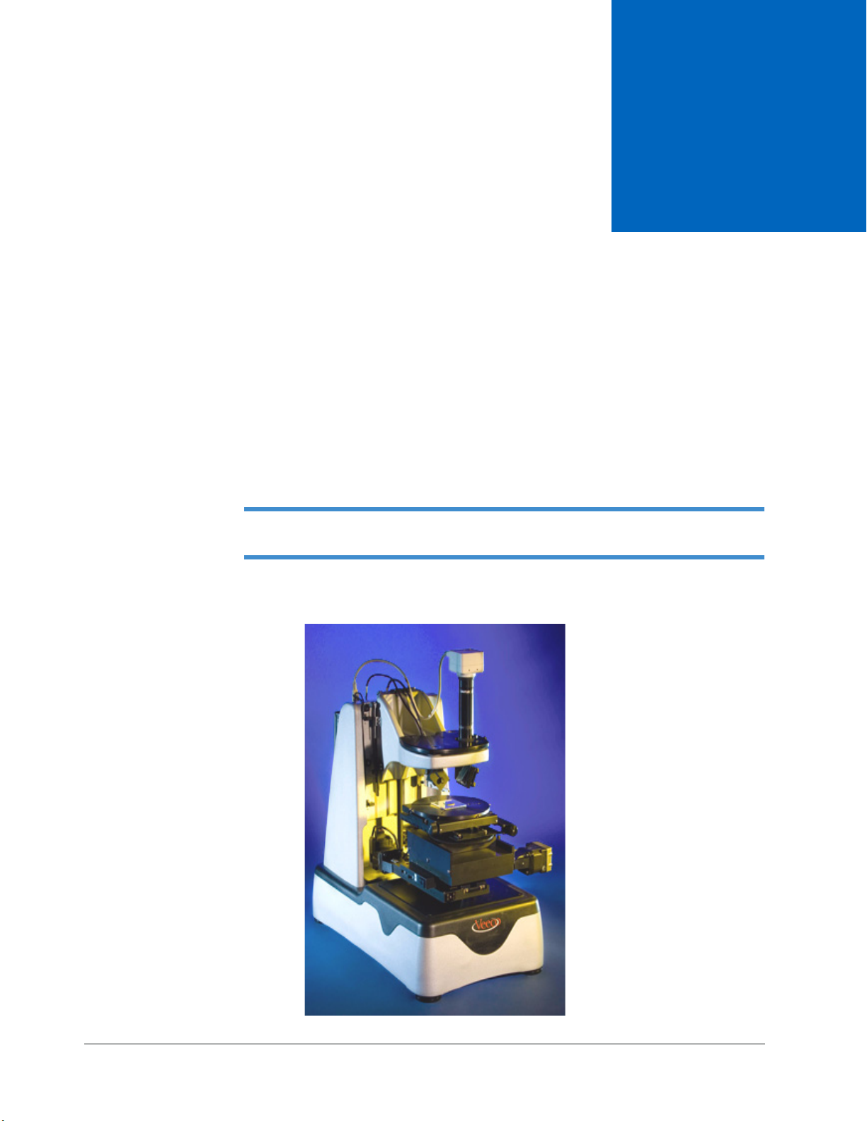
DEKTAK 150 SYSTEM OVERVIEW
The Dektak® 150 surface profiler is an advanced thin and thick film step height measurement tool
capable of measuring steps below 100Å. It also measures samples up to six inches in dimension and
up to four inches thick.
You can use the Dektak 150 to profile surface topography and waviness, as well as to measure surface
roughness in the nanometer range. The system provides a step-height repeatability of 0.6 nm (6Å.)
IMPORTANT! Environmental data sheets regarding the RoHS compliancy of the Dektak
150 system and the Dell computer that it uses appear in Appendix H of this manual.
1
Figure 1-1: The Dektak 150 Stylus Profiler
Dektak 150 System Overview 1-1

SYSTEM COMPONENTS
This section briefly describes the major components of the Dektak 150 system. For a complete listing
of components and optional accessories, see Appendix B, Technical Specifications and Purchased
Options.
System Configurations
The Dektak 150 stylus profiler comes in the following three configurations:
• The standard 2-D Dektak 150, which uses a two-axis, manual sample-positioning stage with
4 x 4-inch X-Y translation, manual leveling and manual theta (see Figure 1-2).
• The optional 3-D Mapping and Automation Packages, which use either:
• A single-axis 4-inch Y auto stage that enables the mapping of 3D images in Wyko
(see Figure 1-2).
• A 6-inch X-Y auto stage that, in addition to 3D mapping, provides automation and
programmability of up to 200 sites on samples of up to six inches in diameter.
All three configurations work with the hardware and software described in Appendix B, Technical
Specifications and Purchased Options.
®
Vision
®
NOTE – Except where otherwise noted, the instructions in this manual apply to all three
stage configurations.
Figure 1-2: Sample-Positioning Stage
Manual X-Y sample
positioning stage
Single-axis Y
auto stage (a 3D
mapping option)
1-2 Dektak 150 System Overview
Computer and Software
The computer incorporates a Celeron® or Semprom™ 2.4 GHz or faster microprocessor (optional
Pentium® 4 or Athlon™) with 1 GB of RAM and 40-GB internal drive. The computer includes a
CD-R/RW drive. With the Pentium 4 or Athlon processor, it is also comes with a 1.4-MB, 3.5” high-
density diskette drive. The computer console includes a keyboard and mouse.
®
The Microsoft
Dektak 150 Version 9 software allows you to take single- or multiple-scan measurements, calculate
analytical functions, and perform specialized operations, such as comparing analytical results from
multiple scans. For more information, see Dektak 150 Software Functions on page 1-7.
Windows® XP operating system provides a user-friendly interface. The pre-loaded
Figure 1-3: The Dektak 150 Welcome Screen
Optional Video Monitor
The optional Dektak 150 monitor provides a 17-inch, high-resolution, flat-panel color display. It
shows programs and graphics in full color, along with a color video image of the sample surface from
the USB camera in the optical assembly. The Dektak 150 software displays the substrate either alone
or with superimposed graphics.
Stylus Surface Profiler
The Dektak 150 stylus surface profiler contains all of the the mechanical, electrical and optical
components for sample placement, sample viewing, and scanning/measurement. Its cast aluminum
frame and support elements provide good repeatability with a low-noise floor. As described in
System Configurations on page 1-2, the profiler can be configured with one of two sample-
automation stages.
A diamond-tipped L stylus permits accurate two-dimensional surface profiler measurements in a
wide range of applications. In standard configuration, user-programmable stylus force from from 1
mg to 15 mg allows profiling on soft or hard surfaces. The N-Lite option enables stylus forces down
to 0.03 mg.
Dektak 150 System Overview 1-3
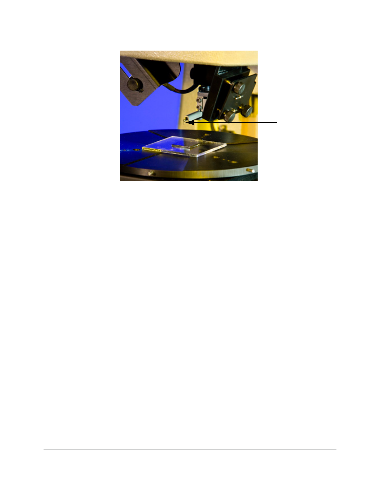
Figure 1-4: Dektak 150 Stylus
Stylus
Environmental Enclosure
The conductive acrylic environmental enclosure protects the sample and scan area from adverse
outside influences such as noise, vibrations, dust and air currents.
USB Video Camera and Optical Assembly
The standard system is equipped with an optical assembly that includes a 640 x 480-pixel (1/3inchformat) USB video camera with fixed magnification. The field of view is 166X with the 17-inch
video monitor.
The optional zoom optical assembly provides a manually adjusted 0.67-to-4.29 mm variable range.
The field of view is 644X to 100X with the 17-inch video monitor.
With both optical assemblies, the intensity illumination adjusts to view samples with differing
reflectivity. No special video card is required. However, USB camera drivers must be installed in
order for the camera to operate properly.
Manual X-Y Stage
The standard stage (shown in Figure 1-2) accommodates samples up to four-inches thick, performs
long scans of 55 millimeters, and provides
50 mm, 100 mm and 150 mm wafer alignment pins, the stage chuck provides three-point suspension
for performing stress analysis.
± 2-inch X-Y translation. In addition to 2”, 3”, 4”, 6”,
Options and Accessories
A number of options and accessories are available for the Dektak 150, including:
• A 4-inch Y auto stage that enables 3D mapping (see Figure 1-2).
• A 6-inch X-Y auto stage that, in addition to 3D mapping, provides automation and
programmability of over 200 sample sites.
1-4 Dektak 150 System Overview
• A broad line of calibration standards that calibrate the system for any application.
• A variety of styli for measuring fine surface features and softer samples.
• The N-Lite Low Force Package for using fine tips without damaging the surface.
• Extended vertical range for measuring large steps or curved surfaces.
• Scan-stitching software enables shape measurements on samples greater than 55 mm.
• Stress Measurement for calculating tensile or comprehensive stress on processed wafers.
• Wyko Vision analysis software (standard with the Y auto stage) that enables true 3D-mapping,
bearing ratio, and over 200 additional analyses.
• Cantilever deflection for accurate force-over-time measurement.
For a full list of options and accessories, see Appendix B, Technical Specifications and Purchased
Options.
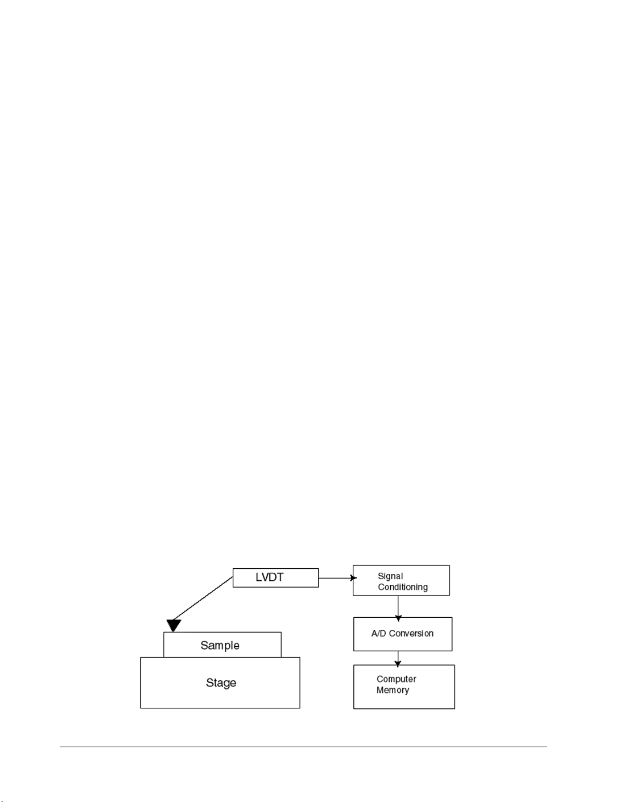
HOW THE SYSTEM WORKS
The Dektak 150 profiler takes measurements electromechanically by moving the sample beneath a
diamond-tipped stylus. The high-precision stage moves a sample beneath the stylus according to a
user-programmed scan length, speed and stylus force. The stylus is mechanically coupled to the core
of an LVDT (Linear Variable Differential Transformer).
As the stage moves the sample, the stylus rides over the sample surface. Surface variations cause the
stylus to be translated vertically. Electrical signals corresponding to stylus movement are produced as
the core position of the LVDT changes. The LVDT scales an AC reference signal proportional to the
position change, which in turn is conditioned and converted to a digital format through a high
precision, integrating, analog-to-digital converter.
The digitized signals from performing a single scan are stored in computer memory for display,
manipulation, measurement, and printing. The Dektak 150 stores programs that can easily be
changed to suit both production and laboratory use.
Figure 1-5: Block Diagram of the Dektak 150 Architecture
Dektak 150 System Overview 1-5

Sample Positioning
The two-axis manual stage and the auto stages require different sample-positioning procedures.
Two-Axis Manual Stage
After loading the sample on the stage, you coarse-position the measurement site to the center of the
crosshair using the quick-release clips. You then fine-position the scan site to the center of the
crosshairs using the fine-positioning knobs.
X-Y Auto Stage and Single-Axis Y Auto Stage
After loading the sample on the stage, you position the sample under the stylus using the icons in the
Stage Control Panel To fine-position the sample to the reticule, either enter relative moves in the
Stage Control Panel, or left-click in the Sample-Positioning window. The stage follows the
movement of the mouse.
A template in the shape or a wafer or disk appears in the Stage Control Panel. Point the mouse to the
desired location on the template, double-click the location, and the stage automatically translates to
that approximate position.
Scanning
When a scan routine begins, the stylus lowers, and the tip contacts the sample surface. As soon as the
stylus makes contact with the surface, the tower (see Figure 2-1) slows and stops when the sensor is
at the null position of the LVDT. This procedure guides the Tower Down process each time the stylus
makes contact with surface.
NOTE – If your system includes the N-Lite or 3-D Mapping option, or if the scan is set for
Hill or Valley, the Tower Down process described above is somewhat different.
The stage moves the sample as the stylus rides over the surface features. The video monitor provides
a view of both the physical scanning of the sample and the plotting of the data.
At the end of the scan, the stylus automatically retracts, the scan drive resets, and the system is
immediately ready for the next scan. The surface features encountered by the stylus are represented
as a two-dimensional profile that is plotted, scaled, and displayed on the monitor (see Data Plot
Window on page 1-8).
NOTE – When the optional Cantilever Deflection software is installed, the Dektak 150
profiler moves the stylus in a manner that produces highly accurate force-over-time
measurements. The scan drive does not move.
Profile Manipulation and Measurement
An initial scan profile may require software leveling, zero referencing and software magnification to
zoom in on an area of interest. Continuous measurement calculations are facilitated by movements of
the reference (R) and measurement (M) cursors, which can be pre-set at desired bandwidths.
1-6 Dektak 150 System Overview

Measurement Output
The Data Plot window shows the live scan data, the user-set scan parameters, and the results of the
calculations of any user-selected analytical functions, which provide detailed statistical information
about the profile data. For more information, see Analytical Functions on page 1-7 and Data Plot
Window on page 1-8.
DEKTAK 150 SOFTWARE FUNCTIONS
The Dektak 150 Version 9 software carries out all of the functions necessary to taking a single- or
multiple-scan measurement and calculating analytical functions. In addition, it performs:
• MicroForm™ adjustment, which reveals difficult shapes and overcomes steep slopes, thus
improving the accuracy of the slope calculation. The MicroForm algorithm adjusts the lateral
plot to become a function of the vertical position of the stylus, thus compensating for the arcing
motion of the stylus.
• Step detection, which automatically levels, detects and measures single or multiple steps in a
single scan. It also provides an average of all the steps.
The following sections describe some of the major functions of the Dektak 150 software.
Automation Programs
Automation Program files can store a number of scan routines on the hard disk. Scan routines, along
with their stage locations and analytical functions, are inserted into the automation program.
Automation Programs are stored for various applications in Windows file format on the hard disk,
giving the Dektak 150 virtually unlimited program storage capability.
The Automation Program Summary (APS) Report provides data in tabular form on the just-
concluded or saved automation program. In addition to showing basic information such as the
number of scan routines, this window displays the cursor locations and statistical information
regarding each analytical function (see Analytical Functions on page 1-7).
Scan Routines
A Dektak 150 scan routine consists of up to sixteen individual scan parameters that you can select
using the mouse. You can determine parameters such as scan length and speed, software leveling, and
stylus force. A maximum of 10,000 scan routines can be entered into each automation program file.
Analytical Functions
The Dektak 150 has a wide range of analytical functions available for analysis of roughness,
waviness, step height, and geometrical measurements. You can log up to 30 analytical functions per
scan to the APS.
Dektak 150 System Overview 1-7
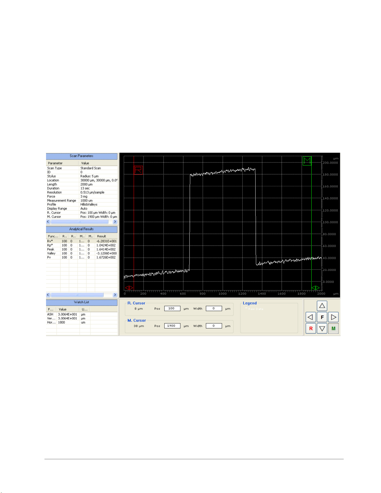
Data Plot Window
The Data Plot window shows the scan data as well as various parameters from the scan routine, such
as the stage X/Y and theta location, scan identification, scan length, scan speed, resolution, stylus
force, measurement range and profile. Also shown are the vertical and horizontal distances between
the cursor/trace intercepts, as well as the distances from the vertical and horizontal “zero” grid lines.
If you want to change the units of measure before or after the scan, you can specify angstroms, um, or
nm.
If you requested analytical functions, the results of those calculations also appear. Furthermore, the
plotting screen includes a Watch List, which serves as a real-time monitor of ASH (delta average step
height), horizontal distance and vertical distance.
Figure 1-6: Data Plot Window
1-8 Dektak 150 System Overview

DEKTAK 150 REFERENCE MATERIALS
The Dektak 150 reference materials include this manual in Adobe® Acrobat® Portable Document
Format (PDF) and any software release notices relevant to the current version of the Dektak 150
application. These electronic files, which are both pre-installed and provided on a separate CD,
provide a convenient way to quickly search for a particular subject, along with the capability to print
specific sections of this manual.
In addition, the Dektak 150 application includes some context-sensitive help.
Context-Sensitive Help
When provided, context-sensitive Help offers pop-up assistance for specific fields and controls in a
Dektak 150 dialog box.
To display the context-sensitive Help, click the question mark in the upper-right corner of a dialog
box, and then click a particular field or control. Information about that item appears in a pop-up
window.
Online Help
The online Help in the Dektak 150 application consists of this manual in PDF format. To access it,
follow the instructions in the section below.
This Manual in PDF Format
To access the PDF file of this manual, do one of the following:
• On your Windows desktop, click the shortcut labled Dektak 150 Manual.
• Select Start > All Programs > Veeco > Dektak 150 Manual.pdf.
• Within the Dektak 150 application, click Help > Contents > Dektak 150 Manual.pdf or press
the F1 key.
NOTE – Due to Veeco copyright specifications, certain editing features for the PDF files
have been disabled.
How to Use This Manual
After you have installed the Dektak 150 system according to the instructions in Chapter 2, proceed to
Chapter 3 to gain familiarity with the basic features of the software interface and perform a step-by-
step exercise that teaches you how to load, position, and unload a sample.
The Chapter 3 exercise is continued in Chapter 4, which teaches single-scan operation, and Chapter
5, which tells you how to take a multiple-scan measurement. After you have performed the complete
set of exercises, you will have learned the basic skills required to program and run single and multiple
scan routines.
Dektak 150 System Overview 1-9

Once you have mastered the basics, you can proceed to Chapter 6, which explains the many
analytical functions that perform complex computations on the profile data. To learn how to
customize your scan routines to fit your application, go to Chapter 7, which describes scan
parameters, data parameters, and display parameters.
Chapter 8 provides a detailed description of every menu and toolbar in the Dektak 150 user interface,
while Chapter 9 tells you how to calibrate and maintain your system.
The first two appendices contain facilities specifications, technical specifications, and a list of
available purchased options. The appendices that follow them provide instructions for using
specialized functions of the software.
Whether you actually perform the hands-on exercises or simply read them for information, this
manual provides all the instructions that you need to effectively operate the Dektak 150 stylus surface
profiler.
1-10 Dektak 150 System Overview
INSTALLING THE DEKTAK 150 SYSTEM
This chapter tells you how to install the Dektak 150 surface profiler and verify that the system is
functioning correctly. If you encounter problems, call Dektak 150 Technical Support at 520-741-
1044, extension 1220.
SAFETY PRECAUTIONS
Use Dektak 150 equipment only as specified in this manual and as specified in any
documentation associated with its components. Any use of the equipment in an unspecified
manner is strongly discouraged and may result in damage or injury as cautioned by signed
warnings in this chapter and throughout the documentation.
2
Table 2-1: Safety Symbols Key
Symbol Definition
This symbol identifies conditions or practices that could result in
damage to the equipment or other property, and in extreme cases,
possible personal injury.
Ce symbole indique des conditions d'emploi ou des actions pouvant
endommager les équipements ou accessoires, et qui, dans les cas
extrêmes, peuvent conduire à des dommages corporels.
Dieses Symbol beschreibt Zustände oder Handlungen die das Gerät
oder andere Gegenstände beschädigen können und in Extremfällen
zu Verletzungen führen können.
This symbol identifies conditions or practices that involve potential
electric shock hazard.
Ce symbole indique des conditions d'emploi ou des actions comportant un risque de choc électrique.
Dieses Symbol beschreibt Zustaende oder Handlungen die einen
elekrischen Schock verursachen koennen.
Installing the Dektak 150 System 2-1
CAUTION: Only qualified personnel aware of the hazards involved may
perform service and adjustments.
ATTENTION: Toute réparation ou étalonnage doit être effectué par des personnes
qualifiées et conscientes des dangers potentiels.
VORSICHT: Service- und Einstellarbeiten sollten nur von qualifizierten
Personen, die sich der auftretenden Gefahren bewußt sind,
durchgeführt werden.
CAUTION: Follow company and government safety regulations. Keep
unauthorized personnel out of the area when working on
equipment.
ATTENTION: Il est impératif de suivre les prérogatives imposées tant au niveau
gouvernemental qu’au niveau des entreprises. Les personnes non
autorisées ne peuvent rester près du système lorsque celui-ci
fonctionne.
VORSICHT: Befolgen Sie die gesetzlichen Sicherheitsbestimmungen Ihres
Landes. Halten Sie nicht authorisierte Personen während des
Betriebs fern vom Gerät.
CAUTION: Voltages supplied to and within certain areas of the system are
potentially dangerous and can cause injury to personnel. Powerdown everything and unplug from sources of power before doing
ANY electrical servicing. (Veeco personnel only.)
ATTENTION: Les tensions utilisées dans le système sont potentiellement
dangereuses et peuvent blesser les utilisateurs. Avant toute
intervention électrique, ne pas oublier de débrancher le système.
(Réservé au personnel de Veeco Instruments, Inc. seulement.)
VORSICHT: Die elektrischen Spannungen, die dem System zugeführt werden,
sowie Spannungen im System selbst sind potentiell gefährlich und
können zu Verletzungen von Personen führen. Bevor elektrische
Servicearbeiten irgendwelcher Art durchgeführt werden ist das
System auszuschalten und vom Netz zu trennen. (Veeco Personal.)
2-2 Installing the Dektak 150 System
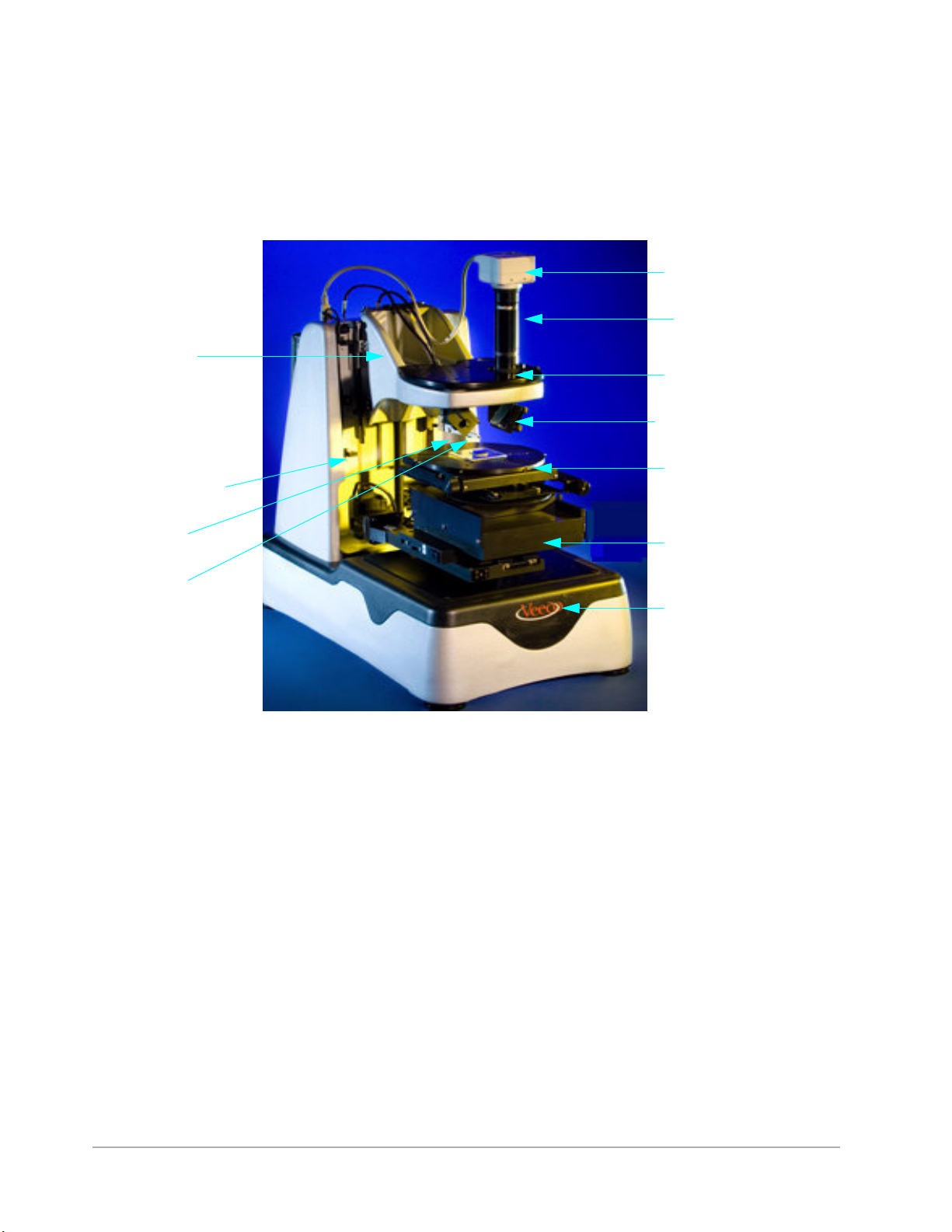
PROFILER COMPONENTS
Figure 2-1 shows the main components of the front of the Dektak 150 surface profiler. Figure 2-2 shows
the main components of the back. Refer to these figures as you install the system.
Figure 2-1: Major Components of the Dektak 150 Surface Profiler
Camera
Camera
Optical assembly
Tow er
Z-axis limit
switch rack
Sensor
Stylus
Optics mounting plate
Mirror
Mirror
Manual X-Y stage
(sample-positioning
stage)
Scan block
Base
Installing the Dektak 150 System 2-3
 Loading...