

Page 1

WLX-2007
For FCC Certification Testing
WLX-2007 User Guide
Document Number: E-PR-2006-0162
Version: 0.3
Author: Jerod Meacham
Page 2

Revision History
Date Revision Description
11/2/06 0.3 Initial release.
© 2006 Staccato Communications, Inc. All rights reserved.
Information provided in this document is provided in connection with Staccato products. All information contained in this document is
subject to change without notice. Nothing in this document shall operate as an express or implied license or indemnity under the intellectual property rights of Staccato or third parties. Except as provided in Staccato’s Terms and Conditions of Sale for such products,
Staccato assumes no liability whatsoever, and Staccato disclaims any express or implied warranty, relating to sale and/or use of Staccato products including liability or warranties relating for a particular purpose, merchantability, or infringement of any patent, copyright
or other intellectual property right.
Staccato’s products are not authorized for use in life-support or safety critical applications. Use in such applications is done at the sole
discretion of the customer. Staccato will not warrant the use of its devices in such applications.
While the information contained herein is believed to be accurate, such information is preliminary, and should not be relied upon for
accuracy or completeness, and no representations or warranties of accuracy or completeness are made.
THE INFORMATION CONTAINED IN THIS DOCUMENT IS PROVIDED ON AN “AS IS” BASIS. In no event shall Staccato be liable
for damages arising directly or indirectly from any use of the information contained in this document.
All trademarks listed in this document are the property of their respective holders.
Contact your Staccato sales representative to obtain the latest specifications before placing your product order.
Staccato Communications, Inc.
6195 Lusk Boulevard, Suite 200
San Diego, CA 92121
Phone: 858.812.1000
Fax: 858.812.1001
www.staccatocommunications.com
Regulatory Notices
This device complies with Part 15 of the FCC Rules. Operation is subject to the following two conditions:
(1) this device may not cause harmful interference, and (2) this device must accept any interference
received, including interference that may cause undesired operation.
THIS DEVICE MUST BE INSTALLED IN A LOCATION THAT IS NOT ACCESSIBLE TO THE GENERAL PUBLIC. INSTALL THE
DEVICE SO THAT THE ANTENNA IS MORE THAN 20 CM FROM UNSUSPECTING PERSONNEL. FAILURE TO INSTALL
THIS DEVICE AS DESCRIBED WILL RESULT IN A FAILURE TO COMPLY WITH FCC RULES FOR RF EXPOSURE AND IS
DISCOURAGED. ONLY ANTENNAS APPROVED WITH THE DEVICE MAY BE USED. THIS DEVICE MAY NOT BE CO-
LOCATED WITH OTHER TRANSMITTERS WITHOUT FURTHER APPROVAL BY THE FCC.
The device is compliant with 47 CFR 15.519(a)(1):
"A UWB device operating under the provisions of this section shall transmit only when it is sending information to an associated
receiver. The UWB intentional radiator shall cease transmission within 10 seconds unless it receives an acknowledgement from the
associated receiver that its transmission is being received. An acknowledgement of reception must continue to be received by the
UWB intentional radiator at least every 10 seconds or the UWB device must cease transmitting."
Note: Any intentional or unintentional modifications not expressly approved by Staccato Communications or the FCC will void the
warranty of the device and the authority of the user to operate the device.
Page 3

Contents
1.0 Introduction ........................................................................................................... 1
1.1 Purpose........................................................................................................... 1
1.2 Intended Audience .......................................................................................... 1
1.3 Conventions .................................................................................................... 1
1.4 Document Structure and Use.......................................................................... 1
1.5 Technical Support ........................................................................................... 1
2.0 Overview ................................................................................................................ 2
2.1 System Requirements..................................................................................... 3
3.0 Installation ............................................................................................................. 4
3.1 Software Installation........................................................................................ 4
3.2 Hardware/Driver Installation............................................................................ 9
4.0 Operation ............................................................................................................. 14
Acronyms and Definitions.................................................................................. 17
Document References ........................................................................................ 18
Contact Information ............................................................................................ 19
WLX-2007 User Guide Page i
Doc. No. E-PR-2006-0162 v0.3 Staccato Communications
Page 4

List of Figures
Figure 2-1 WLX-2007 .................................................................................................. 2
Figure 2-2 WLX-2007 Back ......................................................................................... 3
Figure 3-1 Staccato_FCC.exe ..................................................................................... 4
Figure 3-2 .Net Framework Installation ....................................................................... 4
Figure 3-3 .Net Framework Installation ....................................................................... 5
Figure 3-4 .Net Framework License Agreement .......................................................... 5
Figure 3-5 .Net Framework Setup Complete ............................................................... 6
Figure 3-6 Staccato FFC Installer ................................................................................ 6
Figure 3-7 Staccato FFC Installer ................................................................................ 7
Figure 3-8 Staccato FFC Installer Warning ................................................................. 7
Figure 3-9 Staccato FFC Installer Warning ................................................................. 8
Figure 3-10 Staccato FFC Installer Finished ................................................................. 8
Figure 3-11 WLX-2007 USB Mini-B Connector ............................................................. 9
Figure 3-12 Found New Hardware Wizard .................................................................. 10
Figure 3-13 Found New Hardware Wizard .................................................................. 10
Figure 3-14 Found New Hardware Wizard .................................................................. 11
Figure 3-15 Found New Hardware Wizard .................................................................. 11
Figure 3-16 Found New Hardware Wizard .................................................................. 12
Figure 3-17 Found New Hardware Wizard .................................................................. 12
Figure 3-18 Found New Hardware Wizard .................................................................. 13
Figure 3-19 Found New Hardware Wizard Finished ................................................... 13
Figure 4-1 Start Menu ................................................................................................ 14
Figure 4-1 WLX-2007 Config Screen ........................................................................ 15
WLX-2007 User Guide Page ii
Doc. No. E-PR-2006-0162 v0.3 Staccato Communications
Page 5

1.0 Introduction
1.1 Purpose
This guide functions as a user guide for the installation and operation of the WLX-2007 with
regards to FCC certification testing.
1.2 Intended Audience
This reference is intended for technicians or engineers working with the WLX-2007.
1.3 Conventions
The following conventions are used throughout this document.
z Blue text indicates a link that can be clicked on when viewing the electronic Portable Doc-
ument Format (PDF) version of this manual. The PDF version is formatted for use using
Adobe Acrobat version 4.0 or above. A free viewer can be downloaded from the Adobe
website at http://www.adobe.com.
Note:
Notes provide extra information on a subject or give specific tips.
Caution:
Cautions provide information to the reader about possible situations that
could result in damage to equipment or loss of data.
1.4 Document Structure and Use
The organization of this reference guide is optimized for finding appropriate information
quickly.
z Section 1 provides an introduction of this document
z Section 2 provides an overview of the WLX-2007
z Section 3 provides an installation guide
z Section 4 provides an operation guide
A list of acronyms used, document references, and contact information are provided at the end
of this document.
1.5 Technical Support
Staccato Communications provides a support team to help debug any issues that may arise
including any deviations from the installation or operation of the WLX-2007 as listed in this
document.
For assistance, please e-mail support@staccatocommunications.com
and ask to be transferred to the Solutions Delivery team.
or call 1-858-812-1000
WLX-2007 User Guide Page 1
Doc. No. E-PR-2006-0162 v0.3 Staccato Communications
Page 6

2.0 Overview
The WLX-2007 Certified Wireless USB DWA Hub provides a 4-port hub connected to a device
wire adapter for use with legacy USB products. The Hub is intended to be wirelessly connected to an HWA or embedded Certified Wireless USB host to function correctly.
The WLX-2007 includes the following features:
z Fully integrated, single-chip all CMOS ultra-wideband solution compliant with Certified
Wireless USB as defined by the USB implementers Forum, WiMedia PHY specification
V1.1 and WiMedia MAC specification v1.0.
z Support for all Wireless USB mandatory and optional datarate modes including 53.3, 80,
106.7, 160, 200, 320, 400, and 480 Mbps
z Integrated 4-port Hub
z Low power consumption
z Small form factor
z Integrated antenna
Figure 2-1 shows a photo of the WLX-2007.
Figure 2-1 WLX-2007
WLX-2007 User Guide Page 2
Doc. No. E-PR-2006-0162 v0.3 Staccato Communications
Page 7
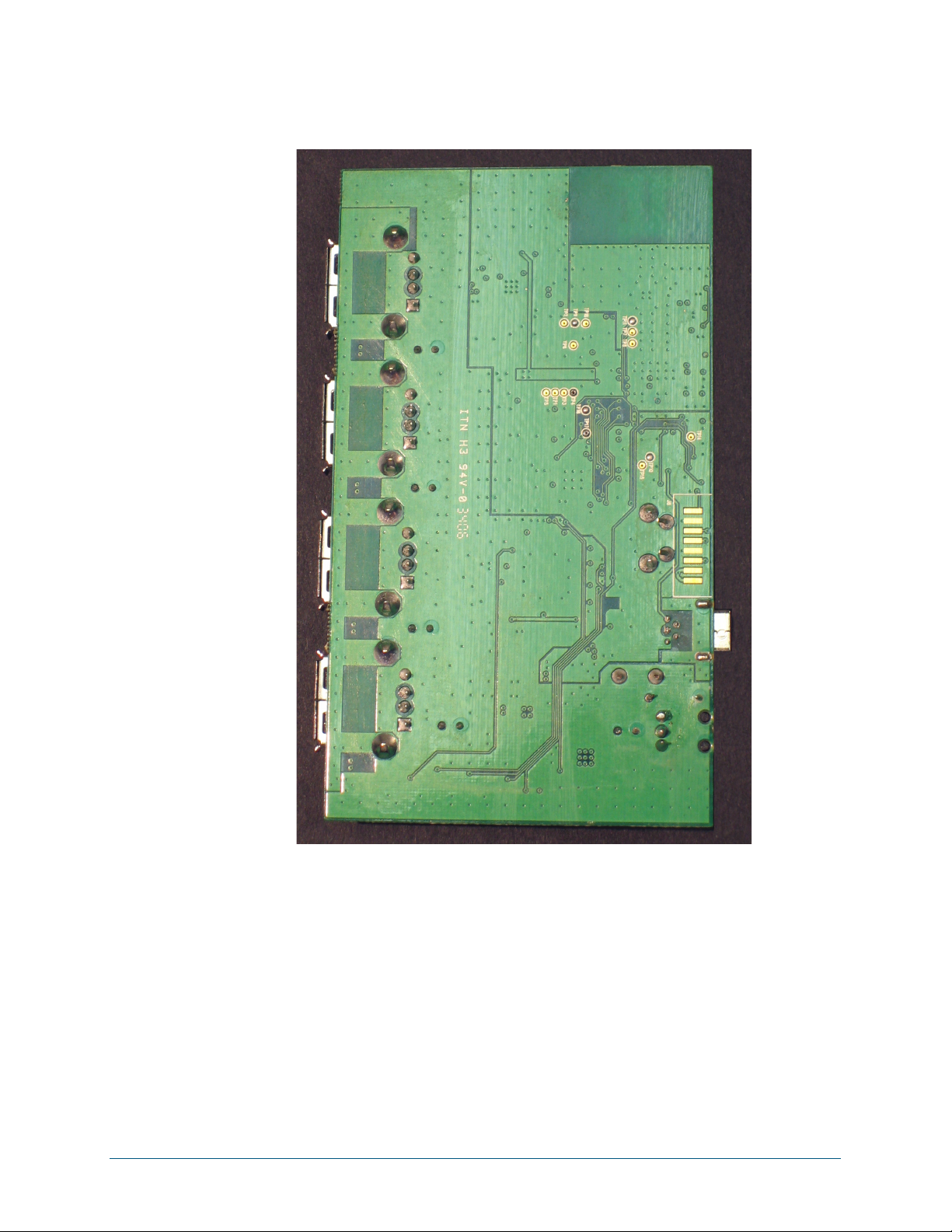
Figure 2-2 shows the back of the WLX-2007.
Overview
Figure 2-2 WLX-2007 Back
2.1 System Requirements
The WLX-2007 software requires a computer system that meets the following minimum
requirements:
z 1 GHz PC
z Windows XP operating system with SP2 (service pack 2) installed
z One available USB 2.0 port
WLX-2007 User Guide Page 3
Doc. No. E-PR-2006-0162 v0.3 Staccato Communications
Page 8

3.0 Installation
The following steps are required for installation of the software associated with the WLX-2007.
3.1 Software Installation
Locate the "Staccato_FCC.exe" installer and double click. This will initiate the installation process. See Figure 3-1 below.
Figure 3-1 Staccato_FCC.exe
Depending on the software installed on the PC used, Microsoft .Net framework may need to
be installed. The installer will prompt the user for this installation. Click "Yes" to continue. See
Figure 3-2 below.
Figure 3-2 .Net Framework Installation
WLX-2007 User Guide Page 4
Doc. No. E-PR-2006-0162 v0.3 Staccato Communications
Page 9

Installation
The .NET framework installer will open and guide the user through the installation process.
Click "next" to begin the installation of .NET framework. See Figure 3-3 below.
Figure 3-3 .Net Framework Installation
In order to install Microsoft .NET framework, the End-User license agreement must be
accepted. Click the checkbox to accept the license agreement and click the "Install>" button
to continue. See Figure 3-4 below.
Figure 3-4 .Net Framework License Agreement
WLX-2007 User Guide Page 5
Doc. No. E-PR-2006-0162 v0.3 Staccato Communications
Page 10

Installation
Once the installation of the .NET framework is complete the image will look like Figure 3-5
shwon below. Click "Finish" to close the .NET installer and return to the Staccato Communications installer to continue the installation process.
Figure 3-5 .Net Framework Setup Complete
The Staccato FCC Installer will now load. Click "Next" to continue. See Figure 3-6 below.
Figure 3-6 Staccato FFC Installer
Page 6 WLX-2007 User Guide
Staccato Communications Doc. No. E-PR-2006-0162 v0.3
Page 11

Installation
Once prompted, click the "Install" button to begin the installation process. See Figure 3-7
below.
Figure 3-7 Staccato FFC Installer
Currently Microsoft does not have testing facilities in place for Wireless USB drivers. As such,
a warning message will appear warning the user that the driver has not undergone Windows
Logo testing. Click "Continue Anyway" to continue the installation. See Figure 3-8 below.
Figure 3-8 Staccato FFC Installer Warning
WLX-2007 User Guide Page 7
Doc. No. E-PR-2006-0162 v0.3 Staccato Communications
Page 12

Installation
A second driver must be loaded in order for the software to function and as such, another
warning will appear. Like before, click "Continue Anyway" to continue the installation. See Fig-
ure 3-9 below.
Figure 3-9 Staccato FFC Installer Warning
Once the installer has completed, the following window will be shown. Click "Finish" to close
the installer. At this point an icon will be placed on the desktop and in the start menu under the
"Staccato FCC" folder. See Figure 3-10 below.
Figure 3-10 Staccato FFC Installer Finished
Page 8 WLX-2007 User Guide
Staccato Communications Doc. No. E-PR-2006-0162 v0.3
Page 13

3.2 Hardware/Driver Installation
Power the WLX-2007 using the provided power adapter.
Using a USB A to mini-B cable, attach the mini-B side of the cable into the mini-B port on the
WLX-2007 as shown in Figure 3-11 below. Attach the A side of the cable to the host PC.
Installation
Figure 3-11 WLX-2007 USB Mini-B Connector
WLX-2007 User Guide Page 9
Doc. No. E-PR-2006-0162 v0.3 Staccato Communications
Page 14

Installation
Windows will detect new hardware. There are two drivers that need to be loaded for the WLX-
2007. The first of the two drivers is called the "Staccato Wireless USB Host Wire Adapter".
When the found new hardware wizard is shown, select "No, not this time" in response to connecting to windows update then click "Next". See Figure 3-12 below.
Figure 3-12 Found New Hardware Wizard
Choose to install the software automatically and click next.See Figure 3-13 below.
Figure 3-13 Found New Hardware Wizard
Page 10 WLX-2007 User Guide
Staccato Communications Doc. No. E-PR-2006-0162 v0.3
Page 15

Installation
Currently there is no driver testing available for wireless USB drivers which results in the following error message. Click "Continue Anyway" to continue. See Figure 3-14 below.
Figure 3-14 Found New Hardware Wizard
At this point, the Staccato Wireless USB Host Wire Adapter should be installed. Click "Finish"
to install the second driver. See Figure 3-15 below.
Figure 3-15 Found New Hardware Wizard
WLX-2007 User Guide Page 11
Doc. No. E-PR-2006-0162 v0.3 Staccato Communications
Page 16

Installation
After the Staccato Wireless USB Host Wire Adapter driver is installed, windows will detect the
second driver required. This driver is called Staccato Wireless USB Radio Control. If asked to
connect to windows update to search for software select "No, not this time" and click next. See
Figure 3-16 below.
Figure 3-16 Found New Hardware Wizard
Choose to install the software automatically and click next. See Figure 3-17 below.
Figure 3-17 Found New Hardware Wizard
Page 12 WLX-2007 User Guide
Staccato Communications Doc. No. E-PR-2006-0162 v0.3
Page 17

Installation
Currently there is no driver testing available for wireless USB drivers which results in the following error message. Click "Continue Anyway" to continue. See Figure 3-18 below.
Figure 3-18 Found New Hardware Wizard
At this point, the Staccato Wireless USB Radio Control driver should be installed. Click "Finish" to complete the process. See Figure 3-19 below.
Figure 3-19 Found New Hardware Wizard Finished
WLX-2007 User Guide Page 13
Doc. No. E-PR-2006-0162 v0.3 Staccato Communications
Page 18

4.0 Operation
Prior to operation, the WLX-2007 should be powered and connected via USB cable to the PC.
Ensure that the "Staccato Wireless USB Host Wire Adapter" and "Staccato Wireless USB
Radio Control" drivers are properly loaded. These drivers are visible in the Windows Device
Manager under "Universal Serial Bus Controllers" when viewing in "Devices by type" mode
selected from the "View" dropdown menu.
In order to start the graphical user interface to control the operation of the WLX-2007, double
click on the "Ripcord Diag FCC" icon on the desktop. Alternatively, Ripcord Diag FCC can be
selected from the start menu. It is located in the "Staccato FCC" folder as shown in Figure 4-1
below.
Figure 4-1 Start Menu
WLX-2007 User Guide Page 14
Doc. No. E-PR-2006-0162 v0.3 Staccato Communications
Page 19

Operation
Once the graphical user interface has loaded, the screen shown in Figure
4-1 will be available to control the WLX-2007 in various test modes.
Initially, click on "Tune PLLs." Next, click "Check PLLs". This will check to
see that the PLLs are locked and tuned correctly. If the PLLs are locked,
the messages "PLL1 Locked" and "PLL2 Locked" will appear below the
"Check PLLs" button.
After the PLLs have been tuned, the desired operational mode can be set.
By default, the system should be in "Ready" mode at startup. Standby
mode will put the system in a mode where it will not be capable of transmission, as such Ready mode is required to be set during transmit
Similarly, either 53.3 Mbps or 480 Mbps mode may be selected for any
specific test. By default, 53.3 Mbps mode is used.
The buttons for "Restart", "Phy Reset", and "Restart and Init PHY" can be
used to set the silicon into the modes specified. However, for ease of use
and test repeatability it is recommended to close the FCC test application,
remove the USB cable from the device, re-attach the USB cable and reenumerate the WLX-2007, and start the operation process from the
beginning.
The "Get Temp" button, "Read" button, "Write" button, and the two text
fields for Register Address and Register Data are used for internal debug
purposes and should not be used during any tests.
Figure 4-1 WLX-2007 Config Screen
WLX-2007 User Guide Page 15
Doc. No. E-PR-2006-0162 v0.3 Staccato Communications
Page 20

Operation
Page 16 WLX-2007 User Guide
Staccato Communications Doc. No. E-PR-2006-0162 v0.3
Page 21

Acronyms and Definitions
RF Radio Frequency
SiP System-in-Package
USB Universal Serial Bus
UWB Ultrawideband
WiMedia Standards group for Ultrawideband
W-USB Wireless Universal Serial Bus
WLX-2007 User Guide Page 17
Doc. No. E-PR-2006-0162 v0.3 Staccato Communications
Page 22

Document References
Document References
[1] MultiBand OFDM Physical Layer Specification, WiMedia Alliance, Release 1.1, July 14, 2005
[2] Wireless Universal Serial Bus Specification, Agere, Hewlett-Packard, Intel, Microsoft, NEC,
Philips, Samsung, Revision 1.0, May 12, 2005
[3] Distributed Medium Access Control (MAC) For Wireless Networks, WiMedia Technical Specifi-
cation, WiMedia Draft MAC Version 0.98.9, October 3, 2005
[4] Universal Serial Bus Specification, Compaq, Hewlett-Packard, Intel, Lucent, Microsoft, NEC,
Philips, Revision 2.0 April 27, 2000
[5] SC3501P SiP Datasheet, Staccato Communications
[6] SC3502P SiP Datasheet, Staccato Communications
Page 18 WLX-2007 User Guide
Staccato Communications Doc. No. E-PR-2006-0162 v0.3
Page 23

Contact Information
North America, Europe, Asia:
6195 Lusk Boulevard, Suite 200
San Diego, CA 92121
Phone: 1-858-812-1000
Fax: 1-858-812-1001
sales@staccatocommunications.com
support@staccatocommunications.com
Japan:
Shibuya Mark City W22F
1-12-1 Dougenzaka, Shibuya-ku
Tokyo, Japan 150-0043
Phone: +81-3-4360-5358
Fax: +81-3-4360-5301
sales@staccatocommunications.com
support@staccatocommunications.com
Page 24

© 2006 Specifications subject to change without notice. All rights reserved.
Staccato Communications
6195 Lusk Boulevard, Suite 200
San Diego, CA 92121
Phone: 1.858.812.1000 Fax: 1.858.812.1001
www.staccatocommunications.com
 Loading...