

Page 1
EasyVR 3
User Manual
1.0.11
www.veear.eu
Release
Page 2

www.veear.eu
Table of Contents
EasyVR 3 Module ............................................................................................................................................. 5
Product Description ........................................................................................................................................ 5
EasyVR 3 Features .................................................................................................................................... 5
Technical specifications ................................................................................................................................. 6
Pin assignment .......................................................................................................................................... 7
Settings and indicators .............................................................................................................................. 8
Physical dimensions .................................................................................................................................. 8
Recommended Operating Conditions ....................................................................................................... 9
Power Supply Requirements ..................................................................................................................... 9
Electrical Characteristics ........................................................................................................................... 9
Serial Interface ......................................................................................................................................... 10
Microphone .............................................................................................................................................. 11
Audio Output ............................................................................................................................................ 13
General Purpose I/O ................................................................................................................................ 14
Flash Update ........................................................................................................................................... 15
Quick start for using the module .................................................................................................................. 16
EasyVR 3 as a Development Board ........................................................................................................ 16
EasyVR Shield 3 for Arduino ........................................................................................................................ 18
Product description ...................................................................................................................................... 18
EasyVR Shield 3 Features ....................................................................................................................... 18
Technical specifications ............................................................................................................................... 19
Board overview ........................................................................................................................................ 19
Pin assignment ........................................................................................................................................ 20
Mode Jumper settings ............................................................................................................................. 20
Software Serial Pins settings ................................................................................................................... 21
Quick start guide for using the Shield .......................................................................................................... 22
With Arduino Leonardo – Due (Native USB) ........................................................................................... 22
With Arduino 2009 – Uno – Mega ........................................................................................................... 23
EasyVR Programming ................................................................................................................................... 24
Communication Protocol .............................................................................................................................. 24
Introduction .............................................................................................................................................. 24
Arguments Mapping ................................................................................................................................. 25
Command Details .................................................................................................................................... 26
Status Details ........................................................................................................................................... 31
Communication Examples ........................................................................................................................... 34
Recommended wake up procedure ......................................................................................................... 34
Recommended setup procedure ............................................................................................................. 34
Recognition of a built-in or custom SI command ..................................................................................... 35
Adding a new SD command .................................................................................................................... 35
Training an SD command ........................................................................................................................ 36
Recognition of an SD command .............................................................................................................. 36
Read used command groups................................................................................................................... 37
Read how many commands in a group ................................................................................................... 37
Read a user defined command group ..................................................................................................... 37
Use general purpose I/O pins .................................................................................................................. 38
2 EasyVR 3 User Manual (1.0.11)
Page 3

www.veear.eu
Use custom sound playback .................................................................................................................... 38
Read sound table ..................................................................................................................................... 38
Built-in Command Sets ................................................................................................................................ 39
Error codes ................................................................................................................................................... 40
Protocol header file ...................................................................................................................................... 41
EasyVR Arduino Library ............................................................................................................................... 42
EasyVR library settings ................................................................................................................................ 42
Macros ..................................................................................................................................................... 42
Detailed Description ................................................................................................................................. 42
Macro Definition Documentation ............................................................................................................. 42
EasyVR Class Reference............................................................................................................................. 42
Public Types ............................................................................................................................................ 42
Public Member Functions ........................................................................................................................ 43
Detailed Description ................................................................................................................................. 44
Member Enumeration Documentation ..................................................................................................... 44
Constructor & Destructor Documentation ................................................................................................ 47
Member Function Documentation ........................................................................................................... 48
EasyVR Commander ..................................................................................................................................... 57
Getting Started ............................................................................................................................................. 57
Speech Recognition ..................................................................................................................................... 58
Recognition Settings .................................................................................................................................... 60
Phone Tones Generation (DTMF) ............................................................................................................... 61
Testing SonicNetTM ...................................................................................................................................... 61
Using Custom Data ...................................................................................................................................... 63
Sound Table ............................................................................................................................................ 63
Speaker Independent Custom Vocabularies ........................................................................................... 64
Updating Custom Data ............................................................................................................................ 65
Updating Firmware ....................................................................................................................................... 67
QuickUSB Adapter Cable .............................................................................................................................. 68
Product Description ...................................................................................................................................... 68
QuickUSB Features ................................................................................................................................. 68
Technical Specifications............................................................................................................................... 68
Drawings and Schematics ....................................................................................................................... 68
Pin Description ......................................................................................................................................... 68
Operating Conditions ............................................................................................................................... 69
Electrical Characteristics ......................................................................................................................... 69
QuickStart Instructions ................................................................................................................................. 69
Software Setup ........................................................................................................................................ 69
Using the Adapter .................................................................................................................................... 69
How to get support ........................................................................................................................................ 70
User Manual (1.0.11) EasyVR 3 3
Page 4

www.veear.eu
Revision
Date
Description
1.0
2015/01/27
Initial draft
1.0.3
2015/02/09
New drawings and updated descriptions
1.0.4
2015/03/19
Added new pictures and minor updates
1.0.5
2015/03/25
Update pictures and quickstart sections
1.0.6
2015/03/30
Added programming and library chapters
Added PC software description
Updated pictures and layout
1.0.7
2015/03/31
Minor corrections
1.0.8
2015/04/01
Updated custom data screenshots and description
1.0.9
2015/04/02
Added chapter for QuickUSB adapter
1.0.10
2015/04/22
Updated mechanical drawing of module
1.0.11
2015/06/05
Added note about soldering headers
Removed old logo from drawings
Document History Information
4 EasyVR 3 User Manual (1.0.11)
Page 5
www.veear.eu
1
2
EasyVR 3 Module
Product Description
EasyVR 3 is a multi-purpose speech recognition module designed to
easily add versatile, robust and cost effective speech recognition
capabilities to almost any application.
The EasyVR 3 module can be used with any host with an UART
interface powered at 3.3V – 5V, such as PIC and Arduino boards.
Some application examples include home automation, such as voice
controlled light switches, locks, curtains or kitchen appliances, or
adding “hearing” to the most popular robots on the market.
It can be easily plugged into a solder-less breadboard or standard
prototyping board, and it is compatible with the mikroBUS™
specifications (see www.mikroe.com/mikrobus).
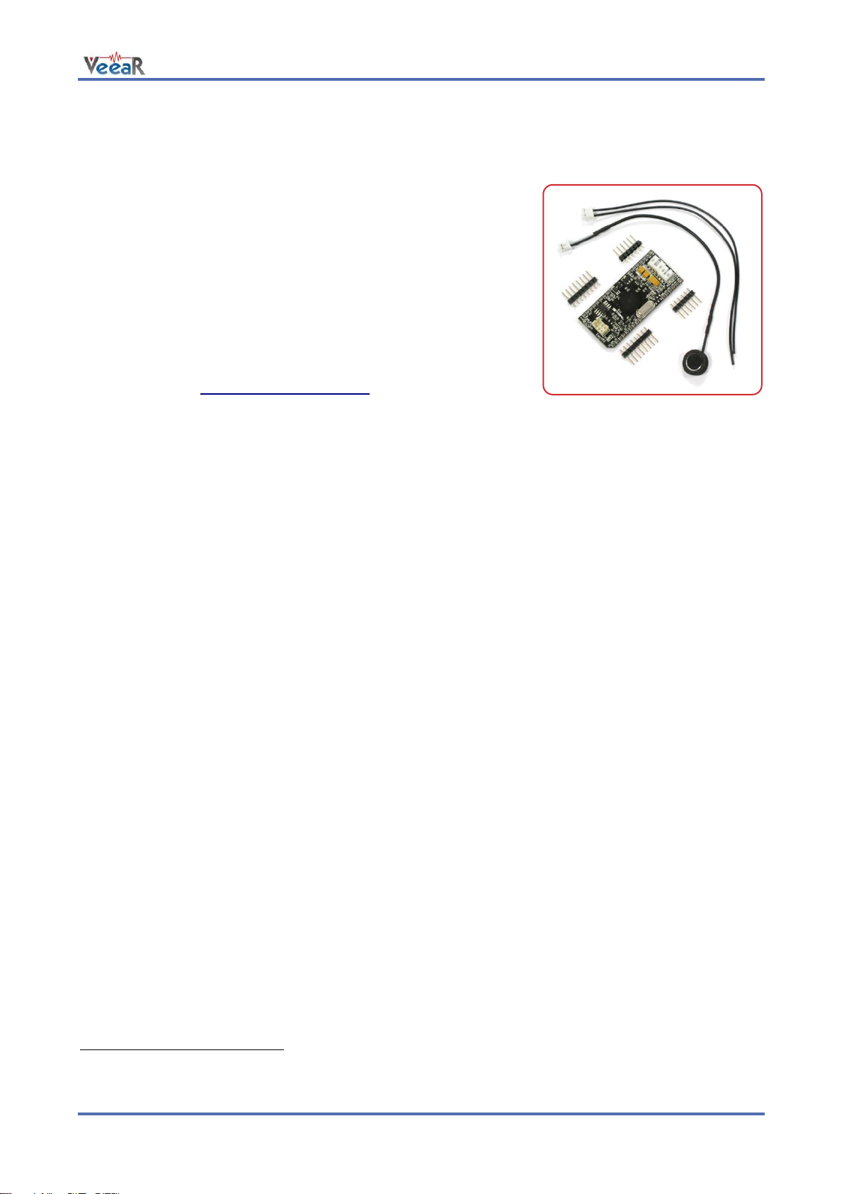
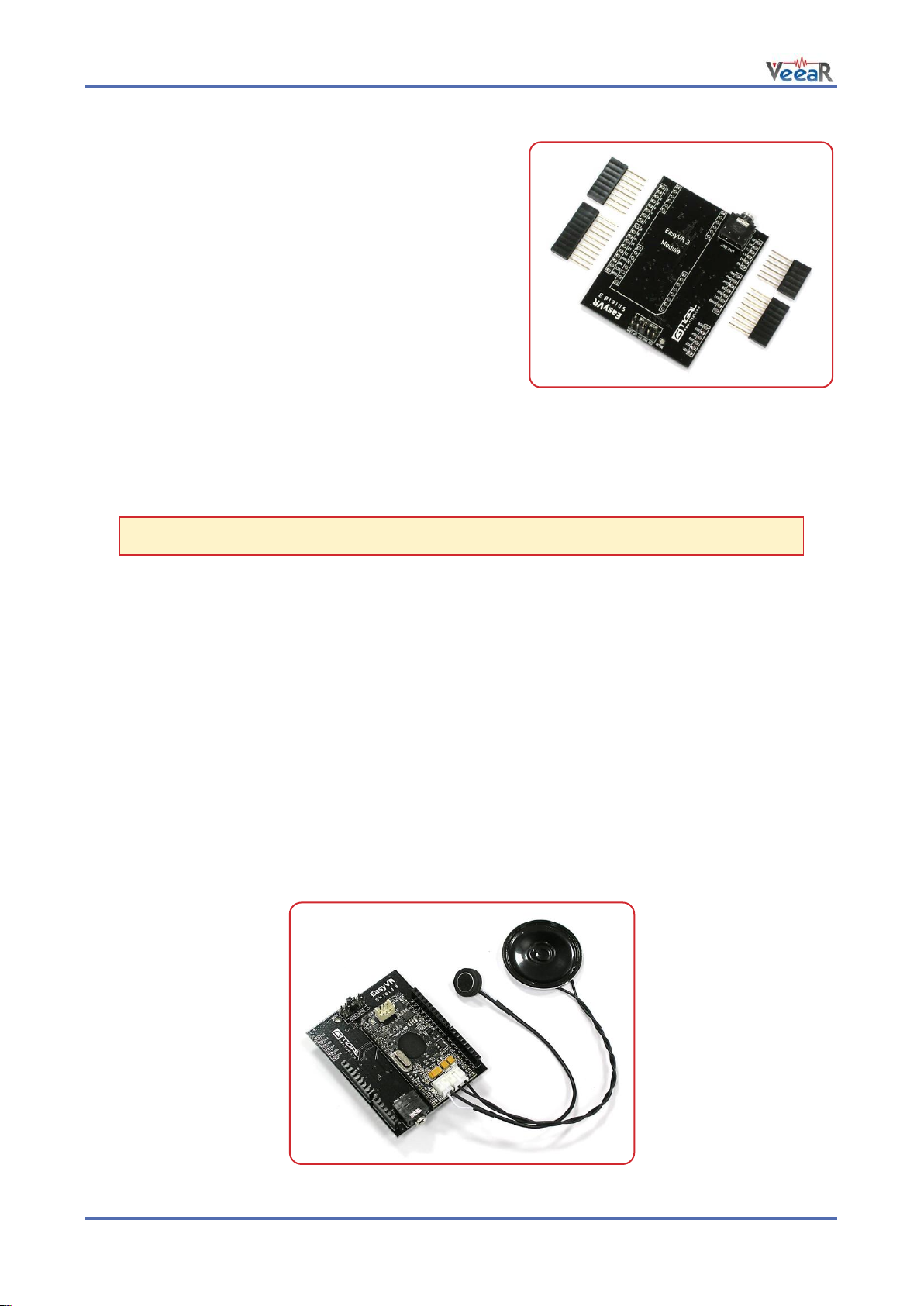
Separate male headers are provided inside the package, along with a microphone cable assembly and
speaker wires (loudspeaker not included).
EasyVR 3 Features
Up to 28 custom Speaker Independent (SI) command vocabularies1.
Supported Languages:
o US English
o British English
o French
o German
o Italian
o Japanese
o Korean
o Mandarin
o Spanish
Up to 32 user-defined Speaker Dependent (SD) or Speaker Verification (SV) commands, that can be
trained in ANY language.
A selection of built-in Speaker Independent (SI) commands for ready-to-run basic controls, in the
following languages:
o English (US)
o Italian
o German
o French
o Spanish
o Japanese
SonicNet technology for wireless communications between modules or any other sound source
(Audio CD, DVD, MP3 Player).
Up to 22 minutes of pre-recorded sounds or speech2.
DTMF tone generation.
Differential audio output that directly supports 8Ω speakers.
Easy-to-use Graphical User Interface to program Voice Commands and audio.
Standard UART interface (powered at 3.3V - 5V).
Simple and robust documented serial protocol to access and program through the host board.
6 General purpose I/O lines that can be controlled via UART commands.
A QuickT2SI™ Lite license (sold separately) is required to enable creation of Speaker Independent
vocabularies (maximum 12 commands per set).
At maximum compression rate.
User Manual (1.0.11) EasyVR 3 5
Page 6
www.veear.eu
CABLES
MISC
SPEAKER
MIC
R4
D2
GPIO
IO1
SP+
AUDIO
IO2
SP-
IO3
VM
IO4
MIC
IO5
RET
IO6
VDD
MIKROBUS
XM
MIKROBUS
RST
DE TX RX
3V3
5V
GND
GND
PWR SEL
QUICK USB
D1
MISC
ADAPTER
MISC
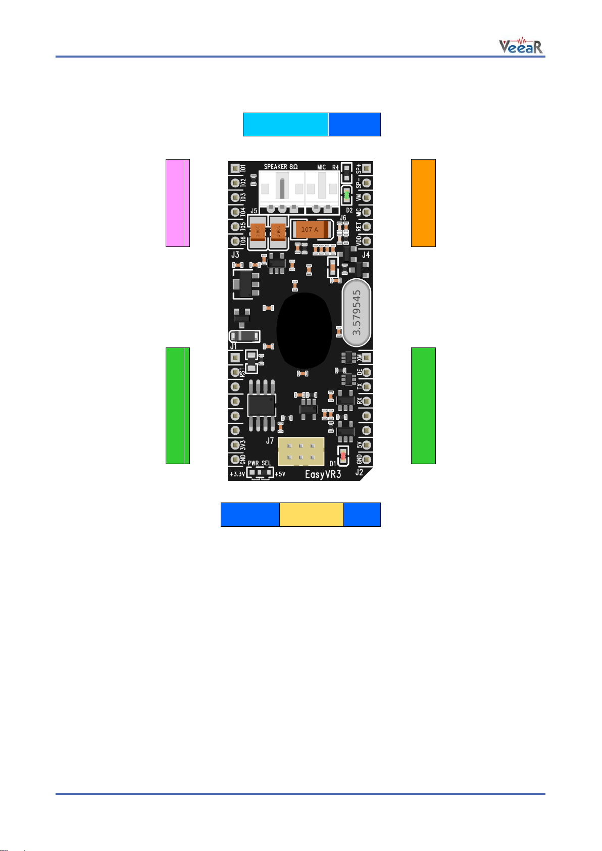
Technical specifications
The outer headers J1 and J2 are the mikroBUS™ interface connectors, providing selectable 3.3V/5V power
input to the module and voltage translated digital I/O lines, including: UART receive/transmit lines and control
pins.
The header J3 provides configurable I/O expansion lines (inputs with weak internal pull-up by default),
powered at the internal logic voltage VDD.
The header J4 contains the main analog signals, such as microphone signals and amplified DAC outputs,
which are also available on the internal right angle connectors J5 and J6.
The module can also be operated through the programming connector J7 alone, by using the QuickUSB
adapter/cable.
6 EasyVR 3 User Manual (1.0.11)
Page 7

Group
Name
Number
Pin
Type
Description
●
MIKROBUS
J1
1
-
-
(Not connected)
2
RST
I
Active low asynchronous reset (internal pull-up)
3-6
-
-
(Not connected)
7
3V3
I
3.3V DC power input
8
GND
-
Ground
J2
1
XM
I
Boot select (internal pull-down)
2
DE
O
(Reserved)
3
TX
O
Serial Data Transmit
4
RX
I
Serial Data Receive
5-6
-
-
(Not connected)
7
5V
I
5.0V DC power input
8
GND
-
Ground
●
GPIO
J3
1
IO1
I/O
General purpose I/O (VDD logic levels)
2
IO2
I/O
General purpose I/O (VDD logic levels)
3
IO3
I/O
General purpose I/O (VDD logic levels)
4
IO4
I/O
General purpose I/O (VDD logic levels)
5
IO5
I/O
General purpose I/O (VDD logic levels)
6
IO6
I/O
General purpose I/O (VDD logic levels)
●
AUDIO
J4
1
SP+
O
Differential audio output (can directly drive 8Ω
speaker)
2
SP-
O
3
VM
O
Microphone power (to support custom
microphones)
4
MIC
I
Microphone audio input
5
RET
-
Microphone return (analog ground)
6
VDD
O
Internal logic voltage (for reference only)
●
CABLES
J5
1
SP-
O
Differential audio output (can directly drive 8Ω
speaker)
3
SP+
O 2 -
-
(Not connected)
J6
1
MIC
I
Microphone audio input
2
RET
-
Microphone return (analog ground)
●
ADAPTER
J7
1
RX_P
O
Programming cable serial data receive
2
RTS_P
I
Programming cable request to send (reset/boot
control)
3
GND
-
Programming cable ground
4
5V_P
I
Programming cable 5V DC power output
5
TX_P
I
Programming cable serial data transmit
6
CTS_P
O
Programming cable clear to send (tied to ground)
Pin assignment
www.veear.eu
User Manual (1.0.11) EasyVR 3 7
Page 8
www.veear.eu
Group
Name
Type
Description
●
MISC
PWR SEL
3-Way Jumper
(SMD 0603)
Select power input and voltage level between +3.3V
and +5V with a zero Ohm resistor or solder bridge
D1
LED
Red light indicator, normally ON when the board is
powered, briefly blinking on serial data received
D2
LED
Green light indicator, turns ON when the module is
listening to its audio input
R4
Resistor
(SMD 0603)
Microphone gain resistor, default is 1.2kΩ
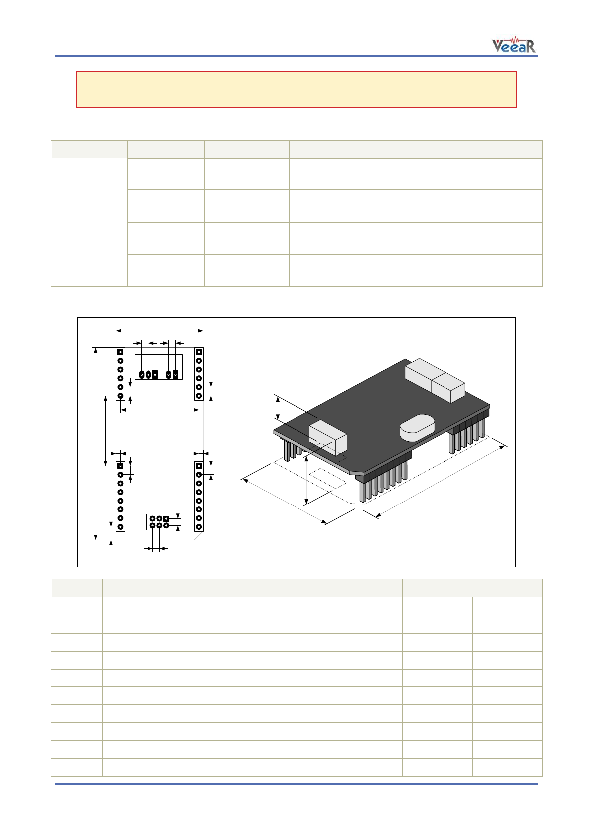
Symbol
Parameter
Units (mm / Inches)
W
Width
25.4
1.000
L
Length
56.4
2.220
H1
Height (without outer strips J1-J4)
9.5
0.375
H2
Height (with outer strips J1-J4)
17.0
0.670
E1
Connector pitch and pin spacing (of outer strips J1-J4)
2.54
0.100
E2
Connector pitch (of inner connectors J5-J7)
2.00
0.079
A
Headers horizontal spacing
22.86
0.900
B
Headers vertical spacing
20.32
0.800
C
Header vertical offset
3.81
0.150
D
Header horizontal offset
1.27
0.050
L
W
E
2
E
2
E
1
E
2
E
2
E
1
E
1
E
1
A
C
B
DD
H
1
H
2
W
L
Note: The General Purpose I/O lines (J3.1-6) are at nominal 3.0VDC level. Do not connect
higher voltages directly to these pins!
Settings and indicators
Physical dimensions
8 EasyVR 3 User Manual (1.0.11)
Page 9
Symbol
Parameter
Min
Typ
Max
Unit
5V
DC Power Input (Host) = V
SEL
3.15
5.0
5.5 V 3V3
3.15
3.3
5.5 V 5V_P
DC Power Input (Programming cable)
4.0
5.0
5.5 V Ta
Ambient Operating Temperature Range
0
25
70
°C
Symbol
Parameter
Min
Typ
Max
Unit
I
SLEEP
Sleep current (V
SEL
= 5.0V)
6
mA
I
OPER
Operating current (V
SEL
= 5.0V)
25
35
mA
I
AUDIO
Audio playback current (with 8Ω speaker)
175
250
mA
(RMS)
I
TOT
Total current consumption (excluding I/O)
25
285
mA
(RMS)
I
PEAK
Peak supply current (excluding I/O)
400 mA
Symbol
Parameter
Min
Typ
Max
Unit
VIH
Input High Voltage
2.1 5.5 V VIL
Input Low Voltage
0.0 0.9 V IIL
Input Leakage Current (0 < VI < 5.5V)
-65 µA
Symbol
Parameter
Min
Typ
Max
Unit
VOH
Output High Voltage (IOH = -0.3 mA, V
SEL
= 3.3V)
2.6 3.3
V
Output High Voltage (IOH = -0.3 mA, V
SEL
= 5.0V)
4.3 5.0 V VOL
Output Low Voltage (IOL = 5 mA)
0.0 0.2
V
Symbol
Parameter
Min
Typ
Max
Unit
VIH
Input High Voltage
1.4
(0.8)
5.5
V
VIL
Input Low Voltage
0.0
(0.7)
0.5
V
IIN
Input Current (0 < VI < 3.3V)
0
0.2
0.4
mA
Input Current (0 < VI < 5.5V)
0
0.5
0.7
mA
Symbol
Parameter
Min
Typ
Max
Unit
VIH
Input High Voltage
2.1 5.5
V
VIL
Input Low Voltage
0.0 0.6 V IIL
Input Leakage Current (0 < VI < 5.5V)
-85 µA
Recommended Operating Conditions
Power Supply Requirements
www.veear.eu
Electrical Characteristics
These are applicable to pins RX, TX_P.
These are applicable to pins TX, DE.
These are applicable to pin XM.
These are applicable to pin RST.
User Manual (1.0.11) EasyVR 3 9
Page 10
www.veear.eu
Symbol
Parameter
Min
Typ
Max
Unit
VOH
Output High Voltage (IOH = -5 mA)
2.4 3.0 V VOL
Output Low Voltage (IOL = 8 mA)
0.0 0.6
V
Symbol
Parameter
Min
Typ
Max
Unit
VIH
Input High Voltage
2.4
3.0
3.3 V VIL
Input Low Voltage
-0.1
0.0
0.75 V IIL
Input Leakage Current (0 < VI < 3V, Hi-Z Input)
<1
10
µA
RPU
Pull-up Resistance
Strong
10 kΩ
Weak
200 kΩ
VOH
Output High Voltage (IOH = -5 mA)
2.4 3.0 V VOL
Output Low Voltage (IOL = 8 mA)
0.0 0.6
V
VCC
Idle
Start 1 0 0 0 0 0 1 0
Stop
Idle
0V
These are applicable to pin RX_P.
These are applicable to pins IO1 – IO6.
Serial Interface
The EasyVR 3 communicates via an asynchronous serial interface (commonly known as UART interface),
with the following features:
Baud Rate: 9600 (default), 19200, 38700, 57600, 115200
Frame: 8 Data bits, No parity, 1 Stop bit
The receiver input data line is RX, while the transmitter output data line is TX. No handshake lines are used.
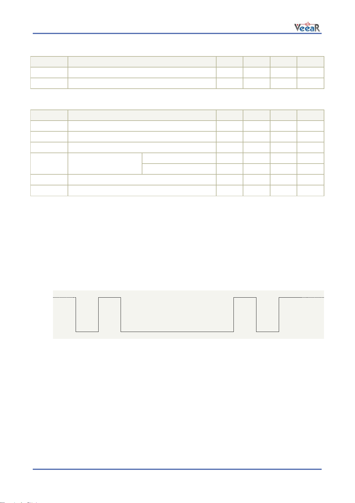
Example of a serial data frame representing character “A” (decimal 65 or hexadecimal 41):
See also chapter Communication Protocol later on this manual for communication details.
10 EasyVR 3 User Manual (1.0.11)
Page 11
www.veear.eu
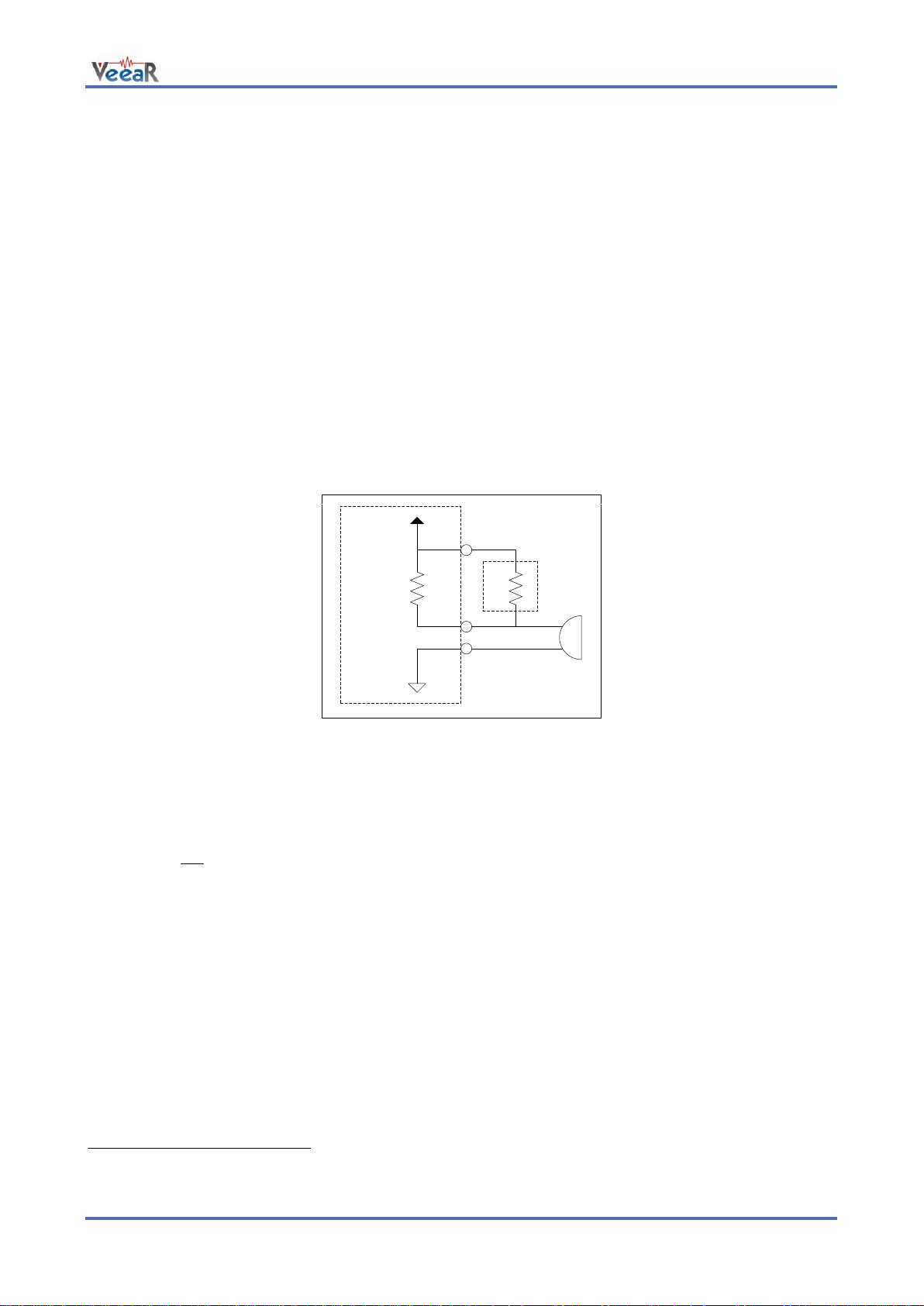
MIC
VM
RET
3V
AGND
R4
1.2kΩ
Module
Internals
External
Microphone
+
-
Rx
Optional
Microphone circuit
3
Microphone
The microphone provided with the EasyVR 3 module is an omnidirectional electret condenser microphone
(Horn EM9745P-382):
Sensitivity -38dB (0dB=1V/Pa @1KHz)
Load Impedance 2.2K
Operating Voltage 3V
Almost flat frequency response in the range 100Hz – 20kHz
The microphone circuit is optimized for use at ARMS_LENGTH (default, about 60cm) or FAR_MIC distance
settings.
If you use a microphone with different specifications the recognition accuracy may be adversely affected.
Differences in rated load impedance and sensitivity can be compensated to a certain extent by changing the
microphone gain. This can be done in several ways:
Replacing the internal gain resistor R4 (1.2kΩ)
Adding an external resistor Rx going in parallel with R4 (it can only reduce gain, useful for HEADSET
distance settings)
Removing the internal resistor R4 and using only the external resistor Rx
Modifying gain resistance
You can calculate the overall microphone gain resistance using the formula below:
Rs is the optimal microphone gain resistance
I is the impedance rating of the microphone
G is the desired overall system gain, defined as follows:
S is the sensitivity rating of the microphone you want to use, and it is specified in –dB in the microphone’s
specification3.
Converting uBars to Pascal: microphone manufacturers specify the sensitivity referencing to uBars or
Pascal. If the microphone sensitivity is referenced to uBars, simply add 20 dB to the rating. For example, -58
dB/uBars + 20dB = -38 dBV/Pa.
User Manual (1.0.11) EasyVR 3 11
1. If the module is configured for HEADSET microphone distance (typically a few centimeters from the
user’s mouth), then the overall system gain should be -49 dB (0dB=1v/Pa@1KHz);
2. If the module is configured for ARMS_LENGTH microphone distance (typically 60-90 cm from the
user's mouth – this is the default setting of EasyVR), then the overall system gain should be -44 dB;
3. If the module is configured for FAR_MIC microphone distance (up to about 3 meters from the user's
mouth), then the overall system gain should be -43 dB.
Page 12
www.veear.eu
cavity
clear area
internal
diaphragm
Examples
1) The optimal gain resistance for the bundled microphone at ARMS_LENGTH distance is:
Use the closest standard 5% resistor to Rs. In this example, it would be 1.1 kΩ. The EasyVR uses a 1.2 kΩ
resistor to allow use of “FAR” settings without replacing the internal resistor.
Sometimes you might also need to compensate some gain loss for a voltage lower than the microphone
ratings (using a larger resistor value sets a higher input gain).
2) The gain resistance for the bundled microphone at HEADSET distance would be:
In this case you may just add an external 1.2 kΩ resistor to get a gain resistance of 600 Ω (close enough).
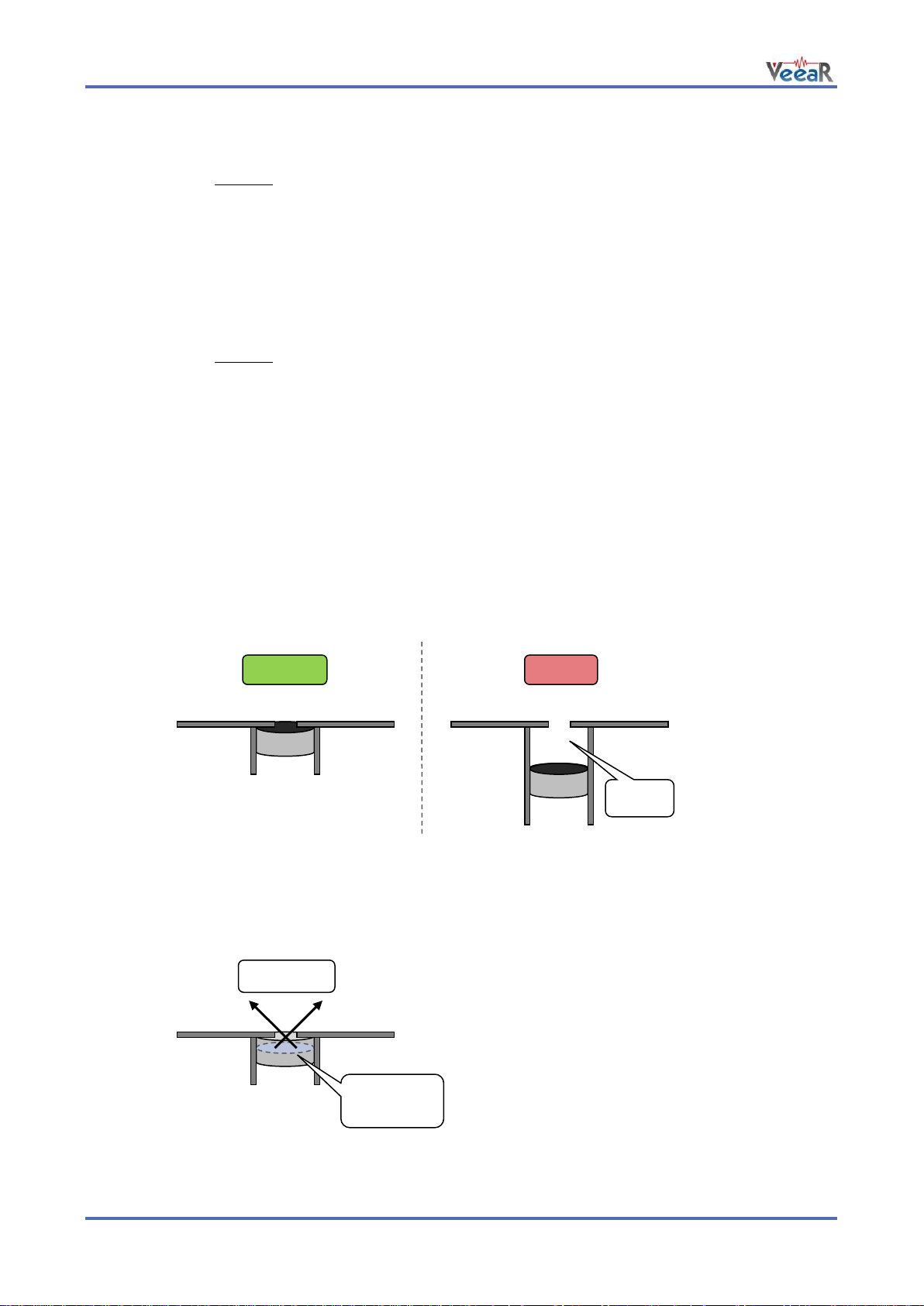
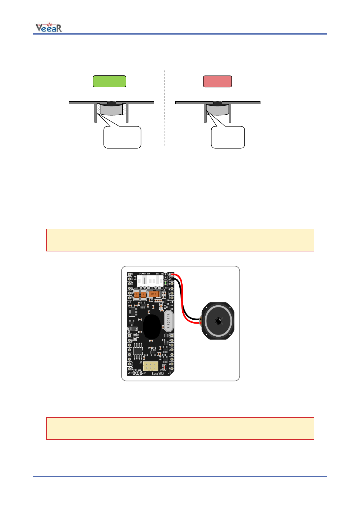
Positioning guidelines
Please note that improper acoustic positioning of the microphone will reduce recognition accuracy. Many
mechanical arrangements are possible for the microphone element, and some will work better than others.
When mounting the microphone in the final device, keep in mind the following guidelines:
1. Flush Mounting - The microphone element should be positioned as close to the mounting surface
as possible and should be fully seated in the plastic housing. There must be no airspace between
the microphone element and the housing. Having such airspace can lead to acoustic resonance,
which can reduce recognition accuracy.
2. No Obstructions, Large Hole - The area in front of the microphone element must be kept clear of
obstructions to avoid interference with recognition. The diameter of the hole in the housing in front of
the microphone should be at least 5 mm. Any necessary plastic surface in front of the microphone
should be as thin as possible, being no more than 0.7 mm, if possible.
3. Insulation - The microphone should be acoustically isolated from the housing if possible. This can
be accomplished by surrounding the microphone element with a spongy material such as rubber or
foam. The provided microphone has this kind of insulating foam. The purpose is to prevent auditory
12 EasyVR 3 User Manual (1.0.11)
Page 13
www.veear.eu
absorbent
material
fastened
directly
noises produced by handling or jarring the device from being “picked up” by the microphone. Such
extraneous noises can reduce recognition accuracy.
4. Distance - If the microphone is moved from 15 cm to 30 cm from the speaker’s mouth, the signal
power decreases by a factor of four. The difference between a loud and a soft voice can also be
more than a factor of four. Although the internal preamplifier of the EasyVR compensates for a wide
dynamic range of input signal strength, if its range is exceeded, the user application can provide
feedback to the speaker about the voice volume (see appendix Error codes).
Audio Output
The EasyVR 3 audio output interface is capable of directly driving an 8Ω speaker. It can also be connected
to an external audio amplifier to drive lower impedance loudspeakers.
Note: Connecting speakers with lower impedance directly to the module may permanently
damage the EasyVR audio output or the whole module.
It is possible to connect higher impedance loads such as headphones, provided that you scale down the
output power according to the speaker ratings, for example using a series resistor. The exact resistor value
depends on the headphone sensitivity and the desired output volume (usually in the order of 1-10kΩ).
Note: Connecting headphone speakers directly to the EasyVR audio output may damage your
hearing.
User Manual (1.0.11) EasyVR 3 13
Page 14
www.veear.eu
IOn
LED
IOn
Inverted
OUT
5V
IOn
-
12V
RELAY
Z
Switched
Load
AC MAINS
Voltage
I/O pin directly driving a
low-current LED
I/O pin connected to high
impedance 5V circuit (such as
MCU input pin)
I/O pin switching a load on a high voltage
line using a 12V relay
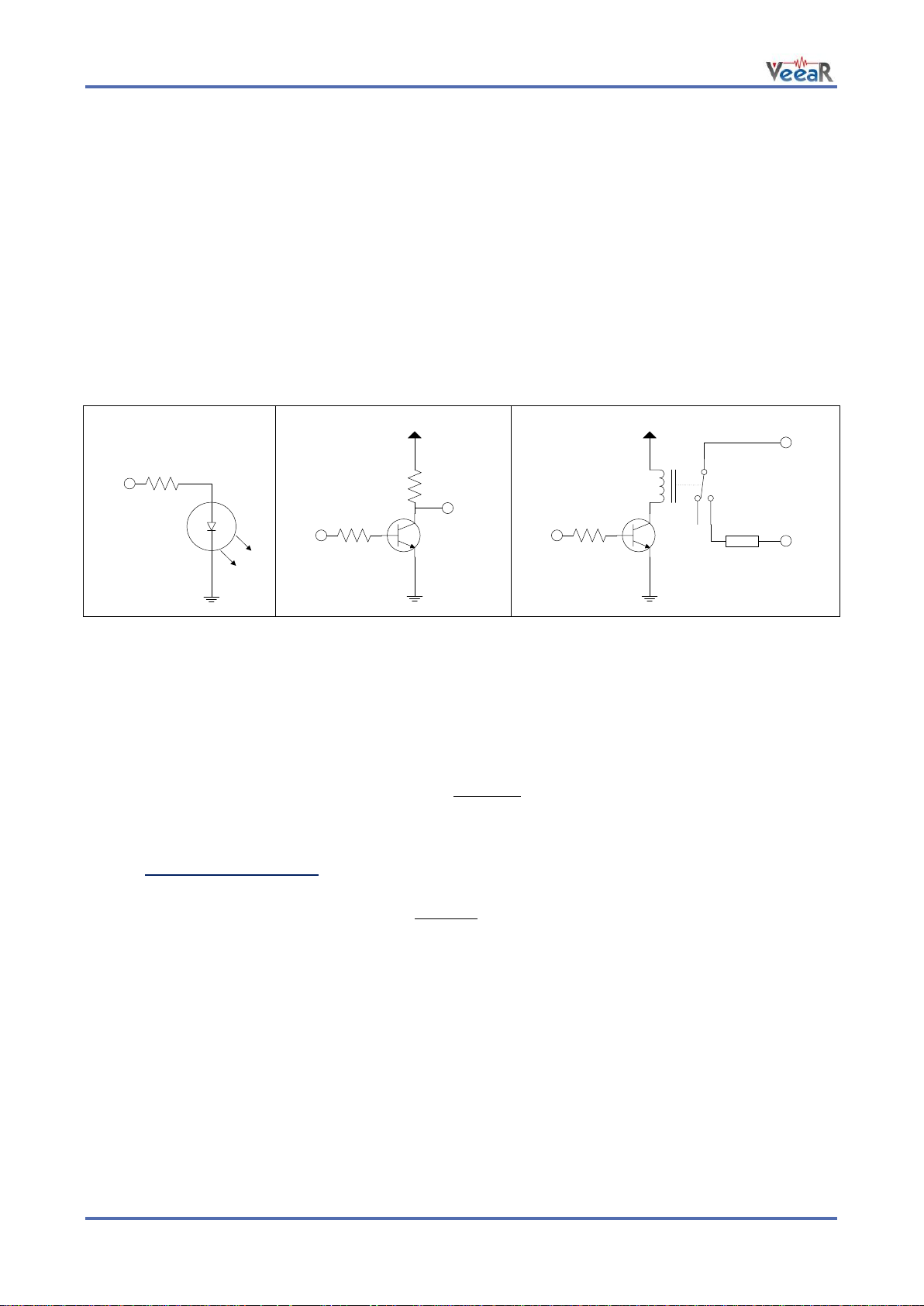
General Purpose I/O
Since the EasyVR communication interface takes two pins of the host controller, a few spare I/O pins are
provided, which can be controlled with the communication protocol, to get those pins back for basic tasks,
such as lighting an LED or reading a switch.
The six I/O pins IO1–IO6 are connected directly to the embedded microcontroller on the EasyVR module, so
they are referenced to the internal 3.0V regulated power supply VDD. If you need to interface to circuits
using a different supply, there are a number of solutions you can adopt. Some of these are outlined below
(here IOn indicates any one of the six I/O pins of the EasyVR).
Use a pin as an output
All the I/O pins are inputs with weak internal pull-up after power on. You must explicitly configure a pin before
you can use it as an output (see the example code Use general purpose I/O pins).
The exact components values in these circuits may vary. You need to calculate required values for your
application and choice of components. For example, resistor value for the LED circuit can be calculated
approximately as:
Where V
is the LED forward voltage, as reported on the LED datasheet, at the driving current IOH (see
LED
section Electrical Characteristics). Let’s assume a typical low-current LED has a VF=1.8V at 5mA, the
resistor value is:
Now stay on the safe side and choose a slightly larger resistor, such as 150Ω.
If you want to drive higher current LEDs, you need a circuit like the second one, where you put the LED
between the output resistor and the collector of the NPN transistor.
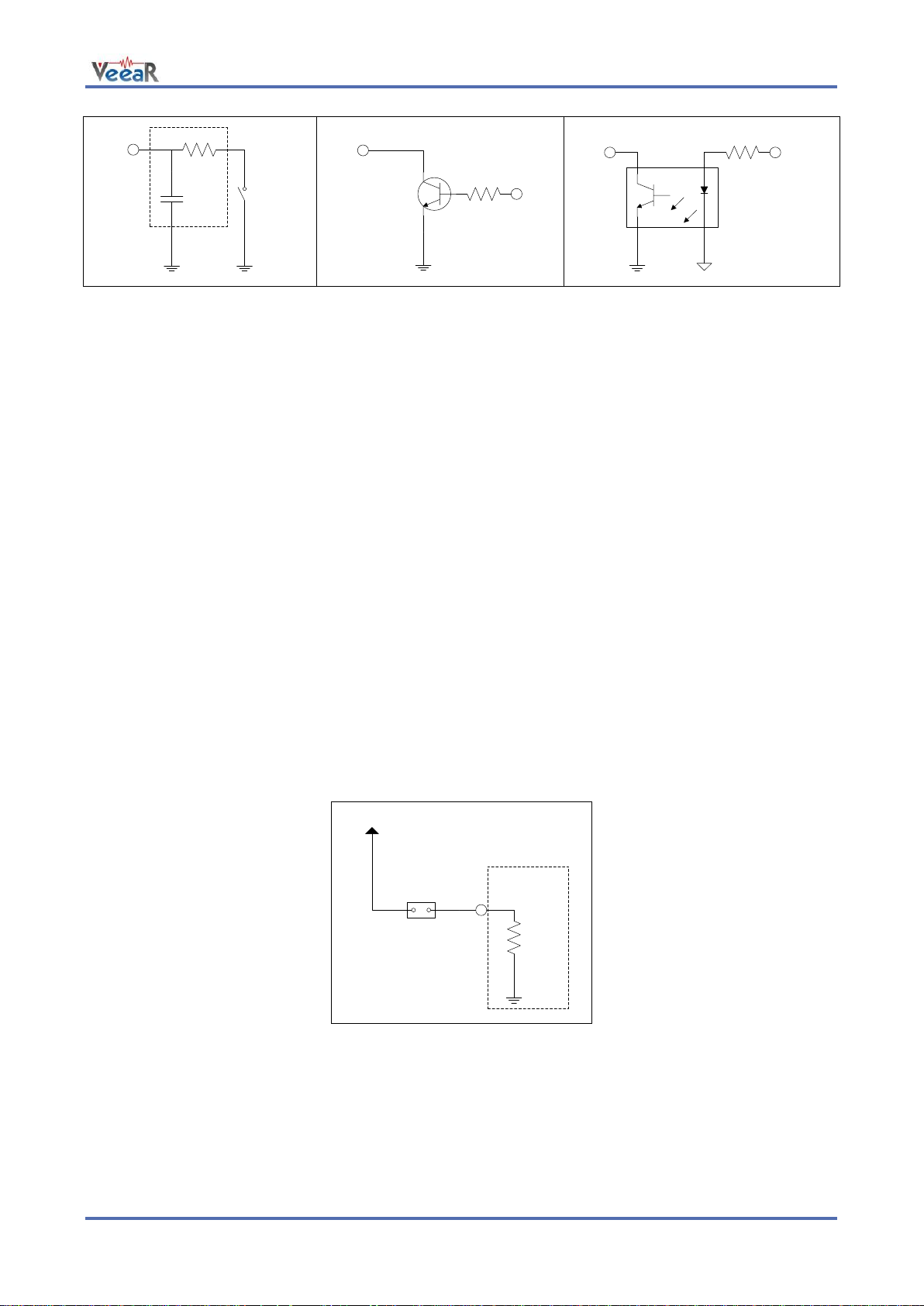
Use a pin as an input
All the I/O pins are inputs with weak internal pull-up after power on or reset. You may also configure the pin
to have a strong pull-up or no pull-up at all (see the example code Use general purpose I/O pins).
14 EasyVR 3 User Manual (1.0.11)
Page 15
www.veear.eu
IOn
SWITCH
optional
filter
IOn
5V
IN
IOn
Isolated
IN
optocoupler
I/O pin connected to a switch
(or switching sensor)
I/O pin connected 5V source
(such as MCU output pin)
I/O pin with isolated input (for safety
circuits)
/XM
VCC
Jumper
Internal
Pull-down
Boot mode selection circuit
All these circuits assume the EasyVR pin has been configured with an internal pull-up (passive components
value can be adjusted to account for weak or strong pull-up).
Disabling the internal pull-up could be used to put the pin in high-impedance state, for example to simulate a
tri-state or open-drain output port.
Again, you should refer to the manufacturer’s datasheet when interfacing any external components and to
calculate required resistors values or other passive components.
Flash Update
The EasyVR module includes a boot loader that allows to update the firmware and to download new sound
tables or custom grammars to the on-board memory.
The boot mode is activated by keeping the XM signal to a high logical level at power on or reset. This can be
easily done with a jumper (or switch) taking the signal to a suitable pull-up resistor.
To download a firmware update, a sound table or a custom grammar to the EasyVR, power on the module
with the jumper closed. For normal operation, just leave the jumper open. Do not change the jumper position
while the module is already powered on. It is safe to change XM level while the module is reset (RST low).
To learn how to download new sound tables or custom grammars to your EasyVR 3 module, have a look at
the section Using Custom Data.
User Manual (1.0.11) EasyVR 3 15
Page 16
www.veear.eu
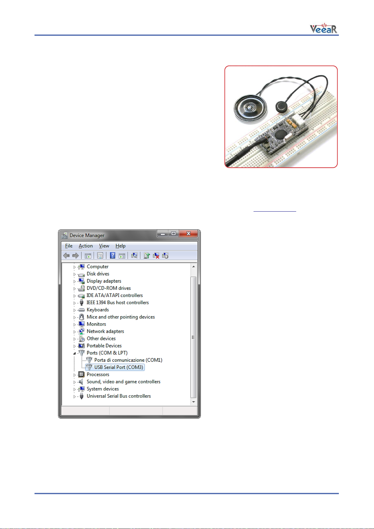
Quick start for using the module
EasyVR 3 as a Development Board
The QuickUSB serial adapter cable can be used to program voice
commands and sound outputs into an EasyVR 3 module and
quickly test it from your PC.
Just connect the microphone and an 8Ω speaker to the module,
plug-in the adapter cable and you are ready to go.
The EasyVR 3 boot mode is managed automatically through the
serial handshake lines, so you don’t need to set any jumper.
How to get started
1. Connect the microphone to the 2-way socket MIC (J6)
2. Connect an 8Ω speaker to the 3-way socket SPEAKER (J5)
3. Connect a QuickUSB cable to the 3x2 pins socket (J7)
4. Plug the USB end of the adapter cable to your PC.
The first time it may take some time to install the required drivers (see Software Setup)
5. If your installation is successful you will see a new virtual COM port in your Device Manager:
(The actual COM port number may vary)
6. Now start the EasyVR Commander software
7. Choose your COM Port and click connect
8. Then enjoy your EasyVR!
16 EasyVR 3 User Manual (1.0.11)
Page 17
www.veear.eu
Pin
Name
Type
Notes
1
RX_P
I
Adapter should have TTL/LVTTL compatible inputs (VIH = 2.0V)
2
RTS_P
O
Adapter outputs can have 3.3V or 5V levels
RTS handshake is required for automatic reset and boot mode control
3
GND
-
Ground
4
5V_P
O
Adapter should provide a 5V DC power output for the module
(see Recommended Operating Conditions and Power Supply
Requirements)
5
TX_P
O
Adapter outputs can have 3.3V or 5V levels
6
CTS_P
I
CTS is tied to GND on the module
Serial Adapter Interface
Connector J7 is a 6-pin socket specifically designed for the QuickUSB serial adapter cable, but another
adapter may also be used provided that it uses the same connector type, pin assignment and electrical
specifications.
Connector type is Hirose DF11 Series (female on the adapter cable, male on the module).
User Manual (1.0.11) EasyVR 3 17
Page 18
www.veear.eu
EasyVR Shield 3 for Arduino
Product description
The EasyVR Shield 3 is an adapter board for the EasyVR 3
module, designed to simplify its use among the Arduino
community.
The Shield is compatible with any Arduino board using UNOR3 Shield headers, running at either 3.3V or 5V levels, by
using the IOREF pin to select the EasyVR operating voltage.
It is also backward compatible with earlier Arduino boards that
don’t have the IOREF pin, which are using 5V I/O levels by
default.
If your board does not have the IOREF pin but it is running at 3.3V, you can still operate the EasyVR Shield 3
correctly if you manually connect pins IOREF and 3V3 together, for example with a jumper wire.
The board comes with separate Arduino stackable headers for the Shield interface. The EasyVR 3 module is
also provided separately.
Note: The EasyVR 3 module and all stackable headers must be soldered before use!
EasyVR Shield 3 Features
Compatible with Arduino boards that have the 1.0 Shield interface (UNO R3) and legacy boards
including, but not limited to:
o Arduino Duemilanove
o Arduino Uno
o Arduino Mega
o Arduino Leonardo
o Arduino Due
Supports 5V and 3.3V main boards through the IOREF pin
Supports direct connection to the PC on main boards with a separate USB/Serial chip and a special
software-driven “bridge” mode on boards with only native USB interface, for easy access by the
EasyVR Commander
Enables different modes of serial connection and also flash updates to the embedded EasyVR
module (through the Mode Jumper)
Supports remapping of serial pins used by the Shield (in SW mode)
Provides a 3.5mm audio output jack suitable for headphones or as a line out
EasyVR Shield 3 fully assembled
18 EasyVR 3 User Manual (1.0.11)
Page 19
PROG
MODE JUMPER
LED
SW
HW
PC
UP
LEO
EASYVR
GPIO
IO1
IO2
IO3
IO4
IO5
IO6
ARDUINO
POWER
IOREF
RESET
3V3
5V
GND
GND
VIN
ARDUINO
ANALOG
A0
A1
A2
A3
A4
A5
SDA
ARDUINO
DIGITAL
SCL
AREF
GND
13
12
11
10
9
8
7
ARDUINO
DIGITAL
6 5 4 3 2 1 0
3.5mm JACK
MIC
SPEAKER
LINE OUT
EASYVR AUDIO
SW SERIAL
PINS
SW SERIAL
PINS
TX – D13
D9 – TX
RX – D12
D8 – RX
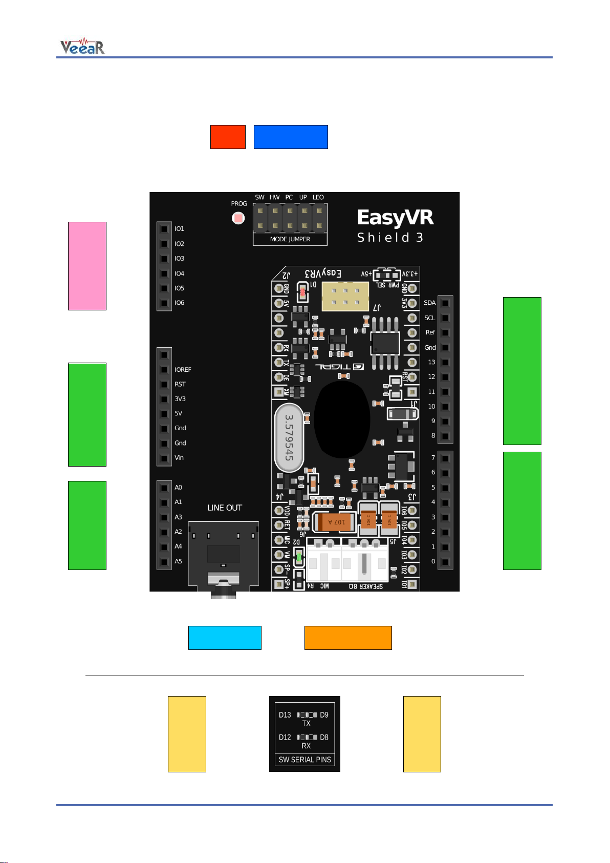
Technical specifications
Board overview
www.veear.eu
User Manual (1.0.11) EasyVR 3 19
(Top View)
(Detail – Bottom View)
Page 20

www.veear.eu
Group
Pin
Description
●
ARDUINO
HEADERS
-
Arduino UNO-R3 Shield interface, pass-through connectors
(Pins 0-1 are in use when J12 is set to UP, PC, HW or LEO)
(Pins 12-13 or 8-9 are in use when J12 is set to SW)
●
EASYVR
AUDIO
-
Audio cables connectors of the EasyVR 3 module (microphone and
speaker)
●
LINE OUT
-
3.5mm stereo/mono jack (16Ω - 32Ω headphones or line-level output)
●
MODE
JUMPER
SW
Arduino Software Serial (connected to pins 12-13 or 8-9)
HW
Arduino Hardware Serial (connected to pins 0-1)
PC
PC Mode (Arduino disabled, EasyVR in command mode)
UP
Update Mode (Arduino disabled, EasyVR in boot mode)
LEO
Leonardo Update (Arduino enabled, EasyVR in boot mode)
●
PROG
-
Red light indicator for Flash programming modes (UP and LEO)
●
SW SERIAL
PINS
RX
Use resistor to select Software Serial RX pin: 12 or 8
TX
Use resistor to select Software Serial TX pin: 13 or 9
●
EASYVR
GPIO
IO1
General purpose I/O as found on the embedded EasyVR 3 module
(referenced at the internal VDD logic level – see note below)
IO2
IO3
IO4
IO5
IO6
Pin assignment
Note: The General Purpose I/O lines (IO1-IO6) are at nominal 3.0VDC level. Do not connect
higher voltages directly to these pins!
Mode Jumper settings
This jumper selects the operating mode of the EasyVR Shield and it can be placed in one of four positions:
o SW – Software Serial mode
Use it for controlling the EasyVR module from your Arduino sketch through a software serial port
(using pins 12-13). You can also connect the EasyVR Commander in this mode, provided that the
running sketch implements bridge mode (see the Arduino library examples).
o HW – Hardware Serial mode
Use it for controlling the EasyVR module from your Arduino sketch through the hardware serial port
(using pins 0-1).
o PC – PC Connection mode
Use it for direct connection with the EasyVR Commander. In this mode, the Arduino controller is held
in reset and only the embedded USB/Serial adapter is used.
o UP – Flash Update mode
Use it for firmware updates or to download sound table data and custom grammars to the on-board
flash memory from the EasyVR Commander. In this mode, the Arduino controller is held in reset and
only the embedded USB/Serial adapter is used. The EasyVR module is set in boot mode.
o LEO – Leonardo Update mode
This is similar to the regular Flash Update mode, for Arduino boards that don’t have a separate
USB/Serial adapter, such as Arduino Leonardo. The EasyVR module is set in boot mode, but the
Arduino controller is not reset and it must be running the special “bridge” sketch.
20 EasyVR 3 User Manual (1.0.11)
Page 21

www.veear.eu
Software Serial Pins settings
On the bottom side of the board there are two SMD resistors that you can move to select the two pins of
Arduino that the EasyVR will be connected to when in Software Serial mode (Mode Jumper on SW).
o RX – Software Serial Receiver pin
D12 – Use digital pin 12 as serial receiver (default)
D8 – Use digital pin 8 as serial receiver
o TX – Software Serial Transmitter pin
D13 – Use digital pin 13 as serial transmitter (default)
D9 – Use digital pin 9 as serial transmitter
The choice of pins 12-13 is maintained for backward compatibility with the previous hardware revisions of the
EasyVR Shield. However those pins may also be used for the SPI interface, so another choice of pins 8-9 is
provided. If you want to use different pins make sure the receiver pin supports change interrupts.
User Manual (1.0.11) EasyVR 3 21
Page 22

www.veear.eu
4
Quick start guide for using the Shield
Follow these few steps to start using your EasyVR Shield 3 and Arduino:
1. Insert the EasyVR Shield on top of your Arduino board
2. If you want audio output, either wire an 8Ω speaker into the SPEAKER connector (J5) on the
EasyVR module or connect headphones or amplified speakers to the LINE OUT 3.5mm audio jack
on the Shield
3. Connect the supplied microphone to the MIC connector (J6) on the EasyVR module
4. Install the EasyVR Arduino libraries4 on your PC (details at http://arduino.cc/en/Guide/Libraries)
5. Connect your Arduino board to your PC via USB.
With Arduino Leonardo – Due (Native USB)
Test the Shield with Arduino
1. Make sure the Mode jumper (J7) is in the HW position
2. Open the example sketch TestEasyVR from your IDE menu “File” > “Examples” > “EasyVR”
3. Upload the sketch and open the “Serial Monitor” window
4. Send a question mark “?” (without quotes)
5. After a few seconds you should receive an “EasyVR detected” message
Test the Shield with the EasyVR Commander
1. Make sure the Mode jumper (J7) is in the HW position
2. Open and upload the example sketch TestEasyVR or EasyVRBridge (see menu “File” > “Examples”
> “EasyVR”)
3. Close the serial monitor window in the Arduino IDE
4. Open the EasyVR Commander and connect to the same serial port used by Arduino
Download a new sound-table or firmware update
1. Make sure the Mode jumper (J7) is in the LEO position
2. Open and upload the example sketch TestEasyVR or EasyVRBridge (see menu “File” > “Examples”
> “EasyVR”)
3. Open the EasyVR Commander and select the Arduino serial port
4. While disconnected choose “Update Custom Data” from the “File” menu
The Arduino library archive file can be found in the EasyVR Commander program folder.
22 EasyVR 3 User Manual (1.0.11)
Page 23

www.veear.eu
With Arduino 2009 – Uno – Mega
Test the Shield with Arduino
1. Set the Mode jumper (J7) in the SW position
2. Open the example sketch TestEasyVR from your IDE menu “File” > “Examples” > “EasyVR”
3. Upload the sketch and open the “Serial Monitor” window
4. See comments on top of the sketch for usage details
Test the Shield with the EasyVR Commander
1. Make sure the Mode jumper (J7) is in the PC position
2. Open the EasyVR Commander and connect to the same serial port used by Arduino
Download a new sound-table or firmware update
1. Make sure the Mode jumper (J7) is in the UP position
2. Open the EasyVR Commander and select the Arduino serial port
3. While disconnected choose “Update Custom Data” from the “File” menu (or “Update Firmware” from
the “Help” menu)
When the EasyVR Commander is connected, you can also generate a template code for Arduino, that will
use the provided libraries (see EasyVR Arduino Library Documentation). All you need is to write actions for
each recognized command.
User Manual (1.0.11) EasyVR 3 23
Page 24

www.veear.eu
VCC
GND
ERX
ETX
EasyVR
3.3V – 5V
RX
Host MCU
EasyVR Programming
Communication Protocol
Introduction
Communication with the EasyVR module uses a standard UART interface compatible with 3.3-5V
TTL/CMOS logical levels, according to the powering voltage VCC.
A typical connection to an MCU-based host:
GND
TX
The initial configuration at power on is 9600 baud, 8 bit data, No parity, 1 bit stop. The baud rate can be
changed later to operate in the range 9600 - 115200 baud.
The communication protocol only uses printable ASCII characters, which can be divided in two main groups:
Command and status characters, respectively on the TX and RX lines, chosen among lower-case
letters.
Command arguments or status details, again on the TX and RX lines, spanning the range of capital
letters.
Each command sent on the TX line, with zero or more additional argument bytes, receives an answer on the
RX line in the form of a status byte followed by zero or more arguments.
There is a minimum delay before each byte sent out from the EasyVR module to the RX line, that is initially
set to 20 ms and can be selected later in the ranges 0 - 9 ms, 10 - 90 ms, and 100 ms - 1 s. That accounts
for slower or faster host systems and therefore suitable also for software-based serial communication (bitbanging).
Since the EasyVR serial interface also is software-based, a very short delay might be needed before
transmitting a character to the module, especially if the host is very fast, to allow the EasyVR to get back
listening to a new character.
The communication is host-driven and each byte of the reply to a command has to be acknowledged by the
host to receive additional status data, using the space character. The reply is aborted if any other character
is received and so there is no need to read all the bytes of a reply if not required.
Invalid combinations of commands or arguments are signaled by a specific status byte, that the host should
be prepared to receive if the communication fails. Also a reasonable timeout should be used to recover from
unexpected failures.
If the host does not send all the required arguments of a command, the command is ignored by the module,
without further notification, and the host can start sending another command.
The module automatically goes to lowest power sleep mode after power on. To initiate communication, send
any character to wake-up the module.
24 EasyVR 3 User Manual (1.0.11)
Page 25

www.veear.eu
'@' (40h)
Minimum argument value (-1)
'`' (60h)
Maximum argument value (+31)
'A' (41h)
Zero argument value (0)
' ' (20h)
Read more status arguments
ASCII
'@'
'A'
'B'
'C'
...
'Y'
'Z'
'^'
'['
'\'
']'
'_'
'`'
HEX
40
41
42
43
...
59
5A
5B
5C
5D
5E
5F
60
Value
-1 0 1 2 ...
24
25
26
27
28
29
30
31
Arguments Mapping
Command or status messages sent over the serial link may have one or more numerical arguments in the
range -1 to 31, which are encoded using mostly characters in the range of uppercase letters. These are
some useful constants to handle arguments easily:
ARG_MIN
ARG_MAX
ARG_ZERO
ARG_ACK
Having those constants defined in your code can simplify the validity checks and the encoding/decoding
process. For example (in pseudo-code):
# encode value 5
FIVE = 5 + ARG_ZERO
# decode value 5
FIVE – ARG_ZERO = 5
# validity check
IF ARG < ARG_MIN OR ARG > ARG_MAX THEN ERROR
Just to make things clearer, here is a table showing how the argument mapping works:
User Manual (1.0.11) EasyVR 3 25
Page 26

www.veear.eu
'b' (62h)
Abort recognition, training or playback in progress if any or do nothing
Known issues:
In firmware ID 0, any other character received during recognition will prevent this command from
stopping recognition that will continue until timeout or other recognition results.
Expected replies: STS_SUCCESS, STS_INTERR
's' (73h)
Go to the specified power-down mode
[1]
Sleep mode (0-8):
0 = wake on received character only
1 = wake on whistle or received character
2 = wake on loud sound or received character
3-5 = wake on double clap (with varying sensitivity) or received character
6-8 = wake on triple clap (with varying sensitivity) or received character
Expected replies: STS_SUCCESS, STS_AWAKEN
'v' (76h)
Set SD level
[1]
Strictness control setting (1-5):
1 = easy
2 = default
5 = hard
A higher setting will result in more recognition errors.
Expected replies: STS_SUCCESS
'k' (6Bh)
Set SI knob to specified level
[1]
Confidence threshold level (0-4):
0 = loosest:more valid results
2 = typical value (default)
4 = tightest:fewer valid results
Note: knob is ignored for trigger words
Expected replies: STS_SUCCESS
'k' (6Bh)
Set the microphone operating distance
[1]
Fixed to (-1)
[2]
Distance settings (1-3):
1 = “headset” (around 5cm from speaker’s mouth)
2 = “arms length” (default setting, from about 50cm to 1m)
3 = “far mic” (up to around 3m)
Expected replies: STS_SUCCESS
Command Details
This section describes the format of all the command strings accepted by the module. Please note that
numeric arguments of command requests are mapped to upper-case letters (see above section).
CMD_BREAK
CMD_SLEEP
CMD_LEVEL
CMD_KNOB
CMD_MIC_DIST
26 EasyVR 3 User Manual (1.0.11)
Page 27

'l' (6Ch)
Set SI language
[1]
Language:
0 = English
1 = Italian
2 = Japanese
3 = German
4 = Spanish
5 = French
Expected replies: STS_SUCCESS
'o' (6Fh)
Set recognition timeout
[1]
Timeout (-1 = default, 0 = infinite, 1-31 = seconds)
Expected replies: STS_SUCCESS
'i' (69h)
Activate SI recognition from specified word set
[1]
Word set index (0-3)
Expected replies: STS_SIMILAR, STS_TIMEOUT, STS_ERROR
't' (74h)
Train specified SD/SV command
[1]
Group index (0 = trigger, 1-15 = generic, 16 = password)
[2]
Command position (0-31)
Expected replies: STS_SUCCESS, STS_RESULT, STS_SIMILAR, STS_TIMEOUT, STS_ERROR
'g' (67h)
Insert new SD/SV command
[1]
Group index (0 = trigger, 1-15 = generic, 16 = password)
[2]
Position (0-31)
Expected replies: STS_SUCCESS, STS_OUT_OF_MEM
'u' (75h)
Remove SD/SV command
[1]
Group index (0 = trigger, 1-15 = generic, 16 = password)
[2]
Position (0-31)
Expected replies: STS_SUCCESS
'd' (64h)
Activate SD/SV recognition
[1]
Group index (0 = trigger, 1-15 = generic, 16 = password)
Expected replies: STS_RESULT, STS_SIMILAR, STS_TIMEOUT, STS_ERROR
CMD_LANGUAGE
CMD_TIMEOUT
CMD_RECOG_SI
www.veear.eu
CMD_TRAIN_SD
CMD_GROUP_SD
CMD_UNGROUP_SD
CMD_RECOG_SD
User Manual (1.0.11) EasyVR 3 27
Page 28

www.veear.eu
'e' (65h)
Erase training of SD/SV command
[1]
Group index (0 = trigger, 1-15 = generic, 16 = password)
[2]
Command position (0-31)
Expected replies: STS_SUCCESS
'n' (6Eh)
Label SD/SV command
[1]
Group index (0 = trigger, 1-15 = generic, 16 = password)
[2]
Command position (0-31)
[3]
Length of label (0-31)
[4-n]
Text for label (ASCII characters from 'A' to '`')
Expected replies: STS_SUCCESS
'c' (63h)
Request count of SD/SV commands in the specified group
[1]
Group index (0 = trigger, 1-15 = generic, 16 = password)
Expected replies: STS_COUNT
'p' (70h)
Read SD/SV command data (label and training)
[1]
Group index (0 = trigger, 1-15 = generic, 16 = password)
[2]
Command position (0-31)
Expected replies: STS_DATA
'm' (6Dh)
Request bit-mask of non-empty groups
Expected replies: STS_MASK
'r' (72h)
Reset all commands and groups
'R' (52h)
Confirmation character
Expected replies: STS_SUCCESS
'x' (78h)
Request firmware identification
Expected replies: STS_ID
'y' (79h)
Set transmit delay
[1]
Time (0-10 = 0-10 ms, 11-19 = 20-100 ms, 20-28 = 200-1000 ms)
Expected replies: STS_SUCCESS
CMD_ERASE_SD
CMD_NAME_SD
CMD_COUNT_SD
CMD_DUMP_SD
CMD_MASK_SD
CMD_RESETALL
CMD_ID
CMD_DELAY
28 EasyVR 3 User Manual (1.0.11)
Page 29

'a' (61h)
Set communication baud-rate
[1]
Speed mode:
1 = 115200
2 = 57600
3 = 38400
6 = 19200
12 = 9600
Expected replies: STS_SUCCESS
'q' (71h)
Configure, query or modify general purpose I/O pins
[1]
Pin number (1 = pin IO1, 2 = pin IO2, 3 = pin IO3)
[2]
Pin mode (0 = output low, 1 = output high, 2 = input*, 3 = input strong**, 4 = input weak***)
* High impedance input (no pull-up)
**Strong means ~10K internal pull-up
***Weak means ~200K internal pull-up (default after power up)
Expected replies: STS_SUCCESS (mode 0-1), STS_PIN (mode 2-4)
'w' (77h)
Wave table entry playback
[1-2]
Two positive values that form a 10-bit index to the sound table (index = [1] * 32 + [2], 0 = built-in
“beep”, 1-1023 = sound index)
[3]
Playback volume (0-31, 0 = min volume, 15 = full scale, 31 = double gain)
Expected replies: STS_SUCCESS, STS_ERROR
'w' (77h)
Play a DTMF key tone or dial tone
[1]
Fixed to (-1)
[2]
Index of phone tone to play (0-9 for digits, 10 for '*' key, 11 for '#' key and 12-15 for extra keys
'A' to 'D', -1 for the dial tone)
[3]
Tone duration minus 1 (0-31 in 40ms units for keys, in seconds for the dial tone)
Expected replies: STS_SUCCESS
'h' (68h)
Read wave table data
Expected replies: STS_TABLE_SX, STS_OUT_OF_MEM
'h' (68h)
Read custom and built-in grammars data
[1]
Index of SI grammar to read (0-31) or (-1) to get the total count of SI grammars (including the
first 4 built-in wordsets)
Expected replies: STS_GRAMMAR, STS_COUNT
CMD_BAUDRATE
CMD_QUERY_IO
www.veear.eu
CMD_PLAY_SX
CMD_PLAY_DTMF
CMD_DUMP_SX
CMD_DUMP_SI
User Manual (1.0.11) EasyVR 3 29
Page 30

www.veear.eu
'h' (68h)
Send a SonicNetTM token
[1]
Length of token (4 or 8 in bits)
[2-3]
Two positive values that form an 8-bit token index (index = [2] * 32 + [3], 0-15 for 4-bit tokens or
0-255 for 8-bits tokens)
[4-5]
Two positive values that form a 10-bit delay for token output since the next sound playback
(delay = [4] * 32 + [5], 0 = send immediately, 1-1023 = delay in units of 27.46ms)
Expected replies: STS_SUCCESS
'h' (68h)
Receive a SonicNetTM token
[1]
Length of token (4 or 8 in bits)
[2]
Rejection level (0-2 = higher values mean fewer results, 1 = default)
[3-4]
Two positive values that form a 10-bit timeout for token detection (timeout = [3] * 32 + [4], 0 =
wait forever, 1-1023 = timeout in units of 27.46ms)
Expected replies: STS_TOKEN, STS_TIMEOUT
CMD_SEND_SN
CMD_RECV_SN
30 EasyVR 3 User Manual (1.0.11)
Page 31

www.veear.eu
'k' (6Bh)
Mask of non-empty groups
[1-8]
4-bit values that form 32-bit mask, LSB first
In reply to: CMD_MASK_SD
'c' (63h)
Count of commands or total number of SI grammars
[1]
Integer (0-31 = command/grammar count, -1 = 32 commands/grammars)
In reply to: CMD_COUNT_SD, CMD_DUMP_SI
'w' (77h)
Wake-up (back from power-down mode)
In reply to: Any character after power on or sleep mode
'd' (64h)
Provide command data
[1]
Training information (-1=empty, 1-6 = training count, +8 = SD/SV conflict, +16 = SI conflict)
Known issues:
In firmware ID 0, command creation/deletion might cause other empty commands training count
to change to 7. Treat count values of -1, 0 or 7 as empty training markers. Never train
commands more than 2 or 3 times.
[2]
Conflicting command position (0-31, only meaningful when trained)
[3]
Length of label (0-31)
[4-n]
Text of label (ASCII characters from 'A' to '`')
In reply to: CMD_DUMP_SD
'e' (65h)
Signal recognition error
[1-2]
Two positive values that form an 8-bit error code (error = [1] * 16 + [2], see appendix)
In reply to: CMD_RECOG_SI, CMD_RECOG_SD, CMD_TRAIN_SD, CMD_PLAY_SX
'v' (76h)
Invalid command or argument
In reply to: Any invalid command or argument
't' (74h)
Timeout expired
In reply to: CMD_RECOG_SI, CMD_RECOG_SD, CMD_TRAIN_SD
Status Details
Replies to commands follow this format. Please note that numeric arguments of status replies are mapped to
upper-case letters (see the related section).
STS_MASK
STS_COUNT
STS_AWAKEN
STS_DATA
STS_ERROR
STS_INVALID
STS_TIMEOUT
User Manual (1.0.11) EasyVR 3 31
Page 32

www.veear.eu
'i' (69h)
Interrupted recognition
In reply to: CMD_BREAK while in training, recognition or playback
'o' (6Fh)
OK or no errors status
In reply to: CMD_BREAK, CMD_DELAY, CMD_BAUDRATE, CMD_TIMEOUT, CMD_KNOB, CMD_LEVEL,
CMD_LANGUAGE, CMD_SLEEP, CMD_GROUP_SD, CMD_UNGROUP_SD, CMD_ERASE_SD,
CMD_NAME_SD, CMD_RESETALL, CMD_QUERY_IO, CMD_PLAY_SX
'r' (72h)
Recognized SD/SV command or Training similar to SD/SV command
[1]
Command position (0-31)
In reply to: CMD_RECOG_SD, CMD_TRAIN_SD
's' (73h)
Recognized SI word or Training similar to SI word
[1]
Word index (0-31)
In reply to: CMD_RECOG_SI, CMD_RECOG_SD, CMD_TRAIN_SD
'm' (6Dh)
Memory error (no more room for commands or sound table not present)
In reply to: CMD_GROUP_SD, CMD_DUMP_SX
'x' (78h)
Provide firmware identification
[1]
Version identifier (0)
In reply to: CMD_ID
'p' (70h)
Provide pin input status
[1]
Logic level (0 = input low, 1 = input high)
In reply to: CMD_QUERY_IO
'd' (64h)
Provide sound table data
[1-2]
Two positive values that form a 10-bit count of entries in the sound table (count = [1] * 32 + [2])
[3]
Length of table name (0-31)
[4-n]
Text of table name (ASCII characters from 'A' to '`')
In reply to: CMD_DUMP_SX
STS_INTERR
STS_SUCCESS
STS_RESULT
STS_SIMILAR
STS_OUT_OF_MEM
STS_ID
STS_PIN
STS_TABLE_SX
32 EasyVR 3 User Manual (1.0.11)
Page 33

'z' (7Ah)
Provide custom grammar data
[1]
Some flags for this grammar (currently16 is returned for trigger grammars, 0 for commands)
[2]
Number of commands in this grammar (0-31)
[3]
Length of first command label (0-31)
[4-n]
Text of first command label (ASCII characters from 'A' to '`')
…
Repeat last two fields for all the commands in this grammar
In reply to: CMD_DUMP_SI
'f' (66h)
Detected a SonicNetTM token
[1-2]
Two positive values that form the index of a received token (index = [1] * 32 + [2], 0-15 for 4-bit
tokens or 0-255 for 8-bits tokens)
In reply to: CMD_RECV_SN
STS_GRAMMAR
STS_TOKEN
www.veear.eu
User Manual (1.0.11) EasyVR 3 33
Page 34

www.veear.eu
Communication Examples
These are some examples of actual command and status characters exchanged with the EasyVR module by
host programs and the expected program flow with pseudo-code sequences.
The pseudo-instruction SEND transmits the specified character to the module, while RECEIVE waits for a
reply character (a timeout is not explicitly handled for simple commands, but should be always implemented
if possible).
Also, the OK and ERROR routines are not explicitly defined, since they are host and programming language
dependent, but appropriate code should be written to handle both conditions.
Lines beginning with a # (sharp) character are comments.
Please note that in a real programming language it would be best to define some constants for the command
and status characters, as well as for mapping numeric arguments, that would be used throughout the
program, to minimize the chance of repetition errors and clarify the meaning of the code.
See the Protocol header file for sample definitions that can be used in a C language environment.
Here below all the characters sent and received are written explicitly in order to clarify the communication
protocol detailed in the previous sections.
Recommended wake up procedure
# wake up or interrupt recognition or do nothing
# (uses a timeout or max repetition count)
DO
SEND 'b'
LOOP UNTIL RECEIVE = 'o'
Recommended setup procedure
# ask firmware id
SEND 'x'
IF NOT RECEIVE = 'x' THEN ERROR
# send ack and read status (expecting id=0)
SEND ' '
id = RECEIVE
IF id = 'A' THEN
# it’s a VRbot
ELSE IF id = 'B' THEN
# it’s an EasyVR
ELSE
# next generation?
END IF
# set language for SI recognition (Japanese)
SEND 'l'
SEND 'C'
IF RECEIVE = 'o' THEN OK ELSE ERROR
# set timeout (5 seconds)
SEND 'o'
SEND 'F'
IF RECEIVE = 'o' THEN OK ELSE ERROR
34 EasyVR 3 User Manual (1.0.11)
Page 35

Recognition of a built-in or custom SI command
# start recognition in wordset 1
SEND 'i'
SEND 'B'
# wait for reply:
# (if 5s timeout has been set, wait for max 6s then abort
# otherwise trigger recognition could never end)
result = RECEIVE
IF result = 's' THEN
# successful recognition, ack and read result
SEND ' '
command = RECEIVE – 'A'
# perform actions according to command
ELSE IF result = 't' THEN
# timed out, no word spoken
ELSE IF result = 'e' THEN
# error code, ack and read which one
SEND ' '
error = (RECEIVE – 'A') * 16
SEND ' '
error = error + (RECEIVE – 'A')
# perform actions according to error
ELSE
# invalid request or reply
ERROR
END IF
www.veear.eu
Adding a new SD command
# insert command 0 in group 3
SEND 'g'
SEND 'D'
SEND 'A'
IF RECEIVE = 'o' THEN OK ELSE ERROR
# set command label to “ARDUINO_2009”
SEND 'g'
SEND 'D'
SEND 'A'
SEND 'Q' # name length (16 characters, digits count twice)
SEND 'A'
SEND 'R'
SEND 'D'
SEND 'U'
SEND 'I'
SEND 'N'
SEND 'O'
SEND '_'
# encode each digit with a ^ prefix
# followed by the digit mapped to upper case letters
SEND '^'
SEND 'C'
SEND '^'
SEND 'A'
SEND '^'
SEND 'A'
SEND '^'
SEND 'J'
IF RECEIVE = 'o' THEN OK ELSE ERROR
User Manual (1.0.11) EasyVR 3 35
Page 36

www.veear.eu
Training an SD command
# repeat the whole training procedure twice for best results
# train command 0 in group 3
SEND 't'
SEND 'D'
SEND 'A'
# wait for reply:
# (default timeout is 3s, wait for max 1s more then abort)
result = RECEIVE
IF RECEIVE = 'o' THEN
# training successful
OK
ELSE IF result = 'r' THEN
# training saved, but spoken command is similar to
# another SD command, read which one
SEND ' '
command = RECEIVE – 'A'
# may notify user and erase training or keep it
ELSE IF result = 's' THEN
# training saved, but spoken command is similar to
# another SI command (always trigger, may skip reading)
SEND ' '
command = RECEIVE – 'A'
# may notify user and erase training or keep it
ELSE IF result = 't' THEN
# timed out, no word spoken or heard
ELSE IF result = 'e' THEN
# error code, ack and read which one
SEND ' '
error = (RECEIVE – 'A') * 16
SEND ' '
error = error + (RECEIVE – 'A')
# perform actions according to error
ELSE
# invalid request or reply
ERROR
END IF
Recognition of an SD command
# start recognition in group 1
SEND 'd'
SEND 'B'
# wait for reply:
result = RECEIVE
IF result = 'r' THEN
# successful recognition, ack and read result
SEND ' '
command = RECEIVE – 'A'
# perform actions according to command
ELSE IF result = 't' THEN
# timed out, no word spoken
ELSE IF result = 'e' THEN
# error code, ack and read which one
SEND ' '
error = (RECEIVE – 'A') * 16
SEND ' '
error = error + (RECEIVE – 'A')
# perform actions according to error
ELSE
# invalid request or reply
ERROR
END IF
36 EasyVR 3 User Manual (1.0.11)
Page 37

Read used command groups
# request mask of groups in use
SEND 'm'
IF NOT RECEIVE = 'k' THEN ERROR
# read mask to 32 bits variable
# in 8 chunks of 4 bits each
SEND ' '
mask = (RECEIVE – 'A')
SEND ' '
mask = mask + (RECEIVE – 'A') * 24
SEND ' '
mask = mask + (RECEIVE – 'A') * 28
...
SEND ' '
mask = mask + (RECEIVE – 'A') * 224
Read how many commands in a group
# request command count of group 3
SEND 'c'
SEND 'D'
IF NOT RECEIVE = 'c' THEN ERROR
# ack and read count
SEND ' '
count = RECEIVE - 'A'
IF count = -1 THEN count = 32
www.veear.eu
Read a user defined command group
# dump command 0 in group 3
SEND 'p'
SEND 'D'
SEND 'A'
IF NOT RECEIVE = 'd' THEN ERROR
# read command data
SEND ' '
training = RECEIVE – 'A'
# extract training count (2 for a completely trained command)
tr_count = training AND 7
# extract flags for conflicts (SD or SI)
tr_flags = training AND 24
# read index of conflicting command (same group) if any
SEND ' '
conflict = RECEIVE – 'A'
# read label length
SEND ' '
length = RECEIVE – 'A'
# read label text
FOR i = 0 TO length - 1
SEND ' '
label[i] = RECEIVE
# decode digits
IF label[i] = '^' THEN
SEND ' '
label[i] = RECEIVE – 'A' + '0'
END IF
NEXT
User Manual (1.0.11) EasyVR 3 37
Page 38

www.veear.eu
Use general purpose I/O pins
# set IO1 pin to logic low level
SEND 'q'
SEND 'B'
SEND 'A'
IF RECEIVE = 'o' THEN OK ELSE ERROR
# set IO2 pin to logic high level
SEND 'q'
SEND 'C'
SEND 'B'
IF RECEIVE = 'o' THEN OK ELSE ERROR
# set IO2 pin as input with strong pull-up and read state
SEND 'q'
SEND 'C'
SEND 'D'
IF NOT RECEIVE = 'p' THEN ERROR
# ack and read logic level
SEND ' '
pin_level = RECEIVE – 'A'
# set IO3 pin as high impedance input (reading state is optional)
SEND 'q'
SEND 'D'
SEND 'C'
IF NOT RECEIVE = 'p' THEN ERROR
Use custom sound playback
# play a beep at full volume (works with any or no table)
SEND 'w'
SEND 'A'
SEND 'A'
SEND 'P'
IF RECEIVE = 'o' THEN OK ELSE ERROR
# play entry 13 at half volume
SEND 'w'
SEND 'A'
SEND 'N'
SEND 'H'
IF RECEIVE = 'o' THEN OK ELSE ERROR
# play entry 123 (=3*32+26) at max volume
SEND 'w'
SEND 'A' + 3
SEND 'A' + 26
SEND 'A' + 31
IF RECEIVE = 'o' THEN OK ELSE ERROR
Read sound table
# dump sound table
SEND 'h'
IF NOT RECEIVE = 'h' THEN ERROR
# read count of entries and name length
SEND ' '
count = (RECEIVE – 'A') * 32
SEND ' '
count = count + (RECEIVE – 'A')
SEND ' '
length = RECEIVE – 'A'
# read name text
FOR i = 0 TO length - 1
SEND ' '
label[i] = RECEIVE
NEXT
38 EasyVR 3 User Manual (1.0.11)
Page 39

www.veear.eu
Language
0
1 2 3 4 5
Trigger
Word
set
Command
Index
English
(US)
Italian
Japanese
(Rōmaji)
German
Spanish
French
0
0
robot
robot
ロボット
robotto
roboter
robot
robot
1
0
action
azione
アクション
acution
aktion
acción
action
1
move
vai
進め
susu-me
gehe
muévete
bouge
2
turn
gira
曲がれ
magare
wende
gira
tourne
3
run
corri
走れ
hashire
lauf
corre
cours
4
look
guarda
見ろ
miro
schau
mira
regarde
5
attack
attacca
攻撃
kougeki
attacke
ataca
attaque
6
stop
fermo
止まれ
tomare
halt
para
arrête
7
hello
ciao
こんにちは
konnichiwa
hallo
hola
salut
2
0
left
a sinistra
左
hidari
nach links
a la izquierda
à gauche
1
right
a destra
右
migi
nach rechts
a la derecha
à droite
2
up
in alto
上
ue
hinauf
arriba
vers le
haut
3
down
in basso
下
shita
hinunter
abajo
vers le bas
4
forward
avanti
前
mae
vorwärts
adelante
en avant
5
backward
indietro
後ろ
ushiro
rückwärts
atrás
en arrière
3
0
zero
zero
ゼロ
zero
null
cero
zéro
1
one
uno
一
ichi
eins
uno
un 2 two
due
二
ni
zwei
dos
deux
3
three
tre
三
san
drei
tres
trois 4 four
quattro
四
yon
vier
cuatro
quatre
5
five
cinque
五
go
fünf
cinco
cinq 6 six
sei
六
roku
sechs
seis
six
7
seven
sette
七
nana
sieben
siete
sept 8 eight
otto
八
hachi
acht
ocho
huit 9 nine
nove
九
kyu
neun
nueve
neuf
10
ten
dieci
十
jyuu
zehn
diez
dix
Built-in Command Sets
In the tables below a list of all built-in commands for each supported language, along with group index
(trigger or word set), command index and language identifier to use with the communication protocol.
User Manual (1.0.11) EasyVR 3 39
Page 40

www.veear.eu
03h
ERR_DATACOL_TOO_NOISY
too noisy
04h
ERR_DATACOL_TOO_SOFT
spoke too soft
05h
ERR_DATACOL_TOO_LOUD
spoke too loud
06h
ERR_DATACOL_TOO_SOON
spoke too soon
07h
ERR_DATACOL_TOO_CHOPPY
too many segments/too complex
11h
ERR_RECOG_FAIL
recognition failed
12h
ERR_RECOG_LOW_CONF
recognition result doubtful
13h
ERR_RECOG_MID_CONF
recognition result maybe
14h
ERR_RECOG_BAD_TEMPLATE
invalid SD/SV command stored in memory
17h
ERR_RECOG_DURATION
bad pattern durations
4Ah
ERR_SYNTH_BAD_VERSION
bad release number in speech file
4Eh
ERR_SYNTH_BAD_MSG
bad data in speech file or invalid compression
80h
ERR_NOT_A_WORD
recognized word is not in vocabulary
Error codes
Below the list of the most useful error codes that may be returned by training or recognizing commands.
The first group of codes (03h – 07h) is due to errors in the way of speaking to the EasyVR or disturbances in
the acquired audio signal that may depend on the surrounding environment.
The second group (11h – 13h) indicates an insufficient score of the recognized word (from lowest to highest).
Acceptance of lower score results may be allowed by lowering the “knob” or “level” settings, respectively for
built-in and custom commands (see CMD_KNOB and CMD_LEVEL).
A third group of codes (14h – 17h) reports errors in the stored commands that may be due to memory
corruption. We suggest you check power level and connections, then erase all the commands in the faulty
group and train them again.
The fourth group (4Ah – 4Eh) deals with errors in the compressed sound data, either because the wrong
version of the QuickSynthesisTM tool has been used to generate the sound table or because a not supported
compression scheme has been selected (or data is generically invalid).
The last code (80h) means that a word has been recognized that is not in the specified built-in sets. This is
due to how Speaker Independent recognition works and should be ignored.
40 EasyVR 3 User Manual (1.0.11)
Page 41

www.veear.eu
Protocol header file
This file “protocol.h” can be used with applications written in the C language. You can download a recent
copy from the VeeaR website.
#ifndef PROTOCOL_H
#define PROTOCOL_H
#define CMD_BREAK 'b' // abort recog or ping
#define CMD_SLEEP 's' // go to power down
#define CMD_KNOB 'k' // set si knob <1>
#define CMD_MIC_DIST 'k' // set microphone (<1>=-1) distance <2>
#define CMD_LEVEL 'v' // set sd level <1>
#define CMD_LANGUAGE 'l' // set si language <1>
#define CMD_TIMEOUT 'o' // set timeout <1>
#define CMD_RECOG_SI 'i' // do si recog from ws <1>
#define CMD_TRAIN_SD 't' // train sd command at group <1> pos <2>
#define CMD_GROUP_SD 'g' // insert new command at group <1> pos <2>
#define CMD_UNGROUP_SD 'u' // remove command at group <1> pos <2>
#define CMD_RECOG_SD 'd' // do sd recog at group <1> (0 = trigger mixed si/sd)
#define CMD_ERASE_SD 'e' // reset command at group <1> pos <2>
#define CMD_NAME_SD 'n' // label command at group <1> pos <2> with length <3> name <4-n>
#define CMD_COUNT_SD 'c' // get command count for group <1>
#define CMD_DUMP_SD 'p' // read command data at group <1> pos <2>
#define CMD_MASK_SD 'm' // get active group mask
#define CMD_RESETALL 'r' // reset all commands and groups
#define CMD_ID 'x' // get version id
#define CMD_DELAY 'y' // set transmit delay <1> (log scale)
#define CMD_BAUDRATE 'a' // set baudrate <1> (bit time, 1=>115200)
#define CMD_QUERY_IO 'q' // configure, read or write I/O pin <1> of type <2>
#define CMD_PLAY_SX 'w' // wave table entry <1-2> (10-bit) playback at volume <3>
#define CMD_PLAY_DTMF 'w' // play (<1>=-1) dial tone <2> for duration <3>
#define CMD_DUMP_SX 'h' // dump wave table entries
#define CMD_DUMP_SI 'z' // dump si settings for ws <1> (or total ws count if -1)
#define CMD_SEND_SN 'j' // send sonicnet token with bits <1> index <2-3> at time <4-5>
#define CMD_RECV_SN 'f' // receive sonicnet token with bits <1> rejection <2> timeout <3-4>
#define STS_MASK 'k' // mask of active groups <1-8>
#define STS_COUNT 'c' // count of commands <1> (or number of ws <1>)
#define STS_AWAKEN 'w' // back from power down mode
#define STS_DATA 'd' // provide training <1>, conflict <2>, command label <3-35>
(counted string)
#define STS_ERROR 'e' // signal error code <1-2>
#define STS_INVALID 'v' // invalid command or argument
#define STS_TIMEOUT 't' // timeout expired
#define STS_INTERR 'i' // back from aborted recognition (see 'break')
#define STS_SUCCESS 'o' // no errors status
#define STS_RESULT 'r' // recognised sd command <1> - training similar to sd <1>
#define STS_SIMILAR 's' // recognised si <1> (in mixed si/sd) - training similar to si <1>
#define STS_OUT_OF_MEM 'm' // no more available commands (see 'group')
#define STS_ID 'x' // provide version id <1>
#define STS_PIN 'p' // return pin state <1>
#define STS_TABLE_SX 'h' // table entries count <1-2> (10-bit), table name <3-35> (counted
string)
#define STS_GRAMMAR 'z' // si grammar: flags <1>, word count <2>, labels... <3-35> (n
counted strings)
#define STS_TOKEN 'f' // received sonicnet token <1-2>
// protocol arguments are in the range 0x40 (-1) to 0x60 (+31) inclusive
#define ARG_MIN 0x40
#define ARG_MAX 0x60
#define ARG_ZERO 0x41
#define ARG_ACK 0x20 // to read more status arguments
#endif //PROTOCOL_H
A better source of information and a reference protocol implementation for the C/C++ language and can be
found in the Arduino Library source.
User Manual (1.0.11) EasyVR 3 41
Page 42

www.veear.eu
EasyVR Arduino Library
The EasyVR library implements the serial communication protocol to manage the EasyVR module and the
EasyVR Shield from Arduino boards and controllers and it enables easy access to all the EasyVR features.
Installation
To install the EasyVR library on your Arduino IDE use the menu Sketch > Import Library ... > Add Library and
open the released zip archive.
Examples
You can easily open the example sketches included with the EasyVR library from inside the Arduino IDE,
using the menu File > Examples > EasyVR and choosing one of the available sketches.
EasyVR library settings
Macros
#define EASYVR_RX_TIMEOUT
#define EASYVR_STORAGE_TIMEOUT
#define EASYVR_WAKE_TIMEOUT
#define EASYVR_PLAY_TIMEOUT
#define EASYVR_TOKEN_TIMEOUT
Detailed Description
By defining these symbols before the library include directive, you can alter the default settings used by the
library implementation.
These settings are available for completeness. The default settings should be appropriate for normal use
cases.
Macro Definition Documentation
#define EASYVR_RX_TIMEOUT
Receive timeout (in ms). The maximum time that is spent waiting for a reply from the EasyVR module.
#define EASYVR_STORAGE_TIMEOUT
Reply timeout for storage operations (in ms). The maximum time that is spent waiting for a reply after a
command that involves write access to the EasyVR internal storage.
#define EASYVR_WAKE_TIMEOUT
Wakeup maximum delay (in ms). The maximum time that the EasyVR module can spend for waking up
from idle states.
#define EASYVR_PLAY_TIMEOUT
Playback maximum duration (in ms). The maximum time that is spent waiting for a synchronous
playback operation to complete. Asynchronous playback is not affected.
#define EASYVR_TOKEN_TIMEOUT
Token maximum duration (in ms). The maximum time that is spent by the EasyVR module for sending a
SonicNet token and reply.
EasyVR Class Reference
Public Types
enum ModuleId { VRBOT, EASYVR, EASYVR2, EASYVR2_3, EASYVR3 }
42 EasyVR 3 User Manual (1.0.11)
Page 43

www.veear.eu
enum Language { ENGLISH, ITALIAN, JAPANESE, GERMAN, SPANISH, FRENCH }
enum Group { TRIGGER, PASSWORD }
enum Wordset { TRIGGER_SET, ACTION_SET, DIRECTION_SET, NUMBER_SET }
enum Distance { HEADSET, ARMS_LENGTH, FAR_MIC }
enum Knob { LOOSER, LOOSE, TYPICAL, STRICT, STRICTER }
enum Level { EASY, NORMAL, HARD, HARDER, HARDEST }
enum Baudrate { B115200, B57600, B38400, B19200, B9600 }
enum WakeMode { WAKE_ON_CHAR, WAKE_ON_WHISTLE, WAKE_ON_LOUDSOUND,
WAKE_ON_2CLAPS, WAKE_ON_3CLAPS }
enum ClapSense { CLAP_SENSE_LOW, CLAP_SENSE_MID, CLAP_SENSE_HIGH }
enum PinConfig { OUTPUT_LOW, OUTPUT_HIGH, INPUT_HIZ, INPUT_STRONG, INPUT_WEAK }
enum PinNumber { IO1, IO2, IO3, IO4, IO5, IO6 }
enum SoundVolume { VOL_MIN, VOL_HALF, VOL_FULL, VOL_DOUBLE }
enum SoundIndex { BEEP }
enum GrammarFlag { GF_TRIGGER }
enum RejectionLevel { REJECTION_MIN, REJECTION_AVG, REJECTION_MAX }
enum ErrorCode { ERR_DATACOL_TOO_LONG, ERR_DATACOL_TOO_NOISY,
ERR_DATACOL_TOO_SOFT, ERR_DATACOL_TOO_LOUD, ERR_DATACOL_TOO_SOON,
ERR_DATACOL_TOO_CHOPPY, ERR_DATACOL_BAD_WEIGHTS, ERR_DATACOL_BAD_SETUP,
ERR_RECOG_FAIL, ERR_RECOG_LOW_CONF, ERR_RECOG_MID_CONF,
ERR_RECOG_BAD_TEMPLATE, ERR_RECOG_BAD_WEIGHTS, ERR_RECOG_DURATION,
ERR_T2SI_EXCESS_STATES, ERR_T2SI_BAD_VERSION, ERR_T2SI_OUT_OF_RAM,
ERR_T2SI_UNEXPECTED, ERR_T2SI_OVERFLOW, ERR_T2SI_PARAMETER,
ERR_T2SI_NN_TOO_BIG, ERR_T2SI_NN_BAD_VERSION, ERR_T2SI_NN_NOT_READY,
ERR_T2SI_NN_BAD_LAYERS, ERR_T2SI_TRIG_OOV, ERR_T2SI_TOO_SHORT,
ERR_SYNTH_BAD_VERSION, ERR_SYNTH_ID_NOT_SET, ERR_SYNTH_TOO_MANY_TABLES,
ERR_SYNTH_BAD_SEN, ERR_SYNTH_BAD_MSG, ERR_CUSTOM_NOTA,
ERR_SW_STACK_OVERFLOW, ERR_INTERNAL_T2SI_BAD_SETUP }
enum BridgeMode { BRIDGE_NONE, BRIDGE_NORMAL, BRIDGE_BOOT }
Public Member Functions
EasyVR (Stream &s)
bool detect ()
bool stop ()
int8_t getID ()
bool setLanguage (int8_t lang)
bool setTimeout (int8_t seconds)
bool setMicDistance (int8_t dist)
bool setKnob (int8_t knob)
bool setLevel (int8_t level)
bool setDelay (uint16_t millis)
bool changeBaudrate (int8_t baud)
bool sleep (int8_t mode)
bool addCommand (int8_t group, int8_t index)
bool removeCommand (int8_t group, int8_t index)
bool setCommandLabel (int8_t group, int8_t index, const char *name)
bool eraseCommand (int8_t group, int8_t index)
bool getGroupMask (uint32_t &mask)
int8_t getCommandCount (int8_t group)
bool dumpCommand (int8_t group, int8_t index, char *name, uint8_t &training)
int8_t getGrammarsCount (void)
bool dumpGrammar (int8_t grammar, uint8_t &flags, uint8_t &count)
bool getNextWordLabel (char *name)
void trainCommand (int8_t group, int8_t index)
void recognizeCommand (int8_t group)
void recognizeWord (int8_t wordset)
bool hasFinished ()
int8_t getCommand ()
User Manual (1.0.11) EasyVR 3 43
Page 44

www.veear.eu
int8_t getWord ()
int16_t getToken ()
int16_t getError ()
bool isTimeout ()
bool isAwakened ()
bool isConflict ()
bool isMemoryFull ()
bool setPinOutput (int8_t pin, int8_t value)
int8_t getPinInput (int8_t pin, int8_t config)
void detectToken (int8_t bits, int8_t rejection, uint16_t timeout)
void sendTokenAsync (int8_t bits, uint8_t token)
bool sendToken (int8_t bits, uint8_t token)
bool embedToken (int8_t bits, uint8_t token, uint16_t delay)
void playSoundAsync (int16_t index, int8_t volume)
bool playSound (int16_t index, int8_t volume)
bool dumpSoundTable (char *name, int16_t &count)
bool playPhoneTone (int8_t tone, uint8_t duration)
bool resetAll (bool wait=true)
int bridgeRequested (Stream &port)
void bridgeLoop (Stream &port)
Detailed Description
An implementation of the EasyVR communication protocol.
Member Enumeration Documentation
enum ModuleId
Module identification number (firmware version)
Enumerator
VRBOT Identifies a VRbot module
EASYVR Identifies an EasyVR module
EASYVR2 Identifies an EasyVR module version 2
EASYVR2_3 Identifies an EasyVR module version 2, firmware revision 3
EASYVR3 Identifies an EasyVR module version 3, firmware revision 0
enum Language
Language to use for recognition of built-in words
Enumerator
ENGLISH Uses the US English word sets
ITALIAN Uses the Italian word sets
JAPANESE Uses the Japanese word sets
GERMAN Uses the German word sets
SPANISH Uses the Spanish word sets
FRENCH Uses the French word sets
enum Group
Special group numbers for recognition of custom commands
Enumerator
TRIGGER The trigger group (shared with built-in trigger word)
PASSWORD The password group (uses speaker verification technology)
enum Wordset
Index of built-in word sets
Enumerator
44 EasyVR 3 User Manual (1.0.11)
Page 45

www.veear.eu
TRIGGER_SET The built-in trigger word set
ACTION_SET The built-in action word set
DIRECTION_SET The built-in direction word set
NUMBER_SET The built-in number word set
enum Distance
Microphone distance from the user's mouth, used by all recognition technologies
Enumerator
HEADSET Nearest range (around 5cm)
ARMS_LENGTH Medium range (from about 50cm to 1m)
FAR_MIC Farthest range (up to 3m)
enum Knob
Confidence thresholds for the knob settings, used for recognition of built-in words or custom grammars
(not used for the mixed trigger group)
Enumerator
LOOSER Lowest threshold, most results reported
LOOSE Lower threshold, more results reported
TYPICAL Typical threshold (default)
STRICT Higher threshold, fewer results reported
STRICTER Highest threshold, fewest results reported
enum Level
Strictness values for the level settings, used for recognition of custom commands (not used for the mixed
trigger group)
Enumerator
EASY Lowest value, most results reported
NORMAL Typical value (default)
HARD Slightly higher value, fewer results reported
HARDER Higher value, fewer results reported
HARDEST Highest value, fewest results reported
enum Baudrate
Constants to use for baudrate settings
Enumerator
B115200 115200 bps
B57600 57600 bps
B38400 38400 bps
B19200 19200 bps
B9600 9600 bps (default)
enum WakeMode
Constants for choosing wake-up method in sleep mode
Enumerator
WAKE_ON_CHAR Wake up on any character received
WAKE_ON_WHISTLE Wake up on whistle or any character received
WAKE_ON_LOUDSOUND Wake up on a loud sound or any character received
WAKE_ON_2CLAPS Wake up on double hands-clap or any character received
WAKE_ON_3CLAPS Wake up on triple hands-clap or any character received
enum ClapSense
Hands-clap sensitivity for wakeup from sleep mode. Use in combination with WAKE_ON_2CLAPS or
WAKE_ON_3CLAPS
User Manual (1.0.11) EasyVR 3 45
Page 46

www.veear.eu
Enumerator
CLAP_SENSE_LOW Lowest threshold
CLAP_SENSE_MID Typical threshold
CLAP_SENSE_HIGH Highest threshold
enum PinConfig
Pin configuration options for the extra I/O connector
Enumerator
OUTPUT_LOW Pin is a low output (0V)
OUTPUT_HIGH Pin is a high output (3V)
INPUT_HIZ Pin is an high impedance input
INPUT_STRONG Pin is an input with strong pull-up (~10K)
INPUT_WEAK Pin is an input with weak pull-up (~200K)
enum PinNumber
Available pin numbers on the extra I/O connector
Enumerator
IO1 Identifier of pin IO1
IO2 Identifier of pin IO2
IO3 Identifier of pin IO3
IO4 Identifier of pin IO4 (only EasyVR3)
IO5 Identifier of pin IO5 (only EasyVR3)
IO6 Identifier of pin IO6 (only EasyVR3)
enum SoundVolume
Some quick volume settings for the sound playback functions (any value in the range 0-31 can be used)
Enumerator
VOL_MIN Lowest volume (almost mute)
VOL_HALF Half scale volume (softer)
VOL_FULL Full scale volume (normal)
VOL_DOUBLE Double gain volume (louder)
enum SoundIndex
Special sound index values, always available even when no soundtable is present
Enumerator
BEEP Beep sound
enum GrammarFlag
Flags used by custom grammars
Enumerator
GF_TRIGGER A bit mask that indicate grammar is a trigger (opposed to commands)
enum RejectionLevel
Noise rejection level for SonicNet token detection (higher value, fewer results)
Enumerator
REJECTION_MIN Lowest noise rejection, highest sensitivity
REJECTION_AVG Medium noise rejection, medium sensitivity
REJECTION_MAX Highest noise rejection, lowest sensitivity
enum ErrorCode
Error codes used by various functions
46 EasyVR 3 User Manual (1.0.11)
Page 47

s
the Stream object to use for communication with the EasyVR module
Enumerator
www.veear.eu
ERR_DATACOL_TOO_LONG too long (memory overflow)
ERR_DATACOL_TOO_NOISY too noisy
ERR_DATACOL_TOO_SOFT spoke too soft
ERR_DATACOL_TOO_LOUD spoke too loud
ERR_DATACOL_TOO_SOON spoke too soon
ERR_DATACOL_TOO_CHOPPY too many segments/too complex
ERR_DATACOL_BAD_WEIGHTS invalid SI weights
ERR_DATACOL_BAD_SETUP invalid setup
ERR_RECOG_FAIL recognition failed
ERR_RECOG_LOW_CONF recognition result doubtful
ERR_RECOG_MID_CONF recognition result maybe
ERR_RECOG_BAD_TEMPLATE invalid SD/SV template
ERR_RECOG_BAD_WEIGHTS invalid SI weights
ERR_RECOG_DURATION incompatible pattern durations
ERR_T2SI_EXCESS_STATES state structure is too big
ERR_T2SI_BAD_VERSION RSC code version/Grammar ROM dont match
ERR_T2SI_OUT_OF_RAM reached limit of available RAM
ERR_T2SI_UNEXPECTED an unexpected error occurred
ERR_T2SI_OVERFLOW ran out of time to process
ERR_T2SI_PARAMETER bad macro or grammar parameter
ERR_T2SI_NN_TOO_BIG layer size out of limits
ERR_T2SI_NN_BAD_VERSION net structure incompatibility
ERR_T2SI_NN_NOT_READY initialization not complete
ERR_T2SI_NN_BAD_LAYERS not correct number of layers
ERR_T2SI_TRIG_OOV trigger recognized Out Of Vocabulary
ERR_T2SI_TOO_SHORT utterance was too short
ERR_SYNTH_BAD_VERSION bad release number in speech file
ERR_SYNTH_ID_NOT_SET (obsolete) bad sentence structure
ERR_SYNTH_TOO_MANY_TABLES (obsolete) too many talk tables
ERR_SYNTH_BAD_SEN (obsolete) bad sentence number
ERR_SYNTH_BAD_MSG bad message data or SX technology files missing
ERR_CUSTOM_NOTA none of the above (out of grammar)
ERR_SW_STACK_OVERFLOW no room left in software stack
ERR_INTERNAL_T2SI_BAD_SETUP T2SI test mode error
enum BridgeMode
Type of Bridge mode requested
Enumerator
BRIDGE_NONE Bridge mode has not been requested
BRIDGE_NORMAL Normal bridge mode (EasyVR baudrate 9600)
BRIDGE_BOOT Bridge mode for EasyVR bootloader (baudrate 115200)
Constructor & Destructor Documentation
EasyVR (Stream & s)
Creates an EasyVR object, using a communication object implementing the #Stream interface (such as
#HardwareSerial, or the modified #SoftwareSerial and #NewSoftSerial).
Parameters:
User Manual (1.0.11) EasyVR 3 47
Page 48

www.veear.eu
true
if a compatible module has been found
true
if the request is satisfied and the module is back to ready
integer
is one of the values in ModuleId
lang
(0-5) is one of values in Language
true
if the operation is successful
seconds
(0-31) is the maximum time the module keep listening for a word or a
command
true
if the operation is successful
dist
(1-3) is one of values in Distance
true
if the operation is successful
Member Function Documentation
bool detect ()
Detects an EasyVR module, waking it from sleep mode and checking it responds correctly.
Return values:
bool stop ()
Interrupts pending recognition or playback operations.
Return values:
int8_t getID ()
Gets the module identification number (firmware version).
Return values:
bool setLanguage (int8_t
Sets the language to use for recognition of built-in words.
Parameters:
Return values:
bool setTimeout (int8_t
Sets the timeout to use for any recognition task.
Parameters:
Return values:
bool setMicDistance (int8_t
Sets the operating distance of the microphone. This setting represents the distance between the
microphone and the user's mouth, in one of three possible configurations.
lang
)
seconds
dist
)
)
Parameters:
Return values:
48 EasyVR 3 User Manual (1.0.11)
Page 49

www.veear.eu
knob
(0-4) is one of values in Knob
true
if the operation is successful
level
(1-5) is one of values in Level
true
if the operation is successful
millis
(0-1000) is the delay duration in milliseconds, rounded to 10 units in
range 10-100 and to 100 units in range 100-1000.
true
if the operation is successful
baud
is one of values in Baudrate
true
if the operation is successful
mode
is one of values in WakeMode, optionally combined with one of the
values in ClapSense
true
if the operation is successful
bool setKnob (int8_t
Sets the confidence threshold to use for recognition of built-in words.
Parameters:
Return values:
bool setLevel (int8_t
Sets the strictness level to use for recognition of custom commands.
Parameters:
Return values:
bool setDelay (uint16_t
Sets the delay before any reply of the module.
knob
level
millis
)
)
)
Parameters:
Return values:
bool changeBaudrate (int8_t
Sets the new communication speed. You need to modify the baudrate of the underlying Stream object
accordingly, after the function returns successfully.
Parameters:
Return values:
bool sleep (int8_t
Puts the module in sleep mode.
Parameters:
mode
)
baud
)
Return values:
bool addCommand (int8_t
Adds a new custom command to a group.
User Manual (1.0.11) EasyVR 3 49
group
, int8_t
index
)
Page 50

www.veear.eu
group
(0-16) is the target group, or one of the values in #Groups
index
(0-31) is the index of the command within the selected group
true
if the operation is successful
group
(0-16) is the target group, or one of the values in #Groups
index
(0-31) is the index of the command within the selected group
true
if the operation is successful
group
(0-16) is the target group, or one of the values in #Groups
index
(0-31) is the index of the command within the selected group
name
is a string containing the label to be assigned to the specified command
true
if the operation is successful
group
(0-16) is the target group, or one of the values in #Groups
index
(0-31) is the index of the command within the selected group
true
if the operation is successful
mask
is a variable to hold the group mask when the function returns
true
if the operation is successful
Parameters:
Return values:
bool removeCommand (int8_t
Removes a custom command from a group.
Parameters:
Return values:
bool setCommandLabel (int8_t
Sets the name of a custom command.
Parameters:
Return values:
bool eraseCommand (int8_t
group
group
group
, int8_t
, int8_t
, int8_t
index
index
index
)
, const char *
)
name
)
Erases the training data of a custom command.
Parameters:
Return values:
bool getGroupMask (uint32_t &
Gets a bit mask of groups that contain at least one command.
Parameters:
Return values:
int8_t getCommandCount (int8_t
Gets the number of commands in the specified group.
mask
group
)
)
50 EasyVR 3 User Manual (1.0.11)
Page 51

group
(0-16) is the target group, or one of the values in #Groups
integer
is the count of commands (negative in case of errors)
group
(0-16) is the target group, or one of the values in #Groups
index
(0-31) is the index of the command within the selected group
name
points to an array of at least 32 characters that holds the command
label when the function returns
training
is a variable that holds the training count when the function returns.
Additional information about training is available through the functions
isConflict() and getWord() or getCommand()
true
if the operation is successful
integer
is the count of grammars (negative in case of errors)
grammar
(0-31) is the target grammar, or one of the values in Wordset
flags
is a variable that holds some grammar flags when the function returns.
See GrammarFlag
count
is a variable that holds the number of words in the grammar when the
function returns.
true
if the operation is successful
name
points to an array of at least 32 characters that holds the command
label when the function returns
true
if the operation is successful
Parameters:
Return values:
www.veear.eu
bool dumpCommand (int8_t
Retrieves the name and training data of a custom command.
Parameters:
Return values:
group
, int8_t
index
, char *
name
int8_t getGrammarsCount (void )
Gets the total number of grammars available, including built-in and custom.
Return values:
bool dumpGrammar (int8_t
grammar
, uint8_t &
flags
, uint8_t &
, uint8_t &
count
)
training
)
Retrieves the contents of a built-in or a custom grammar. Command labels contained in the grammar
can be obtained by calling getNextWordLabel()
Parameters:
Return values:
bool getNextWordLabel (char *
Retrieves the name of a command contained in a custom grammar. It must be called after
dumpGrammar()
Parameters:
Return values:
name
)
User Manual (1.0.11) EasyVR 3 51
Page 52

www.veear.eu
group
(0-16) is the target group, or one of the values in #Groups
index
(0-31) is the index of the command within the selected group
group
(0-16) is the target group, or one of the values in #Groups
wordset
(0-3) is the target word set, or one of the values in Wordset, (4-31) is
the target custom grammar, if present
true
if the operation has completed
(0-31)
is the command index if recognition is successful, (-1) if no command
has been recognized or an error occurred
(0-31)
is the command index if recognition is successful, (-1) if no built-in word
has been recognized or an error occurred
void trainCommand (int8_t
Starts training of a custom command. Results are available after hasFinished() returns true.
Parameters:
Note:
The module is busy until training completes and it cannot accept other commands. You can interrupt
training with stop().
void recognizeCommand (int8_t
Starts recognition of a custom command. Results are available after hasFinished() returns true.
Parameters:
Note:
The module is busy until recognition completes and it cannot accept other commands. You can
interrupt recognition with stop().
void recognizeWord (int8_t
group
, int8_t
group
wordset
index
)
)
)
Starts recognition of a built-in word. Results are available after hasFinished() returns true.
Parameters:
Note:
The module is busy until recognition completes and it cannot accept other commands. You can
interrupt recognition with stop().
bool hasFinished ()
Polls the status of on-going recognition, training or asynchronous playback tasks.
Return values:
int8_t getCommand ()
Gets the recognised command index if any.
Return values:
int8_t getWord ()
Gets the recognised word index if any, from built-in sets or custom grammars.
Return values:
52 EasyVR 3 User Manual (1.0.11)
Page 53

integer
is the index of the received SonicNet token (0-255 for 8-bit tokens or 015 for 4-bit tokens) if detection was successful, (-1) if no token has
been received or an error occurred
(0-255)
is the error code, (-1) if no error occurred
true
if a timeout occurred
true
if the module has been awakened from sleep mode
true
is a conflict occurred during training. To know what caused the conflict,
use getCommand() and getWord() (only valid for triggers)
true
if a command could not be added because of memory size constaints
(up to 32 custom commands can be created)
pin
(1-3) is one of values in PinNumber
pin
(0-1) is one of the output values in PinConfig, or Arduino style HIGH
and LOW macros
true
if the operation is successful
int16_t getToken ()
Gets the index of the received SonicNet token if any.
Return values:
int16_t getError ()
Gets the last error code if any.
Return values:
bool isTimeout ()
Retrieves the timeout indicator.
Return values:
www.veear.eu
bool isAwakened ()
Retrieves the wake-up indicator (only valid after hasFinished() has been called).
Return values:
bool isConflict ()
Retrieves the conflict indicator.
Return values:
bool isMemoryFull ()
Retrieves the memory full indicator (only valid after addCommand() returned false).
Return values:
bool setPinOutput (int8_t
pin
, int8_t
value
)
Configures an I/O pin as an output and sets its value
Parameters:
Return values:
User Manual (1.0.11) EasyVR 3 53
Page 54

www.veear.eu
pin
(1-3) is one of values in PinNumber
pin
(2-4) is one of the input values in PinConfig
integer
is the logical value of the pin
bits
(4 or 8) specifies the length of received tokens
rejection
(0-2) specifies the noise rejection level, it can be one of the values in
RejectionLevel
timeout
(1-28090) is the maximum time in milliseconds to keep listening for a
valid token or (0) to listen without time limits.
bits
(4 or 8) specifies the length of trasmitted token
token
is the index of the SonicNet token to play (0-255 for 8-bit tokens or 0-15
for 4-bit tokens)
bits
(4 or 8) specifies the length of trasmitted token
token
is the index of the SonicNet token to play (0-255 for 8-bit tokens or 0-15
for 4-bit tokens)
true
if the operation is successful
bits
(4 or 8) specifies the length of trasmitted token
int8_t getPinInput (int8_t
Configures an I/O pin as an input with optional pull-up and return its value
Parameters:
Return values:
void detectToken (int8_t
Starts listening for a SonicNet token. Manually check for completion with hasFinished().
Parameters:
Note:
The module is busy until token detection completes and it cannot accept other commands. You can
interrupt listening with stop().
pin
bits
, int8_t
, int8_t
config
rejection
)
, uint16_t
timeout
)
void sendTokenAsync (int8_t
Starts immediate playback of a SonicNet token. Manually check for completion with hasFinished().
Parameters:
Note:
The module is busy until playback completes and it cannot accept other commands. You can
interrupt playback with stop().
bool sendToken (int8_t
Plays a SonicNet token and waits for completion.
Parameters:
Return values:
bits
bits
, uint8_t
, uint8_t
token
token
)
)
bool embedToken (int8_t
Schedules playback of a SonicNet token after the next sound starts playing.
Parameters:
54 EasyVR 3 User Manual (1.0.11)
bits
, uint8_t
token
, uint16_t
delay
)
Page 55

token
is the index of the SonicNet token to play (0-255 for 8-bit tokens or 0-15
for 4-bit tokens)
delay
(1-28090) is the time in milliseconds at which to send the token, since
the beginning of the next sound playback
true
if the operation is successful
index
is the index of the target sound in the sound table
volume
(0-31) may be one of the values in SoundVolume
index
is the index of the target sound in the sound table
volume
(0-31) may be one of the values in SoundVolume
true
if the operation is successful
name
points to an array of at least 32 characters that holds the sound table
label when the function returns
count
is a variable that holds the number of sounds when the function returns
true
if the operation is successful
Return values:
Note:
The scheduled token remains valid for one operation only, so you have to call playSound() or
playSoundAsync() immediately after this function.
www.veear.eu
void playSoundAsync (int16_t
Starts playback of a sound from the sound table. Manually check for completion with hasFinished().
Parameters:
Note:
The module is busy until playback completes and it cannot accept other commands. You can
interrupt playback with stop().
bool playSound (int16_t
Plays a sound from the sound table and waits for completion
Parameters:
Return values:
Note:
index
index
, int8_t
, int8_t
volume
volume
)
)
To alter the maximum time for the wait, define the EASYVR_PLAY_TIMEOUT macro before
including the EasyVR library.
bool dumpSoundTable (char *
Retrieves the name of the sound table and the number of sounds it contains
Parameters:
Return values:
bool playPhoneTone (int8_t
Plays a phone tone and waits for completion
User Manual (1.0.11) EasyVR 3 55
name
tone
, int16_t &
, uint8_t
duration
count
)
)
Page 56

www.veear.eu
tone
is the index of the tone (0-9 for digits, 10 for '*' key, 11 for '#' key and
12-15 for extra keys 'A' to 'D', -1 for the dial tone)
duration
(1-32) is the tone duration in 40 milliseconds units, or in seconds for the
dial tone
true
if the operation is successful
wait
specifies whether to wait until the operation is complete (or times out)
true
if the operation is successful
port
is the target serial port (usually the PC serial port)
non
zero if bridge mode should be started
port
is the target serial port (usually the PC serial port)
Parameters:
Return values:
bool resetAll (bool
Empties internal memory for custom commands and groups.
Parameters:
Return values:
Note:
It will take about 35 seconds for the whole process to complete and it cannot be interrupted. During
this time the module cannot accept any other command. The sound table and custom grammars
data is not affected.
int bridgeRequested (Stream &
Tests if bridge mode has been requested on the specified port
Parameters:
Return values:
wait
=
true
)
port
)
Note:
The EasyVR Commander software can request bridge mode when connected to the specified serial
port, with a special handshake sequence.
void bridgeLoop (Stream &
Performs bridge mode between the EasyVR serial port and the specified port in a continuous loop. It can
be aborted by sending a question mark ('?') on the target port.
Parameters:
56 EasyVR 3 User Manual (1.0.11)
port
)
Page 57

www.veear.eu
5
EasyVR Commander
The EasyVR Commander software can be used to easily configure your EasyVR module connected to your
PC through a QuickUSB cable, an adapter board, or by using the microcontroller host board with the
provided “bridge” program (available for ROBONOVA controller board, Arduino 2009/UNO, Parallax Basic
Stamp).
You can define groups of commands or passwords and generate a basic code template to handle them. It is
required to edit the generated code to implement the application logic, but the template contains all the
functions or subroutines to handle the speech recognition tasks.
Getting Started
Connect the QuickUSB canle, adapter board or a microcontroller host board with a running “bridge” program5
to your PC, and then check that all devices are properly turned on and start the EasyVR Commander.
Select the serial port to use from the toolbar or the “File” menu, and then go with the “Connect” command.
Figure 1 – Main application window
There are five kinds of commands in the software (see Figure 1 and Figure 4):
Trigger - is a special group where you have the built-in SI trigger word "Robot" and you may add
one user-defined SD trigger word. Trigger words are used to start the recognition process
Group - where you may add user-defined SD commands
Password - a special group for "vocal passwords" (up to five), using Speaker Verification (SV)
technology
Wordset - built-in set of SI commands (for instance in Figure 1 above, the Wordset 1 is selected)
Grammar – custom set of SI commands (created with Quick T2SI Lite software).
On some systems the EasyVR Commander can automatically upload the “bridge” program to the host
board once connected. That applies to Robonova controller board and Parallax Basic Stamp.
User Manual (1.0.11) EasyVR 3 57
Page 58

www.veear.eu
Speech Recognition
The recognition function of the EasyVR works on a single group at a time, so that users need to group
together all the commands that they want to be able to use at the same time.
When EasyVR Commander connects to the module, it reads back all the user-defined commands and
groups, which are stored into the EasyVR module non-volatile memory.
You can add a new command by first selecting the group in which the command needs to be created and
then using the toolbar icons or the “Edit” menu.
A command should be given a label and then it should be trained twice with the user's voice: the user will be
guided throughout this process (see Figure 2) when the "Train Command" action is invoked.
Note: Only Latin characters and digits can be used for labels, as well as the underscore
character.
Figure 2 – Guided training dialog
After clicking on “Phase 1” or “Phase 2” buttons, remember you have to start speaking only when you see
this little window:
If any error happens, command training will be cancelled. Errors may happen when the user’s voice is not
heard correctly, there is too much background noise or when the second word heard is too different from the
first one.
Figure 3 – Alert dialog in case of conflict
58 EasyVR 3 User Manual (1.0.11)
Page 59

www.veear.eu
The software will also alert if a command is too similar to an existing one by specifying the index of the
conflicting command in the "Conflict" column. For example, in the following Figure 4 the command
"TEST_CMD_ONE" sounds too similar to "TEST_CMD_ZERO" (i.e. they have been trained with a similar
pronunciation).
Note: TEST_CMD_ZERO and TEST_CMD_ONE are just examples of labels, you should use
label names that reflects the real command that you are going to train.
Figure 4 – Conflicting commands
The current status is displayed in the EasyVR Commander list view where groups that already contain
commands are highlighted in bold.
The selected group of commands can also be tested, by using the icon on the toolbar or the “Tools” menu, to
make sure the trained commands can be recognized successfully.
Note: If you want to re-train a command you need to erase the previous training first.
Note: "Vocal passwords" (Group 16) are much more sensitive to environment noise and
distance from the microphone: be sure to train and to verify the password in similar conditions.
User Manual (1.0.11) EasyVR 3 59
Page 60

www.veear.eu
Recognition Settings
The module comes programmed with some default settings that can affect voice recognition. These
parameters can be altered in those case where the default values do not offer the best performance.
Figure 5 – Interface for changing recognition settings
The first two parameters (“Level” and “Knob”) affect the way recognition results are evaluated and reported,
each one for a different kind of voice recognition algorithm (Speaker Dependent / Verification and Speaker
Independent).
Both these values are used for a sort of acceptance threshold: each word or command recognized is
assigned a score by the algorithm, which is compared to the threshold.
In some situations the algorithm may flag a correct result as an error or a low confidence result. In those
cases you may try to lower the threshold and allow more results to be reported as correct. The drawback is
that even words that were correctly refused before, now might also be accepted.
The vice-versa is also true: you can increase the threshold to avoid some incorrect words to be reported as
good, but then you may also lose a few correct results. So, in the end, you need to find the best compromise.
The last parameter affect the internal microphone pre-amplifier and AGC (Automatic Gain Control) stages
and is an indication of the expected operating distance of the microphone from the speaker’s mouth.
Note: The EasyVR module is optimized for the default distance setting “Arms Length”.
Any other settings may require hardware modifications to the onboard gain resistor.
To change the recognition settings of the currently connected EasyVR device press the “Apply” button. The
window is non-modal, so you can test the effects of your changes while leaving it open.
The “Save” button makes the EasyVR Commander remember your settings and automatically apply them to
every connected device. The module itself does not store any option.
60 EasyVR 3 User Manual (1.0.11)
Page 61
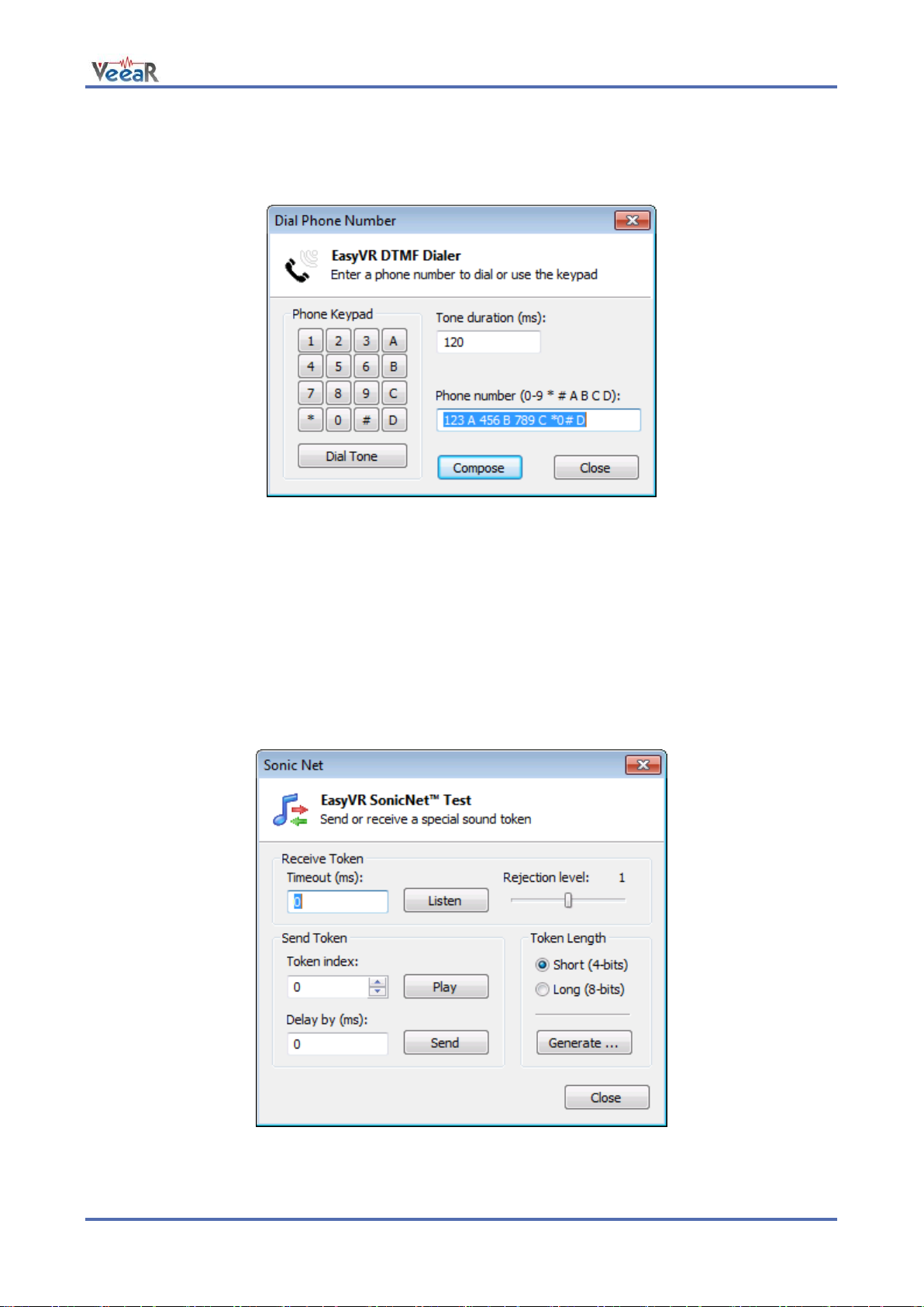
www.veear.eu
Phone Tones Generation (DTMF)
The EasyVR module is also capable of generating DTMF sounds. This feature can be tested by using the
“Dial Tones” command in the “Tools” menu.
Figure 6 – Interface for generating phone tones
The tone duration can be specified in increments of 40 ms (milliseconds). The dial tone has a fixed duration
of 3 seconds (its duration can be modified when programming the EasyVR).
Testing SonicNetTM
Another feature available from the “Tools” menu is the “SonicNet”, a wireless communication protocol based
on transmission and detection of special sequences of tones, called “tokens”.
Two kinds of tokens can be selected: a short version, with up to 16 different tokens, and a long version that
provides up to 256 tokens.
Figure 7 – Interface for testing SonicNet features
The EasyVR module can listen for incoming tokens continuously, or for as long as about 28 seconds
User Manual (1.0.11) EasyVR 3 61
Page 62

www.veear.eu
(specified with a granularity of around 27.5 ms). Another parameter for token detection is the rejection level
that specifies the receiver sensitivity: higher rejection means lower sensitivity that is a lower detection rate,
and vice-versa.
When the timeout parameter is set to 0, the module will listen continuously and you can use the “Play” button
to send a token from your PC soundcard and the “Stop” button to stop listening.
Figure 8 - Modified interface during continuous listening
A prompt window will display the current state of token detection:
Tokens may also be transmitted from the module with the “Send” button. An optional delay parameter can be
used to indicate that the token will be mixed with the next sound played from the Soundtable, after the
specified amount of time since the playback begins. In this case the SonicNet dialog will close to let you
choose a sound to play back.
Note: If you want to mix tokens with a compressed audio sample, you must use a compression
scheme with a sample rate of 9.3kHz when building the Soundtable in the QuickSynthesisTM
tool.
If the delay is 0, the token is sent out immediately. Other values can be specified up to around 28 seconds of
delay (with a granularity of around 27.5 ms).
Finally, you can also export all the tokens of the specified length to some folder on your PC as Wave files
(.WAV format) by using the “Generate…” button. You can then use those files to embed SonicNetTM tokens
into other software or external sound sources (such as portable players, CDs or DVDs, etc…)
62 EasyVR 3 User Manual (1.0.11)
Page 63

Compression Scheme
Available Time (8kHz 15% silence)
Available Time (9.3kHz 15% silence)
SX-2
8.7 minutes
7.5 minutes
SX-3
7.6 minutes
6.6 minutes
SX-4
6.8 minutes
5.9 minutes
SX-5
6.1 minutes
5.2 minutes
SX-6
5.6 minutes
4.8 minutes
4-bit ADPCM
87 seconds
N/A
8-bit PCM
45 seconds
38 seconds
Using Custom Data
www.veear.eu
Figure 9 - Export of 4-bit tokens
Sound Table
The EasyVR module can play one of the sounds or sentences saved on its internal flash memory. A
predefined “beep” sound is also always available, even when no sounds have been downloaded to the
module.
The custom sounds are organized in a so-called “sound table” that users can prepare and build with the
special QuickSynthesisTM tool. Please refer to this application’s own manual for details about the creation of
a sound table. Let’s summarize the basic steps here:
Prepare the audio files you want to include in the sound table in WAV format, uncompressed 16-bit
22050Hz mono. To create the sound files you may use a free software like Audacity for example
(http://audacity.sf.net)
Open Sensory’s QuickSynthesisTM 5 and create a new project, specifying “RSC4 family”
Add your WAV files and specify one of the supported compression scheme (see table below)
Optionally add sentences, by combining basic WAV sounds. That allows you to save memory when
you have speech audio files, if they share some pieces (like “You said” + “One”, “You said” + “Two”,
and so on)
Build the project with QuickSynthesisTM and use default settings (“Build linkable module”, “Load in
CONST space”, “Load above or at: 0”). You will be asked to recompress new or modified sound files,
just confirm and proceed
Now save your project and build it once again, so that the EasyVR Commander will see that your
build is up to date.
The audio compression formats supported by the EasyVR module (from highest to lowest compression rate):
User Manual (1.0.11) EasyVR 3 63
Page 64

www.veear.eu
For audio file containing speech, the SX-3 compression is usually a good choice. If you need higher quality
try lower compression rates. Please note that due to the sampling rate used, the audio files cannot contain
very high frequencies (less than half the sampling rate).
Figure 10 - External tool for creating a Soundtable
Note: Only one Soundtable can be downloaded to the EasyVR module, so make sure you
include all the sounds you want to use in a single project.
Speaker Independent Custom Vocabularies
The set of built-in Speaker Independent recognition vocabularies can be expanded with custom grammars,
that you can create with the QuickT2SITM tool (a separate license is required to use the software).
When you create a QuickT2SITM project, you are presented with a list of words or short phrases (also called
“commands”) and an optional trigger word/phrase. The so-called “trigger” is a special set that contains only
one word or phrase, with an improved recognition performance, that is used as an entry point for any vocal
interaction with a device that is continuously listening to the user’s voice.
If you need to use a trigger word, it is important to carefully choose it so that it has good performance, with
very few unintended activations and a high recognition rate. When the user says the trigger word followed by
a command, the system can discard unintended activations when the trigger is not followed by a command
within a short amount of time (usually around 3 seconds). Moreover, there is only one trigger word to listen
to, instead of a list of several commands, so the chance to pick up a random command from background
noise or talk is also lower, when using a trigger word.
For assistance on using the QuickT2SI™ Software, please refer to the software help file.
64 EasyVR 3 User Manual (1.0.11)
Page 65

www.veear.eu
Figure 11 - External tool for custom vocabularies
Several projects can also be combined together if they are using the same acoustic model (language data)
using the Acoustic Model Combiner included with the tool. This is useful if you have many command
vocabularies, in order to save space in the EasyVR memory.
Updating Custom Data
Once the sound table and/or custom recognition grammars have been created, they can be processed by
the EasyVR Commander and downloaded to the module. Note that you must first disconnect from the
module and do the steps required to start it in “boot-mode” (see the section Flash Update).
Now the command “Update Custom Data” is enabled, either on the toolbar or the “File” menu, and it can be
used to start the update process. First you are required to list all the QuickSynthesisTM and QuickT2SITM
projects you want to use. A new file containing the specified custom data will be generated and the contents
will be displayed, so that you can verify them before updating the module.
Note: The projects must have been built already with the QuickSynthesisTM or the QuickT2SITM
tool, before the custom data generation can be completed successfully. If a recent build is not
available you will receive a warning message, the project files can be opened in their respective
tools and a fresh build started (make sure the project file has been saved before the build).
Once back in the EasyVR Commander the project can be reloaded by pressing the “Refresh” button. If the
process completes successfully, the “Download” button will be enabled and the flash update process can
start.
The default format of generated data is suitable for the EasyVR 3. For previous versions of the module or the
shield please make sure to check the option “Old Format (EasyVR 2.0)”.
User Manual (1.0.11) EasyVR 3 65
Page 66

www.veear.eu
6
Figure 12 – Interface to build and download custom data
The download process will connect at a higher speed to the EasyVR module, so the “bridge” program
running on your host device might not work (in particular Robonova and Basic Stamp cannot be used for this
purpose) and you might need a true “serial adapter”.
The full speed used is 230400 bps, but the option “Slow transfer” can be used to reduce it to 115200, for
better compatibility with slower serial adapters6. One adapter that can go to full speed is the QuickUSB
cable. Otherwise any USB/Serial adapter with TTL/CMOS interface can be used for updating the flash. The
EasyVR Shield can be used for the download, provided that the mode jumper is in UP or LEO position.
Note: Every download will overwrite the previously transferred custom data.
After the download completes, a new connection can be established with the EasyVR module (in “normalmode”) and the new sounds will be displayed by the EasyVR Commander, in the special group “SoundTable”
(the last one in the list with a yellow icon). They can be played back and tested using the “Play Sound”
command on the toolbar or in the “Tools” menu. See also how to do that in your application in the code
example Use custom sound playback.
Custom grammars will be displayed just after the built-in word sets and they work exactly the same way.
Trigger words, when specified, will have their own vocabulary with only one entry. You can test and use the
custom trigger and command grammars as you do with the built-in ones.
Note: The built-in trigger word set is handled in a special way, as it is active also when
recognizing from the first user defined command group. This is the only case where SD and SI
commands are mixed together and does not apply to custom trigger vocabularies.
Arduino UNO (and other boards with USB/Serial adapter based on ATMEGA8U2) need the option “Slow
transfer” enabled
66 EasyVR 3 User Manual (1.0.11)
Page 67

www.veear.eu
Updating Firmware
The EasyVR firmware can be updated in a similar way to custom data by using the command “Update
Firmware...” from the “Help” menu. Note that you must first disconnect from the module and do the steps
required to start it in “boot-mode” (see the section Flash Update).
The specified file will be verified as an official firmware release and basic version information will be
displayed. If the firmware passes the verification step, then the “Download” button will be enabled.
Figure 13 - Interface for updating EasyVR firmware
Note: After a new firmware is downloaded to the module, the custom data already present is
erased and it must be downloaded again if necessary.
User Manual (1.0.11) EasyVR 3 67
Page 68

www.veear.eu
A SIDE
B SIDE
USB Type A Plug
(male connector)
Hirose DF11-6DS-2C
(female connector)
Pin
Type
Name
Description
1
I
RXD
Asynchronous Data Receive line
2
O
RTS#
Request To Send flow control line
3
GND
GND
Power and signal ground
4
Power
VCC
5V power output (USB VBUS)
5
O
TXD
Asynchronous Data Transmit line
6
I
CTS#
Clear To Send flow control line
QuickUSB Adapter Cable
Product Description
The QuickUSB is an USB-to-UART adapter cable, easy to
use and supported on all the major operating systems.
It plugs into a standard USB port and brings all the UART
signals to a convenient 6-pin 2mm pitch female connector
(Hirose DF11 Series).
QuickUSB Features
USB 2.0 Full Speed interface
Full UART (RX/TX and RTS/CTS) at 3.3V
Data transfer rates from 300 bps to 3 Mbps
Extended operating temperature range: -40°C to 85°C
Cable Length: 1.8 m
Technical Specifications
Drawings and Schematics
Pin Description
68 EasyVR 3 User Manual (1.0.11)
Page 69

Symbol
Parameter
Min
Typ
Max
Unit
VCC
DC Power Output (VBUS) *
4.5
5.0
5.5 V Ta
Ambient Operating Temperature Range
-40
25
85
°C
Symbol
Parameter
Min
Typ
Max
Unit
VIH
Input High Voltage
1.5 3.3
V
VIL
Input Low Voltage
0.0 1.0
V
Symbol
Parameter
Min
Typ
Max
Unit
VOH
Output High Voltage (IOH = -1 mA)
2.2
2.7
3.2 V VOL
Output Low Voltage (IOL = 2 mA)
0.3 0.5
V
Operating Conditions
(*) Output current might be limited by USB Host and internal adapter settings
Electrical Characteristics
These are applicable to pins RXD, CTS.
These are applicable to pin TXD, RTS.
www.veear.eu
QuickStart Instructions
Software Setup
The first time you want to use the QuickUSB you need to install the required software drivers for your
Operating System. Please follow this procedure (one-time only):
1. Plug the USB end of the cable to your PC and leave the other end unconnected
2. If you have a recent OS version please allow the system to search for updated drivers:
a. If the setup was successful, unplug the cable, the procedure is complete
b. If the setup failed, unplug the cable and continue to the next step
3. Download the latest official drivers for your OS version from the FTDI VCP Drivers page
4. Run the driver setup package, or follow any alternate installation procedure accompanying the
download
5. After the software setup is complete go back to step 1 above, the OS should now be able to find the
required drivers automatically
Using the Adapter
Once the required software drivers are correctly installed and configured by the Operating System, you
should not need to repeat the above procedure anymore.
Just plug the cable on the target board first, then plug the USB connector to a free port on your PC.
The adapter will be visible as a new USB Serial Port device and a virtual COM port on Windows. This COM
port number is the one to use with the EasyVR Commander.
User Manual (1.0.11) EasyVR 3 69
Page 70

www.veear.eu
How to get support
Please feel free to contact us with any questions, queries or suggestions.
If your question is about technical support or troubleshooting for one of our products, we kindly ask you to
first check our FAQ for a possible solution: http://www.veear.eu/faq
If you cannot find an existing solution on the FAQ, please contact us using the contact form on our website at
http://www.veear.eu/support. The more detail you provide, the better support we can give.
VeeaR © RoboTech srl, all rights reserved.
All VeeaR branded boards and software are manufactured by RoboTech srl
RoboTech srl assumes no responsibility for any errors, which may appear in this manual. Furthermore, RoboTech srl
reserves the right to alter the hardware, software, and/or specifications detailed herein at any time without notice, and
does not make any commitment to update the information contained herein. RoboTech srl products are not authorized
for use as critical components in life support devices or systems.
70 EasyVR 3 User Manual (1.0.11)
 Loading...