

Page 1
VECTOR™
Operating & Operator Maintenance Instructions
Version 0.3
LEICA VECTOR™
50
403020
USMC VECTOR 21
Shop for Vectronix products online at:
1.877.766.5412
www.SCOUTBASECAMP.com
Page 2
VECTOR ™- USMC VECTOR 21-V.0.3
2
For safe use of the VECTOR, please note the detailed safety
directions included in this manual.
© 2004 Vectronix AG, ® All rights reserved.
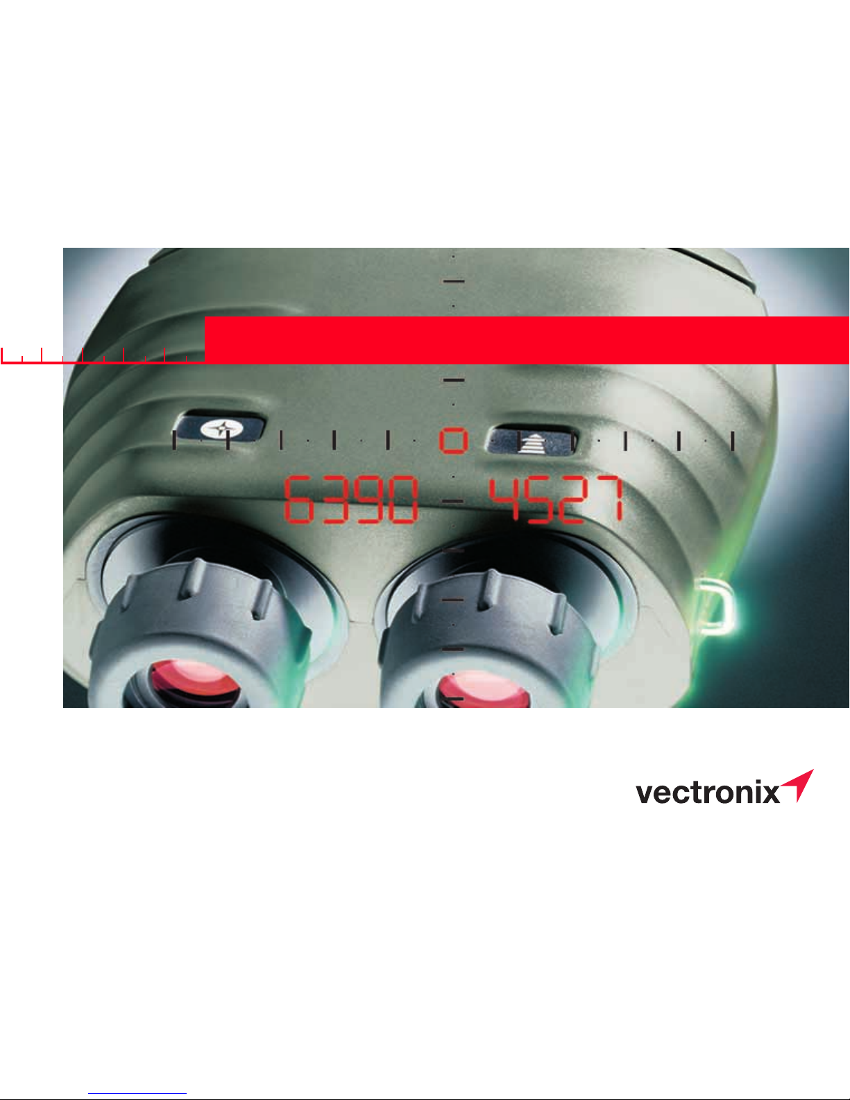
VECTOR™
VECTOR™
As its name implies, the
VECTOR measures the polar
vector from your position to the
target object.
Congratulations on purchasing
your VECTOR.
VECTOR = 4 instruments in 1:
• Binoculars
Superb optics in a robust,
watertight, rubber-armoured
casing.
• Digital Compass
Displays magnetic azimuth or
grid azimuth in degrees or
mils.
• Laser Rangefinder
Measures from 5 m to over
10 km (depending on visibility
and nature of target objects).
• Inclinometer
Displays vertical angles
between -45° and +45°.
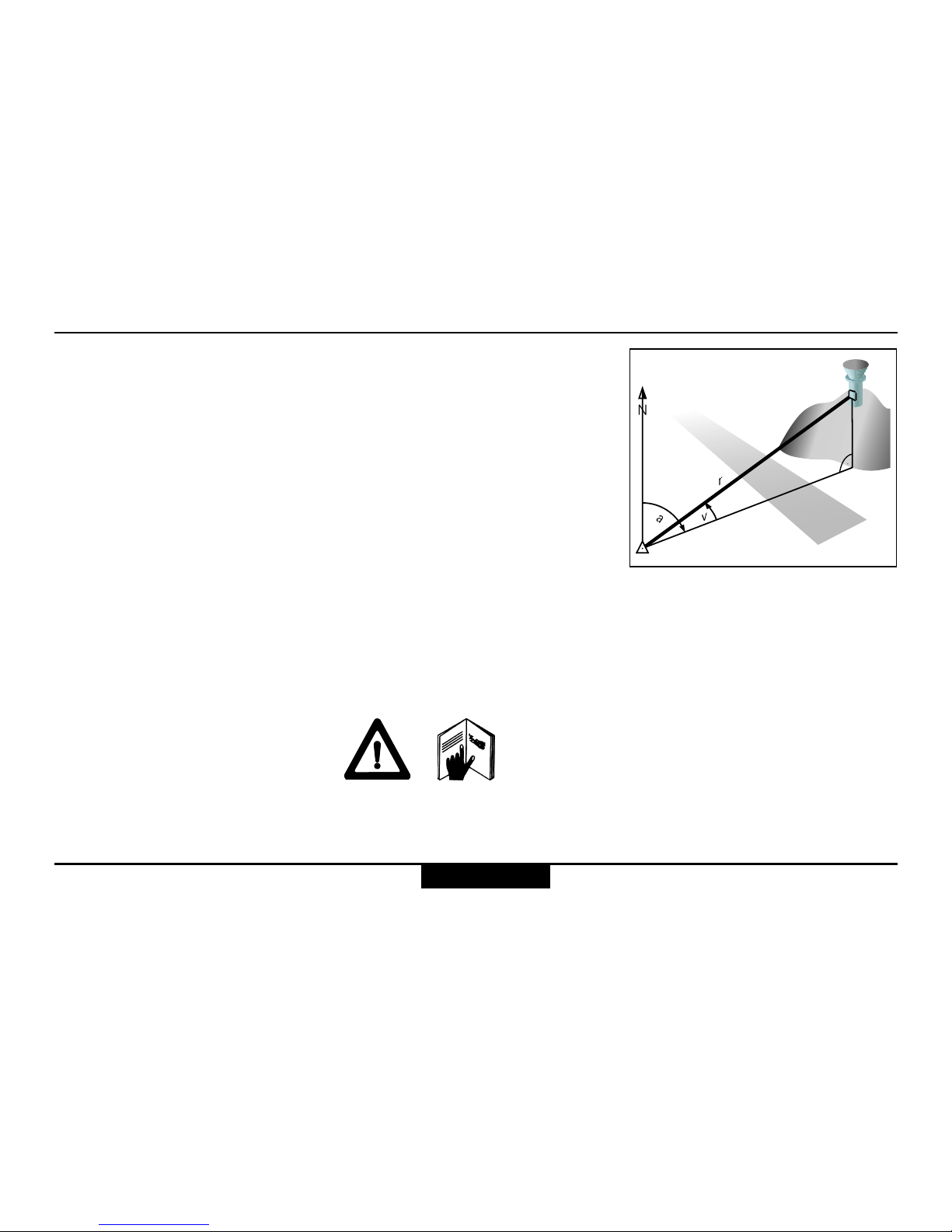
r Range (slope distance)
a Azimuth (bearing, horizontal
direction, angle between
north and object)
v Vertical angle (inclination,
elevation)
Shop for Vectronix products online at:
1.877.766.5412
www.SCOUTBASECAMP.com
Page 3

3
VECTOR ™- USMC VECTOR 21-V.0.3
Contents
Getting started ......................................................................................................................................... 6
Changing the battery .................................................................................................................... 6
Adjusting the neck strap ............................................................................................................... 7
Removing the neck strap .............................................................................................................. 7
Storing the VECTOR .................................................................................................................... 7
Eyepiece viewing distance ........................................................................................................... 8
Eye-base adjustment .................................................................................................................... 8
Dioptric adjustment ....................................................................................................................... 8
Using the VECTOR ....................................................................................................................... 9
Distance measurements ....................................................................................................................... 10
Factors affecting measurement range ....................................................................................... 10
Distance measurement (slope distance).................................................................................... 11
Multiple object measurement .....................................................................................................12
Data transfer for multiple measurements ................................................................................... 13
Combined measurement with data transfer (slope distance, azimuth, inclination) .................. 14
Horizontal dist. and height difference between your position and a remote object .................. 15
Distance between two objects ....................................................................................................16
Horizontal and vertical distance between two objects ............................................................... 17
Azimuth and inclination measurement ............................................................................................... 18
Factors influencing azimuth accuracy ....................................................................................... 18
Azimuth measurement ................................................................................................................ 19
Contents
Shop for Vectronix products online at:
1.877.766.5412
www.SCOUTBASECAMP.com
Page 4

VECTOR ™- USMC VECTOR 21-V.0.3
4
Combined azimuth and inclination angle measurement ............................................................ 20
Azimuth and horizontal distance between two objects .............................................................. 21
Fall of shot - FOS ....................................................................................................................... 22
Data transfer .......................................................................................................................................... 24
Connecting/disconnecting the interface cable ........................................................................... 24
Cable configuration to PLGR...................................................................................................... 25
Interface parameters .................................................................................................................. 25
Cable configuration to PC .......................................................................................................... 26
Interface parameters .................................................................................................................. 26
Data transfer format for PC ........................................................................................................ 27
Configuration ......................................................................................................................................... 28
Making adjustments .................................................................................................................... 28
Electronic reticle ......................................................................................................................... 29
Night vision device ...................................................................................................................... 29
Using the VECTOR with a night vision device ........................................................................... 30
Settings................................................................................................................................................... 32
Setting the measurement units .................................................................................................. 32
Range gate ................................................................................................................................. 33
Declination compensation .......................................................................................................... 34
Declination display ...................................................................................................................... 34
Declination setting/correction ..................................................................................................... 35
Contents
Contents
Shop for Vectronix products online at:
1.877.766.5412
www.SCOUTBASECAMP.com
Page 5

5
VECTOR ™- USMC VECTOR 21-V.0.3
Compass calibration ................................................................................................................... 36
General instructions .................................................................................................................... 36
Operator guidance ...................................................................................................................... 37
Calibration procedure (hand held).............................................................................................. 38
Calibration procedure (on tripod) ...............................................................................................39
Setting the mode of the data interface (RS 232) for Rockwell PLGR+96 / PLGR II ................. 41
Setting the PLGR+96.................................................................................................................. 42
Built-in-Test ................................................................................................................................. 43
Setting VECTOR back to factory settings .................................................................................. 44
Troubleshooting .................................................................................................................................... 45
Safety notices ........................................................................................................................................ 51
Care/cleaning ......................................................................................................................................... 53
Technical data ........................................................................................................................................ 54
Equipment .............................................................................................................................................. 57
Shipping inventory ...................................................................................................................... 57
Accessories................................................................................................................................. 58
Reticle ......................................................................................................................................... 59
Reticle with Binocular Enhancer ................................................................................................ 60
Options ........................................................................................................................................ 61
Customer service .................................................................................................................................. 62
Contents
Contents
Shop for Vectronix products online at:
1.877.766.5412
www.SCOUTBASECAMP.com
Page 6
VECTOR ™- USMC VECTOR 21-V.0.3
6
Getting started
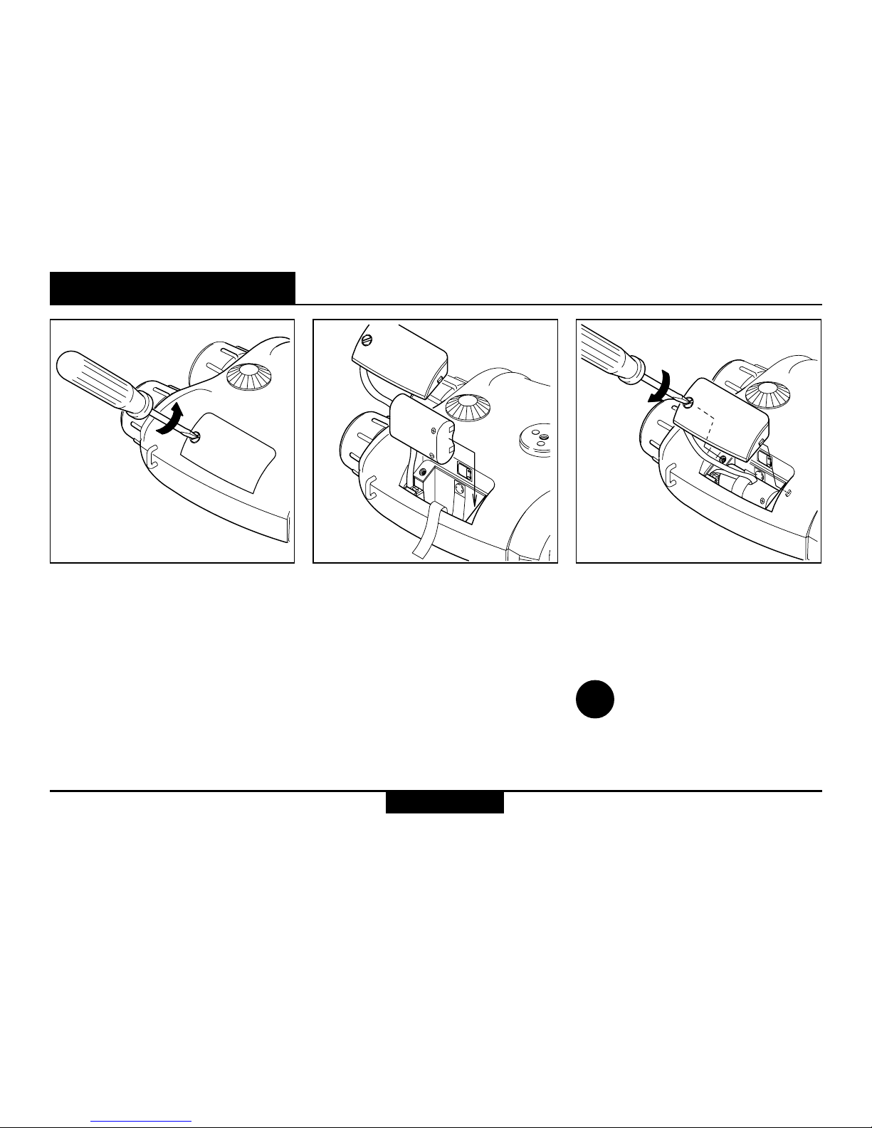
Changing the battery
Open the battery compartment
using a suitable tool, or a coin.
Insert a 6V lithium battery, type
2CR5 or equivalent.
Ensure that the drawing ribbon
lies above the securing tape of
the battery cover. Keep the
battery cover seals and the
instrument case clean.
Refit the battery cover and retighten the screw.
The VECTOR monitors the
battery’s condition. If the display
shows 'Lo batt', this indicates
that the battery is used up. You
can still get readings, but the
battery needs to be replaced
soon.
i
The 'Lo batt' display may also
appear under cold conditions,
since low temperature reduces
the battery performance.
Remove the VECTOR
battery before a prolonged
period of non-use.
Use non-magnetic batteries
only!
Getting started
Shop for Vectronix products online at:
1.877.766.5412
www.SCOUTBASECAMP.com
Page 7
7
VECTOR ™- USMC VECTOR 21-V.0.3
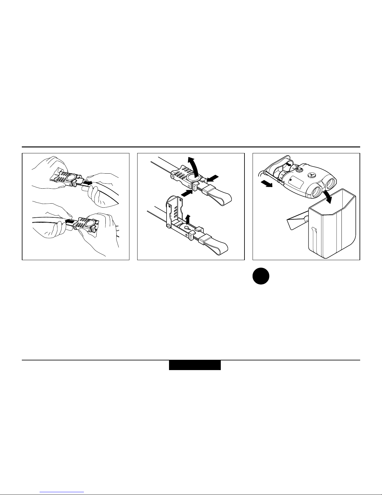
To protect from dirt:
Always fit the eyepiece
cover and keep your VECTOR
in its pouch when not in use.
Adjust the length of the neck
strap by pulling the strap slowly
but firmly around the back of the
catch.
Open both catches:
Squeeze the two clips together
and lift the cover. Remove the
strap ends and pull them
through the lugs on the
VECTOR.
Storing the VECTORRemoving the neck strapAdjusting the neck strap
i
Getting started
Shop for Vectronix products online at:
1.877.766.5412
www.SCOUTBASECAMP.com
Page 8
VECTOR ™- USMC VECTOR 21-V.0.3
8
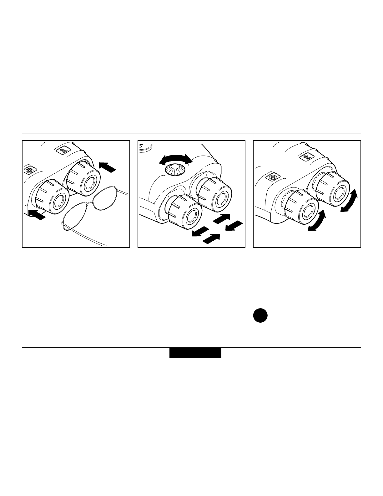
Eyepiece viewing distance Dioptric adjustmentEye-base adjustment
Turn the adjusting knob until the
left and right fields of view fuse
to form a circular image.
When using the VECTOR with
glasses, push the eyecups fully
inwards.
When using the VECTOR
without glasses, pull the
eyecups out to the stop.
Sight on an object farther than
100 m away and rotate the
eyepieces to obtain a sharp
image. Standard setting:
0 dioptres.
If the VECTOR is being
used by a number of different people, remember your
personal dioptric setting.
i
Getting started
+
-
+
-
+
-
-
+
Shop for Vectronix products online at:
1.877.766.5412
www.SCOUTBASECAMP.com
Page 9
9
VECTOR ™- USMC VECTOR 21-V.0.3
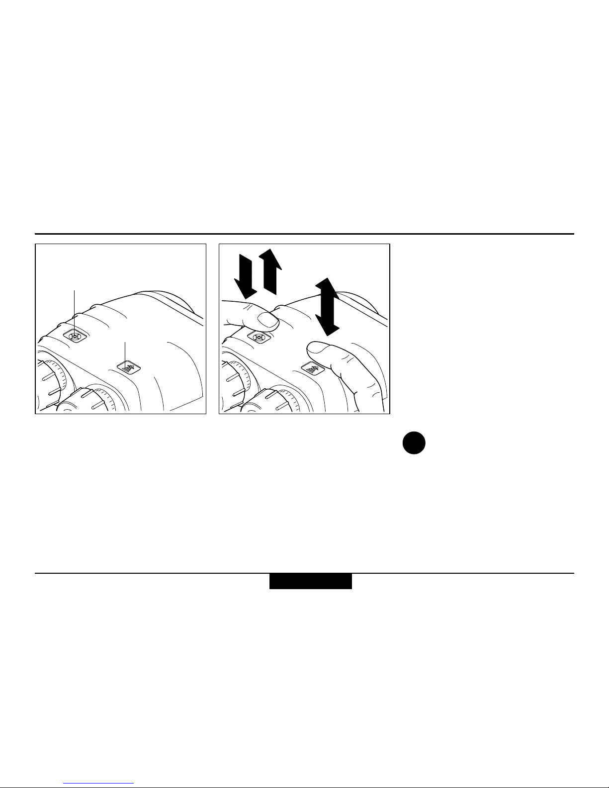
Using the VECTOR
The VECTOR is operated
entirely by means of the keys on
the top of the casing.
Key operation is indicated by
the following symbols:
Downward arrow: press and
hold down the key.
Upward arrow: release the key
Double arrow: press and release
the key (click)
Double arrow plus a number:
Press and release the key in rapid succession (e.g. triple click)
Sight the object to be measured
using the pointing circle or
reticle (optional).
Hold the VECTOR steady during
measurement.
The VECTOR displays the
measurement result, then
switches itself off automatically
after a few seconds.
You can prolong the
display period by holding
down the measuring key while
the result is displayed.
Azimuth key
Distance key
i
Getting started
3x
Shop for Vectronix products online at:
1.877.766.5412
www.SCOUTBASECAMP.com
Page 10
VECTOR ™- USMC VECTOR 21-V.0.3
10
Distance measurements
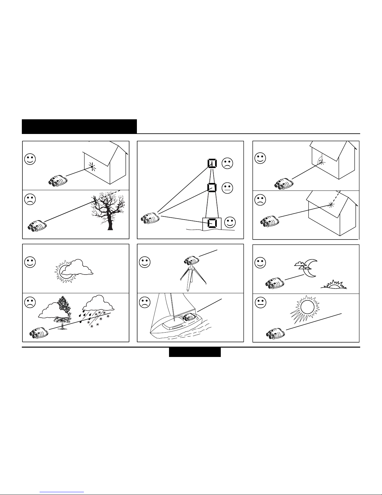
Factors affecting measurement range
Reflective properties Size of the target Oblique surfaces
Atmospheric conditions
Vibration Lighting conditions
Distance measurements
Shop for Vectronix products online at:
1.877.766.5412
www.SCOUTBASECAMP.com
Page 11
11
VECTOR ™- USMC VECTOR 21-V.0.3
Distance measurements
Distance measurement (slope distance)
Press and hold the distance key;
the pointing circle appears in the
field of view.
Turning the pointing circle
on and off: see page 29.
Sight the pointing circle on the
object.
Hold the VECTOR steady as
you release the distance key.
Read off the distance.
If "----" appears in the display, the
object lies outside the measuring
range, or measuring conditions
are poor (see page 10).
Setting measurement units
and range gate: see pages
32, 33.
i
i
Shop for Vectronix products online at:
1.877.766.5412
www.SCOUTBASECAMP.com
Page 12
VECTOR ™- USMC VECTOR 21-V.0.3
12
Distance measurements
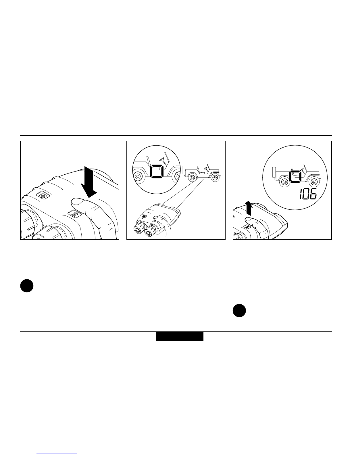
Multiple object measurement
Up to 3 separate distances can
be obtained with a single measurement, for example when:
• the laser beam passes through
objects in front of the main
target (bushes, shrubs, etc.)
• there are reflective objects
behind the main target
(mountains, etc.)
The distance display blinks for a
few seconds after a multiple
distance measurement. Click the
distance key repeatedly to
obtain all the measured
distances in succession.
This feature is always
activated. The order of the
displayed ranges is: closest,
strongest between first and last,
and furthest detected echo.
Sight on the most visible portion
of the object. Operate the
VECTOR as described under
”distance measurement”.
i
Shop for Vectronix products online at:
1.877.766.5412
www.SCOUTBASECAMP.com
Page 13

13
VECTOR ™- USMC VECTOR 21-V.0.3
Distance measurements
Data transfer for multiple measurements
For data transfer via PLGR
when measuring multiple targets
proceed as follows:
• Set the communication mode
to "PLGr Con" as described
before.
• Press the distance key until
the desired measurement is
displayed.
• Now press the azimuth key to
transfer this data.
See page 12 for details about
"Multiple object measurement".
Shop for Vectronix products online at:
1.877.766.5412
www.SCOUTBASECAMP.com
Page 14
VECTOR ™- USMC VECTOR 21-V.0.3
14
Distance measurements
Combined measurement with data transfer (slope distance, azimuth, inclination)
Measurement data is transmitted
via the (optional) interface cable
immediately after the measurement is taken (see page 27).
It is not possible to store measurement data in the VECTOR
itself.
Hold down both keys simultaneously (or the remote fire button);
the pointing circle appears,
together with the current azimuth.
Sight the object with the pointing
circle.
Release both keys (or the
remote fire button) while holding
the VECTOR steady.
The azimuth appears at the left
and the slope distance at the
right of the field of view.
The inclination angle is not
displayed, but it is sent via the
data interface.
Setting measurement units:
see page 32.
i
Shop for Vectronix products online at:
1.877.766.5412
www.SCOUTBASECAMP.com
Page 15
15
VECTOR ™- USMC VECTOR 21-V.0.3
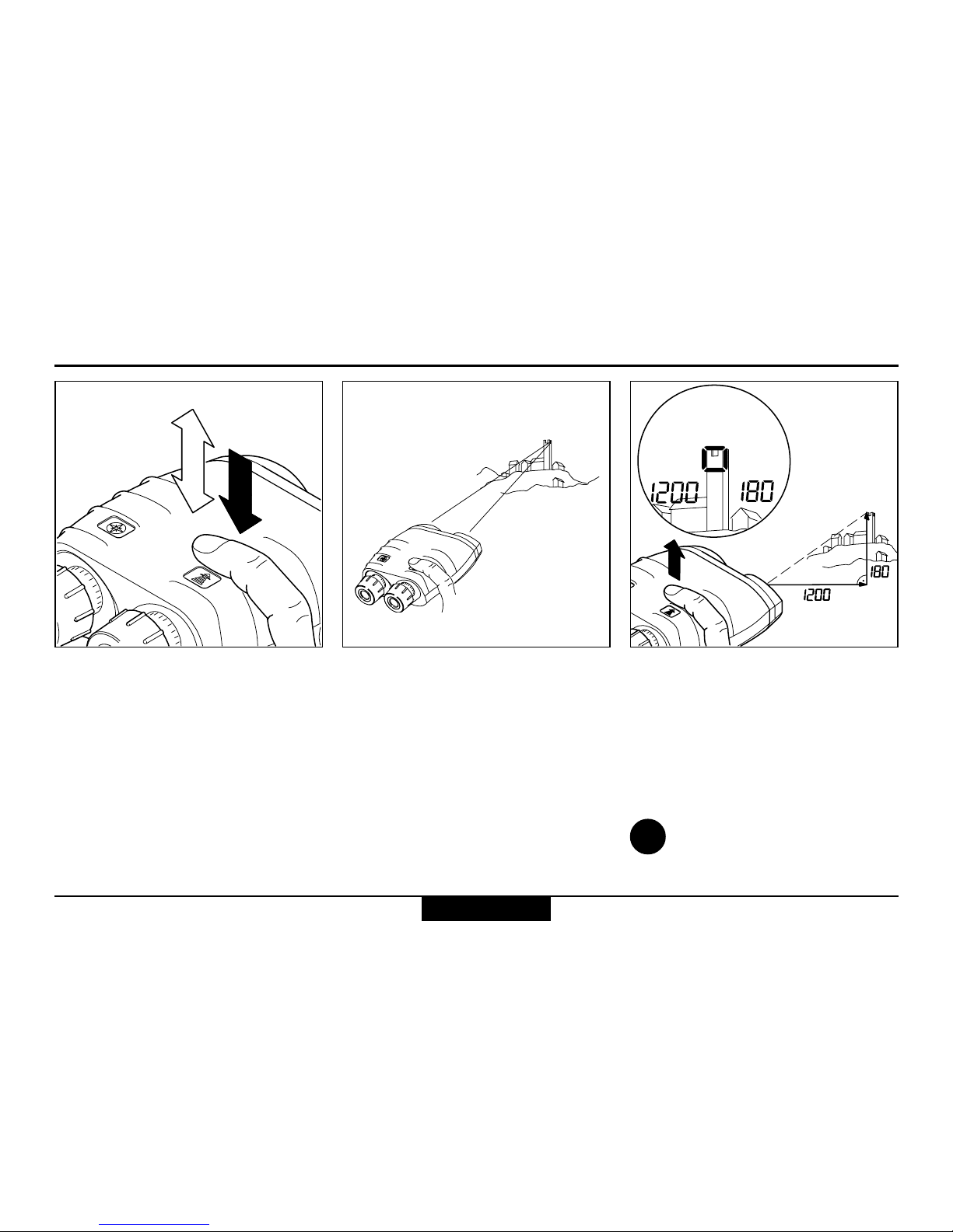
Distance measurements
Horizontal dist. and height difference between your position and a remote object
Click the distance key once,
then press and hold it down.
The pointing circle appears.
Sight the object with the pointing
circle.
Release the distance key while
holding the VECTOR steady.
The horizontal distance appears
at the left and the height difference at the right of the field of
view.
Setting measurement units:
see page 32.
i
Shop for Vectronix products online at:
1.877.766.5412
www.SCOUTBASECAMP.com
Page 16
VECTOR ™- USMC VECTOR 21-V.0.3
16
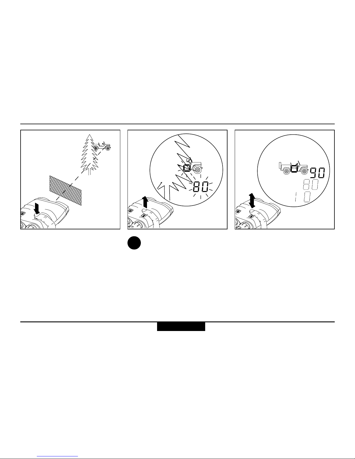
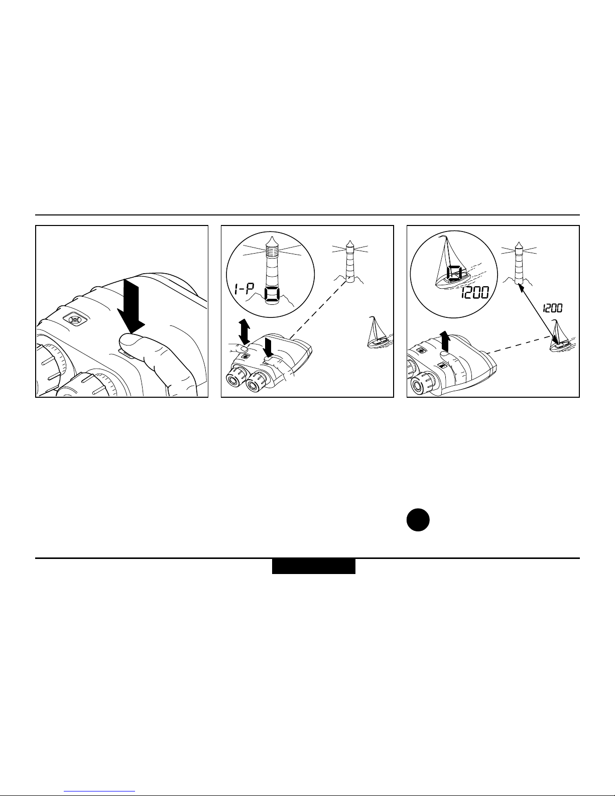
Distance measurements
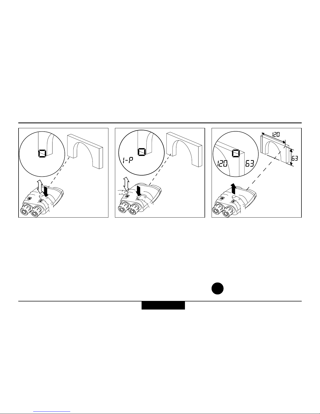
Distance between two objects
Press and hold the distance
key.
The pointing circle appears.
Sight the first object with the
pointing circle.
Click the azimuth key while
holding the VECTOR steady.
The first object measurement is
confirmed (1-P = first point).
Sight the second object with the
pointing circle.
Release the distance key while
holding the VECTOR steady.
The distance between the two
objects is displayed.
Setting measurement units:
see page 32.
i
Shop for Vectronix products online at:
1.877.766.5412
www.SCOUTBASECAMP.com
Page 17
17
VECTOR ™- USMC VECTOR 21-V.0.3
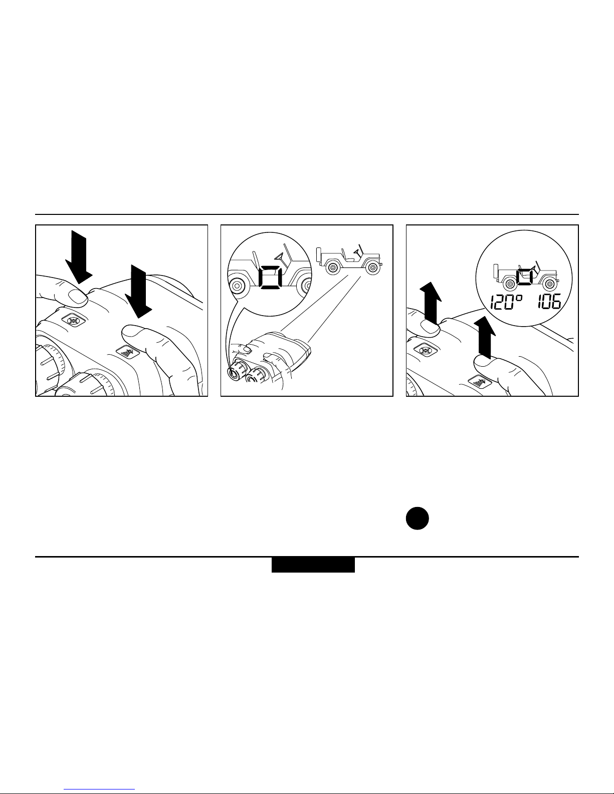
Distance measurements
Horizontal and vertical distance between two objects
Click the distance key once,
then press and hold it down.
The pointing circle appears.
Sight the first object with the
pointing circle.
Click the azimuth key while
holding the VECTOR steady.
The first object measurement is
confirmed (1-P = first point).
Sight the second object with the
pointing circle.
Release the distance key while
holding the VECTOR steady.
The horizontal distance appears
at the left and the vertical
distance at the right of the field
of view.
Setting measurement units:
see page 32.
i
Shop for Vectronix products online at:
1.877.766.5412
www.SCOUTBASECAMP.com
Page 18
VECTOR ™- USMC VECTOR 21-V.0.3
18
Azimuth and inclination measurement
Azimuth and inclination measurement
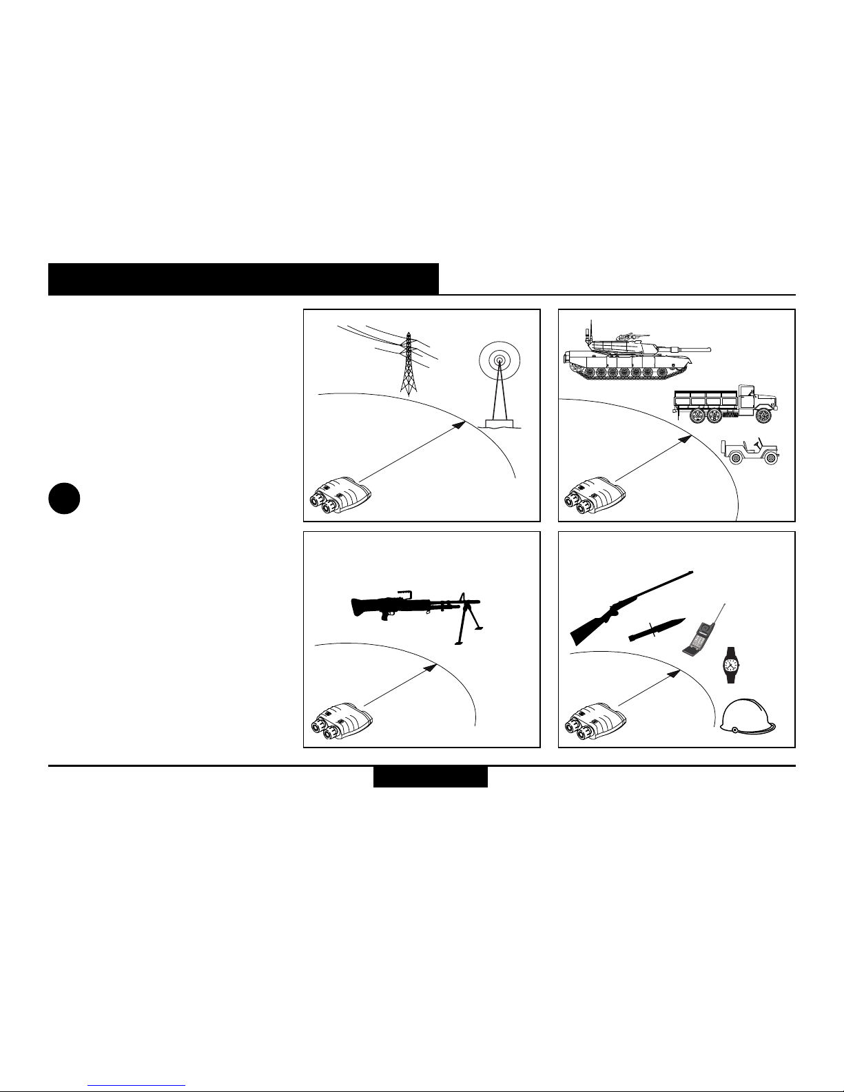
Factors influencing azimuth accuracy
The VECTOR has a digital
compass that works similarly to
a magnetic compass. Metal
objects and magnetic fields can
cause errors in directional
readings. Nonmagnetic metals
and alloys do not affect the
compass readings.
Countermeasures:
• Use non-magnetic batteries
only!
• Calibrate the compass (see
pages 36–40) after every
battery change.
• Observe the minimum safe
distances shown opposite
when making azimuth
measurements or calibrating
the compass:
55 m
10 m
2 m
0.5 m
i
Shop for Vectronix products online at:
1.877.766.5412
www.SCOUTBASECAMP.com
Page 19
19
VECTOR ™- USMC VECTOR 21-V.0.3
Azimuth and inclination measurement
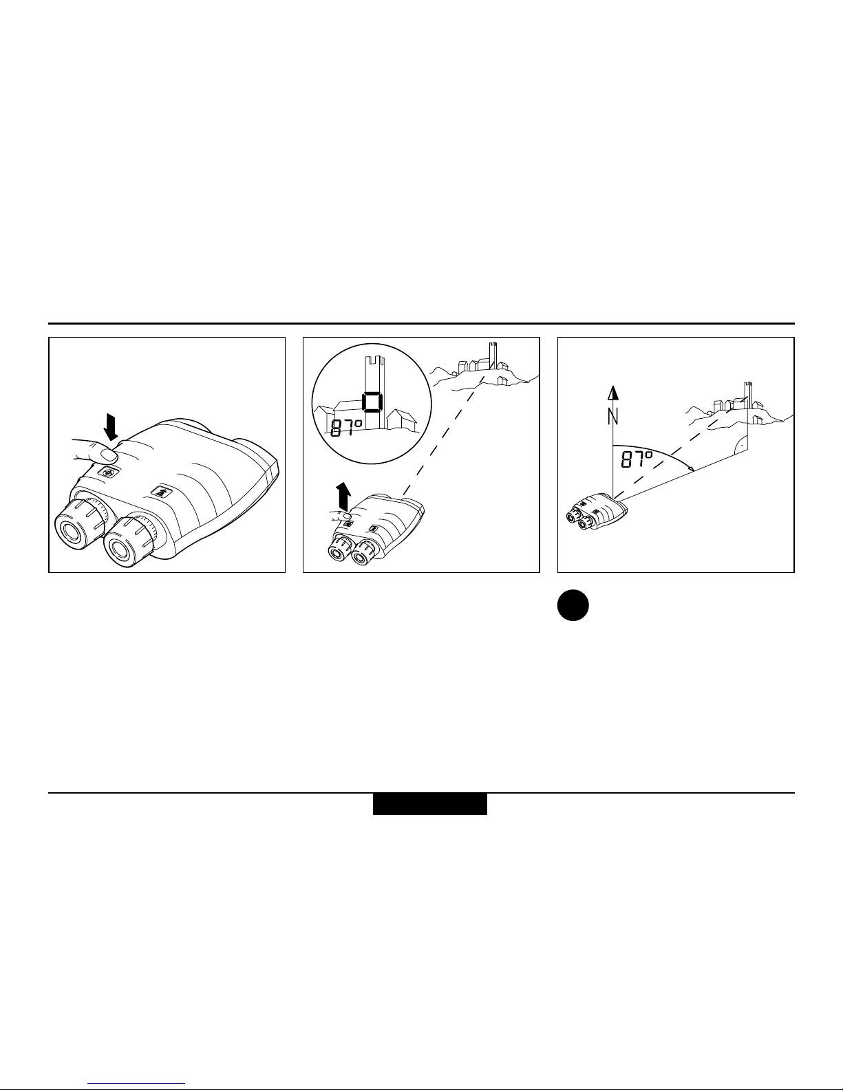
Azimuth measurement
Press and hold the azimuth key.
The pointing circle appears,
together with the current azimuth.
The display updates continuous
azimuth twice per second.
Sight the object with the pointing
circle, then release the azimuth
key while holding the VECTOR
steady.
The most recently measured
azimuth is displayed.
Setting measurement units:
see page 32.
i
Shop for Vectronix products online at:
1.877.766.5412
www.SCOUTBASECAMP.com
Page 20
VECTOR ™- USMC VECTOR 21-V.0.3
20
Azimuth and inclination measurement
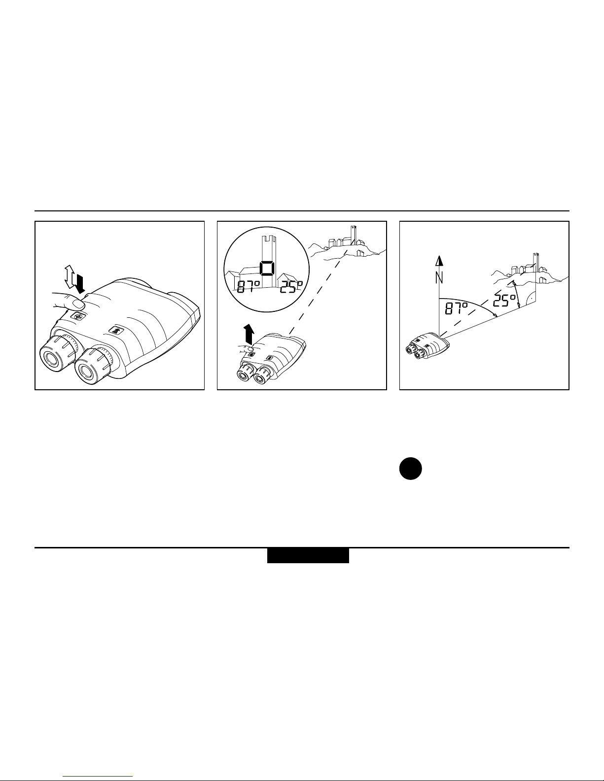
Combined azimuth and inclination angle measurement
Click the azimuth key once, then
immediately press and hold it
down.
The following items appear in
the field of view:
• the pointing circle
• the current azimuth at the left
• the current angle of inclination
at the right.
Sight the object with the pointing
circle, then release the azimuth
key while holding the VECTOR
steady.
The azimuth and angle of
inclination to the object are
displayed.
Setting measurement
units: see page 32.
i
Shop for Vectronix products online at:
1.877.766.5412
www.SCOUTBASECAMP.com
Page 21

21
VECTOR ™- USMC VECTOR 21-V.0.3
Azimuth and inclination measurement
Azimuth and horizontal distance between two objects
Press and hold the azimuth key.
The pointing circle appears,
together with the current
azimuth.
Sight the first object with the
pointing circle.
Click the distance key (> 0.5 s)
while holding the VECTOR
steady.
The first object measurement is
confirmed (1-P = first point).
Sight the second object with the
pointing circle.
Release the azimuth key while
holding the VECTOR steady.
The azimuth appears at the left
and the horizontal distance at
the right of the field of view.
Setting measurement units:
see page 32.
i
Shop for Vectronix products online at:
1.877.766.5412
www.SCOUTBASECAMP.com
Page 22

VECTOR ™- USMC VECTOR 21-V.0.3
22
Fall of shot - FOS
Azimuth and inclination measurement
Click the azimuth key once, then
immediately press and hold it
down.
The following items appear in
the field of view:
• the current azimuth at the left
• the current angle of inclination
at the right
Sight the target with the
pointing circle. Click the distance key while holding the
VECTOR steady - "1-P"
appears.
Sight the FOS and release
azimuth key while holding the
VECTOR steady.
The corrections (L.. / r..,
A.. / d..) from FOS to target
appear first.
Shop for Vectronix products online at:
1.877.766.5412
www.SCOUTBASECAMP.com
Page 23

23
VECTOR ™- USMC VECTOR 21-V.0.3
i
The display time can be
extended, by holding down
the distance key during the time
the parameters are shown.
Click distance key to display
height correction (UP.. / dn..).
Click distance key to display
corrections again.
Example: If a shot is left and
short, the correction is r.. and
A.. with the appropriate value.
Azimuth and inclination measurement
Fall of shot - FOS (continued)
Shop for Vectronix products online at:
1.877.766.5412
www.SCOUTBASECAMP.com
Page 24

VECTOR ™- USMC VECTOR 21-V.0.3
24
Data transfer
Connecting/disconnecting the interface cable
On the underside of the VECTOR
is a socket for sending data to:
• personal computers or laptops
• modems
• fire control systems
• PLGR / DAGR
Our customer service will
be pleased to inform you
about special accessories for
transmitting and analysing data.
Caution
Incorrect handling can damage
the socket and optional
interface cable.
To plug:
Align the respective red markings
on the plug and socket.
Slide the plug carefully into the
socket until the locking
mechanism engages.
To unplug:
Grasp the plug grip
• between two fingers,
• draw it carefully back to the
stop to disengage the locking
mechanism,
• pull back a little harder until
the plug slips out of the socket.
i
Plug
Data transfer
Shop for Vectronix products online at:
1.877.766.5412
www.SCOUTBASECAMP.com
Page 25

25
VECTOR ™- USMC VECTOR 21-V.0.3
The optional interface cable is intended for connection to a PLGR
serial interface with a 15-pin plug.
Cable configuration to PLGR Interface parameters
Interface ......................... RS 232
Data
transmission .......... bidirectional
Baud rate .................... 9600 bps
Parity .................................. none
Data bits................................... 8
Stop bits ................................... 1
Handshake ......................... none
Data transfer
Shop for Vectronix products online at:
1.877.766.5412
www.SCOUTBASECAMP.com
Page 26

VECTOR ™- USMC VECTOR 21-V.0.3
26
The optional interface cable is intended for connection to a PC
serial interface with a 9-pin D plug.
Cable configuration to PC Interface parameters
Interface ......................... RS 232
Data
transmission .......... bidirectional
Baud rate .................... 9600 bps
Parity .................................. none
Data bits................................... 8
Stop bits ................................... 1
Handshake ......................... none
Data transfer
Shop for Vectronix products online at:
1.877.766.5412
www.SCOUTBASECAMP.com
Page 27

27
VECTOR ™- USMC VECTOR 21-V.0.3
Data transfer format for PC
A complete set of measurements therefore consists of 31
ASCII characters.
Before and after this continuous
string, a steady logic 1 is
transmitted while the VECTOR
is powered on.
Start character for measurement
value:
d (v) .............................. distance
a .................................... azimuth
e ................... angle of inclination
(elevation)
Start character for error report:
C ......................... compass error
R .......................... distance error
M ............................... instrument
(main board) error
Measurement value: 6 integer
digits or six-digit hexadecimal
error code.
The data transmitted comprises:
• distance in centimetres, with
0.5 m resolution
• azimuth and inclination in
milliradians (full circle =
6'283.2 mrad) and 0.2 mrad
resolution.
Every measurement (distance,
azimuth, inclination) is transmitted
as 10 ASCII characters; 11 for
distance data:
Checksum
End character
Measurement
value
Start character
Checksum: 2 hexadecimal
digits. These correspond to the
8 LSBs (least significant bits) of
the ASCII measurement value
and the start character.
End character: 1 position for line
feed (CR).
15'708/0
31'416/0
N
+30°
0/0
0/5'236
0/57'596
-30°
47'124/0
Z XXXXXX XY <CR>
Measurement examples:
Data transfer
Shop for Vectronix products online at:
1.877.766.5412
www.SCOUTBASECAMP.com
Page 28

VECTOR ™- USMC VECTOR 21-V.0.3
28
Configuration
Making adjustments
Configuration
Various instrument functions are
switched on and off via the
configuration menu.
Click the distance key five times
in rapid succession. "COn FIG"
appears followed by the current
range setting.
Click the azimuth key until the
desired function status appears.
The various functions are
described in detail on the
following pages.
Click the distance key five times
in rapid succession to save your
settings.
If the distance key is not correctly
clicked five times, the previous
settings remain unchanged and
”Old Conf” is displayed.
5x
5x
i
Shop for Vectronix products online at:
1.877.766.5412
www.SCOUTBASECAMP.com
Page 29

29
VECTOR ™- USMC VECTOR 21-V.0.3
Configuration
30
30
50
50
50
Electronic reticle Night vision device
Function: ErEt on/OFF
(Electronic Reticle)
The pointing circle is by default
OFF.
'ErEt' on is automatically
selected when 'niGt on' is
selected.
Function: niGt on/OFF
(Night Vision)
This function
• is normally turned OFF;
• reduces the display
brightness;
• is needed only when a night
vision device is attached.
Reticle
Pointing
circle
'niGt on' may appear if operation
is attempted with the function
'niGt on' during daylight
conditions.
Shop for Vectronix products online at:
1.877.766.5412
www.SCOUTBASECAMP.com
Page 30

VECTOR ™- USMC VECTOR 21-V.0.3
30
Configuration
Using the VECTOR with a night vision device
Remove binocular enhancer
when attached.
Remove the eyecup from the
right eyepiece.
Rotate the right eyepiece to
adjust it to 0 dioptres.
Then slide the eyepiece fully
inwards.
Adjust the eyepiece on the night
vision device to suit your
eyesight. Standard setting:
0 dioptres.
Remove the protective lens cap.
Rotate the lens counterclockwise all the way out
Fit the adapter, and screw it
firmly to the tripod bushing.
Shop for Vectronix products online at:
1.877.766.5412
www.SCOUTBASECAMP.com
Page 31

31
VECTOR ™- USMC VECTOR 21-V.0.3
Configuration
Carefully slide the night vision
device into the adapter.
Activate the ”niGt” function in
the configuration menu (see
page 28).
Using the VECTOR with a night vision device (continued)
At observation distances below
100 m, focus the night vision
device.
While sighting on an object with
the azimuth botton pressed and
held, adjust PVS-14 (diopter)
eyepiece and (objective) focus
in order to see the object and
azimuth readout clearly.
!
i
Adjust PVS-14 brightness (gain
control) to improve the image.
When you finish using the
night vision device, return
to the normal "niGt OFF" setting.
"niGt on" is displayed,
when function is activated
and used in daylight conditions.
Shop for Vectronix products online at:
1.877.766.5412
www.SCOUTBASECAMP.com
Page 32

VECTOR ™- USMC VECTOR 21-V.0.3
32
Settings
Setting the measurement units
Settings
Various angle and distance
measurement units may be set
via the configuration menu.
Click the azimuth key five times
in rapid succession.
”Unit SEtt” appears briefly,
followed by the measurement
units currently in use by the
VECTOR.
Click the distance key until the
desired units appear in the field
of view:
• at the left: angular unit in mils
or degrees
• at the right: distance unit in
metres (SI-Unit) or feet.
Click the azimuth key five times
in rapid succession to save your
preferred units.
If the azimuth key is not correctly
clicked five times, the previous
settings remain unchanged and
”Old Unit” is displayed.
5x
5x
Shop for Vectronix products online at:
1.877.766.5412
www.SCOUTBASECAMP.com
Page 33

33
VECTOR ™- USMC VECTOR 21-V.0.3
Settings
In certain applications, it may be
desirable to limit the closest
distance that the VECTOR will
measure.
Click the distance key three
times in rapid succession. ”diSt
GAtE“ appears, followed by the
current setting.
Click the azimuth key until the
desired minimum distance
appears (e.g. 500 m).
Depending on VECTOR model
the range gates will be different.
Setting the minimum
distance to "5 SI-U"
disables the range gate (default
gate = 500m).
Click the distance key three
times in rapid succession to
save the setting.
If you do not press the distance
key, the previous setting remains
unchanged and "Old GAtE" is
displayed.
"GAtE on" is displayed
when closer ranges are
measured.
Range gate
3x
3x
i
i
Shop for Vectronix products online at:
1.877.766.5412
www.SCOUTBASECAMP.com
Page 34

VECTOR ™- USMC VECTOR 21-V.0.3
34
Settings
Declination compensation
Declination represents the
deviation between magnetic
north and grid north.
Declination
• varies from location to location
• varies from time to time
• is specified on most land and
sea maps
To refer the azimuth angle to
grid north: enter the local
declination value into the
VECTOR.
To refer the azimuth angle to
magnetic north: enter a zero
declination value into the
VECTOR.
Click the azimuth key three
times in rapid succession.
The current declination value is
displayed for 10 seconds.
The VECTOR displays ”Old
dECL” before switching itself off
(the declination value is
unchanged).
Declination display
Declination is displayed in the
currently selected angular units
(see page 32).
The stored declination
value
• is reset to 0 when the measurement units are changed
(see page 32);
• is retained when the battery is
exhausted or replaced;
• is factory-set to 0.
3x
i
Shop for Vectronix products online at:
1.877.766.5412
www.SCOUTBASECAMP.com
Page 35

35
VECTOR ™- USMC VECTOR 21-V.0.3
Settings
Declination setting/correction
Click the azimuth key three
times in rapid succession.
The stored declination value is
displayed.
When used with PLGR (or
other device determining
declination (MAGVAR))
declination must be set at
"0".
Distance key
• short click: the declination value
changes by one unit per click.
• long click (hold down the key
for longer than half a second):
the declination value changes
continuously.
Use the azimuth key to
change between increment
and decrement !
Click the azimuth key three
times in rapid succession to
store the new declination value.
If the azimuth key is not correctly
clicked three times, the previous
settings remain unchanged and
”Old dECL” is displayed.
3x
3x
!
i
Shop for Vectronix products online at:
1.877.766.5412
www.SCOUTBASECAMP.com
Page 36

VECTOR ™- USMC VECTOR 21-V.0.3
36
Settings
Compass calibration
When?
• After every battery change.
• After the VECTOR has been
exposed to strong magnetic
fields.
• When metallic parts have been
attached to the VECTOR (e.g.
night vision device).
• After movement greater than
20 km and/or to a different
terrain type.
Check the stored declina-
tion after every compass
calibration, and correct if
necessary.
Where?
In an open area (e.g. a field) at
an adequate distance from
buildings and metallic objects
(see page 18). Ensure that there
are no buried pipes, cables, etc.
in the vicinity.
Never calibrate the compass
inside a building, or in the
vicinity of disruptive magnetic
fields!
General instructions
How?
There is a choice of three
calibration procedures:
• 4 point calibration (4 Pt Co)
achieves adequate precision
for most applications.
• 12 point calibration (12 Pt Co)
is performed at the factory
under optimal conditions.
• 12 point calibration on tripod
(PPS Co), Precision Pointing
System.
i
i
Shop for Vectronix products online at:
1.877.766.5412
www.SCOUTBASECAMP.com
Page 37

37
VECTOR ™- USMC VECTOR 21-V.0.3
Settings
Operator guidance
The VECTOR needs to be
swivelled in various directions
during calibration. Instructions
for the required direction of
movement appear successively
in the display:
turn UP.................... tilt upwards
rtrn hori ....... return to horizontal
turn dn................. tilt downwards
rot 90°(60°) ... rotate by 90°(60°)
tilt left ....... tilt the left side of the
VECTOR downwards
undo tilt ....... return to horizontal
too far .............. reverse direction
Instructions in brackets apply
to 12 point calibration only.
Always turn in the same
direction for all ”rot 90°”
instructions.
Important:
Perform each movement slowly
and steadily, until the next
instruction appears.
When you see the ”StOP”
instruction, immediately hold
the VECTOR still and on no
account move it while ”StOP” is
displayed.
turn dn
turn UP
(rtrn hori)
rot 90°
(tilt left)
(undo tilt)
+30°
-30°
-30°
i
Shop for Vectronix products online at:
1.877.766.5412
www.SCOUTBASECAMP.com
Page 38

VECTOR ™- USMC VECTOR 21-V.0.3
38
Settings
Calibration procedure (hand held)
Point the VECTOR roughly
northwards.
Click the azimuth key four times
in rapid succession. ”FIEL Co”
appears briefly, followed by
”4 Pt Co” for the regular 4 point
calibration.
If you want to perform the
12 point calibration click
the distance key when ”4 Pt Co”
is displayed until the desired
option is displayed. The
selected procedure starts
automatically in a few moments.
Move the VECTOR according to
the displayed instructions (see
page 37).
After the last instruction,
analysis begins and the pointing
circle blinks for a few seconds.
You then see
• ”Good Co” followed by
accuracy value
• ”bAd Co” followed by accuracy
value
• ”ACC”: accuracy value in units
selected
4x
i
Shop for Vectronix products online at:
1.877.766.5412
www.SCOUTBASECAMP.com
Page 39

39
VECTOR ™- USMC VECTOR 21-V.0.3
Settings
Calibration procedure (on tripod)
After the last instruction and the
analysis the accuracy value is
displayed.
Place the VECTOR on minitripod SST3-2 and level 30°
downwards (see marking on
tripod).
Click the azimuth key four times
in rapid succession. ”FIEL Co”
appears briefly, followed by
”4 Pt Co”.
Now press the distance key until
”PPS Co” is displayed. The
calibration procedure starts
automatically in a few moments.
Proceed as described before.
As a help for ”rot 60°”: rotate
from the first tripod foot to the
middle position between this
and the next foot, then to the
next foot and so on.
4x
30°
30°
0°
1.
2.
3.
4.
5.
8.
9.
10.
11.
12.
6.
7.
Shop for Vectronix products online at:
1.877.766.5412
www.SCOUTBASECAMP.com
Page 40

VECTOR ™- USMC VECTOR 21-V.0.3
40
Settings
Calibration procedure (hand held and on tripod)
Magnetic interference can still
lead to inaccurate measurements,
even if calibration was successful.
For this reason, you should
verify compass accuracy after a
successful calibration: perform
several azimuth measurements
on known landmarks and
compare the results.
If you get a ”bAd Co”,
reattempt calibration until
”Good Co” appears. Consider
moving to an alternative position.
Possible causes of calibration
failure:
• The VECTOR was moved
while a ”StOP” instruction was
displayed.
• Movements performed too
fast, or jerkily.
• Strong magnetic disturbances
in the vicinity.
Display Process
i
The newly determined
constants are automatically
stored.
The newly determined
constants are automatically
stored
”Good Co”
"ACC xx"
”bAd Co”
"ACC xx"
After calibration, the VECTOR acts on the measurement results as
follows:
Shop for Vectronix products online at:
1.877.766.5412
www.SCOUTBASECAMP.com
Page 41

41
VECTOR ™- USMC VECTOR 21-V.0.3
Settings
The VECTOR data interface
communication mode can be
switched between:
• the standard PC mode
• the data output for the
communication with
PLGR+96 / PLGR II.
The default setting for the
communication is the PLGR
mode.
To change the communication
settings proceed as follows:
• Press the azimuth key six
times in rapid succession to
engage the RS 232 setting
mode. "IF SEtt" will be
displayed, followed by the
current setting.
6x
• Press the distance key to
browse in the menu.
• If the currently displayed
setting is confirmed by a rapid
six fold click with the azimuth
key the setting of the RS232
communication will apply and
will be stored. The stored
communication mode appears
in the display.
• If the setting was not stored,
the signal "OLD rS" will be
displayed.
• To quit without altering, wait
until the display ceases.
When used with PLGR
declination must be set at
"0" (see page 35).
!
Setting the mode of the data interface (RS 232) for Rockwell PLGR+96 / PLGR II
Shop for Vectronix products online at:
1.877.766.5412
www.SCOUTBASECAMP.com
Page 42

VECTOR ™- USMC VECTOR 21-V.0.3
42
Settings
Setting the PLGR+96
• Set the tracking mode to CONT.
• Select the position format which corresponds to
the map being used.
• Select the appropriate ELEV units.
• Select the appropriate ELEV reference.
• Select the appropriate ANG units.
• Select the appropriate ANG reference (Grid).
• Select the datum which corresponds to the map
being used.
The proper datum must be selected.
Improper datum selection will result in
poor target position accuracy.
• Set the AUTOMATIC OFF TIMER to OFF.
• Set the SERIAL mode to standard.
Note: Azimuth in VECTOR and Azimuth
on PLGR+96 / PLGR II will be different,
due to Declination Angle.
i
Shop for Vectronix products online at:
1.877.766.5412
www.SCOUTBASECAMP.com
Page 43

43
VECTOR ™- USMC VECTOR 21-V.0.3
Settings
Built-in-Test
Click the distance key six times
in rapid succession.
"bIt" appears briefly, the test
procedure starts automatically.
Use the azimuth key to scroll
through the list.
Otherwise after some seconds
it's proceeded automatically.
6x
1. Software type: Type 21
USMC
2. Software version: 05.00 rF
3. All display segments on:
888888 8888888
4. Memory test: MEMO PASS /
FAIL
Shop for Vectronix products online at:
1.877.766.5412
www.SCOUTBASECAMP.com
Page 44

VECTOR ™- USMC VECTOR 21-V.0.3
44
Settings
Setting VECTOR back to factory settings
Click the azimuth key eight
times in rapid succession.
"rSt to dEFAULt" is displayed
followed by "no YES".
Click the azimuth key eight
times in rapid succession to
set VECTOR to factory settings.
"Stor dEFAULt" is displayed.
If not done correctly, the settings
remain unchanged and
”no CHAnGE” is displayed.
Azimuth key
• YES: allows to change back to
factory settings
Distance key
• no: keeps current settings
8x 8x
Shop for Vectronix products online at:
1.877.766.5412
www.SCOUTBASECAMP.com
Page 45

45
VECTOR ™- USMC VECTOR 21-V.0.3
Troubleshooting
Problem Possible cause Solution
You cannot see a circular
image with both eyes.
Measurements cannot be
taken.
Eye-base or eyecup incorrectly
adjusted.
Eyes are not positioned on the
VECTOR’s optical axis.
The battery has run out.
Battery contacts corroded.
Low temperature reduces
battery performance.
Extreme heat shortens battery
life.
Adjust the eye-base or eyecup
following the instructions on
page 8.
Reposition your head, or the
instrument.
Replace the battery. Preferably
use SANYO type.
Clean the battery contacts.
Carry the VECTOR close to
your body.
Do not store the battery at
temperatures in excess of
+70°C.
Troubleshooting
Shop for Vectronix products online at:
1.877.766.5412
www.SCOUTBASECAMP.com
Page 46

VECTOR ™- USMC VECTOR 21-V.0.3
46
Troubleshooting
Troubleshooting (continued)
“- - - -” appears in the display
when distance is measured.
The distance is outside the
specified measuring range.
Measured distance lies within
the distance gate.
Inadequate reflectance:
• object too small or inaccurately
targeted;
• The VECTOR was shaken
during measurement;
• Bad weather conditions (haze,
fog, turbulence).
See the specified measuring
range on page 54.
Reduce or turn off the range
gate, following the instructions
on page 33.
See the list of factors affecting
measuring range on page 10.
Problem Possible cause Solution
Shop for Vectronix products online at:
1.877.766.5412
www.SCOUTBASECAMP.com
Page 47

47
VECTOR ™- USMC VECTOR 21-V.0.3
Problem Possible cause Solution
Multiple object measurement is
activated: see page 12.
The permissible angle has been
exceeded:
tilted too far upwards
tilted too far downwards
tilted too far to the right
tilted too far to the left
Distance display blinks.
These symbols are displayed
during azimuth measurement:
Click the distance key to display
distances in succession (see
page 12).
Do not over-tilt or bank the
VECTOR.
Troubleshooting (continued)
Troubleshooting
Shop for Vectronix products online at:
1.877.766.5412
www.SCOUTBASECAMP.com
Page 48

VECTOR ™- USMC VECTOR 21-V.0.3
48
Troubleshooting
Troubleshooting (continued)
Problem Possible cause Solution
Inaccurate azimuth measurement values.
The expected display does not
appear after clicking a key
several times.
Incorrect declination value has
been stored.
Disruptive magnetic fields at the
measuring position.
Calibration in an area with
magnetic interference.
Altered magnetic conditions
within the instrument after a
battery change.
Key was pressed too slowly, or
with insufficient force.
Store the correct declination
value (see page 34, 35).
See the factors affecting
measurement accuracy on
page 18.
Recalibrate the compass (see
pages 36– 40).
Recalibrate the compass.
Press and release the key in
rapid succession. Always
press the key down until there
is an audible click.
Shop for Vectronix products online at:
1.877.766.5412
www.SCOUTBASECAMP.com
Page 49

49
VECTOR ™- USMC VECTOR 21-V.0.3
The electronic pointing circle
and display are not visible.
The electronic pointing circle is
not visible.
”Lo bAtt” is displayed.
”niGT” is activated, for use with
a night vision device.
Dioptric is out of focus.
”ErET OFF” is selected (for use
with a glass reticle).
The battery is used up.
Reduced battery performance at
low temperature.
Select ”niGT OFF” in the
configuration menu (see pages
28, 29).
Adjust dioptric setting
Select ”ErET on” in the
configuration menu (see pages
28, 29).
You can still get some readings,
but the battery needs to be
replaced soon.
You can still get some readings,
but the VECTOR or the battery
needs to be warmed up (e.g.
on your body).
Problem Possible cause Solution
Troubleshooting (continued)
Troubleshooting
Shop for Vectronix products online at:
1.877.766.5412
www.SCOUTBASECAMP.com
Page 50

VECTOR ™- USMC VECTOR 21-V.0.3
50
Troubleshooting
Troubleshooting (continued)
Problem Possible cause Solution
"niGT on" is displayed.
"GAtE on" is displayed.
Compensation can not be
completed.
Measurement data not being
received at PLGR
”niGT” is activated, for use with
a night vision device but used in
daylight conditions.
”DISt GAtE” is activated.
Timing out of compensation
(nothing in display).
Going too far on a command
Interface cable not properly
connected.
Combined measurement not
being used.
'PC Con' selected
Select ”niGT OFF” in the
configuration menu (see pages
28, 29).
Select an appropriate range
gate (see page 33).
Turn / tilt farther or move
faster.
Turn / tilt more slowly and stop
at the appropriate time.
Adjust cable connection.
Press range and azimuth
buttons simultaneously.
Change to 'PLGr Con'.
Shop for Vectronix products online at:
1.877.766.5412
www.SCOUTBASECAMP.com
Page 51

51
VECTOR ™- USMC VECTOR 21-V.0.3
Safety notices
Safety notices
Intended purpose
The VECTOR
• is designed as a navigation aid;
• is to be used in addition to
other instruments or techniques;
• must never be used as a sole
navigation instrument.
Limitations of use
The VECTOR must not be used
in the vicinity of sensitive
electrical equipment.
All other usage limitations are
mentioned in the technical
specifications.
Blinding hazard
• Do not look into powerful light
sources with the VECTOR.
• Do not open the VECTOR.
The built-in laser can cause
eye injuries.
Explosion hazard
The battery must not be
• short-circuited;
• recharged;
• mechanically modified;
• placed in fire or heated above
+85°C with the VECTOR.
Inappropriate use
• VECTOR deployment without
prior knowledge of the
operating instructions and
safety notices.
• Changes and modifications to
the VECTOR by the customer.
• Use of third-party accessories
not expressly approved by
Vectronix AG.
Inappropriate use brings the risk
of
• injuries;
• instrument errors;
• damage to property;
• malfunction;
Shop for Vectronix products online at:
1.877.766.5412
www.SCOUTBASECAMP.com
Page 52

VECTOR ™- USMC VECTOR 21-V.0.3
52
Physical injury hazard
• Do not place the VECTOR on
a vehicle parcel-shelf or
dashboard – risk of injury
when braking.
• Check the carrying strap at
regular intervals, and replace it
if damaged.
Environmental hazard
The VECTOR contains certain
components that should be
treated as hazardous waste,
and must therefore be disposed
of via a specialist dealer.
Deposit used batteries at a
proper collection point.
Avoiding storage and
transport damage
• When not in use, always keep
the VECTOR in its pouch with
the eyepiece protection caps
fitted.
• Remove the battery prior to
prolonged storage. Battery
leakage can damage the
VECTOR!
• Observe the permissible
storage temperatures.
• Do not expose the VECTOR to
strong mechanical shocks or
abrupt temperature transitions
during transport (moisture
condensation).
• Use the pouch and transit
case or equivalent packaging
for shipment.
Avoiding measurement errors
• Note the factors affecting
measurement accuracy (see
pages 10, 18).
• Always perform test
measurements after the
VECTOR has been exposed to
rough handling (vibration, falls,
etc.), and before carrying out
important measurement tasks.
Safety notices (continued)
Safety notices
Shop for Vectronix products online at:
1.877.766.5412
www.SCOUTBASECAMP.com
Page 53

53
VECTOR ™- USMC VECTOR 21-V.0.3
Care/cleaning
The VECTOR’s performance
and serviceability are
conditional on regular care and
immediate attention to
problems:
• Do not touch glass lenses with
fingers.
• Do not soil the operating keys
with oil or grease.
• Avoid abrupt temperature
transitions, since these can
cause condensation moisture
to develop inside the
VECTOR.
The VECTOR does not need
special care or cleansers.
Therefore
• do not use any kind of
impregnated cloth intended for
cleaning spectacle lenses,
• do not use any solvent except
water, e.g. no alcohol or
cleansers.
Lens cleaning
Particles of dirt should be blown
off or removed using a soft brush.
Finger prints may be cleaned
first by wiping with a damp cloth,
followed by soft, clean optical
tissue or chamois leather.
Cleaning the casing
Wipe the casing with a damp
cloth.
Pay special attention to dirt and
grease around the keys.
Blow out the VECTOR interface
cable socket, and clean it
carefully.
Allow the VECTOR to dry fully
before packing.
Cleaning the interface cable
Protect the cable from damp
and dirt as much as possible!
Wipe the cable with a damp
cloth. Blow out soiled cable
plugs with clean air, and leave
them to dry.
Care / cleaning
Shop for Vectronix products online at:
1.877.766.5412
www.SCOUTBASECAMP.com
Page 54

VECTOR ™- USMC VECTOR 21-V.0.3
54
Technical data
Technical data
Rangefinder
Laser type: IR diode ...................... 1550 nm
Eye safety ...................................... Class 1
Safety standards ........................... IEC 60825-1 Ed 1.2: 2001-08
ANSI Z 136.1 (2000)
FDA 21 CFR, Ch 1§ 1040 (1988)
Range capability ............................ 5 m - 12000 m
Specified performance ................... 25 m - 5500 m
Visibility .......................................... 10 km
Target size ..................................... 2.3 x 2.3 m
Albedo ............................................ 0.3
Detection probability ...................... >90%
Accuracy (1σ) ................................ ± 5 m
False alarm rate............................. < 2%
Beam divergence........................... ≤ 0.4x0.7 mils
Display resolution .......................... 1 Meter / 1 foot
Shop for Vectronix products online at:
1.877.766.5412
www.SCOUTBASECAMP.com
Page 55

55
VECTOR ™- USMC VECTOR 21-V.0.3
Technical data (continued)
Magnetic compass
(azimuth and inclination)
Azimuth measurement range ......360° / 6400 mils
Accuracy (1σ):
Azimuth ................................................. ± 10 mil
Inclination ................................................ ± 3 mil
Display resolution .................................... 1°/ 1 mil
Maximum inclination / bank angle ................ ± 45°
Max. update rate ...................................... 120/min
Compass calibration .... user initiated, menu driven
Declination ..................................... ± 9.9° / 999 mil
(adjustable)
Optics
Magnification ..................................................... 7x
with Binocular Enhancer .............................. 10x
Clear objective diameter .............................. 42 mm
Exit pupil diameter ........................................ 6 mm
Eye relief .................................................. 18.5 mm
Field of view @ 1000 metres ...................... 120 m
Axial resolution .............. better than 6 arcseconds
Interpupillary distance adjustment . 58.5-71.5 mm
Focus ............................................................. fixed
Dioptric correction .................................... > ±5 dpt
Pointing circle illuminates to indicate laser
direction and approximate laser spot size on
target.
Technical data
Shop for Vectronix products online at:
1.877.766.5412
www.SCOUTBASECAMP.com
Page 56

VECTOR ™- USMC VECTOR 21-V.0.3
56
Technical data (continued)
Miscellaneous
Power supply .............................................................................................. 6V lithium battery (type 2CR5)
Battery capacity ............................................................................................ approx. 3000 measurements
Protective covering .................................environmentally sealed, impact-resistant rubber armour casing
Immersion proofing .......................................................................................10 min. in 1 m depth of water
Operational temperature range ............................................................................................. -35° to +63°C
Storage temperature range (without battery)........................................................................ -40° to +85°C
Shock resistance .................................................................................................... 30 g / 11 ms / xyz axes
Vibration resistance ........................................................................................ 10 to 500 Hz for 10 minutes
Dimensions ................................................................................................................... 205 x 178 x 82 mm
Tripod bushing thread ....................................................................................................................... A 1/4"
Weight ...................................................... 1710 g (including eyepiece protection and battery type 2CR5)
Interface ........................................................................................................ RS-232, unidirectional output
Technical data
Shop for Vectronix products online at:
1.877.766.5412
www.SCOUTBASECAMP.com
Page 57

57
VECTOR ™- USMC VECTOR 21-V.0.3
667 001
535 314
702 956
636 965
Equipment
Order no. Description
––– VECTOR 21
535 314 SEB50 lithium battery, 6 volt, SANYO type 2CR5
636 965 STR1 neck strap
702 956 Eyepiece protection cover
Optional equipment:
667 001 SVP272 camouflage pouch with accessories
Shipping inventory
Equipment
Shop for Vectronix products online at:
1.877.766.5412
www.SCOUTBASECAMP.com
Page 58

VECTOR ™- USMC VECTOR 21-V.0.3
58
Equipment
Order no. Description
901 601 SEV73 Data cable to PLGR
664 671 SOBD1 objective cap (order 2 pcs.)
664 672 SOBD2 objective cap with glint protection (order 2 pcs.)
664 868 SST3-1 mini-tripod, non-magnetic
Accessories
901 601 664 671 664 868
664 672
Shop for Vectronix products online at:
1.877.766.5412
www.SCOUTBASECAMP.com
Page 59

59
VECTOR ™- USMC VECTOR 21-V.0.3
Glass reticle
An engraved reticle can be used
in place of the electronic pointing
circle.
Line spacing: 10 mils
Line-point spacing: 5 mils
Reticle
i
Equipment
1 mil corresponds to 1 m
spacing at a distance of
1 km.
In the sample above it's 10 mil
and therefore 10 m.
1'000 m
10 m
Shop for Vectronix products online at:
1.877.766.5412
www.SCOUTBASECAMP.com
Page 60

VECTOR ™- USMC VECTOR 21-V.0.3
60
Glass reticle and Binocular
Enhancer
The size factor of the glass
reticle changes when used
together with the Binocular
Enhancer
Line spacing: 7 mils
Line-point spacing: 3.5 mils
i
1 mil corresponds to 1.4 m
spacing at a distance of
1 km.
In the sample above it's 10 mil
and therefore 14 m.
1'000 m
14 m
Reticle with Binocular Enhancer
Binocular Enhancer
• Increase in range performance
up to 35% (average 25%)
• Magnification (together with
VECTOR) 10x
Shop for Vectronix products online at:
1.877.766.5412
www.SCOUTBASECAMP.com
Page 61

61
VECTOR ™- USMC VECTOR 21-V.0.3
Equipment
Options
Mounting the objective cap
with glint protection (SOBD2)
Shop for Vectronix products online at:
1.877.766.5412
www.SCOUTBASECAMP.com
Page 62

VECTOR ™- USMC VECTOR 21-V.0.3
62
Customer service
Without the prior written
permission of Vectronix this
document may neither be
copied in part or whole by
mechanical, photographic,
electronic or any other means
(this includes converting it to
any machine-readable form), nor
be stored in an information
storage system, nor be used for
any purpose other than that
intended, nor be made available
or passed on to any third party
who has not been expressly
authorised by Vectronix.
Copyright
Total Quality Management – our
commitment to total customer
satisfaction. Ask your local
Vectronix representative for
more information about our
TQM programme.
Quality system
SQS certification attests that
Vectronix operates a quality
management system that
complies with international
standards for quality and quality
management systems (ISO 9001)
and environmental management
systems (ISO 14001).
Customer service
Our customer and information
service will be glad to offer
assistance if your instrument
requires maintenance, if it
sustains damage, or if you
require any other information:
Vectronix AG
Max-Schmidheiny-Strasse
CH-9435 Heerbrugg
(Switzerland)
Telephone: +41 71 727 47 47
Fax: +41 71 727 46 79
Internet: www.vectronix.ch
Shop for Vectronix products online at:
1.877.766.5412
www.SCOUTBASECAMP.com
Page 63

63
VECTOR ™- USMC VECTOR 21-V.0.3
VECTOR
TM
VECTOR is a trade mark of
Vectronix AG, Heerbrugg,
Switzerland.
CLASS 1
LASER PRODUCT
Eye safety
IEC 60825-1 Ed 1.2 (2001-08)
ANSI Z 136.1 (2000)
FDA 21 CFR Ch 1§ 1040 (1988)
Trade marks
Customer service
Shop for Vectronix products online at:
1.877.766.5412
www.SCOUTBASECAMP.com
Page 64

902132
Printed in Switzerland
Copyright by Vectronix AG
Heerbrugg, Switzerland, V 2004
Vectronix AG
CH-9435 Heerbrugg (Switzerland)
Telephone +41 71 727 47 47
Fax +41 71 727 46 79
www.vectronix.ch
Shop for Vectronix products online at:
1.877.766.5412
www.SCOUTBASECAMP.com
 Loading...