

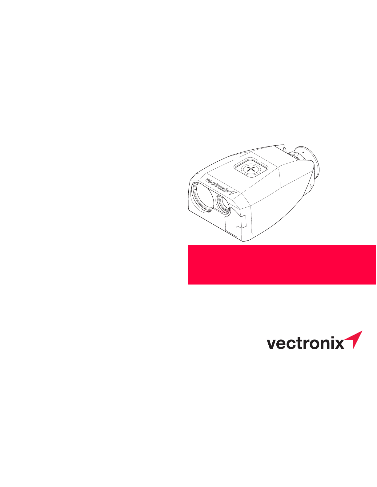
PLRF25C / PLRF25C BTBT
User Manual
English, Version 1.2
II 2013
Pocket Laser Range Finder with
Compass

General Information PLRF25C-1.2en
2
General Information
Short Description PLRF25C / PLRF25C BT
The PLRF25C is a ruggedized, pocket size, handheld, one button operated laser rangefinder with integrated digital magnetic compass, sighting optic and data interface. The
PLRF25C is capable to provide distance, azimuth and inclination information. The
version PLRF25C BT is additonally equipped with integrated Bluetooth functionality.
Meaning of the Symbols
Warning
Indicates a potentially hazardous situation or an unintended use which, if not
avoided, could result in death or serious injury.
Caution
Indicates a potentially hazardous situation or an unintended use which, if not
avoided, may result in minor or moderate injury and/or appreciable material, financial and environmental damage.
Information
Gives reference to an important information for analysis of that important text.
PLRF25C-1.2en General Information
3
For safe use of the device, please note the safety directions included in the
User Manual.
© 2013 Vectronix AG, ® All rights reserved.
Warning
Use of controls or adjustments or performance of procedures other than
those specified herein may result in hazardous laser light exposure. Do not
open the device housing or attempt your own repairs. Do not manipulate
or adjust the performance of the device.
Warning
Not following correct operating procedures or practices could result in
personal injury or loss of life.
Warning
Distance measurements on reflective objects (e.g. traffic signs, number
plates) may cause false readings.

Contents PLRF25C-1.2en
4
Contents
Safety Notices . . . . . . . . . . . . . . . . . . . . . . . . . . . . . . . . . . . . . . . . . . . . . . . . . . . . . . . 7
Care and cleaning . . . . . . . . . . . . . . . . . . . . . . . . . . . . . . . . . . . . . . . . . . . . . . . . . . . 11
Technical Data . . . . . . . . . . . . . . . . . . . . . . . . . . . . . . . . . . . . . . . . . . . . . . . . . . . . . . 13
Getting started . . . . . . . . . . . . . . . . . . . . . . . . . . . . . . . . . . . . . . . . . . . . . . . . . . . . . . 17
Instrument Overview . . . . . . . . . . . . . . . . . . . . . . . . . . . . . . . . . . . . . . . . . . . . . . 17
Changing the battery . . . . . . . . . . . . . . . . . . . . . . . . . . . . . . . . . . . . . . . . . . . . . . 18
Diopter adjustment . . . . . . . . . . . . . . . . . . . . . . . . . . . . . . . . . . . . . . . . . . . . . . . . 19
Reticle . . . . . . . . . . . . . . . . . . . . . . . . . . . . . . . . . . . . . . . . . . . . . . . . . . . . . . . . . 20
General Operations . . . . . . . . . . . . . . . . . . . . . . . . . . . . . . . . . . . . . . . . . . . . . . . 21
Signs And Symbols Measurement Results . . . . . . . . . . . . . . . . . . . . . . . . . . . . . 22
Overview Menu . . . . . . . . . . . . . . . . . . . . . . . . . . . . . . . . . . . . . . . . . . . . . . . . . . . . . . 23
Measurement Functions . . . . . . . . . . . . . . . . . . . . . . . . . . . . . . . . . . . . . . . . . . . . . . 24
Factors affecting measurement range . . . . . . . . . . . . . . . . . . . . . . . . . . . . . . . . . 24
Factors influencing azimuth accuracy . . . . . . . . . . . . . . . . . . . . . . . . . . . . . . . . . 25

PLRF25C-1.2en Contents
5
Complete measurement with data transfer (slope distance,
horizontal and vertical distance, azimuth, inclination) . . . . . . . . . . . . . . . . . . . . .26
Multiple object measurement . . . . . . . . . . . . . . . . . . . . . . . . . . . . . . . . . . . . . . . .27
Distance between two objects . . . . . . . . . . . . . . . . . . . . . . . . . . . . . . . . . . . . . . .28
Distance gate. . . . . . . . . . . . . . . . . . . . . . . . . . . . . . . . . . . . . . . . . . . . . . . . . . . . . . . .29
Compass calibration. . . . . . . . . . . . . . . . . . . . . . . . . . . . . . . . . . . . . . . . . . . . . . . . . .30
General instructions . . . . . . . . . . . . . . . . . . . . . . . . . . . . . . . . . . . . . . . . . . . . . . .30
Calibration instructions . . . . . . . . . . . . . . . . . . . . . . . . . . . . . . . . . . . . . . . . . . . . .31
Perform compass calibration . . . . . . . . . . . . . . . . . . . . . . . . . . . . . . . . . . . . . . . .32
Results . . . . . . . . . . . . . . . . . . . . . . . . . . . . . . . . . . . . . . . . . . . . . . . . . . . . . . . . .33
Declination. . . . . . . . . . . . . . . . . . . . . . . . . . . . . . . . . . . . . . . . . . . . . . . . . . . . . . . . . .34
Declination setting / correction . . . . . . . . . . . . . . . . . . . . . . . . . . . . . . . . . . . . . . .36
Settings . . . . . . . . . . . . . . . . . . . . . . . . . . . . . . . . . . . . . . . . . . . . . . . . . . . . . . . . . . . .37
Settings – Overview . . . . . . . . . . . . . . . . . . . . . . . . . . . . . . . . . . . . . . . . . . . . . . .37
Change Settings . . . . . . . . . . . . . . . . . . . . . . . . . . . . . . . . . . . . . . . . . . . . . . . . . .38

Contents PLRF25C-1.2en
6
Built-In-Test . . . . . . . . . . . . . . . . . . . . . . . . . . . . . . . . . . . . . . . . . . . . . . . . . . . . . . . . 40
Set Default Settings . . . . . . . . . . . . . . . . . . . . . . . . . . . . . . . . . . . . . . . . . . . . . . . . . . 42
Troubleshooting . . . . . . . . . . . . . . . . . . . . . . . . . . . . . . . . . . . . . . . . . . . . . . . . . . . . . 43
Data transfer . . . . . . . . . . . . . . . . . . . . . . . . . . . . . . . . . . . . . . . . . . . . . . . . . . . . . . . . 48
Connecting the interface cable . . . . . . . . . . . . . . . . . . . . . . . . . . . . . . . . . . . . . . 48
Data transfer format to PC, PLGR and DAGR . . . . . . . . . . . . . . . . . . . . . . . . . . . 50
Equipment. . . . . . . . . . . . . . . . . . . . . . . . . . . . . . . . . . . . . . . . . . . . . . . . . . . . . . . . . . 51
Parts List . . . . . . . . . . . . . . . . . . . . . . . . . . . . . . . . . . . . . . . . . . . . . . . . . . . . . . . 51
Accessories . . . . . . . . . . . . . . . . . . . . . . . . . . . . . . . . . . . . . . . . . . . . . . . . . . . . . 52
Options . . . . . . . . . . . . . . . . . . . . . . . . . . . . . . . . . . . . . . . . . . . . . . . . . . . . . . . . . . . . 53
DAGR Settings . . . . . . . . . . . . . . . . . . . . . . . . . . . . . . . . . . . . . . . . . . . . . . . . . . . 55
PLGR+96 / PLGR II Settings . . . . . . . . . . . . . . . . . . . . . . . . . . . . . . . . . . . . . . . 57
Bluetooth Settings. . . . . . . . . . . . . . . . . . . . . . . . . . . . . . . . . . . . . . . . . . . . . . . . 58
Fall of shot - FOS . . . . . . . . . . . . . . . . . . . . . . . . . . . . . . . . . . . . . . . . . . . . . . . . . 60
Customer service . . . . . . . . . . . . . . . . . . . . . . . . . . . . . . . . . . . . . . . . . . . . . . . . . . . . 62
Quality system . . . . . . . . . . . . . . . . . . . . . . . . . . . . . . . . . . . . . . . . . . . . . . . . . . . 63
PLRF25C-1.2en Safety Notices
7
Safety Notices
Laser Safety: Class 1
according to IEC60825-1 Ed 2.0 (2007-03)
The knowledge of this instruction and the
local authorities instructions is the basic for
a save use of the instrument.
Important!
Keep the instructions always in direct
access for user and any personnel working
at the instrument.
Intended purpose
The device
• is designed as a handheld observation
and surveying aid;
• is to be used in addition to other instruments or techniques;
• must never be used as a sole surveying
instrument.

Safety Notices PLRF25C-1.2en
8
Limitations of use
The device must not be used in the vicinity
of sensitive electrical equipment.
All other usage limitations are mentioned in
the technical specifications.
Inappropriate use
• Device deployment without prior knowledge of the operating instructions and
safety notices.
• Changes and modifications to the device
by the customer.
• Use of accessories not expressly
approved by Vectronix AG.
• Working in explosive enviroment or
underground.
• Testing or inspection of device not
named as applications in the intended
use.
• Use of the device without instruction.
• Use outside of the intended limits.
• Opening the device using tools, for
example screwdriver.
• Use after misappropriation.
• Use of device with obviously recognizable damages or defects.
Inappropriate use brings
the risk of
• injuries;
• instrument errors;
• damage to property;
• malfunction;

PLRF25C-1.2en Safety Notices
9
Obligation of the Operator
The person responsible for the product
must ensure that
• the operators are qualified according to
the local authorities directives;
• all users understand these directions and
adhere to them.
Avoiding storage and transport
damage
• When not in use, always keep the device
in its pouch.
• Remove the battery prior to prolonged
storage. Battery leakage can damage the
device.
• Observe the permissible storage temperatures.
• Do not expose the device to strong
mechanical shocks or abrupt temperature transitions during transport (moisture
condensation).
• Use the pouch and transit case or equivalent packaging for shipment.
Avoiding measurement errors
• Note the factors affecting measurement
accuracy (see pages 24, 25).
• Always perform test measurements after
the device has been exposed to rough
handling (vibration, falls,etc.), and before
carrying out important measurement
tasks.

Safety Notices PLRF25C-1.2en
10
Blinding hazard
• Do not look into powerful light sources
with the device.
• Do not open the device. The built-in laser
can cause eye injuries.
Explosion hazard
The battery must not be
• short-circuited;
• recharged;
• mechanically modified;
• placed in fire or exposed lonely or with
the device to temperatures above +85°C
(185°F).
Physical injury hazard
• Do not place the device on a vehicle
parcel-shelf or dashboard – risk of injury
when braking.
Environmental hazard
• The device does not contain extremely
hazard materials. For handling and
disposal of the battery and the
electro-optical device the country specific
regulations have to be respected.
• Deposit used batteries at a proper
collection point.

PLRF25C-1.2en Care and cleaning
11
Care and cleaning
The devices performance
and serviceability are conditional on regular care and
immediate attention to
problems:
• Do not touch glass lenses
with fingers.
• Do not soil the operating
keys with oil or grease.
• Avoid abrupt
temperature transition,
since these can cause
condensation
moisture to develop inside
the device.
The device does not need
special care or cleansers.
Therefore
• do not use any kind of
impregnated cloth
intended for cleaning
spectacle lenses,
• do not use any solvent
except water, e.g. no
alcohol or cleansers.
Lens cleaning
Particles of dirt should be
blown off or removed using
a soft brush.
Finger prints may be
cleaned first by wiping with
a damp cloth, followed by
soft, clean optical tissue or
chamois leather.

Care and cleaning PLRF25C-1.2en
12
Cleaning the casing
Wipe the casing with a
damp cloth. Pay special
attention to dirt and grease
around the button.
Blow out the device
interface cable socket, and
clean it carefully.
Allow the device to dry fully
before packing.
Cleaning the interface
cable
Protect the cable from damp
and dirt as much as
possible! Wipe the cable
with a damp cloth. Blow out
soiled cable plugs with
clean air, and leave them to
dry.

PLRF25C-1.2en Technical Data
13
Technical Data
Optics
Observation monocular
Magnification 6x
Objective diameter 30 mm
Field of view 6° / 106 mil
Focus fixed (50m to infinity)
Dioptric setting +4dpt to -4dpt

Technical Data PLRF25C-1.2en
14
Magnetic Compass (azimuth and inclination)
Azimuth units 360° / 6400mil / 6300mil / 6000mil
Accuracy (1σ)
Azimuth
Inclination angle
± 10mil / ±0.6°
± 3mil / ±0.2°
Display resolution 1° / 1 mil
Max. inclination and bank angle ±45°
Compass calibration menu driven
Declination
Array (adjustable)
Increment
± 179.9°
0.1° / 1 mil

PLRF25C-1.2en Technical Data
15
* at visibility 15km, 2.3 x 2.3m target size, albedo 0.4, detection probability >90%
Rangefinder
Laser type 1550 nm
Eye safety Class 1
Standard IEC60825-1 Ed 2.0 (2007-03)
Range Performance 5m to >4000m
Specified Performance 2500m*
Accuracy (1σ) ±2 m (>50m to <1500m)
±5 m (<50m / >1500m)
Display Resolution 1m / 1ft / 1yd

Technical Data PLRF25C-1.2en
16
Miscellaneous
Power supply 1x 3V lithium battery, type CR123A
Battery capacity (20°C) > 3000 measurements
Immersion
standard
optional
1m, 30min
10m, 30min
Operational temperature range -35°C to +63°C / -31°F to +145°F
Storage temperature range (without battery) -40°C to +85°C / -40°F to +185°F
Weight with battery and rubber cover 500g / 1.1lbs
Dimensions with rubber cover
length
width
height
131mm / 5.2in
88mm / 3.5in
56mm / 2.2in
Tripod interface 1/4 inch thread
Data interface:
PLRF25C / PLRF25C BT
PLRF25C BT
RS232
Bluetooth (Serial Port Profile)
PLRF25C-1.2en Getting started
17
Getting started
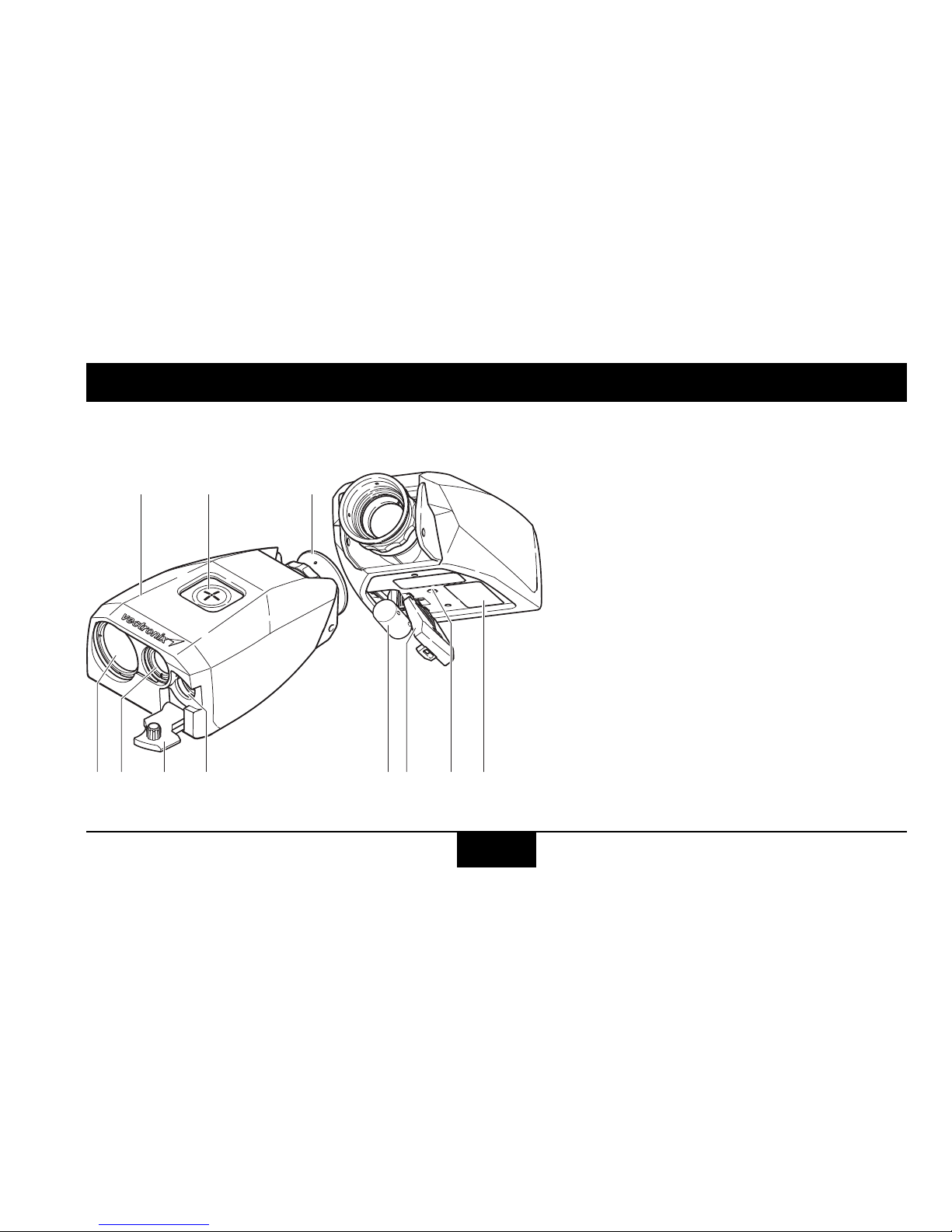
Instrument Overview
a) Rubber Cover
b) Push Button
c) Eyecup
d) Objective – Day Optics
e) Objective – Transmitter
f) Interface Protection Cap
g) Interface Connector
(5-Pin LEMO)
h) Battery, CR123A
i) Battery Case Cover
j) Tripod Mount
(1/4 inch)
k) Type label (Name, Part
Number, Serial Number)
a
de f h jikg
bc
Getting started PLRF25C-1.2en
18
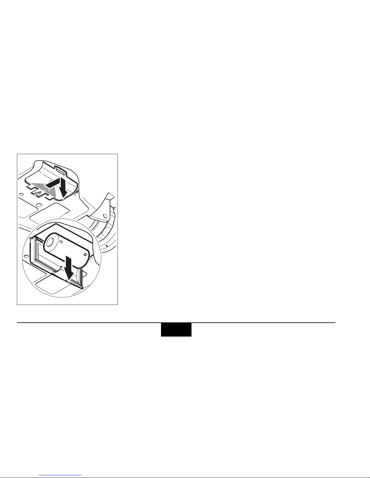
Changing the battery
Open the battery compartment.
Insert one lithium battery type CR123 with +(positive) pole
facing to the objectives.
Close the battery cover.
The device monitors the condition of the batteries. If the
display shows
BATT LOW, this indicates that the battery is
almost used up. You can still get readings, but the battery
needs to be replaced at the next occasion.
The message
BATT LOW may also appear under cold
conditions, since low temperature reduces the
performance of the batteries.
Remove the battery before storing.
PLRF25C-1.2en Getting started
19
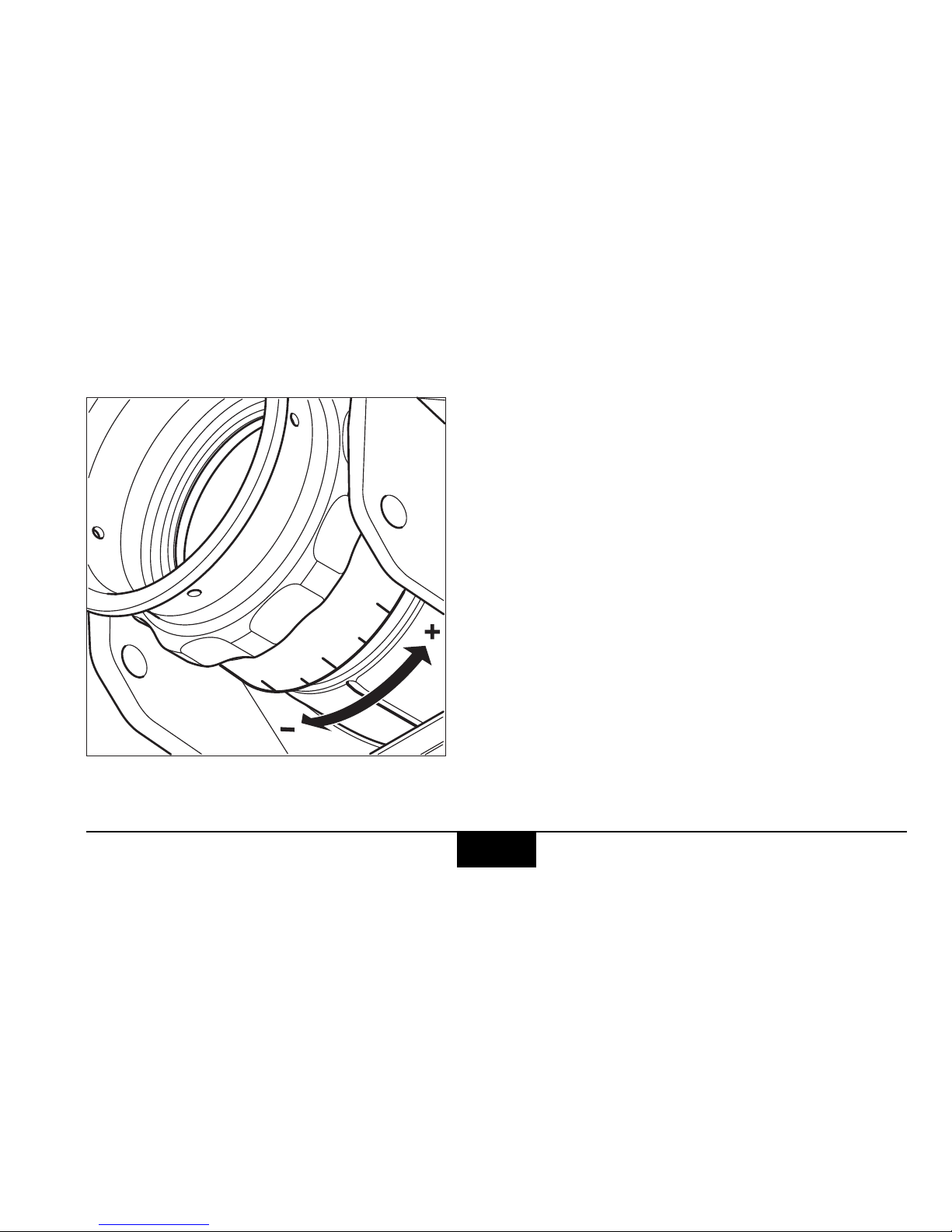
Diopter adjustment
Focus on an object farther than 100 m
away and rotate the eyepiece to obtain a
sharp image.
Standard setting: 0 diopter
If the device is being used by different
people, remember your personal
diopter setting.
0
-
+
2
2
Getting started PLRF25C-1.2en
20
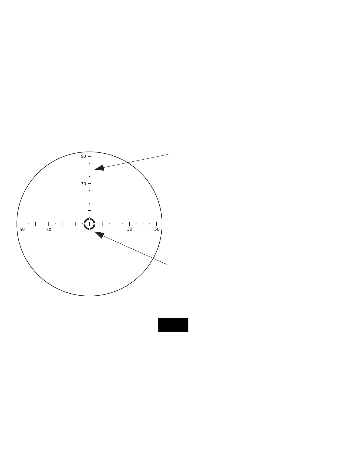
Reticle
Glass reticle
The device is equipped with an engraved
glass reticle.
Line to line spacing: 10 mil
Line to point spacing: 5 mil
1 mil corresponds to 1 m spacing at a
distance of 1 km.
Electronic reticle
An illuminated aiming mark can be activated for the use under poor lighting conditions.

PLRF25C-1.2en Getting started
21
General Operations
The device is operated
entirely by one push button
only.
You can prolong the
display period by
holding down the
button while the result
is displayed.
The button operation is indicated by the following
symbols:
press down the button
and keep it pressed
release the button
press and release the
button quickly (click)
number of clicks
(e.g. 3 clicks)
press and hold down
the button for the indicated time
(e.g. >2 seconds)
Hold the device steady
during measurement.
The device displays the
measurement result, then
switches itself off automatically after a few seconds.
3x
>2s
3x
>2s

Getting started PLRF25C-1.2en
22
Signs And Symbols Measurement Results
Complete Measurement Distance Between Two
Objectes
Abreviations Units
D
Distance (air-line)
H
Horizontal Distance
V
Vertical Distance
AZI
Azimuth
INC
Inclination Angle
D 1245çD 1245ç
H 1240çH 1240ç
V 108çV 108ç
AZI 215°AZI 215°
INC 5°INC 5°
AZIAZI
INCINC
H
D
V
D
Distance (air-line)
D 1200çD 1200ç
D
ç
Meter
F
Feet
:
Yard
&
Mil
°
Degree
D 2475çD 2475ç
D 5844FD 5844F
D 1980:D 1980:
AZI 5624&AZI 5624&
AZI 135°AZI 135°

PLRF25C-1.2en Overview Menu
23
Overview Menu
Complete Measurement with data transfer 1x
Distance between two points and Fall of Shot (optional) 2x
Distance Gate 3x
Compass Calibration 4x
Declination 5x
Settings (Configuration, Units & Interface) 6x
Built-In-Test 7x
Default Settings 8x

Measurement Functions PLRF25C-1.2en
24
Measurement Functions
Factors affecting measurement range
Reflective properties
Size of the target
Oblique surfaces
Atmospheric conditions Vibration Lighting conditions

PLRF25C-1.2en Measurement Functions
25
Factors influencing azimuth accuracy
The device has a digital compass that works similar to a magnetic compass. Metal
objects, magnetic fields and electronic devices (e.g. radio) can cause error in directional
readings. Nonmagnetic metals and alloys do not affect the compass readings.
Countermeasures
• A compass calibration must be performed after every battery change
(see page 30)
• Observe the minimum safe distances shown above when making azimuth
measurements or compass calibration.

Measurement Functions PLRF25C-1.2en
26
Complete measurement with data transfer (slope distance,
horizontal and vertical distance, azimuth, inclination)
Press and hold the button.
The azimuth appears and
is updated continuously.
Sight the object with the
aiming mark.
Hold the device steady as
you release the button.
The slope distance
D is
displayed.
If no distance could be
detected,
D---- appears.
While the display is on, click
the button to get the
horiziontal distance
H. Repeat
the step above to obtain the
vertical distance
V, the
azimuth
AZI and the inclina-
tion angle
INC.
The measurement data (distance, azimuth and inclination) is transmitted to the
interface just after a measurement is taken.
AZI 325°AZI 325°
D 1245çD 1245ç
H 1240çH 1240ç
V 108çV 108ç
AZI 215°AZI 215°
INC -5°INC -5°

PLRF25C-1.2en Measurement Functions
27
Multiple object measurement
Up to three distances in the
line of sight can be obtained
with a single measurement.
To use this feature the
function
3DIS ON must be
activated (see page 37).
Perform a measurement as
described before. If more
than one distance has been
detected, it is indicated with
a number (1, 2 or 3) at the
very left.
While the display is on, click
the button repeatedly to
display all the obtained
measurement values.The
order of the shown ranges
is: strongest, 2nd strongest
and 3rd strongest detected
signal.
Always the distance with the strongest signal will be transmitted to the
interface.
589ç
589ç
1245ç
1245ç
1D 589ç1D 589ç
1H 587ç1H 587ç
1V 51ç1V 51ç
2D 1245ç2D 1245ç
2H 1240ç2H 1240ç
2V 109ç2V 109ç
AZI 215°AZI 215°
INC -5°INC -5°

Measurement Functions PLRF25C-1.2en
28
Distance between two objects
Click the button one time
then immediately press and
hold it down. The azimuth
appears and is updated
continuously. Sight the first
object with the aiming mark.
Release the button to
measure the first point.
PT1 OK followed by
DO PT2 is displayed.
Immediately press and hold
down the button again.
Sight the second point.
Release the button to
measure the second point.
The distance
D between the
two points is displayed.
AZI 325°AZI 325°
PT1 OKPT1 OK
DO PT2DO PT2
1200 m
D 1200çD 1200ç

PLRF25C-1.2en Distance gate
29
Distance gate
In certain cases, it may be
useful to limit the closest
distance the device will
measure. Click the button
three times in rapid
succession.
DIS-GATE appears briefly
followed by the current
setting.
Click the button to scroll
through the available
values.
D GATED is displayed
when a distance within
the set distance gate is
measured.
To store the desired setting,
press and hold down the
button for >2 seconds. The
setting is not changed if
CANCEL is displayed.
3x
DIS-GATEDIS-GATE
SET OFFSET OFF
OFF
200m
300m
400m
SET OFFSET OFF
200ç 200ç
300ç 300ç
400ç 400ç
SET 300çSET 300ç
-STORED--STORED-
300ç300ç
-STORED--STORED-
>2s

Compass calibration PLRF25C-1.2en
30
Compass calibration
General instructions
How?
There is a choice of two calibration procedures
• 12 point calibration
(recommended)
provides best precision.
• 4 point calibration
May achieve adequate
precision for many
applications if time does
not permit a 12 point
calibration.
When?
• After every battery
change
• After the device has been
exposed to strong
magnetic fields.
• After parts have been
attached or removed to
the device (e.g. night
vision device)
Check the stored declination after every compass calibration and
correct if necessary.
Where?
In a open area (e.g. a field)
at an adequate distance
from buildings and metallic
objects (see page 25).
Ensure that there are no
buried pipes, cables, etc. in
the vicinity.
Never calibrate the
compass inside a
building or in the
vicinity of disruptive
magnetic fields.

PLRF25C-1.2en Compass calibration
31
Calibration instructions
The device needs to be
moved in various directions
during calibration. Instructions for the movements
appear successively in the
display:
Important:
When the
HOLD POS
instruction is displayed,
immediately hold the device
still and wait for the next
instruction. Perform each
movement slowly and
steadily, until the next
instruction is displayed.
UP:
DOWN:
turn up
turn down
ROT 90°: rotate 90°
+30°
-30°
UPUP
DOWNDOWN
TLT RIGH: Tilt the right
side of the device down.
HOLD POS: Hold the device
steady at the current
position
TLT LEFT: Return to hori-
zontal.
Always turn in the same
direction for all
ROT 90°instructions.
ROT 90°
ROT 90°
TLT LEFTTLT LEFT
TLT RIGHTLT RIGH
-30°

Compass calibration PLRF25C-1.2en
32
Perform compass calibration
Click the button four times in
rapid succession.
DMC CAL appears briefly
followed by the first available calibration procedure.
Click the button to scroll
through the available
calibration procedures.
Press and hold down the
button for >2 seconds to
start the displayed
procedure.
Follow the instructions in
the display.
4x
DMC CALDMC CAL
4PT CAL4PT CAL
4PT CAL4PT CAL
12PT CAL 12PT CAL
>2s
UPUP
HOLD POSHOLD POS
......

PLRF25C-1.2en Compass calibration
33
Results
The calibration result is
displayed at the end of the
procedure.
GOOD indicates a
successful calibration.
If the result is
BAD, perform
a 12 point calibration until a
GOOD is obtained. Consider
to move to an alternative
location.
Magnetic interferences can
still lead to inaccurate
measurements, even if the
calibration was successful.
For this reason the
compass accuracy should
be verified after a
successful calibration by
performing several azimuth
measurements on known
landmarks and compare the
results.
Possible causes of calibration failures:
• the device was moved
while
HOLD POS was
displayed.
• movements were
performed to fast or
jerkily.
• the location is to close to
magnetic disturber.

Declination PLRF25C-1.2en
34
Declination
Declination explanation
• Within the context of using PLRF25C,
declination is understood as the deviation
between magnetic north (MN) and grid
north (GiN).
• Anyway, depending on the country or
region declination possibly can be understood as deviation between magnetic
north (MN) and geographical north
(GgN).
To get the correct azimuth from PLRF25C
in a certain coordinate system:
1. The deviation between magnetic north
(MN) and grid north (GiN) of the specified coordinate system must be known.
2. This deviation must be set in the
DECLNATN menu (see page 36).
• Declination D:
Angle between GgN and MN
• Declination d:
Angle between GiN and MN
• Meridian convergence c:
Angle between GiN and GgN
GiN
-D
-c
-d
GgN
GgN
GiN=GgN
MNMNMN
-D
-d
GiN
-D
+c
-d

PLRF25C-1.2en Declination
35
When working with geographical coordinates GgN = GiN and
therefore the declination D = d.
Declination d is negative when MN lies
west (left) of GiN and is positive when
MN lies east (right) of GiN.
The declination is displayed in the
currently selected angular unit
(see page 37)
The stored declination value:
• is retained when the measurement units
are changed.
• is retained when the battery is exhausted
or replaced.
• is factory set to zero (0).

Declination PLRF25C-1.2en
36
Declination setting / correction
Click the button five times in
rapid succession.
DECLNATN appears briefly
followed by currently set
declination value.
The first digit is blinking.
Set digit by digit from left to
right. Click to change the
value of the blinking digit.
Press and hold for more
than two seconds to store
the current digit.
Storing the very last digit
stores the complete set
value. The setting is not
changed if
CANCEL is
displayed.
5x
DECLNATNDECLNATN
DL +000_0°DL +000_0°
DL -005_5°DL -005_5°
>2s
>2s
-STORED--STORED-
-005_5°-005_5°
-STORED--STORED-

PLRF25C-1.2en Settings
37
Settings
Settings – Overview
Configuration (CONFIG)Units (UNITS) Interface (INTRFACE)
In sub-menu
CONFIG, the
following functions can be
activated and deactivated:
• Measuring 3 distances
• Electronic reticle
• Night Vision Mode.
In the sub-menu
UNITS, the
following units can be
selected:
Distance: Meter, Yard, Feet,
Angle: 360°, 6000mil,
6300mil, 6400mil
In the sub-menu
INTRFACE, the available
interface settings can be
set. The choice depends on
the model and on the
options installed.
The selected setting is marked with the star symbol (*).
3DIS ON3DIS ON
3DIS OF*3DIS OF*
ERET ONERET ON
ERET OF*ERET OF*
NVIS ONNVIS ON
NVIS OF*NVIS OF*
METER*METER*
YARDYARD
FEETFEET
360°*360°*
6000MIL6000MIL
6300MIL6300MIL
6400MIL6400MIL
PC*PC*
DAGRDAGR
PLGRPLGR
BTBT

Settings PLRF25C-1.2en
38
Change Settings
In the menu SETTINGS
there are three sub-menus:
CONFIG, UNITS and
INTRFACE.
Click the button 6 times in
rapid succession.
SETTINGS appears briefly
followed by the first submenu
CONFIG.
Click the button to scroll
through the available
submenus.
Press and hold down the
button for >2 seconds to
enter the desired sub-menu.
Click the button to scroll
through the available
settings.
To store the desired setting,
press and hold down the
button for >2 seconds. The
setting is not changed if
CANCEL is displayed at the
end.
6x
SETTINGSSETTINGS
CONFIGCONFIG
>2s
CONFIGCONFIG
UNITUNIT
INTRFACEINTRFACE
>2s
UNITUNIT
METER* METER*
YARD YARD
FEET FEET
......

PLRF25C-1.2en Settings
39
Measuring 3 distances
Function:
3DIS ON / 3DIS OF
3DIS ON allows to obtain
up to three distances in the
line of sight with a single
measurement
(see page 27).
Electronic reticle
Function:
ERET ON / ERET OF
ERET ON activates the
electronic aiming mark
which is useful for poor
lightning conditions.
Night vision mode
Function:
NVIS ON / NVIS OF
NVIS ON reduces the
display brightness. This is
needed in combination with
an attached night vision
device.
10ç10ç
90ç90ç
80ç80ç
Engraved
Reticle
Electronic reticle

Built-In-Test PLRF25C-1.2en
40
Built-In-Test
Click the button seven times
in rapid succession.
B-I-T
appears briefly, the
Built-In-Test starts automatically.
Passed is indicated with
!,
failed with
X. In this case,
please contact the customer
support.
7x
B-I-TB-I-T

PLRF25C-1.2en Built-In-Test
41
Click the button to scroll
through the various items.
Press and hold down to
show all information of an
item.
1. Model: e.g.
PLRF25C
2. Software Version:
e.g.
SW 01_12_00
3. Enabled Options:
e.g.
FOS-DAGR-PLGR
4. Memory Test:
Passed
! or Failed X
5. Display Test:
6. System Test: Passed
!
or Failed
X
7. Battery Level:
OK = Good / BAD = Bad
8. Measuring Counter:
Number of range measurements (e.g.
127)
9. Temperature:
Temperature inside the
device in degree Celsius
(e.g.
+28°C)
B-I-T!B-I-T!
PLRF 25CPLRF 25C
00_09_1100_09_11
OPTIONSOPTIONS
MEMORYMEMORY
DISPLYDISPLY
SYSTEM!SYSTEM!
BATT LVLBATT LVL
MEAS CNTMEAS CNT
TEMPTEMP
%%%%%%%%;%%%%%%%%;

Set Default Settings PLRF25C-1.2en
42
Set Default Settings
Click the button eight times
in rapid succession.
SET-DEF appears in the
display followed by
NO.
Click again until
YES is
shown.
Press and hold down the
button for >2 seconds to
store the default settings.
The default settings are not
stored if
CANCEL is
displayed.
The default settings for the
standard model are:
Electronic aiming
mark:
ERET OF
Distance Gate: OFF
Declination: + 000_0°
Night Mode: NVIS OF
Multiple Object
Measurement:
3DIS OF
Distance Unit: METER
Angular Unit: 360°
Interface Setting: PC
For customized
versions, the default
settings might be
different.
8x
SET-DEFSET-DEF
NONO
YESYES
>2s
-STORED--STORED-
DEFAULTSDEFAULTS
-STORED--STORED-

PLRF25C-1.2en Troubleshooting
43
Troubleshooting
Problem Possible cause Solution
Measurements can
not be taken - no
function at all
The battery has run out Replace battery
(see page 18)
Battery contacts corroded Clean battery contacts
Low temperature reduces
performance of battery
Warm up battery
Extreme heat shortens batteries
life
Do not store the battery at
temperature over +70°C
The device is defective Contact the customer
support

Troubleshooting PLRF25C-1.2en
44
D---- is displayed
after distance measurement
Distance is outside the
specified range
Respect specified
measurement range
(see page 15)
Object too small or inaccurately
targeted
Respect factors affecting
measurement range
(see page 24)
Bad weather conditions
AZI---- is
displayed.
Tilt angle outside specified range Respect specified tilt angles
Digital magnetic compass
damaged
Contact customer support
INC---- is
displayed.
Tilt angle outside specified range Respect specified tilt angles
Tilt sensors are damaged Contact customer support
Problem Possible cause Solution

PLRF25C-1.2en Troubleshooting
45
D GATED is displayed
after distance measurement
Measured distance is below
selected distance gate
Reduce or turn off the
distance gate (see page 29)
The following
symbols are
displayed during
azimuth measurements:
_
_ _
_
_
_ _
_
_
_ _
_
_
_ _
_
The allowed inclination and / or tilt
angle has been exceeded
tilted too far upwards
tilted too far downwards
tilted too far to the right
tilted too far the left
Stay within specified inclination and / or tilt angle
(see page 14)
Problem Possible cause Solution

Troubleshooting PLRF25C-1.2en
46
Inaccurate azimuth
values
Incorrect declination setting
Disruptive magnetic fields at
measuring position
Bad calibration
Altered magnetic conditions
within the instrument
(e.g. battery change)
Set correct declination (see
page 36)
Respect factors affecting
azimuth measurement
accuracy (see page 25)
Perform compass
calibration (see page 30)
Perform compass
calibration (see page 30)
Compass calibration
can not be completed
Timing out of calibration Follow the instructions
slightly faster (see page 31)
Problem Possible cause Solution

PLRF25C-1.2en Troubleshooting
47
The electronic reticle
is not visible
ERET OF is set in the
configuration menu
Select ERET ON in the
configuration menu
(see page 37)
BATT LOW is
displayed
The battery is almost used up Replace battery
(see page 18)
The device measures
objects in front or
behind the intended
object
3DIS OF is set in the
configuration menu, only the
distance with the highest return
signal is displayed
Select
3DIS ON in the
configuration menu
(see page 37)
NVIS ON is displayed
after a measurement
The device is used during daylight
conditions with
NVIS ON selected
in the configuration menu
Select
NVIS OF in the
configuration menu
(see page 37)
Problem Possible cause Solution

Data transfer PLRF25C-1.2en
48
Data transfer
Connecting the interface cable
On the front side of the
device is a socket for
sending data to:
• personal computers or
laptops
• modems
• fire control systems
• C4I systems
Our customer service
will be pleased to
inform you in details
about the different
possibilities.
Caution:
Incorrect handling can
damage the socket or
optional interface cable.

PLRF25C-1.2en Data transfer
49
To plug:
1. Remove protection cap.
2. Align the respective
markings on the plug and
socket.
3. Slide the plug carefully
into the socket until the
locking mechanism
engages.
To unplug:
1. Grasp the plug grip
between two fingers,
2. draw it carefully back to
the stop to disengage the
locking mechanism,
3. pull back a little harder
until the plug slips out of
the socket.
4. Attach the protection
cap.

Data transfer PLRF25C-1.2en
50
Data transfer format to PC, PLGR and DAGR
Interface parameters
Interface . . . . . . . . . . . .RS-232
Data
transmission . . . . . bidirectional
Baud rate . . . . . . . . . 9600 bps
Parity . . . . . . . . . . . . . . . .none
Data bits . . . . . . . . . . . . . . . . .8
Stop bits . . . . . . . . . . . . . . . . .1
Handshake . . . . . . . . . . . .none
PC
PLGR
DAGR
5 pin connector

PLRF25C-1.2en Equipment
51
Equipment
Parts List
1
2
3
4
5
6
79
8
Standard extent of delivery:
1 PLRF25C / PLRF25C BT 4 909 492 Pouch, black
2 Rubber cover (1x) 5 User Manual
909 394 Rubber cover, black 6 909 493 Short Instruction
910 389 Rubber cover, green 7 906 430 Micro fibre lens cloth
910 390 Rubber cover, desert tan 8 909 486 Neck Strap
3 667 002 3V Li-Battery, CR123A (1x) 9 909 211 Eyecup (Spare Part)

Equipment PLRF25C-1.2en
52
Accessories
Optional:
1 706 271 SEV48 data cable to PC
2 721 951 SEV63 data cable to PLGR and DAGR
for additional accessories (tripods, data cables, transport case, ...) contact the
customer support.

PLRF25C-1.2en Options
53
Options
Overview Interface Options
PC Setting for communication with PC. Data transfer via PC cable. Interface
parameters (RS-232) see page 50.
PLGR Setting for communication with Rockwell Collins GPS PLGR+96 /
PLGR II. Data transfer via PLGR / DAGR cable.
DAGR Setting for communication with Rockwell Collins GPS DAGR. Data
transfer via PLGR / DAGR cable.
BT Setting for wireless Bluetooth communication. Allows data transfer via
Buetooth and PC cable. The data format is the same as for the setting
"PC" (only available on models with integrated Bluetooth function,
PLRF25C BT).

Options PLRF25C-1.2en
54
Use the function Complete Measurement with data transfer to transmit
measurement data (see page 26).
The PLRF is only an enhancement to basic fire support skills. Once a
complete measurement is transfered and received, the user must verify
the target location on a map and verify the measurements.

PLRF25C-1.2en Options
55
DAGR Settings
Setting the PLRF25C
• Store the interface setting
DAGR,
see page 37-38.
Connect the interface cable to
the DAGR J2 connector.
DAGR Setup:
1. MAIN MENU/System/Select function set
• FUNCTION SET: Advanced
2. MAIN MENU/Receiver Setup/Power
Saver
• AUTO-OFF MODE/TIMER: Off
• AUTO-STANDBY MODE: Off
3. MAIN MENU/Receiver Setup/GPS
Setup
• OPERATING MODE: Continuous
• POWER ON OPERATING MODE:
Continuous
• FREQUENCY: L1 Primary
• SV CODE: All-Y
• ELEVATION HOLD: Auto
4. MAIN MENU/Communications/COM
Port Setup
• CONFIGURATION: Standard
• LASER RANGE FINDER (LRF)
TYPE: Other
• COM Port: COM Port 1
5. MAIN MENU/Display Setup/UNITS
• MAGVAR TYPE: Calculated - WMM
Azimuth in PLRF25C and
azimuth on DAGR may be
different due to declination
setting.

Options PLRF25C-1.2en
56
• DAGR Targeting Operations:
1. Conduct a combined measurement with
data transfer, see page 26.
2. Upon receipt of LRF SHOT RECEIVED
dialog, review/evaluate Azimuth, Range,
and Elevation Angle. The DAGR will
allow the operator to show a total of
three shots at one time. Once the operator determines that he has a good
targeting solution he will highlight the
desired shot and: Press ENTER to
continue to FIRE SUPPORT pages or
Press QUIT to discard shot without
creating a waypoint.
3. Check all data in the SAFETY CHECKS
fields and ensure that no fields on the
Fire Support Pages are blinking
between grey and black text (indicates
that calculation is based on invalid fix).
4. To store the target location as a LRF
Waypoint, highlight the STORED AS
WP field, then push the ENTER key.
DAGR highlights the first available
unused waypoint or highlight the desired
waypoint, then push the ENTER key.
Edit Name, Remark, or Identity Type of
waypoint if required.

PLRF25C-1.2en Options
57
PLGR+96 / PLGR II Settings
Setting the PLRF25C
• Store the Interface setting
PLGR,
see page 37-38.
Setting the PLGR+96 / PLGR II
• Set the tracking mode to CONT.
• Select the position format which corresponds to the map being used.
• Select the appropriate ELEV units.
• Select the appropriate ELEV reference.
• Select the appropriate ANG units.
• Select the ANG reference (Grid).
• Select the datum which corresponds to the
map being employed.
The proper datum must be selected.
Improper datum selection will result
in poor target position accuracy.
• Set the AUTOMATIC OFF TIMER to OFF.
• Set the SERIAL mode to standard.
Additional setting for PLGR II
• Configure port C to IP.
• Configure the remaining ports to IP (or
RTCM-NMEA).
• Set the port C baud rate at 9600-9600.
• Change the LRF mode to TARGETING.
Azimuth in PLRF25C and azimuth
on PLGR+96 / PLGR II may be
different due to declination
setting.

Options PLRF25C-1.2en
58
Bluetooth Settings
Setting the PLRF25C BT
• Store the interface setting
BT,
see page 37-38
•
PAIRING appears in the field of view. The
Bluetooth module is turned on and allows
the pairing with a Bluetooth receiver
device. The pairing mode may be
terminated manually by pressing the
button or automatically after approx.
100sec.
CANCEL is displayed for a short
instant.
Messages
BT FAIL: Bluetooth data transfer failed
CANCEL: The Bluetooth module is shut
down.
PAIRING: The Bluetooth module is turned
on and ready for pairing with a Bluetooth
receiver device
SUCCESS: The pairing process was
completed successfully
The PLRF25C BT pairing PIN code is
zero (0). The PLRF25C BT supports
the Bluetooth SPP (serial port profile)
service.

PLRF25C-1.2en Options
59
When not using Bluetooth it is
recommended to permanently
disable the Bluetooth
communication by choosing the
interface setting
PC.
Transmission range depends on
various influences. Best results are
achieved with a "free line of sight"
between PLRF25C BT and receiver
device. Avoid shielding (e.g. hands
around Bluetooth antenna or
aluminum hard case for receiver
device).
The integrated Bluetooth module complies
with Part15 of the FCC Rules. Operation is
subject to the following two conditions: (1)
it may not cause harmful interferences, and
(2) it must accept any interferences
received, including interferences that may
cause undesired operation.

Options PLRF25C-1.2en
60
Fall of shot - FOS
Click the button once, then
immediately press and hold
it down.
The azimuth appears and is
updated continuously. Sight
the target with the aiming
mark.
Release the button to
measure the target.
PT1 OK followed by
DO PT2 is displayed.
Immediately press and hold
down the button again.
Sight the fall of shot.
Release the button to
measure the fall of shot.
The distance (
D) between
the target and fall of shot is
displayed.
AZI 504&AZI 504&
PT1 OKPT1 OK
DO PT2 DO PT2
D 20çD 20ç
20m

PLRF25C-1.2en Options
61
Fall of shot - FOS (continued)
While the display is on, click
the button repeatedly to
display the FOS correction
values.
Click button repetitive to
obtain the corrections
again.
Example:
Is a shot left, short and to
low, the corrections given
are:
RT for right, AD for add
and
UP for up.
RT13çRT13ç
AD 1çAD 1ç
1m
13m
3m
AD
RT
RT 13M
AD 1M
UP 3M
Right (RTRT)
Left (
LTLT)
Add (
ADAD)
Drop (
DPDP)
Down
(
DNDN)
Up (
UPUP)

Customer service PLRF25C-1.2en
62
Customer service
Our customer and information service will
be glad to offer assistance if your instrument requires maintenance, if it sustains
damage, or if you require any other information:
Vectronix AG
Max-Schmidheiny-Strasse
CH-9435 Heerbrugg
(Switzerland)
Telephone: +41 71 726 72 00
Fax: +41 71 726 72 01
Internet: www.vectronix.ch
Copyright
Without the prior written permission of
Vectronix this document may neither be
copied in part or whole by mechanical,
photographic, electronic or any other
means (this includes converting it to any
machine-readable form), nor be stored in
an information storage system, nor be used
for any purpose other than that intended,
nor be made available or passed on to any
third party who has not been expressly
authorised by Vectronix.

PLRF25C-1.2en Customer service
63
Quality system
For over 10 years, Vectronix AG has an
Integrated Management System (IMS) in
place.
The IMS is certified by the Swiss Association for Quality and Management Systems
(SQS) to meet the international standards
for quality management systems to ISO
9001 and Environmental management
systems to ISO 14001.
With our quality policy, "We set the
standards and are responsible for
delivering excellent quality throughout our
work processes", we are always looking for
greater benefits for our customers.

DOC Code: 909496-1.2en
Printed in Switzerland
Copyright by Vectronix AG,
Heerbrugg, Switzerland, II 2013
Vectronix AG
CH-9435 Heerbrugg
(Switzerland)
Telephone +41 71 726 72 00
Fax +41 71 726 72 01
www.vectronix.ch
 Loading...