


VERTEX Plus Collar
User Manual
Version: 1.3
Last Change: 19.03.2019

VERTEX Plus Collar
User Manual
© 2017 VECTRONIC Aerospace GmbH
All rights reserved. No parts of this work may be reproduced in any form or by any means - graphic, electronic, or
mechanical, including photocopying, recording, taping, or information storage and retrieval systems - without the
written permission of the publisher.
Products that are referred to in this document may be either trademarks and/or registered trademarks of the
respective owners. The publisher and the author make no claim to these trademarks.
While every precaution has been taken in the preparation of this document, the publisher and the author assume no
responsibility for errors or omissions, or for damages resulting from the use of information contained in this
document or from the use of programs and source code that may accompany it. In no event shall the publisher and
the author be liable for any loss of profit or any other commercial damage caused or alleged to have been caused
directly or indirectly by this document.
Marcel Butz
Marcel Butz
Ulrike Herrmann
Ulrike Herrmann
04.11.2015
04.11.2015
16.02.2016
22.02.2016
Ulrike Herrmann 22.02.2016

Document Change Record

Table of Contents
4Contents
1 Product overview
2 Fast guide to deploy the collar
3 The VERTEX Plus Collar
GPS Receiver
VHF Beacon
Communication options
Internal Sensors
...................................................................................................................... 113.1
...................................................................................................................... 123.2
...................................................................................................................... 133.3
...................................................................................................................... 173.4
...............................................................................................................8
...............................................................................................................9
...............................................................................................................10
...................................................................................................... 13Iridium Communication 3.3.1
...................................................................................................... 14Globalstar Communication 3.3.2
...................................................................................................... 15GSM Communication 3.3.3
...................................................................................................... 17Mortality & Hibernation Sensor 3.4.1
...................................................................................................... 18Temperature Sensor 3.4.2
...................................................................................................... 18Activity Sensor (Acceleration) 3.4.3
...................................................................................................... 19Proximity and Separation Sensor 3.4.4
UHF Radio Communication
Virtual Fence
Drop Off
External Sensors
...................................................................................................................... 223.5
...................................................................................................................... 223.6
...................................................................................................... 26Virtual Fence in GPS Plus X 3.6.1
Virtual Fence in Google Earth3.6.1.1
........................................................................................................... 28
...................................................................................................................... 303.7
...................................................................................................................... 313.8
...................................................................................................... 31UHF ID Tags 3.8.1

5Contents
...................................................................................................... 32Expandable Fawn Collars 3.8.2
...................................................................................................... 32Vaginal Implant Transmitter (VIT) 3.8.3
...................................................................................................... 33Mortality Implant Transmitter (MIT) 3.8.4
4 Data formats
5 System Set-up
User-Software Installation
Collar Registration
USB to VERTEX Plus Interface Cable
Test the Collar
6 Collar Main Tree
Information
...............................................................................................................34
...............................................................................................................37
...................................................................................................................... 375.1
...................................................................................................................... 375.2
...................................................................................................................... 395.3
...................................................................................................................... 405.4
...............................................................................................................40
...................................................................................................................... 416.1
...................................................................................................... 42Telemetry 6.1.1
...................................................................................................... 46GPS Monitor 6.1.2
...................................................................................................... 47Info File 6.1.3
Configuration
Schedules
...................................................................................................................... 486.2
...................................................................................................................... 616.3
...................................................................................................... 49User Configuration 6.2.1
...................................................................................................... 54Time 6.2.2
...................................................................................................... 55Virtual Fence Polygons 6.2.3
...................................................................................................... 58Start Bootloader 6.2.4
...................................................................................................... 65GPS & Beacon Files Upload 6.3.1
...................................................................................................... 65GPS Schedule 6.3.2
...................................................................................................... 68Beacon Schedule 6.3.3

6Contents
...................................................................................................... 69Communication Schedule 6.3.4
...................................................................................................... 69External Sensor Receiver Schedule 6.3.5
...................................................................................................... 69Proximity GPS Schedule 6.3.6
...................................................................................................... 70Virtual Fence Schedule 6.3.7
Collected Data
7 Remote Collar (Communication)
Remote User Configuration
Remote GPS Schedule
Remote Beacon Schedule
Remote Proximity Schedule
Remote Communication Schedule
Remote Virtual Fences
8 Calculate Collar Lifetime
9 Battery options
10 Changing of battery pack
...................................................................................................................... 706.4
...............................................................................................................71
...................................................................................................................... 727.1
...................................................................................................................... 757.2
...................................................................................................................... 757.3
...................................................................................................................... 767.4
...................................................................................................................... 767.5
...................................................................................................................... 767.6
...............................................................................................................77
...............................................................................................................79
...............................................................................................................80
Oval Collar
Round Collar, standard battery pack
Round Collar, curved battery pack
11 Collar Deployment
12 Specification
Environmental specification for the collar
Declarations of Conformity
Certificates
...................................................................................................................... 8010.1
...................................................................................................................... 8110.2
...................................................................................................................... 8210.3
...............................................................................................................85
...............................................................................................................86
...................................................................................................................... 8612.1
...................................................................................................................... 8712.2
...................................................................................................................... 9012.3

7Contents

1 Product overview
The VERTEX Plus Collar is a modular system that is customized to your project needs.
Your Collar is built with a combination of following options.
Remote Communication Options
- Iridium bi-directional Satellite Communication
- Globalstar Uplink Satellite Communication
- GSM bi-directional Communication
- UHF Radio Communication
- VHF Beacon transmitter (signal transmitter only)
Internal Sensor Options
- Mortality & Hibernation Sensor
Product overview 8
- Temperature Sensor
- Basic Activity Sensor (3-axis acceleration, averaged data each 300sec.)
- Advanced Activity Sensor (High Resolution 3-axis acceleration, raw data up to 32Hz)
The VERTEX Plus Collar with UHF communication is able to communicate with UHF ID
Tags / various external sensors:
External Sensors (Proximity and Separation Application)
- Customizable UHF ID Tags for species interaction
- Expandable fawn collars for offspring survival studies
- Stationary UHF ID Tags for e.g. road crossings, waterholes
- Vaginal Implant Transmitter (VIT) for pregnancy observation
- Mortality Implant Transmitter (MIT) for instant mortality detection
© 2017 VECTRONIC Aerospace GmbH

Drop Offs
To simplify collar recovery a radio and timer controlled Drop Off mechanism is available.
All data are stored on the non-volatile memory on-board the collar and can be
downloaded via cable after retrieving of the collar.
2 Fast guide to deploy the collar
The collar is delivered thoroughly tested and fully programmed according to your
instructions. Please spend some time and make yourself familiar with the collar and all
its features. We recommend you to follow the next steps to check and test all functions of
your collar.
(A magnet needs to be attached to the electronic housing to keep collar in stand-by
mode, otherwise the collar will perform GPS fixes and transmissions.)
Product overview 9
1. Setup your GPS Plus X software system (for further information please refer to
the GPS Plus X software manual)
2. Register your collar
3. Attach the VERTEX Plus Collar to your PC (USB to VERTEX Plus Interface
Cable)
4. Check the configuration and schedules of the collar
5. Check Drop Off configuration and lifetime (please refer to GPS Plus Drop Off
Manager or Info Files provided with the collar)
6. Make a lifetime calculation (optional)
7. Test the collar performance of sensors and data interfaces/transfer, also
remotely. For this you need to remove the magnet from the electronic housing
(not the Drop Off magnet!) and place the collar outdoors with a clear view to the
sky. Check signal quality and process incoming data. Try sending reconfiguration
commands remotely. Once you finish testing your collar deactivate it by
reattaching the magnet to the electronic housing. Do not trigger the Drop Off! It
can only be used once!
When deploying the collar:
8. Make sure the O-ring and the communication connector end cap are in place to
protect the communication connector from dirt and humidity.
© 2017 VECTRONIC Aerospace GmbH

9. Adjust the belt to the correct circumference and cut the extra belt to minimize the
risk to injure or handicap the animal.
10.Make sure the magnet is removed from the electronic housing and from the
Drop Off, otherwise it stays deactivated and will not perform any GPS fixes or
transfer data, and the Drop Off will not release the collar.
The steps of this list will be explained more detailed in the following chapters.
3 The VERTEX Plus Collar
If you want to achieve a deeper knowledge of all functions and features of your collar, we
recommend you to read the whole chapter carefully. If you do not want to spend this time
you may skip this chapter and go straight forward to the system setup. The system setup
gives concrete instructions how to check configurations and to test your collar before
deployment.
Fast guide to deploy the collar 10
Figure 1: VERTEX Plus Collars: left: round collar for carnivores, right: oval collar for ungulate
The basic VERTEX Plus Collar consists of the following components:
- the electronic housing containing the GPS module, the VHF beacon, the optional
sensors (activity/mortality/temperature), the communication modem (GSM/Iridium/
Globalstar), an UHF module and the UHF ID Tag (optional)
© 2017 VECTRONIC Aerospace GmbH

- the magnet, which is attached to the electronic housing when the collar is in Stand-by-
mode
- the communication connector for the USB to VERTEX Plus Interface Cable
- the battery pack with integrated battery connector and the Drop Off with magnet
(optional)
- belt with integrated VHF/UHF- antenna at the adjustable side of the belt and
electronics at the not-adjustable side of the collar
The collar is designed to function at extreme temperatures (-45°C to +70°C) and to be
completely water proof (withstands total immersion).
3.1 GPS Receiver
The VERTEX Plus Collar 11
The collar contains a standard GPS receiver with an accuracy within 8 - 15 meters as
mean. The actual accuracy depends on many factors such as terrain, satellite reception
and time to conduct a fix (GPS position). Most fixes will be far more accurate.
A GPS schedule defines when GPS positions will be recorded. Programming of the
GPS schedule is very flexible and easy.
Once activated the receiver listens for satellite data and collects ephemerides data to
conduct a GPS location. The maximum listening period is 180s but it will stop listening
before that if
a) it receives a validated fix of highest quality
b) it gets several decent quality signals
c) it gets no satellite connection at all
Each GPS position is stored with following data:
- UTC (universal time coordinated) date and time
- GPS coordinates (Latitude, Longitude and Height)
- Dilution of Precision (DOP) and navigation status as quality information as well as
number of satellites used for positioning.
GPS data can be exported via the user software GPS Plus X to ASCII, Spreadsheet,
DBase, GPS Exchange, Google Earth and BioTelemetry eXchange format. You can
© 2017 VECTRONIC Aerospace GmbH

easily import the data into Google Earth via kml.file to visualize GPS positions.
3.2 VHF Beacon
Optionally, the collar be can equipped with a powerful VHF beacon, so you can locate
your animal via VHF tracking. The VHF beacon has its own battery which is located in
the main battery pack. Even if the main battery is low the beacon can proceed sending a
signal by using its own backup battery, so you still be able to find your collar even if the
main battery is empty. The VHF beacon frequency can be changed within a small range
using the GPS Plus X software. The VHF beacon schedule defines the beacon active
time. You can program the VHF beacon active time and also its signal pattern. Different
beacon signal pattern can be useful if you want to characterize a certain collar to
distinguish between different animals.
Changes can be made in the GPS Plus X software. You will find an instruction how to
change the beacon schedule in chapter Schedules. To change frequency and patterns
follow the instructions in chapter Configuration.
The VERTEX Plus Collar 12
The VERTEX Plus Collar has three signal modes, the Standard Pattern (default: mode
0), the Mortality Pattern and the Emergency Pattern. The Mortality Pattern is active when
your animal has not moved for a defined time (mortality period) (Mortality & Hibernation
Sensor). The Emergency Pattern gets activated if the main battery of your collar is low.
The default settings are shown below but you are able to change the Pulse Length and
also Loop Length (cycle in which the signal is repeated) of the standard pattern.
Figure 2: Beacon patterns for default mode (mode 0), mortality mode and emergency mode
In GPS Plus X software it is possible to listen to single patterns.
© 2017 VECTRONIC Aerospace GmbH

Figure 3: Play Beacon Patterns
3.3 Communication options
The VERTEX Plus Collar is available with Iridium, Globalstar or GSM as remote
communication. Follow the link to your chosen configuration.
The VERTEX Plus Collar 13
Iridium
Globalstar
GSM
3.3.1 Iridium Communication
Iridium offers a two-way communication which means you receive GPS data from the
collar and can send new commands and schedules remotely to the collar. The Iridium
system consists of 66 satellites with global coverage, 24 hours per day.
Figure 4: Iridium Global Coverage
You can download and upload schedules and configurations remotely. Due to the twoway communication, the collar knows which data have been received by the satellite and
which data need to be resent again. That means you will get all data even though some
© 2017 VECTRONIC Aerospace GmbH

The VERTEX Plus Collar 14
data packages come in later.
For transmitting the data the collar needs clear view to the sky. The number of fixes
defines the message size and thereby transmission time.
How it works:
The system uses 3 message blocks whereas the first block can contain 1-4 GPS fixes,
the second block additional 8 at most (12 in total so far) and the third and last block
additional 6. In total, 18 fixes (in one big message) can be transmitted in one
transmission window. The remaining space within a block will be filled with placeholder
data, so the message won't get smaller if you choose less than 4 (1-3), 12 (5-11), 18
(13-17).
Please note that the collar “listens” for incoming commands only when it is sending data,
meaning you have distinct communication windows based on the schedule used and
transmission made (e.g. hourly fixes with 4 fixes a message result in one message
every 4 hours). Data are sent to our GPS Plus X main server and provided to your GPS
Plus X software for HTTP download or email forwarding / reception.
NOTE: It highly depends on species and terrain how many fixes the collar should
transmit in one message. In most cases we recommend to start with 4 fixes per
message (default settings) and to increase the number after deployment when you see
data is incoming regularly. An unsuitable setting (e.g. 18 fixes / message in dense
forest) could result in high rate of failed transmissions or in worst case in loosing contact
to the collar.
NOTE: You can set a skip count to exclude some fixes from the data satellite
transmission pool to receive fewer messages and thereby extend the battery lifetime
(e.g. skip count 2 means sending only every third fix, all data will be stored in the collar
too). A skip count reduces the collar messages you receive (High GPS skip count in a
very unsuitable habitat such as dense forest may result in loosing contact with the collar).
3.3.2 Globalstar Communication
The Globalstar system provides one-way communication only. It enables data download
via satellite with a broad but space and time restricted coverage network that affects its
usability and performance in certain areas (see coverage map).
© 2017 VECTRONIC Aerospace GmbH

The VERTEX Plus Collar 15
Each GPS position data is sent by the collar (1-2 Fixes per message). Data is sent out
3 times to increase transmission probability but data reception is not confirmed by the
satellites. The satellite sends the data to a base station on ground which forwards it via
web to our system. It is possible that transmissions are blocked (e.g. thick canopy, bad
angle towards sky etc.) and do not reach the satellites and thereby you. Data which are
sent to our server can be downloaded by HTTP service of your GPS Plus X software.
Another way to receive the data is by email. You always can get the full data set by
downloading it after retrieving the collar via the USB to VERTEX Plus Interface cable.
NOTE: In the User Configuration of GPS Plus X software you can set a skip count to
exclude some fixes from the data satellite transmission pool to receive fewer messages
and thereby extend the collar lifetime (e.g. skip count 2 means sending only every third
fix, all data will be stored in the collar). A skip count potentially reduces the collar
messages you receive up to getting no data (e.g. high GPS skip count in a very
unsuitable habitat such as dense forest).
3.3.3 GSM Communication
Figure 5: Globalstar Coverage Map 2016
GSM uses the SMS service of mobile phone providers. The GSM communication is a 2way communication, which means you receive GPS data from the collar and can send
new commands and schedules remotely to the collar. GPS and mortality data will be
© 2017 VECTRONIC Aerospace GmbH

The VERTEX Plus Collar 16
sent automatically via SMS to the defined phone number. If you wish to send new
commands or schedules remotely, please contact our customer service under
wildlife@vectronic-aerospace.com.
Figure 6: GSM Communication
For collar usage within Europe we provide GSM collars with VECTRONIC SIM chips
so you do not have to take care about provider administration. VECTRONIC SIM chips
are soldered in the electronic housing and highly reliable in all kinds of environmental
conditions (heat, cold, humidity, vibrations, shock). One message transmitted via GSM/
GPRS contains 8 GPS positions per default. Messages will be send to VECTRONIC
ground-station and from there downloaded via HTTP to GPS Plus X software. All GPS
Data, irrespective of transmitting, will be stored in the non-volatile on-board-memory.
Data not transmitted via GSM can be downloaded via USB Remote Stick after the collar
has been retrieved.
For collar usage in Africa, Asia or North and South America you may choose your own
mobile phone provider and provide Micro SIM cards on your own. A message
transmitted via GSM contains 7 GPS positions per default. It is recommended having
your own GSM Ground station when using your GSM collars with your own SIM cards.
© 2017 VECTRONIC Aerospace GmbH

The VERTEX Plus Collar 17
Figure 7: GSM Ground Station
NOTE: If no communication can be established between the GSM network and the
collar or the GSM ground station, the GSM provider will retry to send the data. Data in
the provider's memory are subject to a validity period. If no contact has been
established within this period (usually 2-3 days, but depending on the provider's
conditions), the data stored by the provider will be deleted without delivery. For this
reason, make sure that your ground station is switched on at all times to allow the data
to reach you within the validity period. If a newly sent GPS schedule is not delivered
within the validity period, resend the schedule to make sure that the collar has received
the new schedule from the GSM network.
3.4 Internal Sensors
Internal Sensors can be added to the collars additionally to record data or information
which might be interesting for your research or study.
Please refer to the following subtopics to get more information regarding single external
sensors:
Mortality & Hibernation Sensor
Temperature Sensor
Activity Sensor (Acceleration)
Proximity and Separation Sensor
3.4.1 Mortality & Hibernation Sensor
If no movement is detected for a user-defined mortality period (default setting: 24 hours),
a mortality event is triggered. The mortality period is user-definable and can be set up to
140 hours. When a mortality event is detected, the collar:
- Switches to the VHF Beacon pattern of the Mortality Mode.
- Iridium/GSM communication: Performs a communication attempt to send out a
© 2017 VECTRONIC Aerospace GmbH

The VERTEX Plus Collar 18
mortality event message via SMS or e-mail instantly.
- Globalstar communication: Conducts unscheduled GPS fixes each 30 minutes
for six hours before it returns to the programmed schedule.
The collar will end the mortality mode if the sensor registers repetitive activity for about
20 minutes.
NOTE: The mortality period should be adapted to the behavior of the collared animal to
avoid false alerts (e.g. lions with a very long passive phase should get a longer mortality
period than for example roe deer with a distinct but short activity pattern).
For instant mortality detection please check the external MIT sensor.
Additionally, the mortality sensor can function as hibernation sensor. For this feature, we
define an activity threshold for your animal. If the animal’s activity is below this threshold
for a given time, the collar changes into hibernation mode. That means only one GPS fix
per day is attempted or transmitted. The collar returns to normal mode if the activity level
exceeds the hibernation threshold again. The hibernation mode will save battery and is
expedient for two reasons:
1. the animal does not change its position
2. there is little chance of GPS and GSM / satellite contact from a cave or den.
NOTE: Please consult VECTRONIC Aerospace regarding the hibernation settings.
Wrong settings may result in loosing contact with the collar.
3.4.2 Temperature Sensor
The temperature sensor is located in the electronic housing. Though the measured
temperature is related to the ambient temperature, several factors effect these
measurements. These are the animal's body temperature, the heating up of the housing
because of sun, cooling effects of wind, etc. Due to the thermionic characteristics of the
housing material, variations in ambient temperature will not have an immediate effect on
the temperature sensor, but will be measured with delay.
For very precise body temperature data please check the external MIT sensor
application.
3.4.3 Activity Sensor (Acceleration) The VERTEX Plus Collars can be equipped with a Basic Activity Sensor or an
Advanced Activity Sensor. The data are stored in the non-volatile on-board memory.
Basic Activity Sensor records average data every 300 seconds (mode [1]) on 3-axis
(X, Y, Z). So, you can analyze relative activity based on right- left, up- down, and forward-
© 2017 VECTRONIC Aerospace GmbH

The VERTEX Plus Collar 19
backward movement.
Advanced Activity Sensor measures activity on three axes based on the true
acceleration experienced by the collar (Figure below). There are 3 axes (X, Y, Z) which
constitute a three-dimensional space in which acceleration is measured. Data can be
stored as true acceleration raw data generating a massive amount of information. The
sensor records data with 2, 4, 8, 16 or 32 Hz (measurements per second). The default
mode is 8 Hz. The memory capacity depends on sampling rate (e.g. up to 5 years with 8
Hz). The raw data is detailed enough to not only observe general pattern but to
distinguish distinct behaviors and get a clear picture on what the animal is doing with
proper analysis.
Figure 8: Directions of the three activity axes
NOTE: Activity raw data can only be downloaded via USB to VERTEX Plus Interface
cable because of the massive amount of data (Not via satellite, GSM or UHF
communication!)
3.4.4 Proximity and Separation Sensor
The proximity sensor is part of a system that enables you to monitor interactions
between different animals such as predator and prey or encounters between individuals
of different social groups. The proximity sensor in the VERTEX Plus Collar with UHF
communication is able to receive ID codes within a range between 5 and 500 meters,
depending on ID Tag, collar settings and environmental issues.
If an ID code is received, it will be stored in the memory with the signal strength and the
time stamp. If GSM or Iridium transmission is enabled, a list of ID codes encountered
between two transmissions is sent with each GSM or Iridium message. Signal strength
and time stamp are not transmitted via GSM or Iridium. These are only available via
cable or UHF link. The file extension is .PRX.
© 2017 VECTRONIC Aerospace GmbH

The VERTEX Plus Collar 20
NOTE: Signal strength does not provide reliable information about the distance
between two collared animals.
If an ID code has been received by the proximity sensor, an alternative GPS schedule
can be activated. This way the frequency of GPS fixes can be intensified. The proximity
GPS schedule can stay active for a configurable period of time after the last ID code has
been received. Then the GPS receiver will return to the standard schedule. The proximity
sensor will be switched off during GPS fixes, so small data gaps might occur.
You can decide if ID's will be ignored or if they create an immediate reaction by defining
Blacklist and Whitelist. Optionally, you can define max. 25 ID for Blacklist. In that case all
other IDs will cause Proximity event except the ones on the Blacklist. Additionally, and
optionally, you can define max. 25 ID for Whitelist. In that case only those collars will
cause a Proximity event.
If you do not enter any IDs to the lists the sensor will behave normally and react to all
incoming signals. For definitions please refer to User Configurations- External sensors
Proximity Receiver.
Figure 9: Proximity sensor. UHF ID-tags (blue collars) send an ID code which is received by the
© 2017 VECTRONIC Aerospace GmbH

The VERTEX Plus Collar 21
proximity sensor on a VERTEX Plus Collar (red) if the UHF tag is within the radius of the sensor
(app. 100 m). The IDs of the tags in range (ID1, ID2, ID3) are stored in the collars memory. ID4 is
out of range. As soon as an ID is received, the GPS schedule is changed to the proximity GPS
schedule.
Separation sensor
The separation sensor works with the same hardware and the same method as the
proximity sensor, but the application and the recorded/sent data differ. The separation
sensor listens for up to ten pre-defined UHF ID tags. With each listening attempt, the
collar stores whether the ID signal has been received (true) or not (false, Figure below).
A complete list of all listen attempts with time stamp, signal strength, and ID tag status
can be downloaded via cable or UHF handheld terminal. Recorded data will not be
transmitted via GSM or Iridium.
Figure 10: Separation sensor. UHF tags (yellow and blue collar) send an ID code which is
received by the proximity sensor on a VERTEX Plus Collar (red) if the UHF tag is within the
radius of the sensor (app. 100 m). With each listening attempt, all received ID numbers are
stored in the separation data as “true” (see left picture). If an ID tag is not received by the
sensor, its ID will be stored as “false” (see right picture, ID 2). If one ID tag has not been
received for one hour, the collar will send a separation message via GSM or Iridium (optional).
If the signal has not been received for one hour, the collar can send a separation
message via GSM or Iridium (optional). If the separation sensor is only active during
some hours of the day, and an ID tag’s signal is not received when the sensor is
switched on, the collar will wait for one hour without receiving the signal before it sends
the separation message. If the separation sensors active time is shorter than one hour,
and the ID tag’s signal has not been received during this time, it will send a separation
© 2017 VECTRONIC Aerospace GmbH

message at the end of the active time.
3.5 UHF Radio Communication
The UHF Radio Link can establish contact with your collar every time you are in UHF
range of the collared animal.
If you have UHF Communication in your collar you can download data (except
acceleration raw data) and upload schedules also remotely via the UHF Handheld
Terminal.
The VERTEX Plus Collar 22
For more information please refer to the Handheld Terminal Manual which is available
on our homepage (vectronic-aerospace.com).
UHF radio communication is required to use external sensors (proximity application).
3.6 Virtual Fence
The Virtual Fence option is designed to use a different schedule in areas of interest, for
example a national park, a township or a special vegetation area, or to inform the
researcher if an animal enters or leaves a certain area. The Virtual Fence is created
with one or more polygons, and an “Inside Point” for each polygon. This Inside Point
defines whether the Virtual Fence area is located inside the polygon, or if the Virtual
Fence area surrounds the polygon. Through a combination of polygons and Inside
Figure 11: Handheld Terminal
© 2017 VECTRONIC Aerospace GmbH

The VERTEX Plus Collar 23
Points, a complex Virtual Fence can be created and stored as Virtual Fence Collection
(VFC).
Figure 12: Two examples for Virtual Fence polygons with Inside Point (a) inside and (b) outside
of the polygon. The blue area indicates where the Virtual Fence settings are applied.
The Virtual fence option allows two actions:
- If the animal is located inside the Virtual Fence area, the GPS schedule changes to the
Virtual Fence GPS schedule until the animal has been located outside the Virtual
Fence area.
- If the animal is located inside the Virtual Fence area, a message stating “Entered
fence area” will be sent via GSM or Iridium. If the animal is located outside the fence
area again, a message stating “Left fence area” will be sent.
NOTE: The switch to the Virtual Fence schedule takes place after the collar has been
located by a GPS fix inside the Virtual Fence area. It is therefore possible that an animal
enters and leaves a Virtual Fence area without being located “inside”.
An animal is located inside the Virtual Fence area only after a scheduled fix has
positioned it there. This has to be considered when designing the standard schedule.
The Figure below shows what happens when the animal enters the Virtual Fence area.
The Virtual Fence event (“Entered fence area” message and/or switch to Virtual Fence
schedule) does not take place immediately after the animal crosses the fence, but only
after a fix is obtained inside the Virtual Fence area according to the standard schedule.
If the standard schedule obtains fixes in long intervals, and the Virtual Fence area is
rather small or the animal does spend only a short period of time inside the Fence area,
the collar might not detect this. Due to this, the standard GPS schedule either needs
intervals short enough to ensure that a Virtual Fence event is triggered or you have to
accept that not each presence inside the Virtual Fence area will be detected.
© 2017 VECTRONIC Aerospace GmbH

The VERTEX Plus Collar 24
Figure 13: GPS schedules in relation to Virtual Fence area. 12:00: The bear is outside of the
Virtual Fence and the standard GPS schedule is active, taking one position per hour. 12:30: The
bear is inside the Virtual Fence, but the collar does not detect this until it obtains the first fix
according to the standard schedule. 13:00: The collar has obtained a position according to the
standard schedule and locates the bear inside the Virtual Fence - the collar switches to the
Virtual Fence schedule and takes a position every 15 minutes. 14:15: The bear is positioned
outside of the Virtual Fence - The collar switches back to the standard schedule and takes a
position every hour.
There are 5 Virtual Fence modes which you can configure in the GPS Plus X software:
[0] Off
[1] On- No Message
© 2017 VECTRONIC Aerospace GmbH

The VERTEX Plus Collar 25
[2] On- Message on Enter
[3] On- Message on Leave
[4] On- Message on Enter and Leave
Corners of the polygons are defined by their longitude and latitude. You can set the
corners as “posts” in GPS Plus X, but you can also import a polygon from Google Earth
as .KML file. The lines between two corners are not straight lines, but segments of great
or Riemannian circles which follow the curvature of Earth. This way they cover the
shortest distance between two corners. For small polygons, the difference between the
fence line on a flat map and the actual fence line will be marginal, but if you cover greater
distances you should keep this in mind to avoid accidental exclusion of places close to
the fence line. The polygon’s borderline itself is always defined as inside the Virtual
Fence.
To each fence, an Inside Point is defined. Through a combination of polygons and Inside
Points, you can create a complex Virtual Fence Collection to cover your study area.
Each combination of fence and the associated inside point is checked separately. The
animal is considered “inside” once the current position is located in at least one of these
fences, otherwise it is considered to be 'outside'. Below you can see examples for
Virtual Fences created with two polygons.
Note: In some cases, the Inside Point might be set automatically not inside the polygon,
but outside. Please make sure that the Inside Point is on the correct position before
sending the Virtual Fence to the collar.
Figure 14: combined polygons Colored areas are part of the Virtual Fence, white areas are
outside the Virtual Fence. For details see text below.
a) The Inside Point of each Virtual Fence area is inside the polygon. This way, the
Virtual Fence areas are identical with the polygons, the animal is inside the fence
whenever it is inside one of the polygons.
b) The yellow Inside Point is outside of both polygons, while the green Inside Point is in
© 2017 VECTRONIC Aerospace GmbH

The VERTEX Plus Collar 26
the green polygon, which is partly inside the yellow polygon. The Virtual Fence area
covers all terrain outside the yellow polygon plus the terrain inside the green polygon;
this also includes the areas in which the green and yellow polygons overlap.
c) The yellow Inside Point is outside the yellow polygon, while the green Inside Point is
inside the green polygon, which is inside the yellow polygon. This way there is a gap
between the yellow and the green Virtual Fence areas in which the standard schedule is
applied.
d) Fault: The Inside Point of each Virtual Fence area is outside of its polygon, hence the
green polygon is inside the yellow Virtual Fence area, and the yellow polygon is inside
the green Virtual Fence area. This way, the polygons annul each other because the
animal will always be inside the Virtual Fence area.
NOTE: If you combine polygons to a Virtual Fence Collection make sure that the Inside
Point of one polygon is in the correct position to all other polygons.
The next figure shows an example how to reduce the binary size of a Virtual Fence by
combining two polygons. In 'A', a star shaped polygon is created by defining 12 posts
and one Inside Point (total 13 points). To reduce the numbers of corners, the polygon
can be split in two polygons ('B') with three corners each, resulting in 6 posts and 2
Inside Points (total 8 points). Whenever the animal is in one of the two polygons, the
Virtual Fence GPS schedule will be active.
Figure 15: Example on how to reduce the binary size of a Virtual Fence: A: Star-shaped
polygon with 12 corners (“posts”) and one Inside Point, resulting in 13 points in total. B: The
same fence area created by combining two triangles with three corners each and 2 Inside
Points, resulting in 8 points in total.
3.6.1 Virtual Fence in GPS Plus X
You can create Virtual Fence Polygons in GPS Plus X based on coordinates or with
Google Earth and import the polygons to GPS Plus X.
© 2017 VECTRONIC Aerospace GmbH
The VERTEX Plus Collar 27
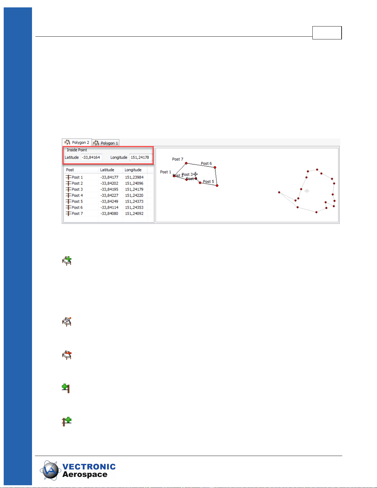
A Virtual Fence consists of several posts and an Inside Point. The Inside point defines
the area of interest; If the point is inside the fence the area of interest is surrounded by
the fence, if the point is outside everything but the fence is area of interest.
The Inside point can be configured with Latitude and Longitude coordinates as you can
see in the figure below.
All fences that are opened at one time can be saved as one Virtual Fence Collection
(.VFC) and can be uploaded to the collar via Link Manager, Handheld Terminal, GSM,
and IRIDIUM.
Figure 16: Combination of two fences. The positions in the left tab define the left fence (bright
red posts).
Creates a polygon with four Posts and an Inside Point. The Posts are the corners of
the Virtual Fence. The Inside Point is a reference of what side of the Fence is
“inside”. If you apply an alternative GPS schedule, this defines if the Virtual Fence
schedule is applied while the collar is inside the enclosed area or outside.
Edits the name of the fence.
Deletes the opened fence.
Appends a post to the end of the fence (e.g. Post 8 in Figure above).
Inserts a post before the selected post.
© 2017 VECTRONIC Aerospace GmbH

The VERTEX Plus Collar 28
Edits the selected fence post. A new window will open (Figure below), in which
you can edit the post’s coordinates and name. The post you are currently editing
is highlighted in green in the fence schematic.
Removes the selected post from the fence.
Figure 17: Post editing window
3.6.1.1 Virtual Fence in Google Earth
Create a polygon using in Google Earth.
Click the left mouse button to set a post. Click several times to build a fence.
© 2017 VECTRONIC Aerospace GmbH

Figure 18: Google Earth - Creating a Virtual Fence
The VERTEX Plus Collar 29
Convert it into a KML file: File - Save - Saving As
Import it in GPS Plus X under: collar – configuration - Virtual Fence Polygons
In GPS Plus X:
Imports a .KML file from Google Earth into the Virtual Fence Editor. The corners of
the polygon will be imported as posts.
© 2017 VECTRONIC Aerospace GmbH

Exports a fence (active fence only, not the complete Virtual Fence Collection) as
.KML file to view in Google Earth.
Please note: Sending Virtual Fences via cable and remotely makes a difference. Via
cable and Handheld Terminal, you can send up to 4000 bytes, approximately 600 posts.
Via Iridium message the collection is limited to 15 posts. You will get an error message
if you exceed the maximum data size.
3.7 Drop Off
Drop Offs allow retrieving the collar without having to recapture the animal.
There are two optional Drop Offs available:
- Timer-controlled Drop Off: The collar is released after a pre-defined period of time
(relative mode, e.g. 100 weeks) or at a pre-defined date and time (absolute mode, e.g.
01 April 2017). The lifetime of the Drop Off is up to five years after production. The
countdown in relative mode starts after removing the Drop Off magnet.
The VERTEX Plus Collar 30
- Radio-and-timer-controlled Drop Off: The collar is released on demand by UHF
radio signal. For the release an UHF Handheld Terminal Version 5 or higher or a Drop
Off Release Transmitter is needed. The maximum distance is about 500 m (For more
information please refer to the Drop Off Release Transmitter manual). Additional timer
control (relative or absolute mode) functions as backup. The lifetime of this Drop Off is
up to 4 years after production.
Figure 19: Drop Off magnet for standby mode
© 2017 VECTRONIC Aerospace GmbH

Figure 20: Drop Off release sites, magnet removed
3.8 External Sensors
It is only possible to have communication between your VERTEX Plus Collar and
several external sensors if your collar has UHF Radio Communication. Data from these
transmitting sensors are stored into the VERTEX Plus Collars internal memory. All
external sensors share the same UHF receiver in the collar, and several sensors can be
used simultaneously.
The VERTEX Plus Collar 31
Please refer to the following subtopics to get more information regarding external
sensors:
UHF ID Tags
Expandable Collars
Vaginal Implant Transmitter (VIT)
Mortality Implant Transmitter (MIT)
3.8.1 UHF ID Tags
The UHF-ID Tags provide data on animal interactions such as Proximity and
Separation. ID tags can be deployed to a belt, an expandable fawn collar or they can be
integrated into a VERTEX Plus Collar. There is also the possibility for a stationary UHFID Tag. ID Tags can be equipped with a mortality sensor and a VHF beacon
transmitter.
Depending on the application, different data is transmitted between the ID tag and the
VERTEX Plus Collar. The signal of external UHF ID tag is received and recorded using
the UHF data communication in a VERTEX Plus Collar. Please refer also to chapter
Internal Sensors Proximity and Separation Sensor and Expandable Fawn Collars.
IDs signal output can be adjusted to the needs of your study.
© 2017 VECTRONIC Aerospace GmbH

For more information please contact our customer service.
3.8.2 Expandable Fawn Collars
Expandable Fawn Collars can be equipped with UHF ID Tags. The Expandable Fawn
Collar is very light and made of elastic material which is folded in several layers. The
layers are sewed together with cotton yarns which allow the layers to unfold with the
effects from wear, time and weather. The combination of elastic and folded material
ensures a good fit for the growing neck of a calf.
The Expandable Collars can be customized; accordingly, their design highly depends on
the species. For further information please contact our customer service.
The VERTEX Plus Collar 32
Figure 21: Left: expandable Survey collar for a moose. Right: expandable ID-Tag as a fawn
3.8.3 Vaginal Implant Transmitter (VIT)
The Vaginal Implant Transmitter (VIT) is used to observe the pregnancy and the birth
event of a collared animal. The VIT informs the researcher about the date and location of
the calving site and provides physiological data during the whole pregnancy. VIT
measures and optionally stores the temperature and motion and defines its status. The
VIT transmits this data with its unique ID to the collar which will initiate the alert
notifications in case of birth event or separation. We offer 2 different sizes suitable for
medium (e.g. deer) and large (e.g. moose) species.
collar
© 2017 VECTRONIC Aerospace GmbH

The VERTEX Plus Collar 33
Figure22: Moose sized VIT (left) and deer sized VIT (right)
Birth detection: When the VIT is pushed out of the mother's body, two things are
expected to happen: The temperature around the VIT will most likely drop and the
motions will stop. When this happens, the VERTEX Plus Collar will recognize a birth
event which will conduct an unscheduled GPS fix and send an alert notification to the
researcher.
Separation: The VIT continuously transmits an ID signal via UHF frequency to the
VERTEX Plus Collar. When the mother moves away from the calving site, the ID signal
is not received any longer. The VERTEX Plus Collar will send a separation message
after one hour has passed without detecting the ID signal (default settings).
Localization: To locate the calving site, the VIT is equipped with a VHF beacon
transmitter. The VHF can be programmed as flexibly as the one in the GPS collar.
3.8.4 Mortality Implant Transmitter (MIT)
The MIT is designed to inform you immediately if your study animal has died. The
Mortality Implant Transmitter is a stainless steel tube which can be placed either into the
rumen or into the abdominal cavity of the animal. For the latter a surgery is needed and it
is only recommended for non-ruminants or ruminants with a small esophagus/rumen.
The MIT contains a highly sensitive acceleration sensor and a temperature sensor.
Unlike the mortality sensor inside VERTEX Plus Collar, the MIT is able to detect the
heartbeat of the animal. The MIT frequently sends status messages of the animal to the
GPS collar using UHF communication. With each position message, the most recent
© 2017 VECTRONIC Aerospace GmbH

The VERTEX Plus Collar 34
body temperature and the status (alive/dead) can be sent remotely as well. Optionally
the GPS collar can send a separate mortality message.
Heartbeat and motion: A highly sensitive acceleration sensor detects the slightest
movements like heartbeat or breathing. If no motion has been detected for a user
definable period of time, the animal is presumed dead and a mortality alert with the
current GPS position data is sent. The VERTEX Plus Collar's VHF beacon will also
switch to mortality mode.
Temperature: Body temperature is measured with an accuracy of 0.1°C. Following
pre-defined intervals, the temperature is sent to the VERTEX Plus Collar and stored in
the collar memory.
4 Data formats
GPS position information: Date and time, latitude/longitude/height, DOP, 2D/3D
navigation, number of used satellites, satellite PRN code and carrier to noise ratio, main
and VHF beacon battery voltage, temperature. Data can be accessed with GPS Plus X.
Temperature: Date and time, logging same as GPS fixes or activity sampling interval.
Temperature is stored with the GPS and the activity data in the .GDF and .binv2 files.
Figure 23: Mortality Implant Transmitter (MIT)
Activity: Date and time, different activity modes measuring acceleration on 3 axes
(X,Y,Z). Activity is stored as .binv2 file and can be accessed with the Acceleration Data
Viewer software.
GSM information: Time and date of GSM communication, RSSI (received signal
© 2017 VECTRONIC Aerospace GmbH

Data formats 35
.GDF
GPS Data File
Binary coded GPS fix data from the collar including
main battery voltage, VHF beacon battery voltage,
and temperature. The file name consists of the collar
number and the time stamp of the file creation coded
as “yyyymmddhhmmss”.
.binv2
Activity Data File
Activity raw data from collar including activity
(acceleration) and temperature.
.SMS
GSM Message File
Contains one GSM or part of a Globalstar/ Iridium
message with GPS data. The file name consists of
the collar number and the time stamp of the SMS
coded as “yymmddhhmmss”.
.PRX
Proximity Sensor Data
Contains data from proximity sensor including signal
strength and time stamp.
.TXT
ASCII
Visually readable equidistant table, compatible to
conventional text editors and spreadsheets
.CSV
Spreadsheet
Computer readable table, compatible to
conventional text editors and spreadsheets
.DBF
DBase Table
Database format, compatible to conventional
spreadsheets and most text editors
.GPX
GPS Exchange Format
File for data exchange with GPS devices
.KML
KML
Google Earth file to display tracks, points of
interest…
.KMZ
KMZ
Zipped Google Earth file
.BTX
BioTelemetry eXchange
VECTRONIC-defined XML-format
.GDX
GPS Data eXchange
Is a XML format defined by VECTRONIC
strength indicator), and bit error rate. This information is stored in every SMS.
Mortality information: Date and time of a mortality event based on the activity of the
animal.
List of files and extensions used
Download files
Export files
© 2017 VECTRONIC Aerospace GmbH

Aerospace, which will make it easier to exchange
acquired data over system boundaries. It is an
internal format of GPS PLUS X and can also be
used as import format.
.VFC
Virtual Fence
Virtual Fence Collection
.binv2
Acceleration
Is a format which can be read of the VECTRONIC
software Acceleration Data Viewer.
.ADF
2-axis Activity Data File
.ADF3
3-axis Activity Data File
Upload files
.vbsf
Beacon Schedule File
VHF beacon schedule of VERTEX Plus Collar
.vgsf
GPS Schedule File
GPS schedule of VERTEX Plus Collar
.vcsf
Communication Schedule File
Communication Schedule of VERTEX Plus
Collar
.vesf
External Sensor Schedule File
External Sensor Receiver Schedule file
.vfc
Virtual Fence Collection
Coordinates for Virtual Fences
.bin
Collar Firmware File
contains firmware for VERTEX Plus Collars
.key
Collar Key File
contains a key for one collar, needed to register
the collar in the GPS Plus X and to manage its
data
.txt
Collar Info File
contains all information on the collar configuration
Data formats 36
Hardware information files
© 2017 VECTRONIC Aerospace GmbH

5 System Set-up
The following sub chapters explain what you need to do before you can check and test
your collar.
Software Installation
Collar Registration
USB to VERTEX Plus Interface Cable
Test the collar
5.1 User-Software Installation
All VECTRONIC collars are managed with our free software GPS Plus X which you can
find on the collar user-CD. It also can be downloaded from our homepage
(www.vectronic-aerospace.com). The auto-installer includes an Installation Wizard which
will guide you through the installation and setup.
System Set-up 37
The installation procedure will ask you for a destination directory and suggest a default
directory. You can now decide whether you want to install one of the following software
packages (list might vary with program versions):
User Interface: Collar communication and configuration
Data Storage Service: Data management, visualization and export
Data Collector Service: Data reception and distribution
TeamViewerQS VAS: Tool for remote desktop support
GPS Plus X Manual: integrated Manual
If you want more information to the software program please refer to GPS Plus X
Manual. (If you opened GPS Plus X just click "Help" or to get linked.)
5.2 Collar Registration
To be able to configure the collars and to process data and messages with the GPS
Plus X software, you need to register the collars. The keys for each collar will be
provided with the User-CD which came with the collars.
For registering the collar, please go to the Configuration frame in GPS Plus X and
select Configuration Collars.
© 2017 VECTRONIC Aerospace GmbH

System Set-up 38
Figure 24: Collar List
In the appearing window “Collar List”, press to add a new collar to the list. After
clicking the button, the Collar Properties Editor appears. To register a collar, click
. An open file dialog will open and you can select the collar registration key for
the collar (to be found in the folder Resources\Collar and Drop Off Keys).
Figure 25: registering the collar
If you add the details before registering the collar, the registration status of the collar will
be invalid. After registration, the entry of the corresponding collar will change from invalid
to valid. For more information on collar registration, refer to the GPS Plus X Manual.
© 2017 VECTRONIC Aerospace GmbH

5.3 USB to VERTEX Plus Interface Cable
After you have registered the collar, you will be able to communicate with the collar using
the USB to VERTEX Plus Interface Cable.
System Set-up 39
Figure 26: USB to VERTEX Plus Interface Cable
NOTE: Please do not use any other cables than the USB to VERTEX Interface Cable to
connect your VERTEX Plus Collar to your computer. You may destroy the
communication connector of the collar which makes it impossible to load or upload data
and schedules directly.
When you have installed and started the software GPS Plus X, registered your collar
and connected your collar to the computer it appears in the software in frame 'Devices'.
This action is optional. But it is recommended to get familiar with your collar settings and
to check them before testing and deploying. Please refer also to chapter Collar Main
Tree.
© 2017 VECTRONIC Aerospace GmbH

5.4 Test the Collar
It is recommended to test the collar in advance to confirm if GPS positions are received
and transmitted as programmed before you deploy it on the animal.
System Set-up 40
Figure 27: Devices
1. Remove the magnet from the electronic housing (not the Drop Off magnet!)
2. Place them outdoors with clear view to the sky (NOTE: Place the collars about 1m
apart otherwise their signals might interfere and affect the testing)
3. Listen for the VHF beacon signal with your tracking receiver (NOTE: check settings
for frequency and communication windows for beacon before)
4. Wait for incoming messages (NOTE: check for expected time frames first)
5. Process incoming data and check signal quality etc.
6. Send reconfiguration commands remotely
7. Deactivate the collar by reattaching the magnet to the electronic housing to complete
the testing
NOTE: To save battery life, leave the magnet on the collar during storage and do not
leave the collar connected to your computer if you do not use it. Disconnect the battery
pack if you store the collar for months.
6 Collar Main Tree
Devices VERTEX Plus Collar
© 2017 VECTRONIC Aerospace GmbH

Collar Main Tree 41
The Devices frame is the main tool to manage your VERTEX Plus Collar in any respect.
In the following chapter you get more information about all available options for your
VERTEX Plus Collar, such as data download, data upload and configuration.
The first node (Information) contains reports about hardware and the actual settings of
the collar. It also enables testing its basic functionality.
The second node (Configuration) includes all user configurations for the collar.
The third node (Schedules) is where you can define and upload schedules.
The fourth node (Collected Data) gives you the option to download data once you
retrieve the collar after its deployment.
6.1 Information
Devices VERTEX Plus Collar Information
The Information Node contains all actual hardware and programming settings of the
collar and its functionality.
Figure28: Collar Main Tree
© 2017 VECTRONIC Aerospace GmbH

Collar Main Tree 42
Please refer to following subtopics of the Information Node:
Telemetry
GPS Monitor
Info File
6.1.1 Telemetry
Devices VERTEX Plus Collar Information Telemetry
The Telemetry window gives an overview about all hardware and software settings of the
collar. It shows the actual programming with no option to change it here. This topic
informs you about definitions used in the Telemetry window.
Figure 29: Main Tree- Information Node
© 2017 VECTRONIC Aerospace GmbH

Collar Main Tree 43
Figure 30: VERTEX Plus Collar Telemetry
© 2017 VECTRONIC Aerospace GmbH

Collar Main Tree 44
Telemetry window definitions
System Tab:
Collar production number, production date, Printed Circuit Board
(PCB) type and collar ID
Time collar time in UTC and the UTC correction, configured to the
collar
Firmware information about the collar firmware: Bootloader and Firmware
information- Internal or service related information only
Internal Sensors main voltage and the ambient temperature of the included
mortality sensor. The voltage is an important value to estimate
the battery power status of the collar
Data Memory (mb) memory capacity of the non-volatile on-board storage in
megabyte
Sensors Tab:
GPS information about the GPS Mode (internal usage only), GPS Max
Fix Time in seconds, GPS Fix Count (number of fixes collected
so far) and the GPS skip Count. The latter meaning to put only
selected fixes into the transmission data (e.g. every second fix)
and leave the rest for USB data download only.
Mortality shows mortality period (period without acceleration to trigger
mortality alert)
Hibernation wake-up level defines the activity threshold when Hibernation
Mode is over (predefined values depending on the species)
Acceleration 3 modes to define the acceleration sensor: off(0), basic(1),
advanced(2).
Sample Count shows how many data are actually saved on
board. Sensor Range defines the accuracy of the acceleration
data
recording Sample Rate Select defines how many measurements
the sensor takes per second
Temperature defines if temperature sensor is on / off
Communication Tab:
Radio information about the Transmit Frequency, Receive Frequency
and Transmit Power of the collar
© 2017 VECTRONIC Aerospace GmbH

Collar Main Tree 45
Globalstar amount of Globalstar communication attempts per position and
the ESN number
Iridium fixes per message (user-definable) and IMEI number of the collar
(potentially needed in collar registration)
GSM mode, destination number, and the reception delay which
defines the delay until the GSM modem starts to send data
Beacon Tab:
Beacon Frequency frequency of the VHF beacon: the default frequency which was
set by VECTRONIC Aerospace and the User defined frequency
values of the beacon min. frequency and the Beacon max.
frequency are shown
Beacon Power VHF Beacon output Power
Patterns information about the Standard Pattern as well as the Mortality
Pattern of the VHF beacon
also includes the Default Pattern which was set by VECTRONIC
Aerospace and the User Pattern if it is configured
Sensor Communication Tab:
Repetition Interval defines how often the collar transmits its UHF ID
Proximity Transmitter shows if it is on / off, transmit frequency, and transmit power
External Sensors Tab:
Listen Interval how often does the collar listen for a signal (transmitted from an
external sensor)
MIT/VIT/SEP Status Transmitter
transmit status: Temperature, latest receive (current state)
Proximity Receiver Listen Duration: time span the collar listens for a signal
Start / End times: At which times of the day the sensor listens for
a signal
Shows the sensitivity of the proximity receiver in dbm
ID Blacklist: Fill in Collar ID's (for explanation always refer to
User Configuration Sensor Communication- External Sensor-
© 2017 VECTRONIC Aerospace GmbH

MIT / VIT / SEP Receiver
Collar Main Tree 46
Proximity Receiver)
ID Whitelist: Fill in Collar ID's (for explanation always refer to
User Configuration Sensor Communication- External Sensor
Proximity Receiver)
Active Duration: time period how long the schedule is active
once the collars (ID Tags) are separated again.
Skip Count: How many proximity GPS fixes actually will be sent
Sample Count: How many Proximity data are stored
Listen Duration: defines how long the collar listens for a signal
Start/ End time: At which times of the day time the sensor listens
for a signal
No Contact Delay: defines the delay when the contact has been
lost.
Virtual Fence Tab:
VF Mode shows the actual VF mode of your collar
VF Retransmit Interval defines when the message is sent again, just to secure it will be
For more detailed explanations, notifications, and recommendations please refer to
User Configurations
6.1.2 GPS Monitor
Devices VERTEX Plus Collar Information GPS Monitor
The GPS monitor function allows you to check the GPS receiver. There are two options
in this frame, GPS Warmstart and a GPS Coldstart. Both commands should only be used
for diagnostics and outside of buildings with open view to the sky.
ID: shows the ID/ the ID's
Sample Count: How many data are stored
received
GPS Warmstart: This button will initiate a warmstart of the collar. The GPS receiver
will use the Ephemerides and other data already stored in the collar (flash memory,
remains there for roughly 2hours) and only complete them with actual satellite data.
© 2017 VECTRONIC Aerospace GmbH

Collar Main Tree 47
Depending on what is already stored, it can be fast or take some time. You can abort
the Warmstart by changing the node.
GPS Coldstart: The command is quite similar to the GPS warmstart command. The
GPS receiver will skip its potentially stored Ephemerides and download every available
data from the GPS satellites anew. It will take much longer to acquire a GPS location.
A GPS coldstart is necessary if you changed the battery pack of your collar.
The process is done if the dataflow stops. (GPS position is set and time does not
change anymore.) This Process takes a few minutes.
6.1.3 Info File
Devices VERTEX Plus Collar Information Info File
The collar info file includes all information on the collar configuration. It can be saved
as .TXT (file extension) file or printed directly. It contains technical information of the
collar as well as all schedules and the Virtual Fence collection. You can see which
schedule is used at the moment. If you did not program a schedule yet the default
schedule is active. Every schedule is shown in a version which can be easily read and in
the .XML format which is machine readable. Below you can see an extract of an Info File
of the VERTEX Plus Collar.
Recommendation: Create and save a new Info-Sheet whenever you have the collar at
hand and did any changes, especially before deployments.
Figure 31: GPS Monitor after fix has been obtained
© 2017 VECTRONIC Aerospace GmbH

Collar Main Tree 48
For definitions of terms used in the Info File please refer to Telemetry.
6.2 Configuration
Devices VERTEX Plus Collar Configuration
Figure 32: Info File
© 2017 VECTRONIC Aerospace GmbH

Collar Main Tree 49
In the Configuration node you can change the user-definable configurations of your
collar.
Please refer to following subtopics of the Configuration Node:
User Configuration
Time
Virtual Fence Polygons
Start Bootloader
6.2.1 User Configuration
Devices VERTEX Plus Collar Configuration User Configuration
In this frame you can change the user-definable configurations of your collar. The actual
configurations can be seen in the collar’s Telemetry and in the Info File. Faulty entries
(e.g. faulty UTC correction) will automatically be reset back to the factory settings
defined by VECTRONIC Aerospace.
When configuring different settings, a small window will appear whenever marking a
parameter you are about to change (see below). In this window, the range of possible
values to choose will appear (Min value and Max value). Depending on the kind of data
which is edited, the window shows different values.
Figure 33: Main Tree- Configuration Node
© 2017 VECTRONIC Aerospace GmbH

Collar Main Tree 50
Figure 34: User Configs- Min and Max value
You can define the following parameters:
System
UTC correction The collars use the UTC (Universal Time Coordinated) time
which is also used by the GPS satellite system. It differs to your
LMT (Local Mean Time). To give an example: LMT in Germany
is +2 hours to UTC, UTC correction: +2 hours. You can set the
UTC Correction in GPS Plus X and the collar will then translate
your time in LMT programmed schedules internally.
Recommendation: Stick to either way (UTC correction or
UTC schedules) for all collars and document it carefully. It is
easy to get confused, especially if you ask us to do some
changes.
Sensors
GPS Skip Count GPS skip count refers to the satellite communication enabling
you to set a number of GPS location which will be conducted
and stored but are not added to the transmission pool.
Mortality Period Here you can set a time span using the up- and down arrows. If
no activity is recorded (activity sensor) during the set time span
the animal is assumed to be dead and a mortality event is
triggered. The default value is 24h which has been successfully
used in many studies.
NOTE: Please consider which values might reflect animal
behavior at best. A short period might lead to false alarms as
the animal is only resting.
Hibernation Period You can define the time after which the collar switches back to
normal mode if the activity is higher than the wake-up
threshold.
© 2017 VECTRONIC Aerospace GmbH

Collar Main Tree 51
Acceleration Here you can define the accuracy of your acceleration data.
The more accurate your data, the more storage you need.
You also can select a Recording Sample Rate. You can choose
between 2, 4, 8, 16, 32 records per second.
Communication
Globalstar You can change the positions per message.
Recommendation: 1 Fix per message
Iridium The Iridium Mode (1-18) defines the number of fixes per Iridium
message. Please refer to Iridium Communication for
information about message set-up and size.
Recommendation: 4 Fixes per message
GSM The GSM Mode defines number of fixes per SMS.
Recommendation: 8 fixes per message with VAS SIM
chips
7 fixes per message with SIM cards
from your own provider
You can change the destination address of all incoming
messages. By default, it will be the number of VECTRONIC
ground station. If you are using your own ground station your
own mobile number is setup here.
You can configure the Reception Delay which depends on the
providers delay. The GSM module in the collar will be booked
in the network for additional time to receive messages.
Beacon
Beacon Frequency Choose the frequency of your VHF beacon by simply typing it
into the field. You can only select frequency values between the
minimum and maximum value which are hardware defined
(shown in the small pop up window).
NOTE: Signal strength is best with the primarily set value
(hardware dependent), signal strength will slightly decrease at
the rim.
© 2017 VECTRONIC Aerospace GmbH

Collar Main Tree 52
Beacon Power Recommendation: Stick to the default value of 10dBm unless
we have specifically adjusted this for you. It offers the optimum
balance between signal strength and energy consumption. Do
not hesitate to ask us if you have questions.
Mortality Beacon The Mortality beacon is switched on during the defined beacon
schedule. The Default setting is: [0] always on.
Beacon Patterns In both Beacon Modes, (Standard and Mortality) you can
configure the patterns. You can set the pulse length in
milliseconds (ms) and the Loop Length in ms. For more
information please refer to VHF Beacon.
NOTE: The default settings have been successfully used in
many studies. Changes will affect battery consumption.
NOTE: The Emergency Pattern is not user definable.
Sensor Communication
Proximity Tag Recommendation: Stick to the default value of 10dBm. It
offers the optimum balance between signal strength and energy
consumption.
External Sensors
Listen Interval You can choose the time interval when the collar listens for a
signal.
Status Transmission The status includes temperature and latest receive (current
state) of data sent from an external sensor.
Proximity Receiver Listen Duration: The collar listens for e.g. 1500ms (1.5s) every
10 min (listen interval).
Start/Endtime: Shows at which times of the day the sensor
listens for a signal.
Shows the sensitivity of the proximity receiver in dbm.
ID Blacklist: Shows which ID Tags will be ignored if a signal is
received.
ID Whitelist: Shows which ID Tag contact will create a reaction
immediately.
© 2017 VECTRONIC Aerospace GmbH

MIT / VIT / SEP Receiver
Collar Main Tree 53
(change of GPS schedule)
Active Duration: Shows the activity time of the schedule once
the collars (IDTags) are separated again.
Skip Count: How many proximity GPS fixes actually will be sent
(Skip Count 3: Every third fix will be sent).
Sample Count: Shows how many Proximity data are stored.
NOTE: ID Tags which are not on Blacklist/ Whitelist: contact is
recorded but no reaction is created. If no ID Tags are listed,
every contact will create a reaction.
Start/ End time: Shows at which times of the day the sensor
listens for a signal.
No Contact Delay: Defines the delay when the contact has
been lost. (e.g. (VIT) set a delay to finally know when mother
leaves birthplace)
ID: fill in the ID's of your external sensors.
Listen Duration: Low value- Expend less battery power but
lower chance to receive a signal.
High value- Requires more battery power and
high chance of receiving signal.
Recommendation: Stick to the default settings.
Virtual Fence
Mode Shows 1 out of 5 modes: [0] Off, [1] On -No Message, [2] On -
Message On Enter, [3] On -Message On Leave, [4] On Message On Enter And Leave the Virtual Fence.
Retransmit Interval Defines when a second message is sent, just to secure it will
be received.
Recommendation: If you urgently need the information that
your animal enters an area do not wait too long to secure your
message will be received. Do not hesitate to ask us for further
information.
If you have a problem understanding the vocabulary of this topic you will find some
definitions at Telemetry (Telemetry window definitions)
© 2017 VECTRONIC Aerospace GmbH

For more information please read the VERTEX Plus Collar Chapter carefully or just
contact our customer service.
6.2.2 Time
Devices VERTEX Plus Collar Configuration Time
The Time frame displays:
- Current Collar Time (UTC: Time, Date)
- PC Time (Time, Date)
- New Collar Time (UTC) which is definable for you: If the Current Collar Time is
incorrect please correct it by setting the New Collar Time (Time, Date)
- Computer UTC Correction
After you have provided your time changes press to send the new time
Collar Main Tree 54
setting to your collar. With you can reload the configuration from the collar.
NOTE: With each successful GPS fix, the collar time is automatically adjusted to the
correct UTC time. UTC correction will be only applied for schedules and time of the day
settings. Also, UTC correction cannot be enabled by sending the local mean time to the
collar.
Figure 35: Set Time
© 2017 VECTRONIC Aerospace GmbH

6.2.3 Virtual Fence Polygons
Devices VERTEX Plus Collar Configuration Virtual Fence
Polygons
The virtual fence allows you to use a different GPS schedule in a certain area (Virtual
Fence). To do this, you need to define a virtual fence around this area and assign a
Virtual Fence schedule to it. You can create a new fence by defining up to 62 posts
(max. binary size 385 byte, see below for details).
Collar Main Tree 55
Figure 36: Virtual Fence Window
There are two ways to create a polygon. You can use the Virtual Fence editor in the
GPS Plus software and define fence posts by their coordinates. Alternatively, you can
create a polygon in Google Earth and import the .KML file into GPS Plus X. A Virtual
Fence Collection can contain several single fenced areas (“polygons”). Each fence will
be created and edited on its own tab, but all opened fences are shown in all tabs. The
fence that belongs to the opened tab is marked with bright red posts. All fences that are
opened at one time can be saved as Virtual Fence Collections (.VFC) and can be
uploaded to the collar via cable, UHF Handheld Terminal, GSM, and Iridium. For
detailed information on shapes, combinations of several polygons of a Virtual Fence
refer to 7.2.6 Functionality of sensors: Virtual Fence.
© 2017 VECTRONIC Aerospace GmbH

Collar Main Tree 56
Add a Fence: You can add a fence to the fence collection by clicking on the icon or
calling Add Fence… in the Fences menu.
Edit Fence name: The currently selected fence can be renamed with this option.
Click on the icon or use Edit Fence… in the Fences menu.
Remove Fence: The currently selected fence will be removed from the Fence
Collection. You will be asked for a confirmation before this command is executed. Click
on the icon or use Remove Fence… in the Fences menu.
Append Post: Appending a post will add a post to the end of the list of the current
fence. A dialogue will open where you have to enter a name for the post (by default “Post
x”) and the coordinates. Click on the icon or use Remove Fence… in the Posts menu.
Insert Post: Inserting a post will only work if another post from the list is selected. A
new post will be inserted before the currently selected post just like appending a post if
you click in the icon or select Insert Post… in the Posts menu.
Edit Post: You can edit each fence post by double clicking on it, by clicking on the
icon, or by clicking on Edit Post… in the Posts menu.
Remove Post: The currently selected post will be removed without further
confirmation if you click on the icon or by selecting Remove Post… in the Posts menu.
To rearrange posts, you can drag & drop them in the list of the current fence.
Importing and Exporting Virtual Fences from Google Earth
You can create a polygon in Google Earth, save it as .KML file, and import it into GPS
Plus. Please make sure that you use the command Add Polygon in Google Earth.
Import KML polygon as Fence: Imports a polygon created in Google Earth from a
.KML file into GPS Plus. You can do this by clicking on the item or Import Fence… from
the Files menu. The name of the file will be the name of the fence. If you have multiple
polygons in the .KML file, only the first will be imported.
© 2017 VECTRONIC Aerospace GmbH

Collar Main Tree 57
Export Fence as KML polygon: Exports a polygon as .KML file to view it in Google
Earth. Click on the icon or select Export Fence… from the Files menu. Polygons are
saved as Virtual Fence Collection (.VFC), which can contain more than one polygon.
The area of the polygon is not necessarily identical with the Virtual Fence area. With the
Inside Point ( - see below) you can define whether the Virtual Fence area is
inside or outside the polygon.
Note: In some cases, the Inside Point might be set automatically not inside the polygon,
but outside (Figure below). Please make sure that the Inside Point is on the correct
position before sending the Virtual Fence to the collar.
Figure 37: Virtual Fence with Inside Point automatically set outside of the polygon
Though you can combine several polygons, you can upload only one Virtual Fence
schedule which will be applied to all Virtual Fences on the collar. The collar can only
distinguish between “inside” and “outside”, so it is “inside polygon 1 and inside polygon
2”, but “inside polygon 1 but not inside polygon 2” is not possible. If the collar is inside at
least one of these polygons it uses the Virtual Fence schedule, otherwise it uses the
standard GPS schedule.
© 2017 VECTRONIC Aerospace GmbH
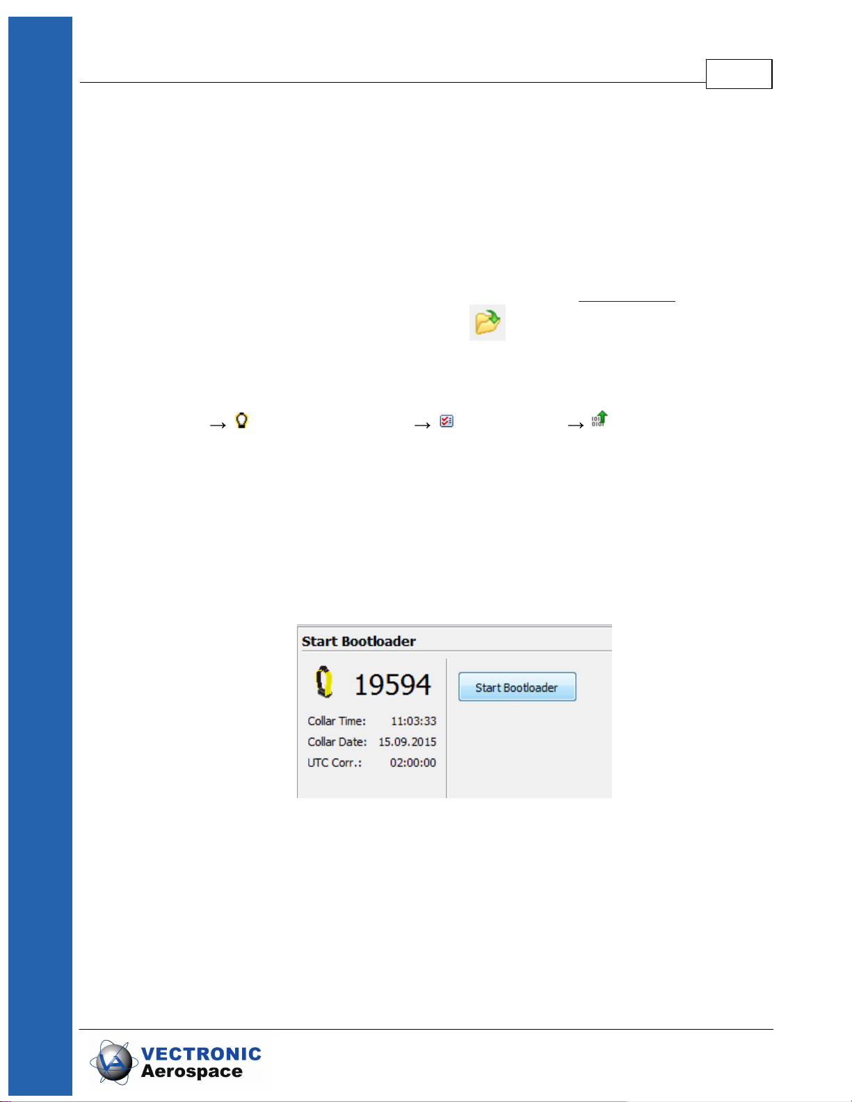
If you transfer the VFC via Iridium or GSM, Virtual Fence collection and GPS schedule
must be transferred in one message, so both files have to be smaller. For Iridium or
GSM 7-bit coding, the maximum size of the two files is 129 bytes, for GSM 6-bit coding,
the maximum size of the two files is 109 bytes.
Select a Virtual Fence Collection and one GPS schedule which will be applied to all
virtual fences in the collection. Press Send to upload it to your collar.
It is possible to program the collar to send a message via GSM or Iridium whenever the
animal enters and/or leaves the Virtual Fence (for details see Virtual Fence).
To upload a Virtual Fence to your collar press to browse your computer for a .VFC
file.
6.2.4 Start Bootloader
Devices VERTEX Plus Collar Configuration Start Bootloader
It might be necessary to update the firmware of your collar. Therefore, use the Start
Bootloader frame. You should not do this unless you experience problems with the
current collar firmware or need a feature only available in a newer version than the
present one. In this case, get the appropriate file from VECTRONIC Aerospace and
start the Bootloader.
Collar Main Tree 58
To upload new firmware the collar has to be deactivated - so please attach the
magnet to the electronic housing.
Figure 38: Start Bootloader
A notification window will appear to inform you that your collar switches the mode to be
able to change firmware settings (e.g. firmware updates).
© 2017 VECTRONIC Aerospace GmbH

Figure 39: Switch to Bootloader Mode
Collar Main Tree 59
Figure 40: Bootloader Mode
First, you need to upload the new firmware. Click on "Firmware Upload" and browse (
) your computer for the firmware file you got from VECTRONIC and click the 'Start'
button.
© 2017 VECTRONIC Aerospace GmbH

Collar Main Tree 60
Figure 41: Upload Firmware
When the upload process is finished, click on "Start Firmware" and the collar will switch
back to 'Normal mode'.
Figure42: Start Firmware
© 2017 VECTRONIC Aerospace GmbH

6.3 Schedules
Devices VERTEX Plus Collar Schedules
Schedules define when the respective sensor is on. That means you can precisely
decide when certain sensors of your collar send, receive or record information. To
create new or change already existing schedules click on the Collar Main Tree and open
the Schedules node. There you can see all available options which you can create
schedules for. It always requires battery power to send, receive, or record data so you
should spend some serious thoughts on schedules before collar deployment.
Collar Main Tree 61
Figure 43: Switch back to Normal Mode
VERTEX Plus Globalstar: You cannot upload schedules via satellite due to the one-way
communication system.
© 2017 VECTRONIC Aerospace GmbH
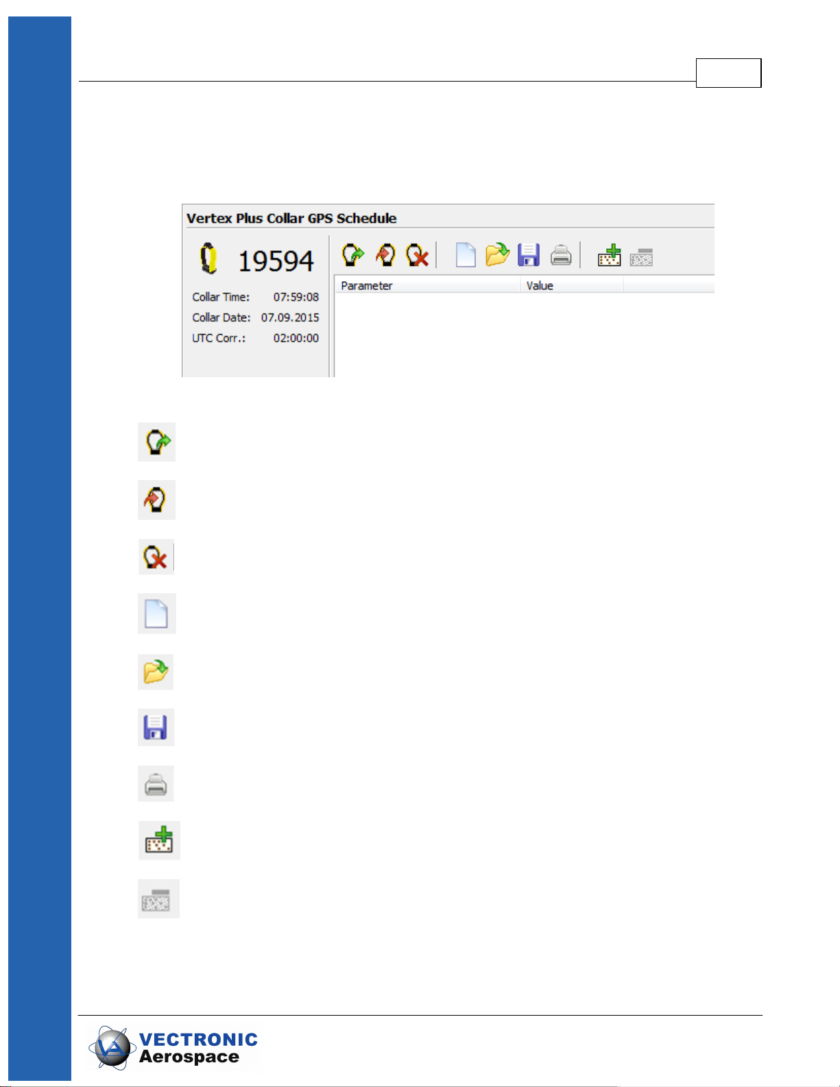
Collar Main Tree 62
Figure 44: Main Tree- Schedules Node
To create a new schedule, you will need basic knowledge regarding major buttons and
schedule rules, which are described in the following:
Figure 45: Schedule Creation Window
Load schedule from collar
Upload created schedule to the collar
Erases the collar schedule
Clears the tool window to start schedule
Loads a previously saved schedule
Saves a created schedule for later usage and control
Prints out the listed rules
Schedule builder tool: add a new rule
Schedule builder tool: delete selected rule
© 2017 VECTRONIC Aerospace GmbH

Collar Main Tree 63
All schedules consist of one or more rules specifying the date and time when the
appropriate sensor of the collar will be active. Each schedule consists of a varying set of
rules:
Start Date the date when the rule should start
End Date the date when the rule should end
Period Length the length of the period in which the Sequence for recording is
repeated
Sequence The sequence is a time span within the period length in which
you like to record data. Here you can define:
Offset – it defines the time span between the start of the period
and the first recording of data
Duration – period in which the data will be recorded with the
Rate repetition
Rate – data recording repetition rate
NOTE: You can only record data within the time span of the period. This way, the sum of
offset and duration must be smaller than the value of the defined period length.
© 2017 VECTRONIC Aerospace GmbH

Collar Main Tree 64
Figure 46: Schedule Rules
If you want to create a new schedule for the first time (only the default schedule exists in
the collar), a notification window appears when selecting the schedule frame.
Figure 47: Notification- Default schedule
Please refer to following subtopics of the Schedules Node for deeper information
© 2017 VECTRONIC Aerospace GmbH

regarding single schedule creation possibilities:
GPS & Beacon Files Upload
GPS
Beacon
Communication
External Sensor Receiver
Proximity GPS
Virtual Fence
6.3.1 GPS & Beacon Files Upload
Collar Main Tree 65
Devices VERTEX Plus Collar Schedules GPS & Beacon Files
Upload
This option is only useful if you already created GPS or beacon schedule files
beforehand and want to upload them to your collar (otherwise you can skip to the next
subtopic GPS Schedule). To upload a GPS and/or Beacon file tick the appropriate
check box. Browse ( ) your computer for a schedule file (.vgsf / .vbsf) and upload (
) the configuration to the collar. You have no option to cross-check the
schedules again so you should be well experienced to use this feature.
This feature speeds up the process of loading schedules to collars.
6.3.2 GPS Schedule
Devices VERTEX Plus Collar Schedules GPS
For general schedule creation rules and hints check the main topic of this chapter
(Schedules)
You can use up to 292 rules within one schedule and get as complex as you want (rules
for all biological- and physical seasons, planned field operation, different study or
monitoring questions etc). It highly depends on your studies and the species how many
GPS fixes the collar should take per day.
GPS Scheduling differs between the 3 variants of the VERTEX Plus Collar you can have
© 2017 VECTRONIC Aerospace GmbH

(Globalstar / Iridium / GSM).
Collar Main Tree 66
Figure 48: Example GPS Schedule
VERTEX Plus Globalstar:
Due to the Globalstar system setting there is minimal pause of 30 minutes between
different Globalstar transmissions. GPS positions can be recorded more often but data
are in the collar only and not transmitted remotely.
NOTE: For safety reasons you should define at least one schedule starting on
01.01.2000. If the collar's time is reset for any reason, the timer will start at this date and
will attempt to take one fix per week until another schedule starts or until the clock is set
to the correct UTC time by a successful GPS fix.
For more information please refer to Globalstar Communication.
VERTEX Plus Iridium:
The Iridium variant has no limitation for Iridium Transmissions. This means you can get
as many fixes as you like and also vary them along the study period.
You can start with a low number of fixes to get an overview of how many fixes you really
need and how your animal behaves, it is possible to change schedules remotely. But
you should pay attention to the file size of your schedule (Figure: schedule file size), it
© 2017 VECTRONIC Aerospace GmbH

Collar Main Tree 67
has to be smaller than the maximum file size of one Iridium message (109 bits) if you
want to upload the schedule via satellite connection. If the schedule file size is too big for
an Iridium upload there will be an error message when you try to send the file to the
collar.
Figure 49: schedule file size
Recommendation: To make sure you receive GPS fixes of your collar, please program
irregular sequences so that communication attempt does not take place at the same
time every day. (In case of the animal is not reachable for the satellite at a specific
daytime when the satellite tries to reach it, e.g. if a bear hides in a cave around 6pm and
the satellite tries to reach the collar only at 6pm every day.) The worst case is to get
no results at all but you can prevent this with correct scheduling.
NOTE: For safety reasons you should define at least one schedule starting on
01.01.2000. If the collar's time is reset for any reason, the timer will start at this date and
will attempt to take one fix per week until another schedule starts or until the clock is set
to the correct UTC time by a successful GPS fix.
For more information please refer to Iridium Communication.
VERTEX Plus GSM:
You can start with a low number of fixes to get an overview of how many fixes you really
need and how your animal behaves, it is possible to change schedules remotely. But
you should pay attention to the file size of your schedule (Figure: schedule file size), it
has to be smaller than the maximum file size of one Iridium message (109 bits) if you
want to upload the schedule via satellite connection. If the schedule file size is too big for
an Iridium upload there will be an error message when you try to send the file to the
collar.
NOTE: For safety reasons you should define at least one schedule starting on
01.01.2000. If the collar's time is reset for any reason, the timer will start at this date and
will attempt to take one fix per week until another schedule starts or until the clock is set
to the correct UTC time by a successful GPS fix.
© 2017 VECTRONIC Aerospace GmbH

For more information please refer to GSM Communication.
NOTE: The collar will take one GPS fix per week when all schedule rules are in the
future. It will take a GPS fix every four hours when all schedules are outdated.
If you need further help please contact our customer service.
6.3.3 Beacon Schedule
Devices VERTEX Plus Collar Schedules Beacon
For general schedule creation rules and hints check the main topic of this chapter
(Schedules)
The configuration of the VHF Beacon schedule is similar to the configuration of the GPS
schedule but without setting the Fix Rate. You can only set the Start Date and End Date,
Period Length, Offset and Duration. The VHF beacon is active in the time span between
Offset and Duration. For example, if you choose 6 o'clock for the Offset and a Duration
of 4 hours with a Period Length of 1 day, the VHF beacon will be active every day from
6.00 am to 10.00 am. In difference to the GPS schedule, you can define max. 372 VHF
beacon schedule rules.
Collar Main Tree 68
Figure 50: Example Beacon Schedule
© 2017 VECTRONIC Aerospace GmbH

To save battery life, it is important to switch off the beacon during times when you will not
track your animal (e.g. during the night).
After setting up the VHF Beacon schedule, press to send it to the collar.
6.3.4 Communication Schedule
Devices VERTEX Plus Collar Schedules Communication
The Communication Schedule is only available for GSM or Iridium collars.
For general schedule creation rules check the main topic of this chapter (Schedules)
With this feature you can control when the collar tries to contact the satellite to transfer
fixes. It is only necessary to create this schedule if you do not agree with the default
settings which collects 4 fixes and send them instantly in one message.
Recommendation: Do not use the communication schedule unless you know the satellite
reception is very good.
Collar Main Tree 69
6.3.5 External Sensor Receiver Schedule
Devices VERTEX Plus Collar Schedules External Sensor
Receiver
For general schedule creation rules check the main topic of this chapter (Schedules)
The External Sensor Receiver schedule defines when the collar listens for signals sent
by external sensors. The schedule rules are similar to the Beacon schedule: You can
only set the Start Date and End Date, Period Length, Offset and Duration. The External
Sensor Receiver is active in the time span between Offset and Duration.
6.3.6 Proximity GPS Schedule
Devices VERTEX Plus Collar Schedules Proximity GPS
For general schedule creation rules check the main topic of this chapter (Schedules)
You can define a GPS schedule as proximity schedule. It is created and uploaded the
same way as the standard GPS schedule, but you need to select the proximity GPS
schedule node. For information regarding the proximity application please refer to
Proximity Sensor.
© 2017 VECTRONIC Aerospace GmbH

6.3.7 Virtual Fence Schedule
Devices VERTEX Plus Collar Schedules Virtual Fence
For general schedule creation rules check the main topic of this chapter (Schedules)
You can define a GPS schedule as Virtual Fence schedule. It is created and uploaded
the same way as the standard GPS schedule, but you need to select the Virtual Fence
schedule node. For information regarding the Virtual Fence application please refer to
Virtual Fence and Virtual Fence Polygons.
6.4 Collected Data
Devices VERTEX Plus Collar Collected Data
Collar Main Tree 70
Figure 51: Main Tree- Collected Data Node
This frame shows the data retrieval options of the collar.
The main function of this node is to download the collar data. The output window and
functions differ but the main functions are pretty much identical. Following buttons will
appear on the symbol bar in this chapter:
Reads data from the collar and displays it in the frame; this is not done automatically
as the download of data can take several seconds to minutes.
© 2017 VECTRONIC Aerospace GmbH

Collar Main Tree 71
Saves the data to the storage module; we advise to save all data from the collar,
even if you export them as data files.
Saves data to storage module.
Exports acceleration data (.csv).
These commands erase data stored on the collar. From left to
right: GPS position, acceleration, mortality, proximity. Please make sure that you have
stored the data before you use this command. Data cannot be restored once
deleted!
In all subtopics (accept acceleration) there is a filter to restrict the output file to a certain
period and/or also to certain data value attributes.
For further instructions how to save, erase, export and display data please refer to the
GPS Plus X manual and search for 'Downloading Data' and 'Filter'.
7 Remote Collar (Communication)
This chapter deals with the remote communication to the collar after deployment or for
testing the collar using Iridium or GSM communication.
For remote communication go to Devices Remote Collars Vertex Collars
Figure 52: Remote Vertex Collars
Refer to the subtopics to learn how to communicate with the collar remotely.
© 2017 VECTRONIC Aerospace GmbH

Remote Collar (Communication) 72
“GPS Schedule” is used to define and send GPS schedules to one or more collars.
The third node includes the same options for VHF Beacon schedules.
“Communication Schedule” enables you to upload communication schedules defining
communication windows for the collar. To edit schedules please refer to chapter
Schedules.
“Virtual Fence” allows you to browse for Virtual Fence collections you created before
and send them to your collar as explained in Virtual Fence Polygons.
For remote communication with a GSM collar with customer SIM card, a Ground Station
is necessary. If you do not own one, please contact our customer service.
For remote communication with an Iridium collar you need to set further configurations
(email address,...) to communicate with your collar. Therefore, refer to the GPS Plus X
software manual and search for “Collar Command Destinations”.
The steps to send out commands to your collar are explained in the GPS Plus X
software manual, please search for “Remote communication via GSM and IRIDIUM”.
NOTE: Check changes carefully before sending them as you might have problems to
change them again (e.g. adding skip count, raising positions / messages fewer
messages from the collar, fewer communication windows for you).
NOTE: Make sure you have chosen the correct collars only.
NOTE: Please keep track on your changes (collar journal) for you and your planning but
also for us if you need support at some point.
7.1 Remote User Configuration
Devices Remote Collars VERTEX Collars User Configuration
© 2017 VECTRONIC Aerospace GmbH

Remote Collar (Communication) 73
Figure 53: Remote User Configuration
All options are explained in Chapter User Configuration and Telemetry.
NOTE: Please keep in mind that some changes will affect not only the collar but also
your ability to reset them. All changes should be well planned and documented.
© 2017 VECTRONIC Aerospace GmbH

Remote Collar (Communication) 74
Figure 54: Remote VERTEX Collar Configuration
You can check the parameters you want to change and alter the values. The message
can contain a maximum of 25 bytes only. The program indicates when your changes
exceed that threshold. Please send two
messages instead including a part of the changes only. The collar will receive both and
store all changes.
To send out commands you have to do the following steps:
1. Check the Parameters you want to change
2. Change the parameter to new values
3. Check the collar(s), one or more according to left sided list you want to send the
new configuration to
4. Press the send Button
5. Optionally: click on “Store Outbox File” for third party applications.
6. Follow up on collar command reception (in Data Collar Reception
Status)
NOTE: check the changes before sending them as you might have problems to change
them again (e.g. adding skip count, raising positions / messages fewer messages
© 2017 VECTRONIC Aerospace GmbH

from the collar, fewer communication windows for you).
NOTE: make sure you have chosen the correct collars only.
NOTE: Status and further information about Remote Commands can be seen in Data
Remote Command Status. Please keep track on your changes for you and your
planning but also for us if you need support at some point.
7.2 Remote GPS Schedule
Devices Remote Collars VERTEX Collars GPS Schedule
The GPS schedule editor is identical to the one described in GPS schedule. Any
schedule sent to the collar will erase the existing one on the collar, meaning you will have
to include all rules of the first one. There is a size limitation for an Iridium / GSM
Message, one message to the collar can contain 108 bytes only, approximately 4-7
rules. You might have to stick to some more basic rules, respectively plan for a certain
period and resend updates from time to time.
Remote Collar (Communication) 75
The software GPS Plus X will warn you whenever your schedule is invalid in rule usage
or size and abort the upload.
For remote communication with a GSM collar with customer SIM card, a Ground Station
is necessary. If you do not own one, please contact our customer service.
For remote communication with an Iridium collar you need to set further configurations
(email address,...) to communicate with your collar. Therefore, refer to the GPS Plus X
software manual and search for “Collar Command Destinations”.
The steps to send out commands to your collar are explained in the GPS Plus X
software manual, please search for “Remote communication via GSM and IRIDIUM”.
7.3 Remote Beacon Schedule
Devices Remote Collars VERTEX Collars Beacon Schedule
The VHF Beacon schedule editor is identical to the one described in VHF Beacon
schedule. Any schedule send to the collar will erase the existing one on the collar,
meaning you will have to include all rules of the first one.
There is a size limitation for Iridium / GSM Messages which means you won’t be able to
make new ones as complex as the first one. An Iridium / GSM message to the collar
can contain 108 bytes only, respectively 5-9 VHF Beacon rules. You might have to stick
to some more basic rules, respectively plan for a certain period and resend updates
from time to time.
© 2017 VECTRONIC Aerospace GmbH

The software GPS Plus X will warn you whenever your schedule is invalid in rule usage
or size and abort the upload.
7.4 Remote Proximity Schedule
Devices Remote Collars VERTEX Collars Proximity Schedule
The Proximity Schedule editor is identical to the one described in Proximity GPS
Schedule. Any schedule sent to the collar will erase the existing one on the collar,
meaning you will have to include all rules of the first one.
There is a size limitation for Iridium / GSM Messages which means you won’t be able to
make new ones as complex as the first one. An Iridium / GSM message to the collar
can contain 108 bytes only.
7.5 Remote Communication Schedule
Devices Remote Collars VERTEX Collars Communication
Schedule
Remote Collar (Communication) 76
The Communication Schedule editor is identical to the one described in Communication
Schedule. Any schedule send to the collar will erase the existing one on the collar,
meaning you will have to include all rules of the first one.
There is a size limitation for Iridium / GSM Messages which means you won’t be able to
make new ones as complex as the first one. An Iridium / GSM message to the collar
can contain 108 bytes only.
7.6 Remote Virtual Fences
Devices Remote Collars VERTEX Collars Virtual Fences
© 2017 VECTRONIC Aerospace GmbH

Figure 55: Remote Vertex Collar Virtual Fences
Browse for a Virtual Fence Collection and GPS Schedule, choose your collar from the
list and press send to remotely send the files to your collar.
To learn how to create a Virtual Fence Collection, refer to the GPS Plus X manual.
Any schedule sent to the collar will erase the existing one on the collar, meaning you will
have to include all rules of the first one.
There is a size limitation for Iridium / GSM Messages which means you won’t be able to
make new ones as complex as the first one. An Iridium / GSM message to the collar can
only contain 108 bytes.
8 Calculate Collar Lifetime
This command estimates the lifetime of your VERTEX Plus Collar and can be found in
the Tools menu of GPS Plus X. Please select Calculate Vertex Collar Lifetime and type
in all your configurations.
Remote Collar (Communication) 77
Figure56: Collar Lifetime Calculation
© 2017 VECTRONIC Aerospace GmbH

Calculate Collar Lifetime 78
Now you can enter or load your schedules or create schedules in the according tags.
The icon enables you to load schedules into the calculation tool, potentially retrieved
from the collar. After you have selected all the options for the Collar, press
or to start the calculation. When pressing or
while the calculation process is running, you will cancel the actual calculation. It
might be useful to save the settings using the icon as this schedule could later be
used for collar configuration.
Output:
Figure57: Output Lifetime Calculation
The calculation results are shown in the above shown window. It contains the collar
lifetime for the main battery whereby all functions you typed in before are working.
The window shows 3 values (Best case, Average and Worst case). In a best-case
scenario, the collar is assumed to receive the ephemerides very fast and is able to
calculate its position within 45s in Average. The Average scenario assumes an average
GPS fix calculation time of 90 seconds which should be the case for most collars. A
worst case scenario calculates with an average fix time of 180s. That might apply in a
heavily forested or mountainous area where the collar has difficulties maintaining
contact with satellites.
The Start and End Date depend on your starting point (main option frame).
NOTE: Several factors affect the calculation time such as satellites in range again
affected by the habitat and potential obstacles (e.g. thick canopy) and time between two
fixes and potential benefit of using existing ephemerides data (fixes within an hour).
RECOMMENDATION: Please calculate with the Average scenario to start with,
especially when you use a Globalstar collar or work in forested habitats.
© 2017 VECTRONIC Aerospace GmbH

9 Battery options
without Drop Off
with Drop Off
1D IG
205 g
300 g
2D IG
329 g
430 g
3D IG
492 g
580 g
4D IG
616 g
708 g
without Drop Off
with Drop Off
1C AG
128 g
186 g
1D AG
234 g
309 g
2D AG
348 g
456 g
3D AG
512 g
603 g
4D AG
634 g
716 g
5D AG
800 g
855 g
7D AG
Ca. 1050 g
The VERTEX Plus Collar enables the usage of different battery sizes to fit a wide range
of species and study scenarios. All batteries can be coupled with a Drop Off system.
The battery design itself depends on the belt shape (oval, round and oval/round) and the
usage of a Drop Off system. The following table gives an overview about battery types
and weights with or without Drop Off.
Battery for round collar:
Battery options 79
Battery for oval collar:
curved batteries:
© 2017 VECTRONIC Aerospace GmbH

without Drop Off
with Drop Off
3D_R
635 g
807 g
4D_R
792 g
984 g
5D_R
951 g
Not available
10 Changing of battery pack
All VERTEX Plus Collars have user changeable battery packs (exception: 1c- fix
battery). Make sure to follow the instructions to prevent any damage to the collar and its
parts when changing the battery pack.
NOTE: If you change the battery of a collar with Drop Off, please note the Drop Off
number on the battery housing. This ensures that you can reach the Drop Off that you
actually want to reach when retrieving the collar, especially for remote Drop Offs!
NOTE: Be careful when plugging and unplugging the battery connector pins since they
can break if bent.
Battery options 80
NOTE: Store the battery package at room temperature.
There are 3 different belt shapes. For each shape the battery changing procedure
differs a little. Please follow the links for the respective instructions.
Oval collar
Round Collar, standard battery pack
Round collar, curved battery pack
10.1 Oval Collar
© 2017 VECTRONIC Aerospace GmbH

Changing of battery pack 81
Figure 58: Battery Connector on oval collar
Unscrew the two nuts attaching the battery pack to the adjustable side of the collar with
an 8 or 7 mm (depending on collar size) hexagon socket wrench (delivered with the
collar). Remove the black base plate. The screws are integrated into the battery pack
and cannot be removed.
Figure 59: Removing the battery connector from oval collar
Unscrew the two nuts and remove the washer on the non-adjustable side of the collar
with the battery connector. Carefully pull the battery connector from the battery pack
(Figure above, left). The battery pin socket is located between the two screws (Figure
above, center).
To attach a new battery pack, replace the O-ring on the battery plug and carefully push
the three threaded pins of the connector plug into the connector socket (Figure above,
right). Be careful to avoid any damage to the connector! Place the washer on the
threaded pins and reattach the collar with new self-locking nuts to ensure that the O-ring
of the nuts is not damaged.
NOTE: After you changed the battery pack of your collar, a GPS coldstart is necessary.
For this please refer to GPS Monitor.
10.2 Round Collar, standard battery pack
Figure 60: Battery connector on round collar, standard battery pack
© 2017 VECTRONIC Aerospace GmbH

Changing of battery pack 82
Remove the screws attaching the bracket to the battery pack with an 8 or 7 mm
(depending on collar size) hexagon socket wrench (delivered with the collar). Start with
the screws on the adjustable side and then remove the screws attaching the battery
connector.
Figure 61: Removing the battery connector from round collar, standard battery pack
Unscrew the nuts attaching the bracket to the collar to gain more flexibility around the
battery pack (Figure above, left). Be careful when moving the battery pack. Unplug
the battery connector by carefully pulling the bracket away from the battery pack (Figure
above, center). Be careful to avoid any damage to the connector!
To attach a new battery pack, remove the O-ring around the battery connector (be
careful not to damage the cables). Replace the sealing ring on the battery plug.
Carefully push the three threaded pins of the connector plug into the connector socket.
Tighten the bracket to the collar with new self-locking nuts and screw the battery pack to
the bracket with unused screws to ensure that the self-locking coating on the screws is
not damaged. Apply fresh O-ring around the battery connector to protect the contacts
from humidity and to prevent sticks and debris from being caught between collar and
battery pack.
NOTE: After you changed the battery pack of your collar, a GPS coldstart is necessary.
For this please refer to GPS Monitor.
10.3 Round Collar, curved battery pack
Figure 62: Battery connector on round collar, curved battery pack
First remove the nuts for closing the collar with an 8 or 7 mm (depending on collar size)
hexagon socket wrench (Figure above, center), then open the screws attaching the
© 2017 VECTRONIC Aerospace GmbH

Changing of battery pack 83
battery pack to the collar with a 3 mm hexagon socket key (“Inbus” or “Allen key”,
delivered with the new battery pack) starting with the exterior screws (Figure above,
right).
Figure 63: Removing the battery connector from round collar, curved battery pack
Unplug the battery connector by pulling the collar away from the battery pack (Figure
above, left). You can support this by very carefully wedging a flat screwdriver between
the battery connector and the battery pack (Figure above, right). Be careful to avoid any
damage to the connector!
Figure 64: Battery connector and plugs on round collar, curved battery pack
Above you can see the battery socket (left) and pins (right). To attach a new battery
pack, exchange the O-ring on the battery plug and carefully plug the three threaded
battery pins into the socket.
© 2017 VECTRONIC Aerospace GmbH

Changing of battery pack 84
Figure 65: Attachment of curved battery pack to round collar with two metal base plates (left)
and two Fastlock washers (right)
In older collars, the battery packs are fixed to the belt with six screws and three metal
base plates. To avoid the base plates pressing onto the battery cable, new batteries are
fixed with only two metal base plates and two Fastlock washers (Figure above).
Figure 66: Attachment for curved battery pack on round collar. Left: metal base plate; center:
screw and Fastlock washer; right: angle to attach screws
Put the black washer (Figure above) with the convex side onto the collar (otherwise you
will not be able to countersink the screw head) and carefully attach the collar with unused
screws beginning with the central pair and then the pair at the side next which you will
open to deploy the collar. Note that the exterior threads run radially to the curved surface
of the battery pack. Take care to arrange the screw correctly to avoid damaging the
thread. Countersink the screws into the battery pack.
NOTE: After you changed the battery pack of your collar, a GPS coldstart is necessary.
For this please refer to GPS Monitor.
© 2017 VECTRONIC Aerospace GmbH

11 Collar Deployment
The VERTEX Plus Collars are easily deployable and adjustable to a variety of
specimen. There is no forward or backward side so you can deploy it to your liking.
Make sure the belt fits perfectly to the animal's neck. If it is too loose, the animal may get
it off. In worst case the animal might get injured by a collar too loose or tight. Please cut
the overhanging belt part and smooth the cut edge.
1. Make sure the communication connector end cap with the thin O-ring are
in place to protect it from dirt and humidity.
Collar Deployment 85
Figure 67: left: with communication connector end cap. right: without communication
connector end cap.
2. Adjust the belt to the correct circumference and cut the overhanging belt.
To achieve the best possible GPS signal, the GPS antenna should be on top of the
animal’s neck. The GPS antenna is inside the electronic case facing upwards. The
battery pack acts as counterweight to keep the electronic case in that position; if the
collar is adjusted to the circumference given on the order information sheet, the
electronic case is located exactly on top of the animal's neck.
© 2017 VECTRONIC Aerospace GmbH

Collar Deployment 86
Figure68: Collar circumferences (a) Predefined circumference: Electronic case is exactly on top
of animal’s neck, best possible GPS reception. (b) Up to ±10% variation from predefined
circumference: Electronic case is slightly on side of animal’s neck (c) bad or no GPS reception
NOTE: Please do not shorten the belt beyond the perforated beltpart as you would
possibly cut and thereby damage the VHF antenna or electrical cables. If you need
further help do not hesitate to contact our customer service.
3. Make sure the magnet is removed from the electronic housing and from
the Drop Off, otherwise it stays deactivated and will not perform any GPS
fixes or transfer data, and the Drop Off will not release the collar.
12 Specification
12.1 Environmental specification for the collar
Operational temperature range: -40°C to +70°C
Operating humidity range: <= 100% RH (relative humidity)
Storage temperature range: -45°C to +80°C
Storage humidity range: <= 100% RH (relative humidity)
Battery:
Do not short-circuit, recharge, puncture, incinerate, crush, immerse or expose battery to
temperatures above the declared operating temperature range of the product. Risk of
fire or explosion!
Storage:
© 2017 VECTRONIC Aerospace GmbH

Specification 87
Store in a cool (preferably below 30°C) and ventilated area, away from moisture,
sources of heat, open flames, food and drink. Keep adequate clearance between walls
and batteries. Temperature above 100°C may result in battery leakage and rupture.
Other:
Lithium batteries are not rechargeable and should not be tentatively charged.
Disposal Considerations:
Do not incinerate, or subject cells to temperatures in excess of 100°C. Such abuse
can result in loss of seal, leakage, and/or cell explosion.
Do not dispose of the battery with the regular garbage, but in accordance with
appropriate local regulations.
12.2 Declarations of Conformity
Declaration of Conformity for USA
This device complies with Part 15 of the FCC Rules. Operation is subject to the
following two conditions:
(1) this device may not cause harmful interference, and
(2) this device must accept any interference received, including interference that may
© 2017 VECTRONIC Aerospace GmbH

Specification 88
Type designation:
GPS Plus Globalstar Collar
Type or model:
---
Serial no.:
---
Applied standards/ directives were:
Title or description of the standard:
EN 300 440-1,-2 V1.5.1/ V1.3.1
Short Range Devices 1- 40 GHz
EN 301 441 V1.1.1
Satellite Earth Stations and Systems (SES)
EN 301 489-1,-3 V1.8.1 / V 1.4.1
EMC for SRD 9 kHz – 40 GHz
EN 301 489-20 V1.2.1
EMC for Mobile Earth Stations (MES) used in the
Mobile Satellite Services (MES)
EN 60950-1:2006
Safety of information technology equipment
cause undesired operation.
Usually this is followed by the following FCC caution:
Any changes or modifications not expressly approved by the party responsible for
compliance could void the user's authority to operate this equipment.
Declaration of Conformity for CANADA
Operation is subject to the following two conditions:
(1) this device may not cause interference, and
(2) this device must accept any interference, including interference that may cause
undesired operation of the device.
Usually this is followed by the following RSS caution:
Any changes or modifications not expressly approved by the party responsible for
compliance could void the user's authority to operate this equipment.
Declaration of Conformity
acc. to 1999/5/EC (R&TTE), 2004/108/EC (EMC directive), 2006/95/EC (Low voltage
directive)
We declare that the following product,
complies with the technical regulations and their valid changes at the time of issuing this
declaration.
© 2017 VECTRONIC Aerospace GmbH

Specification 89
Company:
VECTRONIC Aerospace GmbH
Name:
Mr. Robert Schulte
Street:
Carl-Scheele-Str. 12
Location:
12489 Berlin
Country
Germany
Telephone:
+49 (0) 30 6789 4990
Fax:
+49 (0) 030 6789 5230
Email:
mail@vectronic-aerospace.com
Name:
Mr. Robert Schulte
Telephone:
+49 (0) 30 6789 4990
Fax:
+49 (0) 30 6789 5230
Address of the manufacturer or his authorized representative:
This declaration was issued under the sole responsibility of the manufacturer and if required
of his authorized representative:
Contact person:
The product carries the CE mark “ ”
Berlin, 2010-08-23
. . . . . . . . . . . . . . . . . . . . . .
Robert Schulte
© 2017 VECTRONIC Aerospace GmbH

12.3 Certificates
Specification 90
© 2017 VECTRONIC Aerospace GmbH

Specification 91
© 2017 VECTRONIC Aerospace GmbH

Specification 92
© 2017 VECTRONIC Aerospace GmbH

Specification 93
© 2017 VECTRONIC Aerospace GmbH

Specification 94
© 2017 VECTRONIC Aerospace GmbH
Specification 95
© 2017 VECTRONIC Aerospace GmbH

Specification 96
© 2017 VECTRONIC Aerospace GmbH

Specification 97
© 2017 VECTRONIC Aerospace GmbH

Specification 98
© 2017 VECTRONIC Aerospace GmbH

Specification 99
© 2017 VECTRONIC Aerospace GmbH
 Loading...