


VERTEX Lite Collar
User Manual
Version: 1.2
Last Change: 19.03.2019

VERTEX Lite Collar
User Manual
© 2017 VECTRONIC Aerospace GmbH
All rights reserved. No parts of this work may be reproduced in any form or by any means - graphic, electronic, or
mechanical, including photocopying, recording, taping, or information storage and retrieval systems - without the
written permission of the publisher.
Products that are referred to in this document may be either trademarks and/or registered trademarks of the
respective owners. The publisher and the author make no claim to these trademarks.
While every precaution has been taken in the preparation of this document, the publisher and the author assume no
responsibility for errors or omissions, or for damages resulting from the use of information contained in this
document or from the use of programs and source code that may accompany it. In no event shall the publisher and
the author be liable for any loss of profit or any other commercial damage caused or alleged to have been caused
directly or indirectly by this document.
Marcel Butz
Marcel Butz
Robert Schulte
Robert Schulte
24.06.2016
08.07.2016
15.07.2016
15.07.2016

Document Change Record

Table of Contents
4Contents
1 Product overview
2 Fast guide to deploy the collar
3 The Vertex Lite collar system
The Collar
GPS Receiver
VHF Beacon
Mortality Sensor
Activity Sensor (Acceleration)
Drop Off
Communication options
...................................................................................................................... 103.2
...................................................................................................................... 113.3
...................................................................................................................... 123.4
...................................................................................................................... 123.5
...................................................................................................................... 133.6
...................................................................................................................... 143.7
...............................................................................................................7
...............................................................................................................8
...............................................................................................................9
...................................................................................................................... 93.1
...................................................................................................... 14Globalstar Communication 3.7.1
...................................................................................................... 15Iridium Communication 3.7.2
...................................................................................................... 16GSM Communication 3.7.3
Software
Data Format
4 System Set-up
Installation of the user-software GPS Plus X
Collar Registration
Registration of Communication Devices
5 Direct Collar Communication
...................................................................................................................... 183.8
...................................................................................................................... 183.9
...................................................................................................... 19List of files and extensions used 3.9.1
...............................................................................................................20
...................................................................................................................... 214.1
...................................................................................................................... 214.2
...................................................................................................................... 224.3
...............................................................................................................26

5Contents
USB Bluetooth Stick
USB Remote Stick
Collar Main Tree
...................................................................................................................... 265.1
...................................................................................................................... 275.2
...................................................................................................... 28Remote Stick Collar Contact 5.2.1
...................................................................................................... 29Testing several collars 5.2.2
...................................................................................................................... 295.3
...................................................................................................... 30Information 5.3.1
Telemetry5.3.1.1
........................................................................................................... 31
GPS Monitor5.3.1.2
........................................................................................................... 34
Info File5.3.1.3
........................................................................................................... 35
...................................................................................................... 38Configuration 5.3.2
User Configuration5.3.2.1
........................................................................................................... 38
Setting the time5.3.2.2
........................................................................................................... 42
Firmware Upload5.3.2.3
........................................................................................................... 43
...................................................................................................... 44Schedules 5.3.3
GPS schedule5.3.3.1
........................................................................................................... 45
VHF Beacon Schedule5.3.3.2
........................................................................................................... 48
5.3.3.3
6 Remote Collar (Communication)
VHF Beacon & GPS Beacon Schedule Files
........................................................................................................... 49
Upload
...................................................................................................... 49Collected Data 5.3.4
Position5.3.4.1
........................................................................................................... 52
Activity5.3.4.2
........................................................................................................... 56
Mortality5.3.4.3
........................................................................................................... 58
...............................................................................................................59
Remote User Configuration
...................................................................................................................... 606.1

6Contents
Remote GPS Schedule
Remote Beacon Schedule
7 Calculate Collar Lifetime
8 Test the collar
9 Attach the collar to the animal
10 Battery options
11 Changing of battery pack
Oval Collar
Round Collar, standard battery pack
Round Collar, curved battery pack
...................................................................................................................... 636.2
...................................................................................................................... 636.3
...............................................................................................................64
...............................................................................................................66
...............................................................................................................66
...............................................................................................................67
...............................................................................................................69
...................................................................................................................... 6911.1
...................................................................................................................... 7011.2
...................................................................................................................... 7111.3
12 The Vertex Lite collar with integrated UHF
ID-Tag
...............................................................................................................73
13 Specification
Environmental specification for the collar
Declarations of Conformity
Certificates
...................................................................................................................... 7413.1
...................................................................................................................... 7513.2
...................................................................................................................... 7713.3
...............................................................................................................74

1 Product overview
The VERTEX Lite Collar generates GPS, mortality and activity data. It sends regular
GPS and mortality updates via GSM / Globalstar / Iridium communication.
Most important features:
Unlimited GPS localizations per day
3-axis accelerometer to measure activity
User definable Beacon and GPS settings
On board flash memory
Drop Off (on demand)
24/7 mortality observation and notification
Product overview 7
Ambient temperature data
Any Battery 1C- 7D
Field replaceable Batteries
Communication options:
Globalstar (One-way communication: enables data download)
Iridium (Two-way communication: enables data download and upload of new
commands and schedules)
GSM (Two-way communication: enables data download and upload of new
commands and schedules)
Bluetooth Communication for on-site Data and Configuration management
The VERTEX Lite Collars can also host an UHF ID Tag to be used in interaction studies
in combination with a VERTEX Plus collar.
All data is stored on the flash memory onboard the collar. GPS locations, temperature
and event data are send using either Globalstar / Iridium / GSM communication. After
retrieval of the collar data can be downloaded using the USB Remote Stick (wireless
data communication with a few meters range).
© 2017 VECTRONIC Aerospace GmbH

Globalstar collars can be reconfigured with the USB Remote Stick, whereas Iridium and
GSM collars can also be reconfigured remotely using the two-way communication:
GPS schedule and settings
Beacon schedule and settings
Mortality period
Iridium / GSM settings
2 Fast guide to deploy the collar
The collars come thoroughly tested and fully programmed according to your instructions.
Nevertheless we recommend to setup your GPS Plus X (software) system beforehand,
check the programmed settings and test the collars:
Product overview 8
1. Make yourself familiar with the collar [(de)activation magnet should be attached]
2. Setup your GPS Plus X software system (for further information please refer to the
GPS Plus X software manual)
3. Register the collars
4. Check / change the settings (using the USB Remote Stick / USB Bluetooth Stick)
5. Check Drop Off configuration and lifetime (please refer to GPS Plus Drop Off
Manager or Info Files provided with the collar)
6. Make a lifetime calculation (optional)
7. Test the collars
7.1 Remove the (de)activation magnet (not the Drop Off magnet!)
7.2 Place them preferably outdoors with clear view to the sky (Do not place the
collars too tightly as their signals might interfere and effect the testing)
7.3 Listen for the VHF beacon signal (Check settings for frequency and pattern
types beforehand)
7.4 Wait for incoming messages (Check for expected time frames first, plan your
testing to include several data transmission windows)
7.5 Process incoming data and check signal quality etc.
© 2017 VECTRONIC Aerospace GmbH

7.6 (GSM / Iridium: send reconfiguration commands remotely)
7.7 Deactivate them by reattaching the magnet
Do not trigger the Drop Off! It can only be used once!
8. Check and optionally alter the settings to field configuration
9. Deploy the collar (NOTE: remove all magnets and cut the overhanging belting to
minimize the risk to injure or handicap the animal)
The steps of this list will be explained more detailed in the following chapters.
3 The Vertex Lite collar system
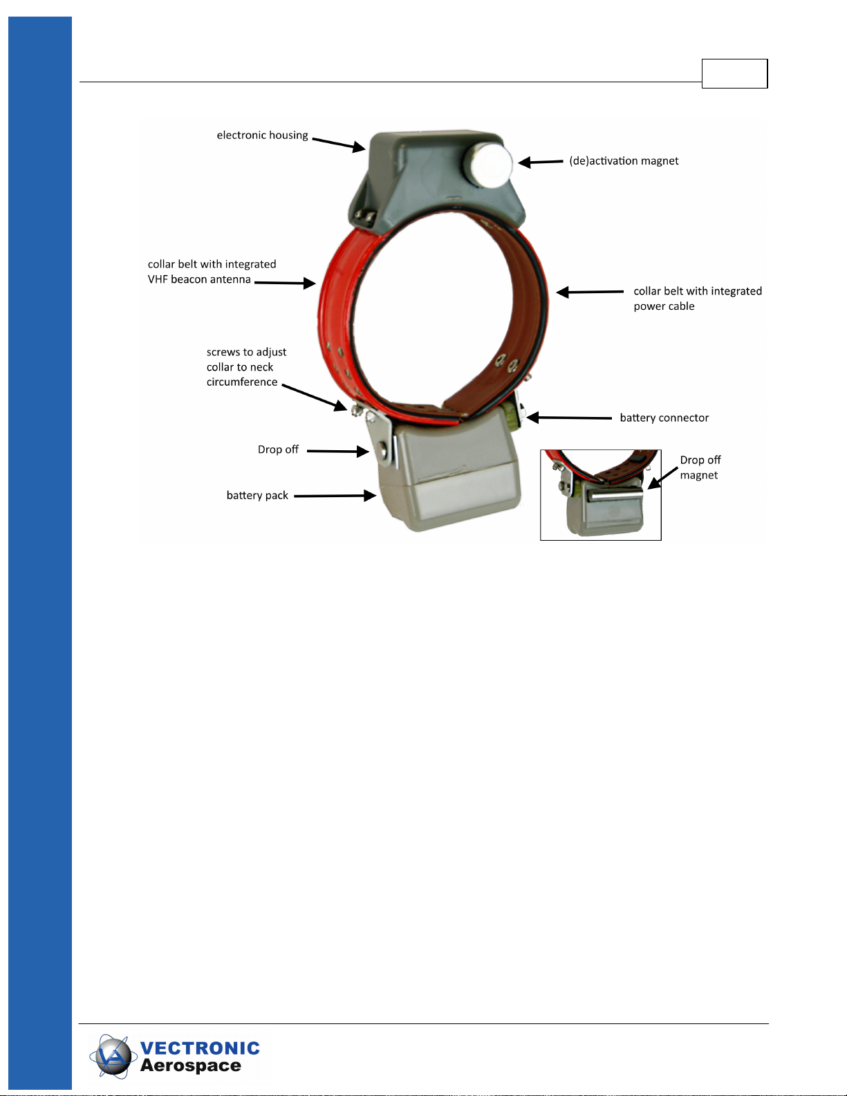
The VERTEX Lite Collar uses a two housing design, one electronic and one battery unit.
The VHF beacon antenna is integrated into the belt. There are different collar designs,
housings and battery sizes to fit it to each species.
Fast guide to deploy the collar 9
follow the links to the subtopics explaining the collar and its system:
The collar
GPS Receiver
VHF Beacon
Mortality Sensor
Communication options
Software
Data Format
3.1 The Collar
The VERTEX Lite Collar consists of the following components:
© 2017 VECTRONIC Aerospace GmbH
The Vertex Lite collar system 10
3.2 GPS Receiver
The collar contains a standard GPS receiver with an accuracy within 8 - 15 meters as
mean. The actual accuracy depends on many factors such as terrain, satellite reception
and time to conduct a fix (GPS position). Most fixes will be far more accurate.
A GPS schedule defines when GPS positions will be recorded. Programming of the
GPS schedule is very flexible and easy.
Once activated the receiver listens for satellite data and collects ephemerides data to
conduct a GPS location. The maximum listening period is 180s but it will stop listening
before that if
a) it receives a validated fix of highest quality
b) it gets several decent quality signals
c) it gets no satellite connection at all
Figure 1: VERTEX Lite Collar
Each GPS position is stored with following data:
© 2017 VECTRONIC Aerospace GmbH
- UTC (universal time coordinated) date and time
- GPS coordinates (Latitude, Longitude and Height)
- Dilution of Precision (DOP) and navigation status as quality information as well as
number of satellites used for positioning.
GPS data can be exported via the user software GPS Plus X to ASCII, Spreadsheet,
DBase, GPS Exchange, Google Earth and BioTelemetry eXchange format. You can
easily import the data into Google Earth via kml.file to visualise GPS positions.
3.3 VHF Beacon
The collar is equipped with a powerful VHF beacon. The VHF Beacon transmits a signal
on Very High Frequency. It allows you to track the collar even if satellite or GSM
communication is down. The VHF Beacon is set for a certain range of frequencies and
you are able to change it within this range using GPS Plus X. You can program when the
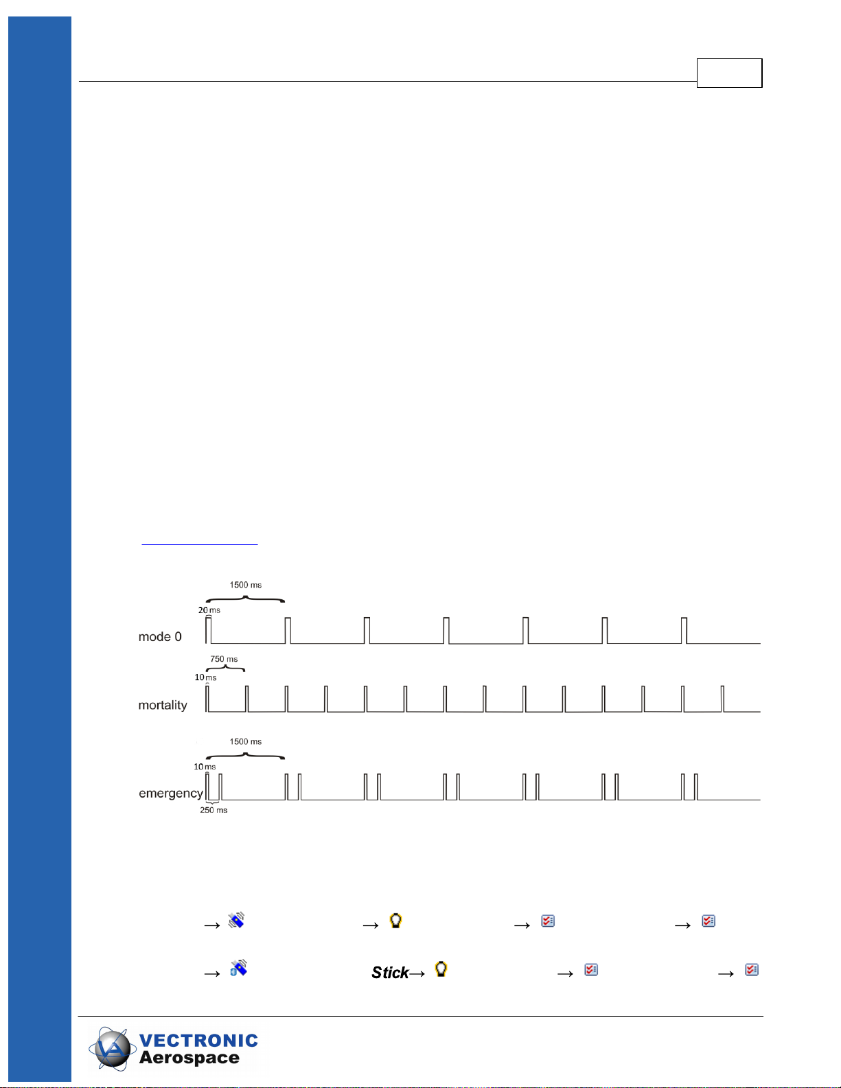
VHF Beacon is on and also its signal pattern. The VERTEX Lite has three distinct signal
modes, the Standard Pattern the Mortality Pattern and the Emergency Pattern. There is
a backup battery for the beacon to ensure you do not loose your collar due to low battery
issues. The Mortality Pattern is active when a mortality event has been recorded
(Mortality Sensor). The default setting can be seen below but you are able to change the
Pulse Length and also Loop Length meaning the cycle in which the signal is repeated.
The Vertex Lite collar system 11
Figure 2: Beacon patterns (default setting): Standard Pattern, Mortality Pattern, Emergency
Pattern
The changes can be made in the GPS Plus X software:
Devices Remote Stick VERTEX Lite Configuration User
Configuration
Devices USB Bluetooth VERTEX Lite Configuration
© 2017 VECTRONIC Aerospace GmbH
User Configuration
3.4 Mortality Sensor
The mortality sensor measures the activity of the animal. If no movement (activity) is
detected for a user-defined period (e.g. 24 hours), a mortality event is triggered. The
mortality period is user-definable and can be set up to 140 hours. When a mortality
event is detected, the collar:
- Switches the VHF Beacon pattern to the Mortality Mode
- Sends out a mortality event message via Globalstar / Iridium / GSM
communication
- Conducts unscheduled GPS fixes each 30 minutes for six hours before it returns
to the programmed schedule
- Sends messages according to set communication patterns
The Vertex Lite collar system 12
The collar will end the mortality mode if the sensor registers repetitive activity for roughly
20 minutes.
NOTE: The mortality period should be adapted to the behavior of the collared animal so
you get no false events (e.g. lions with a very long passive phase should get a longer
mortality period as for example roe deer with a distinct but short activity pattern). The
default setting is 24h which has been used successfully in a variety of studies.
3.5 Activity Sensor (Acceleration)
The VERTEX Lite Collar is equipped with a Basic Activity sensor. The data are stored
in the on board flash memory. The sensor records average data every 300 seconds.
You can analyze relative activity based on right-left, up-down and forward- backward
movement.
© 2017 VECTRONIC Aerospace GmbH

3.6 Drop Off
The Vertex Lite collar system 13
Figure 3: Directions of the three activity axes
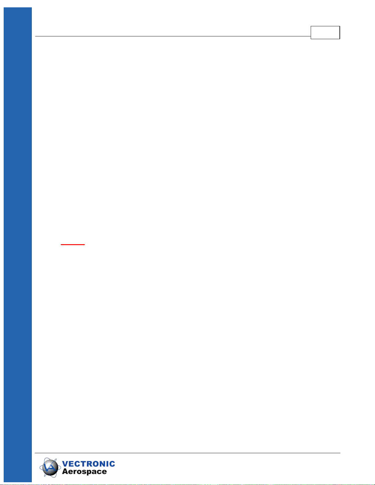
Drop Offs allow retrieving the collar without having to recapture the animal.
There are two optional Drop Offs available:
- Timer-controlled Drop Off: The collar is released after a pre-defined period of time
(relative mode, e.g. 100 weeks) or at a pre-defined date and time (absolute mode, e.g.
01 April 2017). The lifetime of the Drop Off is up to five years after production. The
countdown in relative mode starts after removing the Drop Off magnet.
- Radio-and-timer-controlled Drop Off: The collar is released on demand by UHF
radio signal. For the release an UHF Handheld Terminal Version 5 or higher or a Drop
Off Release Transmitter is needed. The maximum distance is about 500 m (For more
information please refer to the Drop Off Release Transmitter manual). Additional timer
control (relative or absolute mode) functions as backup. The lifetime of this Drop Off is
up to 4 years after production.
Figure 4: Drop Off magnet for standby mode
© 2017 VECTRONIC Aerospace GmbH
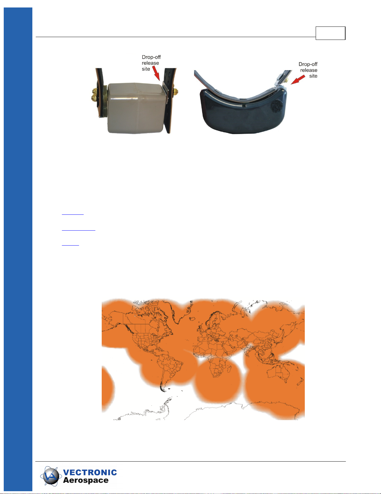
Figure 5: Drop Off release sites, magnet removed
3.7 Communication options
The VERTEX Lite Collar is available as Iridium, Globalstar or GSM version. Follow the
link to your chosen configuration for information about the respective communication
system.
Iridium
The Vertex Lite collar system 14
Globalstar
GSM
3.7.1 Globalstar Communication
Globalstar offers a one-way communication means you receive GPS and mortality data,
transmitted by the collar. The system provides a broad but space and time restricted
coverage network.
Figure 6: Globalstar Coverage 2015
© 2017 VECTRONIC Aerospace GmbH

The Vertex Lite collar system 15
Each position data is sent by the collar (1-2 Fix per message with minimum pause of
30min between each message). Data is send out several times to increase
transmission probability but data reception is not confirmed by the satellites. The
satellite sends its data to a base station on ground which forwards it via web to our
system. It is possible that transmissions are blocked (e.g. thick canopy, bad angle
towards ski etc.) and do not reach the satellites and thereby you. Most often the data will
get through and to our system from which your GPS Plus X software will automatically
download the data. You can also get the data as email forwarding when the Http
download is unsuitable for whatever reason. You can get the full dataset by downloading
it after collar retrieving with the USB Remote stick.
NOTE: You can set a skip count to exclude some fixes from the data satellite
transmission pool to receive fewer messages and thereby extend the collar lifetime (e.g.
skip count 2 means sending only every second fix, all data remains stored on the collar
too). Please keep in mind that you cannot alter the settings once the collar is deployed.
A skip count could potentially drastically reduce the collar messages you receive up to
getting no data (e.g. high GPS skip count in a very unsuitable habitat such as dense
forest). For further information please contact our customer service.
3.7.2 Iridium Communication
Iridium offers a two-way communication means you receive GPS data from the collar
and can send new commands and schedules remotely to the collar. The Iridium system
contains of 66 satellites with global coverage for 24 hours per day.
Figure 7: Iridium 24h worldwide satellite coverage
You can download and upload schedules and configurations remotely. Due to the twoway communication, the collar knows which data have been received by the satellite and
which data need to be resent again. That means you will get all data even so it can
happen that some data packages come in later.
For transmitting the data the collar needs clear view to the sky. The number of fixes
defines the message size and thereby transmission time.
© 2017 VECTRONIC Aerospace GmbH

The Vertex Lite collar system 16
How it works:
The system uses 3 message blocks whereas the first block can contain 1-4 GPS fixes,
the second block additional 8 at most and the third and last block additional 6. In total,
18 fixes (in one big message) can be transmitted in one transmission window. The
remaining space within a block will be filled with placeholder data, so the message won't
get smaller if you choose less than 4 (1-3), 12 (5-11), 18 (13-17).
Please note that the collar “listens” for incoming commands whenever it has send out
data only, meaning you have distinct communication windows based on the schedule
used and transmission made (e.g. hourly fixes with 4 fixes a message result in one
message every 4 hours). Data are sent to our GPS Plus X main server and provided to
your GPS Plus X software for HTTP download or email forwarding / reception.
NOTE: It highly depends on species and terrain how many fixes the collar should
transmit in one message. In most cases we recommend to start with 4 fixes per
message (default settings) and to increase the number after deployment when you see
data is incoming regularly. An unsuitable setting (e.g. 18 fixes / message in dense
forest) could result in high rate of failed transmissions or in worst case in loosing contact
to the collar.
NOTE: You can set a skip count to exclude some fixes from the data satellite
transmission pool to receive fewer messages and thereby extend the battery lifetime
(e.g. skip count 2 means sending only every third fix, all data will be stored in the collar
too). A skip count reduces the collar messages you receive (High GPS skip count in a
very unsuitable habitat such as dense forest may result in loosing contact with the collar).
3.7.3 GSM Communication
GSM is using the SMS service of mobile phone providers. The GSM communication is
a two-way communication, means you receive GPS data from the collar and can send
new commands and schedules remotely to the collar. GPS and mortality data will be
sent automatically via SMS to the defined phone number. If you wish sending new
commands or schedules remotely, please contact our customer service. It is only
possible to communicate with the collar within GSM provider coverage.
© 2017 VECTRONIC Aerospace GmbH

The Vertex Lite collar system 17
Figure 8: GSM Communication
For collar usage within Europe we provide GSM collars with VECTRONIC SIM chips
so you do not have to take care about provider administration. VECTRONIC SIM chips
are soldered in the electronic housing and highly reliable in all kinds of environmental
conditions (heat, cold, humidity, vibrations, shock).
How it works:
One message transmitted via GSM/GPRS contains 8 GPS positions per default.
Messages will be send to VECTRONIC ground-station and from there downloaded via
HTTP to GPS Plus X software. All GPS Data, irrespective of transmitting, will be stored
in the non-volatile on-board-memory. Data not transmitted via GSM can be downloaded
via UHF radio link (if available) or via USB Remote Stick after the collar has been
retrieved.
For collar usage in Africa, Asia or Nord- and South America you may choose your own
mobile phone provider and provide Micro SIM cards on your own. Here, message
transmitted via GSM contains 7 GPS positions per default. It is recommended having
your own GSM Ground station if you using your GSM collars with your own SIM cards.
© 2017 VECTRONIC Aerospace GmbH

The Vertex Lite collar system 18
Figure 9: GSM Ground Station
NOTE: If no communication can be established between the GSM network and the
collar or the GSM ground station, the GSM provider will retry to send the data. Data in
the provider's memory are subject to a validity period. If no contact has been
established within this period (usually 2-3 days, but depending on the provider's
conditions), the data stored by the provider will be deleted without delivery. For this
reason make sure that your ground station is switched on at all times to allow the data to
reach you within the validity period. If a newly send GPS schedule is not delivered within
the validity period, resend the schedule to make sure that the collar has received the
new schedule from the GSM network. If you have questions please do not hesitate to
ask our customer service.
3.8 Software
All VECTRONIC collars are managed with our free software GPS Plus X which can be
downloaded from our homepage (www.vectronic-aerospace.com). It is also on the user-
CD which accompanied the collars in the first place.
The auto-installer includes an Installation Wizard which will guide you through the
installation and setup.
For more information refer to System Set-up.
3.9 Data Format
All data is stored internally in binary format and can be exported as ASCII, Spreadsheet,
DBase, and BioTelemetry eXchange format. GPS data can also be exported as GPS
Exchange and Google Earth files.
- GPS position information: No, Collar ID, UTC date and time, LMT date and
time, origin, SCTS date and time, ECEF X,Y and Z, latitude/longitude/height,
DOP, 3D Error, number of the used satellites, Satellite ID (Sat No), Carrier to
Noise (C/No [dBHz]), battery voltage, mortality status, temperature and activity
- Temperature: Temperature data are stored and transmitted with the GPS
position data.
© 2017 VECTRONIC Aerospace GmbH

- Mortality information: Date and time of a mortality event based on the activity
.GDF
GPS Data File
Binary coded GPS fix data from the collar including
main battery voltage, VHF beacon battery voltage, and
temperature. The file name consists of the collar
number and the time stamp of the file creation coded
as “yyyymmddhhmmss”.
.GDF
GPS Data File
Binary coded GPS fix data from the collar including
main battery voltage, VHF beacon battery voltage, and
temperature. The file name consists of the collar
number and the time stamp of the file creation coded
as “yyyymmddhhmmss”.
.TXT
ASCII
Visually readable equidistant table, compatible to conventional text editors and spreadsheets
.CSV
Spreadsheet
Computer readable table, compatible to conventional
text editors and spreadsheets
.DBF
DBase Table
Database format, compatible to conventional spreadsheets and most text editors
.GPX
GPS Exchange
Format
File for data exchange with GPS devices
.KML
KML
Google Earth file to display tracks, points of interest…
.KMZ
KMZ
Zipped Google Earth file
of the animal. The GPS Plus X software stores the received mortality message in
the data base.
- Activity: records averaged data every 300 seconds on 3-axis (X, Y, Z). So,
you can analyze relative activity based on right- left, up- down and forwardbackward movement. Activity data can be downloaded after collar retrieving.
(Format: adf. or adf3.)
3.9.1 List of files and extensions used
Download files
The Vertex Lite collar system 19
Export files
© 2017 VECTRONIC Aerospace GmbH

.BTX
BioTelemetry
eXchange
VECTRONIC-defined XML-format
.GDX
.ADF
.ADF3
GPS Data eXchange
Is an XML format defined by VECTRONIC Aerospace,
which will make it easier to exchange acquired data
over system boundaries. It is an internal format of GPS
Plus X and can also be used as import format.
2-axis Activity Data File
3-axis Activity Data File
Upload files
.vbsf
Beacon Schedule File
VHF beacon schedule of the Survey collar
.vgsf
GPS Schedule File
GPS schedule of the Survey collar
.CCF
Collar Configuration
File
contains the configuration (schedules, communication
configuration, activity mode) of the collar
.bin
Collar Firmware File
contains firmware for Survey collars
.key
Collar Key File
contains a key for one collar, needed to register the
collar in the GPS Plus X and to manage its data
.txt
Collar Info File
contains all information on the collar configuration
The Vertex Lite collar system 20
Hardware information files
4 System Set-up
All VECTRONIC collars come completely programmed according to your specifications.
You can change the configuration yourself with the GPS Plus X user software and the
Communication Device (USB remote Stick, USB Bluetooth Stick).
This section will guide you through all steps for getting started whereas you will
find a more detailed description for all features in the GPS Plus X software Manual.
© 2017 VECTRONIC Aerospace GmbH

Firstly: Installation of the user-software GPS Plus X
Secondly: Collar Registration
Thirdly: Registration of the Communcation Device (USB Remote Stick / USB Bluetooth
Stick)
4.1 Installation of the user-software GPS Plus X
The Installation wizard will guide you through the process of installing GPS Plus X. You
can install the software from the User-CD (auto-run or manual from the folder / software /
GPS Plus X) or download the latest version from our website: www.vectronic-
aerospace.com.
The installation procedure will ask you for a destination directory and suggest a default
directory. You can now decide whether you want to install one of the following software
packages (list might vary with program versions):
User Interface: Collar communication and configuration
Data Storage Service: Data management, visualization and export
Data Collector Service: Data reception and distribution
Color Selector: Tool to select a color for the belt of your collar
TeamViewerQS VAS: Tool for remote desktop support
GPS Plus X Manual: integrated Manual
System Set-up 21
By default, GPS Plus X will be configured to run on a single computer. Please refer to
the GPS Plus X software manual for further details on GPS Plus X network set-up.
4.2 Collar Registration
To be able to configure the collars and to process data and messages with the GPS Plus
X software, you need to register the collars. The keys for each collar will be provided with
the User-CD which came with the collars in the first place.
For registering the collar, please go to the Configuration tree in GPS Plus X and
select Collars
© 2017 VECTRONIC Aerospace GmbH

System Set-up 22
Figure 10: Collar Properties Editor
In the appearing window “Collar List”, press to add a new collar to the list. After
clicking on the button, the Collar Properties Editor appears. To register a collar, click
. An open file dialog will open and you can select the collar registration key for
the collar (to be found in the folder Resources\Collar and Drop Off Keys).
If you add the details before registering the collar, the registration status of the collar will
be invalid. After registration, the entry of the corresponding collar will change from invalid
to valid. For more information on collar registration, refer to the GPS Plus X Manual.
After you have registered the collar, you will be able to communicate with the collar using
the USB Device.
4.3 Registration of Communication Devices
To be able to configure the collars and to process data and messages with the GPS
Plus X software, please connect either the USB Remote Stick or the USB Bluetooth
© 2017 VECTRONIC Aerospace GmbH

System Set-up 23
Stick to your PC while GPS Plus X is open. When you plug in the USB Device for the
first time, you need to register it. A window will appear to inform you that this device has
not been registered yet (see Figure below). It will give you a Device Description and the
possibility to choose a Display Name.
Figure 11: USB Remote Stick registration
Click on after you have typed in a name which allows you to recognize your
USB Device easily.
After you have registered the USB Device, it will appear in Configuration Local
Settings Device Registration.
USB Remote Stick:
Clicking on the Remote Stick symbol in the Devices tree, the USB Remote Stick
Properties frame will open.
© 2017 VECTRONIC Aerospace GmbH

System Set-up 24
Figure 12: USB Remote Stick Properties
In this frame, you can see all the details of the Remote Stick, change the Display Name
and upload the new firmware by clicking on in the Firmware Upload tab (if a
newer version than the recent one is available).
If you registered collar and Remote Stick you can start managing your collar.
NOTE: The Driver of the Remote Stick should be automatically found. If the installation
does not work automatically you can find the driver (as executable) on the User-CD,
folder Resources/VECTRONIC Tools and Drivers/USB Driver installer/ USB To Collar
Interface Driver Setup.exe)
© 2017 VECTRONIC Aerospace GmbH

System Set-up 25
USB Bluetooth Stick:
If the Bluetooth Stick does not show up, refer to USB Bluetooth Stick for information
about driver setup.
If you click on the USB Bluetooth Stick itself the property frame will open. Here you
can rename your device or upload the latest firmware version.
Figure 13: USB Bluetooth Stick Properties
© 2017 VECTRONIC Aerospace GmbH

5 Direct Collar Communication
VERTEX Lite Collars can be accessed via USB Remote Stick or via USB Bluetooth
Stick.
Figure 14: left: USB Remote Stick; right: USB Bluetooth Stick
Combined with the GPS Plus X software, these are tools to upload configurations,
schedules and to download measurement data or show collar status information. You
need to make the configurations while one of the USB devices is attached to your
computer and the collar is in a range of a few meters. You are able to communicate with
several collars simultaneously and configure them parallel as well.
Direct Collar Communication 26
After you set-up your system you are able to communicate with the collar.
5.1 USB Bluetooth Stick
If you update your GPS Plus X software, the following frame will appear. Click install to
be able to use the USB Bluetooth Stick.
Figure 15: USB Bluetooth Stick Driver installation
© 2017 VECTRONIC Aerospace GmbH

Direct Collar Communication 27
You can find the USB Bluetooth Stick under Devices USB Bluetooth Stick. If
you remove the magnet of your VERTEX Lite collar it will appear as a subnode of the
Bluetooth Stick. Now you can change Collar Configurations and Schedules and access
Information and Collar Data. Refer to Collar Main Tree for more information.
5.2 USB Remote Stick
You can find the USB Remote Stick under Devices Remote Stick. It shows two
options ( Radio Monitor and Device Search) whereas only the latter is important
for the first steps in collar communication.
Figure 17: USB Remote Stick Device Search frame
Figure 16: Device list: USB Bluetooth Stick
© 2017 VECTRONIC Aerospace GmbH

Direct Collar Communication 28
The “Radio Monitor” feature is discussed in chapter The VERTEX Lite Collar as UHF ID
Tag.
In the node “Device Search” you can search for collars. Per default you search for any
devices in range (“Any Device”). You can also search for specific device types. To do
that, select a Device Type. If you want to search for a specific collar ID, please enable
Specific Device ID and select the ID of your collar. Click on , attach the
magnet to your device within the next 10 seconds and detach it after one second (As it
is described in Collar Contact (general)). A list of all devices found will appear.
Figure 18: USB Remote Stick Device Search frame
Once ensured that the devices work and can be contacted by the software, collar
communication and reconfiguration can be started.
5.2.1 Remote Stick Collar Contact
To configure the collar, make sure that the magnet is detached from the collar so that it
is able to receive configurations and send data. Whenever you click on a node in the
Devices tree (Information, Configuration, Schedules or Collected data), a notification
message will appear. In this message, you are requested to attach the magnet to the
collar and detach it after one second. You can abort the connecting process by clicking
the corresponding button or the ESC button on your keyboard.
Figure 19: Notification window which appears when you send out a command of any kind.
© 2017 VECTRONIC Aerospace GmbH

It happens that the communication cannot be established showing different error
messages. Most often it will be enough to redo it. The communication works best when
there is a clear path between collar and USB Remote Stick without obstacles which
might interfere with the signals.
Recommendation: A simply trick to further fasten the process is to place the magnet
upside-down on the connection port of the collar while working with it instead of
reattaching it securely with the Velcro tape each time.
5.2.2 Testing several collars
Most features offer you the option to read out / upload a schedule / parameter /
configuration to a specific collar or any collars in range. Using the latter option you can
check and reconfigure your collars in a row without much in-between handiwork
involved. Please note that it works for collars of one kind only.
Direct Collar Communication 29
Using the “Any Collar” option the command is internally (invisibly) altered so it can be
received and processed by any fitting collar (e.g. no collar ID involved). You will have to
press “apply”, “send” for each collar anew but do not have to move within the
configuration tree.
5.3 Collar Main Tree
Devices Remote Stick VERTEX Lite
Devices USB Bluetooth Stick VERTEX Lite
The Collar Main Tree gives you an overview on what can be down- and uploaded to and
from your collar and informs you about current settings.
Figure 20: Command destination
© 2017 VECTRONIC Aerospace GmbH

Direct Collar Communication 30
The first node (Information) contains what it says, information about hardware and the
actual settings of the collar. It also enables testing its basic functionality.
The second node (Configuration) includes all user configurations for the collar and is,
with the third node (Schedules) where you can define and upload VHF and GPS
schedules, the most important one.
The fourth node (Collected Data) gives you the option to download data once you
retrieve the collar after its deployment.
5.3.1 Information
Devices Remote Stick VERTEX Lite Information
Devices USB Bluetooth Stick VERTEX Lite Information
Shows the actual hardware and programming settings of the collar and its functionality.
Figure 21: Collar Main Tree (VERTEX Lite)
© 2017 VECTRONIC Aerospace GmbH

Telemetry
GPS Monitor
Info File
5.3.1.1 Telemetry
Devices Remote Stick VERTEX Lite Information Telemetry
Devices USB Bluetooth Stick VERTEX Lite Information
Telemetry
The Telemetry window gives an overview about all hardware and software settings of the
collar. It shows the actual programming with no option to change it here. That is done (as
far as the options can be altered) in the node Configuration
Direct Collar Communication 31
© 2017 VECTRONIC Aerospace GmbH

Direct Collar Communication 32
Figure 22: Collar Telemetry
System:
Collar shows Production Number, Production Date, Printed Circuit
© 2017 VECTRONIC Aerospace GmbH

Direct Collar Communication 33
Board (PCB) Type and Collar ID.
Time shows the collar time in UTC and the UTC correction set for the
collar
Firmware shows information about the collar software: Bootloader and
Firmware information. Internal or service related information only
Internal Sensors shows the Main Voltage and the ambient temperature of the
included mortality sensor. The voltage is an important value to
estimate collar status as described in Position
Bluetooth Module:
Firmware Version shows Firmware Version of the Bluetooth Module in the collar
Firmware Date shows the date of the Bluetooth Module Firmware
Serial Number shows Serial Number of Bluetooth module
Memory:
External Flash Erase Time
shows time when external flash memory gets erased
Reset Counter: Internal use only (debug)
IRQ Counter: Internal use only (debug)
Link Registers: Internal use only (debug)
Sensors:
GPS shows information about the GPS Mode (internal usage only),
GPS Max Fix Time in seconds, GPS Fix Count (number of fixes
collected so far) and the GPS skip Count. The latter meaning to
put only selected fixes into the transmission data (e.g. every
second fix) and leave the rest for USB wireless data download
only.
Acceleration shows acceleration mode (basic)
Mortality shows the Period of the mortality sensor: the Default Period
which was set by VECTRONIC Aerospace and the User Period
which is user definable
Activity Activity Data Page Counter: counter to save activity data value
(in pages)
Communication:
Radio shows information about the Transmit Frequency, Receive
Frequency and Transmit Power of the collar
© 2017 VECTRONIC Aerospace GmbH

Direct Collar Communication 34
Globalstar shows the Globalstar Mode, the amount of Globalstar attempts
and the ESN number
Iridium shows the Fixes per Message (user-definable) and IMEI number
of the collar (potentially needed in collar registration)
GSM mode, destination number, and the reception delay which
defines the delay until the GSM modem starts to send data
Beacon:
Beacon Frequency shows the frequency of the VHF beacon: the Default Frequency
which was set by VECTRONIC Aerospace and the User defined
Frequency. Furthermore, the values of the Beacon Min
Frequency and the Beacon Max Frequency are shown which
define in what range you are able to alter the VHF frequency
Beacon Power shows the VHF Beacon output Power.
Patterns shows information about the Standard Pattern as well as the
Sensor Communication:
Repetition Interval defines how often the collar transmits its UHF ID
Proximity Transmitter shows if its on / off, transmit frequency, and transmit power
5.3.1.2 GPS Monitor
Devices Remote Stick VERTEX Lite Information GPS
Monitor
Devices USB Bluetooth Stick VERTEX Lite Information
GPS Monitor
Mortality Pattern and the Low Battery Pattern of the VHF
beacon. The patterns include the Default Pattern which was set
by VECTRONIC Aerospace and the User Pattern if it is
configured. For the Low Battery Pattern you can define 'Start
Time', 'Cycle Period' and 'On Duration'.
The GPS monitor function allows to check the GPS receiver. There are two options in
this frame, GPS Warmstart and a GPS Coldstart. Both commands should only be used
for diagnostics and outside of buildings with open view to the sky.
© 2017 VECTRONIC Aerospace GmbH

Direct Collar Communication 35
GPS Warmstart: This button will initiate a Warmstart of the collar. The GPS receiver
will use the Ephemerides and other data already stored in the collar (flash memory,
remains there for roughly 2hours) and only complete them with actual satellite data.
Depending on what is already stored, it can be fast or take some time. You can abort
the Warmstart by changing the node.
GPS Coldstart: The command is quite similar to the GPS Warmstart command. The
GPS receiver will skip its potentially stored ephemerides and download every available
data from the GPS satellites anew. It will take much longer to acquire a GPS location.
A GPS Coldstart is necessary if you changed the battery pack of your collar or if the
collar was inactive for a few weeks / months.
5.3.1.3 Info File
Devices Remote Stick VERTEX Lite Information Info File
Devices USB Bluetooth Stick VERTEX Lite Information
Info File
The collar info file includes all information on the collar configuration. It can be saved as
.TXT file or printed directly. It contains technical information of the collar as well as the
schedules. For the GPS as well as for the VHF beacon you can see the Default
Schedule and the User Defined Schedule. For the GPS as well as for the VHF beacon,
Figure 23: VERTEX Lite GPS Monitor after fix has been obtained
© 2017 VECTRONIC Aerospace GmbH

Direct Collar Communication 36
you can see which schedule is used at the moment (in the example it is the User
Defined Schedule). Every schedule is shown in a version which can be easily read and
in the .XML format which is machine readable. An example of an Info File of the
VERTEX Lite is given in in the following table.
Recommendation: Create and save a new Info-Sheet whenever you have the collar at
hand and did any changes, especially before deployments.
© 2017 VECTRONIC Aerospace GmbH

Direct Collar Communication 37
Figure 24: VERTEX Lite Iridium Info File
© 2017 VECTRONIC Aerospace GmbH

5.3.2 Configuration
Devices Remote Stick VERTEX Lite Configuration
Devices USB Bluetooth Stick VERTEX Lite Configuration
In the Configuration node you can change all user-definable configurations of your collar.
Direct Collar Communication 38
Please refer to following subtopics of the Configuration Node:
User Configuration
Setting the time
Firmware Upload
5.3.2.1 User Configuration
Devices Remote Stick VERTEX Lite Configuration User
Configuration
Devices USB Bluetooth Stick VERTEX Lite Configuration
User Configuration
In this frame you can change the user-definable configurations. The actual configurations
can be seen in the collar's Telemetry and Info File. Faulty entries (e.g. faulty UTC
correction) will automatically be reset back to the factory settings defined by
VECTRONIC Aerospace.
Figure 25: Configuration node
When configuring different settings, a small window will appear whenever marking a
parameter you like to change. In this window, you will get the information which values
you can put there (Min value and Max value). This window appears in the User
© 2017 VECTRONIC Aerospace GmbH

Direct Collar Communication 39
Configuration frame for every value you can configure.
Figure 26: Window with Min and Max value for the Beacon Frequency
You can define the following parameters:
System
UTC correction the collars use the UTC (Universal Time Coordinated) time
which is also used by the GPS satellite system. It differs to
your LMT (Local Mean Time). To give an example: LMT in
Germany is +2 hours to UTC, UTC correction: +2 hours. You
can set the UTC Correction in GPS Plus X and the collar will
then translate your in LMT programmed schedule internally.
Recommendation: stick to either way (UTC correction or
UTC schedules) for all collars and document it carefully. It
easily happens to get confused especially if you ask us to
do some changes.
Sensors
GPS Skip Count The GPS skip count refers to the satellite communication
enabling you to set a number of GPS location which will be
conducted and stored but are not added to the transmission
pool. (Example: a Globalstar collar with 2 fixes a day and
skip count 1, will send only one data message with 1
location per day).
Mortality Period Here you can set a time span using the up- and down
arrows. If the activity values remain under the set threshold
(64 within a 0-255 range, changeable by VECTRONIC) for
this time span, the animal is assumed to be dead and a
mortality event is triggered. The default value is 24h with
have been successfully used in many studies.
NOTE: Please consider which values might reflect animal
behavior at best. A short period might lead to false alarms
as the animal is only resting.
© 2017 VECTRONIC Aerospace GmbH
Direct Collar Communication 40
Communication
Iridium The Iridium Mode (1-18) defines the number of fixes per
Iridium message. Please check Iridium Communication for
information about message set-up and size.
Recommendation: Mode 4
Globalstar Choose one out of 3 modes: [0] Disabled, [1] 1 Position per
Message, [2] 2 Positions per Message
GSM The GSM Mode defines number of fixes per SMS.
Recommendation: 8 fixes per message with VAS SIM
chips
7 fixes per message with SIM cards
from your own provider
You can change the destination address of all incoming
messages. By default it will be the number of VECTRONIC
ground station. If you are using your own ground station your
own mobile number is setup here.
You can configure the Reception Delay which depends on
the providers delay. The GSM module in the collar will
booked in the network for additional time to receive
messages.
Beacon
Beacon Frequency Choose the frequency of your VHF beacon by simply typing
it into the field. You can only select frequency values
between the minimum and maximum value.
NOTE: Signal strength is best with the primarily set value
(hardware dependent), signal strength will slightly decrease
at the rim.
Beacon Power Recommendation: Stick to the default value of 10dBm as
it offers the optimum balance between signal strength and
energy consumption. Please contact our customer service if
you have questions.
© 2017 VECTRONIC Aerospace GmbH

Direct Collar Communication 41
Beacon Mortality Mode This defines if at a mortality event the VHF should switch to
be always on (24/7) or remain schedule controlled (e.g.
short window only). The Default setting is: Always on
Beacon Patterns In this frame you can configure the VHF beacon pattern for
both the Standard and Mortality Mode active during a
mortality event. You can set the pulse length in milliseconds
(ms) and the Loop Length in ms. The “pulse Type” is for
internal usage only and can’t be changed by the user.
NOTE: The default settings have been successfully used in
many studies. Changes will effect battery consumption.
Figure 27: VERTEX Lite User Configuration
© 2017 VECTRONIC Aerospace GmbH
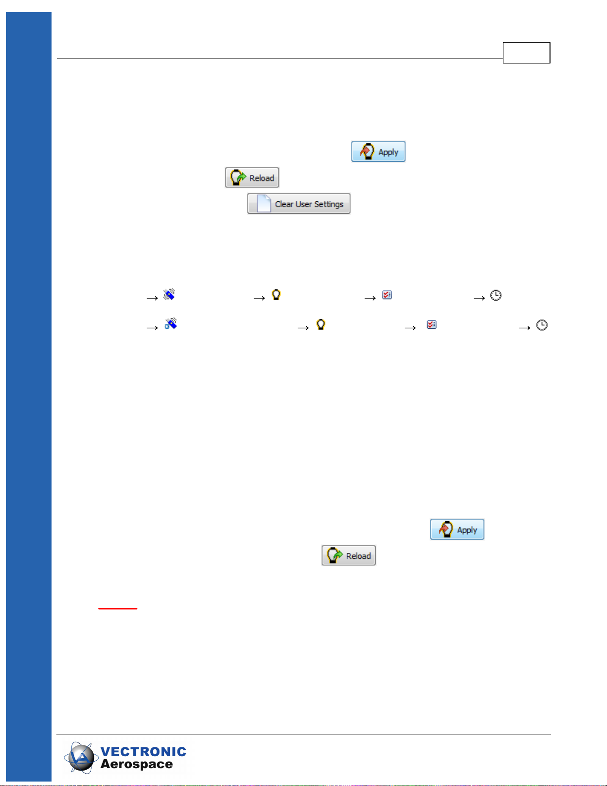
After you have provided your changes in the configuration, you can choose if you like to
send the new configuration only to the selected collar or to any collar by setting up the
Destination on the left side of the frame. Press to send the settings to the
specific collars. Press to reload the configuration from the actual chosen
collar. Pressing the button , all settings in the collar except the
schedules are deleted. Afterwards, the default settings defined by VECTRONIC
Aerospace are applied.
5.3.2.2 Setting the time
Devices Remote Stick VERTEX Lite Configuration Time
Devices USB Bluetooth Stick VERTEX Lite Configuration
Time
Direct Collar Communication 42
To set the time in the collar, make sure that the USB Device is attached to your PC, click
on the Time frame in the Configuration node, attach the magnet to your collar within 10
seconds and detach the magnet from the collar.
Two times are displayed, the Current Collar Time [UTC] and the PC Time. The frame
also displays the Computer UTC Correction. The New Collar Time [UTC] is by default
given as the PC Time calculated from the PC UTC correction and the PC’s current time.
If there are differences between PC time and the time you want to set in the collar, use
the up- and down arrows and the calendar function or type in the new time. After you
have provided your changes in the time, you can choose if you like to send the new
configuration only to the selected collar or to all collars found in the Device Search by
setting up the Destination on the left side of the frame. Press to send the
new time to the collar / to the collars. With you can reload the configuration
from the collar.
NOTE: With each successful GPS fix, the collar time is automatically adjusted to the
correct UTC time. UTC correction will be only applied for schedules and time of the day
settings. Also, UTC correction cannot be enabled by sending the local mean time to the
collar.
© 2017 VECTRONIC Aerospace GmbH

Direct Collar Communication 43
Figure 28: Set Time Frame
5.3.2.3 Firmware Upload
Devices Remote Stick VERTEX Lite Configuration
Firmware Upload
Devices USB Bluetooth Stick VERTEX Lite Configuration
Firmware Upload
A Firmware update is only necessary if you experience problems with the current collar
firmware or need a feature only available in a newer version than the present one. In this
case, get the appropriate file from VECTRONIC Aerospace. Select the update (.bin) file
with . Afterwards, you can see that some information appears in the window. You
can check information on Device Model, File Type, Version (the firmware version you
are going to upload to the collar) and the Version Attributes. Send the upgrade to the
collar with . The upload will be verified automatically while it is progressing.
© 2017 VECTRONIC Aerospace GmbH

5.3.3 Schedules
Devices Remote Stick VERTEX Lite Schedules
Direct Collar Communication 44
Figure 29: Collar Firmware Upload frame
Devices USB Bluetooth Stick VERTEX Lite Schedules
Schedules, either VHF or GPS, define when the respective sensor is on, meaning the
VHF Beacon is broadcasting and the GPS receiver is conducting GPS fixes. Both
require battery power and some serious thoughts should be spend on before
deployment.
Figure 30: Schedule creation window
The schedule creation window shows all option around collar creation and is more or
less identical for the GPS as well as the VHF schedule builder. They differ in the rule
format which are described in the following chapters.
© 2017 VECTRONIC Aerospace GmbH
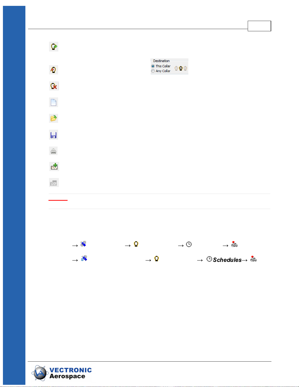
Direct Collar Communication 45
Load schedule from collar (either GPS and VHF schedule)
Upload created schedule to collars ( )
Erases the collar schedule
Clears the tool window to start schedule builder anew
Loads a previously saved schedule
Saves a created schedule for later usage and control
Prints out the listed rules
Schedule builder tool: add a new rule
Schedule builder tool: delete selected rule
NOTE: Please keep in mind that the VERTEX Lite Globalstar collars can’t be
reconfigured remotely once deployed.
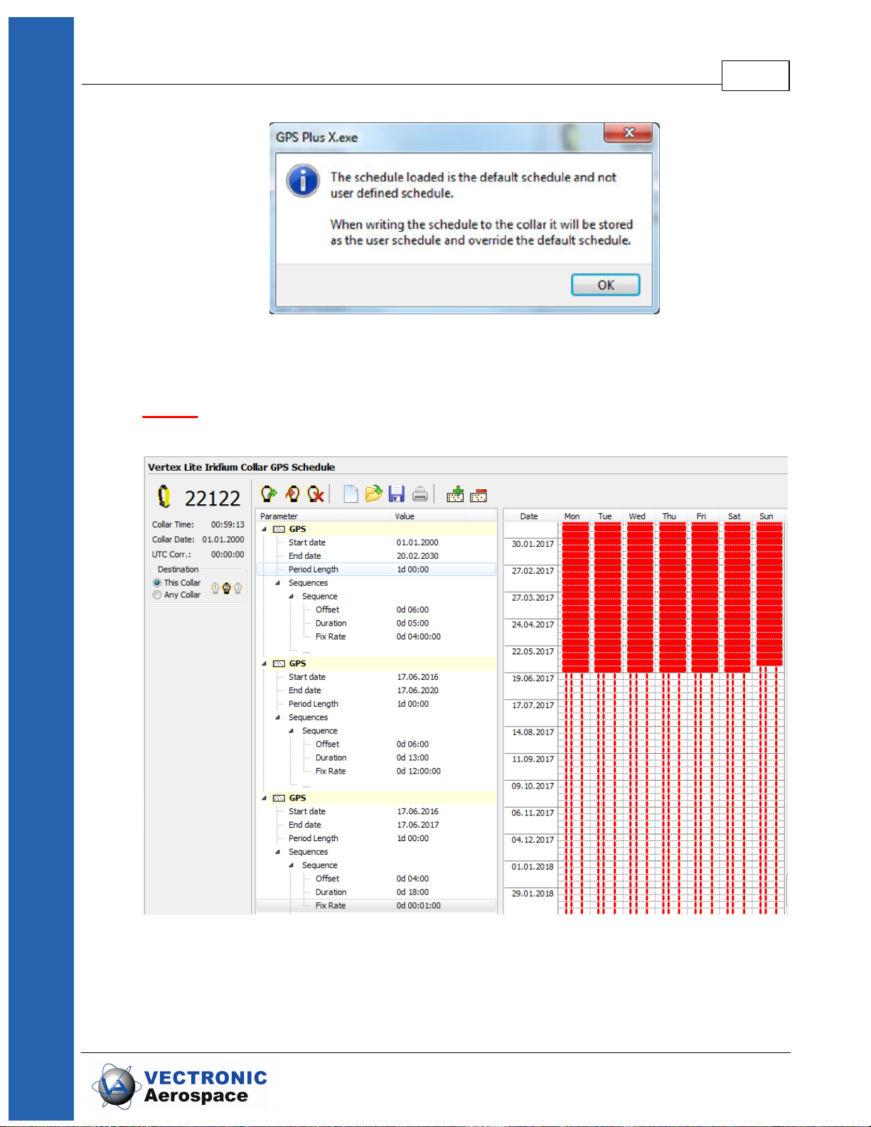
5.3.3.1 GPS schedule
Devices Remote Stick VERTEX Lite Schedules GPS
Devices USB Bluetooth Stick VERTEX Lite GPS
A GPS schedule consists of one or more rules specifying the date and time when the
collar will do GPS fixes. Each schedule consist of a varying set of rules each consisting
of:
Start Date: the date when the rule should start
End Date: the date when the rule should end
Period Length: the length of the period in which the Sequence for GPS
recording is repeated.
Sequence: The sequence is a time span within the period length between
© 2017 VECTRONIC Aerospace GmbH
Direct Collar Communication 46
you like to take GPS positions. Here you can define: Offset – it
defines the time span between the start of the period and the
recording of the first GPS position; Duration – period in which
the GPS positions will be recorded with the Fix Rate repetition;
Fix Rate – GPS position recording repetition rate.
NOTE: You can only take GPS fixes within the time span of the
period. This way, the sum of offset and duration must be
smaller than the value of the defined period length. If you like to
take only 1 GPS fix per sequence, the fix rate can equal the
duration value. If you have already two position recordings in
one sequence, you can delete the other sequence in the rule
editor.
You can use up to 292 rules within one schedule and get as complex as you want (rules
for all biological- and physical seasons, planned field operation, different study or
monitoring questions etc.).
NOTE: Iridium: Field studies have shown that the transmittal of 8 fixes per day in Mode4
– 4 fixes per message) has the best energy consumption / transmittal probability ratio.
Transmittal of more fixes per day will work as well but might result in a higher degree of
unsuccessful transmission attempts. Data will be reach you at some point but that might
take some time.
Recommendation: For safety reasons you should define at least one schedule starting
on 01.01.2000. If the collar's time is reset for any reason, the timer will start at this date
and will attempt to take one fix per week until another schedule starts or until the clock is
set to the correct UTC time by a successful GPS fix.
After changing the default rules to the user defined rules, you can choose if you like to
send the new schedule only to the selected collar or to all collars found in the Device
Search by setting up the Destination on the left side of the frame.
If you want to create a new schedule the first time (only the default schedule exists in the
collar), a notification window will appear when selecting the GPS schedule frame.
© 2017 VECTRONIC Aerospace GmbH
Direct Collar Communication 47
Figure 31: Notification window whenever a schedule node is activated for the first time
VERTEX Lite Iridium / GSM: You can send new schedules remotely.
NOTE: The collar will take one GPS fix per week when all schedule rules are in the
future. It will take a GPS fix every four hours when all schedules are outdated.
Figure 32: VERTEX Lite Iridium GPS schedule
© 2017 VECTRONIC Aerospace GmbH

5.3.3.2 VHF Beacon Schedule
Devices Remote Stick VERTEX Lite Schedules Beacon
Devices USB Bluetooth Stick VERTEX Lite Schedules
Beacon
The configuration of the VHF Beacon schedule is similar to the configuration of the GPS
schedule (see Schedules) but without setting the Fix Rate. You can only set the Start
Date and End Date, Period Length, Offset and Duration. The VHF beacon is active in
the time span between Offset and Duration.
For example: If you choose 6 hours for the Offset and a Duration of 4 hours with a Period
Length of 1 day, the VHF beacon will be active every day from 6.00 am to 10.00 am. In
difference to the GPS schedule, you can define max. 372 VHF beacon schedule rules.
Direct Collar Communication 48
Figure 33: VERTEX Lite Beacon Schedule
To save battery life, it might be useful to switch off the beacon during times when you will
not track your animal (e.g. during the night).
After setting up the VHF Beacon schedule, you can choose if you like to send the new
schedule only to the selected collar or to all collars found in the Device Search by setting
up the Destination on the left side of the frame. To send the VHF beacon schedule to the
collar / to the collars, press
© 2017 VECTRONIC Aerospace GmbH
Direct Collar Communication 49
NOTE: If all End Dates of the VHF schedule are outdated, the VHF beacon is switched
on 24 hours per day.
NOTE: With Globalstar communication you cannot change settings after deployment.
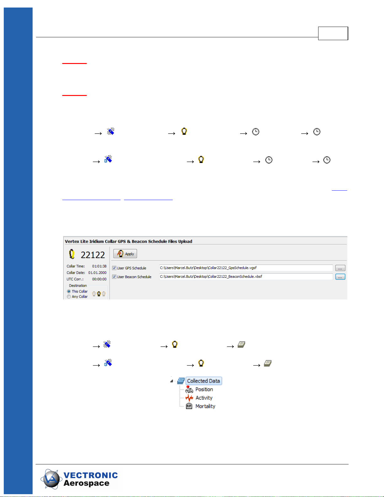
5.3.3.3 VHF Beacon & GPS Beacon Schedule Files Upload
Devices Remote Stick VERTEX Lite Schedules GPS &
Beacon Files Upload
Devices USB Bluetooth Stick VERTEX Lite Schedules GPS
& Beacon Files Upload
This setting is partly redundant to the separate VHF and GPS schedule creator (VHF
Beacon Schedule, GPS Schedule) enabling you to upload already prepared and stored
schedules to one or many collars simultaneously. You have no option to cross-check the
schedules again so you should be well experienced to use this feature instead of
the single schedule upload explained before.
5.3.4 Collected Data
Devices Remote Stick VERTEX Lite Collected Data
Devices USB Bluetooth Stick VERTEX Lite Collected Data
This frame shows the data retrieval options of the collars.
The main function of this node is to download the collar data. The output window and
Figure 34: GPS & Beacon files upload frame
Figure 35: Collected Data configuration node
© 2017 VECTRONIC Aerospace GmbH

Direct Collar Communication 50
functions differ but the main functions are identical for GPS, mortality, and activity data.
Reads data from the collar and displays it in the frame; this is not done
automatically as the download of data can take several seconds to minutes.
Saves data to the storage module; we advise to save all data from the collar,
even if you export them as data files.
This command erases the data stored on the collar. Please make sure that you
have stored the data before you use this command. Data cannot be restored
once deleted.
Recommendation: Please transfer the data to the GPS Plus X storage before you
export it or change any settings for the next collaring session.
© 2017 VECTRONIC Aerospace GmbH

Direct Collar Communication 51
Figure 36: Collected data output window (position)
All output windows include a filter rider to restrict the output file to a certain period and/or
also to certain data value attributes. You have to check each parameter to set in filter
parameters.
The output window for mortality data differs as it offers far less options (no quality
parameters, no KML-Export function and no chart option).
The content of the data will be explained in the specific sub-node.
NOTE: This is an output and export frame only. Changes (e.g date filter) effect the
exported files only, nothing is changed with the original data-set stored within GPS Plus
X.
© 2017 VECTRONIC Aerospace GmbH

5.3.4.1 Position
Start and End
Defines the period for which GPS fixes will be
shown. Other fixes are invisible. That way you
can exclude for example the testing phase.
Hide fixes less than
Defines a quality parameter for the GPS fixes
whereas 3D. Val. (Validated) refers to the best
possible GPS fix (number of satellites used,
satellite signal quality etc). Please refer to the
main GPS Plus X manual for details.
Hide invalid altitude fixes
Check if you want to exclude GPS fixes with
values below -1000 or above 10000meters
height as this positions are impossible. The
height is the least secure value as it strongly
depends on referent points (geoid maps) which
can vary in quality and accuracy.
Devices Remote Stick VERTEX Lite Collected Data
Position
Devices USB Bluetooth Stick VERTEX Lite Collected Data
Position
The position node shows collected GPS data and allows the visualization and the export
of the data or parts of it. It’s divided into Filter, Export and Data.
Filter: Enables you to set some filters to alter the data set.
Direct Collar Communication 52
Figure 37: (Position) Filter- Collected Data node
© 2017 VECTRONIC Aerospace GmbH

Direct Collar Communication 53
ASCII
has equal sized (number of characters) fields
for every row and thus can be easily read by
humans (as a table). File: *.txt
Spreadsheet
is machine readable, which means table
entries are separated by a freely definable
character (e.g. comma) that can be defined in
the options form. File: *.csv
KML-Google Earth
is a XML format used in Google Earth and
some other mapping software to display
tracks, points of interest, etc.
Clamp to ground
if checked, the path displayed in Google Earth
is always shown as anchored to the ground,
regardless of its altitude or if terrain is enabled
or not
Extrude Pat
if checked, the path displayed in Google Earth
is always shown as anchored to the ground,
regardless of its altitude or if terrain is enabled
or not
Track visible
if checked, the track will be visible in Google
Earth as coloured line
Fixes visible
if checked, all fixes will be visible in Google
Earth as coloured icons
LMT in record info
if checked, the local mean time according to
Export: This section defines the export formats. You can check several options and GPS
Plus X will create a file for each format.
Figure 38: Export window- Collected Data node
© 2017 VECTRONIC Aerospace GmbH
Direct Collar Communication 54
the UTC correction of GPS Plus X will be
shown in Google Earth
Cam Heading
viewing direction of 0 – North, 90 – West, 180
– South, 270 - East
Cam Tilt
inclination of the camera, 0 – straight
downwards, 90 – horizontal into viewing,
direction, 180 – straight upwards, 270 horizontal into opposite viewing direction
No.
line index, dependent on time stamp; this index
number is created when data are read out of the
collar and will not be changed when data are
filtered (this way, “data gaps” caused by filtering
are easily detectable)
Collar ID
ID of the collar from which the positions have
been downloaded
UTC date and time
time in Universal Time Coordinated (UTC,
equivalent to GMT, without daylight saving time/
summer time)
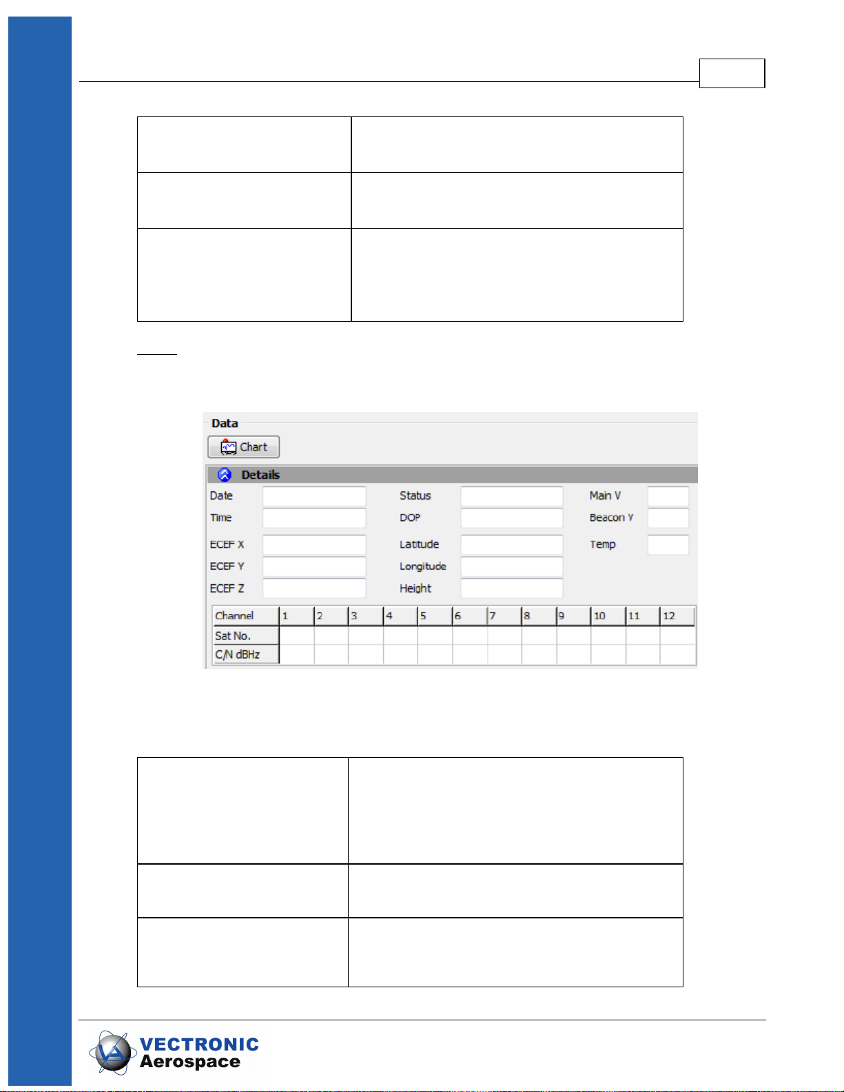
Data: This window shows all GPS positions with their unique values (DOP, Satellites
used etc – see below). A click on a single fix (line) will show its values in the upper part
for better visualization.
Figure 39: Data window- Collected Data node
© 2017 VECTRONIC Aerospace GmbH

Direct Collar Communication 55
LMT date and time
local mean time, depending on the value set in
UTC Correction (see System UTC Correction)
Origin
shows where the the message originates from
SCTS Date/Time
the date/time when the message receives the
provider
ECEF X, Y, and Z
coordinates in the Earth Centred Earth Fixed
coordinate system
Latitude, Longitude, Height
geographical position based on WGS84
No.
line index, dependent on time stamp; this index
number is created when data
are read out of the collar and will not be
changed when data are filtered (this
way, “data gaps” caused by filtering are easily
detectable)
Collar ID
ID of the collar from which the positions have
been downloaded
Chart: The Chart function plots the GPS data in a basic graph. A nice feature to get a
first overview about distribution and migration pattern. You can zoom in by drawing a
square with your mouse or use the option riders within (File, View) which includes a
save option as well.
Figure 40: Basic graphic plotting of GPS data- Collected Data node
© 2017 VECTRONIC Aerospace GmbH

Direct Collar Communication 56
UTC data and time
time in Universal Time Coordinated (UTC,
equivalent to GMT, without daylight
saving time/summer time)
LMT date and time
local mean time, depending on the value set in
UTC Correction
Origin
shows where the message originates from
SCTS Date/Time
the date/time when the collar has been read out
ECEF X, Y and Z
coordinates in the Earth Centred Earth Fixed
coordinate system
Latitude, Longitude and
Height
geographical position based on WGS84
DOP
(Dilution of Precision) value for the geometric
constellation of the received GPS satellites
Fix Type
quality of fix obtained
3D Error
shows the difference [m] between the real
position and the transmitted
position
Sats used
number of satellites used for the fix.
Sat No/ C/NO [dBHz]
channels of the GPS receiver with two columns
each containing the received
satellite number and the carrier to noise ratio in
dBHz
Main [V]
voltage of the main battery in Volts
Mortality Status
shows if the animal was deemed alive or dead
Beacon [V]
voltage of the beacon battery in Volts
Temp [°C]
Ambient temperature
5.3.4.2 Activity
Devices Remote Stick VERTEX Lite Collected Data Activity
Devices USB Bluetooth Stick VERTEX Lite Collected Data
Activity
Filter: Enables you to set some filters to alter the dataset.
© 2017 VECTRONIC Aerospace GmbH

Direct Collar Communication 57
ASCII
has equal sized (number of characters) fields for
every row and thus can be easily read by humans
(as a table). File: *.txt
Spreadsheet
is machine readable, which means table entries
are separated by a freely definable character (e.g.
comma) that can be defined in the options form.
File: *.csv
Figure 41: Activity Data Filter
Export: This section defines the export formats. There are only two formats available for
the activity data export.
Figure 42: Activity data export
Data: This window shows all activity data stored in the collar.
© 2017 VECTRONIC Aerospace GmbH

Direct Collar Communication 58
Figure 43: Activity Data Frame
Press to see a visualization of the data.
5.3.4.3 Mortality
Devices Remote Stick VERTEX Lite Collected Data
Mortality
Devices USB Bluetooth Stick VERTEX Lite Collected Data
Mortality
Filter: Enables you to set some filters to alter the dataset.
Figure 44: Mortality Data Filter
Export: This section defines the export formats. There are only two formats available for
the mortality data export.
© 2017 VECTRONIC Aerospace GmbH

Direct Collar Communication 59
ASCII
has equal sized (number of characters) fields for
every row and thus can be easily read by humans
(as a table). File: *.txt
Spreadsheet
is machine readable, which means table entries
are separated by a freely definable character (e.g.
comma) that can be defined in the options form.
File: *.csv
Figure 45: Mortality Data Export
Data: This window shows all mortality Events stored in the collar. positions with their
unique values (DOP, Satellites used etc – see below). A click on a single fix (line) will
show its values in the upper part for better visualization.
Figure 46: Mortality Data Overview
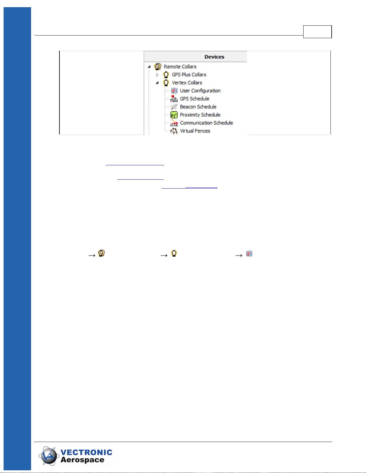
6 Remote Collar (Communication)
Devices Remote Collars VERTEX Collars
This chapter deals with the remote communication to the collar using Iridium satellite
communication or GSM communication.
© 2017 VECTRONIC Aerospace GmbH
Remote Collar (Communication) 60
Figure 47: Remote Collars tree shows the option list of this node. It shows GPS Plus Collars as
well as VERTEX collars.
The first node (User Configuration) contains the configuration you can change.
The second node (GPS Schedule) is used to define and send GPS schedules to one or
more collars and the third node (Beacon Schedule) includes the same options for VHF
Beacon schedules.
The last 3 nodes (Proximity Schedule, Communication Schedule, Virtual Fences) are for
VERTEX Plus collars only and are not applicable for VERTEX Lite Collars.
6.1 Remote User Configuration
Devices Remote Collars VERTEX Collars User Configuration
© 2017 VECTRONIC Aerospace GmbH
Remote Collar (Communication) 61
Figure 48: Remote User Configuration
© 2017 VECTRONIC Aerospace GmbH

Remote Collar (Communication) 62
All options are explained in Chapter User Configuration and Schedules.
NOTE: Please keep in mind that some changes will affect not only the collar but also
your ability to reset them. All changes should be well planned and documented.
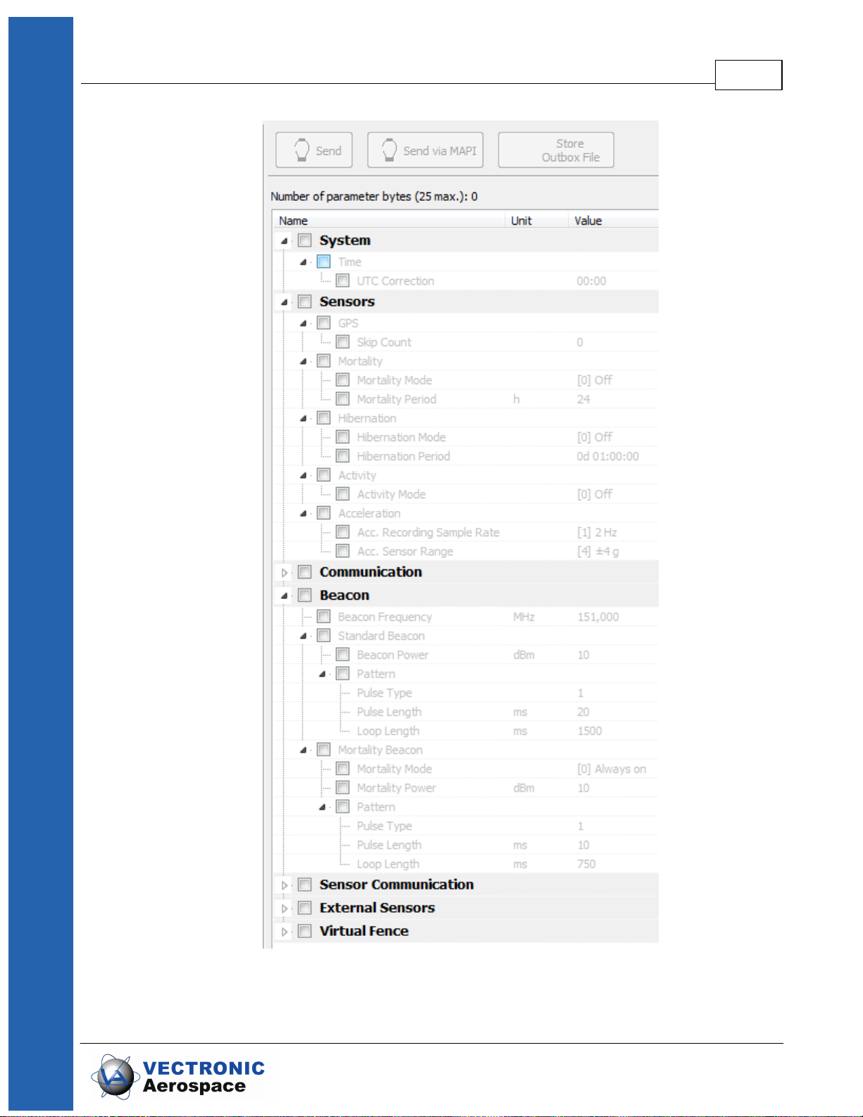
Figure 49: Remote VERTEX Collar Configuration
You can check the parameters you want to change and alter the values. The message
can contain a maximum of 25 bytes only. The program indicates when your changes
exceed that threshold. Please send two
messages instead including a part of the changes only. The collar will receive both and
store all changes.
To send out commands you have to do the following steps:
1. Check the Parameters you want to change
2. Change the parameter to new values
3. Check the collar(s), one or more according to left sided list you want to send the
new configuration to
4. Press the send Button
5. Optionally: click on “Store Outbox File” for third party applications.
6. Follow up on collar command reception (in Data Collar Reception
Status)
© 2017 VECTRONIC Aerospace GmbH

NOTE: check the changes before sending them as you might have problems to change
them again (e.g. adding skip count, raising positions / messages fewer messages
from the collar, fewer communication windows for you).
NOTE: make sure you have chosen the correct collars only.
NOTE: Status and further information about Remote Commands can be seen in Data
Remote Command Status. Please keep track on your changes for you and your
planning but also for us if you need support at some point.
6.2 Remote GPS Schedule
Devices Remote Collars VERTEX Collars GPS Schedule
The GPS schedule editor is identical to the one described in GPS schedule. Any
schedule send to the collar will erase the existing one on the collar, meaning you will
have to include all rules of the first one. There is a size limitation for an Iridium / GSM
Message, one message to the collar can contain 108 bytes only, respectively 4-7 rules.
You might have to stick to some more basic rules, respectively plan for a certain period
and resend updates from time to time.
Remote Collar (Communication) 63
The software GPS Plus X will warn you whenever your schedule is invalid in rule usage
or size and abort the upload.
For remote communication with a GSM collar with customer SIM card, a Ground Station
is necessary. If you do not own one, please contact our customer service.
For remote communication with an Iridium collar you need to set further configurations
(email address,...) to communicate with your collar. Therefore refer to the GPS Plus X
software manual and search for 'Collar Command Destinations'.
The steps how you send out commands to your collar are explained in the GPS Plus X
software manual, please search for 'Remote communication via GSM and IRIDIUM'.
6.3 Remote Beacon Schedule
Devices Remote Collars VERTEX Collars Beacon Schedule
The VHF Beacon schedule editor is identical to the one described in VHF Beacon
schedule. Any schedule send to the collar will erase the existing one on the collar,
meaning you will have to include all rules of the first one.
There is a size limitation for Iridium / GSM Messages which means you won’t be able to
make new ones as complex as the first one. An Iridium / GSM message to the collar
© 2017 VECTRONIC Aerospace GmbH

can contain 108 bytes only, respectively 5-9 VHF Beacon rules. You might have to stick
to some more basic rules, respectively plan for a certain period and resend updates
from time to time.
The software GPS Plus X will warn you whenever your schedule is invalid in rule usage
or size and abort the upload.
7 Calculate Collar Lifetime
This command estimates the lifetime of your VERTEX Lite Collar and can be found in
the Tools menu of GPS Plus X. (Tools Calculate VERTEX Collar Lifetime)
Remote Collar (Communication) 64
Figure 50: Tools Menu
Select your collar (e.g. VERTEX Lite Iridium and battery size) and check the settings
(Position Transmission & Beacon).
NOTE: You will find recommendations to the “Position Transmission” in the specific
chapter (Iridium Communication) and we recommend to stick to the default values for
the Beacon settings (VHF Beacon).
Now you can enter a GPS and VHF Beacon schedule which are described in chapter
GPS schedule and VHF Beacon schedule. After you have selected all the options for the
collar, press or to start the calculation. When pressing
or while the calculation process is running, you will cancel the
calculation. It might be useful to save the settings using the icon as this schedule
could later be used for collar configuration. The icon enables you to load schedules
into the calculation tool, potentially retrieved from the collar as described in chapter
Schedules.
© 2017 VECTRONIC Aerospace GmbH

Calculate Collar Lifetime 65
Figure 51: VERTEX Lite Collar Calculate Lifetime
The output contains the collar lifetime for the main battery whereby all functions
(GPS,VHF and satellite communication) are working and the VHF Beacon battery
lifetime whereby only the VHF Beacon will be powered for collar retrieval. It will outlive
the main battery to a degree as the back up battery size which differs for the models (1C
to 13D collar).
The window shows 3 values (Best case, Average and Worst case). In a best case
scenario, the collar is assumed to receive the ephemerides very fast and is able to
calculate its position within 45 s in Average. The Average scenario assumes an
average GPS fix calculation time of 90 seconds which should be the case for most
collars. A worst case scenario calculates with an average fix time of 180s. That might
apply in a heavily forested or relieved area where the collar has difficulties to get contact
to satellites.
© 2017 VECTRONIC Aerospace GmbH

The Start and End Date depend on your starting point (main option frame).
NOTE: Several factors effect the calculation time such as satellites in range again
affected by the habitat and potential obstacles (e.g. thick canopy) and time between two
fixes and potential benefit of using existing ephemerides data (fixes within an hour).
Recommendation: please calculate with the average scenario to start with especially
when you use a Globalstar collar or work in forested habitats.
8 Test the collar
It is recommended to test the collar in advance if GPS positions are received and
transmitted as programmed before you deploy it on the animal.
1. Remove the magnet from the electronic housing (not the Drop Off magnet!)
2. Place them outdoors with clear view to the sky (NOTE: Place the collars about 1m
apart otherwise their signals might interfere and effect the testing)
Calculate Collar Lifetime 66
3. Listen for the VHF beacon signal with your tracking receiver (NOTE: check settings
for frequency and communication windows for beacon before)
4. Wait for incoming messages (NOTE: check for expected time frames first)
5. Process incoming data and check signal quality etc.
6. Send reconfiguration commands remotely
7. Deactivate the collar by reattaching the magnet to the electronic housing
NOTE: To save battery life, leave the magnet on the collar during storage and do not
leave the collar connected to your computer if you do not use it. Disconnect the battery
pack if you store the collar for months.
9 Attach the collar to the animal
The collar has no forward or backward side so you can deploy it to your liking.
Make sure the belt fits perfectly to the animal's neck. If it is too loose, the animal may
get it off. In worst case the animal might get injured by a collar too loose or tight.
Cut the overhanging belt part and smooth the cutted edge.
To achieve the best possible GPS signal, the GPS antenna should be on top of the
animal’s neck. The GPS antenna is inside the electronic case facing upwards. If the
© 2017 VECTRONIC Aerospace GmbH

Attach the collar to the animal 67
collar is adjusted to the circumference given on the order information sheet, the
electronic case is located exactly on top of the animal's neck.
Figure 52: Collar circumferences (a) Predefined circumference: Electronic case is exactly on
top of animal’s neck, best possible GPS reception. (b) Up to ±10% variation from predefined
circumference: Electronic case is slightly on side of animal’s neck (c) bad or no GPS reception
Make sure the magnet is removed from the electronic housing and from the Drop Off,
otherwise it stays deactivated and will not perform any GPS fixes or transfer data, and
the Drop Off will not release the collar.
If you need help or advice please contact our customer service. We will gladly bring you
in touch with other scientist working on similar species.
NOTE: Please do not shorten the belt beyond the perforated beltpart as you would
possibly cut and thereby damage the VHF antenna. If you need further shortening,
please get in touch with our customer service.
NOTE: Make sure the magnets are removed from the housing, otherwise the collar
stays deactivated and the Drop Off will not release the collar.
10 Battery options
The VERTEX Lite Collar enables the usage of different battery sizes. All batteries can
be coupled with a Drop Off system.
The battery design itself depends on the belt shape (oval, round and oval/round) and the
usage of a Drop Off system. The following table gives an overview about battery types
and weights with or without Drop Off.
© 2017 VECTRONIC Aerospace GmbH

Battery for round collar:
without Drop Off
with Drop Off
1C IG
128 g
186 g
1D IG
205 g
300 g
2D IG
329 g
430 g
3D IG
492 g
580 g
4D IG
616 g
708 g
5D IG
800 g
855 g
7D IG
Ca. 1050 g
without Drop Off
with Drop Off
1C AG
128 g
186 g
1D AG
234 g
309 g
2D AG
348 g
456 g
3D AG
512 g
603 g
4D AG
634 g
716 g
5D AG
800 g
855 g
7D AG
Ca. 1050 g
without Drop Off
with Drop Off
3D_R
635 g
807 g
4D_R
792 g
984 g
5D_R
951 g
Not available
Battery for oval collar:
Battery options 68
curved batteries:
© 2017 VECTRONIC Aerospace GmbH

11 Changing of battery pack
All VERTEX Lite Collars have user changeable battery packs (exception: 1c- fix
battery). Make sure to follow the instructions to prevent any damage to the collar and its
parts when changing the battery pack.
NOTE: If you change the battery of a collar with Drop Off, please note the Drop Off
number on the battery housing. This ensures that you can reach the Drop Off that you
actually want to reach when retrieving the collar, especially for remote Drop Offs!
NOTE: Be careful when un- or replugging the battery connector pins since they can
break if bended.
NOTE: Store the battery package at room temperature.
There are 3 different belt shapes. For each shape the battery changing procedure
differs a little. Please follow the links for the respective instructions.
Changing of battery pack 69
Oval collar
Round Collar, standard battery pack
Round collar, curved battery pack
11.1 Oval Collar
Unscrew the two nuts attaching the battery pack to the adjustable side of the collar with
an 8 or 7 mm (depending on collar size) hexagon socket wrench (delivered with the
collar). Remove the black base plate. The screws are integrated into the battery pack
and cannot be removed.
Figure 53: Battery Connector on oval collar
© 2017 VECTRONIC Aerospace GmbH

Changing of battery pack 70
Figure 54: Removing the battery connector from oval collar
Unscrew the two nuts and remove the washer on the non-adjustable side of the collar
with the battery connector. Carefully pull the battery connector from the battery pack
(Figure above, left). The battery pin socket is located between the two screws (Figure
above, centre).
To attach a new battery pack, replace the O-ring on the battery plug and carefully push
the three threaded pins of the connector plug into the connector socket (Figure above,
right). Be careful to avoid any damage to the connector! Place the washer on the
threaded pins and reattach the collar with new self-locking nuts to ensure that the O-ring
of the nuts is not damaged.
NOTE: After you changed the battery pack of your collar, a GPS coldstart is necessary.
For this please refer to GPS Monitor.
11.2 Round Collar, standard battery pack
Figure 55: Battery connector on round collar, standard battery pack
Remove the screws attaching the bracket to the battery pack with an 8 or 7 mm
(depending on collar size) hexagon socket wrench (delivered with the collar). Start with
the screws on the adjustable side and then remove the screws attaching the battery
connector.
© 2017 VECTRONIC Aerospace GmbH

Changing of battery pack 71
Figure 56: Removing the battery connector from round collar, standard battery pack
Unscrew the nuts attaching the bracket to the collar to gain more flexibility around the
battery pack (Figure above, left). Be careful when moving the battery pack. Unplug
the battery connector by carefully pulling the bracket away from the battery pack (Figure
above, centre). Be careful to avoid any damage to the connector!
To attach a new battery pack remove the O-ring around the battery connector (be careful
not to damage the cables). Replace the O- ring on the battery plug. Carefully push the
three threaded pins of the connector plug into the connector socket. Tighten the bracket
to the collar with new self-locking nuts and screw the battery pack to the bracket with
unused screws to ensure that the self-locking coating on the screws is not damaged.
Apply fresh O-ring around the battery connector to protect the contacts from humidity
and to prevent sticks and debris from being caught between collar and battery pack.
NOTE: After you changed the battery pack of your collar, a GPS coldstart is necessary.
For this please refer to GPS Monitor.
11.3 Round Collar, curved battery pack
Figure 57: Battery connector on round collar, curved battery pack
First remove the nuts for closing the collar with an 8 or 7 mm (depending on collar size)
hexagon socket wrench (Figure above, centre), then open the screws attaching the
battery pack to the collar with a 3 mm hexagon socket key (“Inbus” or “Allen key”,
delivered with the new battery pack) starting with the exterior screws (Figure above,
right).
© 2017 VECTRONIC Aerospace GmbH

Changing of battery pack 72
Figure 58: Removing the battery connector from round collar, curved battery pack
Unplug the battery connector by pulling the collar away from the battery pack (Figure
above, left). You can support this by very carefully wedging a flat screwdriver between
the battery connector and the battery pack (Figure above, right). Be careful to avoid any
damage to the connector!
Figure 59: Battery connector and plugs on round collar, curved battery pack
Above you can see the battery socket (left) and pins (right). To attach a new battery
pack, exchange the O-ring on the battery plug and carefully plug the three threaded
battery pins into the socket.
Figure 60: Attachment of curved battery pack to round collar with two metal base plates (left)
and two Fastlock washers (right)
In older collars, the battery packs are fixed to the belt with six screws and three metal
© 2017 VECTRONIC Aerospace GmbH

Changing of battery pack 73
base plates. To avoid the base plates pressing onto the battery cable, new batteries are
fixed with only two metal base plates and two Fastlock washers (Figure above).
Figure 61: Attachment for curved battery pack on round collar. Left: metal base plate; centre:
screw and Fastlock washer; right: angle to attach screws
Put the black washer (Figure above) with the convex side onto the collar (otherwise you
will not be able to countersink the screw head) and carefully attach the collar with unused
screws beginning with the central pair and then the pair at the side next which you will
open to deploy the collar. Note that the exterior threads run radially to the curved surface
of the battery pack. Take care to arrange the screw correctly to avoid damaging the
thread. Countersink the screws into the battery pack.
NOTE: After you changed the battery pack of your collar, a GPS coldstart is necessary.
For this please refer to GPS Monitor.
12 The Vertex Lite collar with integrated UHF ID-Tag
Devices Remote Stick Radio Monitor
The VERTEX Lite Collar can be equipped with an internal UHF ID Tag to be used in
interaction studies. They send out an unique signal which can be observed by VERTEX
Plus collars (with UHF communication) recording all encounters and separation events.
The node Radio Monitor in the Devices tree allows you to check if your devices work.
You can check ID / Separation Tag, Mortality Implant and Vaginal Implant by enabling
one of these devices. For testing the device select ID / Separation Tag and take the
magnet off the device and click on . The Listening Frequency [MHz] of the USB
Remote Stick is preset but can be changed if necessary to the transmit frequency of the
UHF ID-Tag. If messages from this device are received, you will get a list with status
messages of the corresponding device. With you can delete the received
entries. It will be shown with the same ID number as the collar.
© 2017 VECTRONIC Aerospace GmbH

The Vertex Lite collar with integrated UHF ID-Tag 74
Figure 62: USB Remote Stick Radio Monitor frame
13 Specification
13.1 Environmental specification for the collar
Operational temperature range: -40°C to +70°C
Operating humidity range: <= 100% RH (relative humidity)
Storage temperature range: -45°C to +80°C
Storage humidity range: <= 100% RH (relative humidity)
Battery:
Do not short-circuit, recharge, puncture, incinerate, crush, immerse or expose battery to
temperatures above the declared operating temperature range of the product. Risk of
fire or explosion!
Storage:
Store in a cool (preferably below 30°C) and ventilated area, away from moisture,
sources of heat, open flames, food and drink. Keep adequate clearance between walls
and batteries. Temperature above 100°C may result in battery leakage and rupture.
Other:
Lithium batteries are not rechargeable and should not be tentatively charged.
© 2017 VECTRONIC Aerospace GmbH

Specification 75
Disposal Considerations:
Do not incinerate, or subject cells to temperatures in excess of 100°C. Such abuse
can result in loss of seal, leakage, and/or cell explosion.
Do not dispose of the battery with the regular garbage, but in accordance with
appropriate local regulations.
13.2 Declarations of Conformity
Declaration of Conformity for USA
This device complies with Part 15 of the FCC Rules. Operation is subject to the
following two conditions:
(1)this device may not cause harmful interference, and
(2)this device must accept any interference received, including interference that may
cause undesired operation.
Usually this is followed by the following FCC caution:
Any changes or modifications not expressly approved by the party responsible for
compliance could void the user's authority to operate this equipment.
© 2017 VECTRONIC Aerospace GmbH

Specification 76
Type designation:
GPS Plus Globalstar Collar
Type or model:
---
Serial no.:
---
Applied standards/ directives were:
Title or description of the standard:
EN 300 440-1,-2 V1.5.1/ V1.3.1
Short Range Devices 1- 40 GHz
EN 301 441 V1.1.1
Satellite Earth Stations and Systems (SES)
EN 301 489-1,-3 V1.8.1 / V 1.4.1
EMC for SRD 9 kHz – 40 GHz
EN 301 489-20 V1.2.1
EMC for Mobile Earth Stations (MES) used in the
Mobile Satellite Services (MES)
EN 60950-1:2006
Safety of information technology equipment
Company:
VECTRONIC Aerospace GmbH
Name:
Mr. Robert Schulte
Street:
Carl-Scheele-Str. 12
Location:
12489 Berlin
Country
Germany
Telephone:
+49 (0) 30 6789 4990
Declaration of Conformity for CANADA
Operation is subject to the following two conditions:
(1)this device may not cause interference, and
(2)this device must accept any interference, including interference that may cause
undesired operation of the device.
Usually this is followed by the following RSS caution:
Any changes or modifications not expressly approved by the party responsible for
compliance could void the user's authority to operate this equipment.
Declaration of Conformity
acc. to 1999/5/EC (R&TTE), 2004/108/EC (EMC directive), 2006/95/EC (Low voltage
directive)
We declare that the following product,
complies with the technical regulations and their valid changes at the time of issuing this
declaration.
Address of the manufacturer or his authorized representative:
© 2017 VECTRONIC Aerospace GmbH

Specification 77
Fax:
+49 (0) 030 6789 5230
Email:
mail@vectronic-aerospace.com
Name:
Mr. Robert Schulte
Telephone:
+49 (0) 30 6789 4990
Fax:
+49 (0) 30 6789 5230
This declaration was issued under the sole responsibility of the manufacturer and if required
of his authorized representative:
Contact person:
The product carries the CE mark “ ”
Berlin, 2010-08-23
. . . . . . . . . . . . . . . . . . . . . .
Robert Schulte
13.3 Certificates
© 2017 VECTRONIC Aerospace GmbH

Specification 78
© 2017 VECTRONIC Aerospace GmbH

Specification 79
© 2017 VECTRONIC Aerospace GmbH
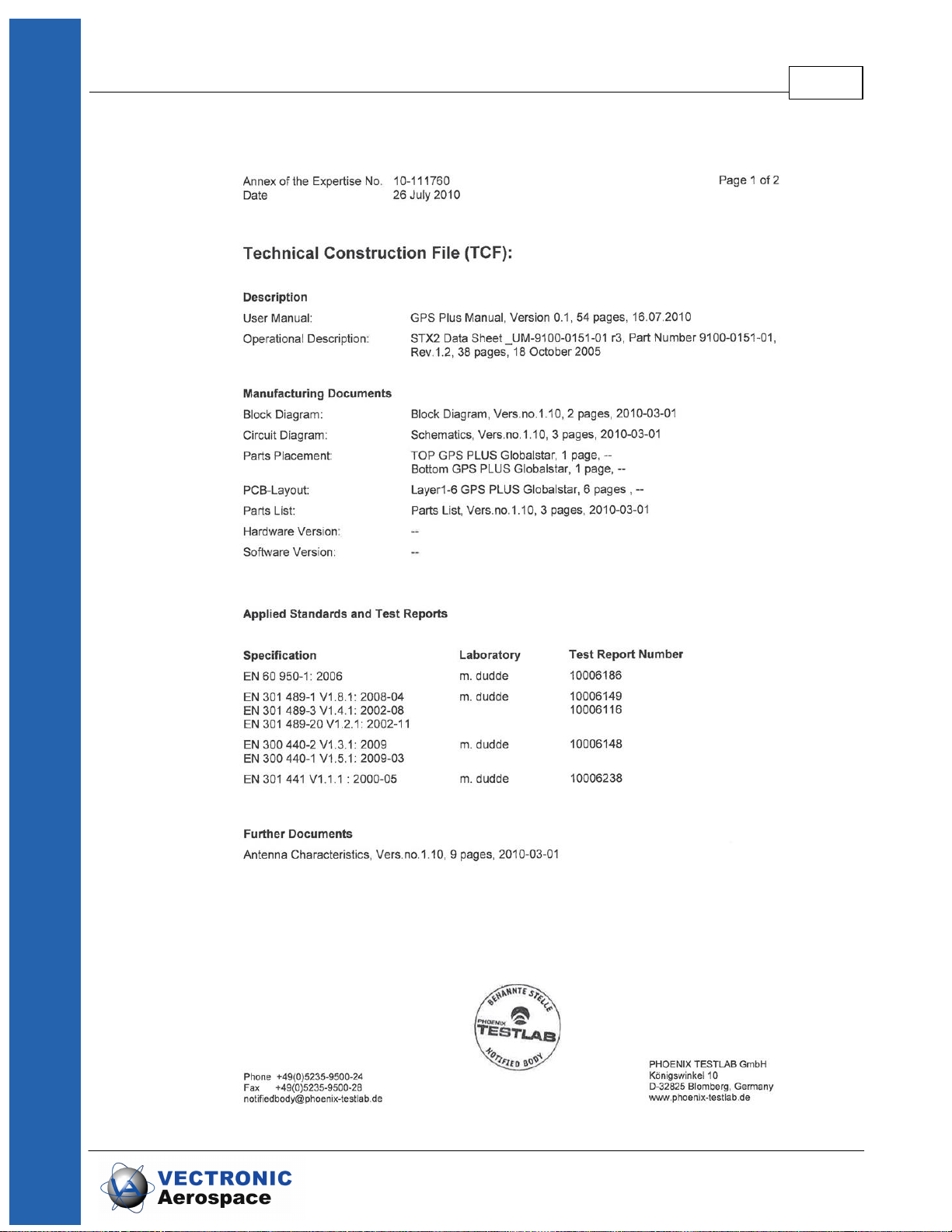
Specification 80
© 2017 VECTRONIC Aerospace GmbH

Specification 81
© 2017 VECTRONIC Aerospace GmbH

Specification 82
© 2017 VECTRONIC Aerospace GmbH

Specification 83
© 2017 VECTRONIC Aerospace GmbH

Specification 84
© 2017 VECTRONIC Aerospace GmbH

Specification 85
© 2017 VECTRONIC Aerospace GmbH

Specification 86
© 2017 VECTRONIC Aerospace GmbH

Specification 87
© 2017 VECTRONIC Aerospace GmbH
 Loading...