

Page 1
TempTrackr™ Wireless
267 Lowell Rd, Hudson NH 03051, USA | Phone: 1.888.328.7661 | Fax: 1.888.329.8328 | www.sengenuity.com
System Kit
Quick Setup Guide and
Operation Manual
Helping Customers Innovate, Improve & Grow
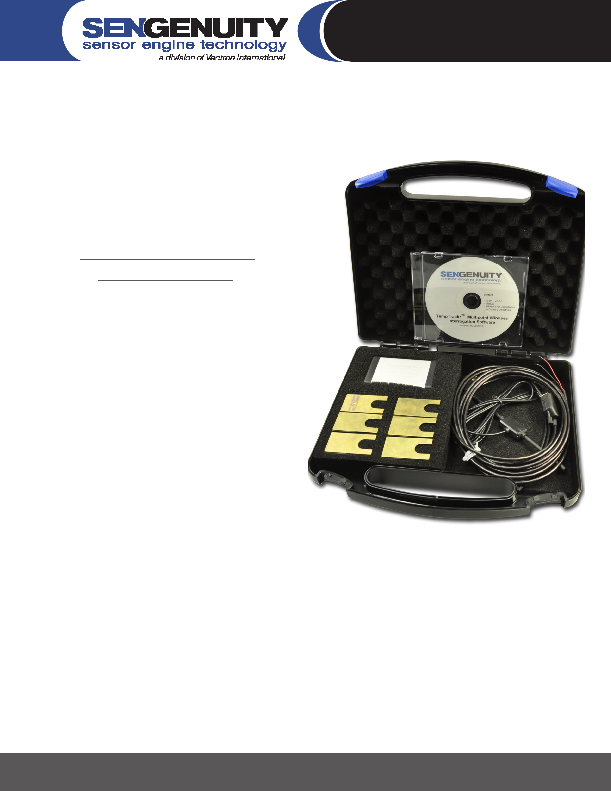
The TempTrackr™ Multipoint Starter kit includes:
Three or Six wireless temperature sensors•
One wireless interrogation unit•
One dipole interrogation antenna•
One RS232/RS485 cable•
One software CD with the TempTrackr™ Wireless•
Interrogation Software
Please contact SenGenuity if any item is either missing
or damaged. The wireless interrogation unit needs to be
powered by a 5V±5% DC power-supply. All temperature
sensors are interrogated by one interrogation antenna.
The TempTrackr™ Starter Kit can be setup in three simple
steps:
Install and Congure TempTrackr™ Wireless Interrogation Software1.
Setup and connect wireless interrogation unit2.
Setup, locate and calibrate wireless sensors3.
Page 2
267 Lowell Rd, Hudson NH 03051, USA | Phone: 1.888.328.7661 | Fax: 1.888.329.8328 | www.sengenuity.com
Helping Customers Innovate, Improve & Grow
Step 1
Step 1: Install and congure TempTrackr™ Wireless
Interrogation Software
Insert Interrogation Software CD into PC/Laptop drive. The
installation process should begin automatically. If this does not
happen, please access the CD drive using Windows Explorer and
double-click the “setup.exe” icon as shown in Figure 1.
Figure 2: Accessing the setup.exe icon via Windows Explorer
Step 1: continued...
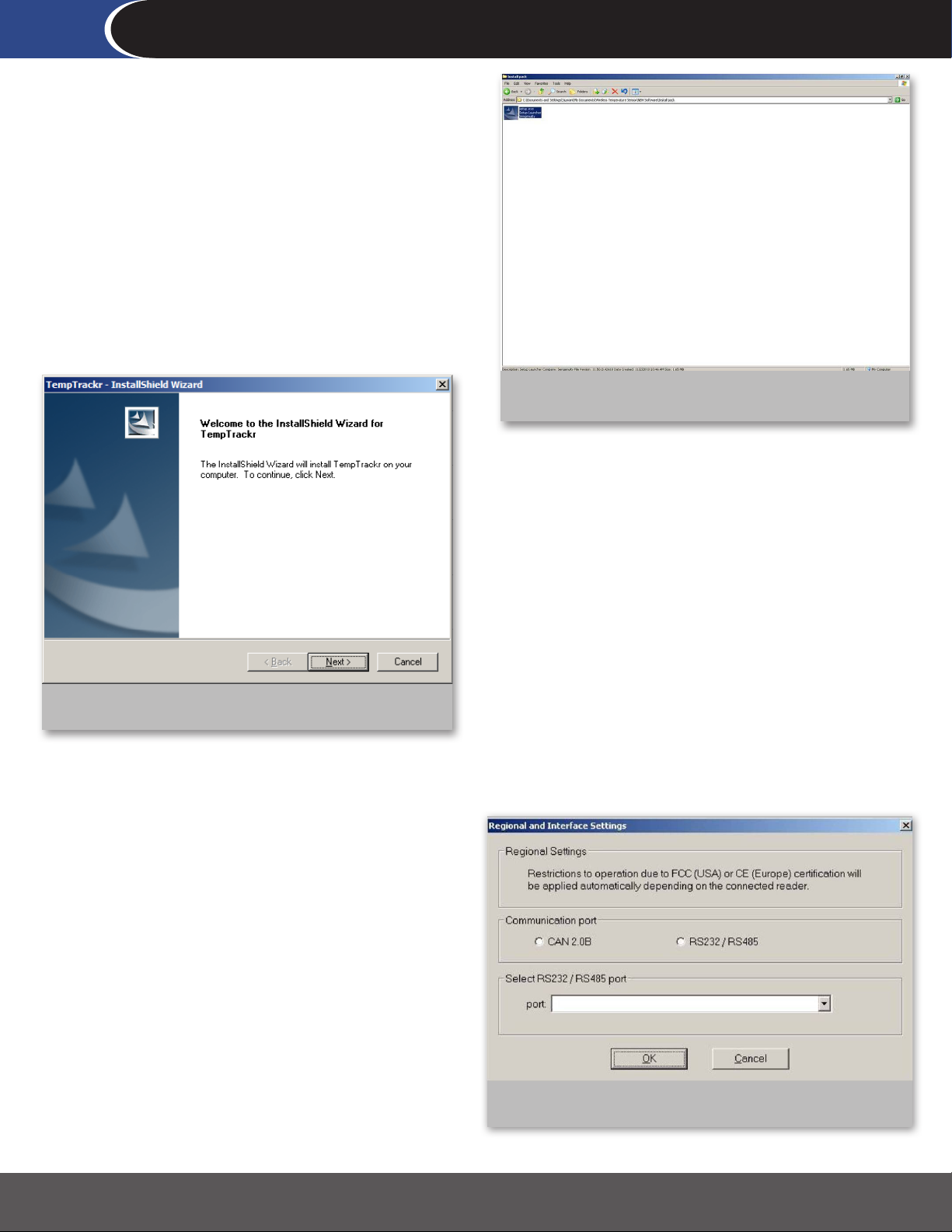
Figure 1: InstallShield Window for TempTrackr™
Step 1: continued...
The software will apply regulatory restrictions based on your
geographic region. The FCC complaint version of the kit will
include software that conforms to FCC requirements. The CE
compliant version of the kit will include software that conforms to
CE requirements:
FCC requirements impose the following restrictions on the •
reader:
The reader will read sensors only once every 30s.•
The reader will only make use of one antenna. The other •
two antenna ports are deactivated on FCC compliant
readers.
CE requirements restrict the reader to only operate in the 433 •
MHz ISM-Band. This means that you will only be able to read
one sensor with a CE compliant reader.
Please use the InstallShield Wizard, shown in Figure 2, to complete
the installation process. Successful installation will result in the
creation of a directory called TempTrackr in the path C:\Program
Files\Sengenuity\TempTrackr.
Start the Software from the Windows Start Menu or by doubleclicking the WSR-T2 icon from the directory in which the software
has been installed.
Figure 3: Regional setting for regulatory compliance
Page 3
267 Lowell Rd, Hudson NH 03051, USA | Phone: 1.888.328.7661 | Fax: 1.888.329.8328 | www.sengenuity.com
Helping Customers Innovate, Improve & Grow
Step 2
Step 2: Setup and connect wireless interrogation
unit
Please select the communication interface (CAN or RS232/RS485)
to communicate with the wireless interrogation unit. If you
select the RS232/RS485 option, please select the appropriate
communication port on your PC/Laptop. Most kits will include an
RS232/RS485 cable and will not include a CAN adapter and cable.
Therefore please select the RS232/RS485 option when setting up
the kit.
Figure 4: Communication Interface
Figure 5: Wireless Interrogation unit connected to Antenna
and RS232/RS485 cable
Step 2: continued...
Step 2: continued...
As shown in Figure 5, connect the wireless interrogation unit to
RS232/RS485 cable. The Dipole Antenna should have already
be connected to the reader when it was delivered to you. If you
receive a reader with the antenna NOT connected please do not
use it if you are in the United States. You WILL be in violation
of FCC regulations. Please contact SenGenuity to arrange for a
replacement kit to be sent to you.
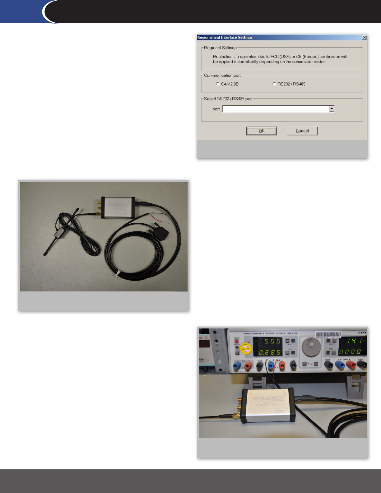
Connect the Wireless Interrogation Unit to a power supply
(5V±5% DC; 350mA) as shown in Figure 6. You can now connect
the RS232/ RS485 cable to your PC/laptop.
Figure 6: Wireless Interrogation unit connected to Power
Supply
Page 4

267 Lowell Rd, Hudson NH 03051, USA | Phone: 1.888.328.7661 | Fax: 1.888.329.8328 | www.sengenuity.com
Helping Customers Innovate, Improve & Grow
Step 3
Step 3: Setup, Locate and Calibrate Wireless Sensors
Place the sensors at designated target locations. Figure 7 shows
a wireless temperature sensor. Please note the orientation of the
antenna in the inset (picture of sensor without the cap) to correctly
interpret Figure 8.
Figure 7: Wireless Temperature Sensor
Figure 8: Incorrect and Correct Setup
Step 3: continued...
There are some important guidelines that should be followed
when locating the sensors:
The ● minimum distance between two sensors must be 4
inches (~10 cm).
The ● minimum distance between any given sensor and
the interrogation antenna must be 12 inches (~31 cm).
The ● maximum interrogation distance between the
interrogation antenna and the sensor is heavily inuenced
by the local RF environment. In general, that the distance
between the interrogator and the sensor should not
exceed 79 inches (~200 cm).
Ensure that the sensors are placed within the lobes ●
of the dipole radiation pattern. Figure 8 shows sensor
positions that will most likely not work and also shows
sensor positions that will work.
Ensure that the distance between Interrogator ●
Antenna and nearest parallel metal wall >4” (~10 cm).
Page 5

267 Lowell Rd, Hudson NH 03051, USA | Phone: 1.888.328.7661 | Fax: 1.888.329.8328 | www.sengenuity.com
Figure 9: Search for Readers
Helping Customers Innovate, Improve & Grow
Step 3: continued...
Once the physical setup is complete, determine the address of the
wireless interrogation unit by selecting “Search for Readers” under
the Readers menu as shown in Figure 9.
Step 3: continued...
Most likely the Reader Address, as shown in Figure 10, will be ‘1’.
This feature becomes relevant only when you have more than one
reader. Please note the reader address for sensor calibration.
Figure 11: Calibration Screen - with FCC version
Figure 10: Results of Reader Search
Step 3: continued...
Select “Calibrate” from the Sensors Menu to obtain the Calibration
Screen. Sensors are identied by model numbers that reect
nominal the frequency of each sensor. Since the six sensor
frequencies can be interrogated by three antennas, the Calibration
Screen allows the user to select from 18 antenna and sensor
combinations. However, as shown in Figure 11, the FCC compliant
version allows the user to only use Antenna 1 (antenna ports 2 and
3 are deactivated). This is a regulatory requirement. The user can
select up to 6 sensors to be calibrated from the list of available
sensors in the Calibration Screen. Alternately, the CE compliant
version allows the user to only select sensors that operate in the
433MHz band.
Page 6

267 Lowell Rd, Hudson NH 03051, USA | Phone: 1.888.328.7661 | Fax: 1.888.329.8328 | www.sengenuity.com
Helping Customers Innovate, Improve & Grow
Step 3: continued...
Calibration procedure:
Enter the reader address in the address eld•
Enter the current Sensor Temperature•
Press Test VALUE_INTER•
Figure 12 shows the screen you will see if these steps have
successfully been executed (this gure shows two sensors in the
process of being calibrated).
Figure 12: Calibration procedure (FCC version) continued
Step 3: continued...
Calibration procedure continued:
Press Start Calibration•
Press Store to EEPROM, otherwise the calibration will be lost if •
the reader is powered o
Press Test VALUE_INTER again•
Figure 13: Calibration procedure (FCC version) complete
Step 3: continued...
Select the “Measure” option under the “Sensors” menu. The
wireless interrogation software can track up to 6 sensors. The kit
that you have will either have three or six sensors. You can specify
which sensor should be displayed in each of the six tiles shown in
Figure 14. To do this, you would have to specify the reader address
(typically ‘1’) and the sensor -antenna combination.
You can store these settings in a ‘settings le’ by pressing the
... button in the setting section and specifying a le name. The
software and the system are now ready to track temperature.
Figure 13 shows the results of a successful calibration.
Figure 14: Measure
Page 7

Safety Precautions and Warnings
In compliance to Agency certication and requirements for operating safety warning instructions, SenGenuity is providing the following
information for the safe operation of the TempTrackr™ Wireless Multipoint System Kit and Wireless Interrogation Unit. This information
applies to all models/congurations of the TempTrackr™ Wireless Multipoint System system and stand-alone Wireless Interrogation
Units (Model WSR-T2), used either as a SenGenuity-furnished turn-key system or when integrated into users’ equipment. The individual
components of the TempTrackr™ Wireless Multipoint System have been certied for EMC compatibility using various national/country
certication directives and standards, and will be axed with an appropriate certication ID (e.g. FCC, IC ID,CE marking etc.)1. These
certications apply only with a certain operating conguration of the device (e.g. transmit power level, duty cycle etc.) in order to comply
with the associated functional requirements for compliance. For a compliant product, which is so labeled, the conguration will be xed
as required (e.g. through user software) at the time of shipment when customers are ordering a compliant product so-labeled.
1 The TempTrackr™ system has been tested to meet various U.S. and International EMC RF radiation/emissions compliance requirements
(U.S. FCC, Canadian, European standards). Registered ID’s may vary by product model but generally appear on the product labels as:
FCC ID X3ITEMPTRACKR
IC: 8085B-TEMPTRACKR
USERS ARE CAUTIONED THAT ANY ATTEMPT TO ALTER THE PRODUCT CONFIGURATION EITHER THROUGH HARDWARE OR SOFTWARE
MODIFICATION WILL RENDER THE PRODUCT NONCOMPLIANT AND WILL VOID SenGenuity’s WARRANTY PROVISIONS IN THE TERMS &
CONDITIONS OF SALE.
CAUTION
(Statements legally required under country laws or certication agencies)
U.S. Federal Communication Commission Interference Statement
This equipment has been tested and found to comply with the limits for a Class B digital device, pursuant to Part 15 of the FCC Rules.
These limits are designed to provide reasonable protection against harmful interference in a residential installation. This equipment
generates uses and can radiate radio frequency energy and, if not installed and used in accordance with the instructions, may
cause harmful interference to radio communications. However, there is no guarantee that interference will not occur in a particular
installation. If this equipment does cause harmful interference to radio or television reception, which can be determined by turning the
equipment o and on, the user is encouraged to try to correct the interference by one of the following measures:
- Reorient or relocate the receiving antenna.
- Increase the separation between the equipment and receiver.
- Connect the equipment into an outlet on a circuit dierent from that to which the receiver is connected.
- Consult the dealer or an experienced radio/TV technician for help.
This device complies with Part 15 of the FCC Rules. Operation is subject to the following two conditions: (1) This device may not cause
harmful interference, and (2) this device must accept any interference received, including interference that may cause undesired
operation.
FCC Caution: Any changes or modications not expressly approved by the party responsible for compliance could void the user’s
authority to operate this equipment.
Industry Canada Compliance
Operation is subject to the following two conditions: (1) this device may not cause interference, and (2) this device must accept any
interference, including interference that may cause undesired operation of the device. This device has been designed to operate with
antennas having a maximum gain of XdBi. Antennas having a gain greater than XdBi are strictly prohibited for use with this device. The
required antenna impedance is 50 ohms. To reduce potential radio interference to other users, the antenna type and its gain should be
so chosen that the equivalent isotropically radiated power (e.i.r.p.) is not more than that permitted for successful communication.
Page 8

Conformément à la réglementation d'Industrie Canada, le présent amplificateur de puissance
radiofréquence peut être utilisé seulement avec un émetteur avec lequel il a été certifié par
Industrie Canada. Le numéro d'identification d'Industrie Canada pour l'émetteur avec lequel
l'amplificateur est autorisé à fonctionner est IC : XX…X-YY…Y.
Conformément à la réglementation d'Industrie Canada, le présent émetteur radio peut
fonctionner avec une antenne d'un type et d'un gain maximal (ou inférieur) approuvé pour
l'émetteur par Industrie Canada. Dans le but de réduire les risques de brouillage radioélectrique
à l'intention des autres utilisateurs, il faut choisir le type d'antenne et son gain de sorte que la
puissance isotrope rayonnée équivalente (p.i.r.e.) ne dépasse pas l'intensité nécessaire à
l'établissement d'une communication satisfaisante.
Le présent émetteur radio (identifier le dispositif par son numéro de certification ou son numéro
de modèle s'il fait partie du matériel de catégorie I) a été approuvé par Industrie Canada pour
fonctionner avec les types d'antenne énumérés ci-dessous et ayant un gain admissible maximal et
l'impédance requise pour chaque type d'antenne. Les types d'antenne non inclus dans cette liste,
ou dont le gain est supérieur au gain maximal indiqué, sont strictement interdits pour
l'exploitation de l'émetteur
Le présent appareil est conforme aux CNR d'Industrie Canada applicables aux appareils radio
exempts de licence. L'exploitation est autorisée aux deux conditions suivantes : (1) l'appareil ne
doit pas produire de brouillage, et (2) l'utilisateur de l'appareil doit accepter tout brouillage
radioélectrique subi, même si le brouillage est susceptible d'en compromettre le fonctionnement.
 Loading...