

Page 1
SO-502 SAW Based Oscillator
Vectron International, 267 Lowell Rd, Hudson NH 03051-4916
Tel: 1-88-VECTRON-1
Website: www.vectron.com
Rev: 06June05
1
Product Data Sheet
PRELIMINARY
SO-502
SAW Based Clock Oscillator
Features
• Output frequencies from 300 MHz to 1350 MHz
• Ultra low jitter < 1.0 ps-rms (12 kHz to 20 MHz)
< 1.0 ps-rms (50 kHz to 80 MHz)
• Small low profile 9.0 * 14 * 4.5 mm SMT package
• 3.3 V, 5.0 V and 12V Supply Options
• Low phase noise, -160 dBc/Hz @ 1 MHz offset (1 GHz)
• LV-PECL, PECL, or Sinewave (0 to +10 dBm into 50Ώ)
• Output disable feature (For LVPECL - PECL option)
Applications
• Point to Point / Point to Multi Point Radios
• Instrumentation
• Test & Measurement
• Military & Avionics
Description
The SO-502 is a SAW based clock oscillator that operates at
the fundamental frequency of the internal SAW resonator.
This direct approach enables this series to achieve low phase
noise and jitter performance at high output frequencies and
over wide operating temperature range. The oscillator is
housed in a hermetically sealed J-lead surface mount
package offered on tape and reel. As an option, it has an
output disable to facilitate on-board testing.
查询SO-502-BHD-TNN1350供应商
Page 2
SO-502 SAW Based Oscillator
Vectron International, 267 Lowell Rd, Hudson NH 03051-4916
Tel: 1-88-VECTRON-1
Website: www.vectron.com
2
Rev: 06June05
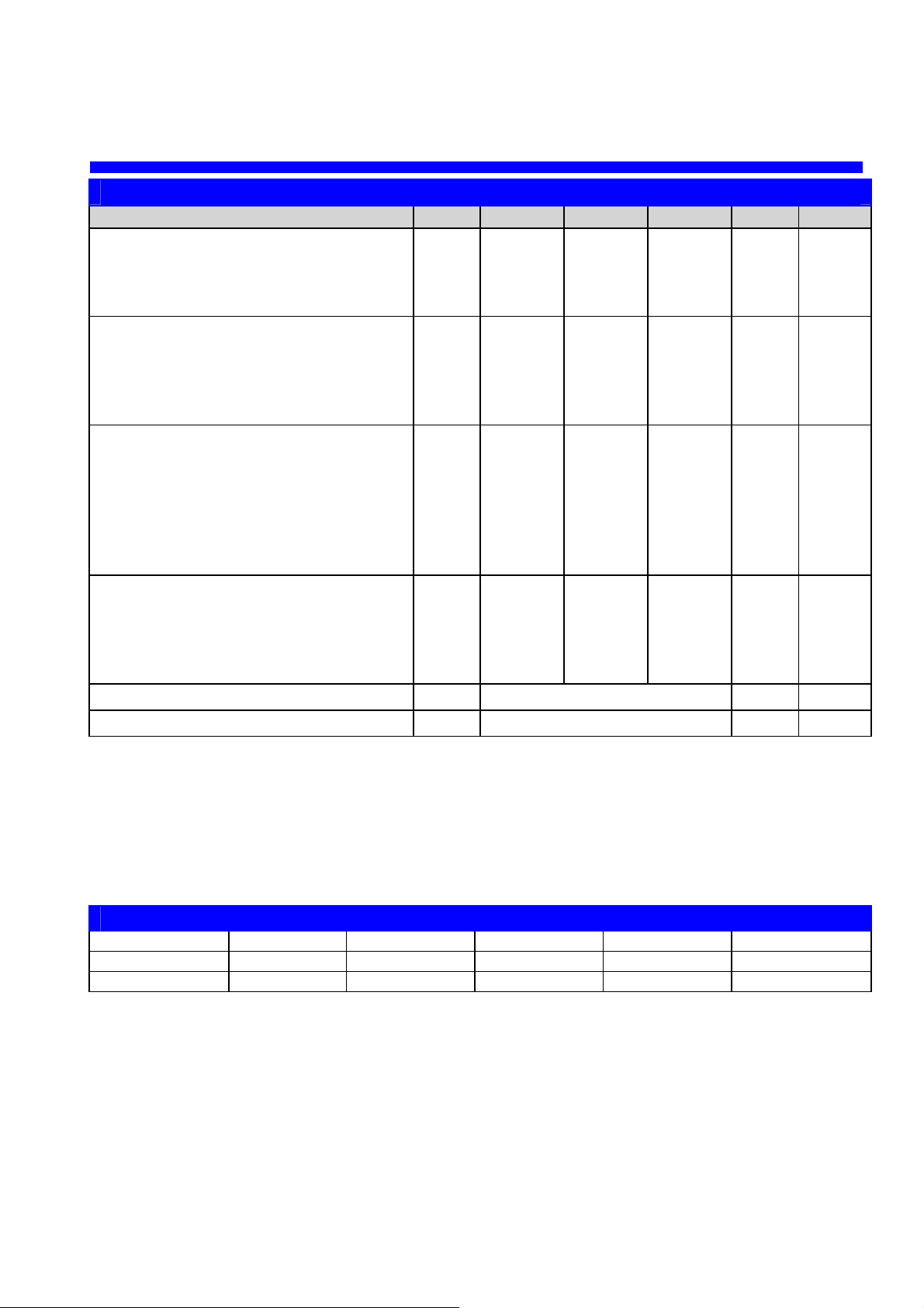
Table 1. Electrical Performance
Parameter Symbol Minimum Typical Maximum Units Notes
Frequency
Center Frequency FN 300 1350 MHz 1,2
Frequency Stability (Referenced to FO) F
STAB
+50, -250 ppm 1,2,7
Aging (10 years) +50, -100 ppm 5
Supply
Voltage (B) VCC 11.4 12 12.6 V 2,3
Voltage (C) VCC 4.75 5 5.25 V 2,3
Voltage (D) VCC 3.135 3.3 3.450 V 2,3
Current (No Load) ICC 55 70 mA 2,3
Output- Sinewave Options
Sinewave, into 50 Ώ (G) PO 0 dBm 2,3
Sinewave, into 50 Ώ (J) PO +7 dBm 2,3
Sinewave, into 50 Ώ (K) PO +10 dBm 2,3
Harmonics -20 dBc 2,3
Jitter @ 622.08 MHz (12 kHz to 20 MHz) 0.28 ps,rms 5,6
Jitter @ 622.08 MHz (50 kHz to 80 MHz) 0.29 ps,rms 5,6
Output- PECL Logic Option (F)
Output Level Low VOL VCC-1.95 VCC-1.63 V 2,3,4
Output Level High VOL VCC-0.98 VCC-0.75 V 2,3,4
Rise & Fall Time tR,tF 200 350 ps 2,3,4
Symmetry (Duty Cycle) SYM 45 49/51 55 % 2,3,4
Operating Temperature
TOP See Ordering Table ºC 1
Package Size
9.0 x 14.0 x 4.5 mm
Table Notes:
1. See Standard Frequencies and Ordering Information
2. Parameters are tested with production test circuit
3. Parameters are tested at ambient temperature with test limits guard-banded for specified operating temperature.
4. Output levels are standard 100K PECL compatible and measured from 20% to 80% of a full output swing (Fig 1).
5. Not tested in production, guaranteed by design, verified at qualification.
6. Integrated across 12 kHz to 20 MHz or 50 kHz to 80 MHz per GR-253-CORE Issue3.
7. Maximum Frequency occurs at room temperature
Table 2. Typical Single Side-Band Phase Noise (dBc/Hz) for Sinewave Output
Output Frequency 100 Hz Offset 1 kHz Offset 10 kHz Offset 100 kHz Offset 1 MHz Offset
622.08 MHz -70 -100 -125 -155 -160
1000 MHz -70 -100 -125 -155 -160
Page 3
SO-502 SAW Based Oscillator
Vectron International, 267 Lowell Rd, Hudson NH 03051-4916
Tel: 1-88-VECTRON-1
Website: www.vectron.com
3
Rev: 06June05
8.89±0.15
[0.350 ±0.006]
13.9 7±0.20
[0.550 ±0.008]
0.46±0.05
[0.018 ±0.002]
2.54±0 .13
[0.100 ±0.005]
5.08±0.13
[0.200± 0.005]
4.49
+0.20
-0.30
[
0.177
+0.00 8
-0.012
]
mm
[inch]
7.63
[0.300 ]
VS-500-LFF-GNN
XXX.XXX
VI YWW
1
4
3
625
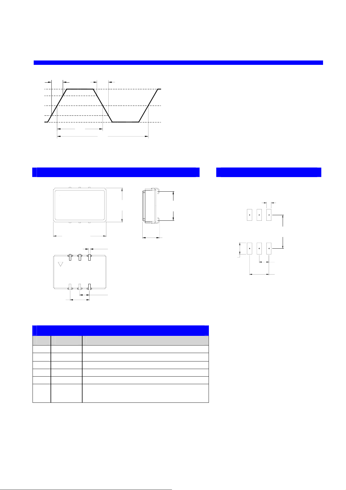
Outline Diagram Pad Layout
Table 3. Pin Out – PECL Option
Pin Symbol Function
1 - N/C
2 OD
N/C or Output Disable
1
3 GND Case and Electrical Ground
4 Output Output
5 COutput Complementary Output
6 VCC Power Supply Voltage
Table Notes:
1. By setting Output Disable pin low, the RF output is disabled and pin 4 is held high, pin 5 is held low.
The threshold for Output Disable is 1.4V above pin 3. Output disable pin can be left floating for normal operation
Figure 1. 100K PECL Waveform
Vcc - 1.6V
Vcc - 1.3V
Vcc - 1.0V
80%
20%
t
t
t
t
SYM = 100 x t
/
t
mm
[inch]
8.80
[0.346]
1.27
[0.050]
2.54
[0.100]
5.08
[0.200]
3.00
[0.118]
SO-502-BJF-GNN
XXX.XXX
∆ VI YYWW
Page 4

SO-502 SAW Based Oscillator
Vectron International, 267 Lowell Rd, Hudson NH 03051-4916
Tel: 1-88-VECTRON-1
Website: www.vectron.com
4
Rev: 06June05
Suggested Output Load Configurations – PECL Operation
4
5
Output
6
COutput
Vcc
Vc
1
OD
2
3
Gnd
+5.0V
120
Ω
120
Ω
82
Ω
82
Ω
.01uF
.1uF
+5.0V
+5.0V
(From P LL)
Vcc
COutput
Output
(From P LL)
OD
3
Gnd
2
4
5
Vc
1
6
330
Ω
330
Ω
.1uF
.01uF
+5.0V
(AC Coupling)
(AC Coupling)
Suggested Output Load Configurations – LVPECL Operation
4
5
Output
6
COutput
Vcc
Vc
1
OD
2
3
Gnd
+3.3V
130
Ω
130
Ω
82
Ω
82
Ω
.01uF
0.1uF
+3.3V
+3.3V
(From PLL)
Vcc
COutput
Output
(From PLL)
OD
3
Gnd
2
4
5
Vc
1
6
240
Ω
240
Ω
(AC Coupling)
(AC Coupling)
.01uF
0.1uF
+3.3V
Page 5

SO-502 SAW Based Oscillator
Vectron International, 267 Lowell Rd, Hudson NH 03051-4916
Tel: 1-88-VECTRON-1
Website: www.vectron.com
5
Rev: 06June05
Table 4. Pin Out – Sinewave Option
Pin Symbol Function
1 VC
N/C
2 - N/C
3 VEE Ground
4 Output Sinewave Output
5 VCC Vcc21
6 VCC
Vcc1
Table Notes:
1. If Vcc1 is +12V and a separate 5V is not applied to pin 5 then pin 5 must be connected through a 220Ώ 1/4W external resistor.
Suggested Output Load Configurations – SINEWAVE Operation
+5V
Vcc
0.01uF
0.01uF
27 Ώ
1/8 W
NC
NC
Output AC Coupled with
50 Ώ to ground
0.1uF
2
6
5
+12V
Vcc
0.01uF
0.01uF
220 Ώ
1/4W
NC
Output AC Coupled with
50 Ώ to ground
0.1uF
2
6
5
Page 6

SO-502 SAW Based Oscillator
Vectron International, 267 Lowell Rd, Hudson NH 03051-4916
Tel: 1-88-VECTRON-1
Website: www.vectron.com
6
Rev: 06June05
Tape and Reel (EIA-481-2-A)
Tape Dimensions (mm) Reel Dimensions (mm)
Dimension W F Do Po P1 A B C D N W1 W2 # Per
Tolerance Typ Typ Typ Typ Typ Typ Min Typ Min Min Typ Max
Reel
SO-502 24 11.5 1.5 4 12 330 1.5 13 20.2 100 24.4 30.4 200
Absolute Maximum Ratings
Parameter Symbol Ratings Unit
Power Supply
V
CC
V
CC
+ 1.0V
V
Storage Temperature TS
-55 to +125
°C
Soldering Temp/Time
T
LS
+220/10
°C/sec
Stresses in excess of the absolute maximum ratings can permanently damage the device. Functional operation
is not implied at these or any other conditions in excess of conditions represented in the operational sections of
this datasheet. Exposure to absolute maximum ratings for extended periods may adversely affect device
reliability.
Reliability
The SO-502 family is capable of meeting the following qualification tests:
Environmental Compliance
Parameter Conditions
Mechanical Shock MIL-STD-883, Method 2002
Mechanical Vibration MIL-STD-883, Method 2007
Solderability MIL-STD-883, Method 2003
Gross and Fine Leak MIL-STD-883, Method 1014
Resistance to Solvents MIL-STD-883, Method 2016
Po
W
A
N
F
P1
W1
W2
C
B
D
ØDo
Page 7

SO-502 SAW Based Oscillator
Vectron International, 267 Lowell Rd, Hudson NH 03051-4916
Tel: 1-88-VECTRON-1
Website: www.vectron.com
7
Rev: 06June05
Handling Precautions
Although ESD protection circuitry has been designed into the SO-502 proper precautions should be taken when
handling and mounting. VI employs a human body model and a charged-device model (CDM) for ESD
susceptibility testing and design protection evaluation.
ESD Ratings
Model Minimum Conditions
Human Body Model 1500 V MIL-STD 883, Method 3015
Charged Device Model 1000 V JESD 22-C101
Recommended Solder Reflow Profile
VI qualification includes aging at various extreme temperatures, shock and vibration, temperature cycling, and IR
reflow simulation. The conditions a device can withstand are well understood and devices can be subjected to
the profile above. This profile shows a ramp up condition to prevent thermal shock, a preheat period in which the
flux is activated, a ramp up to 183°C which is the reflow temperature of Sn/Pb eutectic, and a gradual cool down.
The time above 183°C should not exceed 60 seconds and the peak temperature should be no more than 220°C
for 10 seconds. The SO-502’s are hermetically sealed so an aqueous wash is not an issue.
60 60-90
45-60
150
183
220
Time (s)
Temperature (Deg C)
Page 8

SO-502 SAW Based Oscillator
Vectron International, 267 Lowell Rd, Hudson NH 03051-4916
Tel: 1-88-VECTRON-1
Website: www.vectron.com
8
Rev: 06June05
Available Standard Frequencies (MHz)
480 622.08 640 938 970 983.04
990 1000 1090 1200 1330
Other Frequencies Available Upon Request.
Ordering Information
SO – 502 - B J C - G N N – xxxx.xxxx
For Additional Information, Please Contact:
Vectron International reserves the right to make changes to the product(s) and or information contained herein without notice.
No liability is assumed as a result of their use or application. No rights under any patent accompany the sale of any such product(s) or information.
Product Family
SO: SAW XO
Package
502: 9 x 14 x 4.5 mm
Input
D: 3.3 V
C: 5.0 V
B: 12.0 V
Output
F: PECL
G: Sine ≥ 0 dBm
H: Sine ≥ 3 dBm
J: Sine ≥ 7 dBm
K: Sine ≥ 10 dBm
Operating Temperature
C: 0°°°°C to +70 °°°°C
D: -20°°°°C to +85 °°°°C
-
°°°°
+
°°°°
Other (Future Use)
N: N/A
Other (Future Use)
N: N/A
Frequency Stability
L: ± 130 ppm (0°°°°C to +70 °°°°C only)
T: ± 200 ppm
Frequency (See Above)
300 – 1350 MHz
USA: Vectron International, 267 Lowell Rd, Hudson, NH 03051 . . . . Tel: 1-88-VECTRON-1 Fax: 1-888-FAX-VECTRON
EUROPE: . . . . . . . . . . . . . . . . . . . . . . . . . . . . . . . . . . . . . . . . . . . . . Tel: +49 (0) 3328-4784-17 Fax: +49 (0) 3328-4784-30
ASIA: . . . . . . . . . . . . . . . . . . . . . . . . . . . . . . . . . . . . . . . . . . . . . . . . . Tel: +86-21-28909740 Fax: +86-21-28909999
 Loading...