

Page 1
查询RXM-115A供应商
Product Data Sheet
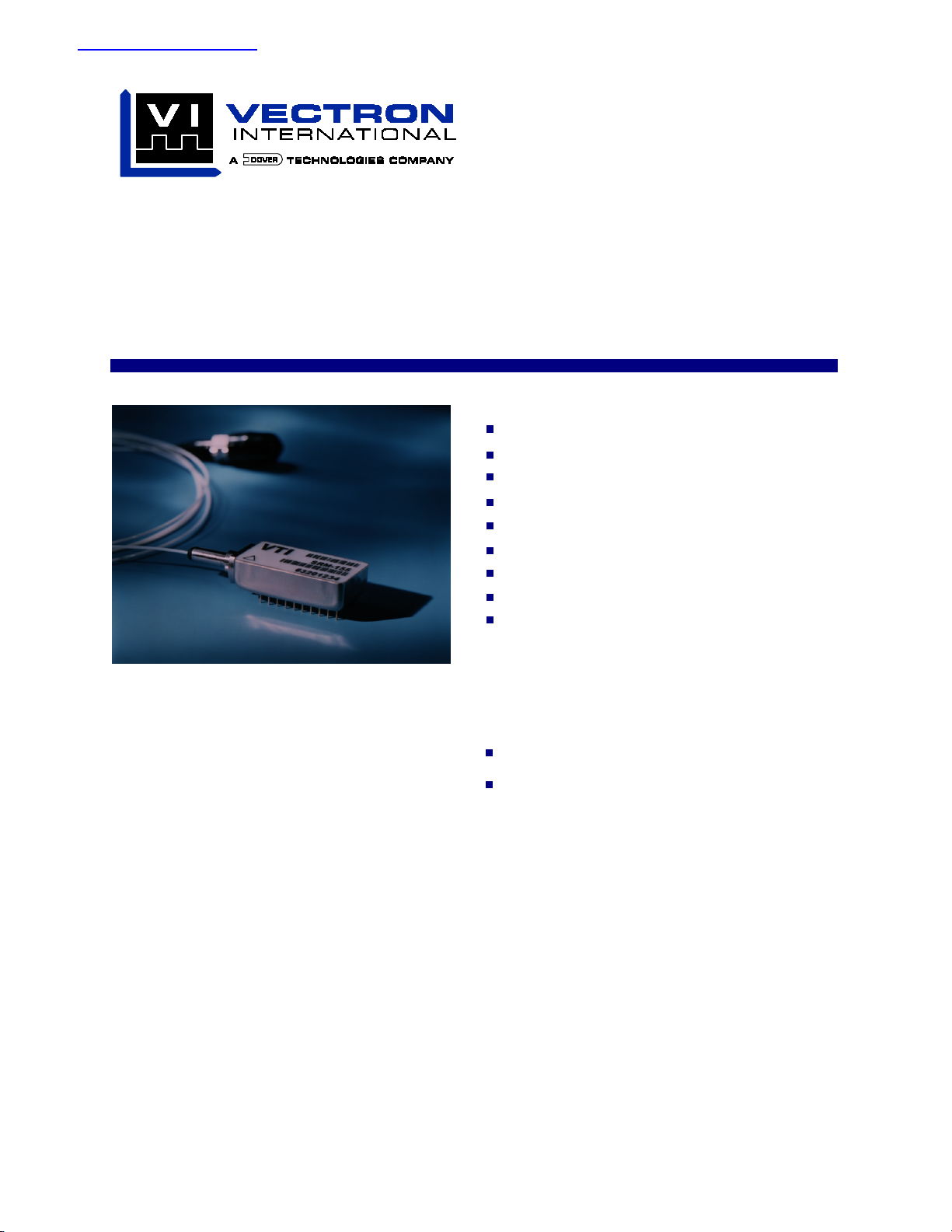
RXM-155
SONET/SDH Fiber-Optic Receiver Module
Features
SONET OC-3 and SDH STM-1 Compatible
PECL Data Outputs
Single +5 Volt Supply
PECL Loss of Signal Flag
Operation at 1300 nm and 1550 nm
-45° to +85°C Operation
-34dBm minimum sensitivity
Wide Dynamic Range
Multi-Sourced 20 Pin DIL Footprint
The RXM-155 SONET/SDH Fiber-Optic Receiver Module
Applications
Telecom Receiver Applications
Medium and Long Haul SONET/SDH @ 155 Mb/s
High Performance Datacom Receiver Applications
ATM @ 155 Mb/s
Description
VI’s RXM-155 is an integrated fiber-optic receiver
module. It is powered by a single +5v power supply and
is housed in a 20 PiN DIL package.It is ideally suited for
SONET OC-3, SDH STM-1 and other 155 Mb/s fiberoptic transmission applications that demand superior
performance. It is available with a multi-mode fiber
pigtail with either FC/PC,ST or SC connector.
Vectron International 166 Glover Avenue Norwalk CT. 06856-5160 Tel: 1-88-VECTRON-1 www.vectron.com
Page 2
RXM-155 SONET/SDH Receiver Module
Product Data Sheet
Functional Overview
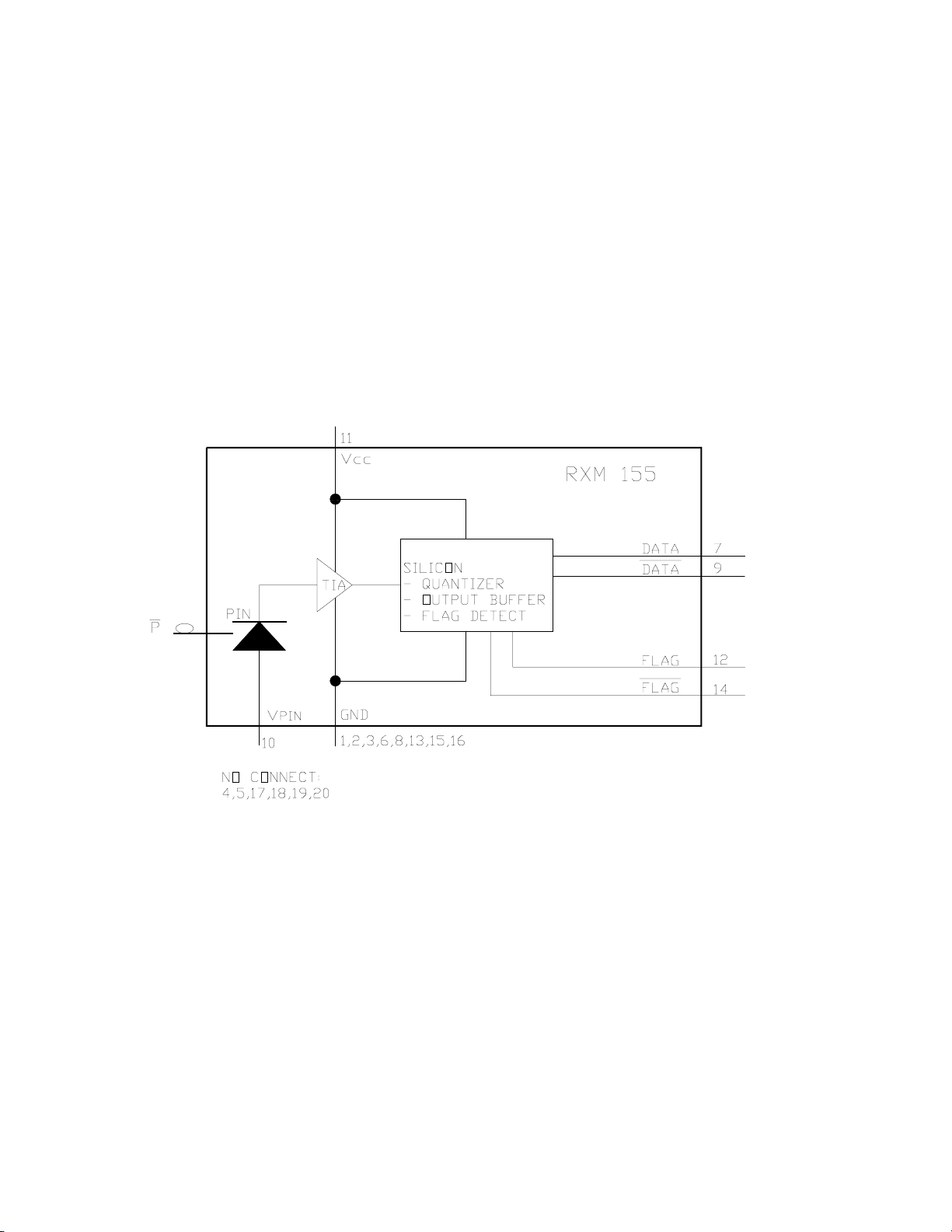
This highly integrated module converts a 155 Mb/s
fiber-optic NRZ signal to differential PECL data outputs.
A PECL flag alerts the user to a loss of signal condition
when the optical input falls below an acceptable level.
A single +5 Volt supply provides bias for the module’s
preamplifier, and Quantizer. The photodiode may be
biased with -5 Volts or Grounded. All elements are
integrated into fiber-coupled 1.3” X 0.635” 20 pin DIL
package. The RXM-155 footprint and pinout are
industry common for ease of integration.
The optical signal is coupled through a short length of
50.0 µm multimode or single mode optical fiber to a
hermetic module which encases an InGaAs PiNphotodiode and preamplifier. The PiN-photodiode
converts the optical signal to an electrical current. The
signal is then converted to a voltage and amplified by a
low noise transimpedance amplifier.
Further gain is provided by the quantizer, which also
provides a Flag output when the optical signal falls
below an acceptable level.
Figure 1. RXM-155 Functional Block Diagram
Vectron International 166 Glover Avenue Norwalk CT. 06856-5160 Tel: 1-88-VECTRON-1 www.vectron.com
2
Page 3
RXM-155 SONET/SDH Receiver Module
Product Data Sheet
10
Pin 1 Indicator
Top View
11
20
Figure 2. Pin Diagram (Top View)
Table 1. Pin Function
Pin
7 Data PECL Data Output.
9 Data PECL Complementary Data Output.
10 V
11 V
12 Flag Input Signal Level Status. This PECL output switches low when the received
14 Flag Complementary Input Signal Status. PECL complement of Flag.
1,2,3,6,8,13,15,16 GND Ground.
4,5,17,18,19,20 NC No User Connection.
1. By connecting pin 10 to a -5 Volt bias through a series resistor (e.g. 1 kΩ) received optical power can be monitored as a voltage drop across the resistor.
Symbol
D
CC
Function
Detector Anode Bias. Connect to GND or a -5V biased series resistor for
received optical power monitoring.
5 Volt Supply Voltage.
optical power falls below the flag threshold.
1
Absolute Maximum Ratings
Absolute maximum ratings are provided here as
worst case and short duration exposure conditions
only. Exposure to conditions more severe than the
Absolute Maximum Ratings may result in permanent
damage. Exposure to conditions at the Absolute
Table 2. Absolute Maximum Ratings
Parameter Symbol Minimum Maximum Units
Storage Temperature Range T
Supply Voltage V
pin Detector Bias V
Lead Soldering Conditions 250/10 °C/s
Vectron International 166 Glover Avenue Norwalk CT. 06856-5160 Tel: 1-88-VECTRON-1 www.vectron.com
S
CC
D
Maximum Ratings for extended periods may also
adversely affect device performance or reliability.
Functional operation of the device is not implied at
these conditions.
-40 85 °C
0+6V
-15 0 V
3
Page 4

RXM-155 SONET/SDH Receiver Module
Product Data Sheet
Performance Characteristics
Table 3. Electrical Performance
Parameter Symbol Minimum Typical Maximum Units
Input Signal Rate f
Operating Temperature T
Power Supply Voltage V
pin Detector Bias Voltage (pin10) V
Power Supply Current I
Data Output Levels
1
Low
High
Data Output Rise and Fall Times
Received Power Level Flag
2
T
LOS
Decreasing Optical Power
Increasing Optical Power
O
CC
CC
V
OL
V
OH
R, TF
O
D
120 155.52 175 Mb/s
-40 +85 °C
4.5 5.0 5.5 V
-15 0 0 V
200 mA
V
- 1.95
CC
VCC - 1.03
VCC - 1.63
V
- 0.88
CC
275 375 575 ps
-37
-35
V
V
dBm
dBm
Flag Hysteresis Hyst 2 dB
1. Measured with a load of RL = 50Ω to VCC - 2 V. See figures 3 and 4. ECL levels are specified for dc measurement, an additional tolerance of 50 mV should be included for
dynamic measurements.
2. Measured at 20% to 80% levels.
Figure 3. PECL Interface
Vectron International 166 Glover Avenue Norwalk CT. 06856-5160 Tel: 1-88-VECTRON-1 www.vectron.com
4
Page 5

RXM-155 SONET/SDH Receiver Module
Product Data Sheet
Figure 4. ECL (AC Coupled) Interface
Figure 5. Typical Performance @ 155.52MHz
Table 4. Optical Performance
Parameter Symbol Minimum Typical Maximum Units
Minimum Average Sensitivity
Maximum Optical Input
Input Wavelength
1. For a BER less than 1E-10. Measured using a 223 - 1 pseudorandom word and a 50% average optical duty cycle and a 10 dB Extinction Ratio.
Vectron International 166 Glover Avenue Norwalk CT. 06856-5160 Tel: 1-88-VECTRON-1 www.vectron.com
1
Sens. -34.0 dBm
1
P
MAX
λ
1280 1580 nm
0dBm
5
Page 6

RXM-155 SONET/SDH Receiver Module
Product Data Sheet
Qualification
The RXM-155 has been designed to comply with the
requirements of Bellcore specifications GR-468CORE, Reliability Assurance for Optoelectronic
devices and will be subject to a complete qualification
test plan to demonstrate full compliance. All of the
technologies used in the assembly of the module
represent standard microelectronic and optical
technologies that are used in similar products, and
have extensive field reliability data.
All components and technologies used in the optical
receiver are backed by qualification data covering
mechanical and environmental tests along with
accelerated life tests. Typical tests, test conditions
and sample sizes are listed below.
Table 5. Qualification Plan
Test Test Method Sample Size
Physical Dimensions MIL-STD-883, Method 2016 11
Mechanical Shock MIL-STD-883, Method2002, Test B 11
Vibration, variable frequency MIL-STD-883, Method 2007, Test A 11
Lead Solderability MIL-STD-883, Method 2003 22 Leeds
Lead Integrity MIL-STD-883, Method 2004 15 Leeds
Temperature Cycling -40°C/85°C, 300 cycles 11
High Temperature Aging 85°C under bias, 2000 hours 11
Damp Bake 85°C/85% RH/ 1000 hrs 11
Low Temperature Storage -40°C, 168 hours 11
ESD MIL-STD-883,Method 3015 3
Destructive Bond Pull MIL-STD-883,Method 2011 40
Table 6. Optical Fiber Characteristics
Parameter Minimum Typical Maximum Units
Fiber Length 1000 mm
Fiber Core 50 um
Fiber Buffer 900
Vectron International 166 Glover Avenue Norwalk CT. 06856-5160 Tel: 1-88-VECTRON-1 www.vectron.com
µ
m
6
Page 7

RXM-155 SONET/SDH Receiver Module
7
Product Data Sheet
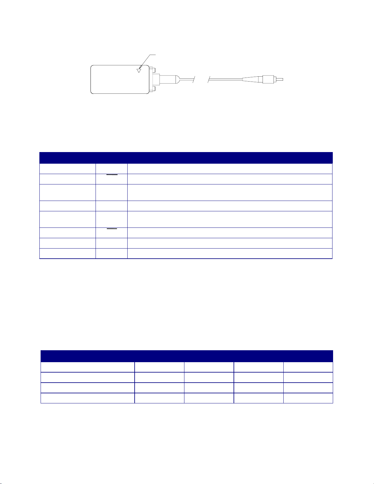
Outline Diagram
Figure 6. Outline Diagram
Ordering Information
Standard modules are built with 50um MM fiber, with an outer jacket diameter of 900um. Alternative fiber type,
connector type and fiber lengths are available upon request. Contact factory for specific details.
Table 7. Part Numbers
Fiber-Optic Connector
FC/PC RXM-155A 330018265
ST RXM-155B 330003674
SC RXM-155C 330018276
1. Other connectors or fiber requirements are available to meet specific application requirements.
Vectron International 166 Glover Avenue Norwalk CT. 06856-5160 Tel: 1-88-VECTRON-1 www.vectron.com
1
Model Number VI Code Number
Page 8

RXM-155 SONET/SDH Receiver Module
8
Product Data Sheet
Notes:
Vectron International • 166 Glover Avenue, Norwalk, CT 06856 • Tel: 1-88-VECTRON-1 • Fax: 1-888-FAX-VECTRON
USA:
In Denmark, Finland, Ireland, Italy, Israel, Norway, Spain, UK: Tel: 44 (0) 1703 766 288 • Fax: 44 (0) 1703 766 822
EUROPE:
In Austria,Belgium,France,Germany,Luxenburg,Netherlands,Sweden,Switzerland:Tel: 49(0)7263 6480 • Fax:49(0)7263 6196
In China, Taiwan, Japan: Tel: 01 603 598 0070 • Fax: 01 603 598 0075
ASIA:
In Korea, Singapore, Australia, India: Tel: 01 203 853 4433 • Fax: 01 203 853 1423
Vectron International, Inc. reserves the right to make changes to the product(s) and/or information contained herein without notice. No liability is
assumed as a result of their use or application. No rights under any patent accompany the sale of any such product(s) or information.
Vectron International 166 Glover Avenue Norwalk CT. 06856-5160 Tel: 1-88-VECTRON-1 www.vectron.com
 Loading...