

Page 1
VECTRON SYSTEMS
POS Touch 12
POS Touch 12 II PCT
User manual
Page 2

Page 3

Your Vectron dealer
Stamp
Date: 2017-02-03
© 2017 by Vectron Systems AG
Subject to error and technical modification
Manufacturer
Vectron Systems AG
Willy-Brandt-Weg 41
48155 Muenster, Germany
www.vectron-systems.com
Vectron
Leading in POS Technology
3
Page 4

Page 5

Contents
1. Important information ......................................................... 9
1.1. Target group of this user manual ............................................... 9
1.2. Dealer support .............................................................................. 9
1.3. Scope of delivery ........................................................................ 10
2. Terms, signs and signals ...................................................11
2.1. Safety-related information ........................................................ 11
2.1.1. Warnings ...................................................................................... 11
2.1.2. Warning symbol ..........................................................................11
2.1.3. Signal words ................................................................................ 12
2.2. Notes ............................................................................................ 12
3. Notes on safety .................................................................. 13
4. Device description .............................................................15
4.1. Intended use ................................................................................ 15
4.2. POS Touch 12 POS system ........................................................ 16
4.2.1. Front view .................................................................................... 16
4.2. 2. Rear view ..................................................................................... 17
4.2.3. Ports and interfaces................................................................... 18
4.2.4. Dimensions incl. foot S420 (in mm and inch) ......................... 19
4.2.5. Dimensions incl. foot S500 (in mm and inch) ......................... 20
4.2.6. Dimensions incl. wall mount (in mm and inch)........................21
4.3. Power supply PS60 .................................................................... 22
4.4. Power supply PS61 ..................................................................... 23
4.5. Mains cable .................................................................................. 24
4.6. Vectron POS software ................................................................ 24
5. Technical data .................................................................... 25
5.1. POS Touch 12 POS system ........................................................ 25
5.2. POS Touch 12 II PCT POS system ............................................. 26
5.3. Power supply Vectron PS60 or PS 61...................................... 28
5.4. Vectron POS software (POS Touch 12)....................................29
5.5. Vectron POS software (POS Touch 12 II PCT) ........................ 29
6. Starting ............................................................................... 31
5
Page 6

POS TOUCH 12
POS TOUCH 12 II PCT
6.1. POS Touch 12 set up .................................................................. 31
6.1.1. Selecting the setup site for POS Touch 12 ............................. 31
6.1.2. Connecting the POS Touch 12 to the power supply ............... 32
6.1.3. Connecting devices to the POS Touch 12 ............................... 32
6.2. Aligning the screen .................................................................... 33
7. Operation ............................................................................34
7.1. Switching on and off the POS Touch 12 ..................................34
7.1.1. Switching on the POS Touch 12 ................................................ 34
7.1.2. Switching off the POS Touch 12 ............................................... 35
7.1.3. POS Touch 12 reboot ................................................................. 35
7.2. User interface .............................................................................36
7.2.1. Registration surface................................................................... 37
7.2.2. Payment interface ...................................................................... 39
7.3. Sign in/out at POS Touch 12 .....................................................40
7.3.1. Sign in via operator button ....................................................... 40
7.3.2. Sign in via operator key ............................................................. 41
7.4. Working with guest checks (GC) ............................................... 42
7.4.1. Opening a guest check ............................................................... 42
7.4.2. Booking PLUs to a GC ................................................................. 43
7.4.3. Closing a GC ................................................................................43
7.4.4. Finalizing a GC ............................................................................44
7.4.5. Separate invoicing of groups or single persons ..................... 45
7.4.6. Splitting single PLUs to another guest check .........................46
7.4.7. Moving all PLUs to another guest check ................................. 47
7.4.8. Transferring a GC to another operator .................................... 47
7.5. Working with hold buffers ......................................................... 48
7.6. Working with reports .................................................................48
7.7. Correction or void last entry .................................................... 48
7.8. Print data server ........................................................................49
8. Service and maintenance ..................................................50
8.1. Cleaning ....................................................................................... 50
8.2. Contacting the customer service ............................................. 51
9. Errors, possible reasons and troubleshooting ................ 52
10. Shutdown ............................................................................ 55
11. Disposal ..............................................................................56
6
Page 7

12. Glossary ..............................................................................57
13. Icons ....................................................................................59
14. EU Declaration of Conformity ........................................... 64
15. Accessories ........................................................................65
15.1. Operator lock systems ............................................................... 65
15.1.1. Operator lock L10 T15/T12 ...................................................... 65
15.1.2. Operator lock L21 T15/T12 ......................................................66
15.1.3. Operator lock L30 T15/T12 ...................................................... 66
15.1.4. Operator lock Vectron L10 ........................................................ 67
15.1.5. Operator lock Vectron L21 ...................................................... 67
15.1.6. Operator lock Vectron L30 ....................................................... 67
15.2. Customer displays ......................................................................68
15.2.1. Customer display Vectron C56 ................................................. 68
15.2.2. Customer display Vectron C75 ................................................. 69
15.2.3. Customer display Vectron C100 ............................................... 70
15.3. Extension cable Vectron PS60 ................................................. 71
15.4. Stylus ...........................................................................................71
15.4.1. Vectron stylus ............................................................................. 71
15.4.2. Multifunction stylus ...................................................................72
15.4.3. Touchpen Vectron PCT .............................................................. 72
16. Other Vectron products ....................................................73
16.1. Stationary Vectron POS systems ............................................. 73
16.1.1. Vectron POS Touch 15, POS Touch 15 PCT,
POS Touch 15 II PCT .................................................................. 74
16.1.2. Vectron POS Vario II .................................................................. 75
16.1.3. Vectron POS Mini II .................................................................... 76
16.2. Mobile Vectron POS systems ....................................................77
16.2.1. Vectron POS MobilePro III .........................................................77
16.3. Software ...................................................................................... 78
16.3.1. Vectron Mobile App .................................................................... 78
16.3.2. Vectron Commander .................................................................. 79
16.3.3. Vectron Journal Tool .................................................................80
16.3.4. Vectron POS PC .......................................................................... 80
16.4. bo nVito .........................................................................................80
7
Page 8

Page 9

1. Important information
This user manual is part of the
• POS Touch 12
or
• POS Touch 12 II PCT,
hereinafter called POS Touch 12.
Please read the whole document and in particular the chapter "Notes
on safety" before working with the product. Keep the document so
that it is available for all users at any time. Always enclose the required documents when forwarding the product to others.
1.1. Target group of this user manual
End users of the POS Touch 12.
1.2. Dealer support
Your specialist retailer has programmed the POS Touch 12
for you and is your contact partner for questions concerning
the programming. If necessary, he will be glad to support you
during initial start-up and will train you in using your POS
system.
9
Page 10

POS TOUCH 12
POS TOUCH 12 II PCT
1.3. Scope of delivery
Standard shipment
Optional
accessories
Vec t ron POS
Touch 12
(with foot
S400)
Vec tro n P OS
Touch 12 POS
system incl.
foot S400
Housing Touch
12 port cover
foot
Power supply
Vectron P S60
Operator lock Vectron L10 with four operator
keys
Two covers each for the SD-card- and SIMcard slot
Power cord
Vectron POS software with licence
Notes on safety and installation
Dispatch box
Operator lock Vectron L21, Vectron L30
Customer display Vectron C56, Vectron C75,
Vec tron C100
Vec t ron POS
Touch 12
(with foot
S500)
Vec tro n P OS
Touch 12 POS
system incl.
foot S500
Housing Touch
12 port cover
foot
Power supply
Vectron P S61
Vec t ron POS
Touch 12
(with wall
mount)
Vec tro n P OS
Touch 12 POS
system incl.
wall mount
Housing Touch
12 port cover
wall mount
Power supply
Vectron P S61
10
Page 11

2. Terms, signs and signals
2.1. Safety-related information
These instructions contain introductory safety information
and specific warnings for your POS Touch 12 system .
2.1.1. Warnings
A SIGNAL WORD
Type and source of danger. Consequence of
non-compliance
X
Averting of a danger
a
2.1.2. Warning symbol
Warning sym-
bol
A A
a
q
s
Meaning
Warning symbols for instructions warning of
injuries.
General warning symbol.
Warning symbol for hazards due to
crushing.
Warning symbol for hazards due to electric
shock.
11
Page 12

POS TOUCH 12
POS TOUCH 12 II PCT
2.1.3. Signal words
The signal word „DANGER“ indicates a danger with high risk,
which will result in death or severe injury if it is not avoided.
The signal word „WARNING“ indicates a danger with medium
risk, which could result in death or severe injury if it is not
avoided.
The signal word „CAUTION“ indicates a danger with low risk,
which could result in minor injuries if it is not avoided.
A DANGER
A WARNING
A CAUTION
NOTICE
12
The signal word „NOTICE“ indicates a danger which could
result in material damage if it is not avoided.
2.2. Notes
This sign refers to information that can be
helpful when operating your POS Touch 12.
i
Page 13

3. Notes on safety
A DANGER
Deadly shock caused by damaged POS system components.
X
Disconnect the mains cable from the power grid in case of
damage. Contact your Vectron specialist retailer if POS
system components are damaged.
A CAUTION
Pinching of fingers when aligning the screen.
The gap between the screen housing and the joint changes
during alignment.
X
Do not insert your fingers between the screen housing and
the joint.Before aligning the screen see the notes in chapter
6.2 “Aligning the screen” on page 33.
Risk of stumbling and damaging the POS system components by
device cables lying unprotected in the room.
X
Route the device cables so that they do not pose a potential
hazard!
13
Page 14

POS TOUCH 12
POS TOUCH 12 II PCT
Damage of POS system components caused by excessively high
voltages or currents.
X
Use an earthed socket to which alternating current between
110 and 240 volts is connected.
X
Use power sources which are protected with a residualcurrent circuit breaker.
Malfunctions caused by faulty programming.
X
Only change the programming when your are absolutely sure
of the effects this will have.
X
Protect the programming and programming functions with
passwords.
X
Your Vectron specialist retailer will support you should you
have questions on programming or will program the POS
system according to your requirements.
Damage of touch screen caused by unsuitable objects.
X
Please touch the screen exclusively with fingers or the
provided stylus.
NOTICE
14
Burn-in effect through static image content.
Shadow images can remain visible on the display due to static
image content.
X
Please configure the screen saver.
X
Your Vectron dealer will support you should you have
questions on programming or will program the POS system
according to your requirements.
Aggressive cleansers can damage the housing surface.
X
Do not use any scouring or dissolving agents for cleaning.
X
If necessary clean the housing surface with a smooth, lintfree cloth. In case of strong contamination you can dampen
the cloth with water or with a mild, residue-free cleanser.
Damage to POS system components when transporting in
unsuitable packing.
X
Dispatch the POS system components exclusively in the
original packing.
Page 15

4. Device description
4.1. Intended use
The POS Touch 12 is a mobile POS system for order taking
and payment.
The POS Touch 12 may be used under ambient conditions
as defined in chapter 5 “Technical data” on page 25. To
operate the POS Touch 12 use exclusively Vectron original
accessories or Vectron-approved accessories.
The Vectron Systems AG does not accept liability for damages
or injuries resulting from improper use.
The operating company of the POS Touch 12 is responsible
for saving and backup of data that was created with the
POS Touch 12.
The operating company of the POS Touch 12 is responsible for
processing the data in accordance with the legal demands.
15
Page 16

POS TOUCH 12
POS TOUCH 12 II PCT
4.2. POS Touch 12 POS system
4.2.1. Front view
1
2
3
16
Fig. 1: POS Touch 12 front view
Pos. Designation Description
1 Touchscreen Data input with stylus or fingers
2 Operator lock Log in/out with operator key.
3 two USB ports Port for external devices and stor-
age media.
Page 17
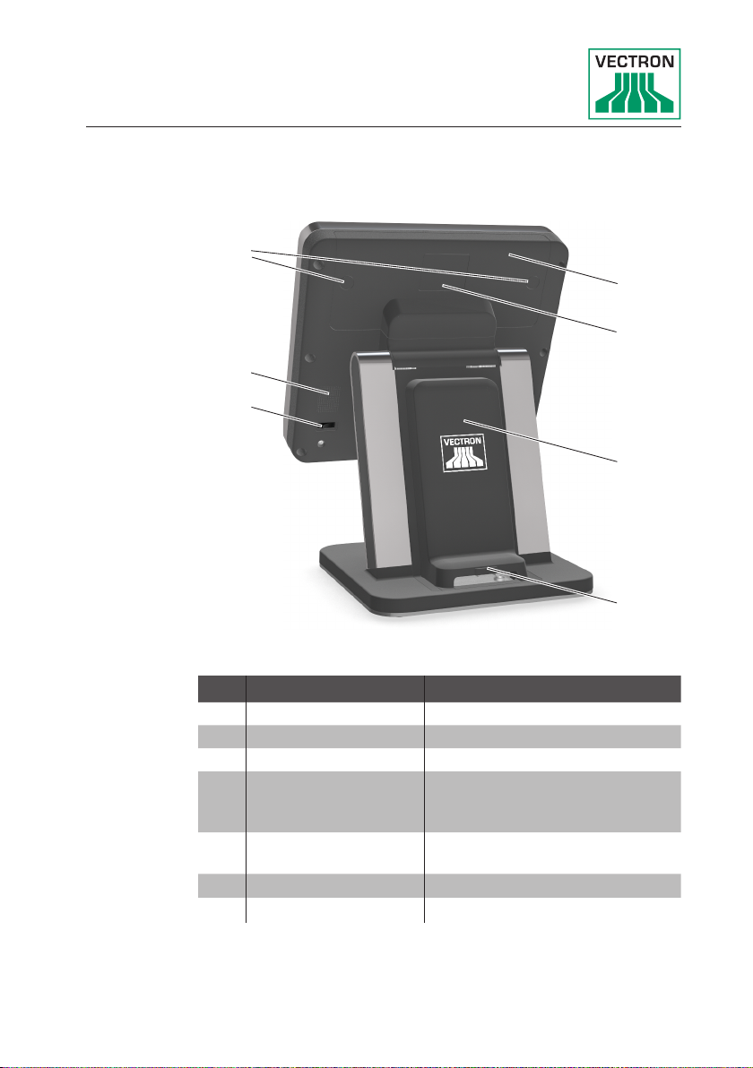
4.2.2. Rear view
3
2
1
Pos. Designation Description
1 On/Off key
2 Loudspeaker
3 Port cover locking
4 Port cover Cover for ports and interfaces
5 Customer display
port cover
6 Foot cover Cover for power supply.
7 Foot cover locking
4
5
6
7
Fig. 2: Rear view
(see in chapter 4.2.3 “Ports
and interfaces” on page 18).
This cover can be removed to
connect a customer display.
17
Page 18

POS TOUCH 12
POS TOUCH 12 II PCT
4.2.3. Ports and interfaces
Pos. Designation Description
1 USB ports Six USB 2.0 ports for external
2 Network Network port, RJ45, 10/100
3 SIM card slot For standard Mini SIM cards (25
4 Serial interfaces Six Serial interfaces for external
5 Card interface Slot for SD and SDHC memory
6 Audio port Port for stereo loudspeakers.
7 Power connec-
tion
8 Drawer connec-
tion
4 5 8721 3 6
Fig. 3: Ports and interfaces
devices and storage media.
BaseT.
x 15mm).
devices, RJ45.
cards.
Port for power supply PS61.
Two ports for cash drawers.
18
Page 19

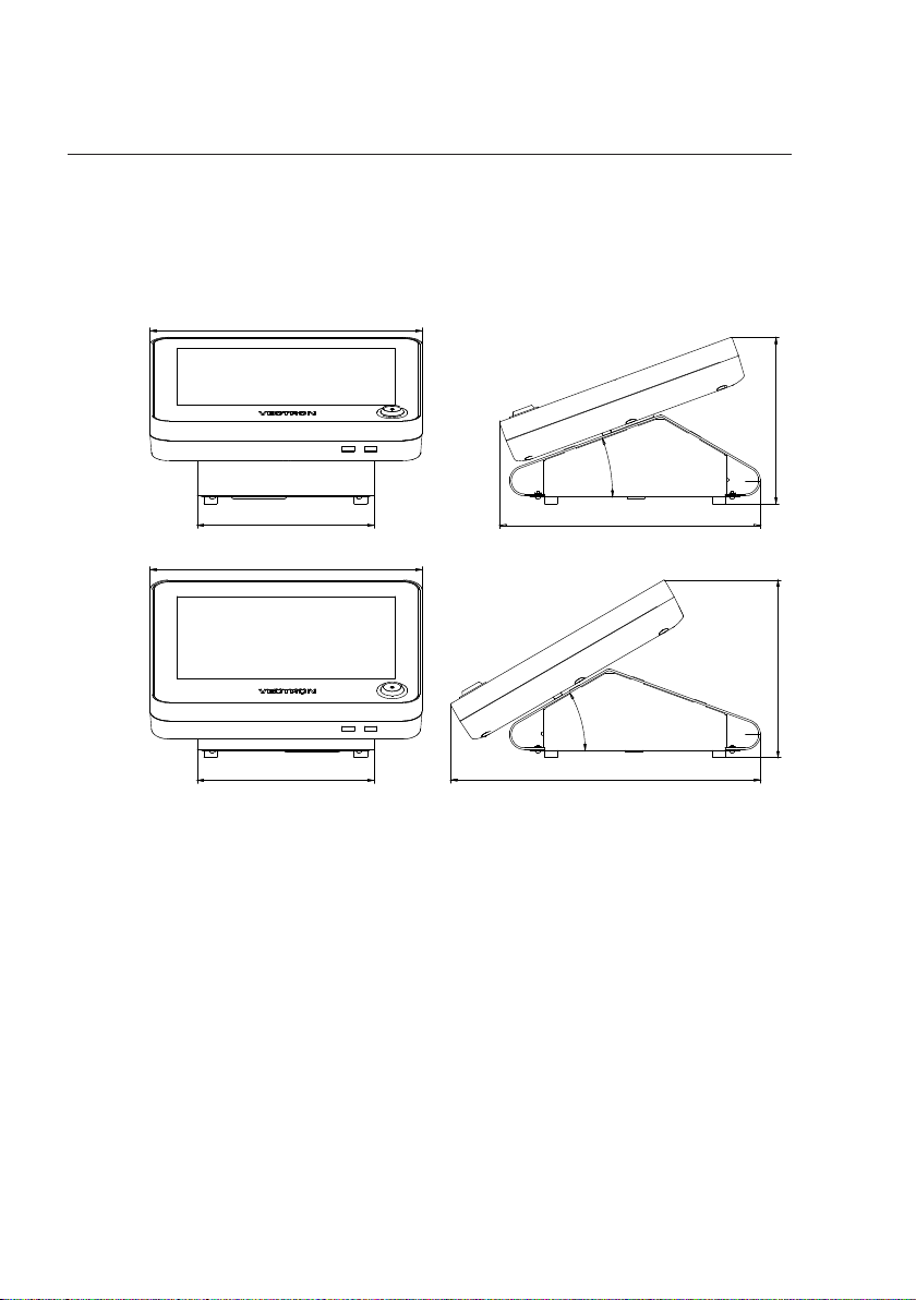
4.2.4. Dimensions incl. foot S420 (in mm and inch)
250
(9.8")
308
(12.1")
396
(15.6")
250
(9.8")
270
(10.6")
388
(15.3")
316
(12.4")
Fig. 4: POS Touch 12 Dimensions incl. foot S420 (in mm and inch)
19
Page 20
POS TOUCH 12
187
(7.4")
308
(12.1")
200
(7.9")
200
(7.9")
200
(7.9")
295
(11.6")
351
(13.8")
308
(12.1")
30°
20°
POS TOUCH 12 II PCT
4.2.5. Dimensions incl. foot S500 (in mm and inch)
20
Fig. 5: POS Touch 12 Dimensions incl. foot S500
(in mm and inch)
Page 21
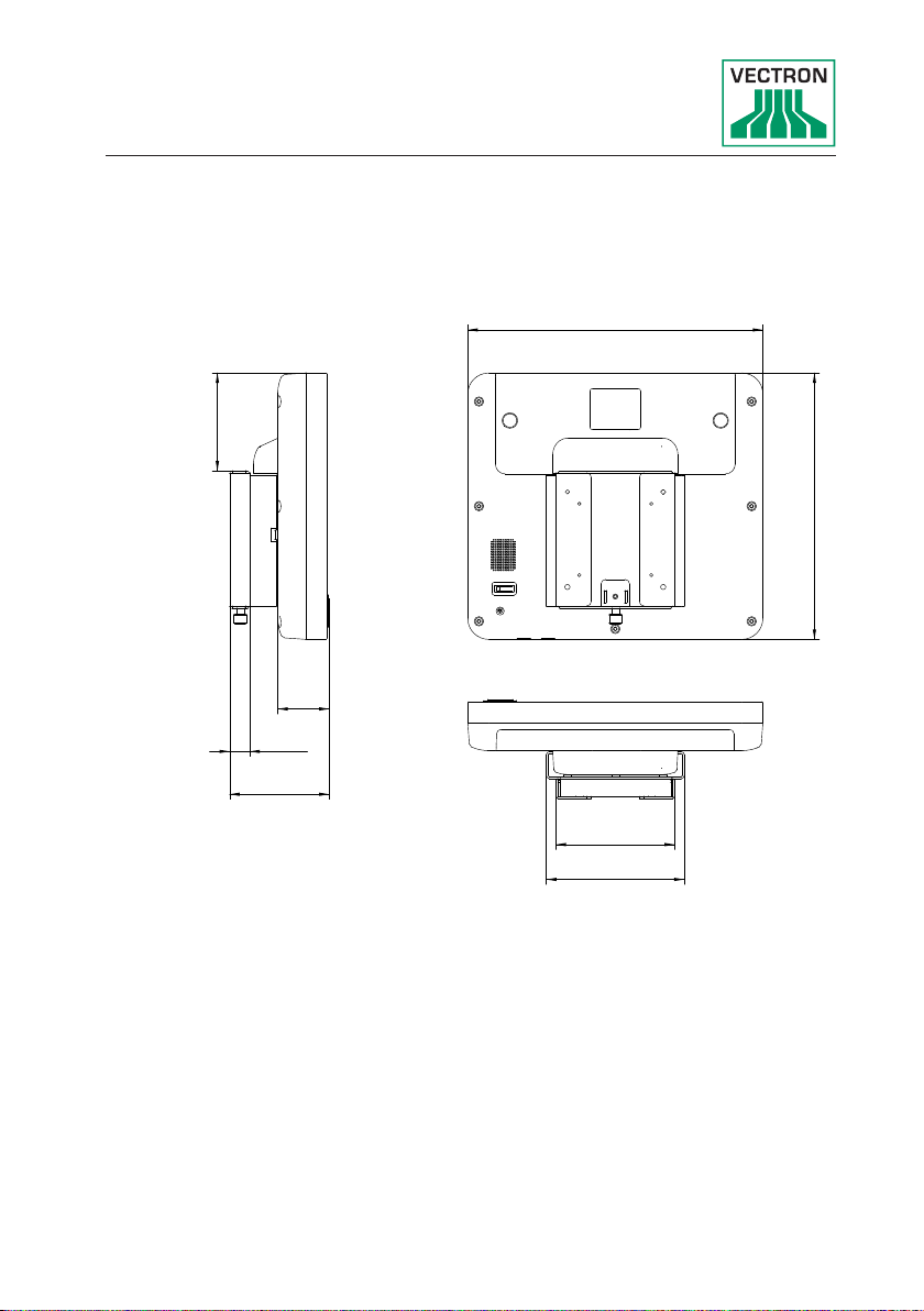
124
(4.9")
144
(5.7")
308
(12.1")
54
(2.1")
21
(0.8")
104
(4.1")
103
(4.1")
280
(11.0")
4.2.6. Dimensions incl. wall mount (in mm and inch)
Fig. 6: POS Touch 12 incl. wall mount (in mm and inch)
21
Page 22
POS TOUCH 12
4
2
1
3
POS TOUCH 12 II PCT
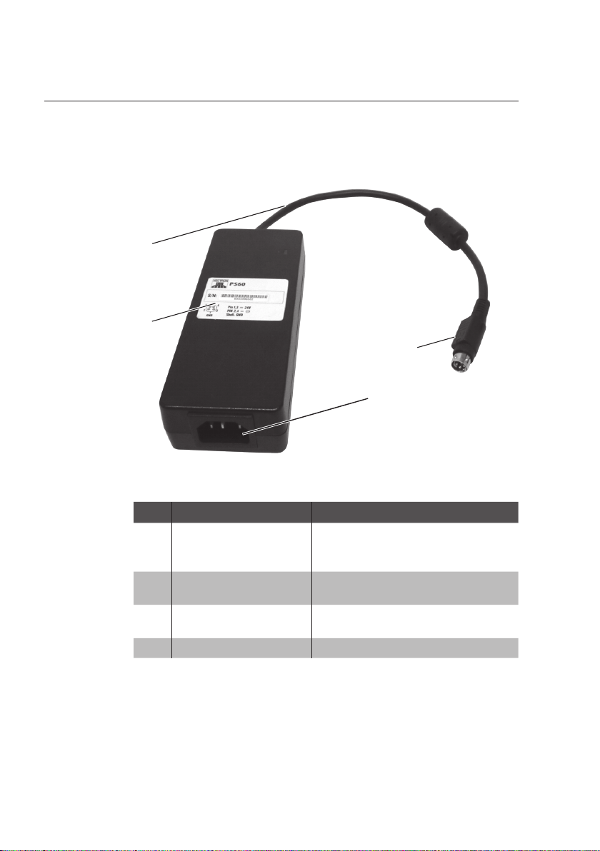
4.3. Power supply PS60
Fig. 7: Power supply PS60
Pos. Designation Description
1 Power supply plug The power supply plug is put
into the power connector of the
POS Touch 12.
2 Panel connector Panel connector for cable cou-
pl e r.
3 Label Product designation and serial
4 Power supply line
number.
22
Page 23
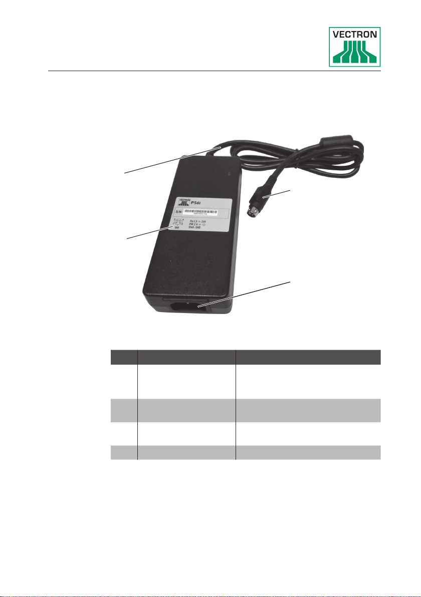
4.4. Power supply PS61
4
3
Fig. 8: Power supply PS61
Pos. Designation Description
1 Power supply plug The power supply plug is put
2 Panel connector Panel connector for cable cou-
3 Label Product designation and serial
4 Power supply line
1
2
into the power connector of the
POS Touch 12.
pl e r.
number.
23
Page 24
POS TOUCH 12
2
1
POS TOUCH 12 II PCT
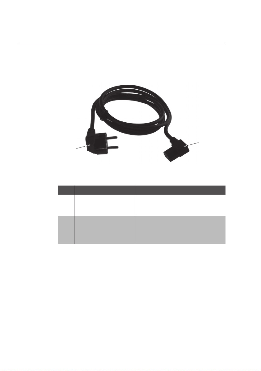
4.5. Mains cable
Pos. Designation Description
1 Cable coupler The cable coupler is plugged
Fig. 9: Mains cable
into the panel connector.
2 Safety plug The safety plug is put into a
so cket.
The safety plug may differ from
the image.
4.6. Vectron POS software
The functions that can be used with the installed Vectron
POS software depend on the software version and the
programming.
Your Vectron specialist retailer will support you should you
have questions on programming or will program the POS
system according to your requirements.
24
Page 25

5. Technical data
5.1. POS Touch 12 POS system
Technical data of the POS Touch 12 POS system
Display diagonal 307 mm (12.1" )
Display type TF T- LCD
Display backlight LED backlight
Display size (active) 246 x 184.5 mm
Display resolution 800 x 600 pixel
Colours Up to VPOS version 5.x: 256 colours
Input Touchscreen; 5-wire analog-resistive
Housing and foot Plastic anthracite and coated metal
Processor Marvell ARMADA 168, 1066 MHz
Main memory 512 MB DDR2-RAM
Cache 1 MB SRAM
Mass memory 4 GB Flash memory
Network 10/100BASE-T; Ethernet
USB ports 8x USB 2.0; type A; 2 of which at the
Serial ports 6x RS232; type RJ45; for additional
Cash drawer ports 2x type RJ12; for up to four cash
Audio socket 3.5 mm jack; stereo; for loudspeaker
SD-card slot For SD-cards up to 4 GB and SDHC-
SIM card slot For standard Mini SIM cards (25 x
Loudspeaker Mono; 2 W
Power supply With foot: Vectron PS60/PS61 (inte-
Buffer battery For permanent power supply of the
As of VPOS version 6.0.0.0: True
Color
bottom
devices
drawers with Y-cable
cards up to 32 GB
15mm)
grated in foot)
With wall mount: Vectron PS61
cache
- as of device revision 1.01
.
25
Page 26

POS TOUCH 12
POS TOUCH 12 II PCT
Technical data of the POS Touch 12 POS system
Power consumption 13 W in normal operation without
Temperature Storage: -10 to 50 °C
Dimensions (W x H
x D)
Weight With foot S400: approx. 9.3 kg
Certified CE
5.2. POS Touch 12 II PCT POS system
Technical data of the POS Touch 12 II PCT POS system
Display diagonal 307 mm (12.1" )
Display type TF T- LCD
Display backlight LED backlight
Display size (active) 246 x 184.5 mm
Display resolution 800 x 600 pixel
Colours True Color
Input Touchscreen (projective-capacitive)
Housing and foot Black plastic and coated metal
Processor i.MX 6, DualLite, 1GHz
Main memory 1 GB DDR3
Mass memory 8 GB Flash memory (eMMC)
Network 10/100/1000 BA SE-T; Ethernet
USB ports 8x USB 2.0; type A; 2 of which at the
Serial ports 6x RS232; type RJ45; for additional
Cash drawer ports 2x type RJ12; for up to four cash
external devices
0.5 W in standby
Operation: 0 to 40 °C
With foot S400: approx. 308 x 390 x
270 mm (depending on tilt angle)
With foot S500: approx. 308 x 200 x
351 mm (depending on tilt angle)
With wall mount: 308 x 280 x 104 mm
With foot S500: approx.5.8 kg
With wall mount: approx. 4.3 kg
bottom
devices
drawers with Y-cable
26
Page 27

Technical data of the POS Touch 12 II PCT POS system
Audio socket 3.5 mm jack; stereo; for loudspeaker
SD-card slot For SD-cards up to 4 GB and SDHC-
cards up to 32 GB
SIM card slot For standard Mini SIM cards (25 x
15mm).
Loudspeaker Mono; 2 W
Power supply With foot: Vectron PS60/PS61 (inte-
grated in foot)
With wall mount: Vectron PS61
Buffer battery For permanent power supply of the
cache
Power consumption 17 W maximum
13 W in normal mode without external
appliances
0.5 W in standby
Temperature Storage: -10 to 50 °C
Operation: 0 to 40 °C
Dimensions (W x H
x D)
Weight With foot S400: approx. 9.3 kg
Certified CE
With foot S400: approx. 308 x 390 x
270 mm (depending on tilt angle)
With foot S500: approx. 308 x 200 x
351 mm (depending on tilt angle)
With wall mount: 308 x 280 x 104 mm
With foot S500: approx.5.8 kg
With wall mount: approx. 4.3 kg
27
Page 28

POS TOUCH 12
POS TOUCH 12 II PCT
5.3. Power supply Vectron PS60 or PS 61
Technical data of power supply Vectron PS60 or Vectron
Input voltage 100 to 240 V alternating voltage
Output voltage + 24 V direct current
Output current Max. 3.75 A
Output power Max. 90 W
Power consumption Max. 93 W
No-load loss 0.3 to 0.5 W
Temperature Storage: -40 to 85 °C
Air humidity Operation: 5 to 95 %, non condensing
Dimensions (W x H
x D)
Weight PS60: 450 g / PS61: 495 g
Certified CE, UL 60950-1
PS61
Operation: 0 to 40 °C
145 x 60 x 32 mm
28
Page 29

5.4. Vectron POS software (POS Touch 12)
Technical data of Vectron POS software
PLUs 1,000,000*
Departments 65,535*
Operators 2,000*
Guest checks or
customers
Cash registers per
network
Printers per network 10 0*
User interface as
of VPOS version
6.0.0.0
bonVito Unrestricted support of the bonVito
* The indicated values are maximum
65,535*
200*
Use of own images and icons also with
transparency channel
Pre-defined high-resolution fonts
online marketing tool (liable to costs more information and prices at www.
bonvito.net)
values, which can only be reached
with special programming and optimum hardware equipment. The available functions also depend on the used
software version and the programming of the POS system. Please contact your Vectron dealer to assist you
with your special requirements.
5.5. Vectron POS software (POS Touch 12 II PCT)
Technical data of Vectron POS software
PLUs 1,000,000*
Departments 65,535*
Operators 2,000*
Guest checks or
customers
65,535*
29
Page 30

POS TOUCH 12
POS TOUCH 12 II PCT
Technical data of Vectron POS software
Cash registers per
network
Printers per network 10 0*
User interface Gesture recognition (swipe) for fast
bonVito Unrestricted support of the bonVito
* The indicated values are maximum
200*
navigation
Use of own images and icons also with
transparency channel
Pre-defined high-resolution fonts
online marketing tool (liable to costs more information and prices at www.
bonvito.net)
values, which can only be reached
with special programming and optimum hardware equipment. The available functions also depend on the used
software version and the programming of the POS system. Please contact your Vectron dealer to assist you
with your special requirements.
30
Page 31

6. Starting
i
6.1. POS Touch 12 set up
6.1.1. Selecting the setup site for POS Touch 12
• Set up the POS Touch 12 in a well ventilated room with a
temperature of between 0 and 40°C.
• The POS Touch 12 must not be covered during operation.
• Select the set-up site so that the POS Touch 12 is not exposed to direct sunlight.
• Place the POS Touch 12 on a stable and even suface with
sufficient space.
• Make sure that no liquids can flow over the POS Touch 12,
the power supply unit or the mains cable.
• Route the cables so that they are not subject to tensile
loading.
• Route the cables so that no one can trip over them.
Your Vectron specialist retailer has programmed
the POS Touch 12 for you. If necessary, he will be
glad to support you during initial start-up and will
train you in using your POS system.
31
Page 32

POS TOUCH 12
POS TOUCH 12 II PCT
6.1.2. Connecting the POS Touch 12 to the power supply
a
a
A CAUTION
Danger of tripping and damaging device
caused by device cables lying unprotected in the room.
X
Route the device cables so that they
do not pose a potential hazard!
X
Route the cables so that they are not
subject to tensile loading.
NOTICE
Damage caused by excessively high
voltages or currents.
X
Use an earthed socket to which
alternating current between 110 and
240 volts is connected.
X
Use power sources which are protected with a residual-current circuit
breake r.
32
• Insert the earthing-pin plug of the mains cable in a socket.
6.1.3. Connecting devices to the POS Touch 12
Your Vectron specialist retailer will be
glad to inform you on available peripher-
i
al devices.
Page 33

6.2. Aligning the screen
Pinching of fingers when aligning the
screen.
The gap between the screen housing and
the joint changes during alignment.
X
q
a
• Adjust the screen to your field of vision by tilting the housing.
Do not insert your fingers between the
screen housing and the joint.
Damage of housing by exceeding the
inclination.
X
Do not incline the screen beyond the
horizontal position.
A CAUTION
NOTICE
Fig. 10: Aligning the screen
33
Page 34

POS TOUCH 12
POS TOUCH 12 II PCT
7. Operation
Buttons that are mentioned in this chapter and
that can be displayed as graphical elements, are
i
7.1 . Switching on and off the POS Touch 12
7.1.1. Switching on the POS Touch 12
If the POS Touch 12 was started as described in chapter 6
“Starting” on page 31 you can switch it on.
• Shortly press the on-/off key to switch on the
POS Touch 12.
shownin chapter 13 “Icons” on page 59.
34
Fig. 11: Switching on and off the POS Touch 12
Page 35

7.1 . 2 . Switching off the POS Touch 12
• Shortly press the on-/off key to switch off the
POS Touch 12.
7.1 . 3. POS Touch 12 reboot
• Shortly press the on-/off key to switch off the
POS Touch 12.
• Wait for approx. 10 seconds.
• Shortly press the on-/off key to switch on the
POS Touch 12.
35
Page 36

POS TOUCH 12
POS TOUCH 12 II PCT
7.2 . User interface
i
After having started and switched on the POS Touch 12 your
POS system is ready for data input.
a
In this chapter we describe an example
configuration of the Vectron POS software.
Programming and configuration of your POS
system may differ considerably from this
example.
Your specialist retailer has programmed
the POS Touch 12 for you and is your
contact partner for questions concerning
the programming.
NOTICE
Damage of touch screen caused by
unsuitable objects.
X
Please touch the screen exclusively
with fingers or the provided stylus.
36
Page 37

7.2 .1. Registration surface
1234
5
6
7
8 109
Fig. 12: Registration surface
Pos. Designation Description
1 Main groups Food or drinks.
2 Departments Subgroups of the respectively se-
lected main group.
3 Scrolling in PLU
selection
4 Button < Media>
5 Button <GC> To open a GC for bookings enter the
GC no. to the numeric pad and press
the <GC> button.
6 Numeric pad Number input
37
Page 38

POS TOUCH 12
POS TOUCH 12 II PCT
Pos. Designation Description
7 Status display 4-column display: signed-in opera-
tor /advertising text (adjustable)/
date/time.
8 Receipt-, invoice-
and GC display
9 Balance display The balance display shows the sum
10 Favourites Favourites stored in programming
Display of various booking data.
of current PLUs on a receipt in field
"Receipt". The balance display also
shows the total of all PLUs booked
to a GC in field "Sales".
for fast selection.
38
Page 39

7.2.2. Payment interface
1234
Fig. 13: Payment interface
Pos. Designation Description
1 Media Media are for example cash- and
credit card payment.
2 Button "GC
move"
3 Button "GC split" Invoicing single PLU or splitting sin-
4 Status display 4-column display: signed-in opera-
Moving all PLUs to another guest
check
gle PLUs to another guest check
tor /advertising text (adjustable)/
date/time.
39
Page 40

POS TOUCH 12
POS TOUCH 12 II PCT
7.3. Sign in/out at POS Touch 12
You can program two types of operator sign in.
If you have an operator key that you want to use for sign in
continue reading in chapter 7.3.2 “Sign in via operator key”
on page 41. If you do not have an operator key continue
reading
in chapter 7.3.1 “Sign in via operator button” on page 40.
7.3.1. Sign in via operator button
a
• Enter the operator number to the numeric pad.Press the
status display on top left.
• Enter the secret code if it is required.
• To sign in the operator press the Enter key for confirmation.
NOTICE
Damage of touch screen caused by
unsuitable objects.
X
Please touch the screen exclusively
with fingers or the provided stylus.
40
•
The operator name appears in the status display.
or
• Press the <Functions> button.
• Press the <Mod. functions 2>.
• Enter the operator number.
Page 41

• To sign in the operator press the <operator> button.
• Enter the secret code if it is required.
• To sign in the operator press the Enter key for confirmation.
The operator name appears in the status display.
Sign out
• To sign out the signed-in operator press on his name in the
status display.
7.3. 2. Sign in via operator key
The operator lock system consists of two elements: operator
lock and operator key.
Every operator key has a unique number.
The number of your operator key is stored
in the operator administration. The Vectron
POS software recognizes by means of this
i
assignment which operator signs in to the
POS system and activates the programmed
operator rights.
• Approach the operator key to the operator lock.
• Enter the secret code if it is required.To sign in the operator
The operator name appears in the status display.
Sign out
• Remove the operator key from the operator lock.
press the Enter key for confirmation.
41
Page 42

POS TOUCH 12
POS TOUCH 12 II PCT
7.4. Working with guest checks (GC)
The GC function serves for invoicing groups or single persons.
7.4.1. Opening a guest check
In order to store GC bookings you first have to open a guest
check.
i
• Enter the GC no.
GCs that already contain bookings but
were not yet invoiced (open GCs), can
be opened again with this function.It
depends on your operator rights whether
you can just open your own GCs or those
of other operators as well.
42
• Press the GC button to open the guest check.
or
• Press the <Open GCs> button.
The list of open GCs is displayed.
• To re-open a GC press on the respective entry in the list.
Page 43

7.4. 2 . Booking PLUs to a GC
• Open the GC that you want to finalize as described in chapter 7.4.1 “Opening a guest check” on page 42.S ele c t the
main group food or the main group drinks.
• Select the department.
• Select the desired PLUs in the PLU selection list.
or
• For multiple booking of a PLU you can enter the desired
number on the keyboard and select the respective PLU.
The display shows the sum of desired PLUs.
7.4. 3 . Closing a GC
If you close a GC to which no PLUs were
booked it will not appear in the list of
i
open GCs.
When you close a GC, bookings for this GC are stored. There
are several ways to close a GC.
• Press the <GC> button.
or
• Open a new GC as described in chapter 7.4.1 “Opening a
guest check” on page 42.
43
Page 44

POS TOUCH 12
POS TOUCH 12 II PCT
7.4.4. Finalizing a GC
Various media are available for finalization. You can select for
example cash- or credit card payment. The GC is closed after
finalization and no longer appears in the list of open GCs.
The bookings are stored in the journal.
The receipt to be printed depends on the programming.
7.4.4.1. Cash payment
Example 1: The customer pays the exact amount:
• Open the GC that you want to finalize as described in
chapter 7.4.1 “Opening a guest check” on page 42.
• Press the <Cash> button.
Example 2: POS system calculates the change:
• Open the GC that you want to finalize as described in
chapter 7.4.1 “Opening a guest check” on page 42.
• Enter the amount you got from the customer on the keyboard.
44
Please note that the amount has to be
entered in cent here. 50 € have to be
entered as 5000.
i
• Press the <Cash> button.
The change amount is displayed.
Page 45

7.4.4.2. Other media
• Open the GC that you want to finalize as described in
chapter 7.4.1 “Opening a guest check” on page 42.
• Press the <Media> button .
The payment interface appears
• Press the button of the desired media.
7.4. 5 . Separate invoicing of groups or single persons
The GC split function can only be carried
out if all PLUs of the GC have been
booked. Close the open GC as described
i
• Open the GC that you want to split as described in chapter
7.4.1 “Opening a guest check” on page 42.
• Press the <Media> button .
in chapter 7.4.3 “Closing a GC” on page
43.
• Press the <GC split> button .
• Select the PLUs to be split in the right column.
The PLU will be moved to the left.
• After having selected all the PLUs press the button for the
desired media to invoice the split PLUs.
• To open the registration interface press the <previous>
button.
45
Page 46

POS TOUCH 12
POS TOUCH 12 II PCT
7.4.6 . Splitting single PLUs to another guest check
i
• Open the GC that you want to split as described in chapter
7.4.1 “Opening a guest check” on page 42.
• Press the <Media> button .
• Enter the number of the GC to which the PLUs are to be
moved.
• Press the <GC split> button .
In the left column you see the number of the GC to which the
PLUs are to be moved.
• Select the PLUs to be split in the right column.
The GC split function can only be carried
out if all PLUs of the GC have been
booked. Close the open GC as described
in chapter 7.4.3 “Closing a GC” on page
43.
46
The PLU will be moved to the left.
• After having selected all the PLUs press the <previous>
button .
The selected PLUs will be transferred.
Page 47

7.4.7. Moving all PLUs to another guest check
The GC move function serves for transferring all PLUs of one
guest check to another.
The GC split function can only be carried
out if all PLUs of the GC have been
booked. Close the open GC as described
i
• Open the GC that you want to move as described in chapter
7.4.1 “Opening a guest check” on page 42.
• Press the <Media> button .
• Enter the number of the GC to which the PLUs are to be
moved.
• Press the <GC move> button .
All PLUs of the open GC are moved to the selected GC.
7.4.8. Transferring a GC to another operator
in chapter 7.4.3 “Closing a GC” on page
43.
This function serves for transferring a guest check to another
operator.
This function can be enabled optionally.
47
Page 48

POS TOUCH 12
POS TOUCH 12 II PCT
7.5. Working with hold buffers
The hold buffer function allows several operators to work
simultaneously at one POS system. The first operator opens a
hold buffer, signs in and books the PLUs.
If a second operator wants to use the POS system in the
meantime, he presses a new hold buffer button, signs in and
books the PLUs. The operators' bookings are stored in the
respective hold buffer until media finalization.
This function can be enabled optionally.
7.6. Working with reports
Reports serve for evaluating data that were stored in the POS
system.
With POS software you can create two types of reports: X-reports and Z-reports.
48
Z-reports are final reports where the data is deleted from the
booking memory. X-reports are intermediate reports, where
the data is just polled.
This function can be enabled optionally.
7.7. Correction or void last entry
This function can be enabled optionally.
Page 49

7.8. Print data server
Each POS system in network can be programmed to work as
print data server in addition to the POS system function.
A print data server serves for receiving print data from
another POS system in network, for processing them and
printing them on a locally connected printer.You can install
several print data servers.
Orders that you enter to your POS Touch 12 can be printed
automatically in the kitchen for example. After the payment
the POS system can print the invoice automatically at the
counter for example.
49
Page 50

POS TOUCH 12
POS TOUCH 12 II PCT
8. Service and maintenance
8.1. Cleaning
A DANGER
Deadly shock caused by penetrating
liquids.
X
Do not open the Vectron
POS Touch 12 or the power supply.
X
s
a
Prior to cleaning the POS Touch 12
switch it off as described in chapter
10 “Shutdown” on page 55.
NOTICE
Aggressive cleansers can damage the
housing surface.
X
Do not use any scouring or dissolving
agents for cleaning.
X
If necessary clean the housing surface
with a smooth, lint-free cloth. In case
of strong contamination you can
dampen the cloth with water or with a
mild, residue-free cleanser.
50
Page 51

8.2. Contacting the customer service
Your Vectron dealer will answer your questions concerning
the POS Touch 12 and peripherals and will support you with
configuration and operation.
A DANGER
Deadly shock caused by improper repairs.
Some components can contain high
residual voltages which discharge when
touched.
X
s
Contact your Vectron specialist
retailer if POS system components are
damaged.
51
Page 52

POS TOUCH 12
POS TOUCH 12 II PCT
9. Errors, possible reasons and troubleshooting
Errors Possible reasons Troubleshooting
The POS Touch 12
cannot be switched
on.
The POS Touch 12
does not react to
your entries.
The safety plug is
not plugged to a
voltage-carrying
outlet.
The power supply
plug is not put
into the power
connector of the
POS Touch 12.
The On/Off key is
damaged.
The power supply is
damaged.
The POS Touch 12
is damaged.
The signed-in operator is not authorized for the respective function.
The touchscreen is
not calibrated.
The Ve ctron P OS
software has a malfunction.
Insert the safety plug
of the supplied power cord to an earthed
socket to which alternating current between
110 and 240 volts is
connected and which
is protected with a
residual-current circuit
breaker.
Put the power supply
plug into the power connector of the
POS Touch 12.
Contact your Vectron
dealer.
Contact your Vectron
dealer.
Contact your Vectron
dealer.
Contact your Vectron
dealer.
Contact your Vectron
dealer.
Reboo t the
POS Touch 12 as described in chapter 7.1.3
“POS Touch 12 rebo ot”
on page 35.
52
Page 53

Errors Possible reasons Troubleshooting
The POS Touch 12
does not display
anything.
The POS Touch 12
processes other
entries than those
made on the touch
screen.
Faulty programming
and configuration of
POS Touch 12.
The touch screen is
damaged.
The POS Touch 12
is switched off.
The screen saver is
active.
The Ve ctron P OS
software has a malfunction.
The power supply is
damaged.
The POS Touch 12
is damaged.
The touchscreen is
not calibrated.
The Ve ctron P OS
software has a malfunction.
Faulty programming
and configuration of
POS Touch 12.
The touch screen is
damaged.
Contact your Vectron
dealer.
Contact your Vectron
dealer.
Press the On/Off key
as described in chapter
7.1.1 “Switching on the
POS Touch 12” on page
34.
Touch the screen with
the stylus or with a
finger.
Contact your Vectron
dealer.
Contact your Vectron
dealer.
Contact your Vectron
dealer.
Contact your Vectron
dealer.
Reboo t the
POS Touch 12 as described in chapter 7.1.3
“POS Touch 12 rebo ot”
on page 35.
Contact your Vectron
dealer.
Contact your Vectron
dealer.
53
Page 54

POS TOUCH 12
POS TOUCH 12 II PCT
Errors Possible reasons Troubleshooting
The sound reproduction of the
POS Touch 12 do es
not work.
You cannot
sign in to the
POS Touch 12 with
operator key via the
operator lock.
Loudspeakers are
connected to the
audio port but the
volume is too low.
The sound reproduction was neither
programmed nor
configured.
The loudspeakers
are damaged.
The audio port is
damaged.
The operator lock
was neither programmed nor configured.
Operator lock or
operator key are
damaged.
Adjust the volume.
Contact your Vectron
dealer.
Exchange the loudspeakers.
Contact your Vectron
dealer.
Contact your Vectron
dealer.
Contact your Vectron
dealer.
54
Page 55

10. Shutdown
Shut down the POS Touch 12 if you do not use it for a longer time.
• Shortly press the on-/off key to switch off the POS Touch 12.
Fig. 14: Switching off the POS Touch 12
• Unplug the safety plug of the power supply from the socket.
• Remove all cables connected to the POS Touch 12.
• Store the POS Touch 12 in a room with a temperature of between
-10 and 50 °C.
55
Page 56

POS TOUCH 12
POS TOUCH 12 II PCT
11. Disposal
Directive 2012/19/EU (WEEE)
Waste electric and electronic equipment must not be
disposed of together with domestic waste.
Vectron Systems AG takes back waste electric and
electronic equipment that has been used for commercial purposes and that was produced by or on behalf
of the company. The company disposes of the waste
electric and electronic equipment properly.
The legal take-back obligation applies for devices that were put on
the market after 13 August 2005. In addition, Vectron Systems AG
extends this obligation to all devices that have been put on the market as of 1 January 2004.
Please send back waste electric and electronic equipment that was
produced by or on behalf of as well as their accessories in the original packaging, marked "Waste electric and electronic equipment"
franco domicile to Vectron Systems AG.
WEEE-Reg.-Nr. DE 91733199
56
Page 57

12. Glossary
This chapter explains the terms that are used in context with the
POS Touch 12.
Term Definition
User interface All display elements and buttons on the
Booking memory Memory that stores every booking of the
Button A button is programmed in the POS system
Media finalization Method for finalizing an invoice. Media are
Flash memory Memory in which data is kept even after the
Icon Pictograph used in graphical user interfaces.
LCD Liquid Crystal Display
POS Point Of Sale In this context the POS system
Registration surface Surface that is displayed on the screen. On
Thin Film Transistor Electronic component for control of screens.
GC server POS system, which in the ECR network takes
Touchscreen Input device that releases POS system func-
X-repo rt Intermediate report, where data is kept in
screen that are meant to show information or
execute functions.
operators.
and releases commands.
for example cash- and credit card payment.
voltage supply was switched off.
When touching or clicking on icons you call
functions of the Vec tron POS software.
station.
the registrier surface you can book PLUs to
guest checks.
over the central guest check management.
tions when an operator touches the buttons
on the screen.
the booking memory of the POS system.
57
Page 58

POS TOUCH 12
POS TOUCH 12 II PCT
Term Definition
Payment interface Surface that is displayed on the screen.
Z-r epor t Final report where the data is deleted from
Here you can make payments using different
media.
the booking memory.
58
Page 59

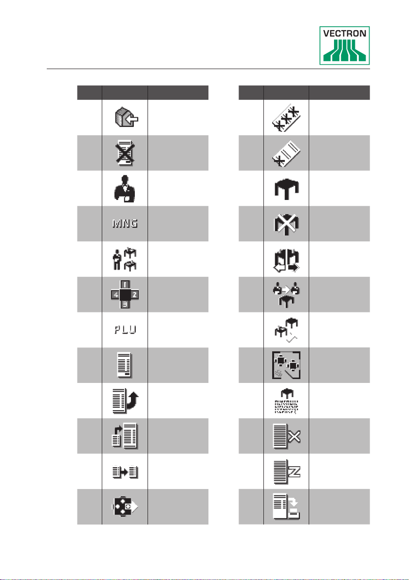
13. Icons
Icons are graphics that symbolize defined functions. Icons mark defined spaces on the screen, which are called buttons.
By touching the buttons on the screen of you call functions or select
PLUs.
This chapter lists the icons integrated in POS software and explains
their meaning. Furthermore, you can load additional icons.
No. Icon Meaning
1 Vectron POS
2 Centred
3 Left-aligned
4
5 Enter
6 Field up
7 Field down
Rightaligned
No. Icon Meaning
8 Cursor left
9 Cursor right
10 Page up
11 Page down
12 Field left
13 Field right
14 Shift
59
Page 60

POS TOUCH 12
POS TOUCH 12 II PCT
No. Icon Meaning
15 Shift Lock
16 Editor
17 New record
18
19 Print
20 Next record
21
22 Goto record
Delete records
Previous
record
No. Icon Meaning
27 Text search
28 Send
29 Load
30 Save
31 Network
32 Clear
33 Escape
34 Mode
60
23 Select
24 Mark
25 Mark
26 Table / Mask
101 Take away
102
103 Receipt copy
104 Guest count
Ca nce l
receipt
Page 61
No. Icon Meaning
No. Icon Meaning
105 Inhouse
106 No invoice
107 Operator
Manager
108
109
110 Seat number
111 PLU
112 Invoice
113 Load invoice
functions
only
Open operator GCs
117 Void
118
119 GC
120 GC 0
121 GC split
122 Transfer GC
123 GC move
124 Table map
125
Void last
entry
Ente r GC
text
114
115 Invoice copy
116 Seat split
Recall
invoice
126 X- rep orts
127 Z- rep orts
128 Subtotal GC
61
Page 62

POS TOUCH 12
POS TOUCH 12 II PCT
No. Icon Meaning
129 Subtotal
130 Deposit
131 Paid out
132
133 Receipt on
134 Receipt off
135 Data input
136
Operator
report
Print format
shift
No. Icon Meaning
141
142
143
201 Cash
202 Media
401 Cold drinks
402 Hot drinks
403 Side dishes
Table reservation
Department
DPT
Department
WG
62
137
138 VIP sale
139 Journal
140 Price
Received
amount
404 Beer
405 Icecream
406 Fish
407 Meat
Page 63

No. Icon Meaning
408 Drinks
409
410 Desserts
411 Pizza
412 Spirits
413 Starters
414 Wine
415 Vegetables
416 Salad
Main courses
63
Page 64

POS TOUCH 12
POS TOUCH 12 II PCT
14. EU Declaration of Conformity
Manufacturer Vectron Systems AG
Willy-Brandt-Weg 41
D-48155 Münster
Device type Stationary POS system
Type designation
The manufacturer declares that the above designated product consistent with directive 2001/95/EC complies with the fundamental
standards on electrical and electronic products as stipulated in the
directives of the European Council. The below mentioned standards
that were harmonised under the relevant directives were applied:
Directive Standards
2014/ 30/EC
Directive on
electromagnetic
compatibility
2014/35/EC
Low Voltage Directive
2011/65/EU
Restriction of the use
of certain hazardous
substances (RoHS)
Vectron POS Touch 12,
POS Touch 12 II PCT
EN 55022 Kl. B:2010; EN 55024:2010,
EN 61000-3-2:2014; EN 61000-3-3:2013
EN 60950-1:2006+A11:2009+A12:2011+
A1:2010 +A2: 2013
EN 50581:2012
64
This declaration is made in authority for the manufacturer resident in
the European Union.
Mün s ter, 2016 -12-15
Jens Reckendorf
Member of the Board
Thomas Stümmler
Member of the Board
Page 65

15. Accessories
At this point we would like to inform you about the accessories you
can purchase for the POS Touch 12. For more information and the
technical data for accessories please see the website at www.vectronsystems.com.
For questions concerning our products please contact your Vectron
dealer.
15.1. Operator lock systems
The operator lock system serves for sign in to the
POS Touch 12.
Various operator lock systems can be mounted to the
POS Touch 12.
15.1.1. Operator lock L10 T15/T12
Fig. 15: Operator lock L10 T15/T12
65
Page 66

POS TOUCH 12
POS TOUCH 12 II PCT
15.1.2. Operator lock L21 T15/T12
Fig. 16: Operator lock L21 T15/T12
15.1.3. Operator lock L30 T15/T12
66
Fig. 17: Operator lock L30 T15/T12
Page 67

15.1.4. Operator lock Vectron L10
Fig. 18: Operator lock Vectron L10
15.1.5. Operator lock Vectron L21
Fig. 19: Operator lock Vectron L21
15.1.6. Operator lock Vectron L30
Fig. 20: Operator lock Vectron L30
67
Page 68

POS TOUCH 12
POS TOUCH 12 II PCT
15.2. Customer displays
On Vectron customer displays you can show texts and
graphics, e.g. to inform your customers about special offers.
15.2.1. Customer display Vectron C56
The customer display Vectron C56 is mounted to the screen
housing of the POS system or to a stand.
The Ve ctron C56 has a screen diagonal of 13.16 cm (5.2“), for
display of 2 x 20 characters.
On the customer display you can show texts and graphics.
The Ve ctron C56 has a resolution of 240 x 64 pixels.
68
Fig. 21: Customer display Vectron C56
Page 69

15.2.2. Customer display Vectron C75
The customer display Vectron C75 is mounted to the screen
housing of the POS system or to a stand.
The customer display Vectron C75 has a screen diagonal of
17.78 cm (7“).
On the customer display you can show texts and graphics.
The Ve ctron C75 has a resolution of 800 x 480 pixels.
Fig. 22: Customer display Vectron C75
69
Page 70

POS TOUCH 12
POS TOUCH 12 II PCT
15.2.3. Customer display Vectron C10 0
The 10.4“ customer display Vectron C100 is suitable for
display of sales information, logos and advertising images.
The images can also be shown as slide show. Furthermore,
event-related campaigns/texts can be released on the display.
The Vectron C100 can be connected directly to the stationary
POS systems Vectron POS Mini II, Vectron POS Vario II,
Vectron POS Touch 12 and Vectron POS Touch15.
The customer display is alternatively available as pole variant, which is also compatible to Vectron POS SteelTouch II.
For optimum alignment to the client‘s position, the tilt angle
of the high-resolution graphical display with LED backlight is
fully adjustable.
70
Fig. 23: Customer display Vectron C100
Page 71

15.3. Extension cable Vectron PS60
Extends the cable of the power supply Vectron PS60.
Fig. 24: Extension cable Vectron PS60
15.4. Stylus
The stylus serves for entering data via the touchscreen of
POS Touch 12.
15.4.1. Vectron stylus
The Ve ctron stylus serves for entering data via the touchscreen of POS Touch 12. The Vectron stylus is made from
plastic.
The Vectron touch pen cannot be used at
the Vectron POS Touch 12 II PCT!
i
Fig. 25: Vectron stylus
71
Page 72

POS TOUCH 12
POS TOUCH 12 II PCT
15.4.2. Multifunction stylus
The multifunction stylus serves for entering data via the
touchscreen of POS Touch 12.
The multifunction stylus has an integrated ball pen refill. You
can switch between write- and touch function by turning the
casing.
i
The Vectron touch pen cannot be used at
the Vectron POS Touch 12 II PCT!
Fig. 26: Multifunction stylus
72
15.4.3. Touchpen Vectron PCT
The stylus serves for entering data via the touch screen of the
POS Touch 12 II PCT.
Abb. 1: Stylus Vectron PCT
Page 73

16. Other Vectron products
Here we would like to inform you about additional Vectron products.
For more information and the technical data for Vectron products
please see the website at www.vectron-systems.com.
For questions concerning our products please contact your Vectron
dealer.
16.1. Stationary Vectron POS systems
Stationary Vectron POS systems with fast and reliable hardware are perfectly suited to single station use.
Their special server attribute also allows data exchange with
other stationary and mobile Vectron POS systems.
The large product range provides the ideal Vectron POS
system for any application.
73
Page 74

POS TOUCH 12
POS TOUCH 12 II PCT
16.1.1. Vectron POS Touch 15, POS Touch 15 PCT,
POS Touch 15 II PCT
Vectron POS Touch 15 has a 38.1 cm display (15“).
Data is entered via touch screen.
74
Fig. 27: Vectron POS Touch 15
Page 75

16.1.2. Vectron POS Vario II
Vectron POS Vario II has a 307 mm display (12,1“ ).
Data is entered either via the flat keyboard or via touch
screen.
Fig. 28: Vectron POS Vario II
75
Page 76

POS TOUCH 12
POS TOUCH 12 II PCT
16.1.3. Vectron POS Mini II
Vectron POS Mini II POS Mini II has a 178 mm display (7“).
Data is entered either via the flat keyboard or via touch
screen (when using the software light licence, data input is
made exclusively via keyboard).
76
Fig. 29: Vectron POS Mini II
Page 77

16.2. Mobile Vectron POS systems
16.2.1. Vectron POS MobilePro III
The Vectron POS MobilePro is a robust and completely watertight mobile POS system that is suitable for indoor- and outdoor
use. The high-quality TFT-LCD with glass surface and background
lighting and provides good legibility in daylight and artificial light.
Thanks to the practical combination of capacitive touch and
keyboard it is fast to operate and is therefore particularly
recommended for companies with high customer frequency or
at peak times. The POS system is lightweight and ergonomically
shaped to make the work more convenient.
Fig. 30: Vectron POS MobilePro III
77
Page 78

POS TOUCH 12
POS TOUCH 12 II PCT
16.3. Software
16.3.1. Vectron Mobile App
The new ECR app for hospitality professionals is so easy to
operate that you will be familiar with all the functions within
minutes. At the same time the app provides you all the comfort you require for mobile cashing.
78
Abb. 2: Vectron Mobile App
Page 79

16.3.2. Vectron Commander
The Commander is the communication- and evaluation software for Vec tron POS systems. You can use the software on
computers with operating system Microsoft® Windows®.
With the Vectron Commander you can retrieve, evaluate and
manage the data of the Vectron POS systems. The software
helps you get an overview on sales, order, and the working
times of your staff.
Data can be sent to and received from several POS systems
simultaneously.
Vectron Commander has an integrated user rights administration that allows you assigning individual rights for every user.
The POS Anywhere function enables you to connect via network or modem to POS sytems and control them remotely and
to monitor operating procedures.
The Commander can be used as interface between external
like e.g. ERP systems and POS systems.
79
Page 80

POS TOUCH 12
POS TOUCH 12 II PCT
16.3.3. Vectron Journal Tool
Vectron Journal Tool is a tool for evaluation, archiving and
analysis for the POS system‘s journal data that was read by
means of the Vectron Commander.
Companies of all trades profit from the comprehensive functions. All sales and transactions are displayed in detail. The
respective transactions for each receipt (e.g. subtotal, split
receipt, invoice) are displayed.
The software can be installed on common PCs by using a
Microsoft SQL database.
16.3.4. Vectron POS PC
POS PC is software that you can use on computers with
operating system Microsoft® Windows®.
You can use the software in addition to the usual Windows
applications like e-mail-, office- and ERP applications.
80
The POS PC software is compatible to all mobile and
stationary POS systems, Vectron Commander and Vectron
Journal Tool.
16.4. bonVito
bonVito is Vectron‘s solution for customer loyalty.
All customer retention promotions are conveniently processed
automatically via the Vectron POS system during the
payment process. bonVito provides individual customer cards,
collection and redemption of points, digital stamps, payment
function and coupons per e-mail, text message or reciept
imprint.
 Loading...