

Page 1

VECTRON SYSTEMS
Vectron POS Vario II
User manual
Page 2

Page 3

Your Vectron dealer
Stamp
Date: 19.10. 2012
© 2011 to 2012 by Vectron Systems AG
Subject to error and technical modification
Manufacturer
Vectron Systems AG
Willy-Brandt-Weg 41
48155 Muenster, Germany
www.vectron.de
Leading in POS Technology
Vectron
3
Page 4

Page 5

Contents
1. Terms, signs and symbols .................................................11
1.1. Notes on safety............................................................................... 11
1.1.1. Signal words .................................................................................... 12
1.1.2. Safety symbols ............................................................................... 13
1.2. References to information ............................................................ 13
2. General notes on safety .................................................... 14
3. About this manual .............................................................. 16
3.1. Target group ................................................................................... 16
3.2. Purpose............................................................................................ 16
3.3. Dealer support ................................................................................ 16
3.4. Explanatory notes on content ...................................................... 17
4. Specification ......................................................................19
4.1. Vario II POS system ........................................................................ 19
4.2. Vectron POS software ................................................................... 21
4.3. Use as directed ............................................................................... 22
4.4. Technical data ................................................................................. 25
4.4.1. Vario II POS system ........................................................................25
4.4.2. Power supply Vectron PS30 ......................................................... 27
4.4.3. Vectron POS software ................................................................... 28
5. Device description .............................................................29
5.1. Shipment .........................................................................................29
5.2. Device description ..........................................................................29
5.2.1. Vario II front view........................................................................... 30
5.2.2. Vario II rear view ............................................................................ 32
5.2.3. Vario II bottom view ....................................................................... 34
5.2.4. Ports and connections detailed view........................................... 36
5.2.5. Power supply Vectron PS30 ......................................................... 38
5.2.6. Power cord ...................................................................................... 40
5.3. Dimensions ...................................................................................... 42
5
Page 6

VECTRON POS VARIO II
6. Starting ............................................................................... 43
6.1. Set up of Vario II ............................................................................ 44
6.1.1. Selecting the setup site for Vario II .............................................44
6.1.2. Connecting Vario II to the power supply ..................................... 45
6.1.3. Connecting devices to Vario II ...................................................... 47
6.2. Placing the insert ...........................................................................48
6.3. Adjusting the display ..................................................................... 49
6.4. Adjusting the customer display .................................................... 50
7. Operation ............................................................................ 51
7.1. Switching the Vario II on and off .................................................. 51
7.1.1. Switching on the Vario II ............................................................... 51
7.1.2. Switching off the Vario II...............................................................52
7.2. Entering data to the Vario II ......................................................... 53
7.2.1. Entering data via the flat keyboard .............................................54
7.2.2. Entering data via touch screen .................................................... 54
7.3. Sign in to Vario II ............................................................................ 57
7.3.1. Sign in via operator button ........................................................... 58
7.3.2. Sign in via operator key ................................................................ 59
7.4. Sign out from the Vario II ..............................................................62
7.4.1. Sign out via operator button ........................................................62
7.4.2. Sign out via operator key .............................................................. 63
7.5. Working with guest checks ...........................................................64
7.5.1. Opening a GC ..................................................................................64
7.5.2. Booking PLUs to a guest check ....................................................65
7.5.3. Closing a GC .................................................................................... 65
7.5.4. Finalizing a GC ................................................................................ 66
7.5.5. Splitting PLUs of a guest check to invoice ................................. 67
7.5.6. Splitting single PLUs of a guest check to another guest
check ................................................................................................ 68
7.5.7. Moving all PLUs of one guest check to another guest check ... 69
7.5.8. Transferring a guest check to another operator ....................... 69
7.6. Working with hold buffers ............................................................. 70
7.7. Working with reports ..................................................................... 71
7.8. Void and Correction ....................................................................... 72
7.9. Restarting Vario II .......................................................................... 72
6
Page 7

8. Shut down ........................................................................... 73
9. Errors, possible reasons and troubleshooting ................ 76
10. Service and maintenance ..................................................79
10.1. Cleaning ........................................................................................... 79
10.1.1. Cleaning housing and display ....................................................... 79
10.1.2. Cleaning the contacts .................................................................... 79
10.2. Maintenance ....................................................................................79
10.2.1. Exchanging the insert .................................................................... 80
10.3. Contacting the customer service ................................................. 81
11. Disposal ..............................................................................82
12. Glossary ..............................................................................83
13. Icons ....................................................................................85
14. EC Declaration of conformity ............................................94
15. Accessories ........................................................................95
15.1. Operator lock systems ................................................................... 95
15.1.1. Operator lock Vectron L10 ...........................................................95
15.1.2. Operator lock Vectron L20 ........................................................... 96
15.1.3. Operator lock Vectron L30 ........................................................... 96
15.2. Customer displays ..........................................................................97
15.2.1. Customer display Vectron C56 .....................................................97
15.2.2. Customer display Vectron C75 .....................................................98
15.3. Touch pens ...................................................................................... 99
15.3.1. Vectron Touch pen .........................................................................99
15.3.2. Multifunction touch pen ................................................................ 99
7
Page 8

VECTRON POS VARIO II
16. Other Vectron products ..................................................100
16.1. Stationary POS systems ..............................................................100
16.1.1. Vectron POS ColorTouch .............................................................101
16.1.2. Vectron POS Mini II ...................................................................... 102
16.1.3. Vectron POS Modular ..................................................................103
16.1.4. Vectron POS SteelTouch II ..........................................................104
16.1.5. Vectron POS SteelTouch Light ...................................................105
16.1.6. Vectron POS SteelTouch PC ........................................................10 6
16.2. Hybrid and mobile POS systems.................................................107
16.2.1. Vectron POS MobilePad ...............................................................107
16.2.2. Vectron POS MobilePro ............................................................... 108
16.2.3. Vectron POS MobileTouch ...........................................................109
16.2.4. Vectron POS MobileXL ................................................................. 110
16.3. Software ........................................................................................ 111
16.3.1. Vectron Commander ....................................................................111
16.3.2. Vectron POS software .................................................................112
16.3.3. Vectron POS PC ............................................................................112
16.4. bonVito ..........................................................................................112
8
Page 9

Page 10

Page 11
1. Terms, signs and symbols
This chapter informs you about the terms, signs and symbols that
are used in this manual.
1.1. Notes on safety
This user manual contains safety notes, which indicate
hazards when operating the Vectron POS Vario II, in the
following referred to as Vario II.
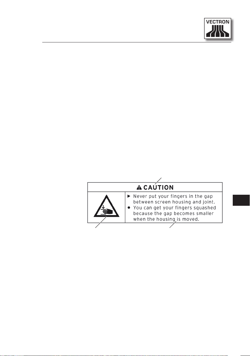
Each safety note consists of three elements, the signal
word (1), the word message (2) and the safety symbol (3).
1
EN
3
Fig. 1: Example for a safety note
The instructions following the safety note tell you how to
behave in order to avoid the hazard.
2
11
Page 12
VECTRON POS VARIO II
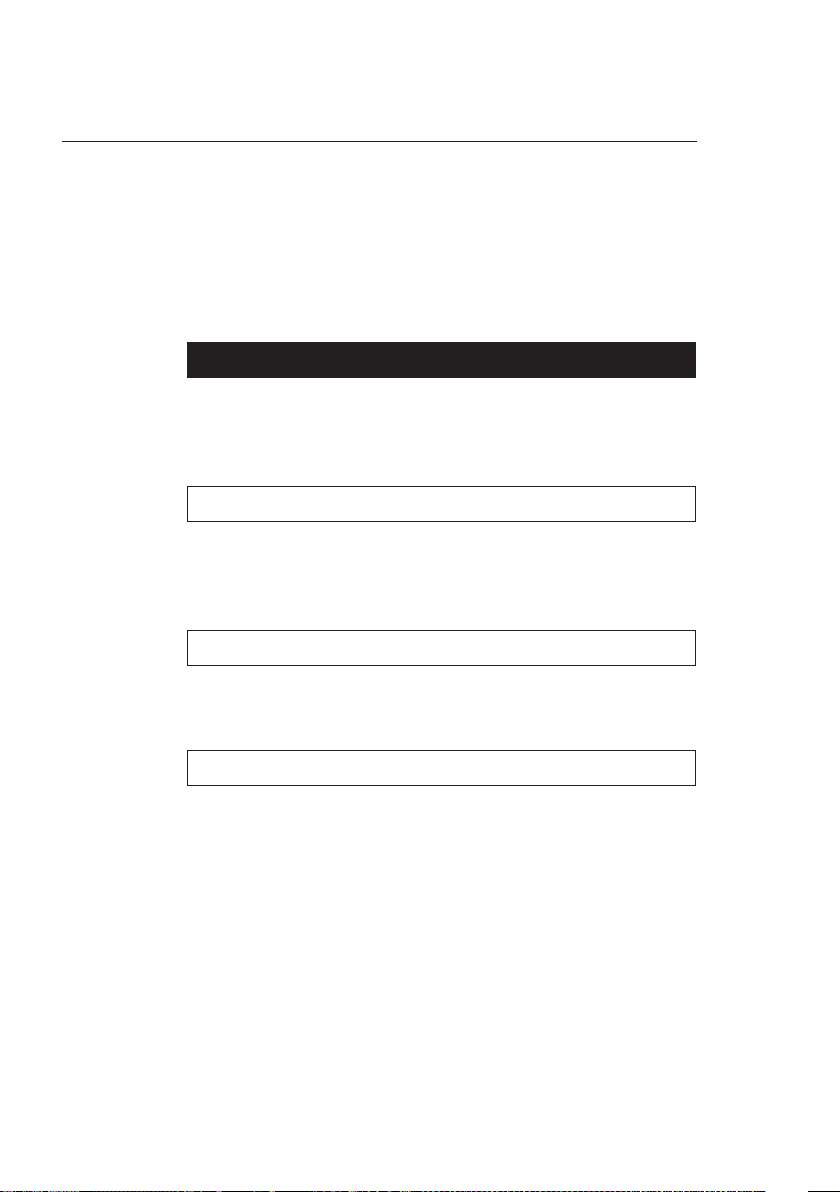
1.1.1. Signal words
Signal words inform you about the risk of danger. The risk
contains information on how serious injuries are and how
probable it is that an injury will occur.
The signal word “DANGER” indicates a danger with high
risk, which will result in death or severe injury if it is not
avoided.
The signal word “WARNING” indicates a danger with medium risk, which could result in death or severe injury if it
is not avoided.
The signal word “CAUTION” indicates a danger with low
risk, which could result in minor injuries if it is not avoided.
A DANGER
A WARNING
A CAUTION
12
NOTICE
The signal word “NOTICE” indicates a danger, which could
result in material damage if it is not avoided.
Page 13
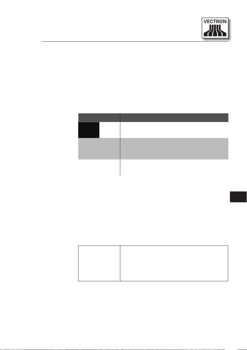
1.1.2. Safety symbols
Each safety note contains a safety symbol, which marks
the hazard graphically. If no special safety symbol is available, the general safety symbol is used.
Safety symbols have the following meaning:
Symbol Meaning
General safety symbols for signal word
A A
a
q
panels, warning of personal injuries.
General safety symbol for hazards for
which no special safety symbol is available.
Special safety symbol for hazards
through crushing.
1.2. References to information
This user manual contains information that refer to helpful
information concerning the handling of Vario II.
The information signal has the following meaning:
The information signal indicates references to information that can be helpful
when operating the Vario II.
i
EN
13
Page 14

VECTRON POS VARIO II
2. General notes on safety
This chapter informs you about general hazards that exist when
operating the Vario II.
Observe the following notes on safety by all means:
A DANGER
• Use exclusively undamaged power cords, power supplies and
POS systems in their original state. You can suffer an electric
shock, if for instance the components of the POS system are
not insulated properly. Please contact your Vectron dealer if
the components of the POS system are damaged.
• Never open the power supply and the POS system, e.g. in order
to repair the components of the POS system yourself. Yo u ca n
suffer an electric shock, since some components can have
residual current, which discharges when being touched. Please
contact your Vectron dealer if the components of the POS system are damaged.
A CAUTION
• Never put your fingers into the small gap between display
housing and hinge. You can crush your fingers, since the gap
becomes smaller when the display housing is moved. Before
adjusting the display please read chapter 6.3 “Adjusting the
display” on page 49.
14
Page 15

NOTICE
• Never set up the power supply and the POS system other than
described in the instructions. You can damage the compo-
nents of the POS system, if for instance the setup site is not
stable. Prior to setup please read chapter 6.1.1 “Selecting the
setup site for Vario II” on page 44.
• Put the safety plug of the supplied power cord exclusively into
a grounded socket with alternating voltage between 110 and
240 volt, which is protected with a fault current circuit breaker.
You can damage the power supply and the POS system, if for
instance voltage and current of another power supply network
are too high for the electronics.
• Have the programming, configuration and program functions
protected by passwords. Operators can change the program-
ming and configuration and execute program functions
deliberately or unintentionally, so that data is changed or
deleted and e.g. is no longer within the law. Please contact your
Vectron dealer, who will assign the operator rights according to
your requests.
• Never change the programming and configuration if you lack
sufficient knowledge and abilities. You can change them un-
intentionally, so that data is changed or deleted and e.g. is no
longer within the law. Please contact your Vectron dealer, who
will program and configure the POS system according to your
requests.
• Never use caustic cleansers for cleaning power supply and
POS system. You can damage the surface of the POS system
components, since caustic cleansers cause a chemical reaction
with the surface materials. Prior to cleaning read chapter 10.1
“Cleaning” on page 79.
• Always send the power supply and the POS system in the original packaging. The POS system components can be damaged
during transport, as another packaging may not absorb the
shocks as required. Keep the original packaging.
EN
15
Page 16

VECTRON POS VARIO II
3. About this manual
This user manual is part of the Vario II. The user manual must be
kept together with Vario II. When forwarding the Vario II please
forward this manual as well.
3.1. Target group
This user manual is meant for end users of the Vario II.
3.2. Purpose
This user manual informs you about performance and features of the Vario II. It is meant to inform you about how to
start, operate and close down the Vario II.
3.3. Dealer support
16
Vectron Systems AG is the manufacturer of Vario II.
Vectron does not sell the Vario II directly to end users. The
Vectron specialist dealer from whom you purchased the
Vario II is your contact partner for all questions concerning the POS system.
The Vario II POS systems which Vectron sells to their
specialist dealers are neither programmed nor configured.
Your Vectron dealer should have programmed and configured your Vario II POS system after consulting you and
according to your requests.
Page 17

For this reason, this user manual contains only the information that applies for all Vario II POS systems, since the
Vectron POS software should be programmed and configured individually for you. This user manual does not
contain information about programming and configuration
of the Vario II POS system.
You should have obtained detailed training and documentation, adjusted to your programming and configuration of
Vectron POS software, from your Vectron dealer.
3.4. Explanatory notes on content
The chapter “Specification” gives an overview on the tasks
for which you can use the Vario II. In chapter “Device
description” you are informed about the components of
Vario II, where you find the components, their designation
and the functions they have.
The chapter “Starting” explains the preparations required
for starting the Vario II. The normal mode of the Vario II is
explained in chapter “Operation”. The chapter “Shut down”
describes how to shut down the Vario II if you do not use it
for a longer period.
The chapter “Errors, possible reasons and troubleshooting” helps you to remove errors. The chapter “Service and
maintenance” explains how to clean the Vario II and how to
get technical support.
The chapter “Disposal” describes how to dispose of Vario II
after use. The “Glossary” explains abbreviations and terms
that are used in connection with Vario II. The chapter
“Icons” explains the graphical elements of Vario II and
their meaning.
17
EN
Page 18

VECTRON POS VARIO II
The “EC Declaration of conformity” certifies the guidelines
with which Vario II complies and according to which standards the Vario II was built.
The chapter “Accessories” informs you about additional
products that you can buy and use together with Vario II.
The chapter “Other Vectron products” informs you about
other products, which Vectron offers in addition to Vario II.
18
Page 19

4. Specification
This chapter informs you about the features, the technical data
and the intended use of Vario II.
Vario II is a stationary POS system that consists of two components: the stationary POS system and the power supply Vectron
PS30 with a power cord.
4.1. Vario II POS system
Vario II is a stationary POS system, which you can also use
without network connection.
The two housing parts of Vario II consist of anthracite
plastic with a chrome-plated metal frame. A metal hinge
connects the two housing parts. The design of the upper
housing parts prevents splash water and crumbs from
penetrating.
The hinge between display- and keyboard housing allows
tilting the display vertically in order to adjust it to your
field of vision.
EN
Via the touch screen you enter data like bookings with your
finger or the touch pen. You can also enter data by pressing the keys of the flat keyboard.
A brightness sensor in the keyboard housing meters the
illuminance and controls the display brightness.
An operator lock is mounted to the keyboard housing of
Vario II. With the appropriate operator key you log in to
Vario II. Your Vectron dealer should have configured the
operator lock for you.
19
Page 20

VECTRON POS VARIO II
The keyboard housing of Vario II has a compartment
for Vectron specialist dealer information, to which your
Vectron dealer should have inserted a card with contact
information.
In a network you can configure the Vario II as client or as
server. A client sends for example data to a server, which
manages the POS systems network and processes the
received data.
Your Vectron dealer can integrate the Vario II via network
interface to a POS system network, so that the Vario II can
receive data via the network and send data to other POS
systems.
A loudspeaker is integrated to the display housing of
Vario II. Vario II uses sounds to inform you about received
messages, which were sent e.g. by a ServiceCall. Please
ask your Vectron dealer to configure the sounds for you.
At the bottom of Vario II you find a bracket with ports. In
addition to the internal loudspeaker you can connect stereo loudspeakers to the audio port.
20
The six USB- and six serial ports at the bottom serve for
connecting external devices like e.g. printers, customer
displays and scanners. At the left side of Vario II there are
two more USB ports for connecting e.g. an USB stick or a
USB keyboard.
Vario II provides two ports to which you can connect cash
drawers. By means of a Y-cable you can connect up to four
cash drawers.
Vario II has a cache and a flash memory. In case of power
failure, the cache, where data is stored during operation
of the Vario II, is supplied with power by means of a buffer
battery. After switching off the Vario II data is stored in
the flash memory.
Page 21

An SD-card slot is inserted in the Vario II. It serves for
reading and writing on SD-cards and SDHC-cards, e.g. for
storing and restoring data. For this purpose you require an
SD-card, which is not included in delivery.
Your Vectron dealer can mount a customer display to the
customer display connection of Vario II , which shows texts
and graphics. Please ask your Vectron dealer if you want
him to mount and configure a customer display.
Your Vectron dealer should have configured and programmed the Vario II according to your requests.
4.2. Vectron POS software
Vario II is supplied with Vectron POS software, which your
Vectron dealer configured and programmed.
All Vectron POS systems use the same software. The user
interface can be adjusted individually to the different mobile and stationary POS systems.
The functions that can be used with the installed Vectron
POS software depend on the applied software version, configuration and programming of the Vario II.
EN
21
Page 22

VECTRON POS VARIO II
4.3. Use as directed
Vario II may be used as POS system. The power supply
Vectron PS30 may be used for supplying the Vario II with
power.
Use the supplied power cord with safety plug to connect
Vario II and power supply Vectron PS30 to a grounded
socket. Using other power supplies and power cords is not
as directed. The power supply network must be protected
with a fault current circuit breaker.
Vario II and power supply Vectron PS30 must not be
opened. During normal operation of Vario II the port covers must not be removed from the ports. POS system and
accessories must not be changed.
The operating company of Vario II is responsible for storage and backup of data created with the Vario II. The data
is to be processed and stored in such a way that they comply with e.g. the demands of fiscal authorities.
22
Depending on configuration and programming of the
Vectron POS software, operators can modify the stored
data, configuration and programming of the Vario II, for
instance the PLU- or rights table for operators. Furthermore, operators can carry out functions like void if these
are enabled in the rights management of the POS system.
You should protect yourself against undesired changes of
the above mentioned parts of programming. This can be
achieved by using operator keys, RFID cards and passwords.
Each operator should be assigned his required authorization in the rights table of the POS system. Operator keys
and RFID cards, which enable these rights, must exclusively
Page 23

be accessible to the respective operators. The passwords
must exclusively be known by the respective operators.
Operator rights must be assigned thoroughly, since operators - depending on their rights - can change or delete
data, configuration and programming of Vario II. These
changes can cause you financial damage or lead to penal
consequences, for instance if the stored data does no
longer comply with demands of the fiscal authorities.
The operating company is responsible for assigning the operator rights. Prior to starting, your Vectron dealer should
draw up a concept for the assignment of operator rights
together with you. Each operator of Vario II should exclusively be granted the rights he requires.
Your Vectron dealer is responsible for programming and
configuration of the Vario II. Vectron advises you not
to modify the programming and configuration yourself.
Please contact your Vectron dealer for any questions and
demands concerning programming and configuration.
Vario II and the power supply Vectron PS30 must be operated under ambient conditions as described in chapter 4.4
“Technical data” on page 25 . The Vario II must not be
set up in the open. Operating the components out of these
ambient conditions is not as directed.
EN
The touch screen must exclusively be touched with touch
pen or fingers.
Operation of Vario II is exclusively allowed with Vec tron
original accessories or accessories approved by Vec tron.
Your Vectron dealer will inform you about accessories that
you can use together with the Vario II.
23
Page 24

VECTRON POS VARIO II
Keep the packaging material for dispatch purposes. Send
the Vario II exclusively in its original packaging. Vec tron
Systems AG does not accept liability for damages due to
improper packaging.
Use as directed also includes the reading and understanding of this user manual. In addition, the accidental
regulations of the professional organizations have to be
observed.
Any other use than the one described is not as directed.
Vec tron Systems AG does not accept liability for damages
or injuries resulting from improper use.
24
Page 25
4.4. Technical data
This chapter informs you about the technical data of
Vario II.
4.4.1. Vario II POS system
Technical data of the Vario II POS system
Display diagonal
Display type
Display backlight
Display size
Resolution
Colours
Input
Housing anthracite plastic with chrome-
Processor Marvell ARMADA 168, 1066 MHz
Main memory
Cache
Mass memory
Network port 10/100BASE-T, Ethernet
USB ports 8 x USB 2.0; type A; 2 of which at
Serial ports
Cash drawer ports
Audio socket
30.75 cm (12.1")
TF T- LC D
LED backlight
24.6 x 18.45 cm; active
800 x 600 pixel
up to 256
touch screen; flat keyboard with
108 keys
plated metal
512 MB DDR2-RAM
1 MB SRAM
4 GB Flash memory
the left side
6 x RS232; type RJ45; for external devices
2 x type RJ12; for up to four cash
drawers with Y-cable
3.5 mm jack; stereo; for loudspeaker
EN
25
Page 26

VECTRON POS VARIO II
Technical data of the Vario II POS system
SD-card slot for SD-cards up to 4 GB and
Power supply through external power supply
Buffer battery for permanent power supply of
Power consumption max. 14 W
Temperature storage: -10 to 50 °C
Dimensions
(W x H x D)
Weight approx. 7.3 kg
Certified CE
SDHC-cards up to 32 GB
Vectron PS30
the cache
operation: 0 to 40 °C
see drawing; as shown in chapter
5.3 “Dimensions” on page 42
26
Page 27
4.4.2. Power supply Vectron PS30
Technical data of power supply Vectron PS30
Input voltage 100 to 240 V alternating voltage
Input current max. 1.07 A
Output voltage 24 V direct current
Output current max. 3.3 A
Output power max. 80 W
Power consumption max. 93 W
No-load loss 0.3 to 0.5 W
Temperature storage: -40 to 85 °C
operation: 0 to 40 °C
Air humidity operation: 5 to 95 %, non con-
densing
Dimensions
(W x H x D)
Weight
Certified
7.6 x 14.6 x 4.3 cm
585 g
CE, UL
EN
27
Page 28

VECTRON POS VARIO II
4.4.3. Vectron POS software
Technical data of Vectron POS software
100,000
65,535
2,000
65,535
* Maximum values, which can only be obtained with special
programming.
PLUs *
Departments *
Operators *
Guest checks and customers *
200
POS systems per network *
100
Printers per network *
28
Page 29

5. Device description
Here you are informed about the components of the Vario II,
where you find the components, their designation and their functions.
5.1. Shipment
Shipment of the Vario II POS system comprises the parts
listed below. Please check the correct delivery on receipt.
• Vectron POS Vario II POS system
• Operator lock as per order
• Two covers for the SD-card- and SIM-card slot; one when
the card is inserted, one for the empty casing
• Power supply Vectron PS30
• Power cord
• Four operator keys Vectron L10 or L20 for operator lock
Vectron L10 or Vectron L20
• Vectron POS software with licence
• User manual
• Dispatch box
EN
5.2. Device description
Here you are informed about the components of the
Vario II, where you find the components and their designation.
29
Page 30
VECTRON POS VARIO II
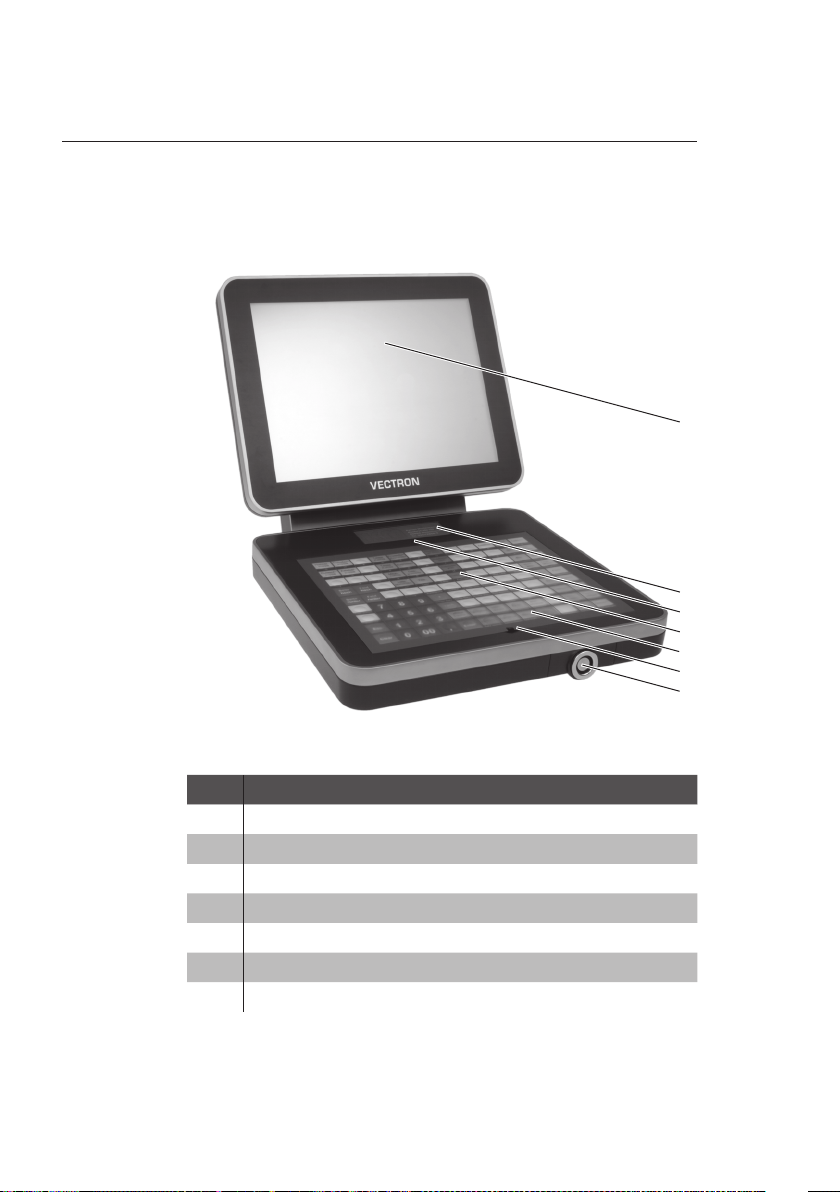
5.2.1. Vario II front view
1
2
3
4
5
6
7
30
Fig. 2: Vario II front view
Pos. Designation
1 Touch screen
2 Compartment for Vectron dealer information
3 Brightness sensor
4 Keyboard film
5 108 keys
6 Keyboard bar
7 Operator lock
Page 31

Touch screen pos. 1
Via the touch screen you enter data to Vario II using a
touch pen or your fingers.
Compartment for Vectron dealer information pos. 2
Your Vectron dealer should have inserted a card with contact information to this compartment.
Brightness sensor pos. 3
The brightness sensor meters the illuminance and controls
the display brightness.
Keyboard film pos. 4
Via the flat keyboard you enter data to the Vario II by
pressing the keys. Underneath the keyboard film a sheet is
inserted, which illustrates the functions.
Keys pos. 5
The 108 keys are allocated to the functions that you can
carry out by pressing them.
EN
Keyboard bar pos. 6
The keyboard bar serves for lifting the keyboard film.
Operator lock pos. 7
By means of an operator key you log in to Vario II via the
operator lock.
31
Page 32

VECTRON POS VARIO II
5.2.2. Vario II rear view
5
4
1
2
3
Fig. 3: Vario II rear view
32
Pos. Designation
1 Customer display port cover
2 Hinge
3 Loudspeaker opening
4 Display housing rear
5 Display housing front
Page 33

Customer display port cover pos. 1
Behind this cover you find the port for a customer display,
which you can purchase as accessory.
Hinge pos. 2
The hinge connects display housing and keyboard housing. It serves for tilting the housing in order to adjust the
display to your angle of view.
Loudspeaker opening pos. 3
A loudspeaker is mounted behind this opening. Via this
loudspeaker the Vario II can play system sounds for example.
EN
33
Page 34

VECTRON POS VARIO II
4 36
1
7
5
5.2.3. Vario II bottom view
Fig. 4: Vario II bottom view
2
34
Pos. Designation
1 Serial number label
2 Two USB ports
3 Keyboard housing top
4 Keyboard housing bottom
5 Interface label
6 Insert for operator lock
7 On/Off switch
Page 35

Serial number label pos. 1
The serial number label serves for unambiguous identification of the Vario II. The label contains the product designation and the serial number of the Vario II.
USB ports pos. 2
Via the USB ports you can connect external devices and
storage media to the Vario II.
Interface label pos. 5
The interface label informs you about the designation of
interfaces and their functions.
Insert for operator lock pos. 6
The operator lock is mounted to this insert. Your Vectron
dealer can remove the insert from the keyboard housing.
Your Vectron dealer can remove the operator lock from the
insert and replace it by another operator lock.
On/Off switch pos. 7
EN
The On/Off switch serves for switching on and off the
Vario II.
35
Page 36

VECTRON POS VARIO II
5.2.4. Ports and connections detailed view
21 43 5 6
8
Fig. 5: Ports and connections detailed view
Pos. Designation
1 Six USB ports
2 Network port
3 Six serial ports
4 Audio connection
5 Power connection
6 Two cash drawer ports
7 SD-card slot
8 SIM-card slot; optional
7
36
Page 37

USB ports pos. 1
Via the USB ports you can connect external devices and
storage media to the Vario II.
Network port pos. 2
To the network port you can connect a network cable.
Serial ports pos. 3
Via the serial ports you can connect external devices to
Vario II.
Audio connection pos. 4
To the audio port you can connect stereo loudspeakers,
e.g. for playing system sounds.
Power connection pos. 5
The power plug of the Vectron PS30 is connected to the
power supply.
Cash drawer ports pos. 6
EN
To the cash drawer ports you can connect up to four cash
drawers with a Y-cable.
SD-card slot pos. 7
To the SD-card slot you can insert an SD- or SDHC-card,
e.g. for storing data.
SIM-card slot pos. 8
To the optional SIM-card slot you can insert a SIM-card,
which for example encrypts data.
37
Page 38

VECTRON POS VARIO II
5.2.5. Power supply Vectron PS30
4
3
Fig. 6: Power supply Vectron PS30
Pos. Designation
1
Power cable
2
Power cable plug
3
Female connector
4
Serial number label
1
2
38
Page 39

Power cable plug pos. 2
The power cable plug is put into the power connection of
Vario II.
Female connector pos. 3
The female connector of the power cord is put into the
mains plug.
Serial number label pos. 4
The serial number label serves for unambiguous identification of the power supply Vectron PS30. The label contains
the product designation and the serial no. of the Vectron
PS30.
EN
39
Page 40

VECTRON POS VARIO II
5.2.6. Power cord
2
Fig. 7: German power cord
2
Fig. 8: English power cord
1
1
1
40
2
Fig. 9: American power cord
Pos. Designation
1
Female connector
2
Safety plug
Page 41

Female connector pos. 1
The female connector is put into the mains plug of the
power supply Vectron PS30.
Safety plug pos. 2
The safety plug is put into a grounded socket, which is protected by a fault current circuit breaker. The safety plug
may differ from the one shown in the figure.
EN
41
Page 42

VECTRON POS VARIO II
5.3. Dimensions
338
(13,3")
375
(14,8")
308
(12,1")
Fig. 10: Vario II (dimensions in millimetres and inch)
197
(7,8")
536
(21,1")
361
(14,2")
42
Page 43

6. Starting
This chapter tells you how to start the Vario II.
Your Vectron dealer should have programmed and configured the
Vario II POS system for your prior to starting. He should support
you with the starting.
Prior to starting your Vectron dealer should train you with the
operation of Vario II. Furthermore he should inform you about
the functions of the Vario II POS system and adjust them to your
demands.
Useful and important functions are for instance:
• configuring acoustic and optical signals
• entering PLUs to PLU tables
• configuring the graphical user interface
• configuring user passwords
• configuring reports
• configuring data backup
• saving energy
• operating the Vario II POS system
• using the Vario II POS system in wireless networks
• integrating and using the Vario II POS system in a network
• connecting external devices to the Vario II
EN
43
Page 44

VECTRON POS VARIO II
6.1. Set up of Vario II
This chapter tells you how to set up Vario II, how to connect it to the power supply and how to connect devices to
Vario II.
6.1.1. Selecting the setup site for Vario II
This chapter informs you about the setup site for Vario II.
a
• Set up the Vario II in a well-ventilated room with a temperature between 0 and 40 °C.
• Do not cover the Vario II.
• Select the setup site so that the Vario II is not exposed
to direct sunlight.
• Place the Vario II on a stable, even surface with sufficient space.
• Never place the Vario II next to e.g. sinks or dispensing systems to avoid that liquids are poured over the
Vario II, power supply Vectron PS30 and power cord.
• Lay out the cables so that they are not under tension.
• Lay out the cables so that you do not trip over them.
NOTICE
X
Never set up the power supply and
the POS system other than described
in the instructions
You can damage power supply and
•
POS system
site is not stable.
.
if for instance the setup
44
Page 45

6.1.2. Connecting Vario II to the power supply
This chapter tells you how to connect the Vario II to the
power supply.
• Place the Vario II to a smooth, stable and even surface
with sufficient space.
• Put the power cable plug of the supplied power supply
Vectron PS30 to the power connection of Vario II.
Fig. 11: Putting the power cable plug to the power connec-
tion
EN
45
Page 46

VECTRON POS VARIO II
• Place the Vario II to a site as described in chapter 6.1.1
“Selecting the setup site for Vario II” on page 44 .
• Put the female connector of the power cord into the
mains plug of the power supply.
Fig. 12: Putting the female connector to the mains plug
46
• Put the safety plug of the supplied power cord into a
grounded socket with alternating voltage between 110
and 240, which is protected by a fault current circuit
breaker.
Page 47

6.1.3. Connecting devices to Vario II
This chapter tells you how to connect devices to the
Vario II.
• Make sure to connect only Vectron-approved devices to
Vario II.
Your Vectron dealer will tell you which
devices may be connected to the
Vario II.
i
• Make sure to lay out the cables so that they are not
under pressure.
• Make sure to lay out the cables so that you do not trip
over them.
EN
47
Page 48

VECTRON POS VARIO II
6.2. Placing the insert
This chapter tells you how to place the insert underneath
the keyboard film.
i
• Lift the keyboard film using the keyboard bar.
• Insert the sheet and align it to the quadrats printed on
the keyboard film.
Your Vectron dealer should have provided you with suitable inserts that match
the user interface of Vario II.
48
Fig. 13: Lifting the keyboard film and aligning the insert
Page 49

6.3. Adjusting the display
This chapter tells you how to adjust the display of Vario II.
A CAUTION
X
Never put your fingers into the gap
between display housing and hinge.
You can crush your fingers since
•
q
• Hold the keyboard housing of Vario II with one hand and
the display housing with the other.
• Adjust the display to your field of vision by tilting the
housing.
the gap becomes smaller when the
display housing is moved.
EN
Fig. 14: Adjusting the display
49
Page 50

VECTRON POS VARIO II
6.4. Adjusting the customer display
This chapter tells you how to adjust the customer display.
• Hold the display housing of Vario II with one hand and
the housing of the customer display with the other.
• Adjust the customer display by tilting the housing to
your field of vision.
50
Page 51

7. Operation
This chapter tells you how to use the Vario II in normal mode.
7.1 . Switching the Vario II on and off
This chapter tells you how to switch on and off the Vario II.
7.1.1. Switching on the Vario II
If the Vario II was started as described in chapter 6 “Starting” on page 43 , you can switch it on.
• Shortly press the On/Off key to switch on the Vario II.
EN
Fig. 15: Switching on the Vario II
51
Page 52

VECTRON POS VARIO II
7.1 . 2. Switching off the Vario II
This chapter tells you how to switch off the Vario II.
• Shortly press the On/Off key to switch off the Vario II.
Fig. 16: Switching off the Vario II
52
Page 53

7.2. Entering data to the Vario II
This chapter tells you how to enter data to the Vario II
via touch screen and flat keyboard. You are also informed
about the display elements.
Your display layout may differ from the one shown in this
manual, depending on programming and configuration of
your Vario II. Explanations in this user manual refer to the
Vectron hospitality user interface with version 1.0.1.
Prerequisite for entering data to the Vario II is that Vario II
was started as described in chapter 6 “Starting” on page
43 . You also have to switch on the Vario II as described
in chapter 7.1.1 “Switching on the Vario II” on page 51.
EN
53
Page 54

VECTRON POS VARIO II
7.2.1. Entering data via the flat keyboard
This chapter tells you how to enter data to the Vario II via
flat keyboard.
• Touch the keys of the keyboard film with your fingers.
54
Fig. 17: Entering data via flat keyboard
7.2.2. Entering data via touch screen
This chapter tells you how to enter data to the Vario II via
touch screen.
Page 55

• Touch the buttons of the touch screen with a touch pen
or your fingers.
7
6
5
4
Fig. 18: Entering data via touch screen
1
2
3
EN
Pos. Designation
1 Status display
2 PLU selection
3 Open GC display
4 Input field
5 Info field
6 Balance display
7 Receipt-, invoice- and guest check display
55
Page 56

VECTRON POS VARIO II
Status display pos. 1
Displays for example the date, time and the currently
logged in operator.
PLU selection pos. 2
Here you select the PLUs that are stored in PLU programming of the Vario II and are shown on the user interface.
Open GC display pos. 3
Shows the currently open guest checks and the total sales
of customers for the single GCs.
Input field pos. 4
Displays for example the entries you make on the numeric
pad. Furthermore, the price of the last booked PLU is displayed.
Info field pos. 5
56
Displays for example media-related information, e.g.
whether the customer paid cash or by credit card, or the
change that a customer gets.
Balance display pos. 6
The balance display shows in field “Receipt” the sum of
current receipt bookings. The field “Sales” shows the sum
of all PLUs booked to a guest check.
Receipt-, invoice- and GC display pos. 7
Displays for example the entered PLUs, the invoice for a
customer and the bookings for an open GC.
Page 57

7.3. Sign in to Vario II
This chapter informs you about the sign in procedure and
tells you how to sign in to Vario II.
Buttons that are mentioned in this chapter and that can be displayed as graphical elements, are shown in chapter 13
“Icons” on page 85 .
i
Depending on the programming of your Vario II you have
to sign in to the POS system. Only then you can enter PLUs
for example.
The Vectron POS software stores the entries and assigns
them to the respective operator. You can assign access
rights for every operator, which determine the functions
for which he is authorized.
There are different ways for sign in to Vario II. If you have
an operator key that you want to use for sign in please continue reading in chapter 7.3.2 “Sign in via operator key”
on page 59 . If you do not have an operator key, please
continue in chapter 7.3.1 “Sign in via operator button” on
page 58 .
EN
The POS system may be programmed in that way that you
can use both methods for sign in.
57
Page 58

VECTRON POS VARIO II
7.3.1. Sign in via operator button
Carry out the following steps if your Vario II was programmed for sign in via operator button.
• Press the <Functions> key on the keyboard film.
• Press the button <Mod. functions 2> on the touch screen.
• Enter the operator number to the numeric pad of the
keyboard film.
• Press the <Operator> button on the touch screen to sign
in this operator.
i
• Enter the secret code to the numeric pad of the keyboard film if it is requested.
• For confirmation press the <Enter> key on the keyboard
film to sign in this operator.
The profile of the selected operator can
be protected with a secret code. For sign
in you have to enter the secret code.
58
Page 59

7.3.2. Sign in via operator key
This chapter informs you about an operator lock system,
how it works and what you have to consider when using the
operator lock system.
Your Vario II is delivered with an operator lock system. It
consists of two elements: the operator lock, referred to as
lock in the following, and the operator key, referred to as
key in the following.
The lock is mounted to your Vario II. Your Vectron dealer
should have handed over the ordered keys on delivery.
For Vario II you can order three operator lock systems, one
of which is mounted to your Vario II. Standard is the operator lock Vectron L10.
Designation Lock Key
Lock and key
Vec tron L10
EN
Lock and key
Vectron L20
Lock Vectron L30
and key Addimat
59
Page 60

VECTRON POS VARIO II
Each operator has assigned rights in the POS system. This
means that you are for example allowed to void PLUs and
to open the guest checks of other operators. The rights are
stored in tables. These tables will be called rights tables in
the following. Your rights, too, are stored in rights tables.
Your key has an unambiguous number. This number is
stored in the rights table. This assignment helps Vectron
POS software recognize who signs in to the POS system.
If you approach the key to the lock, the number is transferred from the key to the POS system. The rights that
are stored for you in the rights table are enabled. You can
work with the POS system.
Carry out the following steps if your Vario II was programmed for sign in via operator key.
60
Page 61

• Approach the key to the operator lock.
Fig. 19: Approaching the key to the operator lock
The profile of the selected operator can
be protected with a secret code. For sign
in you have to enter the secret code.
i
• Enter the secret code to the numeric pad of the keyboard film if it is requested.
• For confirmation press the <Enter> key on the keyboard
film to sign in this operator.
EN
61
Page 62

VECTRON POS VARIO II
7.4. Sign out from the Vario II
This chapter tells you how to sign out from the Vario II.
i
i
7.4.1 . Sign out via operator button
Buttons that are mentioned in this chapter and that can be displayed as graphical elements, are shown in chapter 13
“Icons” on page 85 .
You should sign out from the Vario II if
you do not use the POS system in order
to avoid entries being made by others.
62
Carry out the following steps if your Vario II was programmed for sign out via operator button.
• Press the <Functions> key on the keyboard film.
• Press the button <Mod. functions 2> on the touch screen.
• Press the <Operator> button on the touch screen to sign
out this operator.
Page 63

7.4.2. Sign out via operator key
Carry out the following step if your Vario II was programmed for sign out via operator key.
• Approach the Vectron L10 key to the lock if the Vectron
L10 lock is mounted to the Vario II.
• Remove the L20 key if the Vectron L20 lock is mounted
to the Vario II.
• Remove the Addimat key if the Vectron L30 lock is
mounted to the Vario II.
EN
Fig. 20: Approaching and removing the key
63
Page 64

VECTRON POS VARIO II
7.5. Working with guest checks
This chapter informs you about the guest check (GC) function. Whether or not you can use this function depends on
programming and configuration of your Vario II.
The GC function serves for separate storage of bookings
for several customers. It is useful for instance in hospitality, to store food and drinks separately for each table in a
restaurant.
Your Vectron dealer can program and configure the number of GCs and operators according to your requests.
i
Buttons that are mentioned in this chapter and that can be displayed as graphical elements, are shown in chapter 13
“Icons” on page 85 .
64
7.5.1. Opening a GC
In order to store GC bookings you first have to open a GC.
GCs, for which an invoice was not yet generated, can be
opened again with this function.
• Enter the GC number to the numeric pad of the keyboard
film to open the GC.
• Press the <GC> button on the keyboard film.
A GC that was already open can be
opened again by pressing the GC button
in the Open GC display.
i
Page 65

7.5.2. Booking PLUs to a guest check
This chapter tells you how to enter PLUs, which the customers ordered, to a GC.
• Open the GC to which you want to book the PLUs as described in chapter 7.5.1 “Opening a GC” on page 64 .
• Press the keys on the keyboard film or the buttons on
the touch screen on which PLUs are stored.
7.5.3. Closing a GC
When you close a GC, bookings for this GC are stored.
There are several ways to close a GC.
• Press the <GC> button on the keyboard film or open a
new GC as described in chapter 7.5.1 “Opening a GC” on
page 64 , to close the currently open GC.
EN
65
Page 66

VECTRON POS VARIO II
7.5.4. Finalizing a GC
With this function you generate an invoice, move the bookings to the booking memory and close the GC.
• Open the GC to be finalized as described in chapter 7.5.1
“Opening a GC” on page 64 .
• Enter the amount you got from the customer to the
numeric pad.
• Press the <Cash> key or select another media to generate an invoice.
i
i
The POS system moves the bookings to
the booking memory, closes the GC and
displays the amount that you have to
return to the customer.
After opening the GC you can directly
press <Cash> or select another media.
This is useful when you get the exact
amount from the customer.
66
Page 67

7.5.5. Splitting PLUs of a guest check to invoice
The GC split function serves for generating separate invoices for one GC. This is useful if guests of one table want
to pay separately.
The GC split function can only be carried out if all PLUs of a GC have been
booked. Close the open GC as described
i
• Open the GC to be split as described in chapter 7.5.1
“Opening a GC” on page 64 .
• Press the <Payment> key on the keyboard film to display
the payment surface.
• Press the <GC split> button on the touch screen.
• Select the PLUs to be split.
• Press the <Cash> button or select another media to gen-
erate an invoice for the split PLUs.
in chapter 7.5.3 “Closing a GC” on page
65 .
EN
67
Page 68

VECTRON POS VARIO II
7.5.6. Splitting single PLUs of a guest check to another guest check
The GC split function serves for transferring single PLUs to
another guest check. This is useful if some guests want to
change the table.
i
• Open the GC to be split as described in chapter 7.5.1
“Opening a GC” on page 64 .
• Press the <Payment> key on the keyboard film to display
the payment surface.
• Enter the GC no. to which the PLUs are to be transferred.
• Press the <GC split> button on the touch screen.
• Select the PLUs to be split.
• Press the <GC> button on the keyboard film to split the
selected PLUs.
The GC split function can only be carried out if all PLUs of a GC have been
booked. Close the open GC as described
in chapter 7.5.3 “Closing a GC” on page
65 .
68
Page 69

7.5.7. Moving all PLUs of one guest check to another guest check
The move GC function serves for moving all PLUs of one GC
to another.
• Open the GC to be moved as described in chapter 7.5.1
“Opening a GC” on page 64 .
• Press the <Payment> key on the keyboard film to display
the payment surface.
• Enter the GC no. to which all PLUs are to be moved.
• Press the <GC move> button on the touch screen to move
the guest check.
7.5.8. Transferring a guest check to another operator
The transfer GC function serves for transferring a guest
check to another operator. This function is useful for a
shift change for example.
• Open the GC to be transferred as described in chapter
7.5.1 “Opening a GC” on page 64 .
• Press the <Functions> key on the keyboard film.
• Press the <Mod. functions 2> key on the touch screen.
• Press the <Shift change> button on the touch screen.
• Select an operator from the list to transfer the GC to
him.
EN
69
Page 70

VECTRON POS VARIO II
7.6. Working with hold buffers
This chapter informs you about the hold buffer function.
Whether or not you can use this function depends on programming and configuration of your Vario II.
The hold buffer function serves for separate storage of
bookings made by several operators. This function is useful
for example in a bakery, if only one POS system is available
for several users. Another scenario would be the supermarket, where a customer forgot his purse in the car. The
already booked PLUs are stored in a hold buffer so that
other customers can be served until the first returns with
his money.
Hold buffers allow several operators simultaneously to
work at one POS system. The first operator opens a hold
buffer by pressing the respective button. He then signs in
and enters the PLUs. The operator has not yet finalized the
booking. If now a second operator wants to use the POS
system, he presses another hold buffer button, signs in and
enters the PLUs. Both operators can change between these
hold buffers. The operators’ entries remain in the respective hold buffer until payment.
70
Your Vectron dealer can program and configure the
number of hold buffers and operators according to your
requests.
Page 71

7.7. Working with reports
This chapter informs you about the report function. Whether or not you can use this function depends on programming and configuration of your Vario II.
In reports you can evaluate data that was stored in the
POS system. The Vectron POS software provides several
standard reports. You can display and print PLU- and operator reports for example. A PLU report can contain e.g.
PLU numbers, PLU names, the number of sold PLUs, the
sales per PLU and the total sales. An operator report can
contain e.g. the proceeds of the operators and the sales
per customer.
You can create two types of reports with Vectron POS
software: X-reports and Z-reports. X-reports are intermediate reports, where the data is not deleted from the booking memory. Z-reports are final reports, where the data is
deleted from the booking memory.
Your Vectron dealer can program and configure reports
according to your requests.
EN
71
Page 72

VECTRON POS VARIO II
7.8. Void and Correction
This chapter informs you about the void function. Whether
or not you can use this function depends on programming
and configuration of your Vario II.
You can cancel bookings if for instance an operator made
false entries. Furthermore, you can program and configure
the Vario II so that PLUs are cancelled and the respective
invoice is corrected, if a customer returns items.
7.9. Restarting Vario II
Restart the Vario II by switching it off and on again.
• Shortly press the On/Off key to switch off the Vario II.
• Shortly press the On/Off key to switch on the Vario II.
72
Fig. 21: Switching on and off Vario II
Page 73

8. Shut down
This chapter tells you how to shut down the Vario II.
Shut down the Vario II if you do not use it for a longer period.
• Shortly press the On/Off key to switch off the Vario II.
Fig. 22: Switching off the Vario II
• Unplug the safety plug of the power cord from the socket.
EN
73
Page 74

VECTRON POS VARIO II
• Place the Vario II on a smooth, stable and even surface with
sufficient space.
• Remove the safety plug of the power cord from the power connection of Vario II.
Fig. 23: Unplugging the power plug
• Unplug all cables that are connected to the Vario II.
74
Page 75

• Unplug the female connector of the power cord from the mains
plug of the power pack.
Fig. 24: Unplugging the female connector
• Pack the Vario II, power supply Vectron PS30 and power cord in
the original packaging.
• Store the Vario II in a room where the temperature is between
-10 and 50 °C.
EN
75
Page 76

VECTRON POS VARIO II
9. Errors, possible reasons and troubleshooting
This chapter informs you about possible reasons for errors that
occur when operating the Vario II and tells you how to remove
them yourself. Please contact your Vectron dealer if you cannot
solve the problem yourself.
Errors Possible reasons Troubleshooting
Vario II cannot be
switched on.
The Vario II POS
system does not react to your entries.
76
The safety plug is
not put into a live
socket.
The power cable
plug of the power
supply PS30 is
not put to the
power connector of
Vario II.
The On/Off key is
damaged.
The power supply
Vectron PS30 is
damaged.
The Vario II is damaged.
The signed-in operator is not authorized for the respective function.
Put the safety
plug of the supplied power cord
into a grounded
socket with alternating voltage
between 110 and
240 volt and which
is protected with a
fault current circuit
breaker.
Put the power cable
plug of the power
supply PS30 to the
power connector of
Vario II.
Co nt act your
Vectron dealer.
Co nt act your
Vectron dealer.
Co nt act your
Vectron dealer.
Co nt act your
Vectron dealer.
Page 77

Errors Possible reasons Troubleshooting
Vario II does not
display anything.
The Vario II processes other entries
than those made on
the touch screen.
The touch screen is
not calibrated.
Vectron POS software has a malfunction.
Programming and
configuration of
Vario II is faulty.
The touch screen is
damaged.
The flat keyboard is
damaged.
Vario II is switched
off.
The screen saver is
active.
Vectron POS software has a malfunction.
The PS30 is damaged.
Vario II is damaged. Contac t you r
The touch screen is
not calibrated.
Co nt act your
Vectron dealer.
Restart the Vario II
as described in
chapter 7.9 “Restarting Vario II” on
page 72 .
Co nt act your
Vectron dealer.
Co nt act your
Vectron dealer.
Co nt act your
Vectron dealer.
Press the On/Off
key as described
in chapter 7.1.1
“Switching on the
Vario II” on page
51 .
Touch the screen
with a finger or the
touch pen or press
a key on the keyboard film.
Co nt act your
Vectron dealer.
Co nt act your
Vectron dealer.
Vectron dealer.
Co nt act your
Vectron dealer.
EN
77
Page 78

VECTRON POS VARIO II
Errors Possible reasons Troubleshooting
The Vario II processes other entries
than those made on
the touch screen.
The sound reproduction at the
Vario II does not
work.
Sign in by key via
the operator lock to
the Vario II is not
possible.
Vectron POS software has a malfunction.
Programming and
configuration of
Vario II are faulty.
The touch screen is
damaged.
Loudspeakers are
connected but the
volume is too low.
The sound reproduction was not
programmed and
configured.
Loudspeakers are
damaged.
The audio connection is damaged.
The operator lock
was not programmed and configured.
Operator lock or
operator key are
damaged.
Restart the Vario II
as described in
chapter 7.9 “Restarting Vario II” on
page 72 .
Co nt act your
Vectron dealer.
Co nt act your
Vectron dealer.
Remove the loudspeakers or increase their volume.
Co nt act your
Vectron dealer.
Exchange the loudspeakers.
Co nt act your
Vectron dealer.
Co nt act your
Vectron dealer.
Co nt act your
Vectron dealer.
78
Page 79

10. Service and maintenance
This chapter tells you how to clean the Vario II and informs you
how to get technical support.
10.1. Cleaning
This chapter tells you how to clean the Vario II.
NOTICE
Caustic cleansers can damage the
surfaces
X
Do not use caustic cleansers
X
a
Only use mild cleansers or water for
cleaning
10.1.1. Cleaning housing and display
Clean the housing of Vario II and the display with a flufffree cloth. You can dampen the cloth with a mild, residuefree cleanser or water.
10.1.2. Cleaning the contacts
Clean the contacts of Vario II with a cotton bud and without applying pressure.
10.2. Maintenance
Any maintenance work at the Vario II must exclusively be
carried out by your Vec tron dealer.
EN
79
Page 80

VECTRON POS VARIO II
10.2.1. Exchanging the insert
This chapter tells you how to exchange the insert of
Vario II.
i
• Lift the keyboard film by means of the keyboard bar.
• Remove the insert.
• Insert the sheet and align it to the quadrats printed on
the keyboard film.
You get new inserts from your Vectrondealer.
80
Fig. 25: Lifting the keyboard film and aligning the insert
Page 81

10.3. Contacting the customer service
Please contact your Vectron dealer in case of questions or
should you require assistance for operating the Vario II.
EN
81
Page 82

VECTRON POS VARIO II
11. Disposal
Vectron Systems AG takes back waste electric and electronic
equipment that has been used for commercial purposes and that
was produced by or on behalf of the company, consistent with
article 9 of directive 2002/96/EC, last changed by directive
2003/108/EC. The company will dispose of the waste electric and
electronic equipment properly.
The legal obligation applies for devices, that will be put on the
market after August 13, 2005. In addition, the manufacturer
extends this obligation to all devices that have been put on the
market as of January 1, 2004.
The Vario II and the power supply Vectron PS30 with power cord
must not be disposed of together with household waste.
Please send back waste electric and electronic equipment that
was produced by or on behalf of Vectron Systems AG prepaid and
marked “Waste electric and electronic equipment” to Vectron
Systems AG in the original packaging.
82
WEEE- Reg.-no . D E 91733199
Page 83

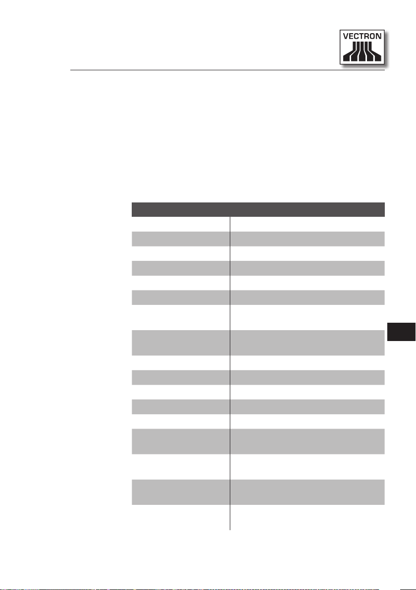
12. Glossary
This chapter explains the terms that are used in context with the
Vario II.
Term Definition
Bar code Information, which consists of bars with
Booking memory Memory in which every booking of the op-
Button A button is programmed in the POS system
Flash memory Memory that keeps data even after the volt-
Flat keyboard Input device, which releases functions in the
GC server POS system, which is responsible for central
Icon Pictograph used in graphical user interfaces.
LCD Liquid Crystal Display
Payment Method for finalizing an invoice. Media are
Payment interface
POS Point Of Sale
Registration interface
Thin Film Transistor (TFT)
varying widths and spaces of parallel lines.
The bar code represents data, which e.g. the
POS system can decode.
erators is stored.
and releases commands. The programmed
commands can be called via touch screen or
keyboard of the POS system.
age supply was switched off.
POS system when an operator presses the
keys on the plastic film of the POS system.
guest check administration in the network.
When touching or clicking on icons you can
call functions of the Vectron POS software.
for example cash and credit card payment.
Displayed screen, on which you can effect
payments with various media for example.
Displayed screen, on which you can book
PLUs to guest checks for example.
Electronic component for control of screens.
EN
83
Page 84

VECTRON POS VARIO II
Term Definition
Touch screen Input device which releases functions in the
POS system, when an operator touches the
buttons on the display.
User interface All display elements and buttons on the
screen, which serve for display of information or execution of functions.
X-rep ort Intermediate report, where data is not de-
leted from the memory.
Z-r ep ort Final report, where data is deleted from the
memory.
84
Page 85

13. Icons
Icons are pictographs on the display of the Vario II. Icons shown
on the display are designated buttons. A touch of the display button calls functions, like e.g. generating an invoice.
This chapter lists some of the icons integrated in Vectron POS
software and explains their meaning. You can load self-created
icons to Vectron POS software, e.g. for product groups or products.
Please contact your Vectron dealer for questions and requests
concerning programming and configuration.
EN
85
Page 86

VECTRON POS VARIO II
Overview of icons that are integrated in Vectron POS software:
The numbering of lines and columns is meant to help you with the
designation of icons in this table. The icon no. of each icon that is
used in Vectron POS software can be found in the detailed table
starting page 87.
1 2 3 4 5 6 7 8 9
1
2
3
4
5
86
6
7
8
9
10
11
Page 87

Meaning of icons that are integrated in Vectron POS software:
Icon no. Icon Meaning
10
1
2
3
4
5
6
7
Vectron POS
Centered
Left assigned
Right assigned
Enter
Field up
Field down
EN
8
9
Cursor left
Cursor right
Page up
11
12
13
14
Page down
Field left
Field right
Shift
87
Page 88

VECTRON POS VARIO II
Icon no. Icon Meaning
15
16
17
18
19
20
21
22
23
24
Shift lock
Editor
New record
Delete records
Print
Next record
Prev. record
Goto record
Select
Mark
88
25
26
27
28
29
Mark
Browser / Mask
Search by text
Send
Load
Page 89

Icon no. Icon Meaning
30
31
32
33
34
101
102
103
104
105
Store
Network
Clear
Esc
Mode
Takeaway
Cancel receipt
Duplicate receipt
EN
Guest counter
In-house
106
107
108
109
110
No invoice
Operator
Manager func. Only
Open GC/operator
Seat number
89
Page 90

VECTRON POS VARIO II
Icon no. Icon Meaning
111
112
113
114
115
116
117
118
119
120
PLU
Invoice
Load invoice
Recall invoice
Duplicate GC
Split by seat no.
Void
Void last entry
Check
GC 0
90
121
122
123
124
125
GC split
Tra nsfer GC
Check move
Table map
Edit GC text
Page 91

Icon no. Icon Meaning
126
127
128
129
130
131
132
133
134
135
X reports
Z reports
Subtotal GC
Subtotal
Deposit
Paid out
Operator report
Receipt on
EN
Receipt off
Data entry
136
137
138
139
140
Print format shift
Received amount
VIP sale
Journal
Price
91
Page 92

VECTRON POS VARIO II
Icon no. Icon Meaning
141
142
143
201
202
401
402
403
404
405
Table reservations
Department DPT
Department WG
Cash
Media no.
Cold drinks
Hot drinks
Side dishes
Beer
Icecream
92
406
407
408
409
410
Fish
Meat
Beverages
Main dishes
Desserts
Page 93

Icon no. Icon Meaning
411
412
413
414
415
416
Pizza
Spirits
Starters
Wine
Vegetables
Salad
EN
93
Page 94

VECTRON POS VARIO II
14. EC Declaration of conformity
Manufacturer Vectron Systems AG
Willy-Brandt-Weg 41
48155 Muenster, Germany
Device type Stationary POS System
Type designation Vectron POS Vario II
The manufacturer declares that the above designated product
complies with the fundamental standards of directives 2004/108/
EC and 2006/95/EC when used as directed.
Applied standards
• EN 55022:2006 + A1:2007 class A
• EN 55024:1998 + A1:2001 + A2:2003
• EN 60950-1:2006 + A11:2009
• EN 61000-3-2:2006 + A1:2009 + A2:2009
• EN 61000-3-3:2008
94
Muenster, 8.12.2011
Jens Reckendorf
Member of the Board
Thomas Stümmler
Member of the Board
Page 95

15. Accessories
At this point we would like to inform you about the accessories
you can purchase for the Vario II. More information and the technical data for accessories are available on the Internet at www.
vectron.de.
Please address your questions concerning our products to your
Vectron dealer.
15.1. Operator lock systems
You can mount various operator lock systems to Vario II.
You can use an operator lock system for sign in to Vario II.
15.1.1. Operator lock Vectron L10
The Vectron L10 operator lock is mounted to the operator
lock insert, which is supplied together with Vario II.
Fig. 26: Operator lock Vectron L10
EN
95
Page 96

VECTRON POS VARIO II
15.1.2. Operator lock Vectron L20
The Vectron L20 operator lock is mounted to the operator
lock insert, which is supplied together with Vario II.
Fig. 27: Operator lock Vectron L20
15.1.3. Operator lock Vectron L30
The Vectron L30 operator lock is mounted to the operator
lock insert, which is supplied together with Vario II.
96
Fig. 28: Operator lock Vectron L30
Page 97

15.2. Customer displays
Vectron customer displays serve for showing texts and
graphics, e.g. for informing your customers about special
offers.
15.2.1. Customer display Vectron C56
The Vectron C56 customer display is mounted to the display housing of the POS system or to a stand, which can be
ordered in two different sizes. The customer display has a
screen diagonal of 13.16 cm (5.2"), on which 2 x 20 characters can be shown. It has a resolution of 240 x 64 pixels
and is capable for graphic representation.
EN
Fig. 29: Customer display C56
97
Page 98

VECTRON POS VARIO II
15.2.2. Customer display Vectron C75
The Vectron C75 customer display has a screen diagonal of
17.78 cm (7"). It can show texts and graphics. The C75 has
a resolution of 800 x 480 pixels.
Fig. 30: Customer display C75
98
Page 99

15.3. Touch pen s
The touch pens serve for entering data via the touch
screen of Vario II.
15.3.1. Vectron Touch pen
The Vectron touch pen serves for entering data via the
touch screen of Vario II. The touch pen is made of plastic.
Fig. 31: Vectron Touch pen
15.3.2. Multifunction touch pen
The touch pen serves for entering data via the touch
screen of Vario II. The multifunction touch pen has an integrated ball pen refill. By turning the cap you can change
between writing- and touch function.
Fig. 32: Multifunction touch pen
EN
99
Page 100

VECTRON POS VARIO II
16. Other Vectron products
This chapter tells you which other Vectron products you can purchase in addition to the Vario II. For current and detailed information please see the Internet at www.vectron.de.
Please address your questions concerning our products to your
Vectron dealer.
16.1. Stationary POS systems
The stationary POS systems can be used as single station
systems. Furthermore, they can be used as server in a
network, for data exchange between mobile and stationary systems for example. All mobile and stationary POS
systems are compatible thanks to the uniform Vectron POS
software.
100
 Loading...