

Page 1

User
manual
HW 90196
and components
VECTRON Systems AG
Version 1.0
Page 2
Vectron User manual
© Höft & Wessel AG
Subject to amendment, errors excepted HW90195UserMan.doc 1.0 02.02.2001 Lin
page 2/70
Document informationen
Project: Vectron
Type of Document: User manual
Version: 1.0
Date of issue: 02.02.2001
Author: Nicolett Linke / Lin
Höft & Wessel AG, Hannover
Changes:
Version: Revison: Date By
01.00 Translation of german version 1.2 02.02.2001 atü
This document and its contents shall not be reproduced or transferred in any form without express permission. Compensation will be claim ed for an y
infringement. All rights reserved in the event of patenting or registration of utility models.
Page 3

User manual Vectron
© Höft & Wessel AG
page 3/70
Lin 02.02.2001 1.00 HW90195UserMan.doc Subject to amendment, errors excepted
Table of contents
1. General...............................................................................................................................7
1.1 Important comments for application!................................................................................8
1.2 Bring-in service (repair of devices)...................................................................................9
1.2.1 Special case plug-in in ID-000 format at initial delivery ............................................9
1.2.2 Special case plug-in in ID-000 format at repair........................................................9
2. Graphik presentation and keyboard ..............................................................................10
2.1 HW 90196 frontal view...................................................................................................10
2.2 Keyboard functions........................................................................................................11
2.2.1 Switch on/off HW 90196........................................................................................12
2.2.2 KEYBOARD-CLICK-function (keyboard beep) during standard mode...................12
3. Technical data .................................................................................................................13
3.1 Hardware.......................................................................................................................13
3.2 Software........................................................................................................................14
3.3 Block diagram................................................................................................................15
3.4 Power consumption.......................................................................................................16
4. Power supply of HW 90196 with accu block HW 19196 ................................................ 17
4.1 Technical data ...............................................................................................................17
4.2 Charging condition of accu block ...................................................................................18
4.3 Replacing the accu block in HW 90196..........................................................................18
4.4 Maintenance of accu block ............................................................................................19
4.5 Disposal of used accus..................................................................................................19
5. Operating system............................................................................................................ 20
5.1 Operating system-basic menu .......................................................................................21
5.1.1 System-info-display...............................................................................................23
5.2 Warm start.....................................................................................................................24
5.3 Reset.............................................................................................................................24
5.4 Format FLASH-Disk .......................................................................................................25
5.5 Radio module configuration menu (DECT-menu)...........................................................26
5.5.1 Terminal................................................................................................................26
5.5.2 Functions...............................................................................................................26
5.5.3 Printer ...................................................................................................................28
5.6 Connection to a PC........................................................................................................29
5.7 Error messages of the operating system........................................................................31
Page 4

Vectron User manual
© Höft & Wessel AG
Subject to amendment, errors excepted HW90195UserMan.doc 1.0 02.02.2001 Lin
page 4/70
6. Printer HW 90195 ............................................................................................................ 32
6.1 Technical data...............................................................................................................33
6.1.1 Hardware.............................................................................................................. 33
6.1.2 Software................................................................................................................34
6.1.3 Block diagram....................................................................................................... 35
6.1.4 Power consumption .............................................................................................. 36
6.2 Functions ...................................................................................................................... 36
6.2.1 Operating modes .................................................................................................. 36
6.2.2 Function indication LEDs ...................................................................................... 37
6.2.3 Acoustic signals .................................................................................................... 37
6.3 Fonts............................................................................................................................. 38
6.3.1 Standard font 1..................................................................................................... 38
6.3.2 Standard font 2..................................................................................................... 40
6.4 Test printout.................................................................................................................. 42
6.5 Printer malfunction........................................................................................................ 42
6.6 Special features of printer.............................................................................................. 43
6.7 Changing paper reel of printer....................................................................................... 44
6.7.1 Comments about the thermopaper........................................................................ 45
6.8 Power supply with accu block HW 19195...................................................................... 46
6.8.1 Technical data ...................................................................................................... 46
6.8.2 Replacing accu block of printer HW 90195............................................................47
6.8.3 Recharging the accu blocks.................................................................................. 47
6.8.4 Maintenance and disposal ....................................................................................47
7. Base Station HW 8660 .................................................................................................... 48
7.1 Technical data...............................................................................................................49
7.1.1 Hardware.............................................................................................................. 49
7.1.2 Software................................................................................................................49
7.1.3 Block diagram....................................................................................................... 50
7.2 Power supply unit.......................................................................................................... 51
7.2.1 Technical data ...................................................................................................... 51
8. Plug-in in ID-000-format.................................................................................................. 52
8.1 Description.................................................................................................................... 52
8.2 Inserting the plug-in....................................................................................................... 53
Page 5

User manual Vectron
© Höft & Wessel AG
page 5/70
Lin 02.02.2001 1.00 HW90195UserMan.doc Subject to amendment, errors excepted
9. Connection of the HW 90196 and HW 90195 via radio transmission ...........................54
9.1 General..........................................................................................................................54
9.2 Technical architecture....................................................................................................55
9.3 Function diagram...........................................................................................................56
9.3.1 Initial logon of MDE ...............................................................................................56
9.3.2 Repeated logon of MDE........................................................................................56
10. Radio frequency transmission system according to FCC part 15 ...............................57
10.1 Purpose of the chapter...............................................................................................57
10.2 Abbreviations .............................................................................................................57
10.3 Overvie w....................................................................................................................57
10.3.1 Product HW 90196/US..........................................................................................57
10.3.2 Product HW 90195/US..........................................................................................57
10.3.3 Product HW 8660/US............................................................................................58
10.4 Radio frequency transmissi on....................................................................................58
10.4.1 Freq uency channels..............................................................................................58
10.4.2 Carri er modul ation.................................................................................................59
10.5 Multiplexing................................................................................................................59
10.5.1 Multiplexing in the Time Domain............................................................................59
10.5.2 Multiplexing in the Frequency Domain...................................................................59
10.5.3 Generic frequency hopping patterns......................................................................60
10.5.4 Hopping channels..................................................................................................62
10.5.5 Bearer position ......................................................................................................62
10.6 Medium Access Procedures.......................................................................................62
10.6.1 Synchronization.....................................................................................................62
10.6.2 Monitoring of the environment...............................................................................63
10.6.3 Setting up a connection.........................................................................................63
10.6.4 Connection maintenance.......................................................................................63
10.7 Interference avoidance strategies ..............................................................................64
10.7.1 Interference within the system...............................................................................64
10.7.2 Interference between two systems of the same type.............................................64
10.7.3 Interference from other sources.............................................................................65
10.7.4 Interference to other systems................................................................................65
10.8 Specific requirements from FCC chapter 15...............................................................66
10.8.1 15.203 Antenna requirement.................................................................................66
10.8.2 15.204 External radio frequency power amplifiers and antenna modifications.......66
10.8.3 15.205 Restricted bands of operation....................................................................66
10.8.4 15.207 Conducted limit..........................................................................................66
Page 6

Vectron User manual
© Höft & Wessel AG
Subject to amendment, errors excepted HW90195UserMan.doc 1.0 02.02.2001 Lin
page 6/70
10.8.5 15.209 Radiated emission limits............................................................................ 66
10.8.6 15.247 Operation within the bands ... 2400 – 2483.5 MHz ... ................................67
10.8.7 15.249 Operation within the bands ... 2400 – 2483.5 MHz.................................... 68
11. List of figures .................................................................................................................. 69
12. Index ................................................................................................................................ 70
Page 7

User manual Vectron
© Höft & Wessel AG
page 7/70
Lin 02.02.2001 1.00 HW90195UserMan.doc Subject to amendment, errors excepted
1. General
Introduction
The mobile point-of-sale terminal HW 90196 is by its conception a nonintelligent terminal for input/output operations and radio connected with a base
station that runs the Vectron POS program.
Purpose of document
This documentation contains informations about function mode of the HW
90196 and its components:
• printer HW 90195
• accu blocks for HW 90196 / HW 90195
• Base Station HW 8660
Survey of content
Firstly the HW 90196 will be illlustrated with graphics and functions of keyboard
and technical data will be described. Next the processing of the operating system will be explained and the single system components, technical data and
functions will be specified. Finally connecting possibilities of the HW 90196 are
shown.
Terminology
mobile point-of-sale terminal HW 90196
mobile printer HW 90195
Base Station HW 8660
charging station HW 16196
accumulator blocks HW 19195, HW 19196
power supply unit HW 1210
Radio module HW 86020
mobile data registration device MDE
Target group
This documentation refers to all users of HW 90196 and also to users dealing
with operating system levels of HW 90196.
NOTE:
This equipment has been tested and found to comply with the limits for a Class B digital
device, pursuant to Part 15 of the FCC Rules. These limits are designed to provide
reasonable protection against harmful interference in a residential installation. This
equipment generates, uses and can radiate radio frequency energy and, if not installed
and used in accordance with the instructions, may cause harmful interference to radio
communications. However, there is no guarantee that interference will not occur in a
particular installation. If this equipment does cause harmful interference to radio or
television reception, which can be determined by turning the equipment off and on, the
user is encouraged to try to correct the interference by one or more of the following
measures:
• Reorient or relocate the receiving antenna.
• Increase the separation between the equipment and receiver.
• Connect the equipment into an outlet on a circuit different from that to which the
receiver is connected.
• Consult the dealer or an experienced radio/TV technician for help.
Page 8
Vectron User manual
© Höft & Wessel AG
Subject to amendment, errors excepted HW90195UserMan.doc 1.0 02.02.2001 Lin
page 8/70
1.1 Important comments for application!
Initiation
Remove devices from packaging. Keep packaging material for future shipment
purposes!
Accu blocks are not inserted in HW 90196 at time of delivery. After unpacking of
box accu blocks have to be inserted in HW 90196.
A final functional test of the HW 90196 and its peripheral devices should be
performed before delivery to customer.
Application
• Operate devic e on l y with cont ain ed equ ipment.
• Keep device from humidity and dust.
• Clean device only with damp cloth and mild detergent.
• Do not insert objects other than applicable into openings of device (risk of
destroying electronical system).
Safety
• Do not operate in close range of strong electromagnetic fields.
• Note temperatur ranges under sec. 3.1 (avoid over-heating: e.g. due to stor-
age in direct sun light impact area behind windows [like in a car]).
• Protect against theft and abuse (terminal HW 90196 may contain great financial values
• Pay attention to plug-ins (dealer card)
Storage
A terminal HW 90196 must only be stored without accu block!
(Accu block should always be stored seperately in charged condition.)
Shipment
Device must only be shipped in original or comparable robust packaging. Conventional paded bags do not protect the HW 90196 against shocks and pressure sufficiently. Non-applicable packaging means have to be assesed as negli-
gent.
Maintenance
The HW 90196 is – apart from charging of accu block and above mentioned
comments- lifetime maintenance-free.
Opening of
HW 90196
The HW 90196 does not contain any components which could be maintained,
replaced or repaired by the customer or personell other than the H&W service
personell. The casing screws of the HW 90196 are sealed to keep from nonauthorized opening. Opening of device provokes data loss.
IMPORTANT!
1. This device must not be changed or modified unless expressly approved by
Vectron Systems AG. Any unapproved modification could void the user´s
authority to operate the equipment.
2. Damages of device due to non-applicable packaging means during shipment or
due to non-authorized opening will cause invalidity of warranty!
Page 9

User manual Vectron
© Höft & Wessel AG
page 9/70
Lin 02.02.2001 1.00 HW90195UserMan.doc Subject to amendment, errors excepted
1.2 Bring-in service (repair of devices)
In case of a necessary repair the device should always be send in with all equipment in original packaging to Höft & Wessels.
The equipment may faciliate trouble-shooting as sometimes defective peripheral devices can be the
cause for malfunctions.
Please enclose a written malfunction report or – if possible – fill out service form and attach to shipment.
This allows the service section of Höft & Wessels an easier trouble-shooting and helps to return the HW
90196 faster.
1.2.1 Special case plug-in in ID-000 format at initial delivery
The plug-ins will usually inserted by the dealer (network carrier, competence centre) or service technician
mounting/delivering the HW 90196 at first initiation.
1.2.2 Special case plug-in in ID-000 format at repair
IMPORTANT!
It is due to the responsibility of the customer to remove any plug-ins (e.g. dealer cards)
from the HW 90196 mobile POS terminal before shipment to H & W. Company H & W is
not liable for loss of plug-ins or resulting damages.
H & W accepts liability only for expert implementation of service and proper condition of
applied materials. Any subsequent responsibility, as e.g. for compensation of missing
sales or for the loss of data and programs, is hereby denied.
Page 10

Vectron User manual
© Höft & Wessel AG
Subject to amendment, errors excepted HW90195UserMan.doc 1.0 02.02.2001 Lin
page 10/70
2. Graphik presentation and keyboard
2.1 HW 90196 frontal view
fig. 1: HW 90196, frontal view
smart card reader
display
keyboard with
16 keys
mains supply/charging contact
window for infrared interface
pen holder
function keys
F1 – F4
lock-key for lid of accumulator casin
g
Page 11

User manual Vectron
© Höft & Wessel AG
page 11/70
Lin 02.02.2001 1.00 HW90195UserMan.doc Subject to amendment, errors excepted
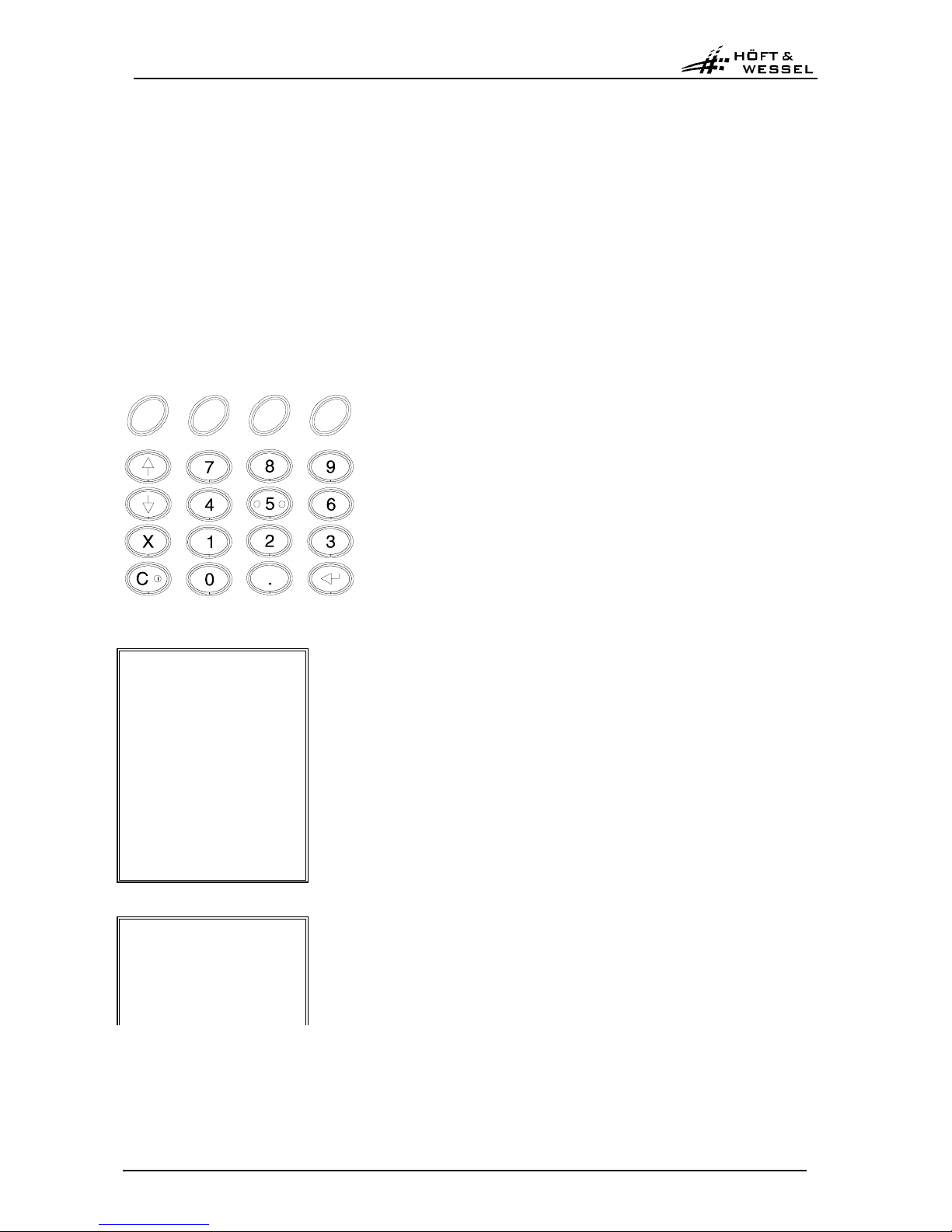
2.2 Keyboard functions
Key Function
Switch on/off device
Corrections (delete of last character)
Numerical keys for numerical inputs.
Decimal point inputs.
Scroll key downward.
Scroll key upward.
Close data input.
Function keys
Below the display you find – in addition to the key board further down – function keys. Those help in conjunction with relevant display messages to carry out program tasks faster.
Function keys below display, from left to right
Key Program part Function
F1
For operating system:*
For application program:**NoOptional assignment
F2
For operating system:*
For application program:**
End
Optional assignment
F3
For operating system:*
For application program:**
Delete
Optional assignment
F4
For operating system:*
For application program:**
Yes
Optional assignment
*Operating system: The operating system controls assignment and use of hardware resources, e.g. internal memory, processing
time, data carrier location and peripheral devices.
**Application program: The application program supports the user while processing certain tasks.
Page 12

Vectron User manual
© Höft & Wessel AG
Subject to amendment, errors excepted HW90195UserMan.doc 1.0 02.02.2001 Lin
page 12/70
2.2.1 Switch on/off HW 90196
Switch on/off HW 90196 with this key
C
I
.
After approx. 30 seconds HW 90196 switches off automatically (to sleep mode), if processor is not running operations, e.g. data transmissions. Any short key stroke will switch it back on. The program can be
continued from any point where it has been interrupted.
To switch off terminal press
for a while. If not pressed long enough second function will be activated.
The period of time before automatic switch off of HW 90196 kann be changed in the application program.
2.2.2 KEYBOARD-CLICK-function (keyboard beep) during standard mode
Any keyboard stroke will be answered by an acoustic beep signal.
If a key pushed in this program part is permitted you will hear a short soft beep for the keyboard click.
If a key pushed in this program part in not permitted you will hear a long loud beep as a warning signal.
Also a warning signal can be generated as acoustical support of messages and error warnings indicated
in the display.
Keyboard click and acoustic warning signals can be modified with the application program.
If charging voltage of accumulator drops below permitted values, no warning si gna l will be gener at ed.
Page 13

User manual Vectron
© Höft & Wessel AG
page 13/70
Lin 02.02.2001 1.00 HW90195UserMan.doc Subject to amendment, errors excepted
3. Technical data
3.1 Hardware
Casing:
Robust casing made of 100% reusable ABS-plastic, with integrated ring for
shoulder strap.
Dimensions:
L 156 mm, W 83 mm, H 35,5 mm.
Weight:
approx. 337 g (without accu block), less than 400 g (with accu block).
Strengthening:
Lateral grip edges.
Electronic pen for
touch function:
pen holder located top right on side of display
Processor:
Motorola MC 68328 „Dragonball“, 16,58 MHz.
Operating system:
HW-DOS.
Programming:
Choice of different languages (Assembler, High Level Languages C and C++,
...).
Memory:
Internal memory
1 MB S-RAM, can be apported into 512 kB TPA and 512 kB RAM-disk.
Flash:
1 MB, alternatively equipped with 2 MB.
Display:
Analog-resistive touch sensitive film.
Graphics type with 240 x 320 points , ¼ VGA Supertwist.
LED-background lighting.
Contrast adjustment via software.
Dimensions:
Module size 70,1 x 92,1 x 9,0 mm LxWxH.
Actual displayed size 60,6 x 79,8 mm.
Dot Size 0,225 x 0,225 mm.
Dot Distance 0,24 x 0,24 mm.
Keyboard:
Elastomer sheeting with 4 x 4 keys.
4 freely programmable function keys below display.
Backlighting (soft keys excluded).
Power supply:
Via separate NiCd-accu block HW 19196 (3,6 V).
Working time:
approx. 1000 re-charging cycles.
Data security:
Data safeguard of current program state (e.g. during change of accu pack) in
internal memory for 2 min. with gold-cap capacitor.
radio module:
HW 86020; integrated in casing.
Antenna
Wire antenna λ/4, omnidir ecti ona l, integrated in casing.
Frequency range
2.03 – 2.480 GHz
Communication
According to FCC part 15;
Uses frequency hopping;
Propritary protocol;
Radio data rate
24 kbps.
Range
In obstacle-free open areas upto 300 m, less in buildings,
depending on conditions.
Connections
Serial 3,3 V interface, incl. status lines.
Power supply
Via terminal unit.
Page 14

Vectron User manual
© Höft & Wessel AG
Subject to amendment, errors excepted HW90195UserMan.doc 1.0 02.02.2001 Lin
page 14/70
Read/Write unit for
smart cards:
• Plug-in reader in accordance with ISO 7816, FCI 7312 E 0225 S01, SMD
(at top of device).
• 2 plug-in places for 2 dealer cards in ID-000 format (under accu block).
Interfaces:
Infrared interface,Type S-IR, 115 kBit/s, to base station (lower edge);
Internal hidden12-pole contact pads
Temperature range:
Working temperature 0° to +40°C;
Storager temperature -20° to +60° C.
Humidity:
Up to 95 % (not condensing).
Auxiliary equipment:
Programmable acoustic beeper.
Reset key in accu casing.
3.2 Software
Power management:
For optimal use of power resources with automatic cutoff function, warning
indication in case off low charged accumulator and emergency stop trigger in
case of slow or abrupt fall of minimum power supply voltage.
Configuration possibilities:
Time to switch to sleep mode for electronical system and radio module.
Display lighting time, beepmode keyclick on/off, malfunction beep on/off.
Bootstrap loader:
BIOS via IR interface loadable .
Page 15
User manual Vectron
© Höft & Wessel AG
page 15/70
Lin 02.02.2001 1.00 HW90195UserMan.doc Subject to amendment, errors excepted
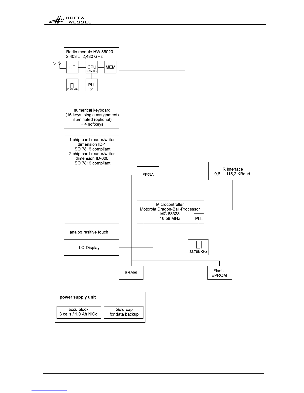
3.3 Block diagram
fig. 2: HW 90196, Block diagram
Page 16
Vectron User manual
© Höft & Wessel AG
Subject to amendment, errors excepted HW90195UserMan.doc 1.0 02.02.2001 Lin
page 16/70
3.4 Power consumption
Following table shows an approximate overview of power consumption of mobile terminal HW 90196 at
different operating states (BIOS terminal:‘09905, firmware radio module: #09907). The measured values
during operation depend on the current accumulator voltage. The measurement has been taken with an
accumulator voltage at 3,8 V while discharged accus provoke higher currents. The operating status of the
radio module has a significant influence of the overall power consumption of terminal HW 90196. In particular, if the terminal is switched off or outside radio frequency range (see No. 8, 12, 6, 4, 2), programming should meet these conditions, e.g. by switch off with bios_sleep() (see No. 13) after time out. Also, if
no optical warning can be indicated on switched off display of terminal (see No. 11 & 12) and radio connection is still running after a time out, the terminal should be completely switched off by bios_sleep()
(see No. 13).
No. CPU Displ.light Key light Radio module Display Power cons. in mA
1 on on on on/ conn. on 190
2 on on on on / no conn. on 225
3 on on off on / conn. on 135
4 on on off on / no conn. on 170
5 on off off on / conn. on 125
6 on off off on / no conn. on 160
7 doze off off on / conn. on 95
8 doze off off on / no conn. on 130
9 doze off off sleep / conn. on 50
10 doze off off sleep / no conn. on 130
11 doze off off sleep / conn. off 25
12 doze off off sleep / no conn. off 105
13
13 sleep off off off off 0,5
Page 17

User manual Vectron
© Höft & Wessel AG
page 17/70
Lin 02.02.2001 1.00 HW90195UserMan.doc Subject to amendment, errors excepted
4. Power supply of HW 90196 with accu block HW 19196
The power supply of HW 90196 is realised by an accu block which is inserted in the device.
The accu block HW 19196 consists of a module of 3 NiCd-cells with a total capacity of 1000 mAh.
The accu block HW 19196 has been specifically designed for use in the HW 90196. Contacting is realised
by two high-current contacts which are sunk in sockets to avoid unintentional short-circuits.
fig. 3: HW 19196, frontal view
4.1 Technical data
Type:
Separate ABS-plastic casing (Snap-In technique) with NiCd-accus;
3 cells, each 1,2 V.
Dimensions:
L approx.64 mm, W approx. 47 mm.
Weight:
Approx. 76 g.
Nominal capacity:
1.000 mAh
Working life:
approx. 1000 re-charging cycles.
Safety features:
Sunk-in contacts against short-circuits.
Contacts:
2 high-current contacts.
Optional 3
rd
contact for charging condition monitoring via HW 90196.
Spring mounted design in plastic inset, self-centering form
High-current contacts
Page 18
Vectron User manual
© Höft & Wessel AG
Subject to amendment, errors excepted HW90195UserMan.doc 1.0 02.02.2001 Lin
page 18/70
4.2 Charging condition of accu block
The loading capacity of accu block should always be used to full extend. Keep HW 90196 in operation
until the message „attention! Recharge batteries!!!“ is indicated in the display. After this the device can
still be used for a while, however only essential inputs should be entered and the accu block be recharged afterwards.
If the accumulator voltage drops below a permitted value, the device switches off automatically. After
switch on display indicates „emergency cutout! check accu!!!“.
Accu block can be recharged in accu charging unit HW 16196 (see sec. Fehler! Verweisquelle konnte
nicht gefunden werden.) or in communication station HW 50196.
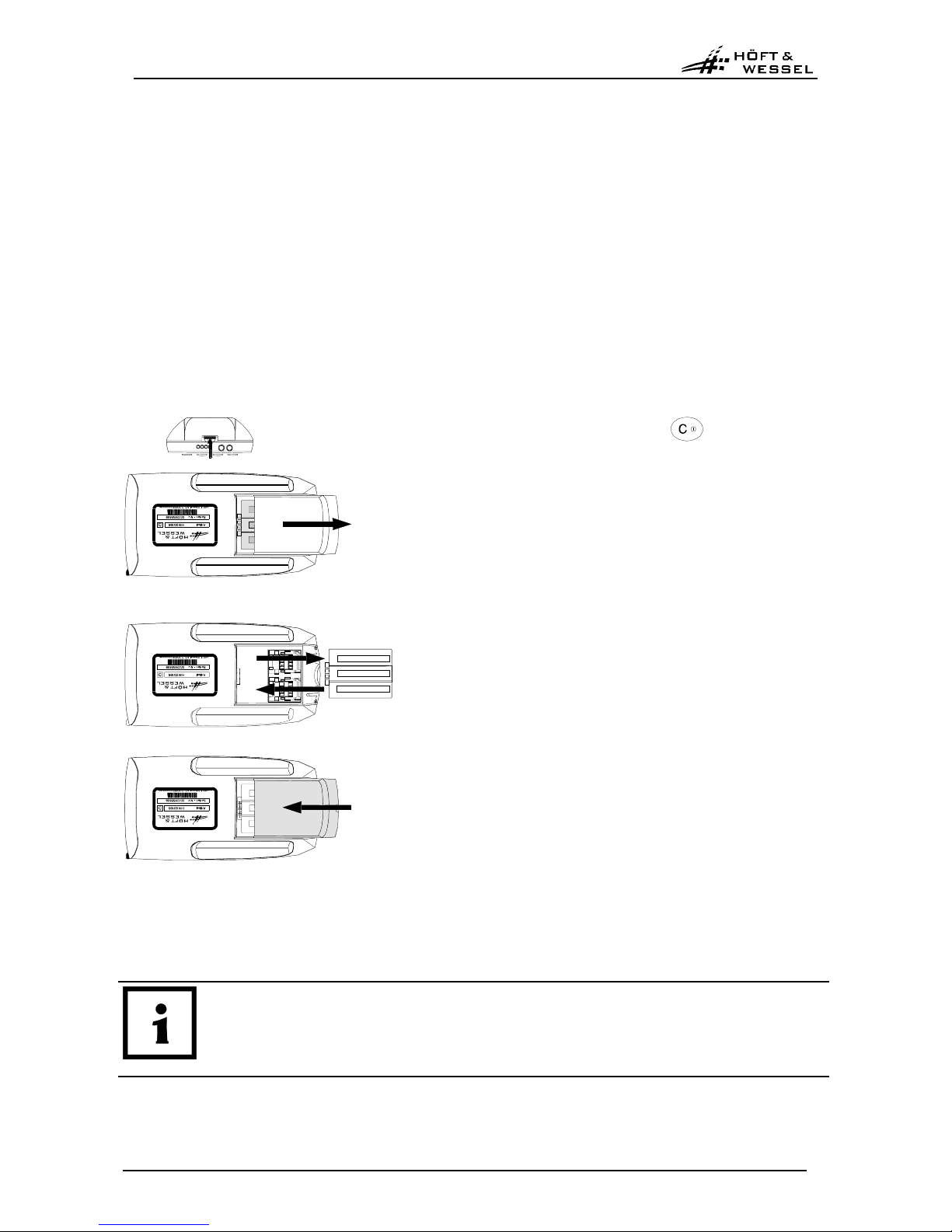
4.3 Replacing the accu block in HW 90196
Following steps are required to change the accu block in HW 90196:
1. Switch off HW 90196 with key and turn device on rear side.
2. Push locking button of accu casing towards top and
remove lid of accu casing.
3. Remove accu block.
4. Insert new accu block (reverse battery protection-no
vice versa insertion poss ib le),
5. Replace accu casing lid and close.
fig. 4: Replacin accu block of HW 90196
General: It is not recommended to pull out accu block while HW 90196 is still switched on. Operating
states that lead to a system crash after restart of the device might appear.
IMPORTANT!
Swich off device before taking out accu block!
Taking out the accu block during an accounting operation with the customers smart
card inserted might destroy the smart card!
Page 19
User manual Vectron
© Höft & Wessel AG
page 19/70
Lin 02.02.2001 1.00 HW90195UserMan.doc Subject to amendment, errors excepted
4.4 Maintenance of accu block
If accu blocks are stored, they should be re-charged on a regular basis. After a period of 6-8 weeks, even
a new accu block is discharged to such an extent due to self-discharge that it is no longer possible to
operate a HW 90196 with it.
About how to store device and accu block see also 1.1 „Important comments for application“.
IMPORTANT!
A stored MDE which is not used, has to be recharged once per month.
The maintenance and service of such accus which have not been used for a longer period may
be executed by the Höft & Wessels service department. For further information, please contact
our service line : Tel. (0049) 01803/ 23 28 29
As for maintenance of the accu block, the following points should be taken into account:
Good:
• Daily use of the accu block
• Total use of capacity (discharge) until display shows "attention! - recharge batteries!!!"
• Re-charging with charging unit HW 16196 or communication station HW 50196
Bad:
• Occasional use of accu block
• Heat impact (increased self-discharging)
• Frost impact
Very bad:
• Total discharging
• Humidity; aggressive gaseous substances, which increase corrosion of contacts
• Storage with temperatures lower than -20°C
• Charging with temperatures lower than 0°C
4.5 Disposal of used accus
"NiCd-accu cells contain between 15 and 20 % highly toxic cadmium."
(Source: test 12/88 p. 1175)
Used accu cells must under no circumstances be disposed with common household waste, as the con-
tained cadmium will result in heavy pollution of environment.
All used accu cells have to be disposed of in an appropriate way. For this purpose, they have to be re-
turned to Höft & Wessels. As a part of its normal service, Höft & Wessels guarantees that all used accu
cells are fed to the recycling process.
The return of the accu cells ensures 100% reuse of the chemicals contained. This recycling process
avoids any impact to the environment.
See also extract from BattV - 01.10.1998:
"The manufacturers are obliged to take back and reuse toxic containing batteries according to the regulations and dispose of non-reusable batteries that have been handed in by distributors (§5) or public disposal departments (§9).“
Page 20
Vectron User manual
© Höft & Wessel AG
Subject to amendment, errors excepted HW90195UserMan.doc 1.0 02.02.2001 Lin
page 20/70
5. Operating system
Preface
Those functions which are explained in this chapter are installed as standard features in the operating
system of the HW 90196 and are independent of the type of application program. The user will usually not
have to deal with the operating system, as during normal operation only the displays of the application
program are presented. These are explained in detail in the corresponding documentation of the application program.
For special purposes it may however be useful that the responsible support person of the HW 90196 uses
the functions of the operating system explained in the following. Note that by means of the functions given
below, individual data as well as complete programs may be deleted!
Function key layout for operating system level:
Function keys
F1 F2 F3 F4
Funktion:
F1 F2 F3 F4
NO END DELETE YES
- HW 90196 -
12345678901234567890
The font used in the operating system presents text in the graphics display
in 20 lines with 20 characters each.
Graphics type with 240 x 320 points.
- HW 90196 -
The messages of the operating system do not use the complete space of
20 lines. Therefore, in the following, the displays are represented without
lower frame, in order to emphasise that the display presentation is actually
bigger in reality.
Page 21
User manual Vectron
© Höft & Wessel AG
page 21/70
Lin 02.02.2001 1.00 HW90195UserMan.doc Subject to amendment, errors excepted
5.1 Operating system-basic menu
300
- HW 90196 - 8 320 (system-Info)
9 326 (checking RAM-/FLASH-Disk)
327 (checking RAM-/FLASH-Disk)
↙
↙↙
↙ (Entry) 305 (if no application programm is existing)
310 (if program is already existing)
0 302 (choose language)
additional inputs:
6 0 12 0 52 (format Flash-Disk, see 5.4)
3 0 1 4 1 5 9 0 (auxiliary program for user, e.g. setting of accu charging condition,
radio module configuration and -update, ...)
After having pressed the 9-key, the system starts to check its disks. If no errors are detected on the disks,
the device executes a warm-start. By pressing the C-key, the basic menu of the operating system is
called again.
326
- HW 90196 -
Checkdisk B: OK
File system B: OK
WBoot -> C
C 300 (Operating system-basic menu)
The HW 90196 presents the following display, if an error has been detected on one of its disks:
327
- HW 90196 -
Checkdisk B: Error
F-CBoot ! -> C
The application program has to be deleted in order to avoid non-defined program conditions and has to
be downloaded again in order to take the HW 90196 back into operation.
Page 22

Vectron User manual
© Höft & Wessel AG
Subject to amendment, errors excepted HW90195UserMan.doc 1.0 02.02.2001 Lin
page 22/70
302
Select Language
1=D 2=GB
↙
↙↙
↙ (Entry) or F2 (End)
300
1 300 (German language chosen)
2 300 (English language chosen)
With language selected „2=GB“ system messages will be presented in english. English will be set as a
standard settting after a reset. The language set by the user remains after a warm start. This is also the
case after an update with a german language BIOS version as the preset language remains until further
reset or change through the current user.
305
load program ?
No Yes
Is only presented, if no application program has been downloaded
F4 (Yes) 400 (PC-connection via infrared syst. interface)
F1 (No) 315
310
start program ?
No Yes
Is only presented, if an application program has been downloaded
F4 (Yes) Start of application program
F1 (No) 305
315
Fildtransfer
from PDE ?
No Yes
F4 (Yes) MDE MDE-connection
F1 (No) 300
Page 23

User manual Vectron
© Höft & Wessel AG
page 23/70
Lin 02.02.2001 1.00 HW90195UserMan.doc Subject to amendment, errors excepted
5.1.1 System-info-display
320
SSSSSSSS----NNNNNNNN
EEEE-XXXX-YYYY-VV.VV
FLASH:nn RRRR DDDD
BOOTLDR: BBBBB
TT.MM.JJ HH:MM
8 300 (back to system menu)
SSSSSSSS
= Customer-specific start set
NNNNNNNN
= Serial number of the HW 90196 (identical with number indicated on type plate)
EEEE
= Customer-specific EPROM-No. (Höft & Wessel internal).
XXXX
= Size of working storage (hex).
YYYY
= Storage capacity of RAM-Disk (hex).
VV.VV
= Version-No. of the operating system
nn
= Number of Flash-Chips.
RRRR
= Storage capacity (Flash) (hex) for the system
DDDD
= Storage capacity of Flash-Disk (hex).
BBBBB
= Customer-specific Bootloader-No. (Höft & Wessel internal).
TT.MM.JJJJ HH:MM
= Date/time on system watch
If the MDE is inserted in the communication station HW 50196, system-info-display (320) is followed by a
presentation of the EPROM-No. of the communication station.
321
KOM-Station
H&W EPROMNR=XXXXX
TT.MM.JJJJ
Page 24

Vectron User manual
© Höft & Wessel AG
Subject to amendment, errors excepted HW90195UserMan.doc 1.0 02.02.2001 Lin
page 24/70
5.2 Warm start
A warm start is the complete initialization of hard- and software.
After a warm start (message: Ws!->C) an application program will be started automatically, if an
autostart file with any name and the extension „AST“ has been generated beforehand on the disk. This
automatic restart process can be supressed by not activating „C“ but the „F1“-key followed by keys
„2071828“. After this, the functions of the operating system-basic menu can be used.
450
WBoot ! -> C
C 300 (System menu)
or Start of application program (if an autostart
file has been generated beforehand)
F1, “2.71828“ 300 Suppress autostar t
5.3 Reset
A reset means the most profound level to process an initialization of hard- and software. The reset provokes an abandonment of the running application programm at any given position. To proceed, the reset-key in the accumulator compartment may be activated. Note that the accumulator block should only
be removed if the HW 90196 is switched off, as otherwise files could be damaged during running write
operations.
If an application program is stored on the Flash-Disk, it will be started automatically after a reset with the
stored file and extension „AST“ without needing further instructions of user. The automatic start of the
application program after reset can be suppressed by activating a combination of keys as followed: press
at same time: „F1+F4+0“. Only in this case the operating system will check the Flash-Disk.
The following message „Ws! -> C“ must not be confirmed with the ‚C‘-key as otherwise the application
program will be automatically started (see chap. above 5.2).
In order to initiate a reset, proceed as follows:
1. Take out the accu block (with switched off HW 90196).
2. Press the reset-key which is located under the accu block and above the sticker (see also
fig 17, p. 52).
Do press the reset-key carefully, with low expenditure of force. You may want to use a bend up
paper clip, e.g..
3. Insert the accu block. The HW 90196 is automatically switched on again.
Page 25

User manual Vectron
© Höft & Wessel AG
page 25/70
Lin 02.02.2001 1.00 HW90195UserMan.doc Subj ect to amendment, errors excepted
5.4 Format FLASH-Disk
Note!
The procedures described in this chapter will delete all data and programs on the HW
90196 and should thus be executed only in emergency cases!
The FLASH-disk in the HW 90196 is administered as a virtual hard disk. In order to delete all files on a
disk, it has to be formated anew just as a floppy or a HD.
The process starts with the following display:
300
- HW 90196 - For a correctly entered code 375
(do not press the enter-key)
The following code has to be entered:
" 6 0 12 0 52 "
The procedure may be repeated starting from display 300, if necessary.
375
format flashdisk? For a correctly entered code 380
any key 300 system menu
The following code has to be entered:
" 3 0 1 4 1 5 9 0 "
Any other key will cancel the process while the system goes back to menu 300.
380
formatting
disk B:
automatically
385
The progress of the action is indicated by a rotating bar (*).
Page 26

Vectron User manual
© Höft & Wessel AG
Subject to amendment, errors excepted HW90195UserMan.doc 1.0 02.02.2001 Lin
page 26/70
385
formatting
completed -> C
C 300 system menu
After confirmation with the C-key in display 385 the FLASH-disk has been formatted succesfully.
5.5 Radio module configuration menu (DECT-menu)
5.5.1 Terminal
- HW 90196 - Enter the code "30141590" from the basic state of the operating system.
->DECT menu
Printer menu
END
Select „DECT-menu“ with arrow keys.
Enter (↵) for confirmation.
->DECT serial no.
Offline Sub. SK
Oflline Sub SMK
Air Subscription
Defaults
Firmware
Download
END
Menu levels of DECT -menu
Select with arrow keys and enter (↵) for confirmation.
5.5.2 Functions
All avaible functions, their expressions, display indications and commands that will be transmitted to the
radio module within the configuration mode, will be explained in the following. These functions are also
selected by the enter- and arrow-keys. Due to the changed format of the commands all functions are
classified as new and old firmware. The radio module firmware version will be determinded before transmission of a command.
These functions prove to be advantageous as they enable a configuration of the radiio module without
having loaded an application program beforehand and thus an application program can later be duplicated onto the Flash-disk via radio connection. Even in the case of an unintentional delete of the application program at the customers place, the terminal does not need to be sent to the service department.
Page 27

User manual Vectron
© Höft & Wessel AG
page 27/70
Lin 02.02.2001 1.00 HW90195UserMan.doc Subj ect to amendment, errors excepted
Radion module serial number
Determination and indication of radio module no. of PT-radio-modules.
Sent commands Display Possible error message Remarks
GNDNR N-number: <NO> radio module does not respond
End with any key
Offline-Subscribtion SK
Proceeds offline-subscribing, requires entering of radio module no., PIN and PAK of radio terminal
Sent commands Display Possible error messages Remarks
Enter N-number of
remote station:
Stop with F2-key, delete
with C-key
Enter PIN: Stop with F2-key, delete
with C-key
Enter PAK: Stop with F2-key, delete
with C-key
DISUB ALL
SISUB322, <NO>,
<PIN>, <PAK>
Subscription executed Subscription failed
End with any key
Offline-Subscription with SubscriptionMasterKey / SMK:
Proceeds offline-subcription, requires entering of radio module no., PIN and SMK of FT.
Sent commands Display Possible error messages Remarks
Enter radio module
serial number of remote station:
Stop with F2-key, delete
with C-key
Enter PIN: Stop with F2-key, delete
with C-key
Enter SMK: Stop with F2-key, delete
with C-key
DISUB ALL
SISUM322, <NO>,
<PIN>, <SMK>
Subscription executed Subscription failed
End with any key
On-Air-Subscription:
Logs PT on FT, requires entering of PARK and PIN, entries can be deleted with F2-key, FT must be in
online-subscription mode.
Sent commands Display Possible error messages Remarks
Enter PARK: Stop with F2-key, delete
with C-key
Enter PIN: Stop with F2-key, delete
with C-key
DISUB ALL
SISUA <PARK>,
<PIN>
Subscription executed Subscription failed
End with any key
Page 28

Vectron User manual
© Höft & Wessel AG
Subject to amendment, errors excepted HW90195UserMan.doc 1.0 02.02.2001 Lin
page 28/70
Standard settings
Resets radio module to standard settings.
Sent commands Display Possible error messages Remarks
SPBD115200
SPTM PT
SPPR OFF
SPCTR OFF
SPCCN 1
SPINI 0 Setting of standard
settings successful!
Setting of standard settings
failed!
Firmware:
Displays of radio module firmware. The user test menu contains DECT in a submenu with the function
„firmware“ and a notice about the version number and the manufacturer date of the radio module firmware.
Download:
Download of the radio modules with new firmware, the files root.pp and root.bin have to be generated on
the Flash-disk beforehand.
This function does not refer to the mobile printer HW 90195.
5.5.3 Printer
- HW 90196 - Enter the code "30141590" from the basic state of the operating system.
DECT menu
->Printer menu
END
Select „Printer menu“ with arrrow keys.
Enter (↵) for confirmation.
->DECT serial no
Offline Sub. SK
Oflline Sub SMK
Air Subscription
Defaults
Firmware
END
Menu levels DECT-menu Printer
Select with arrow keys and enter (↵) for confirmation.
The DECT-menu for the printer is, concerning its functions, equal to the
one for the HW 90196. The DECT-menu for the terminal additionally contains the menu level „download“.
To configure the radio module in the printer the terminal and the printer have to be aligned with their infrared interfaces on the bottom sides of the devices towards each other. The printer must be in IR mode
(see also chapt. 6.6). Stray light influences, e.g. by fluorescent lamps, should be avoided, if possible.
Page 29

User manual Vectron
© Höft & Wessel AG
page 29/70
Lin 02.02.2001 1.00 HW90195UserMan.doc Subj ect to amendment, errors excepted
5.6 Connection to a PC
The HW 90196 is able to communicate with a PC via the infrared-system interface or the integrated radio
module.
A communcation station HW 50196 is employed for communication via the infrared-system interface. It
can be connected directly with a PC (H&W-cable 63) or contact can be established via a modem connection. The modem can alternatively to cable 63 be connected to the communication station.
The connection between HW 90196 and PC (display 400) is established starting from the operating system (display 304, „load program“?).
400
load program
via modem ?
No Yes
F4 (Yes) 405
F1 (No) 420
If the connection has once been established, it is possible to send or recieve data. This process is monitored and controlled by the PC.The HW 90196 operates in the server mode, i.e. it reacts only to commands of the PC and the F2 (End)-key.
The connection to the PC is only terminated by a command of the PC, by pressing the F2(End)-key on
the HW 90196 or because of a time-out, if it was not possible to establish the connection or if the connection hab been interrupted.
405
Phone-Nr./Receiver: ↙↙↙↙ (Entry) 410 (Blank entry; MDE switches to call-off
mode)
F2 (End) 300 (system menu)
Entry of a phone number terminated by
↙
↙↙
↙ (Entry) 410 (call MDE)
410
dial up... F2 (End) 450 (Warm start)
after 60 s time-out 450 ( - “ -)
Connect established 415
415
PC-connection
PDE is waiting
F2 (End)
or controlled by the PC 450
Cancel by time-out 450
Page 30

Vectron User manual
© Höft & Wessel AG
Subject to amendment, errors excepted HW90195UserMan.doc 1.0 02.02.2001 Lin
page 30/70
The display 415 is only presented, if the HW 90196 has been inserted in the communication station. Else
the communication program is aborted.
420
load program
from PC via IrDA ?
No Yes
F1 (No) 425
F4 (Yes) 415
425
load program
from PC via DECT ?
No Yes
F1 (No) 315 ( p. 22)
F4 (Yes) 415
450
WBoot ! -> C
C 300 (system menu)
or Start of the application program (if an autostart-
file is existing.)
A warm start is executed on the HW 90196 after having terminated the connection. By pressing the C-key
the operating system opens up again. The application program is automatically started up again, if an
auto-start file and an application program is existing.
If the connection to the PC has been established manually starting from the operating system (display
300), it is necessary to confirm display 415 by pressing the C-key.
Cancel the connection
The HW 90196 executes a warm start (display 450), if the communication has been interrupted by
pressing the F2 (End)-key.
Page 31

User manual Vectron
© Höft & Wessel AG
page 31/70
Lin 02.02.2001 1.00 HW90195UserMan.doc Subj ect to amendment, errors excepted
5.7 Error messages of the operating system
Major messages of the operating system, which are given out as a result of exceptional situations, may
only be deleted by pressing the C-key. Thus, these messages contain the additional information:
"-> C"
All other messages, which are presented in the display, may be deleted by pressing any key. It is how-
ever recommended to write down the presented message in order to be able to inform the Höft&Wessel
service line. These data may faciliate trouble-shooting and error elimination tremendously.
Power supply
500
Empty display, device has been switched off.
The device has to be switched on by pressing the
-key. If the display is still not presented, then the
voltage of the accu is lower than necessary for operating the device. Switch off HW 90196 and change
the accu block or insert HW 90196 in the communication station or in the accu charging station 16196.
If the HW 90196 still does not react, the error may have different causes. These have to be detected by
the Höft&Wessel-service. For this reason, the device has to be sent to Höft&Wessel.
505
Attention !
recharge
batteries !!!
The chargemeter detected a too low accu voltage. The voltage of the accu is checked with every key
stroke. If a certain value is exceeded, this message is given out for app. 2 seconds.
It is recommended to insert a re-charged accu block immediately or to insert the HW 90196 in the communication station HW 50196 or in the accu charging station HW 16196.
It is however possible to suppress this message by the application program.
515
emergency cutout!
check accu !!!
The message in display 515 is presented for several seconds after a forced switch-off, initiated by a too
far discharged accu block.
It is however possible to suppress this message by the application program.
Page 32

Vectron User manual
© Höft & Wessel AG
Subject to amendment, errors excepted HW90195UserMan.doc 1.0 02.02.2001 Lin
page 32/70
6. Printer HW 90195
The mobile printer HW 90195 has been specifically designed for use with POS terminal HW 90196. The
connection to the terminal is established via radio transmission. The printer is powered by an individual
high-performance power supply. Also a belt fastening facility is provided. The Easy Paper Load Technology for fast changing of the paper reel has been applied.
fig. 5: HW 90195, frontal view
Locking of accu
casing lid
(both sides)
Infrared
interface
On/Off key
LED
(red-green)
Un-lock button for paper casing fla
p
Paper reel cas.
Magnetic card
reader
(p
ull-thr.
)
Page 33

User manual Vectron
© Höft & Wessel AG
page 33/70
Lin 02.02.2001 1.00 HW90195UserMan.doc Subj ect to amendment, errors excepted
6.1 Technical data
6.1.1 Hardware
Casing:
Robust ABS-plastic casing with fastening facilities for belt
Dimensions:
L 133 mm, W 98 mm, H 64 mm.
Weight:
Ca. 446 g incl. rechargable battery, ca. 280 g without battery.
On/Off switch:
Key design.
Printing unit:
High-speed thermal printer ,
fixed thermal head,
Easy Paper Load Technology,
Loosening of fricitional drum with lever mechanism.
Printing speed:
Up to 27 mm/s.
Width of paper:
58 mm +0 / -1 mm.
Actual width of print:
48 mm.
Paper cutting:
Stainless blade with saw tooth.
Paper control:
Detects end of paper.
Optical indication:
1 red LED and 1 green LED on operational frontside.
Power supply:
With NiCd battery block HW 19195
Separate battery block with 5 x 1,2 V cells, 1100 mAh each
Working time:
At full operation: ca. 8 h. Switch off after operation.
Interface IR:
1 infrared interface, 56,7 kBit/s (top side).
Radio module:
HW 86020 , integrated in casing.
Antenna
Wire antenna λ/4, omnidir ecti ona l, integrated in casing.
Frequency
range
2.03 – 2.480 GHz
Communication
According to FCC part 15;
Uses frequency hopping;
Propritary protocol;
Radio data rate
24 kbps.
Range
In obstacle-free open areas upto 300 m, less in buildings,
depending on conditions.
Connections
Serial 3,3 V interface, incl. status lines.
Power supply
Via terminal unit.
Magnetic card reader:
Integrated in casing.
3 tracks readable, according to ISO 7811.
Type: American Magnetics Type 45D, TRK3, art.no. T17645.
Read data of magnetic card are transmitted to terminal via radio transmis-
sion.
Standard paper reel:
30 mm outer diameter.
9 m Length at paper weight < 60 g / m².
Paper type:
TF50KS-E2C 65 µm (Nippon Paper Industries)
TP50KJ-R 65 µm
AP50KS-E 65 µm
HP220-AB1 65 µm (Mitsubishi Paper)
PD160R-N 75 µm (Oji Paper)
Page 34

Vectron User manual
© Höft & Wessel AG
Subject to amendment, errors excepted HW90195UserMan.doc 1.0 02.02.2001 Lin
page 34/70
6.1.2 Software
Instruction set:
Epson Escape-sequencies for POS-printer (subset).
Character set:
Line print, any font type, special characters printable.
Automatic line break after 24 characters/line at standard font.
Infrared:
IR-protocol, Initialization of radio module via IR-interface.
Radio module features:
Sleep-mode programmable;
Sleep-mode indication via LED;
Akku-low indication via LED.
Page 35

User manual Vectron
© Höft & Wessel AG
page 35/70
Lin 02.02.2001 1.00 HW90195UserMan.doc Subj ect to amendment, errors excepted
6.1.3 Block diagram
fig. 6: Drucker HW 90196, Block diagram
Page 36

Vectron User manual
© Höft & Wessel AG
Subject to amendment, errors excepted HW90195UserMan.doc 1.0 02.02.2001 Lin
page 36/70
6.1.4 Power consumption
Following table shows an approximate overview of power consumption of mobile printer HW 90195 at
different operating states (BIOS printer #09906, firmware radio module: #09907). The power consumption
during printing depends much on the print image. The pulse motor will be supplied with power for 15 seconds after each printout (see 2), holding the printout tight for easy tear off. During this period of time the
mobile printer can turn to operating state 5 as a result of a canceled radio connection. If the mobile terminal is switched off or out of radio range, the power consumption will be significantly increased (see 6&4).
No. CPU Radio module Stepping motor Print line Power consumption in mA
1 on on / conn. Paper forward feed on 500 ... 3000
2 on on / conn. Holding paper off 300
3 on on / conn. off off 110
4 on on / no conn. off off 150
5 doze sleep / conn . of f off 20
6 doze sleep / no conn. off off 100
7 off off off off 0,3
6.2 Functions
6.2.1 Operating modes
On
The green LED of the printer is switched on or flashing (depending on charging condition of accu). Printer can be switched off with on/off-key.
Off
All LEDs of the printer are switched off. Printer can be switched on with on/off-key.
Printer turns to sleep mode immediately after switch on.
Sleep mode
The printer turns immediately after switch on from off-mode, resp. after a period of 30
seconds with no radio connection, to sleep mode (green LED flashes every 2 seconds).
The printer can be activated with the on/off-key or via radio by the Base Station. Now
the printer is switched on. To activate the printer via radio a signal will be sent to the
printer to establish a connection. If the printer turns to the sleep mode because of the
30s-time-out function, the connection will still remain for further activation processing.
Note!
The printer should always be switched off after operation (do not let the printer remain at
sleep mode).
If the printer will not be used for a long period of time ( > 1 day) , take out accu block.
Page 37

User manual Vectron
© Höft & Wessel AG
page 37/70
Lin 02.02.2001 1.00 HW90195UserMan.doc Subject to amendment, errors excepted
6.2.2 Function indication LEDs
A list of all LED-combinations will be shown in the following.
The green LED usually indicates the accu charging condition:
• on = „ok“,
• flashing = „low“ oder „discharged“.
The red LED indicates several error conditions:
• off = „ok“,
• on = „no paper“ resp. „open casing flap“,
• flashing = „no radio connection“.
Additionally, the green LED flashes every 2 seconds, if the printer is at sleep mode. Update processes
and the inital switch on from „off-mode“ are the exceptions.
Printer mode accu charg-
ing cond.
Status paper/
casing flap
Status radio
connection
green LED red LED
OFF - - - aus off
SLEEP - - - flash (ca. 0,5Hz) off
ON ok ok ok on off
ON ok Error - on on
ON ok ok Error on flash (ca. 2Hz)
ON low / discharg. ok ok flash (ca. 2Hz) off
ON low / discharg. Error - flash (ca. 2Hz) on
ON low / discharg. ok Error flash (ca. 2Hz) flash (ca. 2Hz)
Update / transmission
- - ok flash (ca. 0,5Hz
at block size of
1kByte)
off
Update / programming
- - ok off on
Tab. 1: optical indication of printer mode
6.2.3 Acoustic signals
The printer generates acoustic signals during certain operations.
Operation acoustic signal
Switch on of printer with on/off-key. Double whistle sound.
Printer turns to sleep mode. Whistle sound after app. 5 s (radio connection has
been interrupted).
radio connection is interrupted. Whistle sound as error indication.
Printer recieved command to read magnetic
card.
Beep sound as request to pull magnetic card through
slot of reading unit.
Magnetic card has been pulled through slot of
reader unit.
Beep sound after having pulled a magnetic card
through slot of reader unit.
Page 38

Vectron User manual
© Höft & Wessel AG
Subject to amendment, errors excepted HW90195UserMan.doc 1.0 02.02.2001 Lin
page 38/70
6.3 Fonts
6.3.1 Standard font 1
Following table shows an overview of provided font 1 of mobile printer .
HEX Dez. ASCII HEX Dez. ASCII HEX Dez. ASCII HEX Dez. ASCII
000 2032SP 4064
@
60 96
`
01 1 21 33
!
41 65
A
61 97
a
02 2 22 34
“
42 66
B
62 98
b
03 3 23 35
#
43 67
C
63 99
c
04 4 24 36
$
44 68
D
64 100
d
05 5 25 37
%
45 69
E
65 101
e
06 6 26 38
&
46 70
F
66 102
f
07 7 27 39
′′′′
47 71
G
67 103
g
08 8 28 40
(
48 72
H
68 104
h
09 9 HT 29 41
)
49 73
I
69 105
i
0A 10 LF 2A 42
*
4A 74
J
6A 106
j
0B 11 2B 43
+
4B 75
K
6B 107
k
0C 12 2C 44
,
4C 76
L
6C 108
l
0D 13 CR 2D 45
-
4D 77
M
6D 109
m
0E 14 2E 46
.
4E 78
N
6E 110
n
0F 15 2F 47
/
4F 79
O
6F 111
o
10 16 DLE 30 48
0
50 80
P
70 112
p
11 17 DC1 31 49
1
51 81
Q
71 113
q
12 18 DC2 32 50
2
52 82
R
72 114
r
13 19 33 51
3
53 83
S
73 115
s
14 20 34 52
4
54 84
T
74 116
t
15 21 35 53
5
55 85
U
75 117
u
16 22 36 54
6
56 86
V
76 118
v
17 23 37 55
7
57 87
W
77 119
w
18 24 38 56
8
58 88
X
78 120
x
19 25 39 57
9
59 89
Y
79 121
y
1A 26 3A 58
:
5A 90
Z
7A 122
z
1B 27 ESC 3B 59
;
5B 91
[
7B 123
{
1C 28 3C 60
<
5C 92
\
7C 124
1D 29 GS 3D 61
=
5D 93
]
7D 125
}
1E 30 3E 62
>
5E 94
^
7E 126
∼∼∼∼
1F 31 3F 63
?
5F 95
_
7F 127
Page 39

User manual Vectron
© Höft & Wessel AG
page 39/70
Lin 02.02.2001 1.00 HW90195UserMan.doc Subject to amendment, errors excepted
HEX Dez. ASCII HEX Dez. ASCII HEX Dez. ASCII HEX Dez. ASCII
80 128 A0 160 C0 192 E0 224
81 129 A1 161 C1 193
’
E1 225
82 130 A2 162 C2 194
___
E2 226
83 131 A3 163
£
C3 195
^
E3 227
84 132 A4 164
¤
C4 196
Ä
E4 228
85 133 A5 165
¥¥¥¥
C5 197
Å
E5 229
å
86 134 A6 166 C6 198
Æ
E6 230
æ
87 135 A7 167
§
C7 199 E7 231
88 136 A8 168
”
C8 200 E8 232
89 137 A9 169
’
C9 201 E9 233
8A 138 AA 170
”
CA 202
(SP)
EA 234
8B 139 AB 171 CB 203
,
EB 235
8C 140 AC 172 CC 204 EC 236
8D 141 AD 173 CD 205 ED 237
8E 142 AE 174 CE 206
IJ
EE 238
8F 143 AF 175 CF 207
ij
EF 239
90 144 B0 176 D0 208 F0 240
91 145 B1 177 D1 209
Ň
F1 241
92 146 B2 178
†
D2 210
|
F2 242
93 147 B3 179 D3 211
█
F3 243
94 148 B4 180
’
D4 212
_
F4 244
95 149 B5 181
m
D5 213 F5 245
96 150 B6 182 D6 214
Ö
F6 246
97 151 B7 183
.
D7 215 F7 247
98 152 B8 184 D8 216
Ø
F8 248
ø
99 153 B9 185 D9 217 F9 249
9A 154 BA 186
”
DA 218 FA 250
9B 155 BB 187 DB 219 FB 251
9C 156 BC 188 DC 220
Ü
FC 252
9D 157 BD 189 DD 221 FD 253
9E 158 BE 190 DE 222 FE 254
9F 159 BF 191 DF 223
ß
FF 255
Page 40

Vectron User manual
© Höft & Wessel AG
Subject to amendment, errors excepted HW90195UserMan.doc 1.0 02.02.2001 Lin
page 40/70
6.3.2 Standard font 2
Following table shows an overview of font 2 of mobile printer.
HEX Dez. ASCII HEX Dez. ASCII HEX Dez. ASCII HEX Dez. ASCII
000 2032SP 4064
@
60 96
`
01 1 21 33
!
41 65
A
61 97
a
02 2 22 34
u
42 66
B
62 98
b
03 3 23 35
#
43 67
C
63 99
c
04 4 24 36
$
44 68
D
64 100
d
05 5 25 37
%
45 69
E
65 101
e
06 6 26 38
&
46 70
F
66 102
f
077 2739 4771
G
67 103
g
08 8 28 40
(
48 72
H
68 104
h
09 9 HT 29 41
)
49 73
I
69 105
i
0A 10 LF 2A 42
*
4A 74
J
6A 106
j
0B 11 2B 43
+
4B 75
K
6B 107
k
0C 12 2C 44
,
4C 76
L
6C 108
l
0D 13 CR 2D 45
-
4D 77
M
6D 109
m
0E 14 2E 46
.
4E 78
N
6E 110
n
0F 15 2F 47
/
4F 79
O
6F 111
o
10 16 DLE 30 48
0
50 80
P
70 112
p
11 17 DC1 31 49
1
51 81
Q
71 113
q
12 18 DC2 32 50
2
52 82
R
72 114
r
13 19 33 51
3
53 83
S
73 115
s
14 20 34 52
4
54 84
T
74 116
t
15 21 35 53
5
55 85
U
75 117
u
16 22 36 54
6
56 86
V
76 118
v
17 23 37 55
7
57 87
W
77 119
w
18 24 38 56
8
58 88
X
78 120
x
19 25 39 57
9
59 89
Y
79 121
y
1A 26 3A 58
:
5A 90
Z
7A 122
z
1B 27 ESC 3B 59
;
5B 91
[
7B 123
{
1C 28 3C 60
<
5C 92
\
7C 124
1D 29 GS 3D 61
=
5D 93
]
7D 125
}
1E 30 3E 62
>
5E 94
^
7E 126
∼∼∼∼
1F 31 3F 63
?
5F 95
_
7F 127
Page 41

User manual Vectron
© Höft & Wessel AG
page 41/70
Lin 02.02.2001 1.00 HW90195UserMan.doc Subject to amendment, errors excepted
HEX Dez. ASCII HEX Dez. ASCII HEX Dez. ASCII HEX Dez. ASCII
80 128 A0 160 C0 192
À
E0 224
à
81 129 A1 161
i
C1 193
Á
E1 225
á
82 130 A2 162
¢
C2 194
Â
E2 226
â
83 131 A3 163
£
C3 195
Ã
E3 227
ã
84 132
„
A4 164
¤
C4 196
Ä
E4 228
ä
85 133
...
A5 165 C5 197
Å
E5 229
å
86 134
†
A6 166 C6 198
Æ
E6 230
æ
87 135
ŧ
A7 167
§
C7 199
Ç
E7 231
ç
88 136
^
A8 168
¨
C8 200
È
E8 232
è
89 137
‰
A9 169
©
C9 201
É
E9 233
é
8A 138 AA 170 CA 202
Ê
EA 234
ê
8B 139 AB 171
«
CB 203
Ë
EB 235
ë
8C 140
€
AC 172
¬
CC 204
Ì
EC 236
ì
8D 141 AD 173
-
CD 205
Í
ED 237
í
8E 142 AE 174
®
CE 206
Î
EE 238
î
8F 143 AF 175
¯
CF 207
Ï
EF 239
ï
90 144 B0 176
°
D0 208 F0 240
91 145
`
B1 177
±
D1 209
Ñ
F1 241
ñ
92 146
'
B2 178 D2 210
Ò
F2 242
ò
93 147
“
B3 179 D3 211
Ó
F3 243
ó
94 148
”
B4 180 D4 212
Ô
F4 244
ô
95 149
●
B5 181 D5 213
Õ
F5 245
õ
96 150
-
B6 182
¶
D6 214
Ö
F6 246
ö
97 151
–
B7 183
·
D7 215 F7 247
÷
98 152
~
B8 184 D8 216
Ø
F8 248
ø
99 153
™
B9 185 D9 217
Ù
F9 249
ù
9A 154 BA 186 DA 218
Ú
FA 250
ú
9B 155 BB 187
»
DB 219
Û
FB 251
û
9C 156
œ
BC 188 DC 220
Ü
FC 252
ü
9D 157 BD 189 DD 221 FD 253
9E 158 BE 190 DE 222 FE 254
9F 159
Ÿ
BF 191
¿
DF 223
ß
FF 255
ÿ
Page 42

Vectron User manual
© Höft & Wessel AG
Subject to amendment, errors excepted HW90195UserMan.doc 1.0 02.02.2001 Lin
page 42/70
6.4 Test printout
To process a test printout:
1. Switch on prin ter with on/of f - k e y.
2. Open casing flap.
3. Press on/off-key and continue pressing it .
4. Close casing flap.
5. Release on/off-key.
A test printout with an extract of supported fonts und printable charactes will be printed. Also informations
about serial number and BIOS- and bootloader number will be given.
6.5 Printer malfunction
Malfunction Elimination
Printout is not ejected poperly. Check, if paper reel has just been inserted. If so,
take reel out and insert again.
The HW 90195 stops during printing and shows no
more reaction.
The accu block is almost completely discharged
and HW 90196 stopped printing. Recharge accu
block or insert a recharged accu block.
Printing does not start. Read messages in display of terminal.
No message about end of paper reel, printing can
be continued.
Open flap of paper reel casing. Clean sensor for
„paper end“ by blowing out printing unit.
All recieved but not yet printed characters are de-
leted after interruption of connection, resp. connection establishing, by the radio terminal because of
impossible feedback to radio terminal without radio
connection.
After establishing a new connection the printout can
be repeated.
Page 43

User manual Vectron
© Höft & Wessel AG
page 43/70
Lin 02.02.2001 1.00 HW90195UserMan.doc Subject to amendment, errors excepted
6.6 Special features of printer
Paper hold:
After printing the last line the printer holds on tight of the printout for 15 seconds by motor power to faciliate the tear off. After this period, resp. if the accu is low, discharged or taken out, the printout needs to be
torn off more carefully. It is also programmable that the radio connection is canceled after the printout.
The printer then turns to sleep mode.
Establish/Cancel the radio connection:
The printer is activated from sleep mode by a RING-signal of the integrated radio module. The printer
awaits the establishing of a connection to the Base Station for the following 30 seconds. If no connection
will be established, the printer turns back to sleep mode. After a succesfully established connection the
printer awaits either print data or the intentional cancellation of the connection by the Base Station. There
is no time-out after the printer has turned to sleep mode.
Infrared-command-mode
The printer turns from sleep mode to infrared-command-mode by pressing the on/off-key. Now the printer
can be configured by the terminal and the IR-interfaces of both devices. The IR-mode will be abandoned
after a time-out of 30 seconds. By pressing the switch on/off-key during IR-mode the printer is switched
off.
fig. 7: simplified mode diagram of mobile printer
Of
f
Proc. = off
radio module = off
Establish connection
Proc. = on
radio module = on
RING=active
DSR =inactive
DTR=inactive
Sleep
Proz. = sleep
radio module = sleep
RING=inactive
DSR =inactive
DTR=inactive
Ready f. print
Proc. = on
radio module = on
RING=inactive
DSR =active
DTR=active
IR-mode
Proz. = on
radio module = sleep
RING=inactive
DSR =inactive
DTR=inactive
IR-Cmd-mode
Proz. = on
radio module = sleep
RING=inactive
DSR =inactive
DTR=inactive
on/off-key
on/off-key or timeout 30 s
on/off-key
time-out
30s
RING=active
or
DSR=active
DSR=
active
time-out
30s
DSR=
inactiv
DSR=
active
IR-command end IR-
command
Page 44

Vectron User manual
© Höft & Wessel AG
Subject to amendment, errors excepted HW90195UserMan.doc 1.0 02.02.2001 Lin
page 44/70
6.7 Changing paper reel of printer
1. Press green key to open casing of paper reel.
2. Open flap completely.
3. Insert paper reel in trough-shaped position.
4. Insert paper reel with ending lapping over flap.
5. Close flap.
6. Paper reel is inserted properly.
fig. 8: HW 90195, change of paper reel
Page 45

User manual Vectron
© Höft & Wessel AG
page 45/70
Lin 02.02.2001 1.00 HW90195UserMan.doc Subject to amendment, errors excepted
6.7.1 Comments about the thermopaper
Recommended thermopaper:
TF50KS-E2C 65 µm (Nippon Paper Industries)
TP50KJ-R 65 µm
AP50KS-E 65 µm
HP220-AB1 65 µm (Mitsubishi Paper)
PD160R-N 75 µm (Oji Paper)
fig. 9: Specification of thermopaper
Temperature range:
up to +50 °C
Humidity:
max. 80 % at up to 40 °C
Good:
• Store paper dr y and cool.
Bad:
• Long-time exposure to high temperatures ( discolouration).
• Sun light im pac t.
• Chemical impact.
• Humidity.
Page 46

Vectron User manual
© Höft & Wessel AG
Subject to amendment, errors excepted HW90195UserMan.doc 1.0 02.02.2001 Lin
page 46/70
6.8 Power supply with accu block HW 19195
The power supply for the mobile thermal printer HW 90195 is realised by the accu block HW 19195.
Contacting is realised by two high-current contacts which are sunk in sockets to avoid unintentional shortcircuits.
fig. 10: HW 19195, frontal view
6.8.1 Technical data
Type:
Separate ABS-plastic casing (Snap-In technique) with NiCd-accus;
5 cells, 1,2 V.each.
Dimensions:
L app.88 mm, W app. 56 mm.
Weight:
App. 162 g.
Nominal capacity:
1.100 mAh
Working life:
app. 1000 re-charging cycles.
Safety features:
Sunk-in contacts.
Contacts:
2 high-current contacts.
Optional 3
rd
contact for charging condition monitoring via HW 90196.
Spring mounted design in plastic inset, self-centering form
High-current contacts
Page 47

User manual Vectron
© Höft & Wessel AG
page 47/70
Lin 02.02.2001 1.00 HW90195UserMan.doc Subject to amendment, errors excepted
6.8.2 Replaci ng accu block of printer HW 90195
1. Open lid of accu casing by pressing both locking bottoms of accu casing
lid.
2. Remove accu block.
3. Insert new accu block (reverse battery protection- no vice versa insertion
possible).
4. Close lid of accu casing.
6.8.3 Recharging the accu blocks
The accu blocks can be recharged in the accu charging unit HW 16196 (s. chap. Fehler! Verweisquelle
konnte nicht gefunden werden.) or in the communication station HW 50196.
6.8.4 Mai ntenance and disposal
See chapter 4.4 and 4.5.
Page 48

Vectron User manual
© Höft & Wessel AG
Subject to amendment, errors excepted HW90195UserMan.doc 1.0 02.02.2001 Lin
page 48/70
7. Base Station HW 8660
The HW 8660 is the base station for radio data transm ission. It is suitable for com munication with devices containing Radiomodules of Höft & Wessel.
Peripheral devices like modem, printer etc. can be connected via serial interfaces.
The radio base station is network-compatible, applied protocol is TCP/IP via ethernet.
It is the main task of the Base Station, to relieve the receiving PC from data transmission tasks with critical time conditions. The Base Station is capable to perform data telecommunication with MDEs via ISDN
terminal adapters, modem or interfaces automatically.
The Base Station HW 8660 is connected directly with a local network via ethernet allowing easy scaling of
the central system setup. Any number of MDEs can be applied for the network depending only on the
number of desired communication lines. One Base Station can serve up to four lines at the same time.
NOTE!
1. Use connections only as specified in operating manual (note on rear side).
2. Do not connect with any telecommunication means, like e.g. ISDN-components.
frontal view rear view
fig. 11: HW 8660, frontal and rear view
IMPORTANT!
Overvoltage may damage base station.
Page 49

User manual Vectron
© Höft & Wessel AG
page 49/70
Lin 02.02.2001 1.00 HW90195UserMan.doc Subject to amendment, errors excepted
7.1 Technical data
7.1.1 Hardware
Casing:
Plastic injection moulded casing, suitable for mounting on wall and ceiling;
casing rear side: aluminium plate.
Dimensions:
L 157 mm, W 200 mm, H 61 mm.
Weight:
Ca. 835 g.
Connection network:
1 Twisted Pair Ethernet (10base-T).
Processor:
486, 386-compatible for PC-104-Board, 66 MHz.
Storage:
• Working storage: 8 MB DRAM;
• Data storage: 1 MB SRAM as Plug-on-Board, optional 2 MB, 3 MB,
4 MB (component layouts).
Interfaces:
• 1 LPT interface (parallel), SUB-D 25-pole;
• 4 connections with RJ-45-sockets(10-pole, serial);
optional 6 connections with RJ-45-sockets;
• 1 serial terminal-port interface, connection with RJ-45 (8-pole);
• 1 3-pole connection socket for power supply with power supply unit
HW 1210.
Interfaces internal:
1 internal interfaces for radio module
LED indication:
LED1: indication ready for operation;
LED2: active network link;
LED3: active communication;
8 additional free programmable LEDs.
Radio module:
Radio module HW 86020: integrated in casi ng.
Antenna
Wire antenna λ/4, omnidir ecti ona l, integrated in casing.
Frequency
range
2.03 – 2.480 GHz
Communication
According to FCC part 15;
Uses frequency hopping;
Propritary protocol;
channels: max. 4 per each Radio module, 3 for the termi-
nal and 1 for printer.
Radio data rate
24 kbps.
Range
In obstacle-free open areas upto 300 m, less in buildings,
depending on conditions.
Connections
Serial 3,3 V interface, incl. status lines.
Power supply
Via terminal unit.
Power failure safety:
Battery-buffered SRAM-board for data storage during power failure
Power supply:
With power supply unit HW 1204 (see chap. 7.2). Available for 120 V.
7.1.2 Software
Operating system:
Linux
Programming:
In C oder C++.
Protocol ethernet:
TCP/IP.
Protocol to radio module:
LAP-Protokoll.
Page 50

Vectron User manual
© Höft & Wessel AG
Subject to amendment, errors excepted HW90195UserMan.doc 1.0 02.02.2001 Lin
page 50/70
7.1.3 Block diagram
fig. 12: HW 8660, Block diagram
Page 51

User manual Vectron
© Höft & Wessel AG
page 51/70
Lin 02.02.2001 1.00 HW90195UserMan.doc Subject to amendment, errors excepted
7.2 Power supply unit
The Base Station HW 8660 is connected to the mains by means of various power supply units.
fig. 13: HW 1204, frontal view
7.2.1 Technical data
Type:
Power supply unit with mains lead (2 m length) and 3-pole plug contact.
Manufacturer:
ONTOP CO., LTD.: part no. A41410
FRIWO Gerätebau GmbH: part no. HW1204
Motor Electric Manufacturing Co., Ltd.: part no. MEC-B5665
Weight:
Approx. 500 g.
Connection:
Primary voltage: 120 V~ / 60 Hz / 100 mA / 23 VA;
Secondary voltage: 13,5 V
/ 1000 mA / 13,5 VA.
Certifications:
UL1310 / CSAC22.2 NO. 223.
Do only use in dry rooms!
Page 52

Vectron User manual
© Höft & Wessel AG
Subject to amendment, errors excepted HW90195UserMan.doc 1.0 02.02.2001 Lin
page 52/70
8. Plug-in in ID-000-format
8.1 Description
fig. 14: Plug-in
The Plug-in in ID-000-format (e.g. dealer card) contains the key to withdraw money from customer smart
cards of corresponding payment systems. That for, if the HW 90196 is intended to accept smart cards
etc., a relevant plug-in for the payment system has to be inserted in the corresponding slot.
If the dealer card is sent in „oversize format“, take out the punched card part (plug-in) carefully.
The HW 90196 can take in 2 plug-ins. The corresponding slots are on the bottom side of the HW 90196
on the board which you will see after having removed the accu block.
Plug-in Payment system
←
Smart card
↑
Reserved
fig. 2: Assignment of plug-ins
fig. 15: HW 90196 with plug-ins
Plug-in-slot for
smart card
label
12-pole system
interface
(hidden)
Reset-key
accu contacts
Page 53

User manual Vectron
© Höft & Wessel AG
page 53/70
Lin 02.02.2001 1.00 HW90195UserMan.doc Subject to amendment, errors excepted
8.2 Inserting the plug-in
ℜ
℘
⊗
⊕
1. Switch off the HW 90196.
2. Take out accu block.
3. Push lid of casing (see fig. 17) to the back.
4. Open lid topwise.
5. Insert plug-in in lid.
6. Close lid and push to the front .
7. Insert accu block.
8. Switch on the HW 90196.
fig. 16: Inserting the plug-in
Page 54

Vectron User manual
© Höft & Wessel AG
Subject to amendment, errors excepted HW90195UserMan.doc 1.0 02.02.2001 Lin
page 54/70
9. Connection of the HW 90196 and HW 90195 via radio transmission
9.1 General
The digital radio data transmission allows the application of mobile devices as online-terminals. The location independent online-access and/or –transmission of relevant data faciliates timing and coordination of
complex schemes in areas as mobile data registration or catering. The interaction of components in a
local radio communication network will be explained in the following.
The radio base station HW 8660 operates as a crossover for multiple serial interfaces and provides a
network gate for radio connections with TCP/IP. The principle works out as followed:
Program-in/output-data from the server is transmitted via the Base Station to the mobile terminals. The
Base Station serves hereby as a converter translating the relevant data reciprocally into a format that is
readable for serial resp. radio network accesses.
Another function is Roaming. Mobile terminals can be used location independently in a networked environment with several Base Stations. The radio connection to a mobile terminal is taken over by the Base
Station with the strongest radio signal. Every communication operation, independend of the range, is
transmitted to the virtual control panel.
This allows many different application possibilities:
The MDE can operate as a mobile terminal with the server running the program and the mobile terminal
presenting the program surface. This way the whole range of standard-TCP/IP-applications can be presented on a mobile terminal.
Also the mobile terminals can run their own applications. In this case the Base Station can be used to
read master data or sales data for analysis and transmit these to the server. This eliminates the need for
physical temporary storage devices or wired connection of the terminal with the network.
Page 55

User manual Vectron
© Höft & Wessel AG
page 55/70
Lin 02.02.2001 1.00 HW90195UserMan.doc Subject to amendment, errors excepted
9.2 Technical architecture
Following hardware is required for the data radio solution:
• A mobile terminal HW 90196 with integrated radio module HW 86020;
• A mobile printer HW 90195 with integrated radio module HW 86020;
• A radio base station HW 8660 with integrated radio module HW 86020 and power supply unit;
• A host computer with Telnet-Daemon and application programm;
• A network cable (RJ45 ⇔ RJ45).
fig. 17: Radio transmission with HW 90196 / HW 90195
To mount explained components:
HOST-computer
The host computer must be integrated in a TCP/IP-network.
Base Station HW
8660
Plug in western connector of mains lead in Base Station HW 8660. Plug other end
in mains supply socket.
HW 90196
The HW 90196 with integrated radio module must be logged on to host via Telnet.
HW 90195
The mobile printer communicates with Base Station via radio transmission and
prints relevant documents.
Host comp.
HW 90196 with
integrated radio module
TCP/IP-network
HW 90195 with
integrated radio modulel
Page 56

Vectron User manual
© Höft & Wessel AG
Subject to amendment, errors excepted HW90195UserMan.doc 1.0 02.02.2001 Lin
page 56/70
9.3 Function diagram
9.3.1 Initial logon of MDE
• The radio fixed part (in Base Station) sends program Switcher signal information about established
connection to Mobile Part (=radio module in MDE).
• Switcher determines serial number of MDE.
• By network broadcasting Switcher checks, if there already is a Base Station which has operated this
MDE. It will recieve no response as this is the initial logon.
• Switcher starts a local Gelnet.
• Gelnet starts a Telnet and logs on to host with user name and password.
• The application on host is started.
• Switcher transmits all data from/of the serial interface to local Gelnet and vice versa.
• The communication line between MDE and host can be described as followed:
MDE – Radio MP – Radio FP (Base Station 1) – Switcher (Base Station 1) – Gelnet (Base Station 1)
– Telnet (Base Station 1) - host
9.3.2 Repeated logon of MDE
• The Radio fixed part (in Base Station) sends program Switcher signal information about established
connection to Mobile Part (= Radio module in MDE).
• Switcher determines serial number of MDE.
• By network broadcasting Switcher checks, if there already is a Base Station which has operated this
MDE.
• As the MDE has alre ady communicated with a Base Station the Gelnet of this Base Station sends a
message. This can – but does not have to be – identical with the current Base Station; to explain this
more clearly, it is suggested that the MDE has now a connection with Base Station 2.
• Switcher transmitts all data from/of the serial interface to remote Gelnet and vice versa.
• The communication line between MDE and host can be described as followed:
MDE – Radio MP – Radio FP (Base Station 2) – Switcher (Base Station 2) – Gelnet (Base Station 1)
– Telnet (Base Station 1) – host
Page 57

User manual Vectron
© Höft & Wessel AG
page 57/70
Lin 02.02.2001 1.00 HW90195UserMan.doc Subject to amendment, errors excepted
10. Radio frequency transmission system according to FCC part 15
10.1 Purpose of the chapter
This chapter describes the radio frequency transmission system HW 90196/US, HW 90195/US, and HW
8660/US in the light of the requirements according FCC part 15. It is intended to provide information to
the test house and to FCC authorities.
10.2 Abbreviations
RSSI Received Signal Strength Indication
10.3 Overview
10.3.1 Product HW 90196/US
The product HW 90196/US is a mobile terminal using low power radio communication in the 2400 –
2483.5 MHz band.
Radio frequency is used for transmission of digital information between the product and other devices
supporting the same radio standard. The radio frequency transmission and reception is provided by an
encapsulated transceiver module HW 86020.
The product is battery-powered and not connected to the AC power lines.
The antennas are permanently attached to the transceiver module inside the housing of the product.
There is no provision for connecting external antennas or amplifiers.
10.3.2 Product HW 90195/US
The product HW 90196/US is a mobile printer using low power radio communication in the 2400 – 2483.5
MHz band.
Radio frequency is used for transmission of digital information between the product and other devices
supporting the same radio standard. The radio frequency transmission and reception is provided by an
encapsulated transceiver module HW 86020.
The product is battery-powered and not connected to the AC power lines.
The antennas are permanently attached to the transceiver module inside the housing of the product.
There is no provision for connecting external antennas or amplifiers.
Page 58

Vectron User manual
© Höft & Wessel AG
Subject to amendment, errors excepted HW90195UserMan.doc 1.0 02.02.2001 Lin
page 58/70
10.3.3 Product HW 8660/US
The product HW 8660/US is a radio base station operating in the 2400 – 2483.5 MHz band. It includes a
general purpose microcomputer which serves external interfaces such as Ethernet, RS-232 and Centronics.
The product is connected to the AC power lines through an external AC adaptor.
Radio frequency is used for transmission of digital information between the product and other devices
supporting the same radio standard. The radio frequency transmission and reception is provided by an
encapsulated transceiver module HW 86020.
The product either contains one or two of these modules depending on the required number of simultaneous radio connections.
The antennas are permanently attached to the transceiver modules inside the housing of the product.
There is no provision for connecting external antennas or amplifiers.
10.4 Radio frequency transmission
The entire radio function is encapsulated in a module of type HW 86020, in the following referred to as
transceiver. It comprises RF as well as baseband signal processing.
10.4.1 Frequency channels
The transceiver uses the frequency band 2400 – 2483.5 MHz. Within this band it operates on 48 frequency channels. Table 1 lists the center frequencies. The channel spacing equals 1.626353 MHz, the
channel bandwidth equals 1.6 MHz, i.e. the frequency channels are not overlapping.
Ch # Frequency [MHz] CH# Frequency [MHz]
0 2403,749647 24 2442,782118
1 2405,376000 25 2444,408471
2 2407,002353 26 2446,034824
3 2408,628706 27 2447,661176
4 2410,255059 28 2449,287529
5 2411,881412 29 2450,913882
6 2413,507765 30 2452,540235
7 2415,134118 31 2454,166588
8 2416,760471 32 2455,792941
9 2418,386824 33 2457,419294
10 2420,013176 34 2459,045647
11 2421,639529 35 2460,672000
12 2423,265882 36 2462,298353
13 2424,892235 37 2463,924706
14 2426,518588 38 2465,551059
15 2428,144941 39 2467,177412
16 2429,771294 40 2468,803765
17 2431,397647 41 2470,430118
18 2433,024000 42 2472,056471
19 2434,650353 43 2473,682824
20 2436,276706 44 2475,309176
21 2437,903059 45 2476,935529
22 2439,529412 46 2478,561882
23 2441,155765 47 2480,188235
Table 1: Center frequencies of the used frequency channels
Page 59

User manual Vectron
© Höft & Wessel AG
page 59/70
Lin 02.02.2001 1.00 HW90195UserMan.doc Subject to amendment, errors excepted
The frequency stability of the radio frequency carriers at the transceiver shall be better than +/- 50 kHz
under extreme temperature conditions.
10.4.2 Carrier modulation
For transmission of binary data on a frequency channel, GFSK modulation is used. The nominal modulation equals 400 kHz. The modulation is performed on binary symbols (1 symbol = 1 bit). The symbol clock
equals 1.152 Mbit/s.
10.5 Multiplexing
A transceiver may operate either as Basestation or as Endpoint of a radio network. A basic network comprises a single Basestation and multiple Endpoints. Communication happens always between an Endpoint and a Basestation, i.e. there is no direct Endpoint-to-Endpoint communication.
Communication is based on connections. Establishing a connection means in fact the allocation of radio
spectrum resources for a specific link between an Endpoint and a Basestation. Multiple connections may
be active at the same time.
Moreover there is the requirement of sharing the radio spectrum with other low power devices operating
in the same band.
The radio spectrum is shared through a combination of time and frequency multiplexing.
10.5.1 Mult iplexing in the Time Domain
The system used TDMA based on a 10ms time frame containing 11520 bit. The frame is divided into
K=24 time slots numbered k=0 to 23 in the order of transmission. Each time slot contains 480 bit. This
corresponds to a slot time of about 416,7 µs.
A connection is built by one or multiple bearers. A bearer is a sequence of transmissions occupying the
same time slot in a number of consecutive frames. Each transmission is a burst, starting with a preamble
followed by a synchronization word and payload data.
So a bearer is a sequence of burst transmissions. The duty cycle of a bearer is 1/24.
For the internal administration of the system a multiframe consisting of 16 frames and a superframe con-
sisting of 3 multiframes (i.e. N=48 frames) are defined. Each frame is numbered according to its position
in the superframe. Frame numbers range from n=0 to 47.
10.5.2 Mult iplexing in the Frequency Domain
The system uses fast frequency hopping for multiplexing in the Frequency Domain. The hopping time, i.e.
the period between two consecutive hops, equals 10ms and is synchronized to the TDMA frame clock.
This frequency hopping scheme implies that consecutive transmissions for the same bearer always use
different frequency channels. The actual sequence of frequencies is defined by a so-called hopping pattern.
A hopping pattern is a mapping of the frame number onto a corresponding frequency channel number.
Since the frame number is periodic with period N=48, also the hopping pattern is periodic with N=48.
Page 60

Vectron User manual
© Höft & Wessel AG
Subject to amendment, errors excepted HW90195UserMan.doc 1.0 02.02.2001 Lin
page 60/70
10.5.3 Generic frequency hopping patterns
I=46 generic hopping patterns are defined. Each generic hopping pattern uses all 48 frequency channels.
Over a period of the hopping pattern, each frequency channel is used during a single frame. Therefore
the signal power is distributed uniformly over all frequency channels.
All 46 generic hopping patterns are listed in table 2. Each sequence f(i)[n] occupies two rows in the table,
the first row containing f(i)[0] to f(i)[23], and the second row f(i)[24] to f(i)[47].
n 0 1 2 3 4 5 6 7 8 91011121314151617181920212223
i 242526272829303132333435363738394041424344454647
03334354737383940414243444546 4 1 2 3 0 5 6 7 8 9
10 11 12 13 14 15 36 16 17 18 19 20 21 22 23 24 25 26 27 28 29 30 31 32
11921232527293133353739414345 4 2 0 6 81012141618
20 22 24 26 28 30 32 34 47 38 40 42 44 46 1 3 5 7 9 11 13 15 36 17
2 5 8111417202326293235384144 4 3 6 9121518212427
30 33 47 39 42 45 36 1 0 7 10 13 16 19 22 25 28 31 34 37 40 43 46 2
3 38 42 46 3 7 11 15 19 23 27 31 35 39 43 4 0 8 12 16 20 24 28 32 47
4044 1 5 9131721252933374145 2 61014182226303634
42429343944 2 712172227323742 4 51015202530354045
3 8 13 18 23 28 36 33 38 43 1 6 11 16 21 26 31 47 41 46 0 9 14 19
5 10 16 22 28 34 40 46 5 11 17 23 29 35 41 4 6 12 18 24 30 47 42 1 7
13 19 25 31 37 43 2 8 14 20 26 32 38 44 3 9 15 21 27 33 39 45 36 0
6 43 3 10 17 24 31 38 45 5 12 19 26 33 40 4 7 14 21 28 35 42 2 9 16
23 30 37 44 0 11 36 18 25 32 39 46 6 13 20 27 34 41 1 8 15 22 29 47
7 29 37 45 6 14 22 30 38 46 7 15 23 31 39 4 8 16 24 32 40 1 9 17 25
33 41 2 10 18 26 34 42 3 11 19 27 35 43 0 12 20 28 47 44 5 13 36 21
8 15 24 33 42 0 13 22 31 40 2 11 20 29 38 4 9 18 27 47 45 7 16 25 34
43 5 14 23 32 41 36 3 12 21 30 39 1 10 19 28 37 46 8 17 26 35 44 6
9 1 11 21 31 41 0 14 24 34 44 7 17 27 37 4 10 20 30 40 3 13 23 33 43
6 16 26 47 46 9 19 29 39 2 12 22 32 42 5 15 25 35 45 8 18 28 36 38
10 34 45 9 20 31 42 6 17 28 39 3 14 25 47 4 11 22 33 44 8 19 30 41 5
16 27 38 2 13 24 36 35 46 10 21 32 43 7 18 29 40 0 15 26 37 1 12 23
11 20 32 44 9 21 33 45 10 22 34 46 11 23 35 4 12 24 47 1 13 25 37 2 14
26 38 3 15 27 39 0 16 28 40 5 17 29 41 6 18 30 42 7 19 31 43 36 8
12 6 19 32 45 11 24 37 3 16 29 42 8 21 34 4 13 26 39 5 18 31 44 10 23
47 2 15 28 41 7 36 20 33 46 12 25 38 0 17 30 43 9 22 35 1 14 27 40
13 39 6 20 34 1 15 29 43 10 24 38 5 19 33 4 14 28 42 9 23 37 0 18 32
46 13 27 41 8 22 47 3 17 31 45 12 26 40 7 21 35 2 16 30 44 11 36 25
14 25 40 8 23 38 6 21 47 0 19 34 2 17 32 4 15 30 45 13 28 43 11 26 41
92439 7223736 52035 31833 116314614294412274210
15 11 27 43 12 28 44 13 29 45 14 30 46 15 31 4 16 32 1 17 33 2 18 34 3
19 35 0 20 47 5 21 37 6 22 38 7 23 39 8 24 40 9 25 41 10 26 36 42
16 44 14 31 1 18 35 5 22 39 9 26 43 13 30 4 17 34 0 21 38 8 25 42 12
29 46 16 33 3 20 36 37 7 24 41 11 28 45 15 32 2 19 47 6 23 40 10 27
17 30 1 19 37 8 26 44 15 33 0 22 40 11 29 4 18 47 7 25 43 14 32 3 21
39 10 28 46 17 35 6 24 42 13 31 2 20 38 9 27 45 16 34 5 23 41 36 12
18 16 35 7 26 45 17 47 8 27 46 18 37 9 28 4 19 38 10 29 1 20 39 11 30
2 21 40 12 31 3 36 22 41 13 32 0 23 42 14 33 5 24 43 15 34 6 25 44
19 2 22 42 15 35 8 28 1 21 41 14 34 7 27 4 20 40 13 33 6 26 46 19 39
12 32 5 25 45 18 38 11 31 0 24 44 17 37 10 30 3 23 43 16 47 9 36 29
20 35 9 30 0 25 46 20 41 15 47 10 31 5 26 4 21 42 16 37 11 32 6 27 1
22 43 17 38 12 33 36 7 28 2 23 44 18 39 13 34 8 29 3 24 45 19 40 14
21 21 43 18 40 15 37 12 34 9 31 6 28 3 25 4 22 44 19 41 16 38 13 35 10
32 7 29 0 26 1 23 45 20 42 17 39 14 47 11 33 8 30 5 27 2 24 36 46
22 7 30 6 29 5 28 0 27 3 26 2 25 1 24 4 23 46 22 45 21 44 20 43 19
42 18 41 17 40 16 36 39 15 38 14 37 13 47 12 35 11 34 10 33 9 32 8 31
Table 2: Generic frequency hopping patterns f(i)[n]
Page 61

User manual Vectron
© Höft & Wessel AG
page 61/70
Lin 02.02.2001 1.00 HW90195UserMan.doc Subject to amendment, errors excepted
n 0 1 2 3 4 5 6 7 8 91011121314151617181920212223
i 242526272829303132333435363738394041424344454647
23 40 17 41 18 42 19 43 20 44 21 45 22 46 23 4 24 1 25 2 26 3 27 0 28
529 630 731 832 9331034113512471337143815393616
24 26 0 29 7 32 10 35 13 38 16 41 19 44 22 4 25 3 28 6 31 9 34 12 37
15 40 18 43 21 46 36 24 2 27 5 30 8 33 11 47 14 39 17 42 20 45 23 1
25 12 38 17 43 22 1 27 6 32 11 37 16 42 21 4 26 5 31 10 47 15 41 20 46
25 0 30 9 35 14 40 19 45 24 3 29 8 34 13 39 18 44 23 2 28 7 36 33
26 45 25 5 32 12 39 19 46 26 6 33 13 40 20 4 27 7 34 14 41 21 1 28 8
35 15 42 22 2 29 36 9 47 16 43 23 3 30 10 37 17 44 24 0 31 11 38 18
27 31 12 40 21 2 30 11 39 20 1 29 10 38 19 4 28 9 37 18 46 27 8 47 17
45 26 7 35 16 44 25 6 34 15 43 24 5 33 14 42 23 0 32 13 41 22 36 3
28 17 46 28 10 39 21 3 32 14 43 25 7 47 18 4 29 11 40 22 0 33 15 44 26
8 37 19 1 30 12 36 41 23 5 34 16 45 27 9 38 20 2 31 13 42 24 6 35
29 3 33 16 46 29 12 42 25 8 38 21 0 34 17 4 30 13 43 26 9 39 22 5 35
18 1 31 14 44 27 10 40 23 6 47 19 2 32 15 45 28 11 41 24 7 37 36 20
30 47 20 0 35 19 3 34 18 2 33 17 1 32 16 4 31 15 46 30 14 45 29 13 44
28 12 43 27 11 42 36 26 10 41 25 9 40 24 8 39 23 7 38 22 6 37 21 5
31 22 7 39 24 9 41 26 11 43 28 13 45 30 15 4 32 17 2 34 19 0 47 21 6
3823 8402510422712442914463116 13318 33520 53637
32 8412713463218 03723 9422814 43319 5382410432915
1 34 20 6 39 25 36 11 44 30 16 2 35 21 7 40 26 12 45 31 17 3 47 22
33 41 28 15 2 47 23 10 44 31 18 5 39 26 13 4 34 21 8 42 29 16 3 37 24
11 45 32 19 6 40 27 14 1 35 22 9 43 30 17 0 38 25 12 46 33 20 36 7
34 27 15 3 38 26 14 2 37 25 13 1 47 24 12 4 35 23 11 46 34 22 10 45 33
21 9 44 32 20 8 36 43 31 19 7 42 30 18 6 41 29 17 5 40 28 16 0 39
35 13 2 38 27 16 5 41 30 19 8 44 33 22 11 4 47 25 14 3 39 28 17 6 42
31 20 9 45 34 23 12 1 37 26 15 0 40 29 18 7 43 32 21 10 46 35 36 24
36 46 47 26 16 6 43 33 23 13 3 40 30 20 10 4 37 27 17 7 44 34 24 14 0
41 31 21 11 1 38 36 28 18 8 45 35 25 15 5 42 32 22 12 2 39 29 19 9
37 32 23 14 5 43 34 25 16 7 45 47 27 18 9 4 38 29 20 11 2 40 31 22 13
0 42 33 24 15 6 44 35 26 17 8 46 37 28 19 10 1 39 30 21 12 3 36 41
38 18 10 2 41 33 25 17 9 1 40 32 24 16 8 4 39 31 23 15 7 46 38 30 22
14 6 45 37 29 21 36 13 5 44 47 28 20 12 0 43 35 27 19 11 3 42 34 26
39 04437302316 9 24235282114 7 44033261912 5453831
24 17 10 3 43 47 29 22 15 8 1 41 34 27 20 13 6 46 39 32 25 18 36 11
40 37 31 25 19 13 7 1 42 47 30 24 18 12 6 4 41 35 29 23 17 11 5 46 40
34 28 22 16 10 0 36 45 39 33 27 21 15 9 3 44 38 32 26 20 14 8 2 43
41 23 18 13 8 3 45 40 35 30 25 20 15 10 5 4 42 37 32 27 22 17 12 7 2
44 39 34 29 24 19 14 9 0 46 41 47 31 26 21 16 11 6 1 43 38 33 36 28
42 9 5 1 44 40 47 32 28 24 20 16 12 8 0 4 43 39 35 31 27 23 19 15 11
7 3 46 42 38 34 36 30 26 22 18 14 10 6 2 45 41 37 33 29 25 21 17 13
43 42 39 47 33 30 27 24 21 18 15 12 9 6 3 4 44 41 38 35 32 29 26 23 20
171411 8 5 246434037343128252219161310 7 0 13645
44 28 26 24 22 20 18 16 14 12 10 8 6 0 2 4 45 43 41 39 37 35 33 31 29
27 25 23 21 19 17 36 15 13 11 9 7 5 3 1 46 44 42 40 38 47 34 32 30
45 14 13 12 11 10 9 8 7 6 5 0 3 2 1 4 46 45 44 43 42 41 40 39 38
37 47 35 34 33 32 31 30 29 28 27 26 25 24 23 22 21 20 19 18 17 16 36 15
Table 2 (continued): Generic frequency hopping patterns f(i)[n]
Page 62

Vectron User manual
© Höft & Wessel AG
Subject to amendment, errors excepted HW90195UserMan.doc 1.0 02.02.2001 Lin
page 62/70
Each basestation has assigned a fixed generic hopping pattern. Co-located basestations may use the
same generic hopping pattern or different generic hopping patterns without restriction.
Endpoints support the whole set of generic hopping patterns. When an endpoint establishes a connection
to a basestation it detects, during the synchronization procedure, the generic hopping pattern to be used.
10.5.4 Hopping channels
Hopping channels are derived by shifting a generic frequency hopping pattern along the time axis. For
each generic hopping pattern f(i)[n] a set of L=12 hopping channels h(i,l)[n] is generated through the following equation: h(i,l)[n] = f( i)[n- 8l ]
10.5.5 Bearer position
The position of a bearer in the combined time / frequency multiplex is marked as b(i,l,k), where
i denotes the generic frequency hopping pattern
l denotes the hopping channel
k denotes the time slot
10.6 Medium Access Procedures
10.6.1 Synchronization
Two transceivers are synchronized, if their bit clock, frame clock, multiframe and superframe clocks are in
phase alignment and they use the same generic hopping pattern.
In a basic network the basestation is the synchronization master and the endpoints are synchronization
slaves, i.e. the endpoints synchronize their clocks to the basestation.
Even when no connection is active, any basestation sends a dummy bearer. On that bearer all information is contained which is needed by an endpoint in order to establish synchronization to the basestation.
The dummy bearer is sent using the generic hopping pattern f(i)[n] on an arbitrary bearer b(i,l,k). Before
setting up the dummy bearer, the basestation performs RSSI (Received Signal Strength Indication) scan
on all available bearer positions and selects the quietest bearer position.
During dummy bearer operation the basestation observes adjacent timeslots in order to detect sliding
collisions. In this situation it will move the dummy bearer to another bearer position.
Information contained in the dummy bearer contains the identification of the generic hopping pattern used
by the base station.
An endpoint obtains synchronization by continuously scanning a single frequency channel. In the course
of its hopping pattern the dummy bearer of the basestation will hit this channel every 480ms. In this event,
the receiver obtains bit synchronization from the synchronization word and it retrieves the generic hopping pattern f(i)[n] from the information contained in the dummy bearer.
Although at this stage of synchronization the actual hopping channel and time slot are still unknown to the
endpoint, it is already able to set the correct frequency channel for the next transmission burst of the
dummy bearer. By monitoring the dummy bearer over a several frames, the endpoint retrieves all required information to establish and maintain synchronization of frame, multiframe and superframe clocks,
including the values of l and k for the dummy bearer.
An endpoint will not transmit any radio signal before it is synchronized to a base station.
Page 63

User manual Vectron
© Höft & Wessel AG
page 63/70
Lin 02.02.2001 1.00 HW90195UserMan.doc Subject to amendment, errors excepted
10.6.2 Monit ori ng of the environment
Both sides, basestation and endpoint regularly and independently perform RSSI scans of all accessible
hopping channels and time slots. The basestation broadcasts on its dummy bearer a list of allowed hopping channels and time slots. Any endpoint maintain a list of quietest channels, i.e. preferred values (l,k)
for setting up a connection.
10.6.3 Sett ing up a connection
Connection setup is always initiated by the endpoint. It selects values (l,k) depending on its RSSI measurements and the information received through the dummy bearer from the basestation. It then starts
transmission on the selected traffic bearer b(i,l,k).
The basestation regularly scans through all accessible bearer positions. This is referred to the Primary
Scan function of the basestation. Information about the primary scan is broadcast on the dummy bearer,
so when the endpoint establishes a traffic bearer this is done exactly at the time when the basestation
scans the respective bearer position. This allows the basestation to answer the bearer establishment
procedure and set up a connection.
10.6.4 Connection maintenance
As long as the connection is required (by higher layer protocols) it remains on the selected traffic bearer
b(i,l,k) unless a bearer handover procedure is invoked.
During the connection both transceivers monitor the quality of service on the traffic bearer. This is done
through RSSI measurements in adjacent time slots and bit error measurements. In case the quality of
service falls below a certain threshold, a handover procedure is started. It is always initiated by the endpoint.
During handover a new bearer b(i,l_new,k_new) is established and the old bearer is closed down. Selection of the new bearer happens according to the same rules as for a new connection, i.e. involve RSSI
measurements.
Page 64

Vectron User manual
© Höft & Wessel AG
Subject to amendment, errors excepted HW90195UserMan.doc 1.0 02.02.2001 Lin
page 64/70
10.7 Interference avoidance strategies
10.7.1 Interference within the system
The medium access procedures provide sufficient mechanisms so that there is no relevant interference
within a system.
Only endpoints send out a signal that are synchronized to the basestation.
In a synchronized system only signals interfere that use the same bearer b(i,l,k). Due to the fact that the
basestation broadcasts a list of free channels and each endpoint performs RSSI measurements, the only
potential interference situation is a collision of two endpoints during connection setup. Such a collision is
detected at both endpoints which then re-attempt to establish the connection after a variable timeout. So
the probability is very low that the two endpoints collide again .
10.7.2 Int erference between two systems of the same type
In case two systems of the described type are operated in the same location, they may interfere with each
other. There are two possible situations:
1. Both system use different generic hopping patterns. In this case connections belonging to different
systems may hit the same frequency at the same time. Due to the bursty transmission a collision occurs only, if the connections use the same time slot and the same frequency channel. So the total
collision probability is (1/24)(1/48) < 0,09%. The system is tolerant to a certain amount of interference. Packet loss is detected and corrected through re-transmission. Only if a significant amount of
packets is lost (say 10%) this will reduce performance.
2. Both system use the same generic hopping pattern. This case is further studied below
Each of two systems using the same generic hopping sequence recognizes (through RSSI measurement)
the bearer positions used by connections of the other system. So it avoids these bearer positions.
Since the two systems are mutually not synchronized, they drift against each other. The maximum relative drift is given by the oscillator accuracy of 10ppm. For drifting one slot position at least 2 seconds are
needed.
In this case slow sliding collisions occur. The system invokes bearer handover to solve sliding collisions.
Page 65

User manual Vectron
© Höft & Wessel AG
page 65/70
Lin 02.02.2001 1.00 HW90195UserMan.doc Subject to amendment, errors excepted
10.7.3 Int erference from other sources
Other frequency hopping systems may cause occasional packet loss which is solved through packet retransmission.
The same applies to CW interferers.
In case the interference pattern of a specific interferer tends to disturb specific time slots or hopping
channels, the system will avoid these channels.
Since the hopping is fast and is spread over the whole band it may stand even interference from micro-
wave ovens.
The presence of direct sequence spread spectrum systems will cause an increased noise floor and re-
duce the coverage range. However, GFSK modulation has a strong noise immunity.
10.7.4 Int erference to other systems
In case the system detects other transmissions during a number of consecutive frames it will perform
bearer handover to a quieter channel.
The low duty cycle and the fast frequency hopping are helpful in reducing the amount of interference to
other systems.
Page 66

Vectron User manual
© Höft & Wessel AG
Subject to amendment, errors excepted HW90195UserMan.doc 1.0 02.02.2001 Lin
page 66/70
10.8 Specific requirements from FCC chapter 15
10.8.1 15.203 Antenna requirement
An intentional radiator sha ll be designe d to ensure that no antenn a other than f urnished b y the responsible party shall be used with the de vice . T he use of a perm anentl y attache d an tenna or of an a ntenna t hat
uses a unique coupling to the intention al radiator shall be considered suf ficient to comply with th e provisions of this Section.
The antennas of the product are permanently attached.
10.8.2 15.204 Ext ernal radio frequency power amplifiers and antenna modifications
a) Except as otherwise described in paragraph (b) of this section, no person shall use, manufacture etc.
any external radio frequency power amplifier or amplifier kit intended for use with a Part 15 intentional
radiator.
The product offers no means for connection of an external RF power amplifier.
b) A transmission system consisting of an intentional radiator, an external radio frequency power ampli-
fier, and an antenna, may be authorized, market ed and us ed und er this part.
Does not apply. The product has no external RF amplifier. The product has no external antenna.
c) Only the antenna with which an intentional radiator is authorized may be used with the intentional
radiator.
The antenna is permanently attached inside the housing of the product
10.8.3 15.205 Restricted bands of operation
The product operates in the frequency band 2400 – 2483.5 MHz. See test house report for spurious
emissions.
10.8.4 15.207 Conducted limit
See test house report
10.8.5 15.209 Radiated emission limits
See test house report
Page 67

User manual Vectron
© Höft & Wessel AG
page 67/70
Lin 02.02.2001 1.00 HW90195UserMan.doc Subject to amendment, errors excepted
10.8.6 15.247 Operation within the bands ... 2400 – 2483.5 MHz ...
(a) Operation under provisions of this section is limited to frequency hopping and direct sequence spread
spectrum intentional radiators that comply with the following provisions:
(1) Frequency hopping systems shall have hopping channel carrier frequencies separated by a minimum
of 25 kHz or the 20 dB bandwidth of the hopping channel whichever is greater.
The product uses a channel spacing of 1.626353 MHz which is greater than the 20 dB bandwidth of 1.5
MHz.
The system shall hop to channel frequenc ies that are selecte d at the system hopping r ate from a pseudorandomly ordered list of ho pping f requ enci es. Eac h fr equenc y mus t be used equa lly on the averag e b y
each transmitter.
The product uses a pseudorandomly ordered list of hopping frequencies, see table 2. Each frequency is
used equally in this list.
(i) does not apply
(ii) does not apply
(iii) Frequency hopping systems in the 2400 – 2483.5 MHz band may utilize hopping channels whose
20 dB bandwidth is greater than 1 MHz provided the systems use at least 15 non-overlapping
channels.
The product uses 48 non-overlapping channels
The total span of hopping channels shall be at least 75 MHz
The total span of hopping channels used by the product is about 78 MHz
The average time of occupancy on any frequency shall not be greater than 0,4 seconds within a
30 second period
The average time of occupancy on any frequency is 416 µs within 480 ms which corresponds to 26 ms
within a 30 seconds period per for a single transmit bearer.
(2) does not apply
(b) The maximum peak output power of the intentional radiator shall not exceed the following:
(1) For frequency hopping systems in the 2400 – 2483.5 MHz band employing at least 75 hopping chan-
nels ...: 1 watt. For all other frequency hopping systems in the 2400 – 2483.5 MHz band 0,125 watts.
The maximum output power of the product does not exceed 0,125 watts.
(2) does not apply
(3) does not apply
(4) See test house report
(g) Frequency hopping spread spectrum systems are not required to employ all available hopping chan-
nels during each transmission. However the system, consisting of both the transmitter and receiver must
be designed to comply with all of the regulations in this section should the transmitter be presented with a
continuous data (or information) stream. In addition, a system employing short transmission bursts must
comply with the definition of a frequency hopping system and must distribute its transmissions over the
minimum number of hopping channels specified in this section.
The product employs all available hopping channel for each transmission lasting longer than 480 ms. In
particular this is true for a continuous data stream.
The product uses short transmission bursts which are distributed over all available hopping channels as
described above.
Page 68

Vectron User manual
© Höft & Wessel AG
Subject to amendment, errors excepted HW90195UserMan.doc 1.0 02.02.2001 Lin
page 68/70
(h) The incorporation of intelligence within a frequency hopping spread spectrum system that permits the
system to recognize other users within the spectrum band so that it individually and independently choses
and adapts its hopsets to avoid hopping on occupied channels is permitted. The coordination of frequency hopping systems in any other manner for the express purpose of avoiding the simultaneous occupancy of individual hopping frequencies by multiple transmitters is not permitted.
As described above the product uses RSSI measurement to recognize other users and individually and
independently choses and adapts its hopsets. There is no coordination of frequency hopping systems.
10.8.7 15.249 Operation within the bands ... 2400 – 2483.5 MHz
See test house report
Page 69

User manual Vectron
© Höft & Wessel AG
page 69/70
Lin 02.02.2001 1.00 HW90195UserMan.doc Subject to amendment, errors excepted
11. List of figures
fig. 1: HW 90196, frontal view.....................................................................................................................10
fig. 2: HW 90196, Block diagram................................................................................................................15
fig. 3: HW 19196, frontal view.....................................................................................................................17
fig. 4: Replacin accu block of HW 90196.................................................................................................... 18
fig. 5: HW 90195, frontal view.....................................................................................................................32
fig. 6: Drucker HW 90196, Block diagram ..................................................................................................35
fig. 7: simplified mode diagram of mobile printer ........................................................................................43
fig. 8: HW 90195, change of paper reel...................................................................................................... 44
fig. 9: Specification of thermopaper ............................................................................................................ 45
fig. 10: HW 19195, frontal view...................................................................................................................46
fig. 11: HW 8660, frontal and rear view ......................................................................................................48
fig. 12: HW 8660, Block diagram ................................................................................................................50
fig. 13: HW 1204, frontal view.....................................................................................................................51
fig. 14: Plug-in.............................................................................................................................................52
fig. 15: HW 90196 with plug-ins..................................................................................................................52
fig. 16: Inserting the plug-in......................................................................................................................... 53
fig. 17: Radio transmission with HW 90196 / HW 90195............................................................................55
Page 70

Vectron User manual
© Höft & Wessel AG
Subject to amendment, errors excepted HW90195UserMan.doc 1.0 02.02.2001 Lin
page 70/70
12. Index
—B—
Base Station see HW 8660
Bring-in service 9
—C—
Connection to a pc 29
—D—
Dealer card 52
Display
300 21, 25
302 22
305 22
310 22
315 22, 23
321 23
326 21
327 21
375 25
380 25
385 26
400 29
405 29
410 29
415 29
420 30
425 30
450 24, 30
500 31
505 31
515 31
—H—
HW 1204 51
Technical data 51
HW 19195
Recharging 47
Technical data 46
HW 19195/96
Disposal 19
Maintenance 19
HW 19196
Charging 18
Technical data 17
HW 8660 48
Block diagram 50
Hardware data 49
Software data 49
Technical data 49
Views 48
HW 90195 32
Acoustic signals 37
Block diagram 35
Changing paper reel 44
Frontal view 32
LED 37
Malfunction 42
Operating modes 36
Replacing accu block of printer 47
Technical data 33
Test printout 42
Thermopaper 45
HW 90196
Application 8
Block diagram 15
Bring-in service plug-in 9
Frontal view 10
Hardware data 13
Initiation 8
Keyboard functions 11
Maintenance 8
Opening 8
Power supply 17
Replacing accu block 18
Safety 8
Shipment 8
Software data 14
Storage 8
Switch on/off 12
Technical Data 13
Warranty 8
—M—
Mobile printer see HW 90195
—O—
Operating system
Basic menu 21
Error messages 31
Format FLASH-Disk 25
PC connection 29
Power supply 31
System-info-display 23
—P—
Plug-In 52
Insert 53
—R—
Radio module
Function diagram 56
Technical architecture 55
Radio module transmission 54
 Loading...