

Page 1
VECTRIX VX-2 SERVICE MANUAL
www.vectrix.com
Version 1.0/May 2011
VECTRIX, LLC
Page 2

VECTRIX VX-2 SERVICE MANUAL
CONTENTS
SECTION A: Tools
1 Tools Needed
SECTION B: Mechanical Parts
1 Front Fairing
2 Front Console Cover
3 Speedometer Cover
4 Front Vertical Panel Cover-Lower
5 Front Vertical Panel Cover-Upper
6 Center Step-Through Cover
7 Front Fender
8 Seat
9 Under Board
10 Rear Side Body Panels + Side Emblem Replacement
11 Rear Fender
12 Front Brake
13 Front Wheel
14 Foot Rest
15 Side Cover
16 Rear Brake
17 Rear Shock
18 Rear Suspension
19 Handlebar
SECTION C: Electrical Parts
1 Speedometer
2 Throttle
3 Brake Switch
4 Handlebar-Left Switch Assembly
5 Handlebar-Right Switch Assembly
6 Ignition Switch
7 Horn
8 Position Light/Headlamp Assembly Replacement
9 Front Turn Indicator Assembly
10 Side Stand Switch
11 Rear Light Assembly
12 License Plate Light Assembly
13 Rear Turn Indicator Assembly
14 Sevcon Motor Controller
15 Motor
16 Battery
17 Battery Charger
Version 1.0/May 2011
VECTRIX, LLC
Page 3

VECTRIX VX-2 SERVICE MANUAL
SECTION D: Adjustments
1 Mirrors Adjustment
2 Front Headlamp/Position Light Adjustment
SECTION E: Troubleshooting
1 Speedometer Display & Controller LED Indication
2 Malfunctions
3 Check of Charger Function
SECTION F: Technical Information
1 Cable Assembly-Front Brake/Turn Indicators + BOM
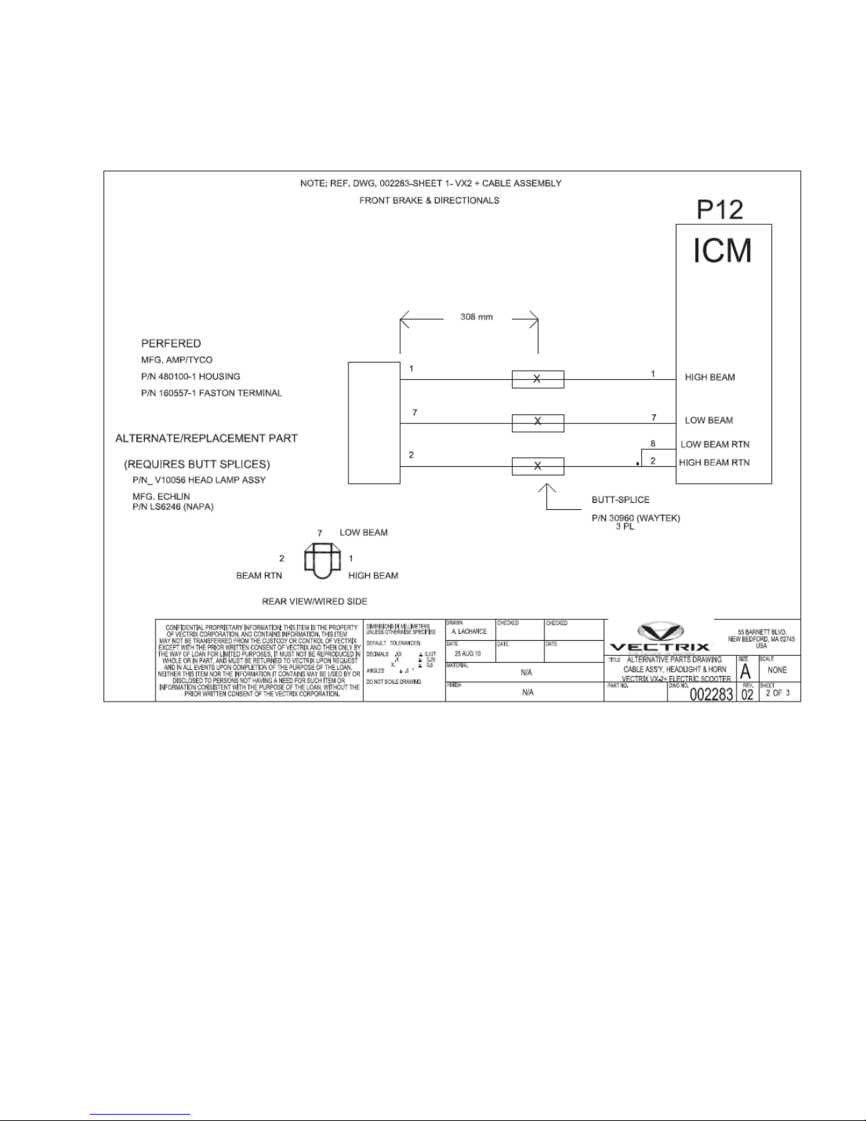
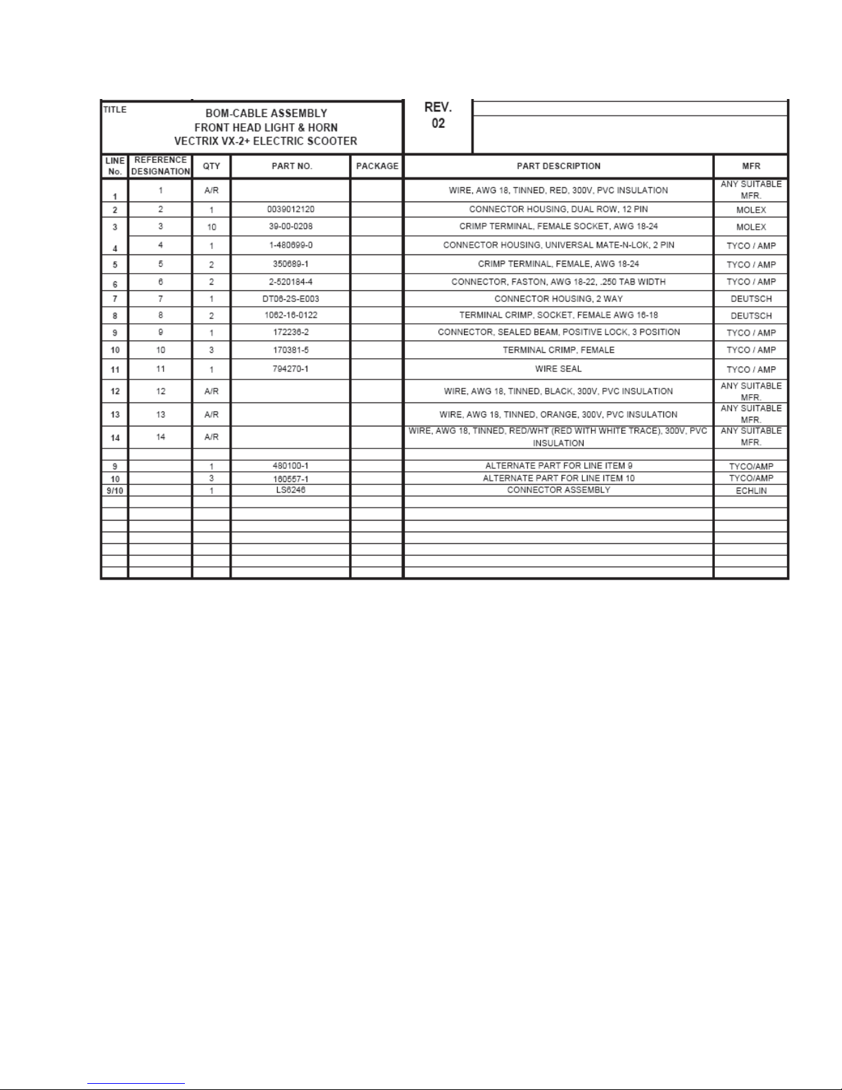
2 Cable Assembly-Front Headlamp + BOM
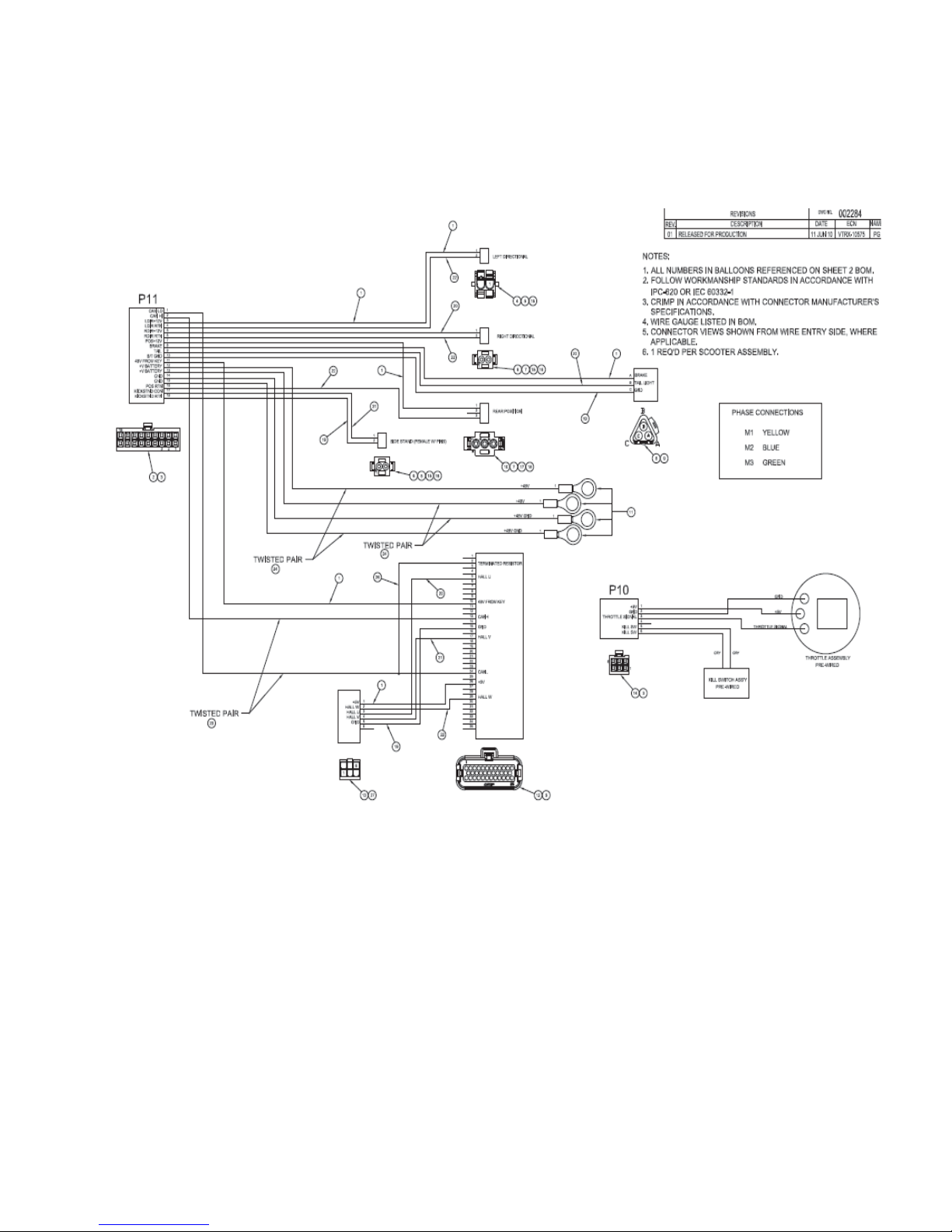
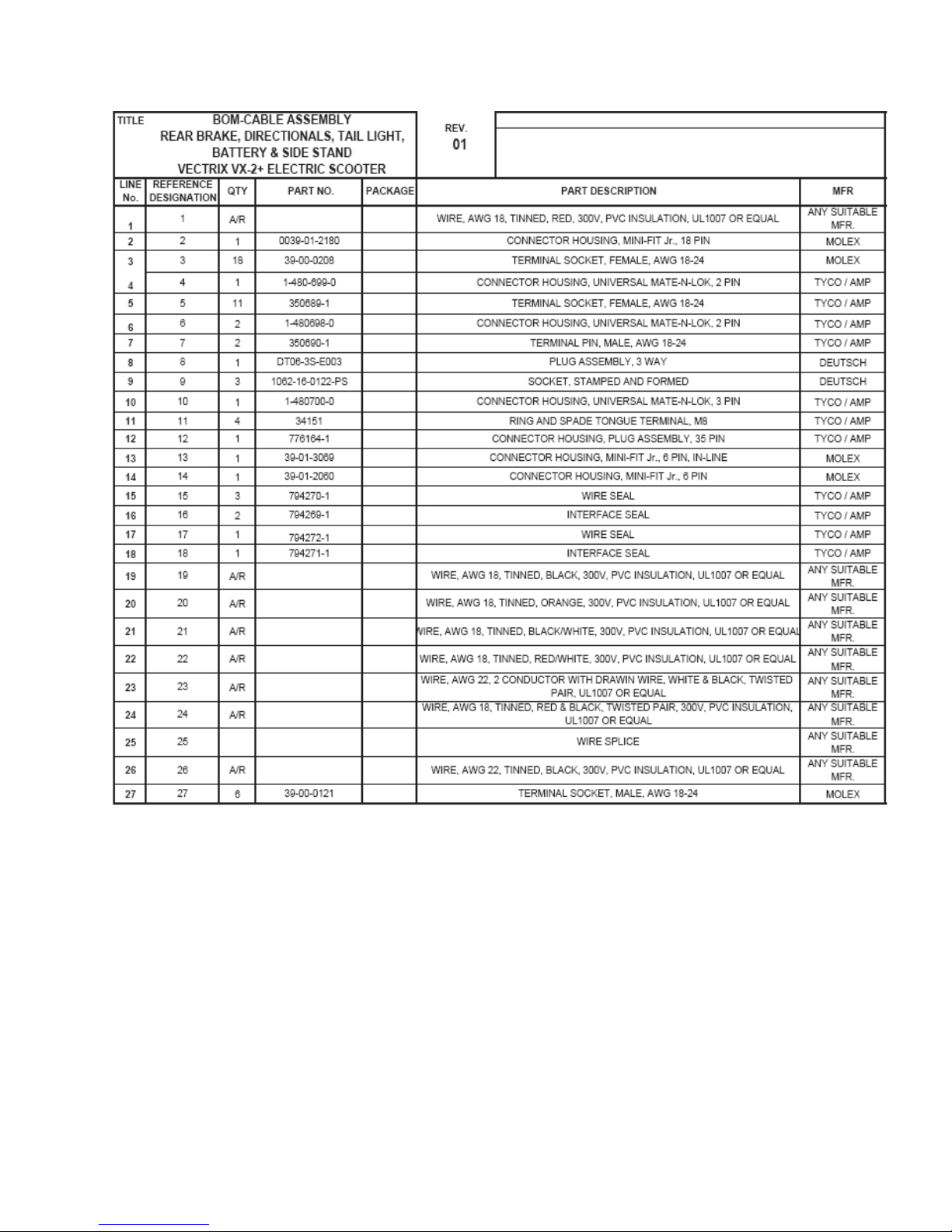
3 Cable Assembly-Rear Brake/Indicators/Battery/Side Stand + BOM
4 Torque List
SECTION G: Unpacking/Prep
1 Unpacking Instructions
2 Prep Instructions
Version 1.0/May 2011
VECTRIX, LLC
Page 4

VECTRIX VX-2 SERVICE MANUAL
SECTION A-1:
TOOLS NEEDED
For repairing and testing of the VX-2 scooter the following tools are needed:
Tools:
Description Specification Using for
Open wrench 5.5mm Converter
Open wrench/Turned Fullcontact (#S02445)
Open wrench 10mm Rear light; Front fender
Open wrench 12mm Rear shock, top; Main stand; Front brake
Open wrench 13mm Rear shock; Main stand; Front shock
Open wrench 14mm Front axle; Battery
Open wrench 16mm Front shock
Open wrench 17mm Side stand; Front axle; Battery
Open wrench 18mm Rear fork
Open wrench 19mm Rear fork
Open wrench 32mm Steering nut, top
Open wrench 45mm Steering nut, bottom
Special tool Motor nut
8mm Speedometer; Cover; Side stand; Horn
Torque wrench 0-20Nm
Torque wrench 10-100Nm
Spanner socket 12mm
Spanner socket 13mm
Spanner socket 14mm
Spanner socket 17mm
Allen key 2.5mm Accelerator
Allen key 4mm Plastic rear cover; Brake hose clamp; Motor
Allen key 5mm Balance weight; Controller
Allen key 6mm Front brake disc, Rear brake
Phillips screwdriver #1 Cover
Phillips screwdriver #2 Cover
Phillips screwdriver #3 Cover
Screwdriver, flat 4.5mm Front top cover
Security TORX Screwdriver TX10 Cover for electronic box
Version 1.0/May 2011
VECTRIX, LLC
Page 5
VECTRIX VX-2 SERVICE MANUAL
SECTION B-1:
FRONT FAIRING
For safety put a plastic or other soft material onto the
fender
Unscrew the 6 Phillips screws 1 to 8 in order as seen on
the picture with a Phillips screwdriver PH2
Remark:
While loosening screws 7 and 8 hold the front cover
otherwise it drops down and could break!
Remark:
While loosening screws 7 and 8 hold the front cover
otherwise it drops down and could break!
87
5
4
1
6
3
2
Assemble all parts in the other direction
Remark:
For assembling the cover please take care of the noses being in the right position
and no edge is standing out. Put in the screws slightly and if all screws and the
cover are in the correct positions tighten them.
See also the last picture on the next Section for the right position of the clamp
screw.
Version 1.0/May 2011
VECTRIX, LLC
Page 6

VECTRIX VX-2 SERVICE MANUAL
Front Fairing Complete Removal
Preparations:
Disassemble Under Board see Section B-10
Disassemble Front Fender see Section B-8
Disassemble Front Wheel see Section B-14
Hold the front cover and loosen all the connectors of the
lamps
Assemble all parts in the other direction
Remark:
Please be sure the clamp nuts are on the right position
For assembling the cover please take care of the noses being in the right position
and no edge is standing out. Put in the screws slightly and if all screws and the
cover are in the correct positions tighten them.
Version 1.0/May 2011
VECTRIX, LLC
Page 7

VECTRIX VX-2 SERVICE MANUAL
SECTION B-2:
FRONT CONSOLE COVER
Preparations:
Disassemble the Front Fairing see Section B-1
Unscrew the two Phillips screws (left and right position)
with a Phillips screwdriver PH2
Slide in a flat screwdriver into the position as seen on the
picture. Hold the front cover by hand. Carefully turn the
screwdriver counter-clockwise [ccw] (left side) and
clockwise [cw] (right side) until the front cover snaps out.
Assemble all parts in the other direction
Remark:
For assembling the top cover, please take care the noses are in the right position
and no edge is standing out.
Version 1.0/May 2011
VECTRIX, LLC
Page 8

VECTRIX VX-2 SERVICE MANUAL
SECTION B-3:
SPEEDOMETER COVER
Preparations:
Disassemble Front Fairing see Section B-1
Disassemble Front Console Cover see Section B-2
Open the connector from Speedometer
Unscrew the Phillips screw with Phillips screwdriver PH2
Unscrew the Phillips screw with Phillips screwdriver PH2
Remove the plastic part including Speedometer
Version 1.0/May 2011
VECTRIX, LLC
Page 9

VECTRIX VX-2 SERVICE MANUAL
SECTION B-4:
FRONT VERTICAL PANEL COVER-LOWER
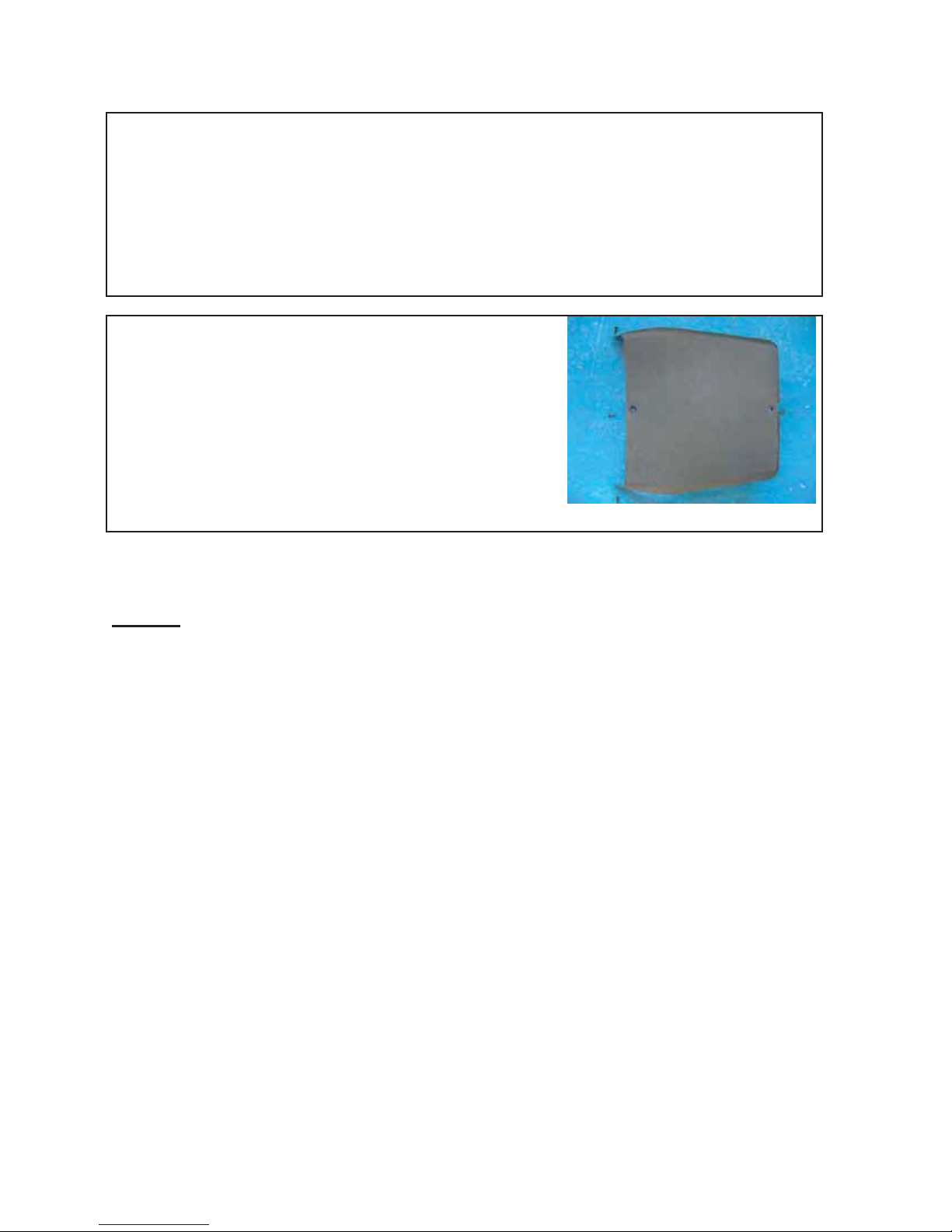
Unscrew the two Phillips screws (up and down position)
with a Phillips screwdriver PH2
Unscrew the two Phillips screws (right and left position)
with a Phillips screwdriver PH2
Slide a Phillips screwdriver PH2 into the hole and pull out
carefully the cover to the left. The fingers holding the cover
and pull backwards
Carefully push back the cover more and more
Version 1.0/May 2011
VECTRIX, LLC
Page 10
VECTRIX VX-2 SERVICE MANUAL
Now remove the cover backwards
The four Phillips screws are M6x16mm
Assemble all parts in the other direction
Remark:
For assembling the cover please take care of the noses being in the right position
and no edge is standing out. Put in the screws slightly and if all screws and the
cover are in the correct positions tighten them.
Version 1.0/May 2011
VECTRIX, LLC
Page 11

VECTRIX VX-2 SERVICE MANUAL
SECTION B-5:
FRONT VERTICAL PANEL COVER-UPPER
Preparations:
Disassemble Front Fairing see Section B-1
Carefully move the cover of Key Switch out
Remove the cover of Key Switch
Side view of the inner backside cover
Version 1.0/May 2011
VECTRIX, LLC
Page 12

VECTRIX VX-2 SERVICE MANUAL
Unscrew the two Phillips screws (left and right position)
with a Phillips screwdriver PH2
Remove the cover
Assemble all parts in the other direction
Version 1.0/May 2011
VECTRIX, LLC
Page 13

VECTRIX VX-2 SERVICE MANUAL
SECTION B-6:
CENTER STEP-THROUGH COVER
Preparations:
Disassemble Seat see Section B-8
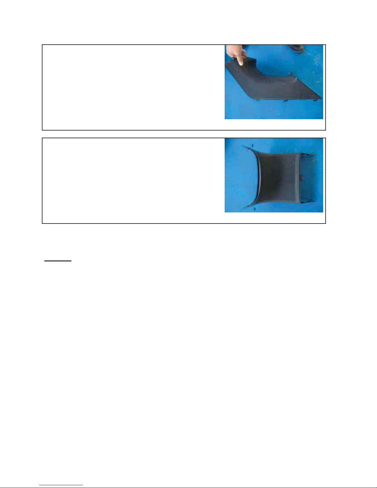
Unscrew the two Phillips screws (left and right position)
with a Phillips screwdriver PH2
Slightly press out left and right side of the cover so that
they can pass the metal holder
Carefully move the cover forward until the cover can easily
be taken out
Version 1.0/May 2011
VECTRIX, LLC
Page 14
VECTRIX VX-2 SERVICE MANUAL
Side view of the inner backside cover
The two Phillips screws are M6 x 16mm
Assemble all parts in the other direction
Remark:
For assembling the cover please take care of the noses being in the right position
and no edge is standing out. Put in the screws slightly and if all screws and the
cover are in the correct positions tighten them.
Version 1.0/May 2011
VECTRIX, LLC
Page 15
VECTRIX VX-2 SERVICE MANUAL
SECTION B-7:
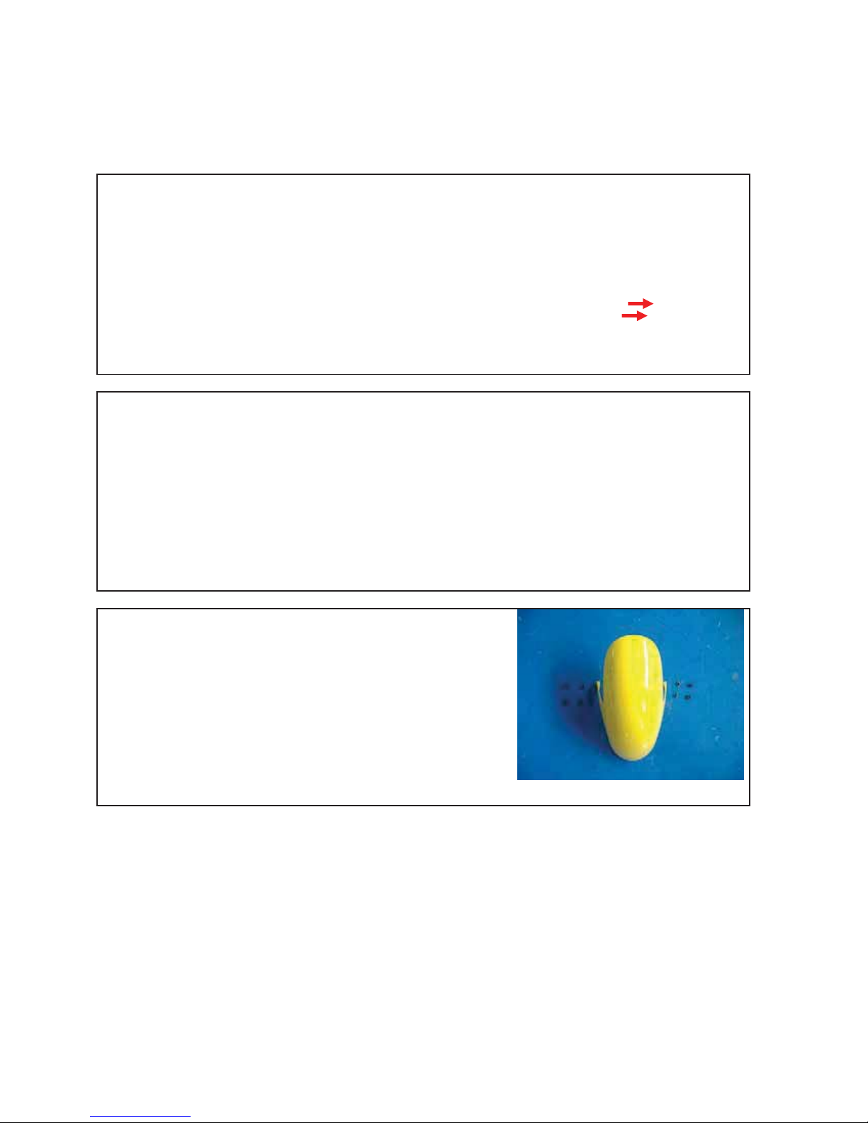
FRONT FENDER
Unscrew the four Phillips screws (left and right side) with a
Phillips screwdriver PH2
To unscrew the Phillips screw hold the inner nut with
8mm open wrench.
Assemble all parts in the other direction
Version 1.0/May 2011
VECTRIX, LLC
Page 16

VECTRIX VX-2 SERVICE MANUAL
SECTION B-8:
SEAT
Unscrew the Phillips screw with a Phillips screwdriver PH2
Hold the seat during unscrewing the second Phillips screw
Remove the seat
The two Phillips screws are M6 x 16mm
Assemble all parts in the other direction
Test if the seat lock works smoothly
Version 1.0/May 2011
VECTRIX, LLC
Page 17
VECTRIX VX-2 SERVICE MANUAL
SECTION B-9:
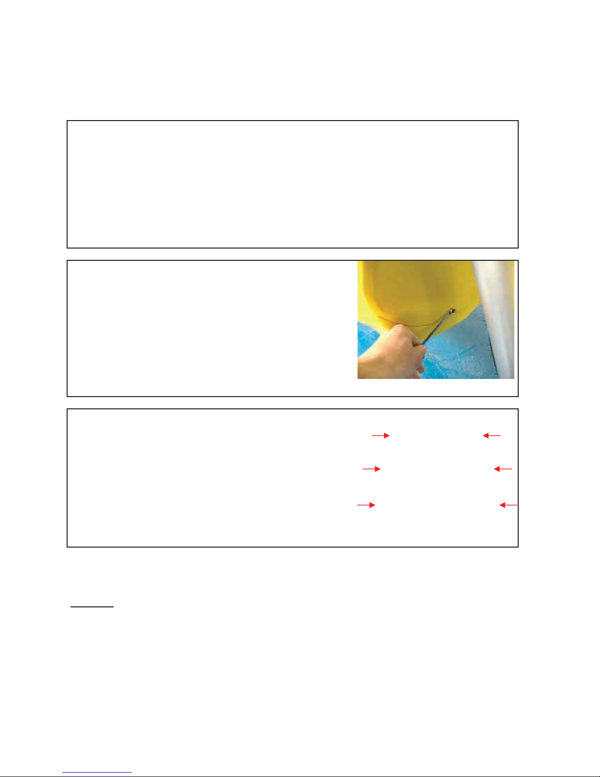
UNDER BOARD
Unscrew the two Phillips screws (left and right position)
with a Phillips screwdriver PH2
Unscrew the screw (Front position) with a 8mm wrench
Unscrew the 6 Phillips screws in order as seen on the
picture with a Phillips screwdriver PH2
While loosening screws 5 and 6 hold the Under board
1
6
4
5
otherwise it drops down and could break!
2
3
Assemble all parts in the other direction
Remark:
When assembling the cover, please take care of the noses are in the right position and no edge
is outstanding. First, just slightly screw in the screws and if all screws and the cover are in the
correct position tighten the screws.
Version 1.0/May 2011
VECTRIX, LLC
Page 18

VECTRIX VX-2 SERVICE MANUAL
SECTION B-10:
REAR SIDE BODY PANELS + SIDE EMBLEM REPLACEMENT
Unscrew the four Phillips screws (top left and right
position) with a Phillips screwdriver PH2
Unscrew the four Phillips screws (left and right position)
with a Phillips screwdriver PH2
Carefully pull out left and right side until the cover can
easily lift up
Remark:
Be careful for the left side because there is
the seat lock
Version 1.0/May 2011
VECTRIX, LLC
Page 19

VECTRIX VX-2 SERVICE MANUAL
The four Phillips screws for the top are plate screw 3.5 x
12mm
The four Phillips screws for the side are plate screw 3.2 x
12mm (black)
Assemble all parts in the other direction
Put in the screws slightly and if all screws and the cover are in the correct positions tighten
them.
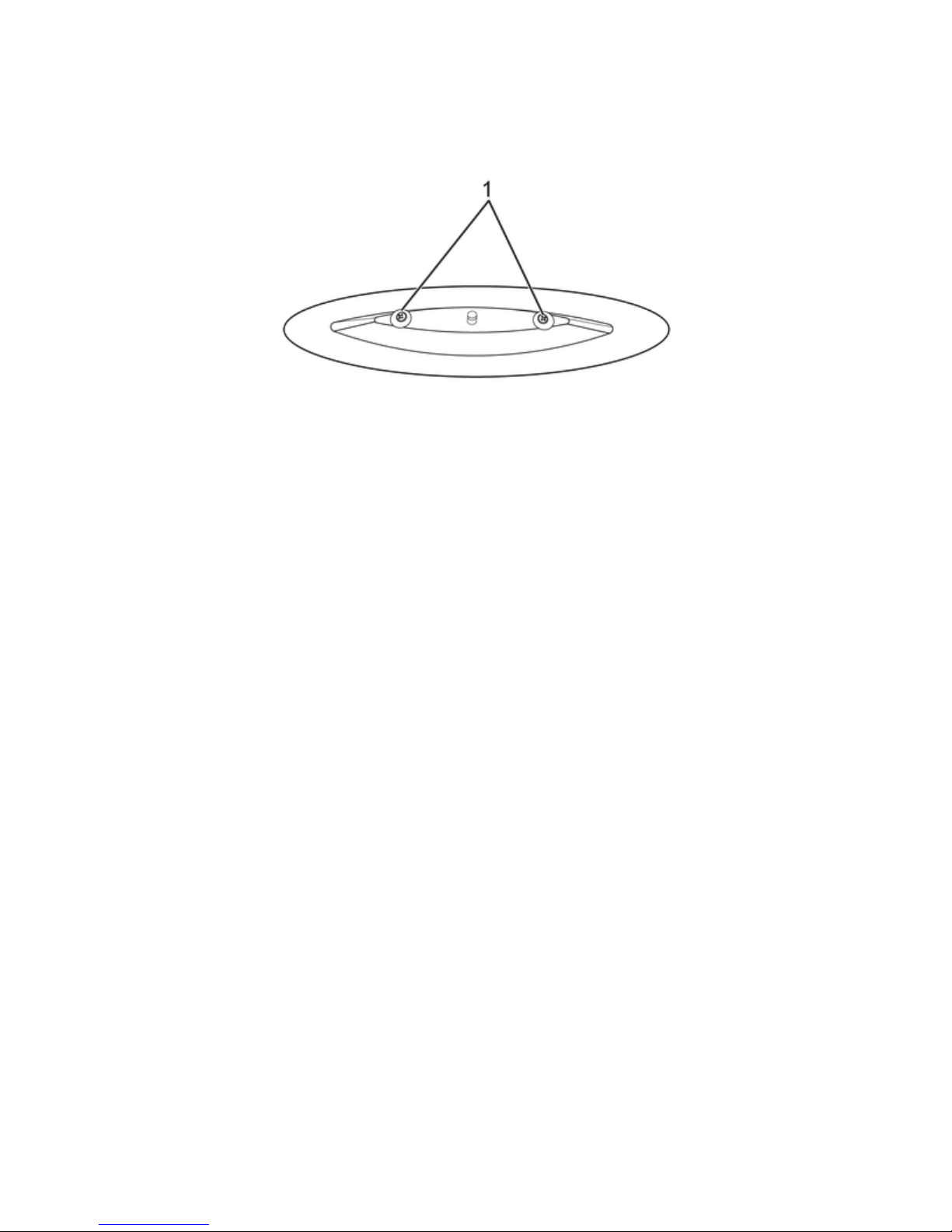
Rear Side Panel Emblem/Nameplate Replacement
S-XC-S00329
Removal Procedure
1. Right side:
Remove the right rear & cheek panel. Refer to Rear & Cheek Panel Right Replacement in Body
Rear End.
Left side:
Remove the left rear & cheek panel. Refer to Rear Cheek Panel Left Replacement in Body Rear
End.
2. Remove the 2 screws (1) and remove the Emblem/Nameplate.
Version 1.0/May 2011
VECTRIX, LLC
Page 20
VECTRIX VX-2 SERVICE MANUAL
Installation Procedure
1. Align the Emblem/Nameplate and install the 2 screws (1).
2. Right side:
Install the right rear & cheek panel. Refer to Rear & Cheek Panel Right Replacement in Body
Rear End.
3. Left side:
Install the left rear & cheek panel. Refer to Rear & Cheek Panel Left Replacement in Body Rear
End.
Version 1.0/May 2011
VECTRIX, LLC
Page 21

VECTRIX VX-2 SERVICE MANUAL
SECTION B-11:
REAR FENDER
Preparations:
Disassemble Side Body Panels + Side Emblems see Section B-10
Disconnect all connectors of the lights
Unscrew the 3 screws with a 8mm open wrench
and open all the connections
Assemble all parts in the other direction
Version 1.0/May 2011
VECTRIX, LLC
Page 22
VECTRIX VX-2 SERVICE MANUAL
SECTION B-12:
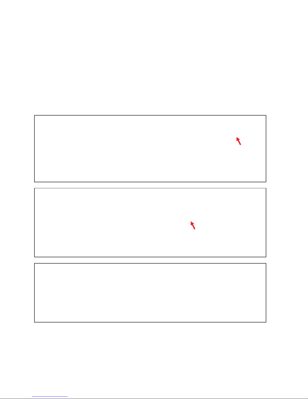
FRONT BRAKE
Preparations:
Disassemble Front Fairing see Section B-1
Disassemble Front Console Cover see Section B-2
Disassemble Speedometer Cover see Section B-3
Disassemble Front Fender see Section B-7
Remove hex screw of the hose clamp with 8mm open
wrench
Remove the brown cables of the front brake switch and
cut all cable clamps
Unscrew both hex screws with an Allen key 5mm
Version 1.0/May 2011
VECTRIX, LLC
Page 23
VECTRIX VX-2 SERVICE MANUAL
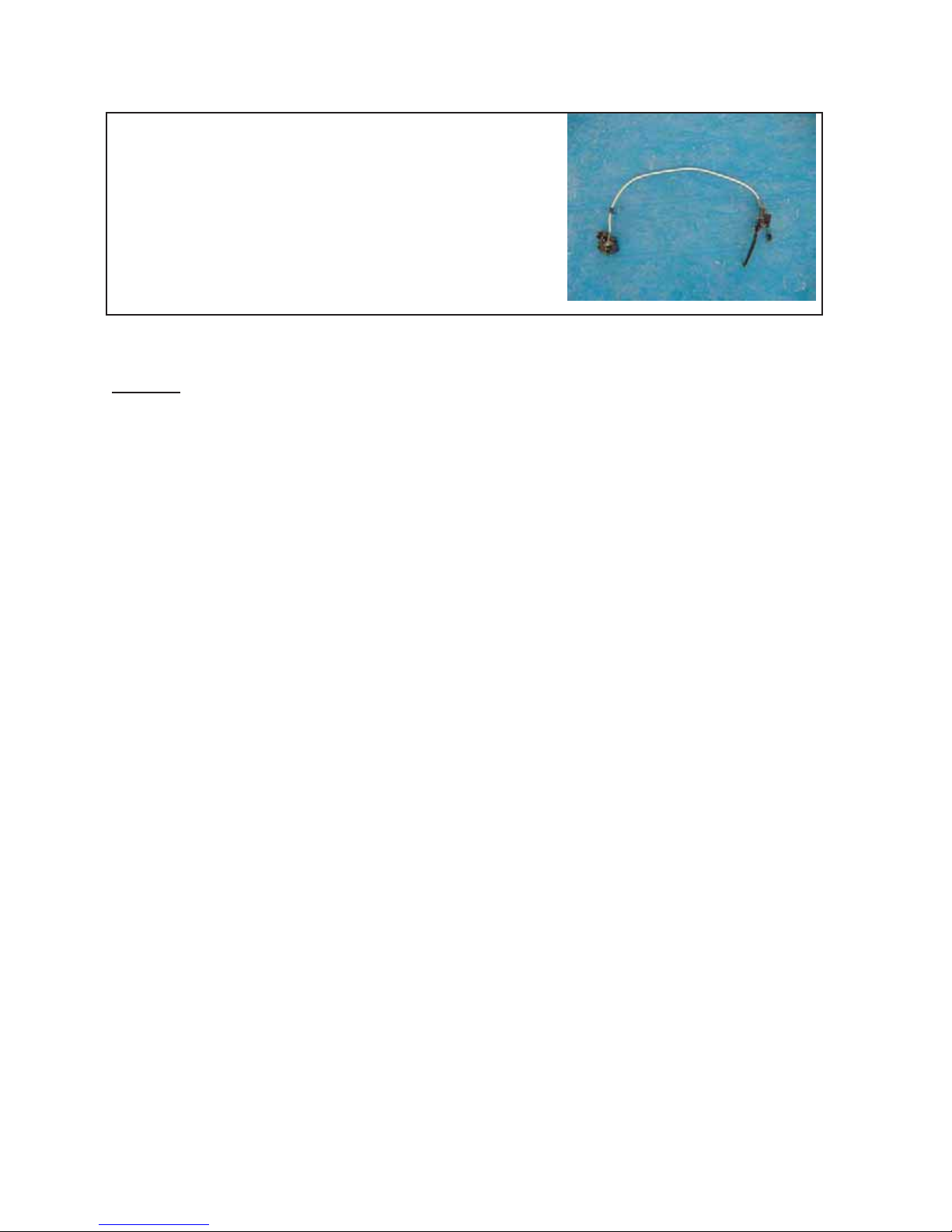
Parts of complete front brake
Assemble all parts in the other directions
Remark:
no edge is outstanding. Put in the screws a little bit and if all screws and the cover are in the
correct positions tighten it.
For assembling the cover please be careful of the noses are in the right position and
Version 1.0/May 2011
VECTRIX, LLC
Page 24

VECTRIX VX-2 SERVICE MANUAL
SECTION B-13:
FRONT WHEEL
Preparations:
Disassemble Front Fender see Section B-7
Remove both plastic covers from the screw
Open the two Hex screw with open wrench
12 mm and remove the brake
2
1
Put the scooter on a supporter and lift up the scooter until
the front wheel is moves freely
Unscrew the nut of the right side by using open wrench
17mm and hold the screw with open wrench 14mm
Version 1.0/May 2011
VECTRIX, LLC
Page 25

VECTRIX VX-2 SERVICE MANUAL
Remove screw (axle) and the other parts and the wheel
Version 1.0/May 2011
VECTRIX, LLC
Page 26
VECTRIX VX-2 SERVICE MANUAL
SECTION B-14:
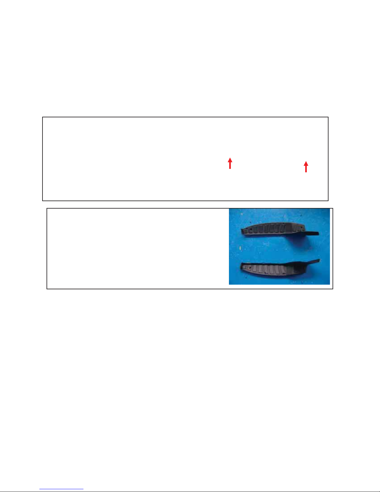
FOOT REST
Preparations:
Disassemble Center Step-Through Cover see Section B-6
Disassemble Under Board see Section B-9
Open the two screws 1 + 2 and the two screws for the side
shields with PH2 screw driver
Same procedure for the other side if necessary
Assemble all parts in the other direction
2
1
Version 1.0/May 2011
VECTRIX, LLC
Page 27

VECTRIX VX-2 SERVICE MANUAL
SECTION B-15:
SIDE COVER
Unscrew the 4 screws by using a Phillips screwdriver 2
Unscrew the 3 screws by using a Phillips screwdriver 2
(1 screw is covered by the main stand)
Assemble all parts in the other direction
Version 1.0/May 2011
VECTRIX, LLC
Page 28

VECTRIX VX-2 SERVICE MANUAL
SECTION B-16:
REAR BRAKE
Note: To replace the Rear Brake Rotor see Motor Replacement Procedure C-16
Unscrew the two inner hexagon bolts by using an Allen
key 6mm
Disassemble the rear brake
Now it is possible to exchange the brake pads
Remark
It is not necessary to disassemble the side cover of the
rear fork as seen on the picture
Assemble all parts in the other direction
:
Version 1.0/May 2011
VECTRIX, LLC
Page 29

VECTRIX VX-2 SERVICE MANUAL
Preparations: (for complete removal)
Disassemble Left Foot Rest see Section B-14
Disassemble Rear Suspension see Section B-18
Remove the connector from the Speedometer
Remove the two cross screws by using a Phillips
screwdriver #2 and remove the complete Speedometer
cover
Remove the two connectors from the brake switch
Remove all strips for cable and brake hose
Remove the two inner hex cap screws from the brake
lever assembly by using an Allen key 5mm
Version 1.0/May 2011
VECTRIX, LLC
Page 30
VECTRIX VX-2 SERVICE MANUAL
Move the brake hose including the complete brake lever
assembly through the frame
Attention
Do not open the brake system inside the scooter. The
brake liquid could damage the paint or other parts.
Move the brake hose including the complete brake lever
assembly through the frame and rear suspension
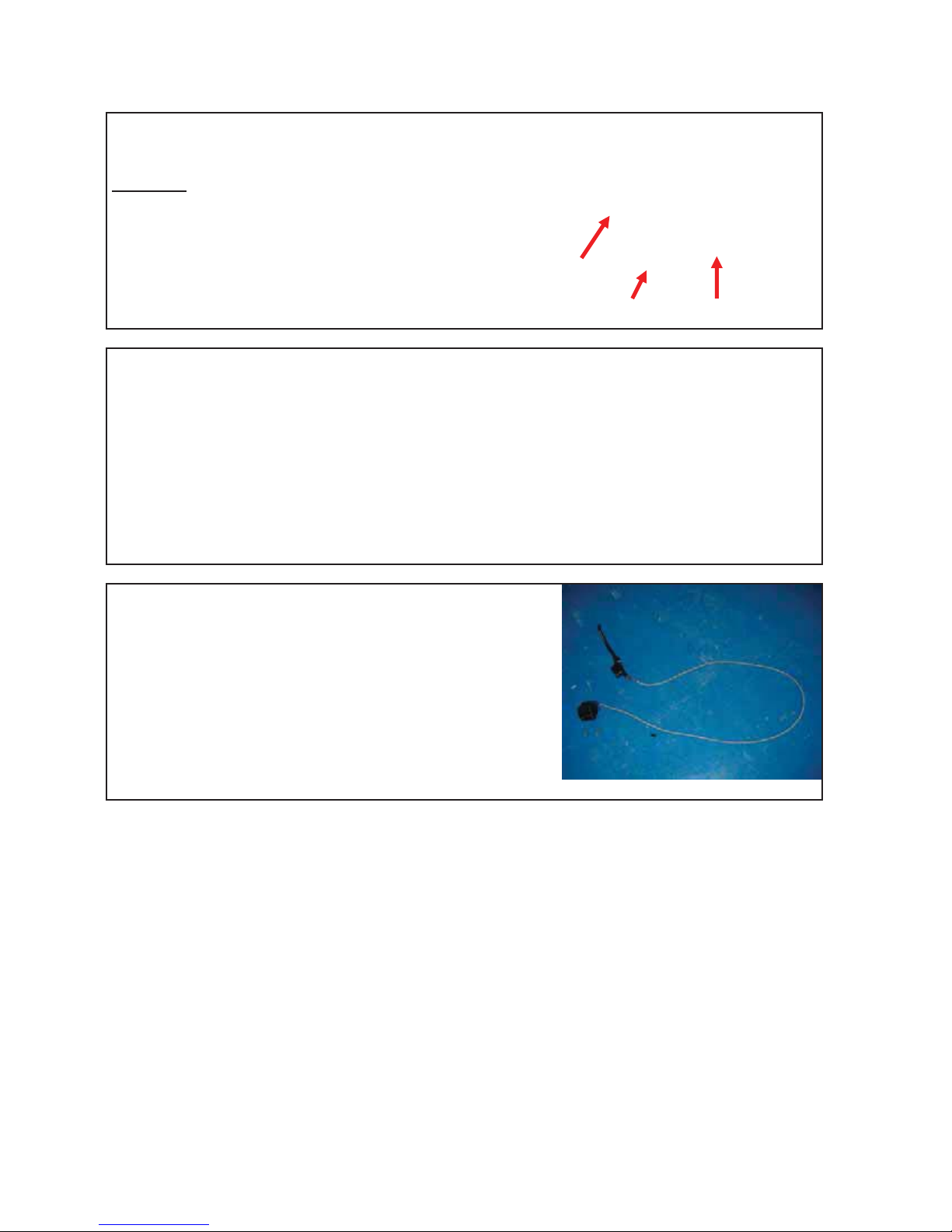
Complete removed rear brake assembly
:
Assemble all parts in the other directions and tighten the bolts and the nut according to the
regulated torque, see Section F-4
Version 1.0/May 2011
VECTRIX, LLC
Page 31
VECTRIX VX-2 SERVICE MANUAL
SECTION B-17:
REAR SHOCK
Preparations:
Disassemble Left Side Body Panel see Section B-10
Unscrew the nut #1 by using a open wrench 14mm
Unscrew the bolt #2 by using a open wrench 13mm
Unscrew the bolt #3 by using a open wrench 12mm and
remove rear shock
3
Remark
For disassembling of the rear shock it is not necessary
to remove the motor and the side cover
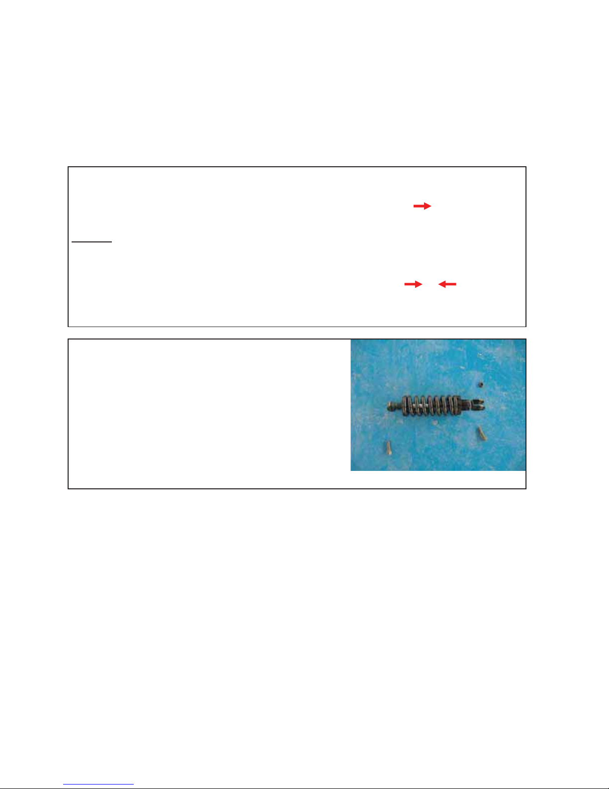
All parts of removed rear shock
Assemble all parts in the other directions and tighten the bolts and the nut according to the
regulated torque, see Section F-4
:
2
1
Version 1.0/May 2011
VECTRIX, LLC
Page 32
VECTRIX VX-2 SERVICE MANUAL
SECTION B-18:
REAR SUSPENSION
Preparations:
Disassemble Motor see Section C-16
Unscrew 3 inner hex cap bolts and nuts by using an
Allen key 4mm and an open wrench 10mm
Remove the Plastic cover, rear suspension
Remark
Put up the back of the battery case on a supporter
Unscrew the nut #1 by using a open wrench 14mm
Unscrew the bolt #2 by using a open wrench 13mm and
remove the bolt
Remark
It is not necessary to remove any covers or battery
Unscrew the two nuts and hexagon bolts by using 18mm
and 19mm open wrench and remove the rear suspension
:
:
2
1
Remark
It is not necessary to remove any covers or battery
:
Version 1.0/May 2011
VECTRIX, LLC
Page 33
VECTRIX VX-2 SERVICE MANUAL
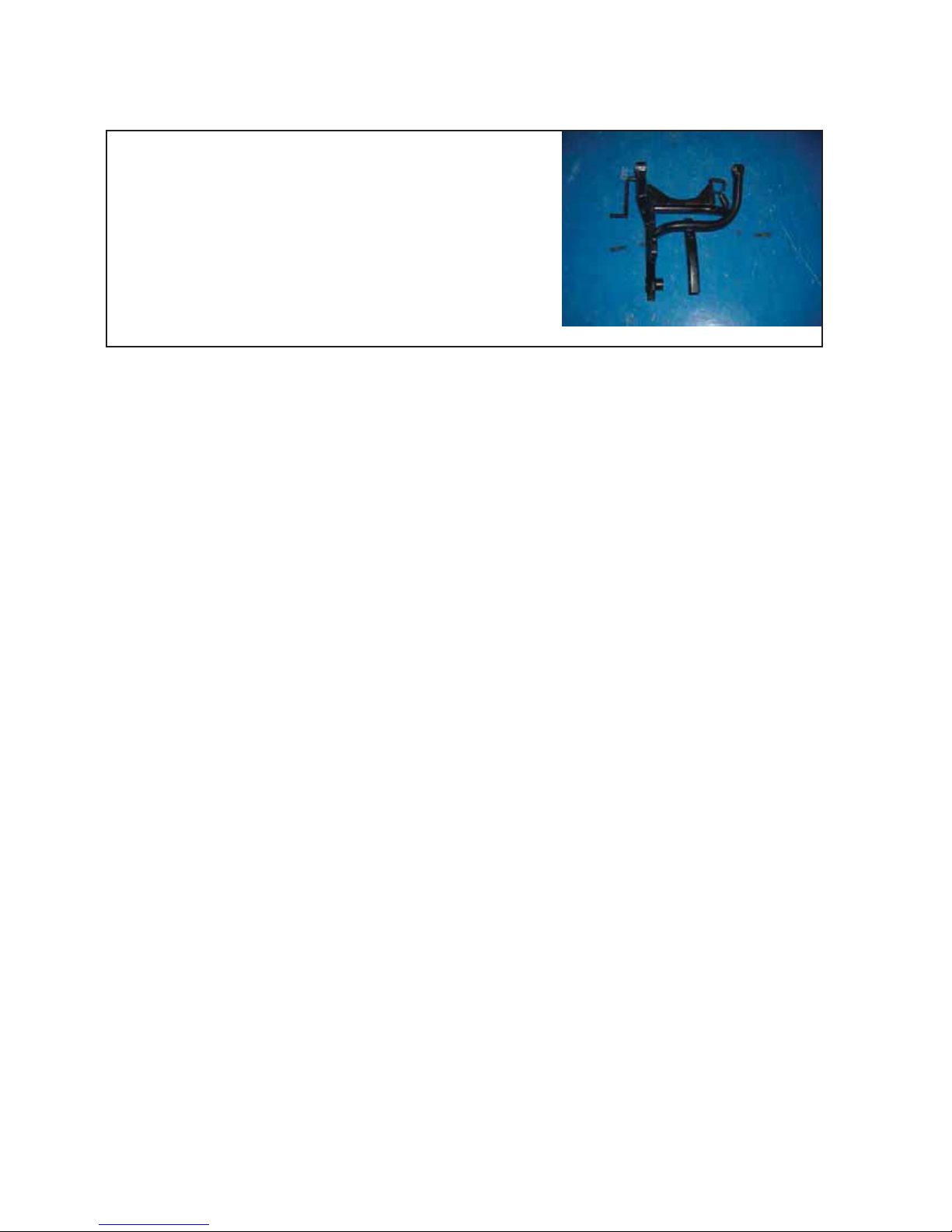
All parts of rear suspension
Assemble all parts in the other direction and tighten the bolts and nuts according to the
regulated torque, see Section F-4
Version 1.0/May 2011
VECTRIX, LLC
Page 34
VECTRIX VX-2 SERVICE MANUAL
SECTION B-19:
HANDLEBAR
Preparations:
Disassemble Front Console Cover see Section B-2
Disassemble Front Vertical Panel-Lower see Section B-4
Disassemble Front Vertical Panel-Upper see Section B-5
Open the connector from the Speedometer
Remove the two cross screws by using a Phillips
screwdriver #2 and remove the complete Speedometer
cover
Remove all parts of the handlebar
- Left- and right switch assembly
- Left- and right brake handle assembly
- Accelerator
- Left side grip
Remark
It is not necessary to remove any covers
Unscrew the nut #2 by using a open wrench 13mm
Unscrew the bolt #1 by using a open wrench 13mm and
remove the bolt
:
2
1
Assemble all parts in the other direction and tighten the bolts and nuts according to the
regulated torque, see Section F-4
Version 1.0/May 2011
VECTRIX, LLC
Page 35

VECTRIX VX-2 SERVICE MANUAL
SECTION C-1:
SPEEDOMETER
Preparations:
Disassemble Front Fairing see Section B-1
Disassemble Front Console Cover see Section B-2
Remove connector from Speedometer
Unscrew the Phillips screw with Phillips screwdriver PH2
Unscrew the Phillips screw with Phillips screwdriver PH2
Remove the plastic part with Speedometer
Version 1.0/May 2011
VECTRIX, LLC
Page 36

VECTRIX VX-2 SERVICE MANUAL
Unscrew both nuts with 8mm open wrench
Remove the plastic bracket
Remark:
Carefully remove the Speedometer out of the plastic cover
On the underside of the plastic bracket there
are two plastic noses which fit into two holes of
the plastic cover. These noses fixed the
Speedometer in the right position.
Assemble all parts in the opposite directions
Test functions of speedometer
Version 1.0/May 2011
VECTRIX, LLC
Page 37

VECTRIX VX-2 SERVICE MANUAL
SECTION C-2:
THROTTLE
Preparations:
Disassemble Front Fairing see Section B-1
Disassemble Front Vertical Panel-Lower see Section B-4
Disassemble Front Vertical Panel-Upper see Section B-5
Disassemble Front Console Cover see Section B-2
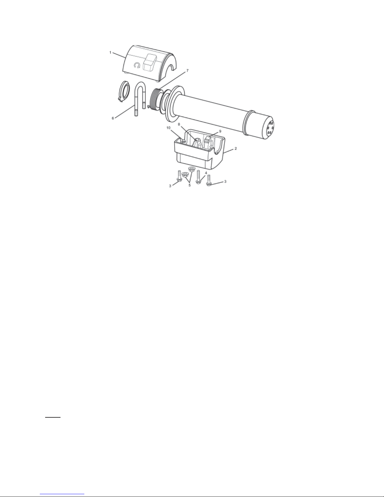
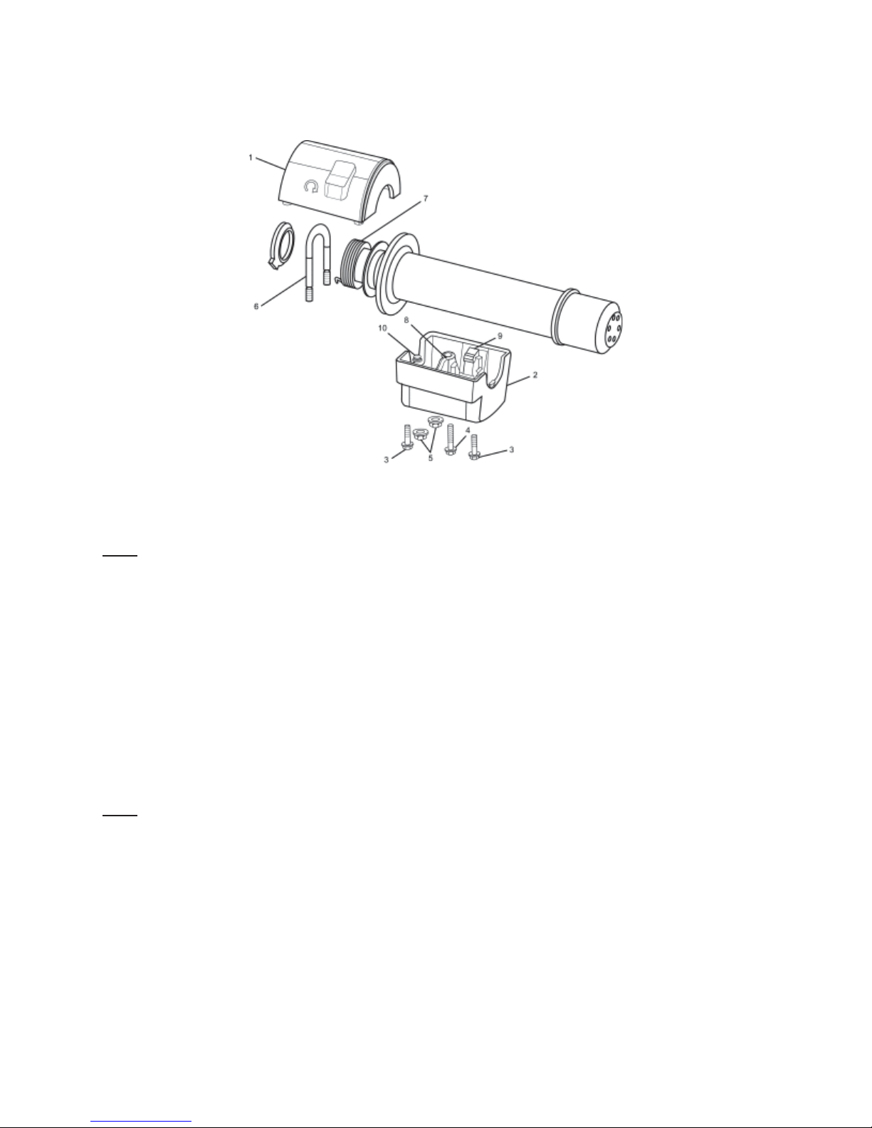
Lower Regen Throttle Box Replacement
S-XC-S00077
Tools Required:
PH #2
8mm Turned Full-contact Hexagonal Socket (S02445)
Removal Procedure
1. Turn ignition key to the off position.
2. Remove three screws (3,4) from the lower throttle box assembly.
3. Lift the kill switch housing (1) up and away from lower box.
4. Using 8mm Hexagonal Socket S02445 remove two lower box U-Bolt nuts (5).
Note the orientation of the throttle return spacers and spring for reassembly.
5. Remove the U-Bolt (6). Pull down on the lower box (2) and remove.
6. Slide the throttle assembly off of the handlebar.
Version 1.0/May 2011
VECTRIX, LLC
Page 38
VECTRIX VX-2 SERVICE MANUAL
Installation Procedure
1. Install the U-Bolt into the box and start one of the nuts on the first thread of the rear stud of
the U-Bolt.
2. Slide the assembly onto the handlebar; ensure that the kill switch harness is installed into the
slot of the lower box.
3. With the lower box pivoted away from the handlebar slide the throttle assembly onto the
handlebar.
4. Position the return spring (7) onto the spring post (8) of the lower box and twist the throttle
until the throttle stop is resting on the lower box throttle stop (9).
5. Ensure that the tab (10) on the bottom of the lower box is into the hole in the handlebar.
6. Using tool 01545, install the other U-Bolt nut and tighten both nuts.
7. Twist the throttle to ensure free movement and that it returns to a neutral position.
8. Using 8mm Hexagonal Socket S02445, install the kill switch cover onto the box and install the
3 screws, tighten. Alternate tightening of the 2 nuts until reaching a torque value of 2 Nm.
9. Check the Regen Throttle adjustment. Refer to Throttle Position Checking Procedure.
: If needed, to remove the old throttle position magnet sensor, install the new sensor
Note
magnet and screw it in until lightly seated, then back out 1 full turn. Continue to unscrew the
throttle position magnet sensor until the throttle is properly aligned.
Version 1.0/May 2011
VECTRIX, LLC
Page 39
VECTRIX VX-2 SERVICE MANUAL
Regen Throttle Adjustment Procedure
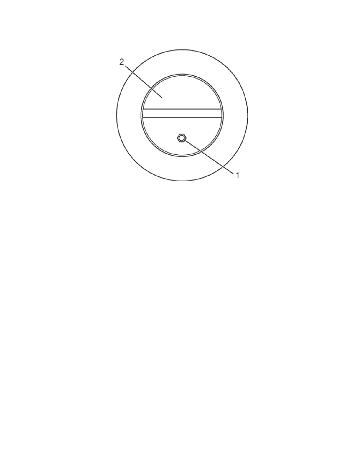
: Key must be in “ON” position and Kill Switch in the “OFF” position
Note
1. Remove the right handlebar end cap. Refer to Handlebar End Cap and Hand Grip
Replacement.
2. Slightly loosen the set screw (1).
3. To determine the current position of the Throttle, squeeze the left side brake lever and using
a large rubber band or similar device secure the lever in the squeezed position, and observe the
needle position.
4. To determine the correct position of the Throttle, squeeze the right side brake lever and
observe the reading.
: The neutral position of the throttle is 615-639. The ideal setting for this adjustment is 625.
Note
5. Release the right lever and adjust the screw (2) until the readings are the same.
6. Remove the large rubber band or similar to release the left side brake lever.
7. Slightly tighten the set screw; this will secure the screw from moving.
8. Install the right handlebar end cap.
Version 1.0/May 2011
VECTRIX, LLC
Page 40
VECTRIX VX-2 SERVICE MANUAL
Version 1.0/May 2011
VECTRIX, LLC
Page 41
VECTRIX VX-2 SERVICE MANUAL
Regen Throttle Sensor Replacement
S-XC-S00079
Removal Procedure
1. Remove the upper handlebar cover. Refer to Front Console Cover Replacement B-2.
2. Remove the right handlebar end cap and hand grip. Refer to Handlebar End Cap and Hand
Grip Replacement.
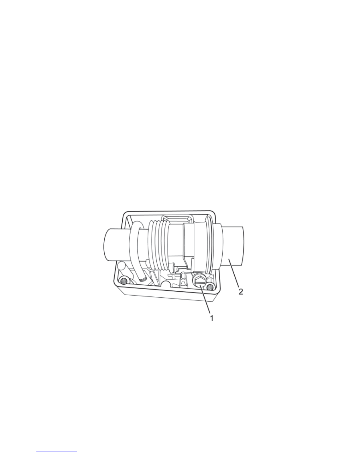
3. Remove the kill switch cover screws.
4. Twist the throttle to gain access to the throttle clamp screw (1) and loosen.
5. Remove the throttle sleeve (2) from the handlebar.
6. Loosen the Throttle set screw (1) and remove the sensor magnet (2).
Version 1.0/May 2011
VECTRIX, LLC
Page 42
VECTRIX VX-2 SERVICE MANUAL
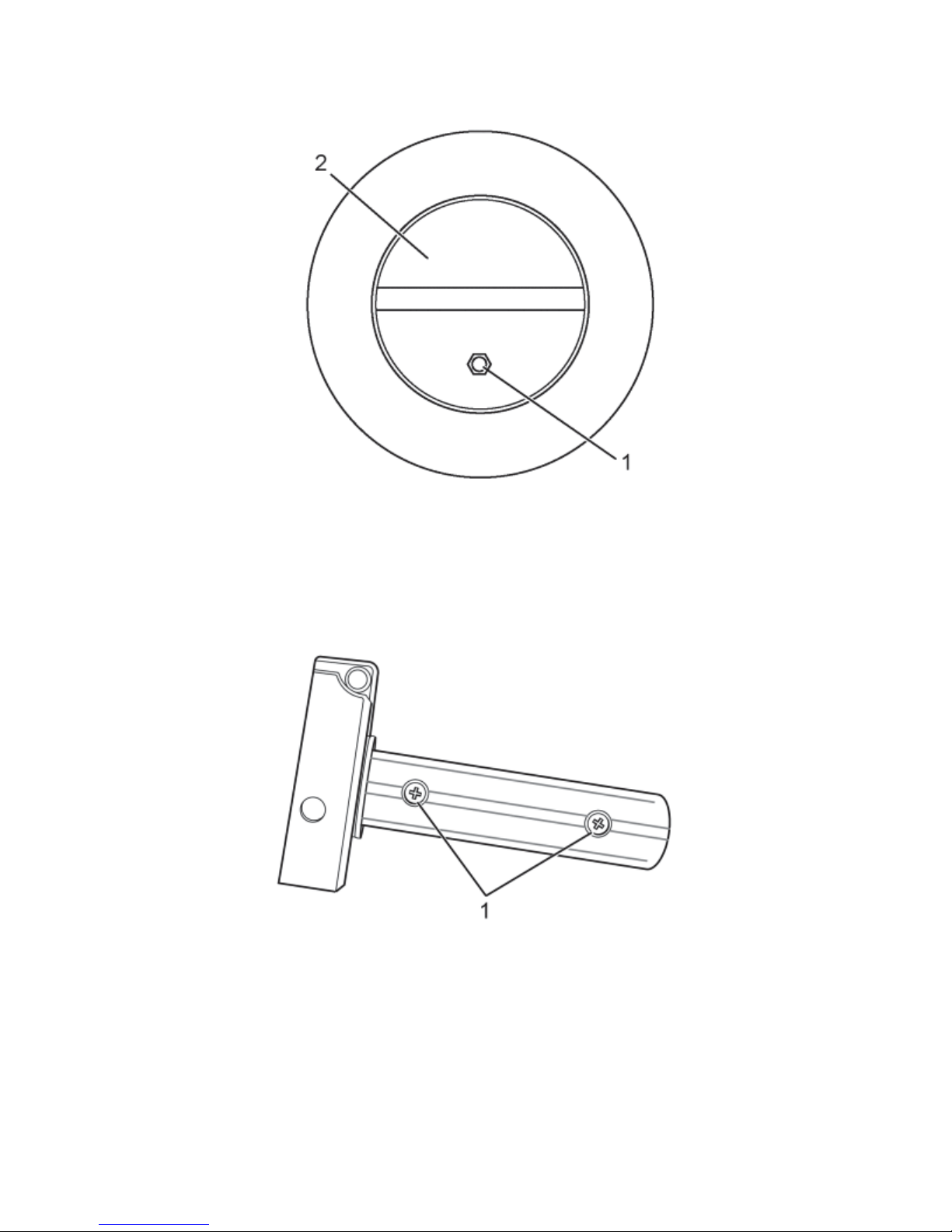
7. Remove the screws (1) and slide the insert and sensor out of the handlebar.
8. Remove the sensor (1) from the insert.
9. Mark and remove the sensor wires from the handlebar connector and remove the sensor.
Version 1.0/May 2011
VECTRIX, LLC
Page 43
VECTRIX VX-2 SERVICE MANUAL
Installation Procedure
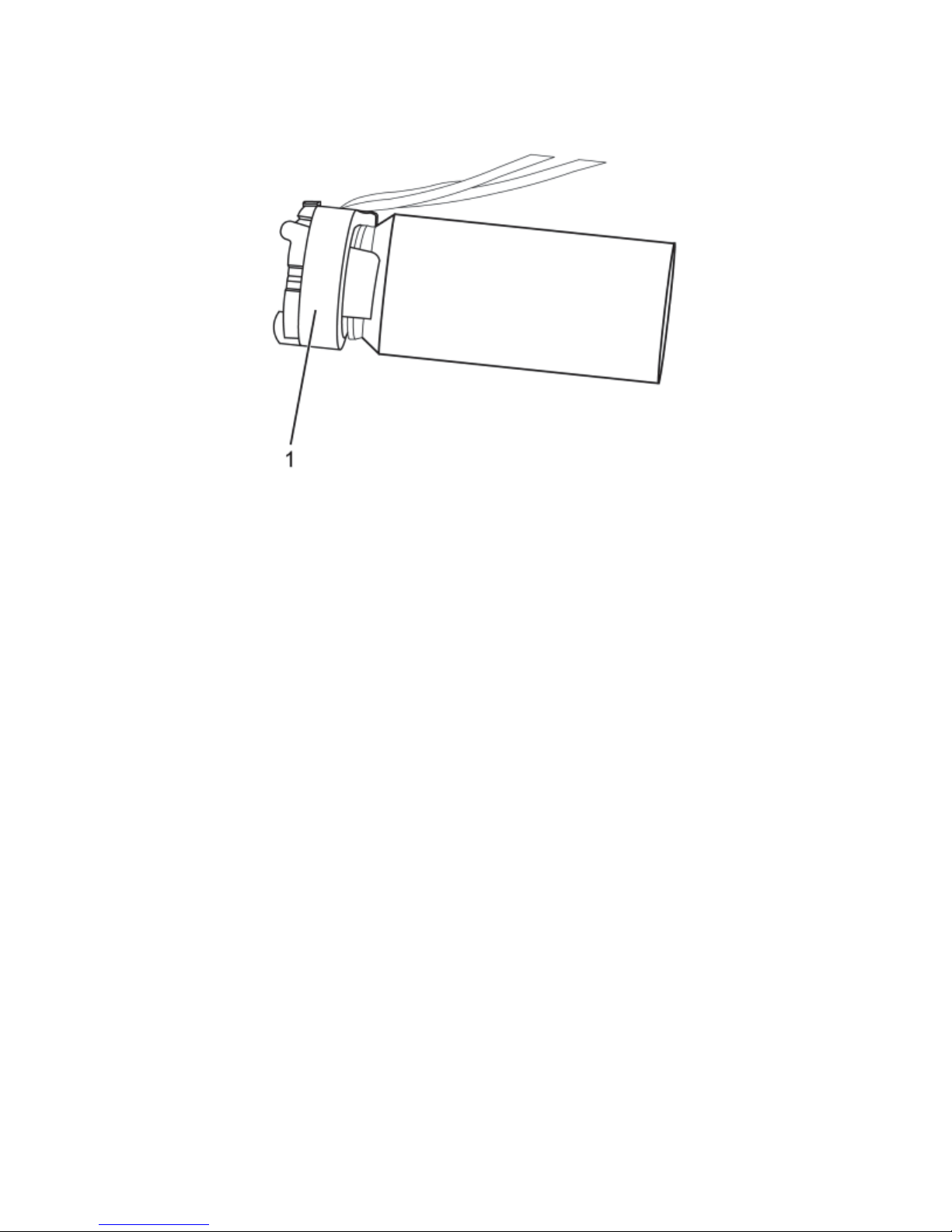
1. Install the sensor wires through the handlebar and out the harness hole.
2. Install the sensor wires into the connector in the same location as removed.
3. Install the sensor (1) onto the insert.
Version 1.0/May 2011
VECTRIX, LLC
Page 44
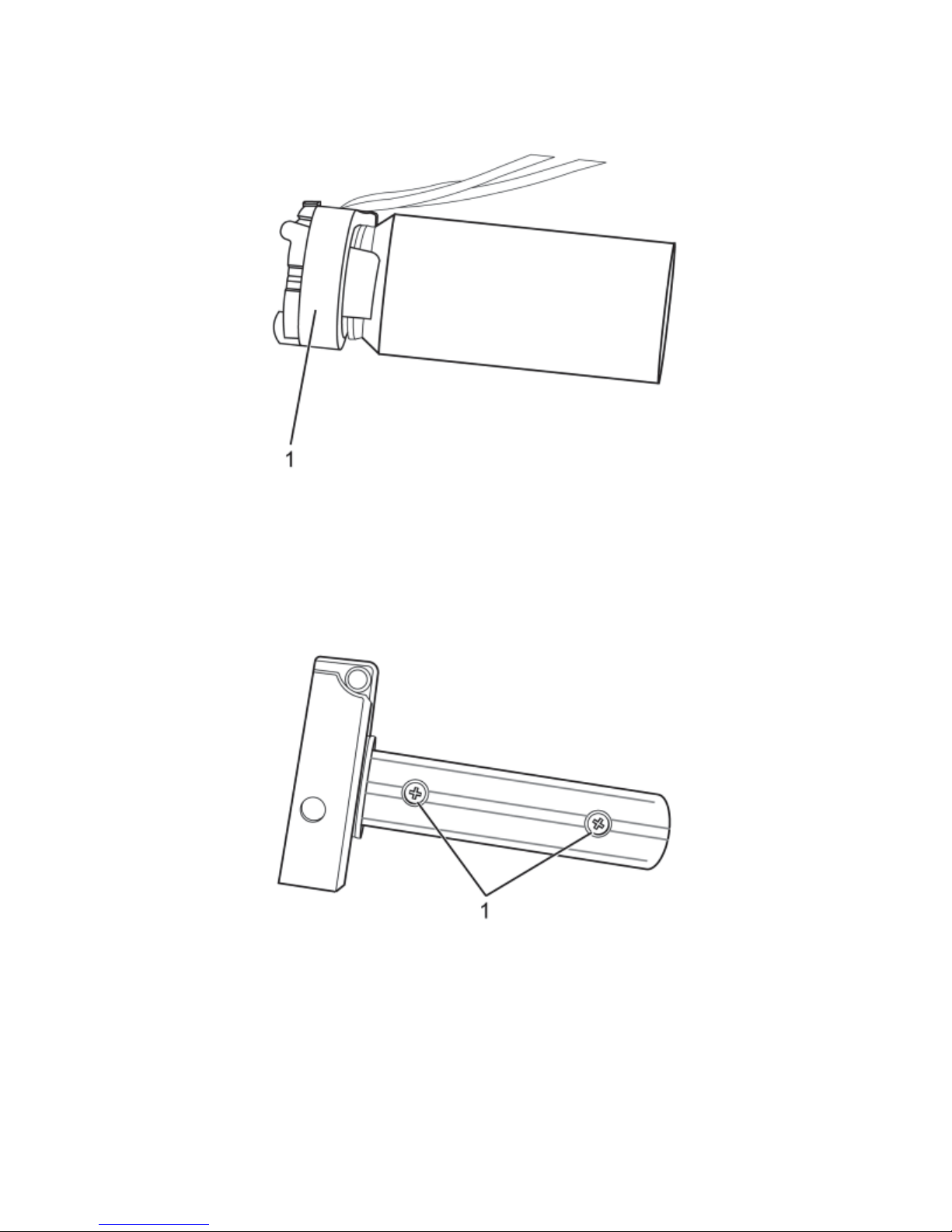
VECTRIX VX-2 SERVICE MANUAL
4. Install the insert and tighten the screws (1).
5. Install the throttle sleeve (2) onto the handlebar and into the plastic sleeve.
Notice: Refer to Fastener Notice in General Information.
Version 1.0/May 2011
VECTRIX, LLC
Page 45
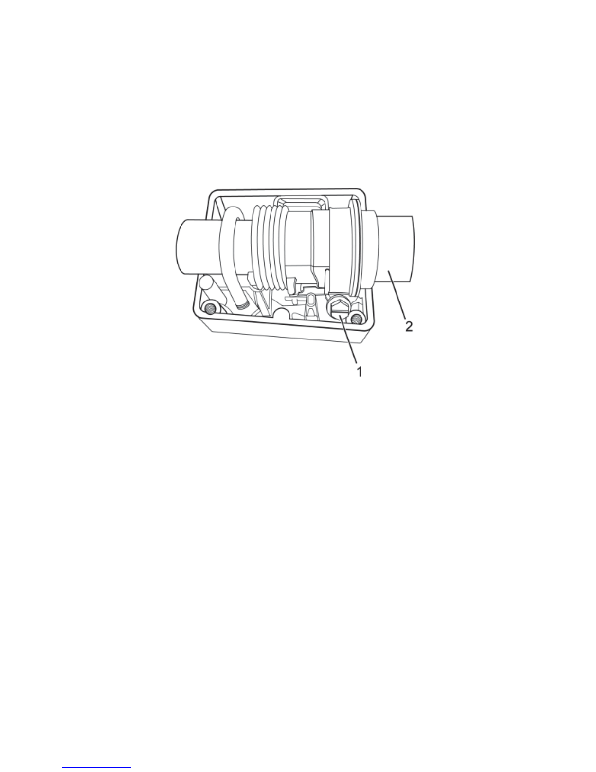
VECTRIX VX-2 SERVICE MANUAL
6. Twist the throttle sleeve into the full Regen position and tighten the throttle clamp screw (1).
Tighten
Throttle clamp screw 2.5 Nm (22 lb in)
7. Install the kill switch cover, and screws and tighten.
8. Verify smoother operation of the throttle.
9. Install the upper handlebar cover. Refer to Front Console Cover Replacement.
10. Install the sensor magnet and screw in until lightly seated then back out 1 full turn.
11. Check the adjustment of the Regen Throttle. Refer to Throttle Position Checking Procedure.
12. Install the right handlebar end cap and hand grip. Refer to Handlebar End Cap and Hand
Grip Replacement.
Version 1.0/May 2011
VECTRIX, LLC
Page 46
VECTRIX VX-2 SERVICE MANUAL
Regen Throttle Position Checking Procedure
S-RW-100000
Without PC
Note
: This procedure is to be used when a PC is not available. This adjustment MUST be
verified using the PC method.
1. Place the ignition key in the ON position and the kill switch in the ON (non-run) position.
2. Squeeze the left side brake lever and observe the speedometer needle (1). This reading is
the actual setting of the Regen Throttle.
3. Continue to squeeze the left side and then squeeze the right side brake lever and observe
the speedometer needle. This is the required setting and what the actual reading in Step 3 must
be set to. If the settings are not the same refer to Throttle Adjustment Procedure.
(1)
With PC
1. Connect the Diagnostic Hardware. Refer to Diagnostic Hardware Connections.
2. Open the Vectrix diagnostic program, by clicking on the ScooterDiag icon. This will open up
the Scooter Diagnostics Summary page.
3. Within the General Information box, click on the “Show Instrument” button. This will open up
an instrument cluster page.
4. In the lower center of the page is the throttle setting. This setting color should be in the
Green, if the color is Red, the throttle is out of adjustment and must be adjusted. Refer to
Throttle Adjustment Procedure.
Version 1.0/May 2011
VECTRIX, LLC
Page 47
VECTRIX VX-2 SERVICE MANUAL
SECTION C-3:
BRAKE SWITCH
Preparations:
Remove Front Fairing see Section B-1
Remove Front Console Cover see Section B-2
Remove Vertical Panel Cover-Lower (for ICM access) see Section B-4
Remove Vertical Panel Cover-Upper see Section B-5
Remove all cable strips (1)
1
Remove connector from the Interface Control Module
(ICM)
Disconnect both wires at the brake switch connector and
twist out (by hand) the brake switch at the brass coupling
other directions Assemble all parts in the
Test functions of Brake Switch assembly
Version 1.0/May 2011
VECTRIX, LLC
Page 48

VECTRIX VX-2 SERVICE MANUAL
SECTION C-4:
HANDLEBAR-LEFT SWITCH ASSEMBLY
Preparations:
Disassemble Front Fairing see Section B-1
Disassemble Front Console Cover see Section B-2
Disassemble Vertical Panel Cover-Lower see Section B-4
Disassemble Vertical Panel Cover-Upper see Section B-5
(If newer VX-2 model) Remove Front Console Cover for ICM see Section B-2
Remove all cable strips
Open connector CN1 from the Interface Control Module
(ICM)
Additional information see Section 1 of F-1
Unscrew the Phillips screw with a Phillips screwdriver PH2
Unscrew the Phillips screw with a Phillips screwdriver PH2
Remove the Left Switch assembly
Assemble all parts in the other direction
Test functions of Left Switch assembly
Version 1.0/May 2011
VECTRIX, LLC
Page 49

VECTRIX VX-2 SERVICE MANUAL
SECTION C-5:
HANDLEBAR-RIGHT SWITCH ASSEMBLY
Preparations:
Disassemble Front Fairing see Section B-1
Disassemble Front Console Cover see Section B-2
Disassemble Vertical Panel Cover-Lower see Section B-4
Disassemble Vertical Panel Cover-Upper see Section B-5
(If newer VX-2 model) Remove Front Console Cover for ICM see Section B-2
Remove all cable strips
Open connector CN3 from the Interface Control Module
(ICM)
Additional information see Section 1 of F-1
Unscrew the Phillips screw with a Phillips screwdriver PH2
Unscrew the Phillips screw with a Phillips screwdriver
PH2
Remove the Right Switch assembly
Assemble all parts in the other direction
Test functions of Right Switch assembly
Version 1.0/May 2011
VECTRIX, LLC
Page 50

VECTRIX VX-2 SERVICE MANUAL
SECTION C-6:
IGNITION SWITCH
Preparations:
Disassemble Front Fairing see Section B-1
Disassemble Front Console Cover see Section B-2
Disassemble Vertical Panel Cover-Lower see Section B-4
Disassemble Vertical Panel Cover-Upper see Section B-5
Remove all cable strips
Open connector
Unscrew the two fasten bolts of Key switch by 10mm
socket wrench
Assemble all parts in the other direction
Test function of the Key switch
Remark:
necessary.
The lock for the seat should be changed too. Otherwise 2 different keys are
Version 1.0/May 2011
VECTRIX, LLC
Page 51

VECTRIX VX-2 SERVICE MANUAL
SECTION C-7:
HORN
Preparations:
Disassemble Front Fairing see Section B-1
Disassemble Front Console Cover see Section B-2
Disassemble Vertical Panel Cover-Lower see Section B-4
Disassemble Vertical Panel Cover-Upper see Section B-5
Open the connector of the horn
Unscrew the bolt by 10mm open end wrench
Assemble all parts in the other direction
Test function of Horn
Version 1.0/May 2011
VECTRIX, LLC
Page 52
VECTRIX VX-2 SERVICE MANUAL
SECTION C-8:
POSITION LIGHT/HEADLAMP ASSEMBLY REPLACEMENT
Preparations:
Disassemble Front Fairing see Section B-1
Headlamp Assembly Replacement
Headlamp Assembly Part #S-XC-S00092
Removal Procedure
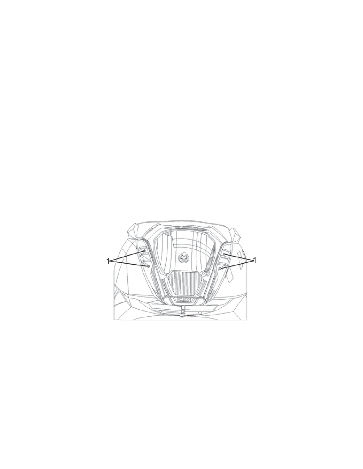
1. Remove the right front fairing. Refer to Front Fairing Replacement in Body Front End.
2. Remove the headlamp bolts (1).
Version 1.0/May 2011
VECTRIX, LLC
Page 53
VECTRIX VX-2 SERVICE MANUAL
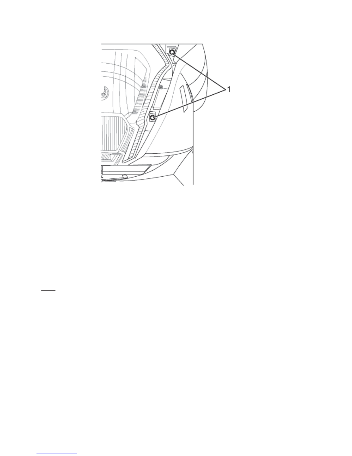
3. Pull the headlamp off the front sub-frame enough to remove the lamp harness connectors.
4. Remove the lower marker lamp bulb connector.
5. Disconnect Headlamp Assembly connectors and replace with new Headlamp Assembly.
6. Connect the headlamp and lower marker lamp connectors.
7. Install the headlamp assembly onto the left front fairing and install bolts (1). Tighten
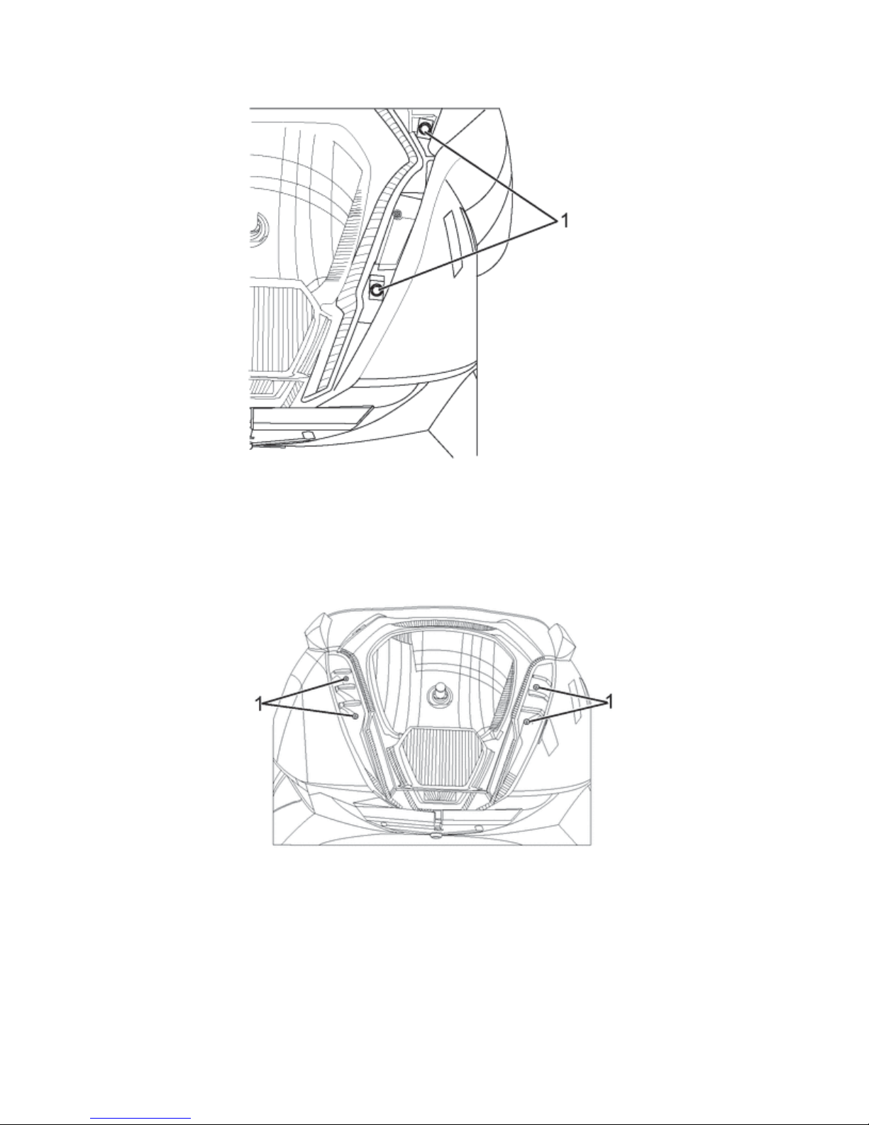
Headlamp bolts to 2 Nm (18 lb in)
Note
: Refer to Fastener Notice in General Information.
Version 1.0/May 2011
VECTRIX, LLC
Page 54
VECTRIX VX-2 SERVICE MANUAL
9. If the headlamp assembly was replaced aim the headlamp. Refer to Headlamp Adjustment
Procedure.
Version 1.0/May 2011
VECTRIX, LLC
Page 55

VECTRIX VX-2 SERVICE MANUAL
SECTION C-9:
FRONT TURN INDICATOR ASSEMBLY
(Both Left and Right)
Preparations:
Disassemble Front Fairing see Section B-1
Remove all cable strips
Remove connector (2-pins) of the Turn Indicator Light
Remark:
Lights
Unscrew the Nut from the inside with a wrench
Remove entire Front Turn Signal Assembly and pull cord
through the hole.
Replace entire Front Turn Signal Assembly
Procedure is the same for both Turn Indicator
Remark:
the whole assembly.
Assemble all parts in the opposite directions
Test function of Front Turn Indicator Light Assembly
Since the assembly is LED, you must replace
Version 1.0/May 2011
VECTRIX, LLC
Page 56

VECTRIX VX-2 SERVICE MANUAL
SECTION C-10:
SIDE STAND SWITCH
Preparations:
Disassemble Center Step-Through Cover see Section B-6
Remove the connector inside of the electronic box
under the seat
Unscrew the bolt by 8mm open end wrench
Assemble all parts in the opposite directions
Test function of Side Stand Switch
Version 1.0/May 2011
VECTRIX, LLC
Page 57

VECTRIX VX-2 SERVICE MANUAL
SECTION C-11:
REAR TAIL LIGHT ASSEMBLY
Preparations:
Disassemble Left and Right Rear Body Panels see Section B-10
Remove all cable strips
Open 3-pin connector
Unscrew the two side screws and one middle screw with
Phillips screwdriver
Pull out the Tail Light assembly backwards and disconnect
plug.
Replace entire Tail Light Assembly
Note
: Since the Rear Tail Light is LED, you must replace
the whole assembly.
Assemble all parts in the other direction
Test function of Brake and
Position lights
Version 1.0/May 2011
VECTRIX, LLC
Page 58

VECTRIX VX-2 SERVICE MANUAL
SECTION C-12:
LICENSE PLATE LIGHT
Preparations:
Disassemble Rear Fender see Section B-11
Remove all cable strips
Open 2-pin connector
Unscrew the two Phillips screws with a Phillips screwdriver
PH2
Pull out the License Plate Light assembly
License Plate Bulb
Unscrew the two Phillips screws with a Phillips screwdriver
PH2
Remove plastic cover
Pull out the defect bulb
Remark:
bulb with the fingers, use a tissue
Don’t touch the glass body of the new
Assemble all parts in the other direction
Test function of license light
Version 1.0/May 2011
VECTRIX, LLC
Page 59

VECTRIX VX-2 SERVICE MANUAL
SECTION C-13:
REAR TURN INDICATOR LIGHT ASSEMBLY
Preparations:
Disassemble Rear Fender see Section B-11
Remove all cable strips
Open 2-pin connector
Cut the cable of the Rear Indicator Light assembly
Remark:
the plastic
Remove the nut with an open wrench 14mm
Pull out the Rear Turn Indicator assembly
Remark:
Assemble all parts in the other direction
Test functions of Rear Light Assembly
Connector has to be cut because the
connector doesn’t fit through the hole of
Slightly push in the pins into the new
connector. Be sure of the right position.
Refer to the old connector
Version 1.0/May 2011
VECTRIX, LLC
Page 60

VECTRIX VX-2 SERVICE MANUAL
Rear Turn Indicator Assembly
No disassembly necessary
Replace entire Rear Turn Indicator Assembly
: Since the Rear Turn Indicator Assembly is LED,
Note
you must replace the entire assembly.
Assemble all parts in the other directions
Test functions of Rear Turn Indicator Assembly
Version 1.0/May 2011
VECTRIX, LLC
Page 61

VECTRIX VX-2 SERVICE MANUAL
SECTION C-14:
SEVCON MOTOR CONTROLLER
Preparations:
Disassemble Seat see Section B-8
Disassemble Left and Right Rear Body Panels see Section B-10
Open the seat and remove Cover of electronic box by
using
- Phillips screwdriver (old version)
- Special secure Torx screwdriver (new version)
Turn Key Switch in “ON” Position
Unplug blue Battery Main Connector
Turn Key Switch in “OFF” Position
Disconnect Positive Terminals first and remove Main Fuse
(1)
Then disconnect remaining (Negative) cables and wiring
harness
1
Version 1.0/May 2011
VECTRIX, LLC
Page 62
VECTRIX VX-2 SERVICE MANUAL
Unscrew the four Phillips bolts at the base of the Motor
Controller to remove the Motor Controller
In
stall new Motor Controller and re-secure with four
P
hillips bolts
Reconnect Ne
Then replace Main Fuse and Positive Cables next
Reconnect the blue Battery Connection Cable
est functions of Sevcon Motor Controller T
gative Cables and Wiring Harness first
Version 1.0/May 2011
VECTRIX, LLC
Page 63

VECTRIX VX-2 SERVICE MANUAL
SECTION C-15:
MOTOR
Preparations:
Disassemble Side Cover see Section B-15
Disassemble Rear Brake see Section B-16
: This is the same procedure to replace the Rear Brake Rotor
Note
Open the seat and remove Cover of electronic box by
using
- Phillips screwdriver (old version)
- Special secure Torx screwdriver (new version)
Turn Key Switch in “ON” Position
Unplug blue Battery Main Connector
Turn Key Switch in “OFF” Position
Disconnect Positive Terminals first and remove Main Fuse
(1)
1
Disconnect Remaining (Negative) Cables and Wiring
Harness
Version 1.0/May 2011
VECTRIX, LLC
Page 64
VECTRIX VX-2 SERVICE MANUAL
Unscrew the four Phillips bolts at the base of the Motor
Controller to remove the Motor Controller
Unscrew the hexagonal nut by using a 8mm open wrench
nd remove the cable clamp
a
Pull out the motor cable slightly of the electronic box
Remark
It is not necessary to remove the parts as it can be seen
on the picture
Unscrew the motor nut with a special open wrench tool or
e Vectrix EM-90400 Speciath
Take out the motor in the direction of the arrow on the
icture. p
:
l spanner socket
Versio
n 1.0/May 2011
VECTRIX, LLC
Page 65

VECTRIX VX-2 SERVICE MANUAL
All parts of removed motor
Assemble all parts in the other direction
est function of Motor T
Version 1.0/May 2011
VECTRIX, LLC
Page 66

VECTRIX VX-2 SERVICE MANUAL
SECTION C-16:
BATTERY
Preparations:
Disassemble Blue Battery Cable Connection see Section C-15
: Photos in this section show the Sevcon Motor Controller Housing removed which makes
Note
the procedure easier to complete but is not necessary if only the Step-Through panel is
removed.
Unscrew the hexagon bolts from Battery #1 und #3
Lift up battery #2 and remove it
Remark
Batteries are fixed to the battery case with strong velcro.
Move the batteries sideways to loosen them from the
velcro before remove.
Lift up battery #3 and remove it
:
Version 1.0/May 2011
VECTRIX, LLC
Page 67

VECTRIX VX-2 SERVICE MANUAL
Lift up battery #1 and remove it
Lift up battery #4 and remove it
Empty battery case for 60AH
Assemble all parts in the other direction
After assembling:
- Measure the voltage of each battery. It should be higher than 12.0 VDC.
- Charge the battery before
use!
Version 1.0/May 2011
VECTRIX, LLC
Page 68

VECTRIX VX-2 SERVICE MANUAL
SECTION C-17:
BATTERY CHARGER
Preparations:
Open Under Seat Storage
Put Key into key hole on the side of the VX-2 to open
Under Seat Storage Area.
Turn Key to open Under Seat Storage Area
Version 1.0/May 2011
VECTRIX, LLC
Page 69

VECTRIX VX-2 SERVICE MANUAL
Remove Battery Charger from Under Seat Storage Area
Plug blue Battery Charger male connector cord into onboard blue Battery Charger female connection.
Plug Battery Charger AC connector into a AC main.
Version 1.0/May 2011
VECTRIX, LLC
Page 70

VECTRIX VX-2 SERVICE MANUAL
Turn on Battery Charger Unit power switch.
Recharge until Battery Charger Output LED reaches 100%
(Yellow).
Note
: Recharge process can be discontinued and re-
started at any time during the charge cycle
Version 1.0/May 2011
VECTRIX, LLC
Page 71

VECTRIX VX-2 SERVICE MANUAL
SECTION D-1:
MIRRORS ADJUSTMENT
If mirrors are not tightened, remove Left and Right mirrors
(refer to Section C, Section C-1) and tighten the nut by
using a 14mm open wrench
Version 1.0/May 2011
VECTRIX, LLC
Page 72

VECTRIX VX-2 SERVICE MANUAL
Coarse adjustment:
Turn the mirror in the correct position by using the mirror
housing
The movement should be done with some force, otherwise
proceed as figure before
Version 1.0/May 2011
VECTRIX, LLC
Page 73

VECTRIX VX-2 SERVICE MANUAL
Fine adjustment:
Move the mirror in the correct position
Version 1.0/May 2011
VECTRIX, LLC
Page 74

VECTRIX VX-2 SERVICE MANUAL
SECTION D-2:
HEADLAMP/POSITION LIGHT ADJUSTMENT
Headlamp Aiming
S-ST-100000
Properly aim the headlamp for maximum road illumination and safety. With halogen headlamps,
proper aiming is very important. The increased range and power of these lamps make even the
slightest variations from the recommended aiming hazardous to approaching motorists.
Observe the following conditions when you inspect or adjust the headlamp aim:
• The scooter is on a level surface.
• The tires are uniformly inflated to the specified pressure.
• One person is sitting on the driver's seat.
• The scooter is in the vertical position.
• Clean the headlamp before aiming.
• Follow your state's requirements for headlamp aiming.
Headlamp Aiming Location
• The aiming area should be darkened and large enough to allow for the scooter and an
additional 10 m (33 ft), measured from the face of the headlamp to the front of the screen.
• The floor on which the vehicle rests must be parallel with the bottom of the screen. If the floor
is not level, compensate accordingly.
Version 1.0/May 2011
VECTRIX, LLC
Page 75
VECTRIX VX-2 SERVICE MANUAL
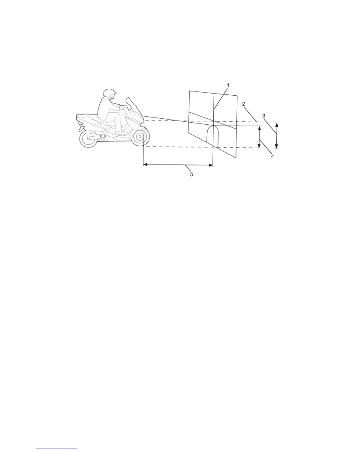
Headlamp Aiming Procedure
1. Position the scooter square with the screen, with the headlamp directly over the 10 m (33 ft)
reference line (5).
2. Ensure that the vehicle is on a level surface.
3. Draw a horizontal reference line (2) that is in the center of the headlamp.
4. Draw a vertical reference line (1) that is in line with the scooter axis.
5. With the headlamp low beam on the height spot (4) should 9/10th of the headlamp center line
(3).
Adjusting the headlamp
1. To adjust the light beam up and down turn the right lower side adjustment screw. Clockwise
to raise the beam and counterclockwise to lower the beam.
2. To adjust the light beam side-to-side turn the upper left adjustment screw. Clockwise to move
the beam to the right and counterclockwise to move the beam to the left.
Version 1.0/May 2011
VECTRIX, LLC
Page 76

VECTRIX VX-2 SERVICE MANUAL
SECTION E-1:
INDICATION ON SPEEDOMETER DISPLAY & CONTROLLER LED
Indication on LCD Controller
LED
Accelerator turn
at power up
Error
Accelerator Volt
Stop scooter
Battery empty!
Error
Overcurrent
Error
Hall sensor
Scooter
Disabled
Error
Voltage too high
Error
High temperature
Stop scooter
High temperature
Low Battery
Recharge!
Error
Sidestand out
System
Error 01
1 Accelerator is not in
2 Accelerator voltage
3 Battery voltage is
4 Controller
5 Hall sensor
6 This messages
7 Battery voltage is
9 Temperature of the
10 Temperature of the
11 Battery voltage is
6 Side stand switch is
Reason Solution
Release accelerator or turn power
zero position
too high
under 42V
permanently
defect
Malfunction of the
motor
comes after Stop
scooter
over 63V
controller is >85
controller is >110
under 42V
> 15 seconds
active
Memory of
speedometer defect
“OFF” and then to “ON” or proceed to
the Accelerator troubleshooting
diagram
Release accelerator or turn power
“OFF” and then to “ON” or proceed to
the Accelerator troubleshooting
diagram
Charge the Battery
Exchange controller and check motor
for short winding against housing
Proceed to Hall Sensor check
Section 4 of Section E
Solve malfunction before this
message
Use the scooter carefully until
message is over, if not, check if the
real voltage of the battery is lower
than 63V and setting of controller.
Or exchange Controller.
Wait until temperature goes down
o
C
under 85 oC.
Or exchange Controller
Wait until temperature goes down
o
C
under 110 oC.
Or exchange Controller
Charge the Battery
Check correct function of side stand
switch.
Exchange Side Stand Switch or
controller
Exchange Speedometer if message is
still there.
The LED on the controller flashes if a malfunction is active.
Example
: LED flash 6 times with 1 Hz, LED off for 2 sec. and starts again.
This means: Disable function active
Version 1.0/May 2011
VECTRIX, LLC
Page 77

VECTRIX VX-2 SERVICE MANUAL
SECTION E-2:
MALFUNCTIONS
- No Top Speed
- Check setting of the controller
- Check correct function of the accelerator, exchange if needed
- No function and no indication on Speedometer
- Check Fuse 1 (15A) of the converter
- Check voltage on Controller power in line (red and black thick wire) should be
higher than 36 V.
- Converter broken
- Full function but no indication on Speedometer
- Check connection of the speedometer
- Speedometer broken
- No indication of the energ y bar on Speedometer
- Check Voltage of the battery
- Check Voltage on Pin 1 of the speedometer connector. Should be the battery
Voltage
- Speedometer or controller broken or wire between controller and speedometer
- No indication of the consumption bar on Speedometer
- Check Voltage of the battery
- Check Voltage on pin 1 of the Speedometer connector. Should be the battery
Voltage
- Speedometer or Controller broken or wire between Controller and Speedometer
- No change of battery voltage and mph/kph on Speedometer
- Check correct function of MODE switch
- Mode switch or Speedometer broken
- No indication of speed on Speedometer but motor running is okay
- Check if the Voltage on Pin 5 of the speedometer connector. Should change if
Motor is turned by hand.
Speedometer or Controller broken or wire between Controller and Speedometer
Version 1.0/May 2011
VECTRIX, LLC
Page 78

VECTRIX VX-2 SERVICE MANUAL
SECTION E-3:
CHECK OF CHARGER FUNCTION
1. Normal function
If the Charger is connected and the indication led on the charger is at 60%, turn on the
scooter and the battery voltage indication of the speedometer should show 59.5 V +
1.0 V.
During the charging process at 60%, the current should be 10.0 A +
clamp ampere meter on the brown wire close to the charger DC-plug.
If not, check the voltage with a digital voltmeter on the Controller power in line (red and
black thick wire). The value should be 59.5 V +
exchange Charger.
2. Charger didn’t start
Using a Digital Multi meter:
- Open the cover seat
- Measure on the charger connector of the scooter if the voltage is like the battery voltage
indication of the speedometer. If the voltage is zero, check the fuse #2 (30A) of the
converter or the connection cable. If the voltage is lower than 33 V check the voltage of
each battery and exchange the battery which is lower than 10.0V.
- Exchange Charger
1.0 V. If yes, exchange speedometer, if not,
0.8 A, measured with a
Version 1.0/May 2011
VECTRIX, LLC
Page 79

VECTRIX VX-2 SERVICE MANUAL
SECTION F-1:
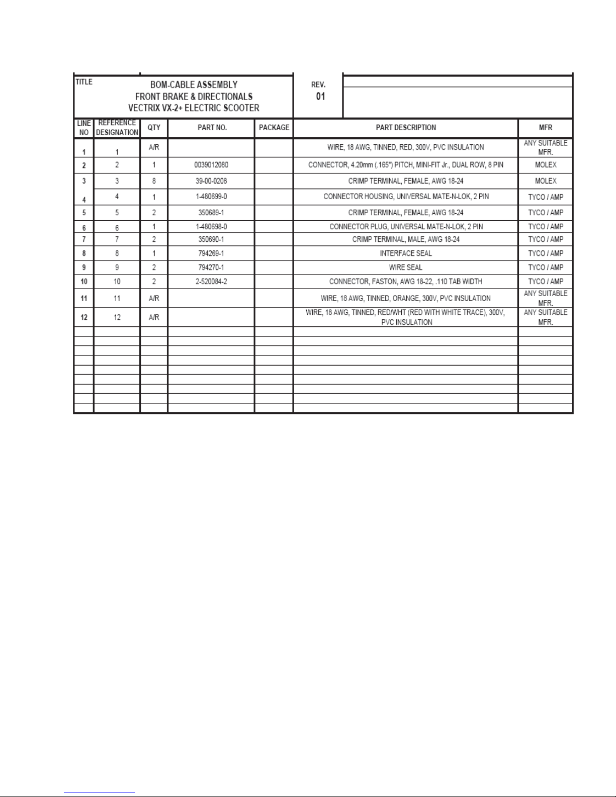
CABLE ASSEMBLY-FRONT BRAKE/INDICATORS + BOM
Version 1.0/May 2011
VECTRIX, LLC
Page 80
VECTRIX VX-2 SERVICE MANUAL
Version 1.0/May 2011
VECTRIX, LLC
Page 81
VECTRIX VX-2 SERVICE MANUAL
SECTION F-2:
CABLE ASSEMBLY-FRONT HEADLAMP/HORN + BOM
Version 1.0/May 2011
VECTRIX, LLC
Page 82

VECTRIX VX-2 SERVICE MANUAL
Version 1.0/May 2011
VECTRIX, LLC
Page 83
VECTRIX VX-2 SERVICE MANUAL
Version 1.0/May 2011
VECTRIX, LLC
Page 84
VECTRIX VX-2 SERVICE MANUAL
SECTION F-3:
CABLE ASSEMBLY-REAR BRAKE/INDICATORS/TAIL LIGHT/BATTERY/SIDE
STAND + BOM
Version 1.0/May 2011
VECTRIX, LLC
Page 85
VECTRIX VX-2 SERVICE MANUAL
Version 1.0/May 2011
VECTRIX, LLC
Page 86

VECTRIX VX-2 SERVICE MANUAL
SECTION F-4:
TORQUE LIST FOR BOLTS/NUTS
Description Force
Front axle self locking, nut 65 NM
Front brake housing on front shock , bolt 30 NM
Rear brake housing on rear fork, bolt 25 NM
Motor axle, nut 80 NM
Front shock, bolt 70 NM
Brake disc on front rim, bolt 25 NM
Brake disc on motor, bolt 15 NM
Ring on motor, bolt 15 NM
Handle bar, nut 50 NM
Rear fork, left and right nut 80 NM
Front fork, top nut, 32mm 60 NM
Rear shock, top bolt 45 NM
Rear shock, bottom nut 40 NM
Battery, bolt 25 NM
All plastic parts 16 kgf.cm
Version 1.0/May 2011
VECTRIX, LLC
Page 87

VECTRIX VX-2 SERVICE MANUAL
SECTION G-1:
UNPACKING INSTRUCTIONS
Version 1.0/May 2011
VECTRIX, LLC
Page 88

VECTRIX VX-2 SERVICE MANUAL
Version 1.0/May 2011
VECTRIX, LLC
Page 89

VECTRIX VX-2 SERVICE MANUAL
Version 1.0/May 2011
VECTRIX, LLC
Page 90

VECTRIX VX-2 SERVICE MANUAL
Version 1.0/May 2011
VECTRIX, LLC
Page 91

VECTRIX VX-2 SERVICE MANUAL
Version 1.0/May 2011
VECTRIX, LLC
Page 92

VECTRIX VX-2 SERVICE MANUAL
Version 1.0/May 2011
VECTRIX, LLC
Page 93

VECTRIX VX-2 SERVICE MANUAL
SECTION G-2:
PREP INSTRUCTIONS
Version 1.0/May 2011
VECTRIX, LLC
Page 94

VECTRIX VX-2 SERVICE MANUAL
Version 1.0/May 2011
VECTRIX, LLC
Page 95

VECTRIX VX-2 SERVICE MANUAL
Version 1.0/May 2011
VECTRIX, LLC
Page 96

VECTRIX VX-2 SERVICE MANUAL
Version 1.0/May 2011
VECTRIX, LLC
Page 97

VECTRIX VX-2 SERVICE MANUAL
Version 1.0/May 2011
VECTRIX, LLC
Page 98

VECTRIX VX-2 SERVICE MANUAL
Version 1.0/May 2011
VECTRIX, LLC
Page 99

VECTRIX VX-2 SERVICE MANUAL
Version 1.0/May 2011
VECTRIX, LLC
 Loading...