

Vectorworks Sail Blade F16 Owner's Manual

Revision Date: 2006-03-17
Owner’s Manual
Copyright © 2006 - Vectorworks Sail - 805 Marina Road - Titusville, FL 32796 USA - 321-269-8444
Page 1

Vectorworks Sail
Statement
This manual covers the basic assembly of the
above listed models. Before starting assembly,
familiarize your self with the contents of the
containers and the steps in this manual. There
are variations between models and may be some
minor variations based on model year and
options, be sure to follow the appropriate
Page 2
Vectorworks Sail
Blade F16
procedures where applicable.

Table of Contents
1.0 Contents
2.0 Hull Assembly
3.0 Trampoline Assembly
4.0 Trap Bungee
5.0 Mast Rotation
6.0 Mast Assembly
6.1 Spreaders
6.2 Diamond Wires
6.3 Main Halyard
6.4 Spin Halyard
6.5 Standing Rigging
6.6 Pelican Striker Assembly
7.0 Stepping the Mast
8.0 Rudders
8.1 Surf System
8.2 Rudder Alignment
9.0 Spin Pole
10.0 Jib Sheet System
10.1 Jib Rotation Limiter
10.2 Jib Sheet
11.0 Boom
12.0 Mast Rotation - Mast connection
13.0 Mainsail
13.1 External Downhaul
14.0 Raising the Mainsail
15.0 Lowering the Mainsail
16.0 Mainsheet
17.0 Downhaul
18.0 Outhaul
19.0 Jib
20.0 Spinnaker
20.1 Halyard Run
20.2 Attaching the Spin
21.0 Spin Sheet
22.0 Sailing and Beaching
23.0 Righting After a Capsize
24.0 Trailering and Storage
25.0 Design Category
26.0 Maintenance
27.0 Warranty
Page 3
1.0 - Contents
***** Need list of contents and picture of them
***** List of required tools
***** List of required Supplies (silicone…)
Picture of all the parts
with descriptions
Some parts may vary slightly from what is pictured.
The exact contents may differ depending on model and options
Fig 1.A
Page 4
2.0 – Hull Assembly
After unpacking the hulls, verifying the contents and verifying they did not receive any
damage in transport, find a flat soft area to begin the assembly of your boat. Place the
hulls on carpet, foam blocks, or other smooth item where they can be moved without
damaging the surface. First check the width spacing while trying to keep them as close
to the same fore and aft setting as possible. The centerline width of the hulls should be
7’. Check at the bow and stern. Once this is set, measure the diagonals of the hulls to
make sure they are not skewed. This should be within 1/8” of each other. Adjust the
fore and aft position of the hulls as required, and recheck the width measurement to
ensure it has not changed. This may take several iterations. It is very important that
this be done very carefully as severe damage could occur to the beams or hulls if they
are tightened with the hulls out of alignment. (Figure 2.A).
Warning
Warning: Diagonal measurements need to be within 1/8” of each other or
Once the hulls are set, remove the bolts from the cross bars and set on the hulls. Dry
fit the bolts to ensure everything will fit smoothly. The hulls were pre-assembled in the
factory, so if they are aligned properly, the bolts should slide smoothly into the hulls.
After you are confident of the fit, lift the beams and place a bead of silicone around the
bolt holes and another small amount around the perimeter of the beam landings. This
will seal the holes to help prevent minor leaking of the boat. Now install the bolts and
tighten to 18 to 20 ft/lbs with a torque wrench, always making sure the hulls have not
shifted. Note these bolts need to be kept tight. Always check them before sailing the
boat. They will need tightening the first few times the boat is sailed. They should settle
in after a few sails.
Picture of silicone
Picture of Hulls on blocks showing
dimensions
Figure 2.A
damage to the beams and/or hulls could occur.
Picture of mounted cross
placement
Fig 2.B
Fig 2.C
bar
Page 5
3.0 – Trampoline Assembly
Fig 3.A
Fig 3.B
Fig 3.C
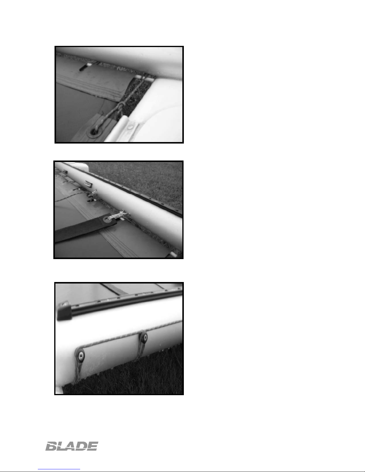
After the cross bars are adequately
tightened, now it is time to string the
trampoline. Find the edge on the tramp with
the larger bolt rope, and slide it into the
groove in the front cross bar with the
zippered pocket facing up. (Figure 3.A)
Now feed the 2 smaller bolt ropes along the
tracks located on the hulls. Note this is a
diagonally cut tramp and you will need to
pull them down the tracks at the same time,
this will either take patience, or an additional
person. Once the tramp bolt ropes are
pulled, slide the 6’ fiberglass rod into the
pocket located on the aft end of the tramp,
and center. (Figure 3.B)
Find the 5/32” x 20’ long line labeled
“Tramp Lacing” and tie one end to either
of the grommets located in the aft
outside corner of the tramp. Pull the line
snug and bring back under the rear cross
bar and wrap over the first of the tramp
lacing buttons located on the aft side of
the cross bar. Bring the line forward and
wrap over the exposed end of the
fiberglass rod, and then back to the first
lacing button again. Pull the line over
the top of the first button and string over
the top of the second. Once over the top
of the second, go back under the cross
bar and wrap around the fiberglass rod at
the first notch, bringing it back to the
second button, over this button then to
the third. (Figure 3.C)
Continue across the entire tramp
finishing the opposite side in a mirror of
the start. Note the tramp will be loose
and will take several tightenings to
become fully taught. Once the back is
laced, remove the 1/8” x 30” lines and tie
the foot straps to the saddles provided
on the rear cross bar.
Page 6
4.0 – Trap Bungee
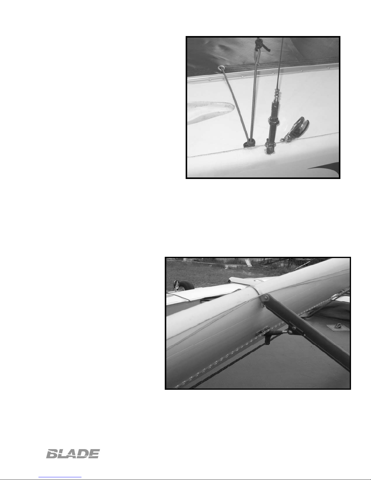
The forward trap bungee has already
been installed in the forward cross bar.
Remove the bungee from the
packaging and slide the bungee
through the black grommet located on
the hull near the side stay attachment.
Then feed the line through the nearest
tramp grommet, under the tramp and
back up the opposite side. Fix the
ends with the ball stops and hog rings
in identical fashion to the forward set
up. (Figure 4.A)
5.0 – Mast Rotation
Find the 5/32” line labeled “Mast
Rotation”. Feed this line through the
cleat located on the hull just aft of the
front cross bar, and then under the
Fig 4.A
tramp. Bring the line back up through
the tramp at the grommet located in the center of the tramp just aft of the storage
pocket. Run this line through the turning block provided and back through the center
grommet, under the tramp and back up through the cleat on the opposite hull. Note:
the turning block will be attached to the line run through the mast rotation arm on the
mast after the mast is stepped to control rotation.
6.0 – Mast Assembly
6.1 - Spreaders: Attach the
spreader arms to the fittings
located approximately ½ way up
the mast. Use the barrel nut to
adjust the rake of the spreaders
such that they are equally
positioned and a straight edge
placed between them will
provide a gap of at least 1 ½”
measured between it and the
mast. Adjust the extensions
and rake of the spreaders so
that they measure
approximately 27 ½” tip to tip,
and 1 ½” of rake. Note: these
measurements are made from
the location of the wire, and not
the end of the retention clips on
the spreaders. Make sure both are set at the same angle, as failure to do so may put
a permanent twist in the mast.
Fig 6.A
Page 7

6.2 - Diamond wires: To install the
diamond wires, first place a bead of
silicone in the holes located on the
mast sides above the spreaders.
When wet, place the ball-T end of the
diamond wires in the hole, and bring
the threaded end down to the mast
base. Place the threaded end of the
diamond wire through the holes on the
side of the mast base, putting one of
the jam nuts on each side of the base
plate (2 per wire) It is very important
the adjusting end is completely
lubricated with anti-seize, oil or other
suitable lubricant, as stainless will cold
weld itself if the nuts are tightened
Fig 6.B
under load. Once the threads have
been started, pull the diamond wire onto the spreader bars, as if you were stringing a
crossbow. The wires can then be tightened to the proper setting. A good starting point
will be at least 1 ¼ - 1 ½” of pre-bend as measured with a string line from the mast
base to the sail hook. Note it is best to tighten the wires when they are not under load
to prevent seizing. This may take several iterations to get the proper tension and
ensure that the mast is straight. Once set, tighten the jam nut located on the top of the
mast base, to ensure the wire do not loosen while sailing. These setting are a starting
point, and you will need to adjust them to fit your own sail, weight and sailing
conditions. Always ensure diamond wires have adequate tension. If you notice
you diamond wires loose at any time during sailing, stop and tighten them. Sailing with
loose diamond wires can lead to mast failure or collapse.
Warning
Warning: Always tape spilt rings to prevent them from coming loose during sailing.
Sailing with loose diamond wires can lead to mast failure or collapse.
6.3 - Main Halyard: Attach the main halyard
line to the main sail hook as shown. Run the
opposite end of the line up the exterior of the
mast and through the pulley located on the top
of the mast and then back down the inside of
the sail track. The end will then exit through
the turning pulley located just above the mast
base.
Page 8
Fig 6.C
 Loading...