

Page 1

Getting Started with
Vectorworks® Spotlight 2010
Page 2

Vectorworks Spotlight 2010 Getting Started Guide
Klad
Kevin Lee Allen Design (KLAD)
Kevin Lee Allen
56 Woodlawn Avenue
Clifton, NJ 07013
973.744.6352
klad@klad.com
© 2009 Nemetschek North America, Inc.
All rights reserved. No part of this book may be reproduced or transmitted in any form by any means, electronic or mechanical,
including photocopying, recording, faxing, emailing, posting online or by any information storage and retrieval system, without prior
written permission of the publisher. Published in the U.S.A.
Vectorworks is a registered trademark of Nemetschek North America, Inc. in the U.S. and other countries. Windows is a registered
trademark of Microsoft Corporation in the U.S. and other countries.Macintosh is a trademark of Apple Computer, Inc., registered in the
U.S. and other countries. Adobe, Acrobat and Reader are registered trademarks of Adobe Systems in the U.S. and other countries.
The information in this book is distributed on an “as is” basis, without warranty. While every precaution has been taken in the
preparation of this book, neither the author nor Nemetschek North America shall have any liability to any person or entity with respect
to any loss or damage caused or alleged to be caused directly or indirectly by the information contained in this book or by the
computer software described in it.
For more Vectorworks training information, or to purchase more copies of this book, please visit
www.Vectorworks.net/training or call us at (410) 290-5114.
2 Vectorworks 2010 Products
Page 3

Vectorworks Spotlight 2010 Getting Started Guide
Table of Contents
Introduction .............................................................................................................................................................. 7
How to Use this Manual .......................................................................................................................................... 8
Getting Help ............................................................................................................................................................. 9
The Spotlight Workspace ......................................................................................................................................11
Creating and Editing Workspaces ...................................................................................................................................................... 12
Creating a Template .............................................................................................................................................. 15
Organizing the Drawing ........................................................................................................................................ 17
Working Planes ................................................................................................................................................................................. 19
Locus Points ...................................................................................................................................................................................... 19
Rotated Views. .................................................................................................................................................................................. 19
Layer Plane and Screen Plane .......................................................................................................................................................... 20
Understanding Symbols ....................................................................................................................................... 21
Understanding Symbols .................................................................................................................................................................... 21
Available Resources .......................................................................................................................................................................... 21
Creating Symbols .............................................................................................................................................................................. 21
Creating Image Props ....................................................................................................................................................................... 23
Symbol Types .................................................................................................................................................................................... 26
File Referencing ................................................................................................................................................................................ 27
Primitive Drawing .................................................................................................................................................. 29
Other 2D Shape Tools ....................................................................................................................................................................... 34
Oval ................................................................................................................................................................................................... 34
Regular Polygon ................................................................................................................................................................................ 34
Polygon and Polyline ......................................................................................................................................................................... 34
Offset ................................................................................................................................................................................................. 35
Fillet and Chamfer ............................................................................................................................................................................. 36
Rotate ................................................................................................................................................................................................ 36
Mirror ................................................................................................................................................................................................. 36
Drawing with Lines and Making Objects ........................................................................................................................................... 36
Vectorworks 2010 Products 3
Page 4

Vectorworks Spotlight 2010 Getting Started Guide
Duplicate ........................................................................................................................................................................................... 37
Convert to Polygon and Re-Shaping ................................................................................................................................................. 38
Exercise ............................................................................................................................................................................................. 38
2D – 3D Drawing & Modeling ................................................................................................................................ 39
Sweep ............................................................................................................................................................................................... 39
Extrude Along Path ............................................................................................................................................................................ 42
Chain Extrude .................................................................................................................................................................................... 42
Multiple Extrude ................................................................................................................................................................................. 43
Editing 3D Shapes ............................................................................................................................................................................. 43
Exercise ............................................................................................................................................................................................. 43
3D Modeling ...................................................................................................................................................................................... 44
Manipulating Solids ........................................................................................................................................................................... 44
3D Primitives ..................................................................................................................................................................................... 44
Project — The Lighthouse ................................................................................................................................................................. 45
Using the Wall Tools .............................................................................................................................................. 47
Wall Tool ............................................................................................................................................................................................ 48
Floors ................................................................................................................................................................................................ 48
Door and Window Tools .................................................................................................................................................................... 48
Curtain Tool ....................................................................................................................................................................................... 49
Create Seating Layout ....................................................................................................................................................................... 50
Curved Wall Tool ............................................................................................................................................................................... 50
Wall Sculpting .................................................................................................................................................................................... 51
Column Tool ...................................................................................................................................................................................... 52
Stair Tools .......................................................................................................................................................................................... 53
Roof Tools ......................................................................................................................................................................................... 55
Drawing a Light Plot .............................................................................................................................................. 57
Label Legends ................................................................................................................................................................................... 57
Focus Point Objects .......................................................................................................................................................................... 58
Lighting Positions .............................................................................................................................................................................. 59
Truss.................................................................................................................................................................................................. 60
Creating Lighting Positions ................................................................................................................................................................ 60
Inserting Instruments ......................................................................................................................................................................... 60
Coloring your Lights .......................................................................................................................................................................... 61
Editing Lights ..................................................................................................................................................................................... 61
4 Vectorworks 2010 Products
Page 5

Vectorworks Spotlight 2010 Getting Started Guide
Adding Accessories ........................................................................................................................................................................... 63
Adding Gobos .................................................................................................................................................................................... 63
Vertical Lighting Positions ................................................................................................................................................................. 64
Shutter Cuts for Visualization ............................................................................................................................................................ 64
Projection/Monitor Tools .................................................................................................................................................................... 65
Photometrics/PhotoGrid .................................................................................................................................................................... 65
Scripting ............................................................................................................................................................................................ 66
Creating Custom Lighting Symbols ................................................................................................................................................... 67
Create Plot and Model View .............................................................................................................................................................. 67
Visualizing your Design ........................................................................................................................................ 71
Rendering Modes .............................................................................................................................................................................. 72
Layer Backgrounds ........................................................................................................................................................................... 74
Exercise ............................................................................................................................................................................................. 76
Textures ............................................................................................................................................................................................. 77
Creating Textures .............................................................................................................................................................................. 77
Assigning Textures ............................................................................................................................................................................ 80
Textures and Walls ............................................................................................................................................................................ 80
Textures in the OIP ............................................................................................................................................................................ 80
Mapping ............................................................................................................................................................................................. 81
Attribute Mapping Tool ....................................................................................................................................................................... 81
Decals ............................................................................................................................................................................................... 81
Camera Tool ...................................................................................................................................................................................... 82
Rendering a simple scene ................................................................................................................................................................. 83
Exercise ............................................................................................................................................................................................. 83
Lighting in the 3D World. ...................................................................................................................................... 85
View Menu Options. .......................................................................................................................................................................... 85
Directional Light Mode ....................................................................................................................................................................... 86
Spot Light .......................................................................................................................................................................................... 86
Point Light ......................................................................................................................................................................................... 87
IES Files and Custom Lights ............................................................................................................................................................. 87
Line Lights and Area Lights ............................................................................................................................................................... 87
Lit Fog Option .................................................................................................................................................................................... 87
Exercise ............................................................................................................................................................................................. 88
Vectorworks 2010 Products 5
Page 6

Vectorworks Spotlight 2010 Getting Started Guide
Presenting your Drawings .................................................................................................................................... 89
Viewports and Sheet Layers ............................................................................................................................................................. 89
Key to Instrumentation ...................................................................................................................................................................... 91
Dimensions and The Annotation Space ............................................................................................................................................ 92
Drawing Border Tool .......................................................................................................................................................................... 93
Custom Title Blocks ........................................................................................................................................................................... 93
Graphic Scale Tool ............................................................................................................................................................................ 94
Drawing Labels .................................................................................................................................................................................. 94
Viewport Cropping ............................................................................................................................................................................. 95
Section Viewports .............................................................................................................................................................................. 95
Class Overrides ................................................................................................................................................................................. 96
Paperwork ......................................................................................................................................................................................... 96
NURBS .................................................................................................................................................................... 97
NURBS Tools (from the Toolset)........................................................................................................................................................ 97
NURBS Commands (from the 3D Power Pack) ................................................................................................................................ 97
Fillet or Chamfer Edge ...................................................................................................................................................................... 98
Protrusion Cutout .............................................................................................................................................................................. 99
Solid Addition/Loft Tool .................................................................................................................................................................... 101
Revolve with Rail ............................................................................................................................................................................ 102
Surface Thickening/Solid Shell Tool ................................................................................................................................................ 103
Conclusion ...................................................................................................................................................................................... 103
Exercise ........................................................................................................................................................................................... 103
Links ..................................................................................................................................................................... 104
Bio ........................................................................................................................................................................ 105
6 Vectorworks 2010 Products
Page 7

Vectorworks Spotlight 2010 Getting Started Guide
Introduction
This guide is not designed to make you an expert in Vectorworks, Spotlight or Renderworks. It is designed to teach the basics of
working with these software tools. This is one of many possible workows. Your own methods may vary slightly over time. This book
only begins to scrape the surface as to what can be done with Vectorworks Spotlight.
I work on a Macintosh computer; thus all of the screen shots here show the MacOS. Windows users will nd the same information in
the same places. It may look a bit different. From time to time, I have inserted information about keyboard shortcuts. Again, I generally
make reference to the Command Key. On a PC, that usually means the Control Key. There is a complete reference to these shortcuts
in the help les, complete with cross referencing the two OS.
This guide comes as a shorter introduction piece in printed form, and exists in a more thorough form on the accompanying DVD.
When I teach Vectorworks, I stress the architectural concept of Building Information Modeling (BIM). Simply put,this is working and
collaborating in the three-dimensional environment. On a more complex level, BIM allows 2D and 3D representations of objects
connected with data. On a collaborative level, this allows a set designer to provide a void and T
with structure, lighting designers to add instrumentation, sound designers to insert microphones or speakers and video designers to
add screens and gear. BIM in the performing arts allows for a truly collaborative space for the various partners to work and share
information across a series of referenced les.
As a professional, I work this way. I nd that this workow allows me to develop a project from beginning to end, collaborate effectively
and produce both presentational materials and construction documents that evolve with the design.
Working in the 3D space with dynamic links to presentations (sheet layers) keeps the entire project constantly update
echnical Directors to ll parts of that void
Using Metric Units with Exercises
All exercise data set les for this tutorial are set to use imperial units.
Vectorworks 2010 Products 7
Page 8

Vectorworks Spotlight 2010 Getting Started Guide
How to Use this Manual
Work through the guide. This is the house that Jack built. Each exercise or process, no matter how simple, leads to the next •
exercise. It helps to have the hands and the mind work through the simple steps before reaching more complex problems.
This manual covers a lot of ground quickly. Yet, you will see it still just skims the surface of a powerful application. Everything is •
here so that you can get up to speed with Vectorworks Spotlight quickly.
Alternate methods are shown for activating/using many tools, commands, and modes.
•
Use what works best for you.
Experiment with different tools and techniques.
•
Watch for SmartCursor cues, which appear as you hover your cursor over signicant drawing object geometry.•
To pan across the drawing at any time (even if a tool or command is active) hold down the Space Bar and drag the cursor. •
I do assume you are familiar with basic computer terms and basic theatrical concepts.•
Save early, save often.•
Establish a back-up ritual.•
Save-As frequently, so you can always access earlier ides and solutions.•
Use symbols, get to know and understand them early.•
Use the Vectorworks auto back-up in addition to your own back up plan.•
Most tools have options, selected in the Tool bar. See the illustration on page 13.•
Don’t be concerned if you do not understand this entire introduction, it will all be explained...•
8 Vectorworks 2010 Products
Page 9

Vectorworks Spotlight 2010 Getting Started Guide
Getting Help
Learning software is like learning how
to ride a bicycle. First: learn to fall. Fortunately, Nemetschek North America has made getting back up easy.
First let’s look at the Vectorworks help system. You can select Vectorworks Help from the Help menu, which will open the Help
application or select “What’s This?” which will change your cursor to an arrow with a question mark. You may then use this cursor to
select an object within Vectorworks and you will be sent to the appropriate location within the Vectorworks Help application.
The Vectorworks Help application is a robust depository of information that users are able to modify and adjust to their needs. Like
Vectorworks itself, the application can be automatically updated as information changes.
The Help Application Window is divided into two columns. The left column provides navigation and the right column information. If you
enter search criteria where it says “Enter text to search,” results will be displayed and ranked in the right column. Selecting a search
result will display the search topic.
Search results can be saved as Favorites by clicking on the star icon. Y
We all have trouble committing every detail of a program this complex to memory. It takes repeated use. At http://vectorworks.net it is
possible to access a number of additional learning and informational tools, including user forums, mailing lists, demonstration videos
and other guides (http://www.vectorworks.net/training/guides.php). The Vectorworks online community (http://www.vectorworks.net/
community/index.php) is dynamic and supportive. I strongly suggest membership in the user forums and e-mail lists.
ou may also add comments and other information.
Vectorworks 2010 Products 9
Page 10

Vectorworks Spotlight 2010 Getting Started Guide
There are specic lists and forums for theatre and Spotlight, but I would not neglect the general forums and lists. Many issues that arise
in Spotlight are familiar to the larger groups of users. Questions posed to the online community are often answered almost immediately.
Since Vectorworks is used widely internationally, it almost doesn’t matter when you are working; there are other people working around
the world.
You will nd links to the online community as well as RSS feeds in the favorites tab of the Help application. As you explore Vectorworks
online, you can add other links.
Reading online posts is a great way to learn the full capabilities of
Vectorworks. The new user may not immediately grasp all of the
topics, but eventually it will all make sense.
PDF manuals can be accessed from the Help table of contents.
Let’s take a look at what else comes with the application.
Some of the terms used here have not been dened as yet; we’ll get
to them, but it is important to have an early idea about what comes
with the application.
On a Mac, the Vectorworks directory should be in the Applications
folder on your hard drive. On a PC, this directory should be in the
Program Files folder.
The libraries are another important feature that will take time to
explore. The libraries are lled with symbols (pre drawn objects) that
can be used. Critically, the Objects-Entertainment directory contains
symbols for nearly all of the lighting instruments available. There are
also accessories, lighting positions, speaker symbols, and truss
symbols.
There are also libraries for textures (used for ‘painting’ scenic
elements and Gobo Textures).
Symbols are 2D and 3D combined, or ‘Hybrid’ objects, that can be
used repetitively and can have critical information attached to them
via a data record. We’ll discuss symbols throughout this guide.
10 Vectorworks 2010 Products
Page 11

Vectorworks Spotlight 2010 Getting Started Guide
The Spotlight Workspace
When rst opening the Vectorworks Spotlight application, if your screen doesn’t look like this, you either don’t have Spotlight or you’re
in the wrong workspace. Go to the Menu and select Tools>Workspaces> Spotlight.
On the left side of your screen you should see the Basic Tool Palette and the Tool Sets Palette which allow you to access additional
tools for particular jobs. The Attributes Palette and the Snapping Palette are also to the left. On the right you should see the Object
Information Palette (OIP), Navigation Palette, Visualization Palette and Resource Browser.
At the top of the active window, you will see the View bar and the Tool Bar. The Tool Bar displays different options available for each
tool selected from the Basic Tool Set or one of the task specic Tool Sets. The View bar allows ready access to a number of important
functions. View bar functions can be hidden and displayed from the drop-down list on the right of the View bar.We will cover most of the
View bar elsewhere, but from the left you will see forward and backward arrows; clicking on these will take you back and forth between
recent document views. Skip to the center right and you will see two magnifying glass icons that take you a view of either a selected
item or to a view of all items in the visible drawing (if nothing is selected). Command-6 on a Mac and Control-6 on a PC have the
same functionality.
Vectorworks 2010 Products 11
Page 12

Vectorworks Spotlight 2010 Getting Started Guide
There is a drop down menu for your view of the drawing. Typically, set to Top/Plan (Command-5) which is the 2D view from overhead.
Top is a 3D overhead view, and the others should all make logical sense. You can also access each of these views from your numeric
keypad with 5 being Plan, 2 being Front, etc.
The OIP (Object Information Palette) is a critical design control point; every object selected in Vectorworks can be manipulated via the
OIP. When you can’t gure out how to modify something, look here rst. The OIP has three tabs: Shape, Data and Render. Shape
affects size, location, and specic parameters associated with different types of objects. Data references information associated with
the object for use in worksheets, and Render affects the look of 3D objects in presentations.
The Resource Browser allows access to symbols, textures, and other data within your le and other les that may or may not be open.
Select the disclosure arrow at the top right of the Resource Browser and select Add New Favorite Files. Navigate to the Vectorworks
directory and add the following les toyour favorites:
Libraries>Defaults>Renderwoks - Textures>Textures_Default.vwx
•
Libraries>Objects-Entertainment>Lighting-ETC.vwx•
Libraries>Textures-Gobo>Rosco-Gobos>Rosco Abstract.vwx•
Libraries>Objects-Entertainment>Lighting Positions Imp.vwx•
The Navigation and Visualization palettes will be covered later as we
begin to use their specic functionality. The Navigation Palette will be
covered in Organizing the Drawing on page 17, and the Visualization
Palette in Drawing a Light Plot on page 57.
Creating and Editing Workspaces
As I’ve mentioned, Vectorworks is completely customizeable. This may be premature to mention, but you can always come back to this
information after you have worked in the program for awhile. It makes linear sense to address these options here.
Go to Tools>Workspaces> Workspace Editor and you will have several choices:
•
Edit the current workspace
Edit a copy of the current workspace•
Create a new workspace.•
I am going to suggest that you avoid creating a new workspace and
I am going to advise against editing one of the workspaces that are
provided in the installation process. Creating a new workspace
essentially gives you a blank slate. You may nd this a daunting task.
12 Vectorworks 2010 Products
Page 13

Vectorworks Spotlight 2010 Getting Started Guide
Making a copy of the Spotlight Workspace gives you an excellent foundation on which to build and you always have the original to go
back to for reference. You can name the copy whatever you like to differentiate your workspace from the original.
Most users have several of their own workspaces. Typically at least one for use on a laptop and one for use with a larger screen. Many
lighting designers like to gather all of the lighting commands into a single top level menu.
Over time you may nd additional tools or plug-ins that you would like to add to Vectorworks. Some come with their own workspace.
Other add-ons need to be, well, added-on to any workspace where you might want to use them.
For example, lighting designers, may be interested in utilizing the
visualization capabilities of ESP Vision (http://espvision.com) and
would want to modify a workspace. If you work in television or
corporate theatre, you will notice (soon), the Video Screen
capabilities available in the Spotlight Toolset. Developer Andrew
Dunning also offers a more powerful commercial version, and if this
is your eld...
From the workspace editor, we will make a copy of the Spotlight
Workspace just to see how this is done. You will now have a
window with 3 tabs that allow you to edit the Menus, Tool sets and
Miscellaneous Keys.
Vectorworks 2010 Products 13
Page 14

Vectorworks Spotlight 2010 Getting Started Guide
Grab the New Menu from the left column and drag over to the right.
Name it. Note that you can readily rename the other menus just as
you can rename a le. You can also delete a Menu by selecting and
hitting the delete key.
Once you have a new menu, you can drag other items from the left
column into your new menu, and arrange them as you like.
You can also edit the contextual menus to readily access an often
used tool from the right mouse button.
From the Tools Tab, you can modify your palettes in much the same
way. You can totally reorganize the tool sets to meet your work ow
and needs.
In both cases, you can alter the keystrokes required to bring up a
specic tool. In Miscellaneous Keys, you can adjust other
commands, some of which we’ll discuss a bit later.
Experiment a bit with editing a copy of a workspace. Make sure that
you have your original Spotlight workspace to go back to, at least
until you nish working through this book.
14 Vectorworks 2010 Products
Page 15

Vectorworks Spotlight 2010 Getting Started Guide
Creating a Template
As mentioned, Vectorworks is completely customizable. We’re going to begin by looking at some of those customizations, just to get a
basic setup established.
Go to File>New to create a new document; you will have a choice between selecting a Blank Document or using a Template. A
Template le has various predetermined characteristics. Select Create blank document and we will determine our own parameters.
Go to File>Page Setup. Here we can establish the size of the page
and select a printer. The printer does not need to be selected now if
you will be printing from a PDF, which I recommend. Draw on a
sheet size that is the same as the size on which you plan to print.
Let’s establish an Architectural size D sheet (24” by 36”). If you are
not connected to a plotter, you will have to check “Choose size
unavailable in printer setup” on the top right and then US Arch D
from the drop down menu. On the left select “Show page boundary”
and de-select “Show page breaks.” Showing breaks will clutter your
drawing area with division markers, likely dividing the 24 x 36
pages into 8 ½ x 11 chunks.
Click OK and now we will begin to make some specic settings.
Go to File>Document Settings> Document Preferences; you will
see three tabs. We will leave the left and right tabs set to the
default; select the Dimensions tab. Make sure the three check
boxes are checked and that the drop down menu is set to Arch.
Click OK.
Go to File>Document Settings>Units and be sure that your
document is set to feet and inches or metric units, as appropriate.
Of course, if you design the show in one system, you can go back
later and convert the document from imperial to metric, or vice
versa. Click OK.
OK, remember the View bar? Now we’re going to use it. There
should be a data eld that says, 1:1 and next to that, on the right, a
ruler icon. If not, select Layer Scale from the View bar menu. Click
on the ruler and set the scale to 1/2”=1’-0” and select OK.
Select Tools>Options>Line Thickness... and review the default settings. Right now, this guide is about awareness; as we progress,
you will need to experiment with these settings.
Let’s select and set a default font. With nothing selected on the page, go to Text>Font and select your preferred font. This should be
something generally readable and if you will be sharing les, something that is cross platform and likely installed on your colleagues’
systems. You can make adjustments to text later in the OIP or Text menu.
Vectorworks 2010 Products 15
Page 16

Vectorworks Spotlight 2010 Getting Started Guide
Let’s adjust, or at least begin to become familiar with, the
application preferences. On a Mac go to Vectorworks>
Preferences; on a PC go to Tools>Options>Vectorworks
Preferences. The document preferences you adjusted before
only apply to a specic le, butVectorworks preferences apply
to all les. There are seven tabs:
In general, we will stay with the default settings. Select Autosave
and be sure that Autosave is selected and set to Autosave backups.
You may want to consider putting all of your backups in one folder
so you can easily nd and edit them later. Select Interactive and
note that you can adjust the cursor and highlighting settings to your
liking, and by selecting Interactive Appearance Settings you can
adjust the selection colors. Select User Folders. A user folder
creates a directory hierarchy similar to the Vectorworks application
directory and is a location to store your personal modications to
the program. Click OK.
Now, let’s save the tile settings as a template le. Go to File>Save
as Template and the Save as Vectorworks Drawing Template dialog
box will open and suggest that the le Default.sta be saved in the
Templates folder of your User folder. ClickSave. All new documents,
unless you select another template, will have the attributes you
have specied set by default. You will likely need to save over this
Default.sta le several times as you further adjust to the program.
16 Vectorworks 2010 Products
Page 17

Vectorworks Spotlight 2010 Getting Started Guide
Organizing the Drawing
Vectorworks documents use several conventions
for organization:
•
Design Layers
Classes•
Saved Views•
Viewports•
Sheet Layers•
Let’s look at the Organization dialogue box.
Select Tools>Organization.
The design layer is the basic level of organization.; Some people think of layers as sheets of vellum on a table; architects use layers to
distinguish oors of a building. Many theatrical designers create layers for the theatre, the set, the light plot, and the sound plot. Each
design layer layer can have a different scale.
the theatre architecture
•
the set•
the light plot•
the sound plot•
Each design layer can have a different scale. Layers can
be used to help keep your screen clear and to adjust focus
in presentations.
I have included a document so that you can examine my base
class structure and another that shows my basic layers needed for
every drawing.
I usually have a tracing layer with a PDF or a JPEG of the theatre,
ballroom or television studio architecture. On top of that I will have
an architecture layer and a master layer for my set and other
information. I then use design layers to create specic scenic
elements. I save those as symbols that are placed in the layer with
the architecture. Eventually the le gets ‘saved as’ and the tracing
is discarded unless I want it for part of my presentation.
Often when working in a team, with assistants or just to keep my les smaller, I will develop dif
use the File Referencing features to gather things together. More on that ahead.
ferent scenic elements in different les
I class everything, usually by nish or scenic element. I carefully plan my class structure before beginning to work. This saves drawing
time as I assign classes as I create.
In addition to line weight and dash, I use classes to assign textures to scenic models.
Vectorworks 2010 Products 17
Page 18

Vectorworks Spotlight 2010 Getting Started Guide
Classes can be used for objects on different layers; like layers,
they can be used to control what is visible. Vectorworks starts by
giving you two Classes: Dimension and None. Begin by editing the
Dimension class. Check Use at Creation and set the ll color to
none so that your Dimension text does not conceal another detail.
Create the Normal Weight and Section Style classes as illustrated
and re-save your Default.sta document.
Classes truly allow full use of Vectorworks and as a best practice no
object should be drawn without having a class assigned.
Going further, consider that your theatre walls may have one color
and your set wall to have another color. By using classes to assign
these attributes, when the color of the set changes, you can change
all of the walls at once. Similarly, you would want different classes to
distinguish the Grand Drape from the masking.
Saved Views (in the View Bar) allow you to revert to saved views quickly at any time. There may be an area of detail that you
continually need to return to in plan; a Saved View will allow that. Views can have different layers and classes visible. Saved Views are
also very useful for looking at scenes rendered with lights focused, lighting levels set, and gobos.
I have included a document that has my own class structure; examine it and consider how it might
apply to your workow. Do not yet expect for everything to make sense.
We’ll discuss Viewports and Sheet Layers for presentations in Presenting your Drawings on page 89.
18 Vectorworks 2010 Products
Page 19
Vectorworks Spotlight 2010 Getting Started Guide
Working Planes
Got to Window>Palettes>Working Planes and you will see another palette. I think of working planes as a bit outside of Getting
Started, so I am not going to go into any depth here. Nonetheless, I want to be sure that you are aware of this function.
Simply explained, working planes allow you to change the base plane on which you are drawing. T
horizontal plane. If you have a raked set and you have objects that are perpendicular to that rake, you will likely want to add a new
working plane that angles your working area to the rake angle.
Multiple raked set pieces at different rakes require multiple working planes.
ypically, the base plane is a at
Locus Points
Vectorworks has two tools for adding locus points, These are also called ‘datum’ if you have ever worked with a British company.
There is a 2D Locus Tool in the Basic Tool Palette and a 3D Locus Tool in the 3D Modeling Tool Set.
We’ll use a 2D Datum in a bit to draw a theatre space.
Rotated Views
Rotated Views are very useful when dealing with scenery which is
very often not set at right angles, or if you have angled electrics.
From the Top/Plan view select View>Rotate Plan, or click Rotate
Plan from the View bar. Adjust as necessary, all other views will
reect the rotation.
Rotated Views can be saved in the Saved Views dialogue.
Vectorworks 2010 Products 19
Page 20

Vectorworks Spotlight 2010 Getting Started Guide
Layer Plane and Screen Plane
Not a drawing modes, but planar modes. Is the opposite of what is
written. Layer plane will rotate 2D objects in space. Screen Plan 2d
object will not rotate.
This can be useful when preparing to extrude an object from
2D into 3D.
The Layer Plane is indicated by a pink box, unless you have
changed the color in your preferences.
Experiment with these tools a bit, but they are more
advanced topics.
20 Vectorworks 2010 Products
Page 21

Vectorworks Spotlight 2010 Getting Started Guide
Understanding Symbols
Symbols are great things, they are specically intended for items that repeat, but I also use them for one-off objects. It helps in
my organization.
Symbols can be 2D, 3D or Hybrid. Hybrid symbols include both 2D and 3D data. In the T
represented. In the other views, the 3D representation is shown. The lighting Instruments we looked at earlier are hybrid symbols. I
draw all of my scenic elements as Hybrids.
Symbols help control the size of your le. A symbol denition is stored only once in your le. If you edit a symbol, all instances of that
symbol will be updated. Data can be attached to a symbol.
Any object can be saved as a symbol and will be stored for your access via the Resource Browser. You can then readily edit the symbol
by right clicking on the symbol in the RB.
Elements within symbols can be given classes for rendering and line weight. The symbol itself can also be classed, in this case
DO NOT CHECK the “Use at Creation” box and assign no attributes.
If you have moving scenery, you can have multiple instances of the same symbol with different classes to show the unit on stage
and in storage.
op/Plan view only the simple 2D is
Available Resources
Go Back to your Vectorworks application directory and look at the many libraries provided. You can add more as favorites so their
contents can be accessible via the RB or you can open some of these les and then access via the RB. In the latter case, you can right
click on a symbol and either ‘import’ or ‘reference’ the symbol. We’ll get to what a ‘reference’ is in just a bit.
Take some time to look through the valuable content that NNA has assembled. In addition to the audio gear and lighting equipment you
will nd furniture, hardware and xtures that will prove useful.
Creating Symbols
Since we haven’t begun to draw, let’s see how a hybrid symbol is made by taking one apart. Start a new document, select a larger layer
scale (like 1”=1’-0”) in the View Bar and import a Source 4 - 36° degree instrument. By importing the instrument we will not risk
destroying the original.
Double click on the symbol in the RB of your active document. Note the drop down menu at the top of the RB that allows you to select
the active document, other documents that are open and any favorites.
Since this symbol contains lighting data, Vectorworks knows that you are inserting an instrument and the Instrument Insertion Tool in
the Spotlight Toolset becomes active. There is a 2D Symbol insertion tool in the Basic Tool Set and a 3D Symbol Insertion Tool in the
3D Modeling Tool Set.
Vectorworks 2010 Products 21
Page 22
Vectorworks Spotlight 2010 Getting Started Guide
Note: To insert the light click once and you are then free to rotate the
light. Click a second time to lock down the rotation. Double click on
insertion if you do not want to rotate at this time.
Practice.
Note: That symbols and plug in objects can typically only be inserted
in the Top/Plan View.
Right click on the symbol in the RB with your test le active, click
Edit. You will then have the option of editing the 2D, 3D, 3D wall hole
or insertion Options. Look at the 2D and the 3D. Rotate the 3D with
the Flyover Tool from the Basic Tool palette. Note that the 2D object
sits exactly over the 3D object.
To create a Hybrid symbol, create a 3D object, select it and
go to Modify>Create Symbol. Edit the symbol to add the
2D representation.
22 Vectorworks 2010 Products
Page 23

Vectorworks Spotlight 2010 Getting Started Guide
Creating Image Props
Image props are largely an image editing project. There are many applications that will do the work.
I use image props for a variety of things, but mostly to add people/gures to my renderings. The same technique can be used for trees
and small objects that would be complex too model or consume too much memory, like a toaster on a counter. Especially if you are
designing a television commercial and want to be sure that the client’s toaster looks just like the client’s toaster.
Vectorworks ships with a number of great Image Props in the Library for you to work with immediately. If you have the Designer
package or Landmark module you will nd a number of additional Tree Image Props in your Library and I would also suggest
investigating VBvisual Plant tool in the Visualization Tool Set available in all modules only requires RW..
Keep your image le small, larger graphics les can cause Renderworks to work slowly.
In print graphics, les are usually created at the size they need to be printed by 300 DPI. Y
ou will more likely be using a desktop ink jet
printer which works well with 100-150 DPI.
We’ll actually be working with pixels, not DPI, 300 DPI x 3” tall is 900 pixels.
How big is your person going to be when printed? If you will only be outputting to a letter size page, your person may only end up as an
inch or two tall.
Here is where this gets a bit tricky. I create my gures as ‘actual size’ in my photo editor. So a 6’ tall man is a 6’ tall image le but, I set
my DPI very low to keep the le size as small as possible. Usually 5-20 DPI. I determine the DPI by estimating how large the gure will
be in my presentation. Say he will be 2” tall, I need a le that is 300 DPI or 300 pixels tall. I set the pixel height/DPI appropriately.
Although as you will see you can do some of this within Vectorworks, I nd this method eliminates a possibility of error. Generally
speaking, I try to keep most image les under 1MB.
When making an image prop, Vectorworks allows you to mask out the background in a couple of ways. Again, this is often a chore
best tackled in an image editor. In Photoshop and Corel Painter you can create an image mask or channel that Vectorworks can nd
and use as a mask. Alternately you can add a solid color around the gure and mask that color. In both cases, two caveats; 1) be sure
that masking color is also not on the gure or you will have holes in your people and 2) consider the color against which you are going
to place the gure. If you have a dark brown set and you mask out your gure using white, most image editors will ‘anti-alias’ the edge.
That is they don’t just paint white, but they blend the white into the adjacent color; your gure. So if you mask with white and place in a
dark environment, your gure will have a white or light gray outline. Mask your gure in a color close to the background.
Vectorworks 2010 Products 23
Page 24

Vectorworks Spotlight 2010 Getting Started Guide
I created the conceptual drawing at right with my colleague,
lighting designer Shawn Kaufman. The image is my model with
Shawn’s use of the Spotlight Tools to light the model. This concept
was developed quickly and evolved. I masked some of the fashion
gures with white and then changed the background, so you see a
bit of the white outline.
If you save with a channel or a mask, you cannot use the JPEG
le format. Consider .PNG or .PSD formats.
OK, now you have an image you can work with, we need to bring
that image into Vectorworks.
Go to Model>Create Image Prop and you will see a standard
open le dialogue. Find your le and select it. Notice that if you
saved your le as actual size, Vectorworks knows this. Also notice
that you adjust the size of the image prop at this time.
24 Vectorworks 2010 Products
Page 25

Vectorworks Spotlight 2010 Getting Started Guide
Check ‘Use Mask’ and then ‘Create Mask’ nally select ‘This Prop’s
Color.’ I have an image with an Alpha Channel, if you do not an Alpha
Channel select “Transparent Color’ and follow the prompts.
Grayscale Pixels is for other effects.
Does not appear in plan. Appears fuller in 3D views. Crossed planes
also helps to create proper cast shadows. This is some of the magic
in Image Props. Auto Rotates allow the prop to always ‘face the
camera’ when rendered. You will see how this looks when we nish
and you see the IP in plan. Select Constant Reectivity (which we’ll
look at more closely later) which means that the image will not have
a shadow of itself in place when rendered. Select Create Plug-in
Object, Auto Rotate to Viewer and Create Symbol. We’ll discuss
those things below.
I now have this person rendered in Final Quality Renderworks. If I
had a light in place and a oor surface, she would cast a shadow with
the same prole.
Vectorworks 2010 Products 25
Page 26
Vectorworks Spotlight 2010 Getting Started Guide
Notice in the illustration at right that I have selected transparent color
and have tried to drop out the white background, not the Alpha
channel I made in the image editor application. Here not only has the
background been masked, but parts of the model’s clothes as well.
So I can take the costume designer’s sketches and put them into my
set to be viewed together. What I do not get from this technique is
how the lighting design impacts the costumes. We can look at those
possibilities later.
At far right, an image prop from the same collection inserted into
a rendering.
Symbol Types
I’ve mentioned Plug-in Objects a bit. Plug-in objects (PIO or PIO’s)
are like standard symbols, but customizable. You will see that doors
and windows are PIO’s and can be varied within a single drawing.
PIO’s are modied in the OIP or other dialogues.
The most common type of symbol is the ‘black’ symbol, changes
made to the symbol affect all instances of the symbol.
A ‘blue’ symbol is made when at symbol creation, Convert to Group is
selected. When placed, this type of symbol is converted to an editable
group. Changes made to the symbol later have no effect on the group.
A ‘red’ symbol is a symbol converted to a PIO. Note that the changes
you can make to your lighting instrument are changes that impact the
data records. With your person, you change their height or width.
26 Vectorworks 2010 Products
Page 27

Vectorworks Spotlight 2010 Getting Started Guide
File Referencing
Another thing that I have mentioned and deferred discussing. It
is very difcult to be linear when going through so many options.
Go to Tools>Organization and open the Organization
dialogue. Select the References tab on the far right. There
will be nothing there.
References are the key to collaboration. If one member of the
team draws the studio, theatre or ballroom space and saves it as
a symbol, other members of the team can ‘reference’ that symbol
and if it is modied all drawings associated with that reference
will be updated. Similarly, the set designer can save the scenic
elements as symbols and as the design is developed, all
members of the team have updated information. A scenic studio can add structure to the set by inserting another symbol.
Again, this is a topic that is a bit beyond getting started, but something every user should know about for future projects.
Vectorworks 2010 Products 27
Page 28

Vectorworks Spotlight 2010 Getting Started Guide
The image above makes extensive use of Image Props. In addition to the people we have just discussed, the statuary, fountain and
fountain water are also all Image Props. While these items could have been modeled, that process would have added considerably to
the development time and the rendering time.
The foreground palm leaves were added later in an image editor.
28 Vectorworks 2010 Products
Page 29
Vectorworks Spotlight 2010 Getting Started Guide
Primitive Drawing
Vectorworks has many ways to draw. For the user, it is a matter of
choice to determine what works best for him or her and/or specic
scenarios. Flexibility in drawing is one of the many great reasons
to use Vectorworks.
Let’s begin by selecting the Rectangle tool. Notice the options
in the Tool Bar have changed. These options will vary with the
tool selected.
You can simply begin to draw by clicking and dragging. As soon
as you begin to draw, you will note the appearance of the Floating
Data Bar (FDB). Hit the Tab key to select the rst eld in the
FDB and enter a specic dimension, tab to the next eld, repeat
and click the mouse button. You have created a specically-
sized shape!
Draw a few rectangles and note the highlight color when you
hover over a shape and the change in color when you select a
shape. You can select multiple objects by pressing and holding
the Shift key or doing a marquee selection (click and drag with
the 2D Selection Tool).
Select an existing rectangle and note that you can move it or resize
it interactively with the mouse. Also note that you can change its
size and location in the OIP.
Vectorworks 2010 Products 29
Page 30
Vectorworks Spotlight 2010 Getting Started Guide
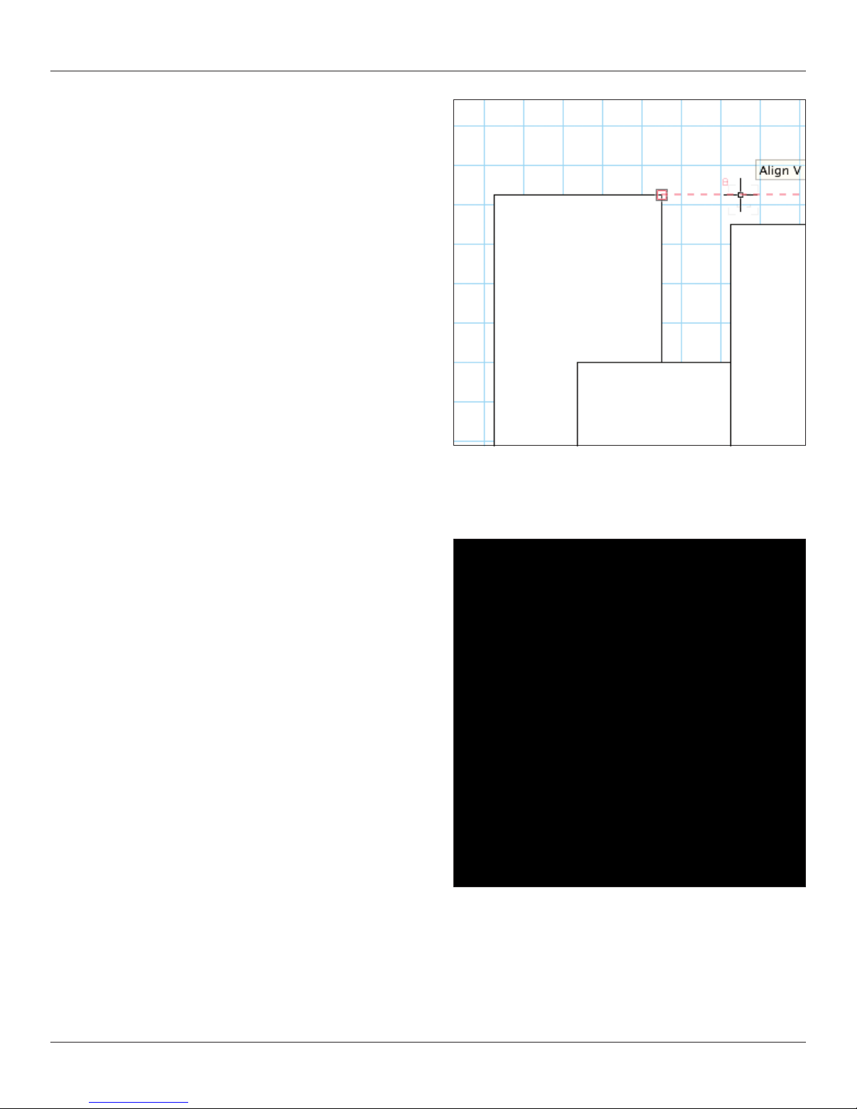
Select the rectangle tool and hover the cursor near another rectangle.
Note the smart cursor hints and alignments indicated. Align with a
corner, indicated by the red extension line and hit the “T” key to lock
in that alignment.
Try this again. When hovering near a snap point, hit the “Z” key to
enable the snap loupe which allows you to zoom in close until you
click the mouse. You can also use the snap loupe when you want to
nish drawing a shape if aligning to another point.
Select All (command-A) and delete the various rectangles.
30 Vectorworks 2010 Products
Page 31

Vectorworks Spotlight 2010 Getting Started Guide
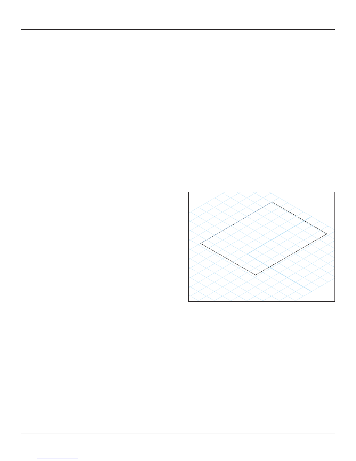
Double click on the rectangle tool and enter the following data:
width=3” [76.2mm], height=3” [76.2mm], deselect position at next
click, and select the middle circle in the object position locator. Then
in the data elds next to the object position locator, enter x=0 and
y=0. Click OK. You will have a square in the middle of the page.
Double click on the circle tool. Enter the following data: radius=5’
[127mm], deselect center at next click, and enter Ctr x=0 and Ctr
y=0. Click OK. You will have a circle in the middle of the page, on top
of the square.
We’re not going to use this function right now, but I want you to notice
the Circle by 3 Points option. This options also appears in Arcs and
Curved Walls. I have found this to be very useful in tracing curves
and in designing the right size circle or arc.
Vectorworks 2010 Products 31
Page 32

Vectorworks Spotlight 2010 Getting Started Guide
Select all and go to Modify>Clip Surface. You will now only see
the circle selected. Delete the circle. The square has been clipped
by the circle.
Double click on the circle tool. Enter the following data; radius=1/2”
[12.7mm], deselect center at next click, and enter Ctr x=1.5”
[38.1mm] and Ctr y=1.5” [38.1mm]. Click OK. You will have a circle
over the top right corner of the square.
Select all and go to Modify>Add Surface. The circle has been
added to the square.
32 Vectorworks 2010 Products
Page 33

Vectorworks Spotlight 2010 Getting Started Guide
Let’s make this a 3D object. Go to Model>Extrude (Command-E)
and enter 3” [76.2mm] in the Extrusion eld and click OK.
Select the Flyover tool and look at the object in different views. Do
the same with the current view drop down menu in the View Bar and/
or your numeric keypad.
Interactive Origin Mode
•
Object Center Mode•
Active Layer Plane Origin Mode•
Working Plane Origin Mode•
For our purposes, select Object Center Mode and click and drag to
rotate the View. Experiment with the other options.
Now take a look at the object in different views. Do the same with the
view drop down menu in the View Bar and/or your numeric keypad.
These are the basics of making all kinds of 2D and 3D objects.
Vectorworks 2010 Products 33
Page 34

Vectorworks Spotlight 2010 Getting Started Guide
Other 2D Shape Tools
We have seen how simple it is to draw using simple 2D shapes,
add and subtract from those shapes and extrude into 3D. Let’s look
at the other 2D tools in the Basic Tool Set and see how they can be
used. Specically how they can be used together to make virtually
any shape in 2D and 3D.
You can easily nd which tool is which by hovering and waiting for
the descriptive text to appear or go to the help les.
Oval
When you went to make the circles before you may have noticed
two similar tools, the circle and the oval. Let’s look at the Oval Tool,
select it and notice the different options in the Tool Bar. Draw a few
ovals using the different options, some freehand, some with
absolute positioning and then with the Floating Data Bar.
Regular Polygon
Like the Circle and Rectangles, the regular polygon allows you to
make simple multi-sided objects.
Polygon and Polyline
These tools allow for freehand drawing. The Polygon only has
straight lines, but the Polyline tool allows you to introduce curves.
Consider tracing a scanned drawing or placing Locus points. You
can also use the 2D Line Tools and absolute positioning to create
a set of guides. Then connect the dots with the Polygon Tool.
34 Vectorworks 2010 Products
Page 35

Vectorworks Spotlight 2010 Getting Started Guide
Offset
The Offset Tool allows you to quickly duplicate a surface inside or
outside of an object. Select the tool and go to the tool preferences in
the Tool Bar. Consider that if you have just drawn some crazy shape
that you will use as a platform and you want to allow for the thickness
of the reveal and/or the structure. Simply off set the shape.
Vectorworks 2010 Products 35
Page 36

Vectorworks Spotlight 2010 Getting Started Guide
Fillet and Chamfer
The Fillet and Chamfer tools are very similar. These terms are
generally used in cabinetry and millwork, not necessarily theatre. In
each case, these tools trim the corner of a polygon. A Chamfer is a
straight line cut and a Fillet makes a rounded corner. In each case,
select the tool and trim the edge of a rectangle. First select a mode.
They each have the same 3 modes. The rst Chamfer or Fillet adds
the detail, the second split’ also trims the lines of the polygon to the
detail, while the third ‘trims’ the original shape to the new detail.
Select the tools, set your preferences and mode then hover
over the edge of a poly, if eligible for Chamfer/Fillet, the edge will
be highlighted,click and drag to an adjacent edge and it too will be
highlighted. Click to execute.
Rotate
So, you have all this cool stuff drawn and it is not quite angled the
way you desire? Enter the rotate tool. Double click on the rotate tool
and any/all of your selected objects can be rotated to a specic
angle, up to 1/100 of a degree. You can also freehand rotate by
clicking on an object, dragging to another point on the object and
clicking then dragging. Note that Vectorworks tells you when you are
horizontal or vertical. Note also that you can rotate and duplicate in
the Tool Bar.
Mirror
Designing a symmetrical set? Draw one side and let Vectorworks
draw the other. The Mirror Tool has 2 modes in the Tool Bar, Mirror
and Mirror and Duplicate. Select your objects, select the Mirror Tool
and Mode and click and drag. Hold the shift key down as you drag if
you want to constrain the angle of the mirroring.
Drawing with Lines and Making Objects
Some people are more comfortable drawing with lines rather than shapes. They would not be me. If this is you, then you can easily
draw many of the same shapes using the line tool and the arc tools with either absolute placement or the smart cursor. Once you have
your shape drawn, go to Modify>Combine into Surface and click the paint bucket in the shape or go to Modify>Compose and you
will have a shape rather than a series of lines.
36 Vectorworks 2010 Products
Page 37
Vectorworks Spotlight 2010 Getting Started Guide
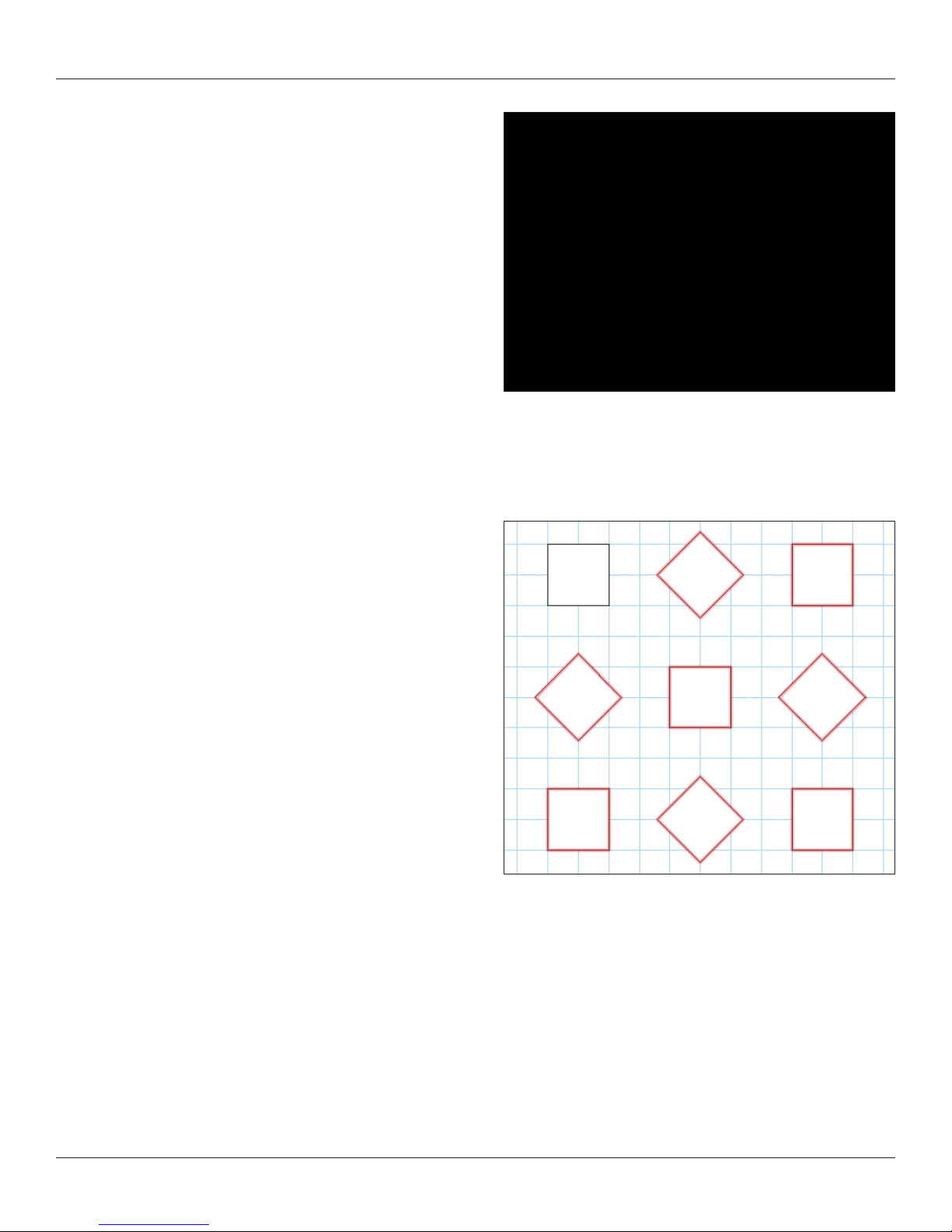
Duplicate
So you have this wonderful shape. Now you want more. Maybe you
want to have a pattern. All of that Absolute Positioning! No worries,
meet Duplicate Array! Go to Edit>Duplicate Array and note that at the
top left drop down menu you have three modes;
Linear Array
•
Rectangular Array•
Circular Array•
Note: Options for each mode are different but they do allow
you to offset in different ways and to rotate the object(s) that you
are duplicating.
In addition to the Duplicate Command, you should review the Move by Points Tool in the Basic Toolset. Move by Points combines some
of the functionality of the Duplicate Command, the Align Command (Modify>Align) and the Move Command (Modify>Move). The
Move by Points Tool is precise while allowing for free-form drawing.
As always, experiment.
Vectorworks 2010 Products 37
Page 38

Vectorworks Spotlight 2010 Getting Started Guide
Convert to Polygon and Re-Shaping
Lets assume that you have not been able to make the shape that
you like yet. Or perhaps, like me, you like this method of working
with 2D shapes. Draw a rectangle. A rectangle is not a polygon.
You can make a rectangle into a polygon by Adding or Clipping. In
this case we will select the Rectangle and go to Modify>Convert>
Convert To Polygon.
Ok, now what, it looks the same?
Select the 2D Reshape Tool from the Basic Tool Set and let’s go to
town. You can also double click the polygon and the 2D Reshape
Tool will self select. Let’s look at the options:
Move points
•
Convert Points•
Add a point•
Subtract a point•
Hide or Show Edges•
Note: That when you select Add or Convert, other options become
available. Note also the options for selecting points.
This is a very robust tool and very useful if you like sweeping curves.
Your rectangle now shows eight points, or more precisely four points on the corners and four midpoints. Let’s experiment with the tool,
try these things and then undo so you always return to the basic rectangle. First select the rst option on the left; Move polygon handles
Mode. Grab a corner and move it around. Undo. Select the Delete Vertex Mode and delete one of the corners so that you have a
rectangle. Undo. Select Add vertex and be sure that you have the Corner Vertex option selected. Note that you can add and manipulate
points only at a mid-point. Select the Change Vertex Mode and select Bezier Curve. Click on a corner and observe the curve.
Manipulate this curve with the Move Mode. On another corner, convert the corner point to a Cubic Spine Point. Manipulate the curve
and compare how they differ.
Exercise
Up to this point the exercises given have been pretty vague and about experimentation. These things have been suggested to
acclimate you to the Vectorworks environment. Now you’re actually ready to do something.
Create a document with 11 design layers. On one layer create a rudimentary title block (like so much else we’ll get to using proper title
blocks later), with your name and date. This should be a letter size document with 1:1 scale. Use each of the layers to work with the
primitive drawings tools to make a few things. Play. Use classes.
Use Layer visibility to control what is visible for printing to hard copy or PDF.
One of my former students, Matthew William Anastasio (Montclair State University ‘08), has provided a sample project on the DVD.
Don’t try to copy his work, make this your own, but see the possibilities.
38 Vectorworks 2010 Products
Page 39

Vectorworks Spotlight 2010 Getting Started Guide
2D — 3D Drawing & Modeling
We’ve covered simples extrudes which allow for the creation of
many but not all 3D objects. Let’s take a look at some of the other
methods we can use to model in the 3D space. As always, we’ll
also come to some other options later as well
Sweep
Sweep (Model>Sweep) is a simple way to quickly create
modeled or sculpted round 3D objects like balusters, nials or
martini glasses. As always we start with simple 2D primitive
forms. Consider sketching a rough of your nal object and/or
using a tracing layer with a placed JPEG or PDF image. PDF
images created as vector les are especially useful for tracing
in Vectorworks as you can snap to points in the PDF.
Please refer to the le Martini.vwx included on the disc. The le
shows how I have broken down each step onto different layers and
classed all of the objects.
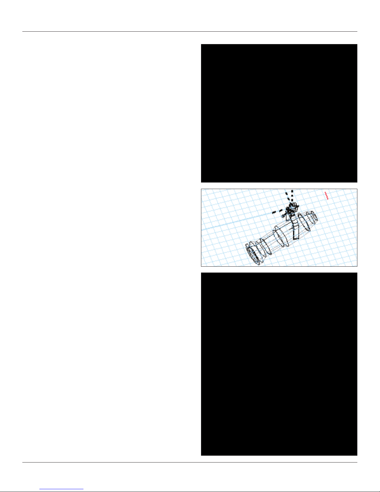
For illustration purposes, I am going to draw a few guidelines and
use the intersections of these guides to create a martini glass and
some liquid in the glass. I am using the 2D lines for the guides.
Next, I have used the Polyline tool to draw the basic shape. I like to
begin with all corner points and use the 2D Reshape tool to add my
curves and adjust the shape.
Vectorworks 2010 Products 39
Page 40

Vectorworks Spotlight 2010 Getting Started Guide
Note: I add what seem to be ‘extra’ points when drawing with
corner points.
Once I had the basic glass shape, I duplicated its layer and edited
the glass to become the form needed for the liquid.
I used the 2D Reshape tool to remove points and once I had a simpler shape,
I used the Clip Tool (Basic Tool Palette) to delete enough of the form so that
the liquid would not spill. This ensures that the inner prole of the glass and
the outer prole of the liquid match.
Once I nished that shape, I moved the liquid back into the glass by
duplicating the layer with my glass prole and then copying the liquid prole
from its layer to the new one using Edit>Paste in Place. Paste in Place will
keep objects in their exact absolute position as long as you paste between
layers of the same scale.
40 Vectorworks 2010 Products
Page 41

Vectorworks Spotlight 2010 Getting Started Guide
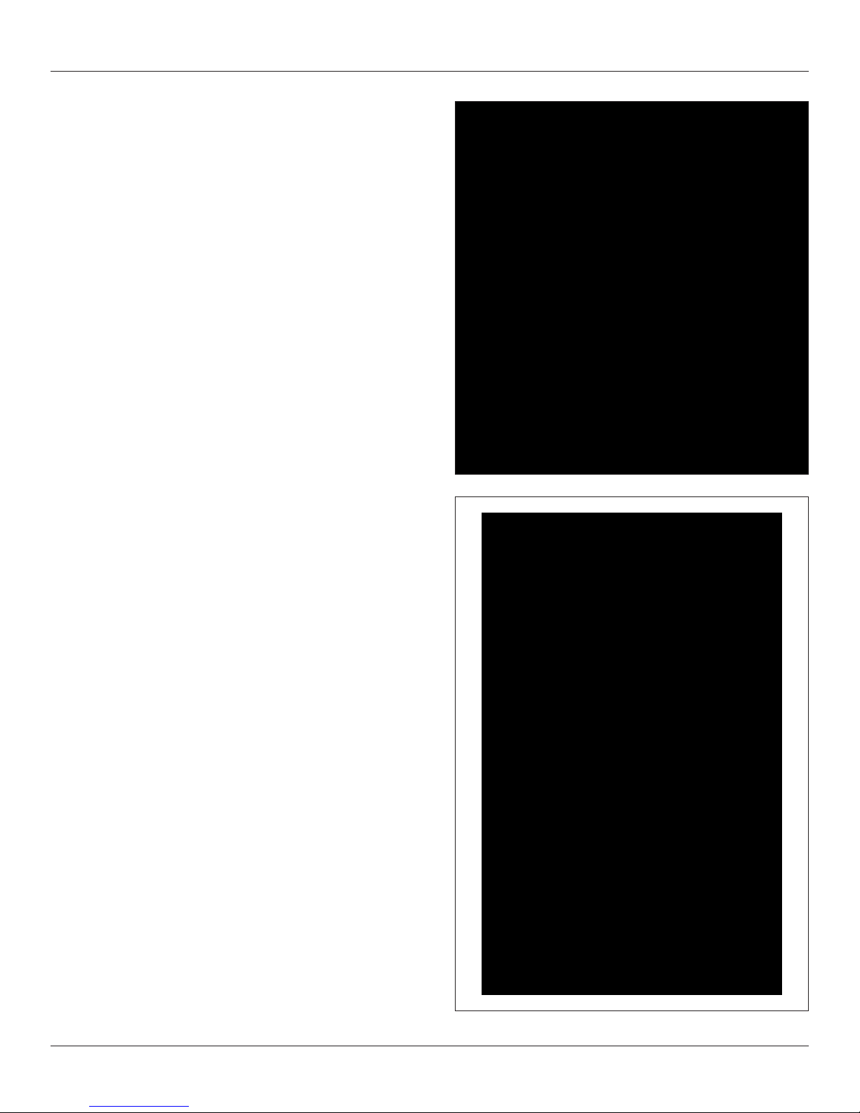
With my shapes drawn and positioned, I go to Model>Sweep,
enter a full 360° and accept the other defaults and almost
instant Martini.
You can add the olive later and once you have seen and explored
the 3D Drawing Tools.
My example rendering skips a few steps in the book, but I hope it
whets your appetite for learning more.
Vectorworks 2010 Products 41
Page 42

Vectorworks Spotlight 2010 Getting Started Guide
Extrude Along Path
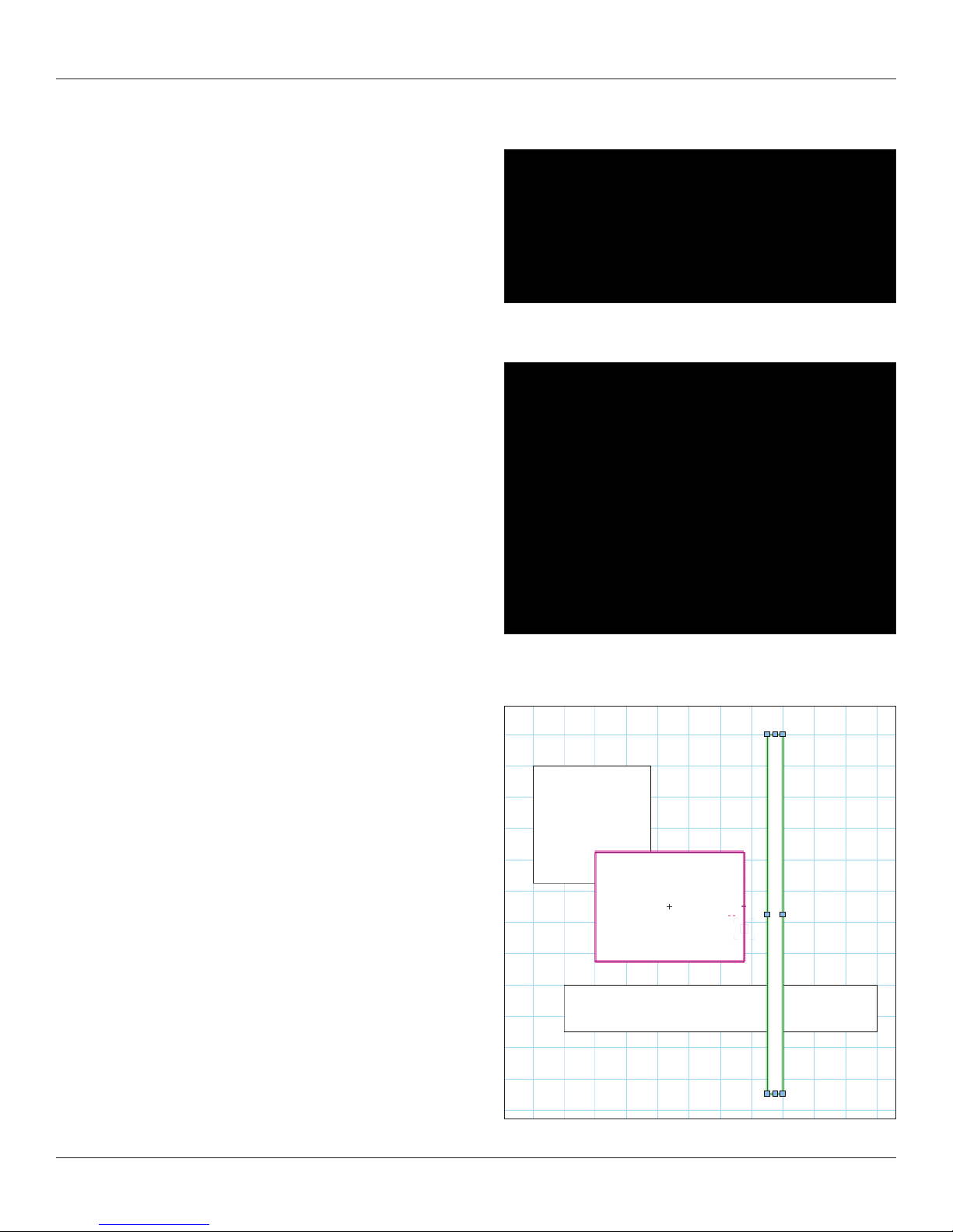
I use extrude along path for many objects such as picture frames or
an ornate proscenium. Draw a rectangle, select a solid crown
moulding prole and Model>Extrude Along Path.
Extrude Along Path extrudes around the center of the prole
objects. This small bit of information is important in determining the
size of your path. If you want the outer perimeter a certain size,
your path needs to subtract the width of your prole.
I have taken a standard moulding prole. In this case I previously
traced the catalog from one of my local lumber yards. Vectorworks
ships with a library of US nationally available proles as symbols.
You can insert one of these symbols and convert to group. I added
a small piece of wood to hide the edge of the artwork, placed a
rectangle, selected the two objects and the Model>Extrude Along
Path Command.
Note: Double clicking on the nished piece allows you to edit
(or ip) the prole or the path.
Chain Extrude
The Chain Extrude tool is located in the Building Shell Tool Set.
You can create a cornice with Extrude Along Path. You can create a
cornice with repeating corbels using Chain Extrude.
Create the proles as you would normally. If you want a continuous
object and a repeating object, create the continuous object rst.
Select the object(s), select the Chain Extrude Tool, follow the
prompts and draw the line required in the plan view.
42 Vectorworks 2010 Products
Page 43

Vectorworks Spotlight 2010 Getting Started Guide
Multiple Extrude
Multiple extrude allows for the creation of truncated and tapered
objects. Draw a simple 2D primitive, a rectangle or a circle. Offset
inside of that object. Select both proles and go to Model>Multiple
Extrude. Set a height and use the yover tool to examine what you
have made. Double click on the object to edit, or edit in the OIP.
Note and experiment with the fact that these objects do not have to
be centered over one another.
Similarly, see the type of results that you can achieve with a single
primitive and using the Model>Tapered Extrude command.
Editing 3D Shapes
All of the 3D shapes we have created can be edited or modied by
double clicking on the shape. At that point you can change the 2D
primitives used as the foundation of your form.
Exercise
Like in the 2D Primitive section, create a le with at least 11 design
layers. You will need more, but one layer should contain your basic
title information and 10 layers should contain object that you have
drawn and modeled into 3D using the methods described above.
The additional layers will be tracing layers. Assume that you will
draw some objects essentially freehand or draw objects that you
have sketched out with some basic dimensions and worked off of
guidelines you have drawn for yourself. Search the internet and nd
a few JPEG’s and PDF les to trace. Be sure to nd a raster PDF
and a vector PDF to see the difference in tracing.
Vectorworks 2010 Products 43
Page 44

Vectorworks Spotlight 2010 Getting Started Guide
3D Modeling
We’ve looked at a number of ways to work in 2D and convert those objects to 3D. Let’s take a brief look at ways to manipulate 3D
objects and work directly in 3D.
Manipulating Solids
Model>Add Solids and Model>Subtract Solids are the 3D equivalents of Add & Clip Surfaces. Take them out for a test drive, create
a couple of intersecting 3D Objects, select them both and try Adding and Subtracting. Note the red outline provided by the application
so you can visualize how you are combining the objects. Like in the 2D world, you can also work with more than two objects at once for
some operations.
After you have created objects by adding or subtracting, you can double click on those objects to edit or move the base forms.
3D Primitives
Hover around the 3D Modeling Tool Set and see what tools are installed. Stay away from anything that says NURBS for right now.
NURBS are complex curves and surfaces, which help accomplish amazing modeling tasks, but right now we’re going to use some
more basic approaches. After we have had a bit of time to explore these tools, we’ll take a look at NURBS, in the last section.
In a new document with 1:1 scale, with the 3D Polygon tool, draw a free form shape. In the OIP, enter a Z value and notice that you
have a planar object oating in space. By carefully placing 3D Locus Points in space and connecting with the 3d Polygon T
create forms that would be difcult or impossible with other techniques.
ool, you can
Experiment with the other 3D Modeling Tools and make a variety of forms. When you draw with the 3D Rectangle Tool, you will see that
you are asked for the extrusion before drawing. You still have access to the Floating Data Bar and you do not have the ability to
absolutely place the object.
44 Vectorworks 2010 Products
Page 45

Vectorworks Spotlight 2010 Getting Started Guide
Project — The Lighthouse
Believe it or not, you now have enough knowledge to model and
render something like this. Well maybe not render, but read on
and that too will be explained.
Where I teach, this project is seen as a rite of passage. It is
always known as The Lighthouse even though I have varied the
assignment from year to year. The lighthouse les are included
on the disc, but you can challenge yourself with other great
architectural landmarks. The United States Government HABS
(Housing and Building Survey) Drawings from the Depression
Era WPA is a great resource.
http://memory.loc.gov/ammem/collections/habs_haer
The JPEG of the Cape Hatteras Lighthouse is a half section/half
elevation. Import the JPEG and use the Modify>Scale and Scale
to Dimension commands to be sure that the drawing is in scale
and to set a layer scale. This is why I always ask that a scale bar
be included on every drawing. On a new layer trace and model
the lighthouse. Consider using different layers for different
elements and either stacking the layers or assembling on one
master layer.
Vectorworks 2010 Products 45
Page 46

Vectorworks Spotlight 2010 Getting Started Guide
Plan your project, consider the number of nishes and object types that you will wish to class. Plan rst, make the classes rst. For a
nished product, I ask to see a plan, section and elevation of the Lighthouse. Plus a rendering. Your choice of colors and textures, you
do not have to match the original scheme, be creative. Include a human gure image prop for scale in the rendering and use the human
gure 2D symbol in the annotation layers of the section and elevation. I do not require the spiral staircase, I nd that an object that
complex adds too much time to the process. I only require the top part indicated in the drawing. I offer extra credit if you can arrange
Viewports to match the original drawing.
Don’t forget the graphic scale.
Once you can model the lighthouse, everything else drops into place.
46 Vectorworks 2010 Products
Page 47

Vectorworks Spotlight 2010 Getting Started Guide
Using the Wall Tools
Open a new document with your Default.sta template.
We are going to create a theatre space. As you have noticed, VW creates a zero-zero point on the page. We are going to assume that
zero-zero is the intersection of the Plaster Line and the Center Line in a traditional Broadway size proscenium theatre. We are not
going to worry that our theatre may go off the page in the Design Layer.
This is what we are going to draw:
In the View Bar set the Class drop down to your normal line weight class. From the Basic Tool Set, and in the Top/Plan view, double
click the 2D Locus tool and place a locus x = -35’ [10.668mm] y= -15’ [4.572m].
Vectorworks 2010 Products 47
Page 48

Vectorworks Spotlight 2010 Getting Started Guide
Wall Tool
Select the Building Shell Tool Set and select the Wall tool. Select the right control line option in the Tool Bar and set the wall’s Overall
Thickness at 9” [228.6mm] in the Wall Tool Preferences in the Tool Bar. Click on the locus, drag up, tab into the Floating Data Bar and
enter 30’ [9.144m] in the length; tab to the wall angle and set to 90°. Hit return and click on your page. Drag to the right. Tab into the
FDB and enter 70’ [21.336m] at 0°, hit return, and click and drag down the page. Tab into the FDB and enter 30’ [9.144m] with -90°,
click return and double click.
With the Wall tool still selected, go back to the wall preferences and change the wall thickness to 24” [.610m]. Select left control line
option. Click on the Off stage edge of the DSR (Down Stage Right) wall and drag to the off stage edge of the DSL (Down Stage Left)
wall. Double click. Use the Zoom Loupe as needed.
It is likely that the three walls we rst drew will be separate from the new wall; select the Wall Join tool, click on SR wall and drag to the
thick wall. Repeat on the SL side.
Select all the walls and change the wall height (+Z) to 50’ [15.240m] in the OIP.
Floors
Select the Rectangle tool from the Basic Tool Set. Click on the
USR outside corner of the wall structure and drag to the outside
corner point of the DSL. Your theatre has disappeared! We’ll get it
right back.
Go to AEC>Floor and set the bottom Z to -36” -[.914m] and the
thickness to 36” [.914m] and click OK. Go to Modify>Send>Send
to Back. Bam! The theatre has returned and you have a stage.
Note: Extruding objects with a positive value extrudes them up
from the zero Z and extruding with a negative value extrudes down
from zero.
Door and Window Tools
Now we need a proscenium opening. From the Building Shell Tool Set, select the Door Tool and hover over the middle of the down
stage wall. The Smart Cursor will indicate “Midpoint” when you are in the right place. Double click to insert the door. Don’t worry about
the size or the swing direction. When the Door Settings dialog opens, select the General tab and set the opening to 40’ [12.192m]
wide and 18’ [5.4864m] tall and change the conguration to Cased Opening. Click OK. At any time, use the Flyover tool, the numeric
keypad or the Current View drop down in the View Bar to admire your work.
Note: The Window tool work in the same basic manner as the Door tool.
Now we need some basic masking.
48 Vectorworks 2010 Products
Page 49

Vectorworks Spotlight 2010 Getting Started Guide
Curtain Tool
Select the Spotlight Tool Set and the Curtain Tool. Select the Preferences in
the Tool Bar and change the Current Height to 24 feet [7.315m]. Click to insert
the curtain and hit Tab to activate the FDB, place a 60’ [18.288m] long curtain
25’ [7.620m] upstage of the proscenium and -30’ -[9.144m] from the centerline.
You may modify all of these options in the OIP.
Do the same to create a 10’ [3.048m] by 24’ [7.315m] leg, 20’ [6.096m]
upstage of the plaster line. With that leg selected, go to Edit>Duplicate Array
and select Linear Array from the drop down menu. Make 3 duplicates -5’
-[1.524m] on the Y axis. Select ALL the legs and then the Mirror Tool from the
Basic Tool Set. Select the
Duplicate and Mirror mode and nd the mid-point of the US wall. Click and
drag down; hold the Shift key to constrain the downward movement to vertical.
Release the mouse.
Duplicate the US drape using the Edit>Duplicate Array command, making
one duplicate -12” [.305m] on the Y axis. In the OIP, change the Curtain Height
of the drape to 10’0” [3.048m], the Z value to 18’ [5.486m] and the Curtain
Length to 60’ [18.288m]. Duplicate three times as you did the legs to create
full set of borders.
Vectorworks 2010 Products 49
Page 50

Vectorworks Spotlight 2010 Getting Started Guide
Create Seating Layout
You now have a fairly complete and well masked stage house. Let’s add a few
seats. Draw a rectangle from the midpoint of the DS edge of the stage (draw
from CL to SR) 20’ [6.096m] wide by 12’ long [3.658m], select it and go to
Modify>Move>Move and move -2’ -[.610m] on the X axis.
With this rectangle selected, go to AEC>Create Seating Layout. Select the
padded Theatre Seat and click ok. When prompted, select the focus straight
ahead, and seats are automatically created. Congure the arrangement in
the OIP.
Curved Wall Tool
Now we need a bit of a set. Select the Round Wall tool from the
Building Shell Tool Set. Click on the Preferences and set the width
of the wall to 4’ [1.219m], and select the Left Control Line. Start to
draw from the center of the stage and draw an arc that is 270° so
that the arc ends facing your audience. Adjust the placement and
height in the OIP.
50 Vectorworks 2010 Products
Page 51

Vectorworks Spotlight 2010 Getting Started Guide
The wall height should be set to 42” [1.067m] but now we are going to edit the
wall with the 3D Reshape tool from the 3D Modeling Tool Set. Switch to the Left
View and grab the DS Edge of the curved wall; drag it to the ground, changing
your wall to a ramp.
This basic editing procedure, which works in much the same manner as using
the 2D Reshape tool on a Planar Object allows the creating of angled and/or
gabled roof lines on any wall object.
Wall Sculpting
From the midpoint of the wall face that is parallel to the plaster line,
draw a 6” [152.40mm] by 48” [1.219m] rectangle. Extrude to 4’
[1.219m] and from the DS midpoint of this object draw a 4’ [1.219m]
by 4’ [1.219m] rectangle. Extrude the last rectangle to 6” [152.40mm]
and change its bottom Z to 4’ [1.219m] in the OIP.
Lastly we need a wall. Draw a 2’ [.610m] deep by 24’ [7.315m]
wide by 20’ [6.096m] tall, 21’ [6.401m] US of the plaster line. This is
a bit boring, so we’ll add a few niches. On the midpoint, center a
rectangle 1’ [.305m]deep by 2’ [.610m] wide. Extrude to 7’ [2.134m]
and set the bottom Z to 4’ [1.219m] in the OIP. Duplicate two of
these elements -4’ -[1.219m] on the Z axis and two also 4’ [1.219m]
on the Z axis. Select all of the elements and the wall. Go to
AEC>Create Wall Recess and accept the defaults.
Note: You can also add Wall Projections if you like. The process is
very much the same.
In most every case here, we have used the default settings. It is
critical that you go back and experiment with other settings to
see how they affect your choices and possibilities experimentation
and observation is the only way that a new user can master
the program.
Before we move on, let’s look at some related tools that we have not
used in this exercise.
Vectorworks 2010 Products 51
Page 52

Vectorworks Spotlight 2010 Getting Started Guide
Column Tool
Let’s go back to the Building Shell Tool Set and do a little hovering. You will nd the Column Tool, but not the Pilaster Tool. Edit the
workspace to nd and add the Custom Stair Tool. As you look for this tool, note some of the other available options that you may want
to use in the future.
In a new le, build yourself a simple square room with the Straight Wall
Tool, make it 20’ [6.096m] square, center on the 0-0 point
of your page. Be aware now of the Wall Join Tools (you should have noticed these as you were just hovering over the various
Building Shell Tools) and that you can add interior walls and attach them to your perimeter walls. Experiment with these functions
at your leisure.
Select the Column Tool and go to the Preferences in the Tool Bar.
While it is not yet possible to create a full Corinthian Capital in
Vectorworks, you do have a lot of options in regard to base, capital
and shaft. Make some choices and Inset a Column into your room.
Note: You can place precisely with the Floating Data Bar.
Remember if you are doing a project with a million or so columns of
the same design, create one column, convert it to a symbol and
then if you need to change the column, you only need to edit the
symbol. Conversely, if you need one column to be different, you
can convert it to a group and edit that one instance traditionally. If
you need a number of columns to be different, you can duplicate
the symbol in the RB, edit the new symbol and use the replace
symbol function in the OIP.
52 Vectorworks 2010 Products
Page 53

Vectorworks Spotlight 2010 Getting Started Guide
Stair Tools
Let’s just note that Vectorworks comes with a variety of stairesque
tools: The Simple Stair, Custom Stair (in the Designer package and
Architect module) and Ramp should be visible. There are also
Elevator and Escalator Tools available in the Designer package or
Architect module. Look around. Note all of these tools are suitable
for use in entertainment design. These tools were created with
architects in mind. Typically architects will be inserting stairs that
will be dened by specications of existing products. It is unlikely
that an architectural rm would be drawing a Victorian Staircase or
a curved French stair and railing. An entertainment designer would
create that in 3D, likely from scratch. You should be able to create
that kind of drawing. Soon. That’s why you’re also working on that
Lighthouse image while working through this book.
Be aware here, that the door, window and stair tools are not
classed like other objects. Within the preference dialogue for each
of these items you will nd a drop down assigning pre named
classes to specic elements. These classes need to be assigned,
Vectorworks will create the classes and you then need to go back
and dene the class attributes. Once created, if you want consistent line weight, you can add to your stationery.
Nevertheless, the stair tools have some application in indicating
stage house or backstage architectural details and escape stairs.
So let’s look at the Custom Stair Tool. Select the tool and click in
your drawing. You will see the dialogue at right that allows selection
of the default stair symbols. On Selection of a symbol, the Custom
Stair Dialogue opens.
Vectorworks 2010 Products 53
Page 54

Vectorworks Spotlight 2010 Getting Started Guide
I see much of this dialogue as similar to others we have covered,
but with a lot of depth for creating different stairs. Explore the
dialogue and create a stair case.
Note: The choices of available classes in the drop down menus.
As you have explored the contents of the Vectorworks libraries, you
will note that there are other stair symbols available for use in the
libraries. Each customizable to your specic needs.
We’ll get to the techniques needed to create that ornate stair case
for the next Fred & Ginger movie a little later on.
54 Vectorworks 2010 Products
Page 55

Vectorworks Spotlight 2010 Getting Started Guide
Roof Tools
Let’s make your 20’ [6.096m] square room into a small house. In
the plan view, select the left wall and use the drop down menu in
the view bar to go to the Left view. Select the 3D Reshape tool from
the 3D Modeling Tool Set, select ‘+’ option to add a control point
and grab the left side of the wall. Note that the cursor changes
shape to the add point cursor. Grab the corner and drag up and to
the middle, tab into the Floating Data Bar. Enter 9’-6” [2.896m] and
10’-0” [3.048m] and 14’-0” [4.267m] and enter and click. Do the
same on the opposite side.
Vectorworks 2010 Products 55
Page 56

Vectorworks Spotlight 2010 Getting Started Guide
Nice house, no roof.
Select the four walls and go to AEC>Create Roof. For our
purposes, accept the defaults and Vectorworks will build a hip roof
that can be edited. By default you will have a four sided hipped
roof. Double click on a control point on a side of the roof and select
gable, repeat on the opposite side.
An alternate approach, like the Floor command is the AEC>Roof
Face command. Go back to your basic theatre drawing and
draw a 2D rectangle over the space as you did for the oor.
With that object selected go to AEC>Roof Face and create a
simple slab roof.
56 Vectorworks 2010 Products
Page 57

Vectorworks Spotlight 2010 Getting Started Guide
Drawing a Light Plot
We have a basic theatre and set, and we have added some resources into our document. Now we can begin to create a light plot. In
Top/Plan view, your drawing should look something like this:
First we need some instruments in our document. Go to the Resource Browser use the drop down menu (look for the little triangle) to
access the favorite ETC symbols and import the 26° and 50°s 4’s, by right clicking and selecting Import.
Label Legends
Now we will create a Label Legend format for our instruments.
A label legend provides information around your units. Go to
Tools>Label Legend Manager and select Add. I’m calling this one
LL-1 for brevity. Once created click in the left column to make the
legend active.
Vectorworks 2010 Products 57
Page 58

Vectorworks Spotlight 2010 Getting Started Guide
Select Edit Fields. For simplicity I have only selected three
of the many possibilities: Unit Number, Color, and (way down
near the bottom) Focus. To select a data eld, just check in
the left column.
Note: That in the right column you can put the information in a
container.
Containers are symbols, and to change the container,
you must edit the symbol in the Resource Browser. We’ll
cover many of these additional details in the long version
of this guide.
Click OK. Select Edit Layout which will open the Edit Symbol
window, dened by the colored border. From here you can
select and drag the labels from the left column around the
instrument. The Smart Cursor will help you align the data. You
can also use the Align command. Text can be formatted from
the Text Menu. Click Exit Symbol when nished.
Focus Point Objects
Now we’ll need some focus points. Go to the Spotlight Tool Set
and select the Focus Point Tool. I’ve set up a simple downstage
wash, an area at the top of the platform, and two areas to the light
the rear wall. Use the midpoint of the stage and the Smart Cursor
to set your rst area. Duplicate in an array as needed.
58 Vectorworks 2010 Products
Page 59

Vectorworks Spotlight 2010 Getting Started Guide
Lighting Positions
Next you’ll need some electrics. Go to the Resource Browser use the drop down
menu to access the Lighting Positions le we already added as a favorite, and
select the 50’ pipe symbol, right click (control-click on a Mac) and select import.
Revert back to the active document in the resource browser by clicking the Home
icon and double click on the 50’ pipe to select it. Then go to the Spotlight ToolSet
and choose the Light Position Obj Tool.
Align the insertion point with the midpoint of the DS edge of the stage, press
the “T” key and position. Adjust the position and set the Z height in the OIP.
Name the position in the OIP on the Data tab. Repeat for the onstage electrics.
Consider the Vectorworks duplication options for adding electrics.
Vectorworks 2010 Products 59
Page 60

Vectorworks Spotlight 2010 Getting Started Guide
Truss
The Truss Tools in the Spotlight Tool set can be used as Lighting Positions. The Straight and Curved Truss Tools should be self
explanatory by now. They insert hybrid objects. You can specify sizes to create either custom truss or objects that match truss you know
you will be using. There are Truss Symbols for many manufacturers in the Entertainment Library.
If you are using truss, draw the elements you need, select them and choose Modify>Convert>Convert to Lighting Position. You can
then set a Z height, hanging angle (for Straight Truss pieces) and such in the OIP.
Creating Lighting Positions
The Vectorworks libraries are terric resources, but they cannot anticipate everything any designer will ever need. The application
allows you to create to your particular situation. Any hybrid symbol inserted with the Lighting Position Tool (or select a symbol and go to
Modify>Convert>Convert to Lighting Position) can be a lighting position.
You can easily create a lighting position with the Truss Tools or with simple primitives. The Truss Tools are pretty self explanatory at this
point, they create hybrid objects and there is a library of commercial available truss included with the package. Let’s use this
opportunity to review creating a hybrid Symbol.
While a lighting pipe is typically round, you can choose to make a round or square (simpler geometry, smaller le size) extrusion
2” [50.80mm] by 2” [50.80mm] by your choice of length. You will likely want to assign a class to the 3D element. Make sure that your 3D
component is centered at 0-0 and Modify>Create Symbol, with the insertion point at center. Name the symbol, click OK and then
right click on the symbol in the RB to edit the 2D component, which currently does not exist. There are two schools of thought on the
2D component; line or rectangle. This is your call, in either event, double click on the 2D tool you need and place the object, the same
size as the 3D (in the case of the line, the same length) at the 0-0 point. Class the new object, and exit the symbol. Y
lighting position.
ou now have a
Inserting Instruments
Double click on the 26° instrument Symbol in the Resource Browser. Notice that Inst Insertion Tool has been activated. Place the
rst instrument on the FOH position at center. Look at the OIP and notice the number of options available. Select a focus for the unit.
On the Light Information tab, select Draw Beam. Click OK. Notice that Vectorworks Spotlight calculates the angle and coverage of the
instrument. You can use this feature to verify your instrument choice. Don’t forget to deselect Draw Beam from the OIP, or you drawing
will become very cluttered and selections will be very unwieldy.
60 Vectorworks 2010 Products
Page 61

Vectorworks Spotlight 2010 Getting Started Guide
Coloring your Lights
From either the Lighting Device dialog box or the OIP, you can assign Rosco, Lee, or GAM color in the color eld. A Rosco color is
noted as R36 and a Lee as L36. Hexidecimal or RGB values can also be entered.
Additional information can be added and transferred to your schedule. When you add color and focus in the OIP, that information will
appear in the LL-1 label legend in Top/Plan view on the plot.
Also note that the instrument added now appears in the
Visualization Palette. Double clicking on the instrument in
the Visualization Palette selects that unit on the plot.
Editing Lights
Lights can be edited and focused in a variety of ways. We’ve
already looked at the all powerful OIP and have seen how that
design control point interfaces between your lights, focus objects,
positions and label legends. Let’s look at other options.
Note: Now that the instrument added now appears in the
Visualization Palette. Double clicking on the instrument in the
VP selects that unit on the plot.
Right clicking on the instrument in the Visualization Palette allows
editing of the lighting properties.
Double clicking on the instrument in the plot allows editing of
various properties including shutter cuts for visualization.
Vectorworks 2010 Products 61
Page 62

Vectorworks Spotlight 2010 Getting Started Guide
Right clicking on a unit offers several choices: Edit, Edit Light and Properties in the
contextual menu. Edit opens the Lighting Device dialogue. Edit Light accesses the
dialogue at right, reaching into the symbol to access the Vectorworks light source
(more on those ahead a few pages). Properties is another route into the OIP data.
Use the Inst Insertion tool and Duplicate Array command to add additional
instruments. Add information as you need in the OIP. Once you have populated an
electric, select the Position and check ‘Auto Number’ in the OIP; the instruments will
number and that information will be added to the plot. If you move units around,
deselect and reselect Auto Number and the information will be updated on the plot.
You should end up with something like this:
Just a few things to nish before we can present and visualize this light plot. Go to
Tools>Reports>Generate Paperwork. Set the paperwork schedules you need, and
then we’ll set up the light plot for printing. For example, select Instrument Schedule
and click Setup to specify what to include in the schedule. We’ll use this later.
62 Vectorworks 2010 Products
Page 63

Vectorworks Spotlight 2010 Getting Started Guide
Adding Accessories
Instruments need accessories: color scollers, barn doors and the
like. You will nd a selection in the Vectorworks Entertainment
Library. You can also make accessories symbols by creating a
hybrid symbol, selecting it and going to Modify>Convert>Convert
to Accessory. Selecting an accessory symbol activates the
Accessory Insertion Tool.
Clicking on an instrument in place with an accessory associates
that accessory with that instrument.
Adding Gobos
Vectorworks comes with a large library of gobos by many
manufacturers. You can easily import a gobo texture into your
document or create a custom black and white or full color gobo.
Any square graphic image can be imported into Vectorworks as a
gobo texture. Got to Modify>Convert>Create Gobo Texture
and follow the steps through the creation of the texture. Name the gobo. We’ll look at creating textures in more depth shortly, simply
accept the defaults. Remember that the gobo projector is only going to the image within a circle within your square image.
Alternately, open or add as favorite via your RB one of the stock gobo libraries and import a gobo texture.
Once you have your texture(s) in place, you can add one or two gobos to any instrument in the OIP.
that you can also rotate the gobo images as needed for visualization.
It is important to visualize and we will be rendering soon, that when you render gobos you need to use the Custom
Renderworks settings.
You can see in the OIP
Vectorworks 2010 Products 63
Page 64

Vectorworks Spotlight 2010 Getting Started Guide
Vertical Lighting Positions
This show probably wants a bit of sidelight. This is going to sound a bit counterintuitive, but it will all make sense when we put the pieces together using the
Create Plot and Model View command later in this section.
You will likely want to create a new label Legend for your booms. I made two;
one with the info on the right and the other with the info on the right. Remember
once you have label Legends, add them to your Default.Sta document.
Also remember, I am not drawing this plot for production, I am drawing this to
illustrate how all these tools work and work together. In production other and/or
different elds would be required. The principles remain the same.
Place a 20’ [6.096m] pipe outside of the theatre architecture SL. Populate
the position with a few lights. I started with one unit to the right of the position.
I assigned the unit to the position and gave it a color and Label Legend. I
duplicated the light down the pipe and Mirrored the units. Now Mirror the entire
position. Reassign the label legends. Name the position and assign the lights to
the position.
Shutter Cuts for Visualization
Double click on an instrument in your plot and open the Lighting
Device dialogue. The right hand tab will be for shutters. I nd this
dialogue simple and easy to understand. It is very interactive. Y
will need to check your work as you go by rendering with the one
light on (the one you are shuttering), but this should be pretty
straight forward.
The key thing here is knowing how to nd the option.
64 Vectorworks 2010 Products
ou
Page 65

Vectorworks Spotlight 2010 Getting Started Guide
Projection/Monitor Tools
Vectorworks includes a number of very useful tools if you will be working with projections onstage, in television, trade shows or
corporate theatre. In the Spotlight Tool set, take note of the Television Tool and the 2 Projection Screen Tools; plain and blended.
These tools work very much like many others covered. Take some time and explore them in a new le. Note that once inserted, you
can change the size of the monitors/screens in the OIP. Note that the Screens show you projector placement and the projection cones
are in 3D so that you can analyze any obstruction issues on the computer and not in the eld.
Photometrics/Photogrid
The Photometrics and the Photogrid Tools provide you with two
ways of ensuring that you have an even wash and that your Focus
Areas are not spread too thin. If you are working on a television
production, Vectorworks use these two tools for measuring the light
from your instruments.
The Photometer Tool in the Spotlight Tool set measures the light at
any given point and elevation on the stage. Draw Beam must be
turned on for this tool to work.
Simply select the tool and insert on the plot. As you turn Draw
Beam on and off for different units or systems, you will have to
Refresh the Photometer Object.
The Photometer Grid tool allows you to create an array of
Photometers across the stage; perhaps one at the center of each
area and one where each area overlaps with the next.
Vectorworks 2010 Products 65
Page 66

Vectorworks Spotlight 2010 Getting Started Guide
Scripting
Don’t let scripting scare you. While Vectorworks does come with its own powerful
scripting language that’s certainly not something we’re going to learn ‘Getting
Started.’ What we can do is create a simple macro. You might want to create
more. Let’s say that you want to change all of the R37 in this plot to another
color. That sounds pretty tedious, even if we don’t have a ton of instruments.
Worse if this were a 500 unit production.
Go to Tools>Custom Selection. Select Create Script and then Criteria. Set the
criteria as illustrated. Note all of the options, this is a technique that can be used
for many things. Once you have all these units selected, you can change the
color in every one with one keystroke in the OIP.
Once you save the script, you will have a new ‘Scripts’ window. To execute the
script, double click on the name.
Want to change different color and that R37 script isn’t doing you any good
because all the R37 is gone. No worries, the script is stored in the Resource
Browser. Open the Scripts folder, right click on the script in question and select
edit from the contextual menu.
Just change the color number and save. The script is ready to run in the
Script window.
If you close your script window, you can always get it back at Window>Script
Palettes>Scripts.
66 Vectorworks 2010 Products
Page 67

Vectorworks Spotlight 2010 Getting Started Guide
Creating Custom Lighting Symbols
Any hybrid symbol can be made into a Lighting Symbol by selecting the symbol in the document and going to Modify>Convert>
Convert to Instrument. In this way, you can place a symbol to represent a practical and be accounted for in your paperwork.
You want that thing to light up?
Not a problem, but we’re going to discuss Vectorworks lights in the next section. Once you review that section, you can come back,
edit your 3D symbol and insert a light. If you are looking to represent a specic lamp type, Vectorworks has a great le of lamps in the
library. You can also import IES data from manufacturers specs to make a specic effect.
Be sure that your symbol either uses the default instrument texture or a texture with cast shadows unchecked for the light to pass out of
the instrument.
Create Plot and Model View
OK, now let’s stand up those booms and get this thing ready for presentation. We have a model and we have lights, but we don’t have
a plot that tells the electricians what to do with that pile of gear.
The Create Plot and Model View command will create a Denition Layer for the boom(s) selected. From that Denition Layer it places
a Design Layer Viewport (DLVP) of the boom(s) in plan on the Plot Layer (this is your 2D Light Plot View). It will also place a DLVP of
the Denition Layer on a new or existing Model Layer. The Model Layer (after you have rotated the booms is used for stage sections
and (rendering).
First a few critical issues:
You must have a layer structure as I have previously described.
•
Your lights and positions must be on one layer.•
If your focus objects are on the layer with your lights and positions, they should be classed together and invisible.•
Be sure that you do not have any Sheet Layer Viewports created that reference the Plot Layer•
Select one of the vertical positions and associated units. Go to View>Create Plot and Model View.
The Create Plot and Model View command moves the selected lights and lighting
positions to a new design layer and references them back to your Plot Layer as
a Design Layer View Port (DLVP). Create Plot and Model also places a DLVP on
an existing Model Layer or it will create a new Model Layer.
The rst dialogue in the process names the new Denition Layer. Since we have
two vertical positions, we will run this command twice. Name each Denition
Layer so you can identify your positions. Check the box next to Vertical.
Vectorworks 2010 Products 67
Page 68

Vectorworks Spotlight 2010 Getting Started Guide
If you have multiple boom positions, you must run Plot and Model View for each boom, or create the booms on Layer separate from
your horizontal hanging positions.
If you include your horizontal positions or have nothing selected when you run the Create Plot and Model Command, all or none of your
positions will become vertical positions.
Denition layers are created at the same scale as the original layer. Objects are placed at the same position as they were originally
drawn. When Viewing the Model or the Plot Layer be sure to turn off all the Denition Layers.
On the Model Layer you can rotate and position the booms so that they will appear correctly in sections and elevations using the 3D
Selection Tool in the Basic Toolset or use Modify>Rotate>Rotate 3D.
In your Model Layer, select each boom (individually) with the 3D Selection Tool, switch to the Top/Plan View (the 3D Selection Tool
automatically switches you from the Top/Plan to the Top 3D only view) and rotate the booms so they face the stage. You can also set
your view from the View Bar and use the 2D rotate tool to rotate the DLVP.
If I create each position manually I will create another Denition Layer and DVLP that contains all the other geometry (It just won’t
rotate) that way all I have on my plot and model layer are DLVPs.
If you view your plot layer and your model layer you are going to see the DLVP on the Plot Layer and the DVLP on the Model Layer.
Use the visibilities options in the Navigation Palette to make your choices.
When we create Viewports to present the drawings, you will
•
Make a Top/Plan Viewport of the Plot Layer, with other appropriate layers visible.
Cut Section Viewports of the Model Layer using • View>Unied View and with other layers visible as required/desired.
Use the Model View, Camera Tool, Unied View and other layers to render and visualize the design and/or specic cues.
•
In the annotations space of your Plot Viewport, you will want to add a 2D symbol indicating boom placement. The 3D View of •
the instruments shows the 3D Detail and you will want the 2D Symbol for graphic clarity.
As always, some of this information jumps ahead. Everything will be claried. .
The Create Plot and Model Command disassociates from Focus Point Objects and shutter cuts, so those associations need to be dealt
with again manually for accuracy in rendering.
68 Vectorworks 2010 Products
Page 69

Vectorworks Spotlight 2010 Getting Started Guide
I have also rendered this simple design, set some light levels, turned some instruments off, added some lights as I felt necessary in the
visualization phase and added gobos. We have reviewed all of those steps or we will review them as we move forward, but you should
make your own design choices. All of these les, like this plot, are relatively simple, to allow for ready understanding of the concepts.
Your work will likely be much more complicated.
You should end up with something like this.
Just a few things to nish, before we can present and visualize this light plot. Go to Tools>Reports>Generate Paperwork. Follow the
directions, make your choices. We’ll set that up for printing in the Presenting your Design section.
Vectorworks 2010 Products 69
Page 70

Vectorworks Spotlight 2010 Getting Started Guide
I have included the image above to illustrate a scene, in this case for A Midsummer Night’s Dream lit primarily with custom gobos.
70 Vectorworks 2010 Products
Page 71

Vectorworks Spotlight 2010 Getting Started Guide
Visualizing your Design
The image below has some classes added, additional lights, and gobos inserted and textures created. This could illustrate one moment
of one cue. Many such views can be created by set designers and lighting designers to convey their ideas to directors, producers,
colleagues and craftspeople.
The rendering and visualization capabilities of Vectorworks Renderworks module are, to me, key to creation of an efcient workow.
For my own work, the ability to update a model and have all of the mechanical drawings and rendering updated is critical to a smooth
operation. Having all of these functions within one suite that communicates internally has proven to be the only path.
Vectorworks and Renderworks provide a number of ways to visualize your drawings. Some of these are pertinent to presenting your
mechanical or designer drawings other are relevant to visualization. Combining these methods also allows designers to include
illustrations within the mechanical drawings.
Renderworks and Spotlight allow lighting designers to visualize moments and cues and present them to directors and colleagues
before working in the theatre. Using the lighting controls and renderings, designers can have cues written well before tech. Time
invested up front can save producers valuable crew time.
For lm or television the camera tool can show specic lens choices and camera placement views of sets. While we will not deal with
the animation tools or third party animation plug-ins, it is possible and easy within Vectorworks to illustrate camera moves or walk
through animations of exhibit spaces or themed environments.
Vectorworks 2010 Products 71
Page 72

Vectorworks Spotlight 2010 Getting Started Guide
It has always been very important to me that renderings and models clearly show clients and colleagues the design intent. Clients
especially do not like surprises. Renderworks allows me to be very specic about what the deliverables will look like, well before
fabrication. Changes made in the 3D space and renderings are much more easily changed than built pieces.
Textures are some of the real magic within Vectorworks, learning to use them well will help you to create effective presentations. You
cannot get to the point of building your ideas if you cannot effectively show your vision to others.
This book is all about the application, but I would be remiss not to say I am ignoring here the paper and pencil process that always
needs to take place as you think and plan.
Rendering Modes
From the drop down menu in the View Bar or by going to View>Rendering you will see a list of available rendering modes. The View
Menu list is longer, so let’s look at those;
•
Wireframe
Sketch•
Sketch Options•
Open GL•
Open GL Options•
Fast Renderworks•
Fast Renderworks with Shadows•
Final Quality Renderworks•
Custom Renderworks•
Custom Renderworks Options•
Fast Radiosity•
Final Quality Radiosity•
We’re not going to delve into every option here. First, let’s look at a
few things related to line drawings.
We have been working, whether you know it or not, in the
wireframe mode which shows every line we’ve drawn. This is not
always appropriate if you want to show an elevation without clutter
or a clear isometric. Consider thinking back to hand drafting
conventions and that Hidden Line or Dashed Hidden Line might
help to clarify our intent. Use (and as always, experiment with)
the Line Render Options dialogue to adjust the look of the
rendering mode.
Custom Radiosity•
Custom Radiosity Options•
Artistic Renderworks•
Artistic Renderworks Options•
Hidden Line•
Dashed Hidden Line•
Line Render Options•
Unshaded Polygons•
Shaded Polygons•
Final Shaded Polygons•
Create Batch Render Job•
Start Batch Render•
72 Vectorworks 2010 Products
Page 73

Vectorworks Spotlight 2010 Getting Started Guide
When rendering, you might want to move from an orthogonal or
isometric view into a less mechanical perspective view. Go to
View>Projection>Perspective.
Open GL renderings are useful for fast preview images to see if
you have your textures in place and properly oriented. I do not see
Open GL as a presentation format. Open GL can be useful for your
own visualization. Open GL does not render backgrounds, which
we will cover next.
This is a sample of Open GL Rendering.
We will focus on some of the Renderworks options;
Fast Renderworks, Final Quality Renderworks and
Custom Renderworks.
This is a sample of Fast Renderworks Rendering.
Vectorworks 2010 Products 73
Page 74

Vectorworks Spotlight 2010 Getting Started Guide
This is a sample of Final Quality Renderworks Rendering. You
will nd that with more complex models, textures and lighting that
the difference between Fast and Final becomes pretty dramatic.
Generally Fast is used for your own pre-visualization and Final
for presentations.
Open GL and Renderworks each place an unseen light source in
your renderings if you have not already ‘lit’ the scene. Since we
will deal with lighting specics next, just work with that source for
the moment.
Radiosity Renderings are absolutely lovely, but they are time and
processor intensive. I mention them here to make you aware of this
option as an advanced concept, but not one for Getting Started.
Layer Backgrounds
In our theatre space, we do no need a background, we have the architecture. However, if illustrating an isolated element or a trade
show space or many other things, you might not like to have to create a world before you render a simple object. Or you might just not
like the basic white background that is the Renderworks Default.
Let’s work in the le you created when you made the 10 3D objects.
Choose to edit your design layer via either the Navigation Palette or the Organization Dialogue. Using your existing le, you have now
the opportunity to create 10 different backgrounds. First note that in the Edit Design Layer Dialogue you can assign a background from
the default backgrounds le. Once we create a few backgrounds, you can also assign a background to a layer by double clicking on the
background icon in the Resource Browser.
So, let’s make a few backgrounds. Exit out of any
dialogues and go to the Resource Browser, right click and
select New Resource>New Renderworks Background.
Let’s take a look at your options here. Obviously, you can
name your background something that will readily remind
you of the content. There are also weather options, which
we will avoid right now as they add considerably to the
rendering time. For the moment, be aware of the options
and plan to go back and test them. Your test le is a good
place for this kind of experimentation as you have minimal
geometry to slow the process.
74 Vectorworks 2010 Products
Page 75

Vectorworks Spotlight 2010 Getting Started Guide
The top drop down will be our focus;
Clouds•
One Color•
Two Color•
Image•
Image (HDRI)•
One color should be pretty clear and having at least
a black background is always useful. When roughing out
ideas, use a black background rather than worrying about the
surrounding architecture. Two colors will give you a traditional
gradient background.
The clouds option is very versatile, certainly useful if you are doing
an outdoor project or if you want to see a simple outdoor scene
behind a set. Clouds also make terric backdrops for free standing
kiosks. The default options make for a lovely day sky. I have found
that by switching the white to black, I get a pretty good night sky. As
always, you need to experiment with the options and render the
options in Final Quality Renderworks to see your results.
Vectorworks 2010 Products 75
Page 76

Vectorworks Spotlight 2010 Getting Started Guide
Image should also be a bit obvious. Nonetheless we will plow on
and discover a few new things. Selecting Image>Options brings
you to a standard OS File Open Dialogue, select an image that you
would like to use as a background, say a park or beach scene. That
selection takes you to the Edit Image Background Dialogue. The
size of the image will be based on the size of your output, no
surprises. But what are Flip H and Flip V? Instead of the X and Y
indicators we have used elsewhere, Vectorworks has changed the
designation in this dialogue to horizontal and vertical. You will also
see placement referred to as I/J/K from time to time (not here), the
functionality is the same as X/Y/Z. Images can also invert or make
the image into a negative image, consider that for some types of
presentation you might want to make a Vectorworks drawing or a
hand drafting into an old style blueprint with white lines on blue
or black.
Simply dened, HDRI (High Dynamic Range Imaging) images
contain lighting data. HDRI images, again, simply, are a composite
of different exposures that Vectorworks can use to ‘light’ a scene.
So, if you’re working on an outdoor project and you have or can
create an HDRI image of the area at a certain time of day (say
Magic Hour), the light data contained in the image and interpreted
by Vectorworks will cause your model to be lit with the same colors
and angles as the background. There are many resources on the
web from which you can download HDRI images. Be sure to verify
the licensing and ownership of those images.
Exercise
Make at least 10 backgrounds for use later. Understand that you
should allow time to edit and modify those as you work with them in
taking your document to the next stage.
76 Vectorworks 2010 Products
Page 77

Vectorworks Spotlight 2010 Getting Started Guide
Textures
Vectorworks provides a large number of predened textures with the installation of Vectorworks. As always, you’ll nd them, if you
haven’t already, in the Libraries. There will also be a le of textures on the DVD with this book.
While you can use the library textures, they are also useful for reviewing to see how they have been created. Use this study as the
basis for the creation of your own textures.
Creating Textures
You create a new texture just as you create a new Renderworks Background. Right click in the RB and select New Resource>New
Renderworks Texture. Note that in both cases, once you have a background or texture created, you can right click under the sub head
and you have ready access to the ‘new’ choice.
Let’s take a look at the dialogue. We’ll skip Name and move directly to the left columns of drop down choices. Take a look at each one
and well go through a couple of processes. Note now that you can affect each option by selecting the ‘edit’
preview in the right window and you can select the preview size and shape at the bottom right.
Notice that you can set the size of the texture on the bottom left. Like with Image Props, this option can be very useful. For example,
if you have a backdrop and you want the backdrop to be 50’ [15.24m] wide, set that size here and size the artwork appropriately to
your output.
If you will be using a repeating or tiling texture, keep the size of that texture as small as possible. A tiling texture is designed to repeat
without any seams or detectable pattern.
button. Your texture will
Let’s start with the top two options or ‘Shaders’ in the Color drop down; Filtered Image and Image Color. Both of these choice work in
essentially the same manner, EXCEPT that a ltered image can have a color overlay.
Notice that some of the choices in the Color menu are asterisked. Wrapped Shaders are 2D patterns projected onto a 3D face and
indicated by the asterisk. The other shaders are Image Based (discussed above and images mapped onto a surface) and Solid
Shaders which are 3D patterns applied to a 3D Surface.
Let’s start with a solid color. We’re going to make black, but
rst we’re going to look at the choices in the color libraries.
Notice that you have access to a large number of commercial
paint lines. Under the Reectivity Shader drop down you will
nd a predetermined setting for multi-layered paint. A very
useful combination. We’re just going to select a basic black for
the moment.
Vectorworks 2010 Products 77
Page 78

Vectorworks Spotlight 2010 Getting Started Guide
I don’t know whoever decided the at black was a good thing in
theatre. Flat black gets dirty and turns gray. Plus, it has no life. I
prefer a gloss black, so under the Reectivity Shader I am going to
select mirror and edit the settings so that I only have about
10-15% mirror. I’ll leave the other settings alone. Notice how the
preview changes.
I just want to take a moment and discuss the options available
in the Edit Reectivity Window. These are similar in most of the
dialogues. Ambient light allows you to adjust the amount of light
that surrounds the object or texture. We’ll discuss ambient light in
the 3D world in the next section. Diffuse and Specular light
are compliments. Diffuse is the reection of light off of an
uneven surface. Specular is the mirror like quality of reection off
of a smooth surface. Blur allows you to soften the reections in
Vectorworks. Blurring will add to your rendering time, the more blur, the more calculations and the longer the render.
As with everything, experiment with the different shaders and edit the options. We discussed Constant Reectivity in the Image
Prop section.
I don’t want this texture to have any Transparency or Bump, so let’s save this and start another texture. We used an image mask when
we made our Image Props.
Create a Polka Dot Checker or Stripe, experiment with the settings,
then use the Color Filter Transparency Shader to get on color to
drop out. Look at the same texture with other transparencies. Set
the Transparency back to None.
78 Vectorworks 2010 Products
Page 79

Vectorworks Spotlight 2010 Getting Started Guide
Bump Maps allow you to add texture and depth without modeling.
They do slow the rendering process, but not nearly as much as if
you were to model each and every last detail. Bump maps are
black and white images. The black is recessed, the white bumps
forward. Once again, experiment with the settings.
Review all of your choices on the different shapes in the
preview window.
Let’s make a brick texture to combine some of these options. Use
the Textured Brick* Color and Brick* Bump. I set the Bump .1
Amplitude. I made my colors a bit darker. We’ll use this in our
scene later.
Renderworks obviously comes with many shaders and many
textures in the Library. You will certainly nd many options to begin
to experiment. As you become more procient, you will likely look to
create your own textures. One obvious need would be to create
backdrops, murals or custom wallpapers. I would refer you back to
the section on creating Image Props to determine the appropriate
size of an image le to be imported into Vectorworks. Set the size
of the image in the lower left of the Create Texture dialogue and be
sure to resize the preview.
Vectorworks 2010 Products 79
Page 80

Vectorworks Spotlight 2010 Getting Started Guide
Assigning Textures
Textures can be assigned to objects in a variety of ways; by Class denition, by
selecting an object in the OIP, going to the Render Tab and assigning a texture
from the drop down menu (which access the default textures and textures in the
document), by Class denition, by selecting an object and then double clicking
on a texture in the Resource Browser and by Class Denition.
I cannot (clearly) stress enough the importance of developing the habit of using
Classes to dene the graphic attributes within your documents. By extension,
this means planning your documents ahead of developing designs. Notice in
your class denitions, textures are assigned differently to Walls, Roofs and
other objects.
Textures and Walls
Now that you have some textures, let’s add them to some classes. Open the
Class Tab in the Organization Dialogue. You must have Use at Creation checked
and Use Textures at Creation Checked. You will see that you can have different
textures for different sides of walls and roof objects. All other modeled objects
are textured as Other.
Textures in the OIP
Once you have textured an object by class, select the object and look in the
Render Tab of the OIP. You now have many options, including over ruling the
class assignment.
Let’s take a look.
The OIP allows for many options with scale and placement of textures. You can
also select different texture options for different faces of objects, just as you can
texture different wall surfaces differently. With walls, via the class dialogue,
consider a set that spins around. You might want the interior to have one look
and the exterior to be a clapboard or brick. With objects, you might want a
platform to have a carpeted top and painted sides.
What else can we do with textures?
80 Vectorworks 2010 Products
Page 81

Vectorworks Spotlight 2010 Getting Started Guide
Mapping
Sphere, cylinder, plane, perimeter or roof mapping types are used to control how a texture is projected onto different types of objects.
The Attribute Mapping tool does not modify Perimeter or auto-aligned Planar mapping types.
Attribute Mapping Tool
You will nd the Attribute Mapping Tool in the Visualization Toolset. The Attribute Mapping tool allows you to edit texture mapping
parameters of wrapped color shaders or mask transparency shaders visually. We’ll use this tool with a Decal.
Decals
Decals allow multiple textures to be applied to a single object.
Decals are created in the same manner as Image Props or
Textures with a mask. Adding a decal allows you to either create a
new decal or use one that you have created and is residing as a
Texture in the RB. Decals are great for adding grafti to a wall or a
logo to a set or carpet..
Create a new document, set the scale to 1/4” - 1/-0” and draw a simple curved wall. Import your Brick Texture and class the wall with
your brick texture. Import the VWlogo.psd le and make it 96” [2.438m] long and use the Alpha Channel Mask. Make another simple
color texture.
View your wall, full screen in an isometric view, render in Final
Quality Renderworks. Select the wall and go to the OIP. Since we
were a bit carefree about drawing this wall, select the various parts
and change the texture from the brick to your solid color and back.
When you have found the part of the wall that is facing you, select
Add Decal and select your logo image. Adjust the size. The logo
should appear in the lower left corner. Select the Attribute Mapping
Tool and move around. Notice the options in the Tool Bar and the
Floating Data Bar, Also notice that you can move the logo
numerically in the OIP.
Vectorworks 2010 Products 81
Page 82

Vectorworks Spotlight 2010 Getting Started Guide
Camera Tool
The Camera Tool in the Visualization Toolset is your friend. It can help with the simplest of chores like checking your masking from the
end seats to clearly illustrating or animating your designs for presentations.
Let’s go back to our theatre and light plot.
Place a camera on the Set Layer near house center by selecting the camera tool and clicking on the location where you want the
camera and dragging in the direction you want to see. Double click on the object to see the camera view in wireframe.
Whoa, that probably doesn’t look right. Go to View>Unied View. To se all of the visible layers from the same perspective as the
camera. Now click Fit to Objects in the View bar, you have a nice full screen image.
Use the settings in the OIP to adjust the view.
Note: Cameras are added to the Visualization Palette and can be named there.
Click “Auto Update 3D View.”
Note: The Z height of 0 is the stage oor, set the height of the camera to the eye height of an audience member in a chair. Set the
aspect ratio to 3:2 and select Top/Plan View. Adjust the width of the view here by grabbing the outer edge of the cone and moving the
handles. Adjust to a full stage view.
Preview your view, zoom in and save the view using Saved Views in the Tool Bar. If you are viewing multiple layers, be sure to add the
layers in the Saved Views Dialogue.
82 Vectorworks 2010 Products
Page 83

Vectorworks Spotlight 2010 Getting Started Guide
Rendering a simple scene
Preview your scene by taking a quick look in Open GL Rendering. Create and add textures to the theatre and set. Adjust your lights,
colors and gobos in the Visualization Palette and Lighting Device Dialogues. Render in Final Quality Renderworks. Adjust and Render
some more.
Remember Textures in the 3D World do not always work as you might expect. The virtual world is different. Notice that a Texture
with a constant Reectivity will work as if backlit. A backlit transparent object in the 3D world will not work as expected.
Exercise
Building on your 10 – 3D models, add textures, backgrounds and cameras. Render in Final Quality Renderworks.
This image shows a series of Image Props layered in front of one another and an Image Prop gure standing in a pool of light
with a cast shadow.
Vectorworks 2010 Products 83
Page 84

Vectorworks Spotlight 2010 Getting Started Guide
The rendering above makes extensive use of colored lights to help illustrate the Times Square, NYC location. The Edge lighting on the
glass jewel logo was created by using the NURBS Extract Edge Tool and applying a texture with Constant Reection. The Illuminated
signs are also a simple white texture with Constant Reectivity.
An animation of this scene can be viewed at http://www.ozcad.com.au/otherproducts/vwaddonsAW.html the still images was a
by-product of the animation.
Matthew William Anastasio assisted in the creation of the model and animation.
84 Vectorworks 2010 Products
Page 85

Vectorworks Spotlight 2010 Getting Started Guide
Lighting in the 3D World
Like Textures, Lighting in the 3D World is not always as it seems. It is with the Spotlight Entertainment Fixtures, but there are other
lighting options available for visualization. We’re going to look at the lighting options in the Visualization Toolset and the View Menu
I think of these as draft tools. I use them as a set designer to indicate my own lighting ideas to colleagues. Lighting designers can use
these tools to rapidly present early visualizations to directors, producers and others on the team, Lighting sketches prepared prior to the
light plot to gain agreement on concepts before drafting an entire plot.
Remember, every light adds calculations and increases rendering time. Consider that rendering time when planning your lighting.
Renderworks inserts an invisible light when you render an object, we have been working with that light. When you add an actual light,
that placeholder is removed.
And while this section is short, it is deceptively complex. Mastering
lighting takes time.
View Menu Options
Let’s take a look at View>Lighting. You will see two options; Set
Sun Position and Set Lighting Options. Set Sun Position is valuable
if you’re are doing outdoor work or looking through a retail
storefront and are interested in the sun’s impact on a specic date
and time. Let’s take a closer look at Set Lighting Options where you
should make some selections.
Ambient Light is the extraneous light in any space. If you are
working on a nal light plot and visualizing you should turn this off.
If you want to illustrate a few spots piercing a blue overall wash you
may just want to change the default color and adjust the brightness
and/or the color temperature.
We just reviewed HDRI Background Images, here is where you can
turn on the light info in the HDRI source.
Let’s go to the Visualization Toolset and select the Light
Tool. Note the Options in the Tool Bar. Lights inserted into your
model can be controlled from the OIP and also the Visualization
Palette. In your Preferences you can make the lights invisible in
your renderings.
Vectorworks 2010 Products 85
Page 86

Vectorworks Spotlight 2010 Getting Started Guide
Directional Light Mode
The Directional Light Source is a general light coming from one
direction and is represented by a large globe. The placement of
these lights and the light they provide is very general. The source
moves interactively with the 2D Selection Tool and can be controlled numerically from the OIP. While you can change the Z
Height of the object, that does not matter with these lights.
Also in the OIP you can change color and intensity. Read below
about Lit Fog before you jump into a long rendering. Remember
you can always cancel or Esc from a rendering if you feel you are
waiting too long or can tell early on that you are not yet happy with
your results.
Use Emitter allows accuracy and species the light’s actual
brightness and color temperature; leave deselected to use the light
as a simple light source. Set Light to View sets the orientation of the light to the current view. Set View to Light sets the orientation of
the current view to the light.
You’ll note that I have turned on “Display Light Objects in all views using the Display Tab of the Application Preferences.
Spot Light
Spot Lights are a work horse. You will nd spot lights imbedded
within the Entertainment Lighting Fixture Symbols. In the OIP, you
can interactively set the Spread and Beam (numerically also). Spot
lights need to be carefully focused and set to a proper Z Height,
with an associated Z Look-to Height. You can move and rotate the
units with the Move Command and the Rotate Tool. Once Focused,
you can readily Duplicate as needed.
Light can be added to symbols, so if you have a lot of columns and
want them up lit, you can add to the symbol, Adjust one unit; have
all your columns lit the same.
In the OIP, you can use absolute Positioning to have your lights
exactly where you need them.
Try adjusting the focus and placing the light exactly where you like with the 3D Reshape Tool.
Distance Falloff is the change of intensity moving along the beam away from the light source. Angle Falloff species the intensity
change between the beam and the spread.
86 Vectorworks 2010 Products
Page 87

Vectorworks Spotlight 2010 Getting Started Guide
Point Light
Note: The drop down menu in the OIP that allows you to change
one type of light to another. Great for our exploration here.
Point Lights serve a great many functions, but they can really add
to rendering times as they are just like an uncontrolled or focused
lamp sitting in space. Great for backlighting objects.
In my Lighthouse Model, I used a very high powered point light in
front of a reective surface to simulate the light house light.
IES Files and Custom Lights
IES les contain Photometric data. Most manufacturers provide IES les for their lighting products online. When you select the Custom
Light option in the Tool Bar you can load an IES le and create a light in the 3D world based on commercial photometric data.
Imagine being able to create a table lamp and look at the xture with different sources, possibly tungsten or CFL before manufacturing.
You will nd a library of custom lamps including glass enclosures in the Libraries.
Line Lights and Area Lights
Line Lights and Area Lights are great sources for creating neon
effects, edge lighting, illuminated bars and the like. To create
either, start with a 2D primitive line or shape (either for Line
Light, shape for Area Light) and go to Modify>Convert and
either Convert to Area Light or Convert to Line Light. Note that
you can also import an IES le to dene a Line or Area Light.
Observe the small Red
Arrow when a Line light or Area Light is selected indicating
light direction.
Like so many other things, these lights will add considerably to
rendering time in large models. They are especially well suited
to Radiosity Rendering, but can be used in Final or Custom
Renderworks.
Lit Fog Option
While this is way cool, be well warned that clicking the lit fog option will have a huge impact on your rendering time. Please try only with
a mighty system and lots of RAM.
Vectorworks 2010 Products 87
Page 88

Vectorworks Spotlight 2010 Getting Started Guide
Exercise
Now with your wonderful le of 3D Objects with Textures, add lights to see how they work and how you can optimally illuminate your
objects. Be sure to add a oor and possibly some walls using either extruded primitives or the Floor Command and Wall
have some surface to cast shadows on or reect light off. Try all of the different light types, Create beauty. Duplicate layers so you can
really explore the various lights on your objects.
The image below uses an Area Light.
Tools so you
88 Vectorworks 2010 Products
Page 89

Vectorworks Spotlight 2010 Getting Started Guide
Presenting your Drawings
Now you have a lovely 3D model, but you need to be able to disseminate this information to all kinds of people. Fortunately,
Vectorworks is also a powerful page layout application. We are going to create Viewports of your model and place them in Sheet
layers for organizing, annotation, and printing.
So, let’s be sure that you have that model and plot available and open to work with. I’ll wait.
Viewports and Sheet Layers
Before we start this, I want to remind you of what I said about the plot when discussing Create Plot and Model Command.
When we create Viewports to present the drawings, you will
•
Make a Top/Plan Viewport of the Plot Layer, with other appropriate
layers visible.
Cut Section Viewports of the Model Layer using
• View>Unied View
and with other layers visible as required/desired.
Use the Model View, Camera Tool, Unied View and other layers to
•
render and visualize the design and/or specic cues.
In the annotations space of your Plot Viewport, you will want to add a
•
2D symbol indicating boom placement. The 3D View of the
instruments shows the 3D Detail and you will want the 2D Symbol for
graphic clarity.
Let’s get started.
In the Top/Plan view go to View>Create Viewport and you will be presented
with the Create Viewport dialog box. Note that you can select the view, as
well as which layers and classes are visible.
Select New Sheet Layer from the Create on Layer drop down.
Vectorworks 2010 Products 89
Page 90

Vectorworks Spotlight 2010 Getting Started Guide
Viewports can be any scale. You may have multiple
Viewports or drawings on a sheet layer. Sheet layers are
always in 1:1 scale. For our purposes we are only going to
have one viewport on each sheet layer, but each set piece
in this document could be isolated by class and viewed
individually for construction.
When Viewporting scenic elements I create one viewport on
a sheet and then duplicate the viewport by either alt/option
and dragging or copy and paste. I will then change the view
and rendering mode using the OIP.
Let’s take a look at the Create Viewport dialogue, there are
many things you can accomplish here. Naming the VP is good,
it helps you nd your own information. The Drawing Title is
linked to the Drawing Label Tool in the Dims/Notes Tool Set.
90 Vectorworks 2010 Products
Page 91

Vectorworks Spotlight 2010 Getting Started Guide
In the New Sheet Layer Dialogue, the Sheet Title is Linked to
the Title Block and Drawing Border Tools, Also in the Dims/
Notes Toolset.
Your Viewport on its sheet layer should look something
like this. However, default page size is 24/36 and this light plot
does not t well on that page. Go to File>Page Setup and
change your sheet size to US Arch E. Then your drawing
should look like the one here. Note the thicker grey border
that identies that you are on a sheet layer.
Key to Instrumentation
Right click on the viewport and select Edit Annotations from the contextual menu. A colored border shows that you’re in editing mode.
Go to Tools>Reports>Key to Instrumentation. Add it to the annotation space. I may also add dimensions, graphic scales, and a
Drawing Label from the Dims/Notes Tool Set. I have also added a Center Line and Plaster line. I use the Attributes Palette to assign a
distinctive color and proper line styles and weight to the CL and PL. Note that everything can be modied and adjusted in the OIP.
Vectorworks 2010 Products 91
Page 92

Vectorworks Spotlight 2010 Getting Started Guide
Dimensions and The Annotation Space
I have added some dimensions, graphic scales and a drawing
label from the Dims/Notes Tool Set.
Take a look at the Dims/Notes Toolset. There are several
dimensioning tools; constrained, unconstrained, angles and
radial dimensions. Select the Constrained Dimension Tool and
look in the Tool Bar to see what Modes are available.
Make sure that you are still in the Annotation Space of the
Viewport. Leaving the annotation space and working directly
on the Sheet Layer is a very common mistake. Remember that
the sheet layer is 1:1 scale, so if you dimension on the sheet
layer the Dimension Tools measure the distance on the page.
In 1/2” scale, instruments on 18” [.457m] centers are actually
3/4” [19.05mm] apart.
You have several modes and a preference selection for your
constrained dimensions. Let’s focus on the rst two; Linear and
Chain modes.
I have also added a Center Line and Plaster line. I used
Classes to assign a distinctive color and proper line styles and
weight to the CL and PL. Note that everything can be modied
and adjusted in the OIP.
Exit the Annotation Space by clicking on the “Exit Annotation”
button in the upper right of your window. Note that the border
shifts from yellow (or your user selected preference, back
to gray.
92 Vectorworks 2010 Products
Page 93

Vectorworks Spotlight 2010 Getting Started Guide
Drawing Border Tool
Drawing Borders and Title Blocks, like the Sheer Layers are
in 1:1 Scale.
Now we need to add a title block and sheet border to the
drawing. Select the Sheet Border tool from the Dims/Notes
Tool Set and assign one of the default title blocks. Clicking in
the drawing should center the sheet border, but if not, adjust
using the OIP, setting the center to 0-0-0.
You can add a Revision Block, if needed using the OIP.
Double click on the title block to access the Edit Title Block
dialog box. This allows you to customize each sheet and each
set of drawings.
Once you have entered the title block data, duplicate the sheet layer by right clicking on the sheet layer in the Sheet Layer tab of the
Navigation Palette, and select Duplicate from the contextual menu. Edit the name and delete the viewport on the new sheet layer.
Return to the design layer.
Custom Title Blocks
You can create your own custom title blocks. While it is not a complicated process, it is a bit outside of the scope of this book. The
process is well explained in the manuals and the Help les.
A few simple notes. Title blocks are basic geometric 2D drawings, with critical data associations required. We have just seen how the
Drawing Border Tool is linked to the title block and revision blocks.
Vectorworks 2010 Products 93
Page 94

Vectorworks Spotlight 2010 Getting Started Guide
Graphic Scale Tool
Add a Scale Bar and a Drawing Label to your light plot; these tools are in the
Dims/Notes Tool Set. Now let’s create a section viewport.
Drawing Labels
Add a Drawing Label (or several if you want to identify your booms) to your
Light Plot. The Drawing Label Tool is in the Dims/Notes Toolset. I make a
class for my Drawing Labels so I can color them and give them a heavy line
weight. I like the drawing labels to anchor my drawings. Remember, the
design of your documents is a critical part of your presentation and
communication. The Drawing Labels is associated with the information you
provided when you set-up the Viewport. You can also edit this information in
the OIP. I like to select the Line Length Mode of Control Point in the OIP.
This allows me to interactively set the line length by clicking and dragging. I
underscore each drawing completely with the line of the Drawing Label.
94 Vectorworks 2010 Products
Page 95

Vectorworks Spotlight 2010 Getting Started Guide
Viewport Cropping
When you right click on a Viewport, one option is Viewport
Cropping. Entering the Crop Space of the Viewport allows you
to eliminate extraneous information or focus the viewer as
needed. You might have several views of your light plot, one
where you have cropped out the booms to place them on the
sheet differently than you placed them in the design layer, or if
you have several booms, they might appear on another sheet.
Scenic details often require full scale sections. You’re probably
not going to have a sheet of paper 16’ long to show the
mouldings, but you can have several copies of the same
viewport with just the different mouldings visible.
I could go on.
Any 2D shape can be a crop. One per Viewport. I create a crop
class and turn it off so I don’t see the shape. If I want to edit
the crop later, I just turn the class on, make the edit and turn
the class off.
Section Viewports
Go to View>Create Section Viewport. Locate the
centerline, align with that point, and draw the section line
through the plan view. Click once to stop the line and on
one side of the line to select the view. The Create Section
Viewport dialog box opens. Place the section viewport on
the empty sheet layer you created earlier.
You should end up with two sheets that look like these:
Vectorworks 2010 Products 95
Page 96

Vectorworks Spotlight 2010 Getting Started Guide
Class Overrides
Here’s a great thing. Assuming that you have modeled your Lighthouse as I
did in all different colors so that you can tell the pieces apart, what happens
when you want to generate mechanical drawings from the model? Select the
Viewport. In the OIP, select the Class Button. Select a Class and Select Edit.
You can change any of the class attributes there and those changes only
apply to the Viewport. See my note about duplicating Viewports above so
you only have to make these over rides once.
You should end up with two sheets that look like these:
Paperwork
We’re almost done. What about that Instrument Schedule we created?
Create a new sheet layer; set the page size to a normal letter size and
locate the schedule in the Resource Browser. Double click on the schedule
in the Resource Browser to add it to the drawing, and then you can doubleclick on the schedule in the drawing to edit it.
If you are a Lightwright user, Vectorworks also allows for interactive sharing
of data with Lightwright. The export setup is located at File>Document
Setting>Spotlight Preferences.
You can export your instrument data to Lightwright by going to
File>Export>Export Instrument Data. As I said, Lightwright and
Vectorworks play together interactively, as you make changes to your
Lightwright data, even if you move an instrument, you can import that
information back into Vectorworks Spotlight and your plot will be updated.
Simply go to File>Import>Import Instrument Data.
To print, go to File>Export>Export PDF (Batch), select sheets of similar
size, export and print from your PDF viewer.
It is always best to export and print rather than printing directly from
Vectorworks.
Consider adding a blank sheet layer with a border and title block to your
stationery le.
96 Vectorworks 2010 Products
Page 97

Vectorworks Spotlight 2010 Getting Started Guide
NURBS
NURBS is an acronym for Non-Uniform Rational B-Spline. NURBS use rational Bézier curves and a non-uniform explicitly given knot
vector. Degree, control points, knots, and an evaluation rule are needed to specify a NURBS curve. Sounds awfully complex. Especially
for a Getting Started book. I have found that in the entertainment business, we have to draw some pretty complex objects. NURBS may
not always be the right choice, but they are an important option.
Remember, NURBS always draw curves, so if precise straight lines are crucial, be careful of your choices. NURBS can be manipulated
in many ways, even if they aren’t the right choice, they may offer you some unique options for layout and plotting 3D Locus points for
modeling with 3D Polys.
We have already worked with Bézier Curves when manipulating 2D Polygons with the 2D Reshape Tool, so there should be some
familiarity. Most of the other modeling tools we have looked at create solid objects. It is important to remember that NURBS objects are
not solids, they are dened pure geometric planes in 3D space. They have no dened thickness. NURBS objects uniquely combine
ease of drawing and precision.
You will nd NURBS Tools in the 3D Modeling Toolset and NURBS Commands accessible Model>3D Power Pack. You can also
convert a 2D or 3D object to a NURBS object by selecting it and going to Modify>Convert>Convert to NURBS.
One general and very important note. Every NURBS point can be specically absolutely positioned in 3D Space from the OIP.
precision allows for the creation of some very elegant objects. Free form objects can be created with the 3D Reshape Tool.
The Landmark module of Vectorworks designer allows for the creation of free form land forms. Useful in the production of many plays.
The Digital Terrain Modeling relies heavily on NURBS.
Also refer to the NURBSdemo.vwx le included.
NURBS Tools (from the Toolset)
NURBS Arc•
NURBS Circle•
NURBS Curve•
Fillet Edge•
Chamfer Edge•
Solid Shell•
Protrusion Cutout•
Loft Surface•
Extract Surface•
Create Contours•
Project•
Analysis•
NURBS Commands
(from the 3D Power Pack)
Stitch & Trim Surface•
Create Filet Surface•
Create Surface from Curves•
Create Drape Surface•
Create Helix Spiral•
Revolve with Rail•
Create Interpolated Surface•
Extend NURBS•
Rebuild Nurbs•
Unfold Surfaces•
This
Vectorworks 2010 Products 97
Page 98

Vectorworks Spotlight 2010 Getting Started Guide
We’ll take a look at some of the things that can be done with NURBS. Just
some of my favorite methods or techniques I have found most useful.
Fillet or Chamfer Edge
These tools work just like the 2D Fillet and Chamfer that we have already
used. Except these tools allow you to llet or chamfer all edges of a 3D
object. Alternately, you can affect the change on whatever edges you like
and you can intersect different edge specications (within reason).
98 Vectorworks 2010 Products
Page 99

Vectorworks Spotlight 2010 Getting Started Guide
Protrusion Cutout
Since I assume that you’ve played along and now have
a cube with round edges (hopefully other shapes as you
have taken the time to experiment with different options),
let’s select the Protrusion Cutout tool from the 3D
Modeling Toolset.
Check out the Tool Bar and look over the various options.
One constant you should now notice is the Green Check
Icon. Nurbs allows you to look at your choices and review
before accepting. Clicking the Green Check accepts your
choices and modies your object.
There are three options;
Extrude Face Mode
•
Move Face Mode•
Extrude Curve Mode•
Each of these can be modied by the ‘+’ and ‘-’ buttons. The
Plus extends the object with a protrusion, the minus creates a
cutout by cutting into the form.
Let’s Extrude a face with the Plus Button selected. Note that
there are instructions in the Tool Bar. Extrude one face of the
base cube, accept the modication and now grab one of the
new faces you have created and drag that face and accept.
Since we’re working with the Cube that has the let, this will
work very much like a pure Move Face. Alternately, you can
place a NURBS Shape (or a shape you have converted to
NURBS) on the face of a form and push and pull that shape.
Note: You may be asked which face you intend to select.
Change to the minus Button and cutout one side of
the cube.
Vectorworks 2010 Products 99
Page 100

Vectorworks Spotlight 2010 Getting Started Guide
Extrude Curve mode allows you draw a NURBS Curve shape or NURBS
Circle on a face and protrude or cut with the new shape.
The distance of the protrusion or cutout can also be specied by entering a
value in the Distance eld on the Tool bar or oating data bar.
100 Vectorworks 2010 Products
 Loading...