

Page 1

OPERATING INSTRUCTIONSOPERATING INSTRUCTIONS
London2400 Welding Machine
Register now
and benefit!
Jetzt Registrieren
und Profitieren!
www.smart-iwm.com
Page 2

VEC TOR DIG ITA L – We op ti mi ze t he q ua li ty a nd prices
Loo kin g to the f utu re, sust ain abi lit y, envi ron men t fri end ly an d hig h on the cust ome r-o rie nte d
com peten ce - the ke y words t o which w e are res ponsi ble.
For t his rea son, we d evelo p our own p owerf ul bran d VECTO R .
In VEC TOR we ld in g eq u ipm ent c om bine s ad v an ce d i n ve rter tec hno logy,t he h i gh es t
qua lity st andar ds of a pre mium br and and l ow pric es to a uni que val ue for mo ney. Inv er te r
te chn olo gy is an es sen tia l com pon ent of pr oce ss im pro vem ent an d min imi zes en erg y
co nsu mp tio n. In a ll ou r e qu i pm e nt , w e t he r ef o re t rus t on th e M OS FET t ec hno lo gy fr om
Tos hi ba and In fin eon IG BT te chn olo gy fr om SI EME N S. T hei r i n no vat i ve so lut i on s are
set ting ne w stand ards in w eldin g techn ology.
VE CT OR w el di ng equ ipm en t ca n b e us ed o n near ly al l we ld a ble me ta ls. It i s part ic ular ly
su ita b le w hen q u al i ty w eld s a re e xtr em ely i mpo r ta n t. P riv at e gar den ing - mo t or cyc le s ,
ca rs , tr uc ks , clas si c ca rs, mo de l mak in g, s ta ir an d ba lc on y rai li ng s or i n the pr of essi on al
an d i nd ust ri al se cto rs su c h as Oi l pip e li ne, c hem i ca l, au tom o ti v e, sh i pb uil di ng, b oil e r,
el ect ric p owe r co nst ru c ti o n, n ucl ea r pow er , ae ros pa ce, m il ita ry, i ndu st rial in sta ll a ti o n,
br id g e c ons tr u c tio n an d ot her i n d ust ri e s , t h e h ig h es t qu al i ty r e q u ire me n t s a r e m et
suc cessf ully wi th VECT OR w el di ng e qu ip me nt .
V E C TOR i s on e of th e l ea d i n g su pp l i e r s of w el d i n g e qu ip m e n t - d is c o v e r o ur
po ssi b il iti e s - p r of it fro m our vi sio n t o off er mo der n , h ig h-p erf o rm anc e w eld i ng
equ ipmen t at unbe at ab le p ri ce s.
On the b as is o f 4 st rateg ic o bj ec tives , ou r co mp any w or k da y by
day to o pt im iz e this vi si on :
◆Numb er 1 i n Tec hn ol og y
◆Numb er 1 i n th e pr ices
◆Numb er 1 i n Se rv ice
◆Numb er 1 i n th e en viron me nt al c ompat ib il it y
Mo re t ha n 30, 00 0 en thu si as ti c cust om ers t ru st o ur equ ip men t in t he we ld in g an d plas ma
te c hn olo gy. Th e y c on fir m t he s ucc e ss o f the se tr end se tti ng st rat eg y. In a dd iti on to th e
st ri ng en t qua li ty t es t and t he t es t i n th e pr od uct io n, w e su bjec t th e equ ip me nt a t horo ug h
ins pec tio n before de livery. We guarant ee del ivery of s par e par ts and r epa ir of all equ ipm ent.
The c ustom er is ser ved dur ing and a fter th e warra nty per iod fro m us. In ca se o f pr ob le ms ,
call us , we are alway s availabl e. You are also wel come to visit us . High ly qual ified empl oyee s
are d ed ic ate d to c ar ryi ng o ut t heir va ri ou s tas ks w it h exp er ti se and pa ss io n. Ou r mo ti vat ed
tea m wil l alw ay s fin d a pos itive s olu ti on fo r you . Eve ry one i s wel co me to t est o ur eq ui pme nt
in de tail un der the g uidan ce of our e xpert s.
Pri va te g ar den in g, i nd ustry o r pr of essio na l, i n every a re a yo u win if yo u re ly o n tec hn ol og y
of we lding e quipm ent fro m VECTO R.
For q uesti ons or su gg es ti on s, p le as e co nt ac t us .w ww. sm ar t- iw m. co m
WARNINGS
Read a nd u nd er stand t hi s en ti re Ma nu al a nd y our emp lo ye r ’s s af et y
prac ti ce s be fore in st al li ng, ope ra ti ng ,or se rv ic in g the equ ip me nt.
Whil e The op er at in g instr uc ti ons pro vi de a n in trodu ct io n to t he safe
use of t he p ro du cts.
• Read t he o pe ra ting in st ru ct ion s fo r al l sy stem co mp on en ts!
• Obse rv e ac ci dent pr ev en ti on regu la ti ons!
• Obse rv e al l lo cal reg ul at io ns!
• Conf ir m wi th a s ignat ur e wh er e app ro pr ia te.
Reco rd the fo llo wi ng in fo rma tion fo r Warr anty pu rpo se s:
Whe re Purc hased :
Pur chase D ate:
Ser ial NO. :
Publ is he d by :
VECTOR WEL DI NG T EC HN OL OGY GM BH
Hans es tr as se 101.
5114 9, Koln , Ge rm an y
www.s ma rt -i wm.co m
Page 3
1. 1 Ar c w el di ng da ma ge- -- ---- ----- -- ---- --- -- -- ----- -- ---- ----- -- ---- ----- -- ---- ----0 1- 04
1. 2 Eff ec ts o f low f re qu ency el ec tric a nd magn et ic fi el ds-- ---- ---- - -- -- ---- --- - 04 -04
1. 3 Sy mb ol ch ar t- -- -- ---- -- -- -- ---- -- -- -- ---- -- -- ---- -- -- -- ---- -- -- -- ---- -- -- --- -- -- -- -- 0 5-05
1. Saf ety ins tru ct ion s
5. Trou blesh oot in g
5.1 Tro ub le sh oo ti ng -- -- -- -- -- -- -- -- -- -- -- -- -- -- -- -- -- -- ---- -- -- -- -- -- -- -- -- -- -- -- -- -- -- -- 25 -2 7
6. Mai ntena nce
6.1 Ma in te na nc e- -- -- -- -- -- -- -- -- ---- -- -- -- -- -- -- -- -- -- -- -- -- -- -- ---- -- -- -- -- -- -- -- -- -- -- 2 8- 28
2. Sum mary
2.2 W or ki ng p ri nc iple- -- -- -- -- -- -- -- -- -- ----- -- -- -- -- -- -- -- -- -- ----- -- -- -- -- -- -- -- -- -- --- 07- 07
2.1 Brief Introduction--- --------------------------- --------------------------- ----------- 06-07
2.4 Spec if ic at io ns -- -- -- -- -- -- -- -- -- -- -- -- -- -- -- -- -- -- -- -- -- -- -- -- -- -- -- -- -- -- -- -- -- -- -- -- 0 8- 09
2.5 Duty cyc le -- -- -- -- -- -- -- -- -- -- -- -- -- -- -- -- -- -- -- -- -- -- -- -- -- -- -- -- -- -- -- -- -- -- -- -- -- -- - 09 -0 9
2.6 Packaged I te ms -- -- -- -- -- -- -- -- -- -- -- -- -- -- -- -- -- -- -- -- -- -- -- -- -- -- -- -- -- -- -- -- -- -- -- 0 9- 09
2. 3 -- -- -- -- -- -- -- ---- -- -- -- -- ---- -- -- -- -- ---- -- -- -- -- ---- -- 08 -0 8Vol t- a mp er e cha ra ct er is ti c
WARNI NG
PRO TECT YO UR SE LF AN D OT HE RS F RO M PO SS IB LE S ER IO US I NJ URY O R DEATH.
KEE P CHI LDREN AWAY. PACE MA KE R WE AR ERS KEEP AWAY UNTIL CO NS ULT IN G
YOU R DOCTO R. D O NO T LO SE T HE SE I NS TR UC TI ONS. RE AD OPER ATIN G/INS TRUCTI ON MANU AL BEFO RE I NS TAL LING, OPE RATING O R SE RV IC IN G THIS EQ UIPME NT.
Wel di ng p ro du ct s an d we ld in g pr oc esses can c ause se rious i njury o r death , or dama ge
to ot her equ ipmen t or prop erty, if t he o pe ra to r do es n ot s tr ic tl y observe a ll safe ty rule s
and t ake pre cauti onary a ction s.
ELE CTRIC S HOCK ca n kill.
Touch ing liv e elect rical p arts ca n cause f atal sh ocks or s evere b urns. T he e le ct ro de a nd
wor k circu it is ele ctric ally li ve when ever th e outpu t is on. Th e in pu t po we r ci rc ui t an d
mac hine in terna l circu its are a lso liv e when po wer is on . In semi -auto matic o r autom atic
wir e weldi ng, the w ire, wi re reel , drive r oll hou sing, a nd all me tal parts t ou ch in g th e we ld in g
wir e are ele ctric ally li ve. Inc orrec tly ins talle d or impr operl y groun ded equ ipmen t is a haza rd.
1. D o no t to uc h li ve e le ct ri ca l parts.
2. W ea r dr y, hol e- fr ee i ns ul at in g gl ov es a nd b od y pr otectio n.
3. I ns ul at e yo ur se lf f ro m wo rk and grou nd usin g dry ins ulati ng mats o r cover s.
4. D is co nn ec t in pu t po we r or s top engine be fo re i ns ta ll in g or s er vi ci ng t hi s eq ui pm en t.
Loc k input p ower di sconn ect swi tch ope n, or rem ove lin e fuses s o power c annot b e
tur ned on ac ciden tally.
5. P ro pe rl y in st al l an d gr ou nd this equip ment ac co rd in g to i ts O wn er ’s Manu al .
WAR NI N G
1.1 Arc We ldin g Damage
Saf e pract ices ha ve deve loped f rom pas t exper ience i n the use o f weldi ng and cu tting .
The se p ra ct ic es m us t be l ea rn ed t hrough st udy and t raini ng befo re usin g this eq uipment .
Som e of thes e pract ices ap ply to eq uipme nt conn ected t o power l ines; o ther pr actic es
app ly to eng ine dri ven equ ipmen t. Anyon e not hav ing exten si ve t ra in in g in w el di ng a nd
cut ting pr actic es shou ld not at tempt t o we ld .
Saf e pract ices ar e outli ned in th e Europ ean Sta ndard E N6097 4-1 ent itled : Safet y in
wel ding an d allie d process es P ar t 2: E le ct ri ca l HAV E ALL IN STALLATIO N, O PE RAT ION,
MAI NTENA NCE, AND REPAIR W OR K PE RF OR ME D ON LY BY QU AL IF IED PEOPLE.
Saf ety in struc tions
01
3. Ope ratio n
3.2 C ont ro l pan el --- -- --- -- --- -- --- -- --- -- --- -- --- -- --- -- --- -- ----- ----- ----- ----- ----- -- --- 1 5-1 8
3.1 Layout for the panel--- ------------------- ----------------- ----------------- --------- 10-15
3.3 S et up f or s ti ck (M MA ) we ld in g- ----- -- -- -- -- -- ----- -- -- -- -- -- -- --- -- -- -- -- -- -- --- -- 1 8- 18
3.4 S et -u p for l if t tig (GTAW ) weldi ng -- ----- -- -- --- -- -- -- --- -- -- -- --- -- -- ----- -- -- ----- 1 9- 19
3.5 O pe ratio n en viron me nt --- -- -- ----- -- -- --- -- -- --- -- -- ----- -- -- --- -- -- ----- -- -- --- -- -- 2 0-2 0
3.6 O pe ratio n no tices -- ----- -- -- --- -- -- ----- -- -- --- -- -- --- -- -- ----- -- -- --- -- -- --- -- -- ----- 2 0- 20
4. Weldi ng tech niq ue
4.1 T IG b as ic w el di ng t ec hnique- ----- -- -- -- -- -- -- -- -- -- -- -- -- ------- -- -- -- -- -- -- -- -- -- 2 0- 20
4. 2 Jo in t f ro ms i n tig -- -- -- ---- -- -- ---- -- -- ---- -- --- -- -- -- ---- -- -- ---- -- -- ---- -- --- -- -- -- 2 1-21
4.3 The e xp la nati on o f we ld in g qu al it y- -- -- -- -- -- -- -- -- -- -- -- -- -- ---- -- -- -- -- -- -- -- -- 2 1- 21
4.4 T IG p ar am et er s ma tc hi ng -- -- -- -- --------- ----- ------- ----- ------- ----- ------- ----- 2 1-23
4. 5 MM A bas ic w el ding t ec hn iq ue -- ---- -- -- -- -- -- ---- -- -- -- -- -- -- ---- -- -- -- -- -- ---- -- 2 3- 24
AC/DC WIG SERIES EQUIPMENT
Page 4
WAR NI N G
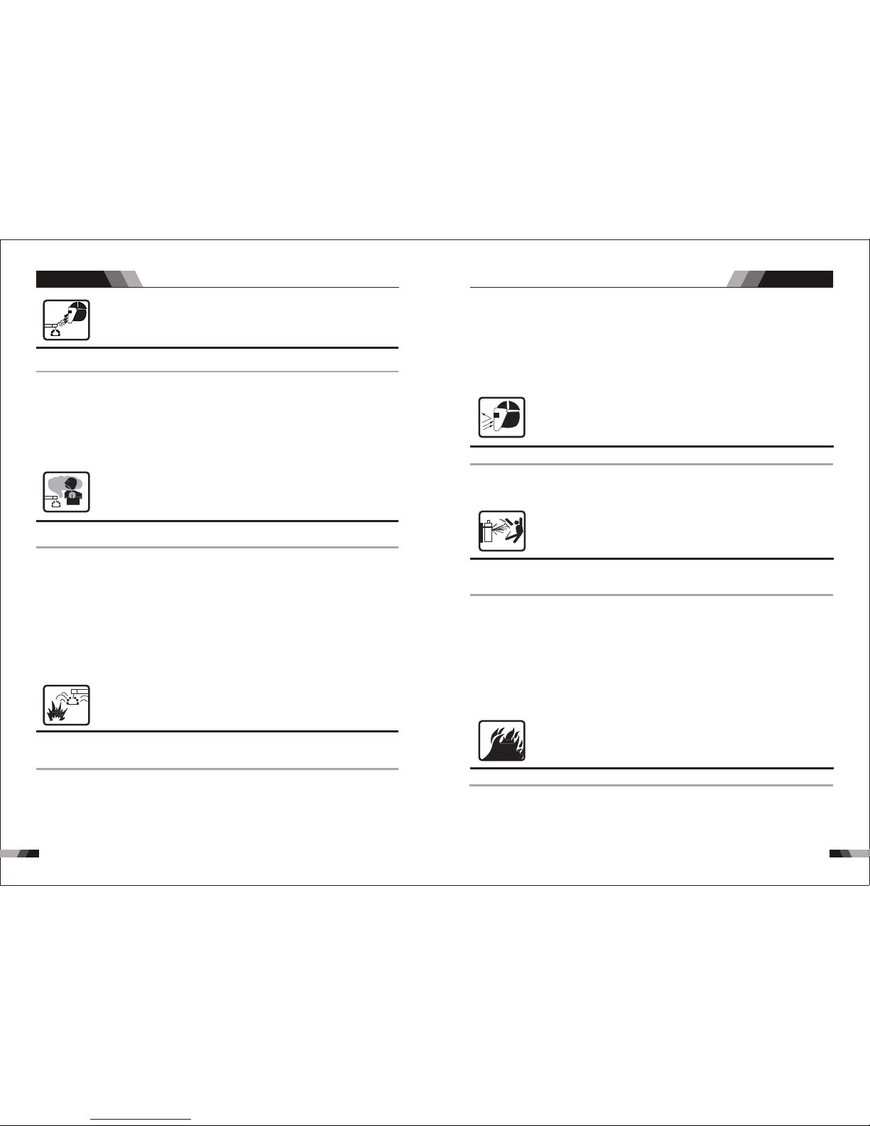
FLYI NG S PARK S an d HO T ME TAL
can c ause in ju ry.
Chi pping a nd grin ding caus e fl yi ng m et al . As we ld s co ol , th ey c an t hr ow o ff sl ag .
1. W ea r ap pr oved face s hield o r safet y goggl es. Sid e shiel ds reco mmend ed.
2. W ea r pr op er body pro tecti on to pro tect sk in .
WAR NI N G
ARC R AYS ca n bu rn e ye s an d sk in ,
NOI SE can da mage he aring .
Arc ra ys f ro m th e weldi ng p ro ce ss p ro duce in te ns e he at a nd st ro ng u lt ra vi olet ra ys t ha t
can b urn eye s and ski n. Nois e from so me proc esses c an dama ge hear ing.
1. W ea r a we ld ing helme t fitte d with a pr oper sh ade of fi lter to p rotec t your fa ce a nd e ye s
whe n weldi ng or wat ching ;
2. W ea r ap pr oved safe ty glas ses. Si de shie lds rec ommen ded;
3. U se p ro te ct iv e sc re en s or b arriers t o prote ct othe rs from f lash an d glare ;
war n other s not to wa tch the a rc ;
4. W ea r pr otective cl othin g made fr om dura ble, fl ame-r esist an t ma te ri al (w oo l an d le at he r)
and f oot pro tecti on;
5. U se a pp ro ve d ea r pl ug s or e ar m uff s if n oi se l ev el i s hi gh ;
6. N ev er w ea r co nt ac t le ns es w hile weldin g.
WAR NI N G
FUM ES AND GA SE S ca n be h azardou s
to yo ur heal th.
Wel di ng p ro du ce s fu me s an d ga se s. Breathin g th es e fu me s an d ga se s ca n be h az ar do us
to yo ur heal th.
1. K ee p yo ur h ea d ou t of t he f um es . Do not brea the the f umes.
2. I f in si de , ve nt il at e th e ar ea and/or u se exha ust at th e arc to re move we lding f umes
and g ases.
3. I f ve nt il at io n is p oo r, us e an a pproved a ir-supp li ed r es pi ra to r.
4. W or k in a c on fined spa ce only i f it is wel l venti lated , or whil e weari ng an air -supp lied
res pirat or. Shie lding g ases us ed for we lding c an disp lace ai r causi ng injury o r de at h.
Be su re the br eathi ng air is s afe.
5. D o no t we ld i n lo ca ti on s ne ar d egreasing , clean ing, or s prayi ng oper ation s. The he at
and r ays of th e arc can r ea ct w it h va po ur s to f or m hi gh ly t ox ic a nd i rr it ating gas es.
6. D o no t we ld o n co at ed m et al s, s uch as galv anized, l ea d, o r ca dm iu m pl at ed s te el , un le ss
the c oatin g is remo ved fro m the wel d area, t he area i s well ve ntila ted, an d if nece ssary,
whi le wear ing an ai r- supp lied re spira tor. The c oa ti ng s an d an y me ta ls c on ta in ing these
ele ments c an give o ff toxi c fu me s if w el de d.
WAR NI N G
WEL DING ca n cause f ire or ex pl os io n.
Spa rks and s patte r fly off f ro m th e we ld in g ar c. Th e fl y sp ar ks a nd h ot m et al , we ld s pa tt er,
hot w orkpi ece, an d hot equ ipmen t can cau se fire s and bur ns. Acci denta l conta ct of
ele ctrod e or weld ing wir e to meta l objec ts can ca use spa rks, ov erhea ting, o r fire.
1. P ro te ct y ou rs el f an d ot he rs from fly ing spa rks and h ot meta l.
2. D o no t we ld w he re f ly in g sp ar ks can stri ke flam mable m ateri al.
3. R em ov e al l fl am ma bl es f ar a way from th e welding a rc . If t hi s is n ot p os si bl e, t ig ht ly
cov er them w ith app roved c overs .
4. B e al er t th at w el di ng s pa rk s and hot mat erial s from we lding c an easi ly go thr ough smal l
cra cks and o penin gs to adj acent a reas.
5. Wa tc h fo r fi re , an d ke ep a f ir e ex ti ng ui sh er n ea rby.
WAR NI N G
CYL INDER S can exp lode if d am ag ed .
Shi eldin g gas cyl inder s conta in gas un der high pr es su re . If d am ag ed , a cy li nd er c an
exp lode. S ince ga s cylin ders ar e norma lly par t of the we lding p rocess, b e su re t o tr ea t
the m caref ully.
1. P ro te ct c om pr es se d ga s cy linders f rom exc essiv e heat, m echan ical sh ocks, a nd arcs .
2. I ns ta ll a nd s ec ur e cy li nd ers in an uprig ht p os it io n by c ha in in g th em t o a st at io na ry s up port
or eq uipme nt cyli nder ra ck to pre vent fa lling o r tippi ng.
3. K ee p cy li nd er s aw ay f ro m an y welding or ot he r el ec tr ic al c ir cu it s.
4. N ev er a ll ow a w el di ng e le ct rode to touch a ny c yl in de r.
5. U se o nl y co rr ec t sh ie ld in g gas cylin ders, reg ul at or s, h os es , an d fi tt in gs d es ig ne d fo r th e
spe cific a pplic ation ; maint ain the m and ass ociat ed part s in good c ondit ion.
6. Tu rn f ac e aw ay f ro m va lv e ou tl et when ope ning cyli nd er v al ve .
7. K ee p pr ot ec ti ve c ap i n pl ac e over valv e excep t when cy linder is i n us e or c on ne ct ed
for u se.
8. R ea d an d fo ll ow i ns tr uc ti ons on compre ss ed g as c yl in de rs , as so ci at ed e qu ip me nt .
WAR NI N G
ENG INE FUE L can c ause fi re o r ex pl os io n.
Eng ine fue l is high ly flam mable .
1. S to p en gi ne b ef or e ch ec ki ng or adding fu el .
2. D o no t ad d fu el w hi le s mo ki ng o r if unit is near a ny s pa rk s or o pe n fl am es .
3. Al lo w en gi ne t o co ol b ef or e fu elling. If po ss ib le ,c he ck a nd a dd f ue l to c ol d en gi ne b ef or e
beg innin g job.
4. D o no t ov er fi ll t an k — al lo w ro om for fuel t o expan d.
5. D o no t sp il l fu el . If f ue ll in g is spille d, clea n up befo re star ting en gine.
6. B e aw ar e th at w el di ng o n a ce il ing, floor, bu lkhea d, or par titio n can cau se fire o n the
hid den sid e.
7. D o no t we ld o n cl os ed c on ta in ers such as tan ks o r dr um s.
8. C on ne ct w or k ca bl e to t he w or k as close to t he weld ing are a as prac tical t o preve nt
wel ding cu rrent f rom tra velli ng long , possi bly unk nown pa ths and c ausin g elect ric
sho ck and fi re haza rds.
9. D o no t us e we ld er t o th aw f ro ze n pipes.
10. Rem ov e st ic k electro de from h older or cu t of f we ld in g wi re a t co nt ac t tip when not
in us e.
0302
Saf ety in struc tions Saf ety in struc tions
AC/DC WIG SERIES EQUIPMENTAC/DC WIG SERIES EQUIPMENT
Page 5
WAR NI N G
SPARKS can cause battery gases to explode;
BATTERY ACID can burn eyes and skin.
Bat terie s conta in acid a nd gene rate ex plosi ve gase s.
1. Al wa ys w ea r a fa ce s hi el d wh en w orking on a bat tery.
2. S to p en gi ne b ef or e di sc on necting or co nn ec ti ng b at te ry c ab le s.
3. D o no t al lo w to ol s to c au se s pa rks when wo rking on a ba tt er y.
4. D o no t us e we ld er t o ch ar ge b at teries or j ump sta rt vehi cles.
5. O bs er ve c or re ct p ol ar it y (+ and –) on ba tteri es.
WAR NI N G
STEAM AND PRESSURIZED HOT COOLANT
can burn face, eyes, and skin.
The c oolan t in the ra diato r can be ve ry hot an d under p ressu re.
1. D o no t re mo ve r ad ia to r ca p wh en engine is ho t. Al lo w en gi ne to cool.
2. W ea r gl ov es and put a ra g over ca p area wh en remo ving ca p.
3. Al lo w pr es su re t o es ca pe b ef ore complet el y re mo vi ng c ap .
NO TE
To red uce mag ne ti c fi elds in t he w or kp lace, u se t he f ol low in g pr oc edure s.
1. K ee p ca bl es c lo se t og et he r by twisti ng or tap ing the m.
2. Ar ra ng e ca bl es t o on e si de a nd a way from the op er at or.
3. D o no t co il o r dr ap e ca bl e ar ou nd the body.
4. K ee p we ld in g Po we r So ur ce a nd cables as fa r aw ay f ro m bo dy a s pr ac ti ca l.
5. T he p eo pl e with hear t-pac emake r shoul d be away f rom the w eldin g area.
1.2 Effects Of Low Frequency Electric and M agn eti c Fie lds
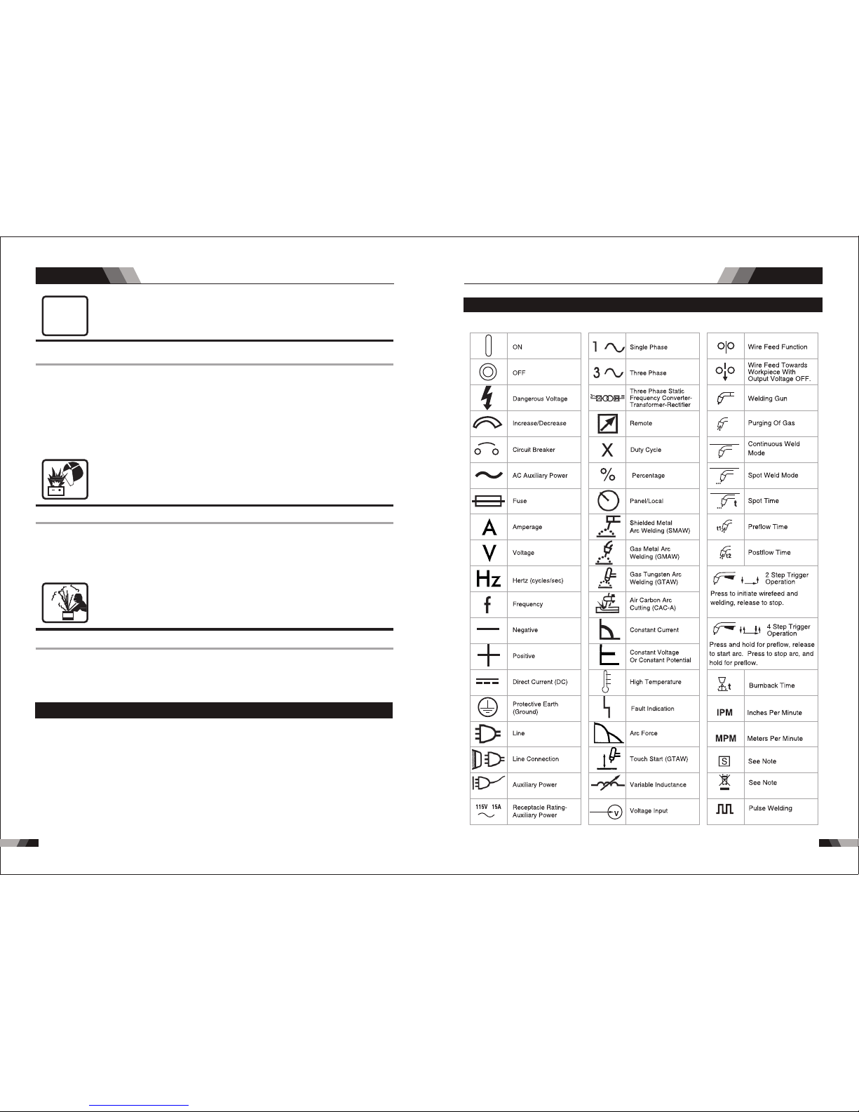
1.3 Sym bol Ch art
Note t ha t on ly s ome of th es e sy mb ols wil l ap pe ar o n you r mo de l.
Ele ctric c urren t flowi ng thro ugh any c onduc tor cau ses loc alize d Elect ric and M agnet ic
Fie lds (EM F). The d is cu ss o n th e effect of E MF i s on go in g al l th e wo rl d. U p to n ow, n o
ma te ria l evi de nce s sh ow th at EM F may h ave e ffec ts on h eal th. H oweve r, t he re searc h
on d am age o f EM F is stil l on goin g. Be fo re an y co nslu si on, we sh ou ld mi ni miz e ex pos ur e
to EM F as few as p ossib le.
WAR NI N G
MOVING PARTS can cause injury.
Mov ing par ts, suc h as fans , rotor s, and be lts can c ut f in ge rs a nd h an ds a nd c at ch l oo se
clo thing .
1. K ee p al l do or s, p an el s, c ov ers, and gu ards cl osed and se cu re ly i n pl ac e.
2. S to p en gi ne b ef or e in st al ling or conne cting u nit.
3. H av e on ly q ua li fi ed p eo pl e re move guar ds or cov ers for m ai nt en an ce a nd t ro ub le sh oo ti ng
as ne cessa ry.
4. To pr ev en t ac cidenta l start ing dur ing ser vicin g, disc onnec t negat ive (-) b atter y cable
fro m batte ry.
5. K ee p ha nd s, h ai r, lo os e cl ot hing, and too ls a wa y fr om m ov in g pa rt s.
6. R ei ns ta ll p an el s or g ua rd s and close doo rs when s ervic ing is fi nishe d and bef ore
sta rting e ngine .
0504
Saf ety in struc tions Sa fety in struc tions
AC/DC WIG SERIES EQUIPMENTAC/DC WIG SERIES EQUIPMENT
Page 6
0706
2.1 Bri ef Int roducti on
Sum marySum mary
TI G Lond on 24 00 AC/D C weld in g mach in e adop ts the late st p ul se wid th mod ul at io n
(P WM ) te ch no lo gy an d in su la ted ga te b ip olar t ra ns is tor (I GB T) p ower m od ul e, wh ic h ca n
ch an ge w or k fr eq ue ncy to m ed iu m fr eq uenc y so a s to r ep la ce the t ra di ti on al hul ki ng w or k
fr eq ue nc y t ra ns fo rm er wi th th e cab in et me di um f requ en cy tr an sf or me r. T hu s, it s ch arac te ri ze d wi th p or ta ble, s ma ll s iz e, l ight w ei gh t, l ow c onsu mp ti on a nd e tc .
T he p arame ter s of TIG Lo ndo n24 00 AC/D C on the fr ont panel all can be adj usted con tin uou sly a nd st epl es sly, su ch as star t cur ren t, cr ate r arc c urr ent, weldi ng cu rre nt, b ase c urren t, du ty r ati o, upsl ope t ime , do wns lop e time, p re- gas , po st- gas , pulse f req uen cy, AC freque ncy, balanc e, hot s tart, arc for ce et c. When wel ding, it ta ke s hig h fre que nc y and high
vol tag e for a rc ig nit ing t o ens ure t he su cce ss ra tio of ign iti ng ar c.
TIG L ondon 24 00 A C/ DC Charac teris tics:
◆MCU c ontro l syste m, resp onds im me di at el y to a ny c ha ng es .
◆Hi gh fr equ en cy an d hig h vol tag e for ar c ign iti ng to en sur e t h e s uc ces s r a ti o of
ign it ing a rc , th e rev er se pola ri ty igni ti on ensu re s good ig ni tio n be ha vio r in T IG -AC
wel ding.
◆Avo id AC a rc -b re ak w it h sp ec ia l me ans, even i f ar c- br ea k oc cu rs t he H F wi ll k ee p
the a rc stab le.
◆Ped al cont rol the w el di ng c ur re nt .
◆In D C TI G wit ho ut H Fo pert at ion , If t he tu ng st en e lect ro de to uc he s t he w or kp iece
wh e n we ldin g, th e cu rre nt w i ll d rop t o sh ort- cir cu it cu rre nt to p rote ct tu ng sten .
◆
occ ou red , th e al arm l am p on th e fr on t pan el w ill b e on a nd th e ou tput cu rr ent wil l
be cu t off. It c an self -p ro tec t an d pro lo ng t he us in g life.
◆Do ub l e p ur pos es : A C i nv e r t er T I G / M M A a n d D C in v e r t e r T IG/ MM A , E xc ell en t
per forma nce on AL -a ll oy, ca rb on s te el , st ai nl es s st ee l, t it an ium.
Acco rd in g to c hoosi ng t he f ro nt pane l fu nc tions , th e fo ll owing f iv e we lding w ay s
can be r ea li ze d.
DC MMA
DC TI G
DC Pul se TIG
AC TI G
AC Pul se TIG
In tel l ig ent pr ote cti o n: o ve r-c urr e nt , ov er -he at, w hen th e ment ion e d p rob lem s
1. Fo r DC MMA, p olari ty conn ectio n can be ch osen ac cordi ng to dif fe re nt e le ct ro de s;
2. F or DC T IG, D CEP i s u se d nor mal ly (w ork p ie ce co n ne cte d t o p os iti ve po lar it y, whi le
t orc h co n ne cte d to n ega tiv e po l ar ity) . Th is c on nec tion has man y ch a ra cte rs, s uch
a s st able w eldin g arc , low tung st en p ole l os s, m ore w elding c urre nt , na rrow a nd
dee p weld;
3. Fo r AC TIG ( recta ng le w av e) , ar c is m or e st ab le t ha n Si ne AC TI G. At the sa me time ,
you c an not on ly obta in the ma x penet ratio n and the m in tung sten po le loss , but als o
obt ain bet ter cle aranc e effec t;
4. DC P ulsed T IG h as t he f ol lo wi ng c ha ra ct ers:
1) P ul se h ea ti ng . Me ta l in M ol ten po ol h as s ho rt t im e on h ig h temp er at ur e st at us
an d fr ee ze s qu ic kl y, wh ic h ca n re du ce t he pos si bi li ty t o pr od uc e ho t crac k of t he
mat er ia ls w it h th er ma l se ns it iv it y .
2) Th e wo rkpi ec e ge ts l it tl e he at . Arc e nerg y is f oc us ed . Be s ui ta bl e for th in s he et
and s uper th in s he et w el di ng .
3) Ex actly c ontro l heat in put and t he size o f the mol te n po ol . Th e de pt h of p en et ra tion
is ev en . Be s ui ta bl e fo r we ld in g by o ne s id e an d fo rm in g by two sides an d all pos ition
wel ding fo r pipe.
4) H ig h fr eque nc y arc c an m ak e meta l fo r micr ol it e fabr ic , elim in at e blow ho le and
imp rove th e me ch an ic al p er fo rm an ce o f th e jo in t.
5) Hi gh freq uency a rc is sui table f or high w eldin g speed t o impro ve the pr oduct ivity.
TI G Lo nd on2 40 0 AC/ DC – ser ie s we lding mac hi nes is s ui tab le f or all pos it ion s w eld in g
for v ari ou s pla tes mad e of st ain le ss st ee l, ca rbo n st eel , alloy ed st ee l, ti taniu m, ma gn esi um ,
cup rum, etc , W hi ch is also app li ed to pip e ins tallm ent, mou ld me nd, petro che mi cal , arc hitec ture, d eco ra tio n, car re pai r, bic yc le, h an dic ra ft an d com mo n man ufact ure.
MMA ----- --Man ual Met al Arc Wel di ng
PWM ----- --Pul se-Wi dth Mod ulati on
IGB T----- ---In sulat ion Gat e Bi po la r Tra ns is to r
TIG -- -- -- -- -- Tun gs te n In se rt G as Weld ing
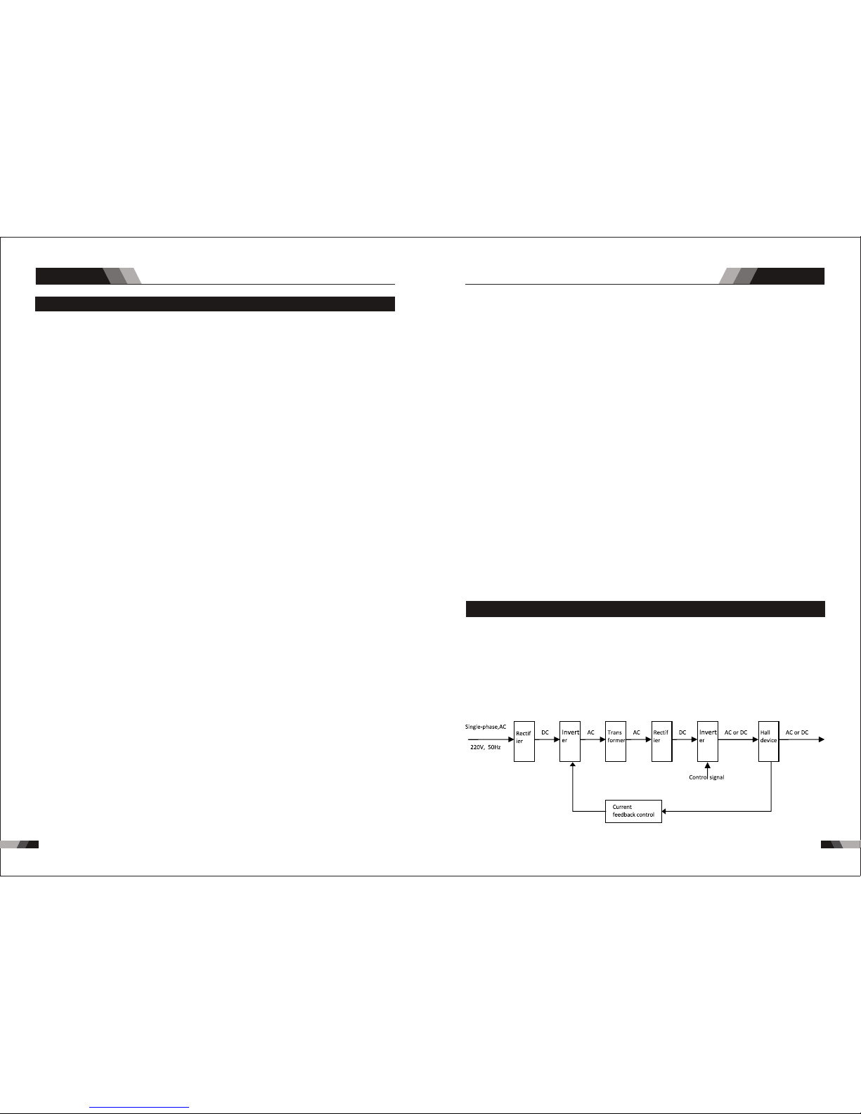
2.2 Wo rkin g Principle
The wo rkin g princi ple o f London 240 0 wel ding mac hine s is s how n as th e follow ing f igu re.
Sing le- phas e 2 30V work frequ enc y AC is rec tif ied int o D C ( abo ut 312 V), th en is con ver ted
to med ium f requ enc y AC (abo ut 20 -40 KHz ) by inv ert er de vice ( IGB T modu le) , afte r red ucing
volt age by med ium transfo rmer ( the main trans for mer) and re cti fyi ng by med ium frequen cy
rect ifi er (fa st recove ry diodes) , then is ou tpu tte d DC or AC by selecti ng IGB T modu le. The
circ uit ad opt s curr ent fe edba ck con tro l tech nology to in sure current output stabl y. Meanw hile,
the weld ing cur rent parame ter can be a dju sted contin uou sly and steples sly to m eet wit h th e
requ ire ment s of wel ding c raft .
AC/DC WIG SERIES EQUIPMENTAC/DC WIG SERIES EQUIPMENT
Page 7
0908
Sum mary
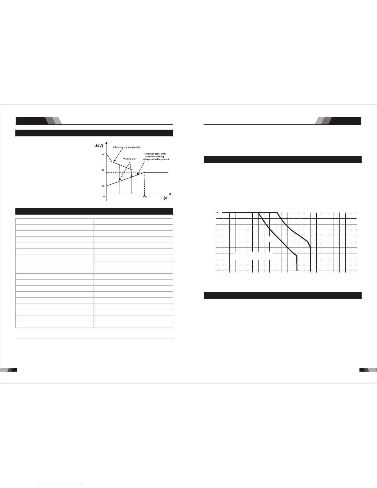
2.3 Vol t- Amper e Charact eris tic
Whe n I ≤600A , U =10 +0.04 I (V) ;
2 2 2
Whe n I >60 0A,U =34 (V).
2 2
TI G Lo nd on 24 00 A C/ D C we ld in g
mac hi ne h as a n ex ce ll en t vo lt-am pe re
cha ra ct er is tic , wh os e gr ap h is sh ow n
as the f ol lowin g f ig ure . T he re la ti on
bet we en th e conve nt io na l rated loa din g v ol tage U an d t he co nv ent io na l
2
wel di ng c ur rent I i s as f ol lo ws:
2
2.4 Spe cifi cations
170 A @ 25% , 26 .8V / 8 5A @ 100%, 2 3.4V
200 A @ 40% , 18 V / 126 A @ 100 %, 15 V
9.8 8 kg
10 - 17 0A
10 - 20 0A
15. 4A
30. 9A
10K VA
H36 0mmxW 160mm xD380 mm
Des cript ion
Wei gh t
Pow er Sour ce Dime nsion s
Coo ling
Wel de r Type
Eur opean S tanda rds
Num ber of Ph ases
Nom inal Su pply Vol tage
Nom inal Su pply Fr equen cy
Wel di ng Cu rrent R ange (M MA Mode)
Wel di ng Cu rrent R ange (T IG Mode )
Sin gle Pha se Gene rator R equir ement
MMA We ld ing O utput , 40ºC, 1 0 min.
TIG W el din g Outpu t, 40ºC , 10 min.
Ope n circu it volt age (MM A/TIG )
Pro tecti on Clas s
Max imum In put Cur rent
Effective Input Current
SIW M DIGITA L Lon don 2400
Fan C ooled
EN 60 974-1 / I EC 6097 4-1
1
230 V +/- 15%
50/ 60Hz
60V D C
IP2 3
Inv erter P ower So urce
Not e 3: Moto r start f us es o r th er ma l ci rc ui t br ea ke rs a re r ec om me nded for th is appl icati on.
Che ck l oc al r eq ui re me nt s fo r yo ur s it ua ti on i n th is regard .
Not e 1: The Ef fe ct iv e Input Curre nt s ho ul d be u se d fo r th e de te rm in at io n of c ab le s ize &
sup pl y re qu ir em en ts .
Not e 2: Gene rator R equir ement s at the Ma ximum O utput D uty Cyc le .
NOTE
Due t o varia tions t hat can o ccur in m anufa cture d produ cts, cl ai me d pe rf or ma nc e, v ol ta ge s,
rat ings, a ll capa citie s, meas ureme nts, di mensi ons and w eight s quote d are app roxim ate
onl y. Achi evabl e capac ities a nd rati ngs in us e and ope ratio n will depe nd u po n co rr ec t
ins talla tion, u se, app licat ions, m ainte nance a nd serv ice.
2.5 Dut y Cycl e
The r ate d du ty c ycl e of a We ld in g Power S ou rc e, is a s ta temen t of t he ti me i t ma y be
ope ra te d at it s ra te d weldi ng c ur ren t ou tp ut with ou t ex ceedi ng t he t emp er at ur e lim it s of
th e insu lat ion o f th e c o mp one nt par ts. To ex pla in th e 10 m inu t e d u ty cy cle pe rio d th e
fo ll owi ng e xamp le is u s ed . S up p os e a W el d in g P ow e r So urce is d esi gn ed to o per at e a t
a 5 0% du ty c yc le, 20 0 am pe res at 28 vo lts . Thi s me an s that it ha s be en de sig ned an d
bu ilt t o prov ide t he rat ed am per age ( 200 A ) f or 5 m i nu tes , i .e. a rc we ldi ng ti me, ou t of
ev er y 10 mi n ut e p er iod ( 50 % o f 10 mi nutes i s 5 m i nu tes ). Du r in g t he o the r 5 m in ute s o f
th e 10 mi nut e p e ri od th e Wel d in g Pow er So urc e m u st id le an d be all owe d t o c oo l. Th e
the rmal cu t out wil l opera te if the d uty cyc le is exc eeded .
Duty Cyc le (P ER CE NTAGE )
Weldin g Curre nt( AM PS)
◆2.5 m Power c able
◆200 Am p Elect rode Ho lder Wi th 2.5m c able
◆200 Am p Earth C lamp Wi th 2.5m c able
◆4m TI G Torc h WP -1 7
◆4m TI G Torc h WP -1 7
◆3m Ga s Hose
◆Ope ratin g Manua l
2.6 Pac kage d Items
2525
5050
7575
100100 12 512 5 150150 175175
00
101 0
202 0
303 0
404 0
505 0
606 0
707 0
808 0
909 0
10 01 00
20 0 225 250 27527500
Saf e Opera ting Re gion
(TI G&STI CK)
300
MM A
TIG
Sum mary
AC/DC WIG SERIES EQUIPMENTAC/DC WIG SERIES EQUIPMENT
Page 8
10
11
Ope ratio n
Ope ratio n
Behind
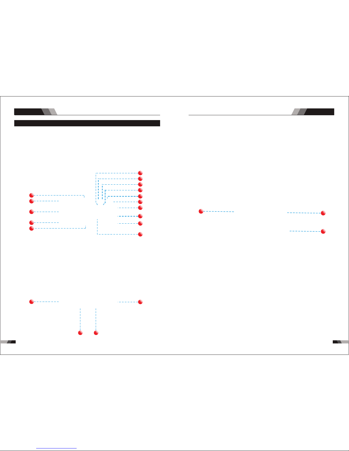
3.1 Lay out Fo r The Panel
Front
11
10
93
92
4
12
13
14
15
95
17
916
18 19
9
8
7
6
91
4
20
22
21
AC/DC WIG SERIES EQUIPMENTAC/DC WIG SERIES EQUIPMENT
Page 9
12
13
Ope ratio n
Ope ratio n
Min imum
Cur rent
Pre ss & hold
Trig ger
Rel ease
Trig ger
No te: t hat w hen o per a ti ng in GTA W ( HF and LI FT TI G m od es) , t h e p ow er so urc e w i ll
rem ain act ivate d until t he sele cted do wn slop e time ha s elaps ed
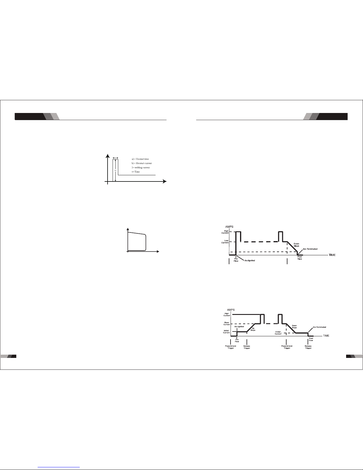
4T L at ch mo de t his m od e of we ld ing i s mai nl y use d for l ong w el din g r un s t o re duc e
op er ato r fa tigu e. In t his m o de t he op er a to r c an p res s an d rel ea s e th e tor ch t rig ge r a nd
th e o ut put w i ll r emai n act iv e. To dea ctiv ate t he po we r sou rc e, th e tr igg er s witc h mus t
ag ai n be pr ess ed an d r el e as ed, t h us e limi nat in g t he n eed f or th e o pe rat or to h old t he
to rc h tri gg er.
12. Trigger Mode Contro l Bu tt on ( HF T IG a nd L IF T TI G Mo de o nl y)
The t ri gg er m ode con tr ol i s us ed to s wi tc h th e fu nct io na li ty o f the tor ch t ri gg er betw ee n
2T an d 4T.
out pu t to b e ac ti ve .
Pre ss a nd h ol d th e to rc h tr ig ge r to acti va te t he p ow er s ou rc e (w el d). Rel ease th e to rc h
tri gg er s wi tc h to c ea se w el di ng.
2T N o rm a l Mo de In t his m o de , the t o rc h tri gg er mu s t re mai n p re sse d fo r the w el d in g
9. Fre qu en cy I ndica to r (H z)
Fre qu en cy i ndica to r, wh en the se tt in g pr ogram m in p ul se freq ue nc y ,t his ind ic at or w ill
be on .
11. The rm al O ve rload I nd ic at or Ligh t
This w el din g po wer s ource i s pro te cte d by a se lf r ese tt ing t he rmo st at. T he in dicat or will
ill um ina te i f the dut y cy cle o f th e pow er s ou rce h as b een exc ee ded . Sh ou ld th e th ermal
ove rl oa d in di ca to r il lumin ate the o ut pu t of t he p ow er s ource w il l be d is ab le d. O nc e the
pow er s ou rc e co ol s do wn t hi s li gh t will go O FF a nd t he o ve r te mp er at ur e conditi on w il l
aut om at ic al ly rese t. N ot e th at t he main s po we r sw it ch shou ld r em ai n in t he on p os it io n
suc h th at t he f an c ontin ue s to o pe ra te t hu s all ow in g th e un it t o cool su ff ic ie nt ly. Do n ot
swi tch the u nit off s ho ul d a th er ma l ov er lo ad c on dition be p resen t.
10. Po we r ON I nd icato r
The POW ER ON in dic ator illu min ate s when t he ON/ OFF sw itc h is in th e ON positio n and
the c orrec t mains v ol ta ge i s pr es en t.
1. Dig it al Ammet er / P ar am eter me te r
The digi ta l Amme te r is us ed t o dis pl ay th e ac tual ou tp ut cu rr ent of th e pow er s ource . It is
als o used to d ispla y Param eters i n Progr ammin g Mode.
De pe nd in g on t he P ro gr ammi ng P ar am et er s el ec ted, t he s ta tu s in di ct or adj ac en t to t he
Amme ter wil l illum inate t o show th e units o f the pro gramm ing par amete r.
Whe n weldi ng, the Am meter w ill dis play ac tual we lding c urren t.
2. Hot S ta rt
Arc fo rc e Corre ct io n
Hot S tart Fu nctio n relia bly ign ites th e elect rode
and m elts pe rfect ly to ens ure the b est qua lity
eve n at the st art of th e se am . th is s ol ut io n ma ke s
lac k of fusi on and co ld weld s a thing o f the pas t
and s ignif icant ly redu ces wel d reinf orcem ent.
Adj ust the h ot star t curre nt here a nd the ti me here .
Dur ing the w eldin g proce ss, arc force p reven ts
t h e e le ct ro de s t i ck i ng i n t h e we ld po o l wi th
inc rease s in curr ent. th is make s it easi er to wel d
lar ge- dr op me lt ing e lec tr ode t ypes at low cu rre nt
str ength s with a sh ort arc i n parti cular.
I
t
Ant i-sti ck prev ents th e elect rode fr om a nn ea li ng .
If t he el ect ro de st ick s i n s pi te of t he ar cro rc e dev ice , t he
machine a ut o m a t i c a l l y s wi t c h e s o ve r t o th e minimum
cu rren t wi t h in a b out 1 s eco nd t o p rev en t t h e e l e ctr ode
f r o m o ve rh e a ti n g . I n o r d e r to e a s il y s ep ar a t e th e
e l e c t r od e a nd e l e c t ro d e h ol de r t o p r o t ec t t he w e l d e r.
Anti stick
Anti stick
U
I
3. JOB a nd S AVE
You ca n p re ss J OB to s el ec t the me mory r eco rd s th at you h ave s av ed be fo re f rom 1- 9.
For t he n ew s et ti ng o f pr es en t cu rr en t Amp s ,j us t pr es s SAVE .
4. Mod e Bu tt on
Pre ss t he M OD E bu tt on t o to gg le AC a nd D C ou tp ut i n LI FT TI G, H F TIG.
5. Cur re nt a dj ustin g bu tt on /func ti on s ch oos in g
Clo ck wi se r otate t o en la rge the c ur re nt , and a nt i- cl ockwi se r ot at e to re du ce t he c urr en t.
If y ou ne ed t o choo se dif fer en t p ro gr ammi ng pa ra mete rs (t he ei gh th ma rk ), pre ss the
bu tt on an d re leas e it to c ho os e diff ere nt f unct ion s.
7. Cur re nt I nd icato r
Whe n setti ng prog ramm in t he peak c urren t, base c urren t, endi ng curr ent and r em , this
cur rent in dicat or will b e on.
6. Ti me Indi ca to r (s )
Time i nd ic ato r , wh en sett in g pro gr am m in ga s pr e- flo w, up s lop e, d ow n slo pe a nd ga s
pos t- flow, th is indi ca to r wil l be o n.
8. Per ce nt ag e Indic at or (% )
Per centa ge indi cator, w hen set ting pr ogram m in puls e duty cy cle , thi s indic ator wi ll be
on .
AC/DC WIG SERIES EQUIPMENTAC/DC WIG SERIES EQUIPMENT
Page 10
14
15
Ope ratio n
Ope ratio n
CAUT ION
Lo o se w eld in g ter m in al co nne c ti ons c an ca use o v er h ea tin g and r esu lt in t he ma le pl ug
be i ng f use d i n the t erm in al.
22. Po we r sw it ch
befor e using the machine. Pull the switch to the closu re state of “AN” to operat e the
machi ne, and pu ll the swi tch to “AU S” after use. Turn off the power inpu t, and the ma chin e
will sto p opera ting .
21. Ga s in pu t po rt
The gas po rt is conn ected with th e gas valve outp ut port . After con nect ion, ch eck whethe r
ther e is gas leak age.
20. Pr og ra m do wnloa di ng p or t
Cha nge t he pr ogram d own loa di ng co nne ct ion p ort , and u se th e pla st ic co ver t o pre vent
the d ust f rom p oll ut ing a nd ox idi zi ng th e por t aft er us e.
19. 5 Pi n Co nt ro l Socke t
The 5 pi n recep ta cle i s used to c onn ec t a tri gg er sw it ch or r em ote c on tro l to the we lding
Pow er Sour ce circ ui tr y:
To make connec tion s, ali gn keyw ay, insert plug , and rot ate thread ed coll ar ful ly clockwi se.
1
2
3
4
5
9
11
6
7
8
13
12
10
3.2 Con trol P anel
.Gas P re -F lo w 1
Abs ol ut e se tting ran ge 0 .1 s to 5 s (0 .1 S in cr em en ts )
Thi s param eter op erate s in TIG mo de s on ly a nd i s us ed t o pr ov id e ga s to the weld z one
pri or to str iking t he arc, o nce the t or ch t ri gg er s wi tc h ha s be en p re ss ed . Thi s co nt ro l is
use d to dram atica lly red uce wel d poros ity at th e start o f a weld.
2.In it ia l Cu rrent
The m ain cur re nt S et ti ng r an ge 1 0A MP t o 20 0AMP
This para met er ope rat es in (4 T) TIG m ode s only a nd is us ed to se t the st art cu rre nt for TIG.
Th e St art Cu rren t rema ins on un ti l the t or ch t rigg er swi tch is re le ased a fter it h as be en
dep resse d.
No te : The m ax im um in it ial c urr en t ava il abl e wil l be li m it ed to t he set va l ue o f t he b ase
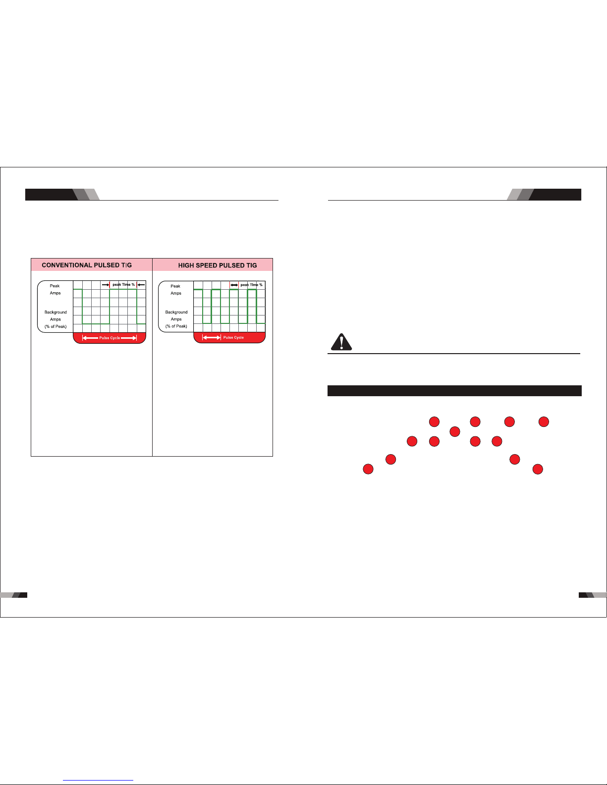
14. Puls e Bu tto n
Pre ss t he P UL SE b ut to n to t og gl e Pu ls e On a nd O FF.
Typi cally f rom 1 to 10 P PS. Pro vides a h eatin g
and c oolin g effec t on the we ld pudd le and ca n
red uce dis torti on by low ering t he aver age
amp erage . This he ating a nd cool ing effe ct also
pro duces a d istin ct ripp le patt ern in th e weld
bea d. The re latio nship b etwee n pulse f reque ncy
and t ravel s peed de termi nes the d istan ce
bet ween th e rippl es. Slo w pulsi ng can al so be
coo rdina ted wit h fille r metal a dditi on and
inc rease o veral l contr ol of the w eld pud dle
In ex cess of 4 0 PPS, Pu lsed TI G becom es more
aud ible th an visi ble-c ausin g incre ased pu ddle
agi tatio n for a bet ter as- welde d micro struc ture.
Pul sing th e weld cu rrent a t high sp eeds- betwe en
a hig h Peak an d a low Bac kgrou nd ampe ragecan a lso con stric t and foc us the ar c.Thi s resul ts
in ma ximum a rc stab ility, i ncrea sed pen etrat ion
and i ncrea sed tra vel spe eds(C ommon R ange:
100 -500 PP S).
The Ar c-Sha rpeni ng effe cts of hi gh spee d
pul sing ar e expan ded to ne w dimen sions . The
abi lity to p ulse at 5 ,000P PS furt her enh ances
arc s tabil ity and c oncen trati on pote ntial -whic h
is ex tre mel y benef icial t o autom ation w here
max imum tr avel ts peeds a re requ ired.
15. Pr og ra mm ing Par am et er I ndica to rs
The se i nd ic at or l ig ht s wi ll i ll uminate w hen progr am mi ng .
16. Po si ti ve W el di ng Term inal
Po sit iv e Wel di ng Term ina l. W eld in g c ur ren t f lo w s fro m t he Po w er S our ce vi a hea vy
du ty ba yon et ty pe te r mi n al s. It i s ess ent ia l, ho wev er , th at th e mal e p lug i s ins ert ed
and t ur ne d se cu re ly t o ac hi ev e a so un d el ec tr ic al c onnection .
and t ur ne d se cu re ly t o ac hi ev e a so un d el ec tr ic al c onnection .
17. Ne ga ti ve W el di ng Term inal
Ne ga tive We ld in g Ter mi na l. Wel ding cu rr e nt f low s fr om th e Po wer S ou rce v ia h eav y
du ty ba yon et ty pe te r mi nal s. It is es s en tia l, ho wev er , t ha t the m ale p lug i s ins e rt ed
18. Sh ie ld in g Gas Out le t
Th e Sh ie ldin g Gas O ut let l oc ate d on t he fro nt pan el is a f ast co nne ct io n of a su it ab le
TIG Tor ch .
AC/DC WIG SERIES EQUIPMENTAC/DC WIG SERIES EQUIPMENT
13. Pr oc es s Se lecti on B ut to n
The p roce ss s el ec ti on c ontr ol i s us ed t o se lect t he d es ir ed w el ding m od e. Tw o mo de s
are a vaila ble, GTAW ( TI G) , an d MM A (St ic k) m od es .
Page 11
16
17
Ope ratio n
Ope ratio n
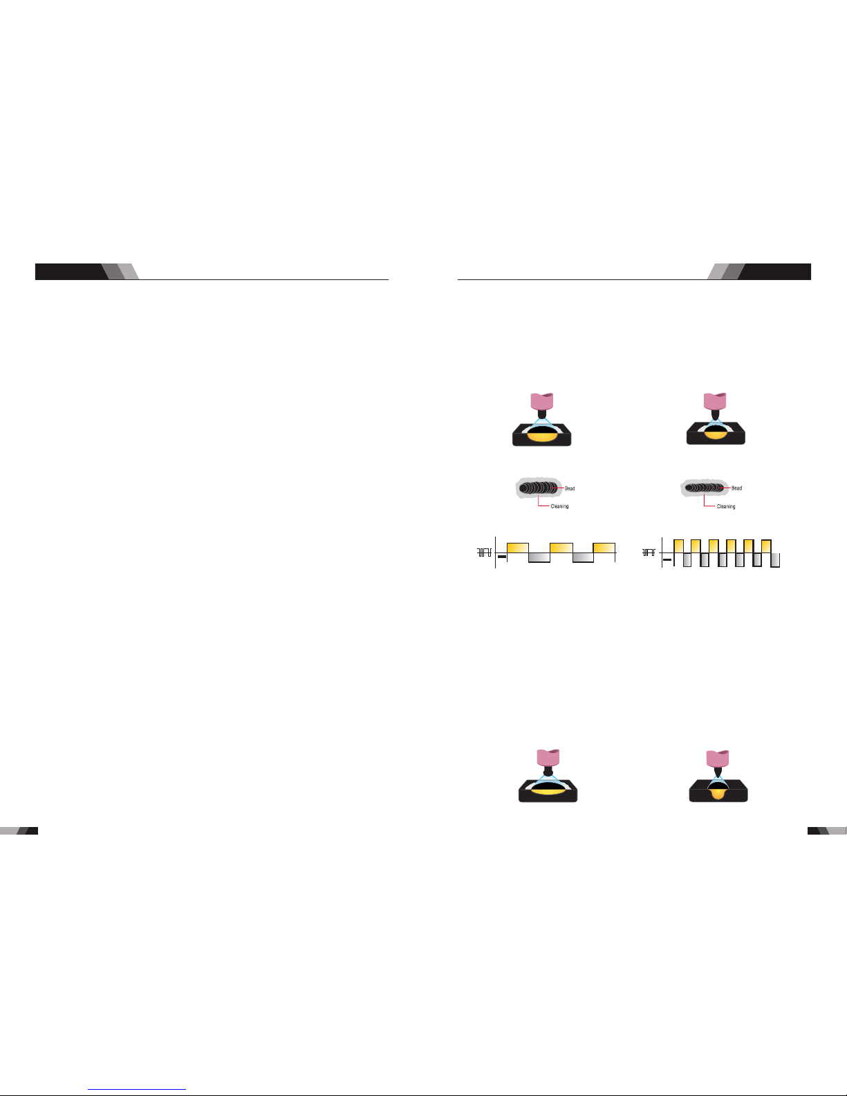
12.Wa ve B alanc e
Set ting ar range s 10%-3 0%
T h i s p ar am et e r o p e r at e s i n AC T I G mo de a n d i s u se d to se t t he p e ne t r a ti o n t o
cl ean ing ac tio n ra t io for the A C wel d cu r re nt. G en era lly WAV E BA LA NCE i s s e t t o
3 0 % f or A C S T IC K w e l di n g. T he WAV E BA L A N CE c on tr ol c h a ng e s th e r a ti o o f
pe ne tra ti on to c lea ni n g ac tion of t he AC TI G w el ding ar c. Ma xi m um w eld p en e tr ati on
i s a ch iev ed w he n th e WAVE BA LAN CE c on tro l is s e t t o 1 0 %. Ma xim um c le ani ng o f
h e a v il y o x i d is e d al um in iu m or m ag n es i um a ll oy s is ac h ie v ed w he n t h e W AVE
B A L A NC E c o n t ro l i s s et t o 3 0 %
Wid er bead , good pe netra tion
ide al for bu ildup w ork
Nar rower b ead for f illet w elds an d
aut omate d appli catio ns
Wid er bead a nd clea ning ac ting Nar rower b ead and c leani ng acti ng
AC Ba lance C ontro l
Co nt ro ls ar c cl eani ng ac ti on . Adj usti ng th e % EN o f the AC w av e co ntro ls th e wi dth of t he
etc hing zo ne surr oundi ng the we ld.
No t e : S e t the A C B al anc e con tro l f or ad equ a te ar c cle ani n g a ct ion a t the si des a nd in
fr ont o f t h e w e l d p u d dl e. AC B al an ce s ho ul d b e f ine tu ne d a c cor din g to h ow h e a vy o r
thi ck the ox ides ar e.
Wid er bead , good pe netra tion
ide al for bu ildup w ork
Nar rower B ead, Go od Pene trati on
Ide al For Bu ildup W or k
AC Fr equen cy cont rol
Con trols t he widt h of the ar c cone. I ncrea sing th e AC fr eq ue nc y provides a mo re f oc us ed
arc w ith inc rease d direc tiona l contr ol.
No te : D ecr ea s ing t h e AC F r e que nc y s oft en s t he a r c a nd b r o a de ns t he w eld p u ddl e
f o r a wi de r w eld b e a d.
11. AC F re qu ency
Set ting ra nges 50 HZ-20 0HZ
Th is p ar am eter o pe rate s in A C TI G mo de o nly an d is us ed t o se t the fr equ en cy f or th e
AC we ld curr ent.
3.Up S lo pe
Set ting ra nges :0 .1S-1 0S ( 0. 1S i nc re me nt s)
Thi s pa ramet er o pe rat es i n (2 T and 4 T) TI G mo des o nl y and is us ed t o set t he t ime for t he
we ld c urre nt to r am p up, a ft er the to rc h trigg er s witc h has b ee n p re ss ed the n relea se d ,
fro m Initi al Curr ent to Hi gh or bas e curre nt.
4.Pe ak C ur re nt
Set ting ra nges
10A MP to 200 AM P (D C TIG m od e) , 10 t o 20 0A (A C HF T IG m ode)
Th i s pa ram et er se ts th e TIG W ELD c u rr e nt . Thi s p ar a me ter a lso s ets t h e ST ICK w eld
cur rent.
5.Ba se C ur re nt
Set ting ra nges
10A MP to 200 AM P (D C TIG m od e) , 10 AM P to 2 00 AM P (AC H F TI G mo de )
Sec ondar y curre nt (TIG )/pul se paus e curre nt.
6.Do wn S lo pe
Set ting ra nges 0. 1-10s
Thi s pa ramet er o pe rat es i n TIG m od es only a nd i s use d to s et the ti me f or th e we ld c urr en t
to ramp down, after th e to rc h tr ig ge r sw it ch h as b ee n pr es se d to e nd c ur re nt . This control
is us ed to eli minat e the cra ter tha t can for m at the co mp le ti on o f a we ld .
7.En d cu rr en t
Set ting ra nges 10 A-200 A
This pa ram eter opera tes in (4 T) TIG mo des only and is us ed to set th e fini sh cur rent for TIG.
The en d Cur re nt re mai ns ON unti l the to rc h tri gge r swi tch i s rel eas ed af ter i t has been
dep resse d.
No te : The m ax i mu m c ra ter c u rr ent a v ai la ble w il l be li mi ted t o th e set v alu e o f th e bas e
cur re nt .
8.Po st F lo w
9. Rem ot e Co nt rol
Set ting ra nges 1- 10S
The s ystem i ndepe ndent ly iden tifie s the rem ote con trol, a nd when t he indi cator l ight is
on, t he weld ing cur rent ca n be adju sted by r emote ( foot or w eldin g gun).
Th is pa ram et er op er ate s in TI G m od es on ly an d is us ed to a dju st t he po st ga s flo w
ti me on ce th e a rc ha s e xt ing ui she d. T h is c ont ro l is us ed to d ram at i ca l ly r edu ce
ox ida tio n o f t he t ung st en el ect rod e.
10.P ul se W id th
Set ting ra nges 10 %-90%
Th is p ara mete r se ts t h e p e r ce nt age o n t ime o f t h e P ULS E FR E Q UEN CY f o r H igh
we ld cu rre n t whe n t h e P UL SE is O N.
11.Pu ls e Fr eq uency
Set ting ra ng es 1 HZ - 20 0H Z
Thi s param eter se ts t he P UL SE F RE QU EN CY w he n the PULSE is ON .
AC/DC WIG SERIES EQUIPMENTAC/DC WIG SERIES EQUIPMENT
Page 12
18
19
Ope ratio n
Ope ratio n
3.4 Set -up Fo r LIFT TIG (G TAW) Weldi ng
WAR NI N G
Bef ore any w eldin g is t o be gi n, b e su re t o we ar a ll
app ropri at e an d re co mm en de d sa fe ty e qu ip me nt .
4. Sl owly op en the Arg on Cyli nder Val ve t o th e fu ll y op en p os it io n.
5. Co nnect t he work l ead cla mp to you r work pi ece.
6. Th e tu ng st en m us t be g ro un d to a b lu nt point (s imila r to a penc il) in or der to ac hieve
opt imum we lding r esult s. See il lustr ation . It is cri ti ca l to g ri nd t he t un gs te n el ec tr od e
in th e direc tion th e grind ing whe el is tur ning. G rind at a 3 0 degre e angle a nd neve r
to a sh arp poi nt.
7. In stall t he tung sten wi th appr oxima tely 1. 6mm to 3. 2m m st ic ki ng o ut f ro m th e
gas c up, ens uring y ou have c orrec t sized c ollet .
8. Tig hten th e back ca p.
9. Tur n the swi tch to th e “ON” po sitio n. The po we r L. E. D. l ig ht s ho ul d il lu minate.
10. S et the we lding p roces s to LIFT T IG .
11. Se t th e We ld C urrent Cont rol Kno b to the de si re d am pe ra ge .
12. You are n ow r ea dy t o be gi n LI FT TI G We ld in g.
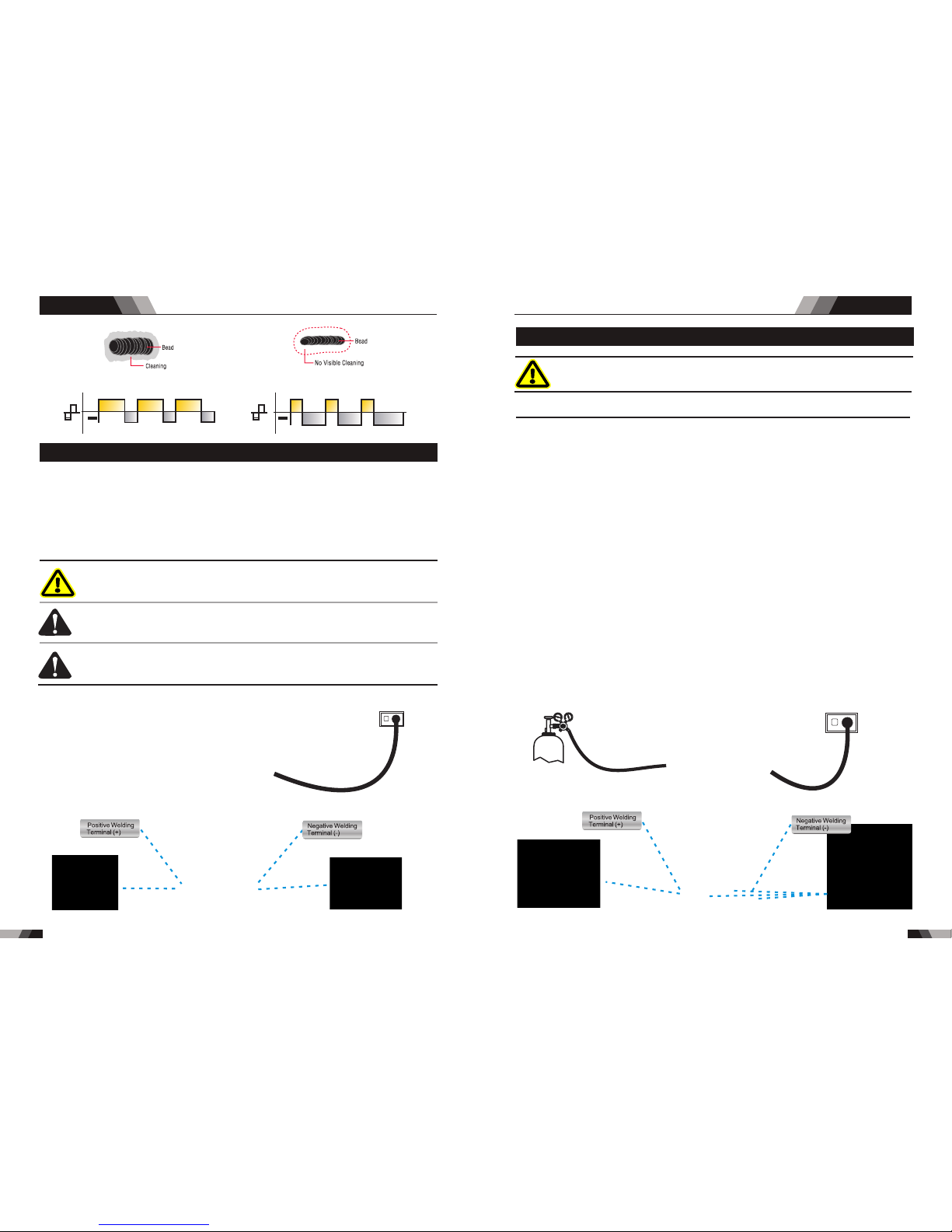
The f ollow ing set u p is know n as Stra ig ht P ol ar it y or D C el ec tr od e po si ti ve . Thi s is
com monly u sed for D C LIFT TI G we ld in g on most mater ia ls s uc h as s te el a nd s ta in le ss
ste el.
1. Sw itch th e ON/OF F Sw it ch ( lo ca te d on t he r ea r pa ne l) t o OF F.
2. Co nnect t he work l ead cab le to the p ositi ve outp ut term inal, a nd the LI FT TIG Torch
cab le to the n egati ve outp ut term inal.
3. Co nnect t he gas li ne/ho se to the p roper s hield ing gas s ource .
NO T E
Ar./ GAS(T IG/WI G)
power su pp ly
Ear th Clam p
TIG Tor ch
3.3 Set up For S TICK (MMA ) Wel ding
WAR NI N G
Be fo re c o nne ct in g th e wo r k c lam p to t he w ork a nd
in ser tin g t he el e ct r od e i n t he e lec tr ode h ol der m a ke
sur e the mai ns powe r su pp ly i s sw it ch ed o ff .
CA UT I ON
CA UT I ON
Re mov e a ny pa c ka g in g m at eri al pr i or t o use . D o not
bl ock t he ai r v en t s at th e fro nt or r ear o f t he We ld ing
Pow er Sour ce.
Lo os e w e l d in g te rmi na l c o n n ect io ns c a n c aus e
ov erh eat ing a nd re sul t i n t he mal e plu g bei ng fu sed
in th e bayon et t er mi na l.
Fo r Alka li ne Elec tr od e,co nn ec t th e ele ct ro de hol de r to th e posi ti ve we ld ing ter mi mal
El ec tr od e, pl ea se conn ec t th e el ec tr od e ho ld er to t he neg at iv e weld in g ter mima l and
ma nu fa ct ur er. W el di ng c urre nt f lo ws f rom th e Po we r Sou rc e vi a he av y dut y ba yo ne t ty pe
te rm in al s. I t is e ssen ti al , ho weve r, th at t he mal e pl ug i s inse rt ed a nd t urne d se cu re ly to
ac hi ev e a so un d elec tr ic al co nn ec ti on . Se lect S TI CK m ode wi th t he p roce ss s el ec ti on
co nt ro l.
a n d c o nn ec t t he w or k l ea d t o t h e n e ga ti ve we ld in g t er m i n al ,w hi l e f o r t h e Ac i d
co nne ct the wo rk le ad to th e pos itv e w e ld ing t erm i na l.I f in dou bt co nsu l t t he el ect r od e
Wid er bead a nd clea ning ac tion Nar rower b ead, wi th no vis ible cl eanin g
power su pp ly
Ear th Clam p
Ele ctrod e Holde r
AC/DC WIG SERIES EQUIPMENTAC/DC WIG SERIES EQUIPMENT
Page 13
21
20
Ope ratio n
Wel ding te chniq ue
TIG W eldin g App licat ion Sho t
4.1 TIG B asic Welding Techn ique
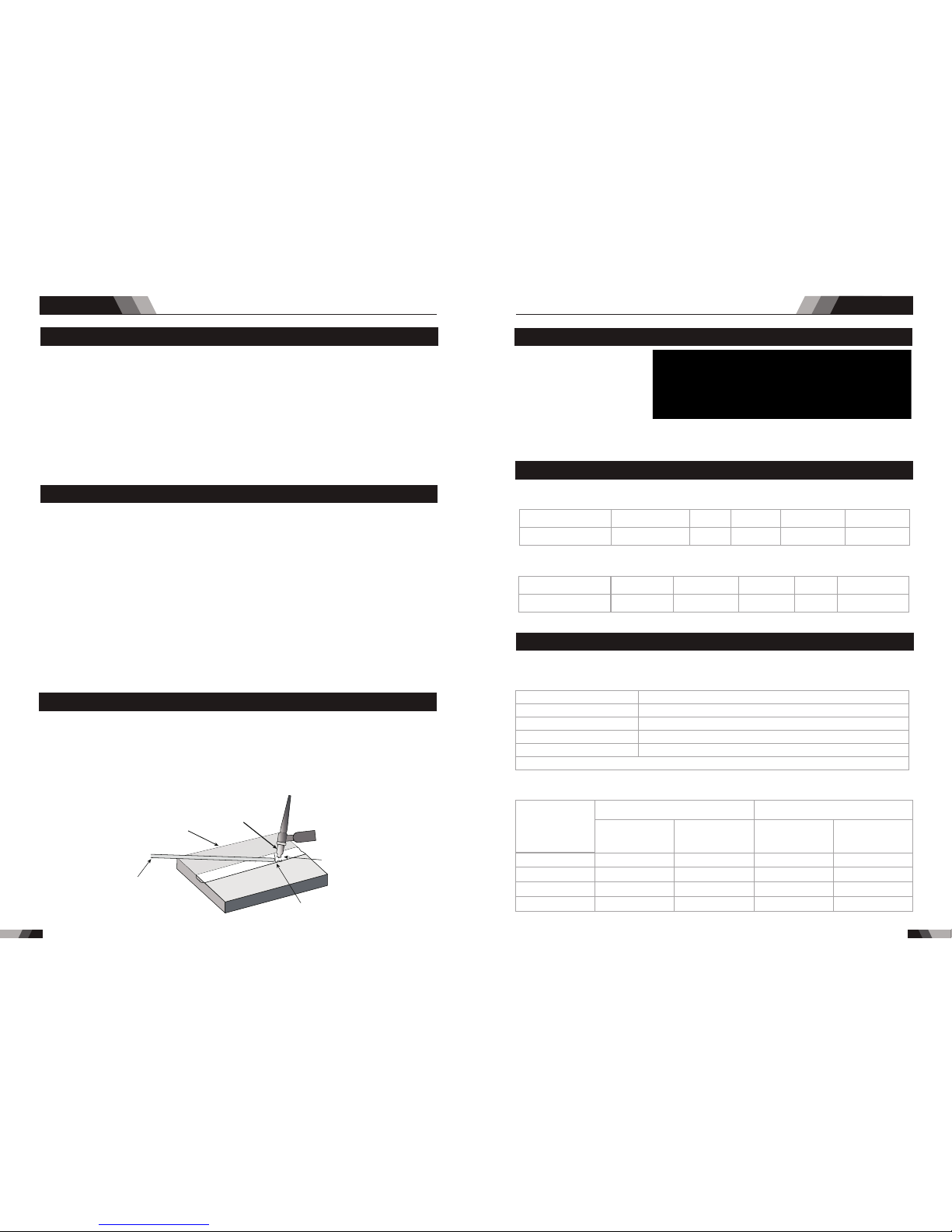
Gas Tu ngste n Arc We lding ( GTAW) or TI G (Tu ng st en I ne rt G as ) as i t is c om mo nl y re fe rr ed
to , is a we ldi ng p roce ss in w hi ch fu si on is p ro duc ed b y an el ec tri c ar c tha t is e stab lish ed
be tw ee n a sing le tun gste n (no n- c on suma ble ) el ec trod e a nd t he wo rk p ie ce. Sh ield in g is
obt ained f rom a wel ding gr ade shi elding ga s or w el di ng g ra de s hi el di ng g as m ix tu re w hi ch
is ge ner al ly Arg on ba se d. A fill er me tal may a lso b e add ed m anu al ly in s ome cir cum st ances
dep endin g on the we lding app li ca ti on .
Gas C up
Eit her Cer amic,
Hig h-lmp act or
Wate r Coole d
Met al
Work P iece
can B e Any C ommer cial
Met al
Weld s Made Wi th or
Wit hout Add ition
of Fi ller Me tal
Ine rt Gas
Shi elds El ectro de
and We ld Pudd le
Tung sten El ectro de
Non -Cons umabl e
3.6 Ope rati on Notice s
◆Height abo ve s ea l ev el i s be lo w 10 00 m.
◆Operatio n te mp er at ur e ra ng e: -1 0˚ C~ +4 0˚ C.
◆Relative h um id it y is b el ow 9 0% (2 0˚ C) .
◆Preferab ly s it e th e ma ch in e so me a ng le s ab ov e th e floor level ,t he m ax im um
angle does n ot e xc ee d 15 ˚.
◆The conten t of d us t, ac id ,c or ro si ve g as i n th e su rr ounding air o r su bs ta nc e
can not exce ed n or ma l st an da rd .
◆Take care that t he re i s su fficie nt v en ti la ti on d ur in g we ld in g. Th ere is at least
30cm free di ss ta nc e be tw ee n th e ma ch in e an d wa ll .
3.5 Ope rati on Enviro nmen t
◆Read safty i ns tr uc ti on a nd C ha pt er 1 c ar ef ul ly b efore attempt in g to u se t hi s
equipmen t.
◆Connect th e gr ou nd w ir e th e ma ch in e di re ct ly
◆In case clos in g th e po we r sw it ch , no -l oa d vo lt ag e may be export ed .D o no t to uc h
the output e le ct ro de w it h an y pa rt o f yo ur b od y.
◆Before ope ra ti on ,n o co nc er ne d pe op le s ho ul d be left,Do no t wa tc h th e ar c in
unprotec te d ey es .
◆Ensure goo d ve nt il at io n of t he m ac hi ne t o im pr ov e duty ratio.
◆Tur n off the en gi ne w he n th e op er at io n fi ni sh ed t o ec onomize ene rg y so ur ce .
◆When power s wi tc h sh ut s off pr ot ec ti ve ly b ec au se o f fa il ur e. Do n’ t restart it un ti l
until prob le m is r es ol ve d.
Otherwis e, th e ra ng e of p ro bl em w il l be e xt en de d.
4.4 TIG P aram eters Mat chin g
The co rr es po nding r el at io nship b et we en g as no zz le
diam et er a nd e lectr od e di am ete r
Gas n ozzle d iamet er/mm
6.4
8
9.5
11.1
Ele ctrod e diame ter/m m
0.5
1.0
1.6 o r 2.4
3.2
Not ice: th e above p arame ters or igina te from < <Weld in g Dic tiona ry>> P1 42,Vol ume 1 of Ed ition 2 .
04
Gas no zz le a nd t he shie ld g as f lo w rate
Welding
current range/A
DC positive connection
AC
Gas nozzle
diameter/mm
Gas flow
1
rate/L•min-
Gas nozzle
diameter/mm
Gas flow
1
rate/L•min-
10~100
101~150
151~200
201~300
4~9.5
4~9.5
6~13
8~13
4~5
4~7
6~8
8~9
8~9.5
9.5~11
11~13
13~16
6~8
7~10
7~10
8~15
Not ice: th e above p arame ters or igina te from < <Weld in g Dic tiona ry>> P1 49,Vol ume 1 of Ed ition 2 .
Pro tect ef fe ct
bes t bet ter
goo d
bad
wor st
Wel di ng a re a co lo r bri ght arg ent ora ng e- ye ll ow
blu e-pur ple
cae sious
whi te powd er
of ti taniu m oxid
The re la ti on o f weldi ng a re a co lor & pro te ct e ff ect o f Ti-a ll oy
4.3 The e xpla nation of w eldi ng qualit y
The re la ti on o f weldi ng a re a co lor & pro te ct e ff ect o f st ai nl ess ste el
Pro tect ef fe ct
bes t b et te r
goo d
bad
wor st
Wel di ng a re a co lo r arg ent,g olden
blu e
red -grey
gre y
bla ck
a butt j oin t b lap j oint c cone r joi nt d T join t
4.2 Joi nt fro ms in TIG
AC/DC WIG SERIES EQUIPMENTAC/DC WIG SERIES EQUIPMENT
Page 14
23
22
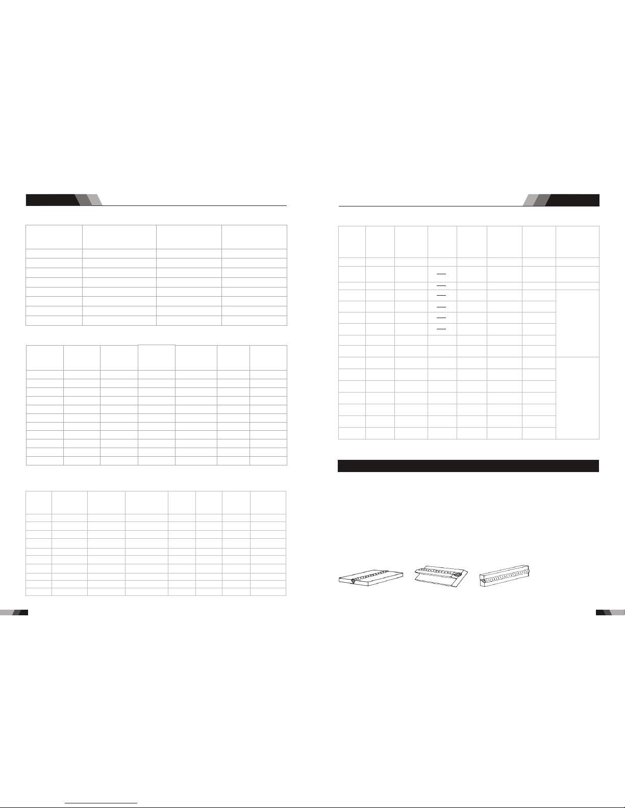
TIG o f stain le ss s te el (s in gl e ru n we ld in g)
Workpiece
thickness
/mm
Joint form
tungsten
electrode
diameter
/mm
welding
wire
diameter
/mm
Argon gas
flow rate/
1
L•min-
welding
current
(DCEP)
Weld ing
spee d/
cm•m in- 1
0.8
1.0
1.5
1.5
2.4
2.4
3.2
3.2
4.8
4.8
6.0
Butt joint
Butt joint
Butt joint
Corner joint
Butt joint
Corner joint
Butt joint
Corner joint
Butt joint
Corner joint
Butt joint
1.0
1.6
1.6
1.6
1.6
1.6
1.6
1.6
2.4
3.2
4.0
1.6
1.6
1.6
1.6
2.4
2.4
2.4
2.4
3.2
3.2
4.0
5
5
7
7
7
7
7
7
8
9
10-12
20~50
50~80
65~105
75~125
85~125
95~135
100~135
115~145
150~225
175~250
220~300
66
56
30
25
30
25
30
25
25
20
25
Not ice: th e above p arame ters or igina te from < <Weld in g Dic tiona ry>> P1 50,Vol ume 1 of Ed ition 2 .
Wel ding te chniq ueWel ding te chniq ue
Tungsten
Electrode
Diameter/mm
Sharpened of
the Electrode
Diameter/mm
Angle of Cone(º)
Background
Current/a
1.0
1.0
1.6
1.6
2.4
2.4
3.2
4.0
0.125
0.25
0.5
0.8
0.8
1.1
1.1
1.5
12
20
25
30
35
45
60
90
2~15
5~30
8~50
10~70
12~90
15~150
20~200
20~300
Tung sten El ec tr od e
Par amete rs of pip ing bac k se al in g we ld in g fo r mi ld s te el (D CE P)
Piping
diameter
Φ/mm
Tungsten
electrode
diameter/mm
Gas nozzle
diameter/mm
Welding
wire diameter/mm
Welding current/A
Welding
current/A
Arc
voltage/V
Argon flow
1
rate/L•min-
Welding
1
rate/cm•min-
38
42
60
76
108
133
159
219
273
325
2.0
2.0
2.0
2.5
2.5
2.5
2.5
2.5
2.5
2.5
8
8
8
8~10
8~10
8~10
8~10
8~10
8~10
8~10
2
2
2
2.5
2.5
2.5
2.5.
2.5
2.5
2.5
75~90
75~95
75~100
80~105
90~110
90~115
95~120
100~ 120
110~ 125
120~ 140
11~13
11~13
11~13
14~16
14~16
14~16
14~16
14~16
14~16
14~16
6~8
6~8
7~9
8~10
9~11
10~12
11~13
12~14
12~14
12~14
4~5
4~5
4~5
4~5
5~6
5~6
5~6
5~6
5~6
5~6
Not ice: th e above p arame ters or igina te from < <Weld in g Dic tiona ry>> P1 67, Volu me 1 of Edi tion 2.
Not ice: th e above p arame ters or igina te from《W el din g Dicti onary》P 538, Vol ume 2 of Ed ition 2 .
Para me te rs o f AC T IG (M MA ) for Al ui nu m and its a ll oy
Steet
thickness
/mm
Welding
wire
diameter
/mm
Tungsten
eletrode
diameter
/mm
Pre-heat
Temper
-ature/ºC
Welding
current/A
Argon flow
1
rate/L•min-
Gas nozzle
diameter
/mm
Remark
1.6
1.6~2.0
2~2.5
2~3
3
3~4
4
4~5
4~5
2
2
2~3
3
4
4
5
5
5
100
100~150
45~60
50~80
90~120
150~180
180~200
180~240
240~280
260~320
280~340
1
1.5
2
3
4
5
6
8
10
7~9
7~9
8~12
8~12
10~15
10~15
16~20
16~20
16~20
8
8
8~12
8~12
8~12
10~12
14~16
14~16
14~16
Flange welding
Flange or butt
welding by
one side
Butt welding
V-groove
butt welding
12
14
16
18
20
16~20
22~25
4~5
5~6
5~6
5~6
5~6
5~6
5~6
5~6
5~6
6
6
6
6
6~7
150~200
180~200
200~220
200~240
200~260
200~260
200~260
300~360
340~380
340~380
360~400
360~400
300~380
360~400
18~22
20~24
20~24
25~30
25~30
25~30
30~35
16~20
16~20
16~20
16~20
20~22
16~20
20~22
X-groove
butt welding
4.5 MMA Bas ic We lding Tec hniq ue
Arc Weld ing Pra cti ce
Th e tec h ni que s u s ed fo r arc we ldi ng ar e alm ost i den t ic al re gar dle ss of w hat t ype s o f
me ta l s ar e b ei ng jo in ed. Nat ur a ll y eno ug h , di ff e re nt ty pe s o f el ectr odes wo ul d b e us ed
for d iffer en t me ta ls a s de sc ri be d in t he p recedin g secti on.
Weldin g Posit ion
Th e el e ct rod es d e a lt w it h in t his p ub lic atio n ca n b e us ed i n m o st p os itio ns, i .e . th e y
ar e s ui tab le fo r wel di ng in f lat , h or izo nt al, v ert ica l a nd ov erh ea d pos iti o ns . N ume r ou s
ap p li cat io ns ca ll fo r wel ds to b e mad e i n p os iti on s int e rm edi at e bet w ee n t hes e . Som e
of th e commo n types o f welds a re show n
Fla t Posit ion,
Dow n Hand Bu tt Weld
Fla t Posit ion,
Gra vity Fi llet We ld
Hor izont al Posi tion,
But t Weld
Hor izont al-Ve rtica l
(H V) Posi tion
AC/DC WIG SERIES EQUIPMENTAC/DC WIG SERIES EQUIPMENT
Page 15
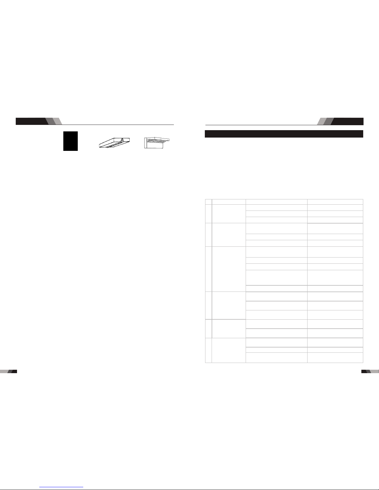
Vert ical Po sitio n,
But t Weld
Vert ical Po sitio n,
Fil let Wel d
Vert ical Po sitio n,
Fil let Wel d
Ove rhead P ositi on,
Fil let Wel d
Join t Prepa rat io ns
In m any c ase s, it w il l be po ss ible to w eld ste el se ct ions wi th out a ny s peci al pr ep ar ation .
For h eavie r secti on s and f or re pa ir wo rk o n cas ti ngs , etc., i t wil l be n ece ss ary t o cut or gr ind
an a ng le be tw een th e piec es bei ng joi ned to e nsur e prop er pen etra ti on of t he w el d meta l
and t o produ ce soun d joint s.
In ge neral , surfa ces bei ng weld ed shou ld be cle an and fr ee of rus t, scal e, dirt , greas e, etc.
Sla g shoul d be remo ved fro m oxy-c ut surf aces.
Arc Weld ing Tech ni que - A Wor d to Be gi nne rs
For thos e who have not yet done any we lding , the si mp les t way t o com men ce is t o run be ad s
on a pi ece of sc rap pla te. Use m ild ste el plat e about 6 .4mm (1 /4") th ick and a 3 .2mm (1 /8")
el ec tr od e. C le an a ny pai nt , lo os e scal e or g re as e off th e plat e an d se t it fi rm ly o n th e wo rk
ben ch s o tha t we ld ing can b e ca rri ed o ut in the d ow nhand p os it ion . Ma ke sure t ha t the wor k
cl am p i s ma kin g go od ele ctri cal co ntac t with th e wo rk, eit he r d ir ec tly or th ro ugh t he wo rk
ta bl e . Fo r l ig ht ga ug e mat er ia l, al wa ys cl am p the w or k l ea d d ir ec tly to th e j ob , o th er wise
a poo r circu it will p robab ly resu lt.
The Weld er
Pl ac e you rs e lf i n a com fo rtab le po si tion be for e b eg inn in g to we ld . Get a s eat o f su itab le
he ig ht an d do as m uch w or k as po ss ibl e si tting d o wn . D on ' t ho ld yo ur b ody t en se. A taut
at tit ude o f min d a nd a te nse d bo dy wi l l so on ma ke yo u fee l t ir ed. R el ax an d y ou wi ll fi nd
th a t the j ob be com es mu ch ea s ie r. You ca n add m uch t o you r pea c e of mi nd by w ear i ng
a lea the r a p ro n and ga unt let s . You wo n't be wo rry i ng th en abo ut be ing b urn t or s pa rks
set ting al ight to y our clo thes.
Pl ac e th e wo rk s o that t he d ir ec tion o f we ld in g is acr os s, r at her th an t o or f rom yo ur b od y.
Th e e le ctr od e hol d er l ead s hou ld b e cle ar of a ny ob st ruc ti on so t hat y o u can m ove y o ur
a rm f re ely alo ng a s t h e e lec tro de b ur ns d o wn . If t he l ea d is s lun g over yo ur s h ou lde r,
it all ow s gr ea te r fr ee do m of m ov em en t an d ta ke s a lot of w ei gh t of f yo ur h an d. B e su re t he
in s ul a ti on on y our c abl e a nd el ect ro de ho l de r is no t fau lty, o the rw ise y o u are r isk in g an
ele ctric s hock.
Wel ding te chniq ue
25
24
5.1 Trou bles hooting
◆Bef ore arc w eldin g machi nes are d ispat ched fr om the fa ctory, t he y ha ve a lr ea dy b ee n
deb ugged a ccura tely. So f or bi d an yo ne w ho i s no t au th or ized by us to d o any cha nge to
the e quipm ent!
◆Mai ntena nce cou rse mus t be oper ated ca reful ly. If any w ir e be co me s fl ex ib le o r is
mis place d, it may be pote ntial d anger t o user!
◆Onl y profe ssion al main tenan ce pers onal wh o is auth orize d by us cou ld overha ul t he
mac hine!
◆Gua rante e to shut o ff the ar c we ld in g ma ch in e’s p ower be fore tu rn on the o utlin e of
the e quipm ent!
◆If th ere is an y probl em and ha s no the au thori zed pro fessi onal ma inten ance pe rsona l,
ple ase con tact lo cal age nt or the b ranch c ompan y!
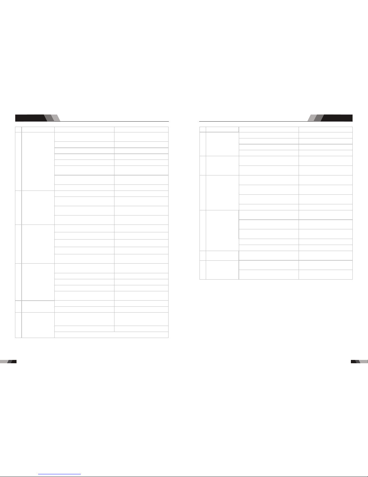
If th er e ar e so me s im pl e tr ou bl es o f we ld in g ma ch in e, you can cons ult the f ol lo wi ng
ove rhaul ing cha rt:
Nr.
1
2
3
4
5
Troubles
Solution
Fan is broken
The power board is broken
The power cable is broken
There is something in the fan
The start capacitor of fan damaged
Tur n on t he p ow er
sou rce, po wer
ind icato r is lit, f an
is no t worki ng.
Tur n on t he
pow er sour ce,
fan i s worki ng,
pow er indi cator
is no t lit
Tur n on t he p ow er
sou rce, fa n is not
wor king ,p ower
ind icato r is not li t
Tur n on t he p ow er
sou rce, po wer
ind icato r is lit, f an
is wo rking , there
is no w eldin g
out put.
The n umber o f the
dis play is n ot
int act
Reasons
Cha nge fan
Cle an it
Cha nge cap acito r
The p ower li ght dam aged or
con necti on is not g ood
The p ower ca ble con necte d not
goo d
Con trol bo ard is br oken
st
1 in verte r circu it dama ged
nd
2 f ee db ac k ci rc ui t is f au lt
Dig ital tu be is bro ken
The d ispla y panel i s damag ed
Cha nge the d ispla y panel
Display panel is broken
The light of the power indicator is
broken and the problems
mentioned in Nr. 2
Change the light of the power
indicator or refer to the solution
in Nr. 2
Cha nge it
Cha nge it
Cha nge it
Cha nge it
Rep air or ch ange it
Cha nge the p ower li ght
Con nect co rrect ly
Pow er on swi tch is da maged
The p ower bo ard is br oken
Cha nge it
Rep lace it
Cha nge it
Cha nge it
6
No no -load
vol tage ou tput
(MM A)
If th e overh eat ind icato r is on
The m ain cir cuit is b roken
The m achin e is brok en
Wait a few minutes, the machine
can b e opera ted nor mal
Che ck and re pair
Con sult th e deale r or the
man ufact urer
Tro ubles hooti ng
AC/DC WIG SERIES EQUIPMENTAC/DC WIG SERIES EQUIPMENT
Page 16
Tro ubles hooti ng
Tro ubles hooti ng
27
26
Nr.
7
8
9
10
11
Troubles
Solution
The welding cable is not connected
with the two output if the welder
Connect the welding cable to
the welder's output
The welding cable is damaged
The earth cable connected unstably
The welding cable is too long
Input voltage not stable
There is oil or dust on the workpiece
Gas cylinder is close or gas
pressure is low
The HF igniting board does not work
Something is in the valve
Check if the function selected MMA
Change the function to TIG
Check the HF funtion is selected Select the HF funtion
HF board is broken
Earth clamp connect not stable
Repair or change it
Check the earth clamp
Open or change the gas cylinder
Remove it
Remove it
Change it
Change it
Change it
The distance between discharger is
too short or too long
The malfunctio n of the welding gun
switch
No argon gas flow or the air tube
connect not good
No argon gas flow or the air tube
connect not good
Pressure too high or air regulator is
broken
There is no Argon flow or the
connectio n is poor
The distance between tungsten
electrode and workp iece is too long
Repair or change it
Check the earth cable
Use an appropriate welding cable
Check the power supply
Check and remove it
Reduce the distance
(about 3mm ,less than 5mm)
Check and reconnect
Repair or change it
Adjust the distance (about 0.8mm)
Check the welding torch switch,
control cable and aero socket.
Check and reconnect
Check and reconnect
Check gas
Arc c an not be
ign ited (T IG) ,
the re is spa rk
on th e HF
ign iting b oard
Arc c an not be
ign ited (T IG) ,
the re is no sp ark
on th e HF
ign iting b oard
Tur n on t he
pow er sour ce,
eve rythi ng is
nor mal , but n o
HF ig nitin g
No ga s flow (T IG)
Gas a lways f lows
Reasons
Elec trom agnetic va lve is da mage d
Air tub e is broc ken
Some thin g is in the val ve
Elec trom agnetic va lve is da mage d
Nr.
16
17
18
Troubles
Solution
Over-heat prot ection ,too much
welding curren t
Reduce the welding current
Reduce the welding time
Over-heat prot ection ,workin g too
much time
Over-curr ent protection, current in
the main circuit is out of control
Tig torch is connected to the
positive termi nal
Tungsten electrod e is too big for
the welding current
Check the earth clamp position on
the work piece
Check and repair main circuit
and drive board
Connect the tig torch to negative
terminal
Adjust the position of earth clamp
Select the correct size of tungsten
electrode
Thermal overload
indicator light is on
Tig electrode melts
when welding
Arc flutters during
Tig welding
Reasons
15
The p enetr ation
of mo lten po ol is
not e nough
Adj ust the d istan ce from t orch
to wo rk piec e
Use t he suit able le ngth fr om
man ufact urer
Inc rease t he weld ing cur rent
The w eldin g curre nt is adj usted
too l ow
The a rc is too l ong in th e weldi ng
pro cess
The p ower ca ble or th e weldi ng
cab le is too l ong
12
Checking if the electorde stick to
the work piece that the anti-stick
function is on
Repair or change it
Repair or change it
Change to suitable setting
The w eldin g
cur rent ca nnot
be ad juste d
Cont rol boa rd is bro ken
Cont rol boa rd is bro ken
AC Width adjustment is not correct
Shut off the powe r when ch angi ng the to rch
Sep arate t he elec trode a nd
wor k piece
13
14
Repair or change it
Check the power supply
Change the fan
Change it
Change it
No AC ou tput
whi le sele cting
"AC "
The w eldin g
cur rent di splay ed
isn 't acco rdant
wit h the act ual
val ue
The pow er board is brok en
Inpu t volta ge is too lo w
Fan is bro ken
The AC drive board da maged
The AC IGBT/IGBT module damaged
The m in valu e displ ayed is n't
acc ordan t with th e actua l value
Adj ust pot entio meter I min on
the c ontro l board
Adj ust pot entio meter I min on
the c ontro l board
The m ax valu e displ ayed is n't
acc ordan t with th e actua l value
AC/DC WIG SERIES EQUIPMENTAC/DC WIG SERIES EQUIPMENT
Page 17

Mai ntena nce
O b se rve th at w het her pa nel kn ob a nd s wi tch in th e fr ont an d at t he
ba ck of a rc wel din g mac hin e ar e f lex ibl e ane p ut co rre ctl y in p l ac e.I f
th e kn ob h as n ot b een pu t co rr ectl y in p la ce, pl ea se c or rect , If y ou c an’t
cor rect or f ix the kn ob, ple ase rep lace im media tely
If t he sw it ch is n ot flex ib le or i t ca n’t b e pu t c or rec tl y in pl ac e, pl ea se
re pla ce i mm edi ate ly; Pl eas e ge t i n t o uc h wi th m ai nte nan ce s er vic e
dep artme nt if the re are no a ccess ories
Af ter t u r n- on p owe r, wat ch /li st en t o t hat w het he r t h e a rc w e l di ng
ma c hi ne ha s sha k in g, wh ist le ca lli ng or pe cul ia r sme ll. I f the r e i s one
of t h e a bove p r o b lem s, f in d o ut t h e r ea s on t o g et r id o f , i f yo u ca n’t
fi nd ou t the r e as o n, P lea se co n ta c t lo cal t his a rea a ge nt or t he br an ch
com pany
Ob ser ve th at wh e th er th e d is pla y v al ue of L ED is i nta ct. I f the
di sp lay num be r is no t in tact, p lea se r eplac e the d ama ge d LED . If i t sti ll
doe sn’t wo rk, ple ase mai ntain o r repla ce the di splay P CB
Ob se rv e th at w he th er t he m in/m ax v al ue o n LE D ac co rd s with t he s et
va l ue . If t her e i s any d iffer e nc e and i t has a ffec ted t h e no rma l w el din g
cra ft, ple ase adj ust it
Chec k up tha t Whe the r fan is damaged an d is nor mal t o rota te or control
. If th e fan is d ama ged ,pl ea se ch ang e i mm edi at ely. I f the f an do es no t
rot at e aft er t he ar c weldi ng m ach in e is ov er heate d, obse rv e tha t wh eth er
th er e is s om ethi ng b loc ke d in t he bl ad e, if i t is blo ck ed,p le as e get ri d of ;
If th e fan doe s not rot at e af te r ge tt in g ri d of t he a bo ve p ro bl em s, y ou c an
pok e the bla de by the r otati on dire ction o f fan.I f the fan r ot at es n or ma ll y,
the s tart ca pacit y shoul d be repl aced; I f not, ch an ge t he f an
Ob ser v e tha t whe t he r the fa s t c on nec to r is l oo se or ov erh ea ted . I f
th e ar c weld ing ma chin e h as t he ab ov e p ro bl em s,it s houl d b e fa st ened
or ch anged
Obs er ve t ha t Wh et he r th e cu rr en t ou tp ut c ab le i s da maged. If i t is
dam aged, i t shoul d be wrap ped up, i nsula ted or ch anged
Usi ng th e dry c om pre ss ed ai r to cl ea r the i nsi de of arc w eld in g mac hine.
Es pe ci al ly f or clea ri ng u p th e dust s on r ad iato r, ma in v olta ge t ra ns form er,
ind uctan ce, IGB T mod ule, th e fast re co ve r di od e an d PC B, e tc
C he ck up t he b olt i n ar c w el di ng ma ch in e,if it i s loos e,ple as e s cr ew
do wn i t. If it i s sk id , plea se r epla ce .I f it is ru sty,p le as e e ra se r us t o n bo lt
to en sure it w orks we ll
Wh ethe r th e actu al c urre nt a ccor ds w ith th e di spla yi ng va lu e. If th ey
does n ot a cc or d, t he y sh ou ld b e regu la te d. Th e ac tu al c urre nt v al ue c an
be me asure d by the ad juste d plier -type a mpere m eter
Me as ur e t he i ns ul atin g im peda nc e amo ng t he m ain ci rc uit, PC B and
ca se, i f it be low 1 MΩ ,in su lat io n is th o ug h t to be da mag e d an d nee d t o
cha nge, an d need to c hange o r stren gthen i nsula tion
Date
Dai ly
exa minat ion
Mon thly
exa minat ion
Qua rter-
yea rly
exa minat ion
Year ly
exa minat ion
Main te na nc e item
◆War ni ng :F or safety w hile ma intai ning th e ma ch in e, p le as e sh ut o ff t he
sup ply pow er a nd w ai t fo r 5m in ut es ,u nt il c ap ac it y vo ltage alr eady dr op
to sa fe volt ag e 36 V!
6.1 Mai nten ance
In or de r to g uaran te e th at a rc weld in g ma ch ine wor ks h ig h- eff ic ie nt ly an d in s af et y,it m us t
be ma in ta ined re gu la rly.Le t custo me rs u nders ta nd t he ma in te na nce met ho ds a nd me an s
of ar c we ld ing ma chi ne mo re, en abl e cu st ome rs to c ar ry o n s im ple ex ami nat ion a nd
sa fe gu ar ding b y ones el f,tr y on e’s be st t o redu ce th e fa ul t rate a nd rep air t im es of a rc
wel ding ma chine , so as to le ngthe n servi ce life o f arc wel ding ma chine .Main tenan ce
ite ms in det ail are i n the fol lowin g table .
28
AC/DC WIG SERIES EQUIPMENT
 Loading...