


Register now
and benefit!
Jetzt Registrieren
und Profitieren!
www.vector-wel ding.com
VECTOR WELDING TECHNOLOGY
GmbH
3
Year s5Year s
transformer
and rectifier
OPERATING INSTRUCTIONS
Welding Machine

VEC TOR DIG ITAL – We op timiz e the qua lit y and pr ices
Loo king to th e future , susta inability, envi ronme nt friendly and h igh on the cu stome r-ori ented
com peten ce - the ke y words t o which w e are res ponsi ble.
For t his rea son, we d evelo p our own p owerf ul bran d VECTO R .
In VE CTO R we ld ing eq ui pm ent co mb ine s ad va nc ed i nv er te r te ch no logy, the hi gh est
qua lity st andar ds of a pre mium br and and l ow pric es to a uni que val ue for mo ney. Inv erte r
te chn olo gy is an e sse nti al c ompon en t of p roces s im pr ove men t an d mi nim ize s en ergy
co nsu mpt ion . In a ll ou r equ ipm ent, we th ere for e tr ust o n th e MOS FET t ech nol ogy f rom
Tos hib a and Inf ine on I GB T techn ol ogy fro m SIE MEN S. T hei r inn ova tive so lut ion s ar e
set ting ne w stand ards in w eldin g techn ology.
VE CTOR w eldi ng eq uip men t can b e use d on ne arl y all w eld a ble m etal s. It is p arti cul arl y
su ita ble w hen qua lit y wel ds a re ex tre mel y im por tan t. Pr iva te ga rdeni ng - m oto rcycl es,
ca rs, truck s, cl ass ic cars, mo del ma kin g, stair an d balc ony r ailings o r in the p rof ess iona l
an d in dus tri al se cto rs such a s Oil p ipe lin e, ch emi cal , autom oti ve, s hipbu ild ing , boile r,
el ect ric p owe r con str uct ion , nuc lea r pow er, ae ros pac e, mi lit ary, i ndu str ial ins tal lat ion ,
br id ge c on st ru ct io n an d ot he r in dus tr ie s, t he h ig he st q uali ty r equ ir em en ts a re m et
suc cessf ully wi th VECT OR wel ding eq uipme nt.
V EC TO R is on e o f t he l ea di ng s up pl ie rs o f we ld in g eq ui pm en t - d is co ve r ou r
po ssi bi lit ies - pro fit f rom our v isi on to off er mo der n, hi gh- pe rfo rma nc e we ldi ng
equ ipmen t at unbe ata ble pr ices .
On the bas is of 4 s tra tegic obj ect ive s, our comp any w ork d ay by
day to opt imi ze th is vision :
◆Number 1 i n Tech nology
◆Number 1 i n the p ric es
◆Number 1 i n Ser vic e
◆Number 1 i n the e nvi ronment al co mpa tibilit y
Mo re th an 30,000 e nthu sia sti c cus tome rs tru st ou r equ ipm ent i n the w elding an d plas ma
te chnol ogy. The y co nfi rm th e suc cess of the se t ren dse tti ng st ra teg y. In a ddi tio n to th e
st ring ent qu ali ty te st and the te st in th e pro duc tion, we subje ct th e equ ipm ent a t horo ugh
ins pection befor e delive ry. We guara ntee delivery of spare pa rts and re pair of al l equip ment.
The c ustom er is ser ved dur ing and a fter th e warra nty per iod fro m us. In ca se of p robl ems,
call us , we are alwa ys availa ble. You are also welc ome to visit us . Highly qua lified employees
are d edic ated t o carr ying o ut the ir various ta sks wi th exp erti se and p assi on. Ou r moti vate d
tea m will al ways fi nd a posi tive so luti on for yo u. Ever yone is w elco me to tes t our equ ipmen t
in de tail un der the g uidan ce of our e xpert s.
Pri vate g arde ning , indu stry o r prof essi onal, in eve ry are a you wi n if you r ely on t echn olog y
of we lding e quipm ent fro m VECTO R.
For q uesti ons or su gge stio ns, pl eas e cont act us .ww w.vec tor -wel ding .co m
WARNINGS
Read and u nde rst and this en tir e Man ual and you r emp loy er’ s safety
practi ces b efo re instal lin g, op erating , or se rvi cing the eq uip men t.
While Th e ope rating in str uctions prov ide a n introducti on to t he safe
use of the p rod uct s.
• Read the o per ati ng instru cti ons f or all syst em co mpo nents!
• Observ e acc ide nt preven tio n reg ulation s!
• Observ e all l oca l regulat ion s!
• Confir m wit h a sig nature wh ere a ppr opriate .
Record the f oll owi ng in for mat ion f or Warranty purpose s:
Whe re Purc hased :
Pur chase D ate:
Ser ial NO. :
Publis hed b y:
VECTOR W ELD ING TE CHN OLOGY GMB H
Hanses tra sse 1 01.
5114 9, Ko ln, G ermany
www.vec tor -we lding.c om

Safety instruction
1. 1 Arc w eldi ng dem age ---- ---- ---- --- ---- --- ---- --- ---- --- ---- ---- ---- --- ---- --- ---- --- 01-0 4
1. 2 Effe cts of low fr equ ency e lec tric a nd mag neti c fie lds---- --- ---- --- ---- --- ---- 0 4-04
1. 3 Symb ol cha rt -- ---- ---- ------- --- ---- ---- ------- --- ------- --- ------- --- ------- --- ---- 0 5-05
V-Ser ie s- --- ------- ---- --- --- ---- ---- --- --- ---- ---- --- --- ---- ---- --- --- ---- ---- --- -- 06 -06
C- Se ries--- ---- ---- ------- --- --- ---- ---- --- ---- --- --- ---- ---- --- ---- --- --- ---- ---- - 50- 50
E- Se ries - --- ---- ---- --- --- ---- ---- --- ------- ---- --- ------- --- --- --- ---- ---- --- --- -- 33-33
1. 1 Brief int rodu cti on-- --- --- ---- ---- --- ---- --- --- ---- ---- --- ---- ---- ------- --- --- ---- -- 07- 08
1. 1 Bri ef in tro duc tio n--- ---- --- --- --- --- --- --- ---- ------ --- --- --- --- ---- ---- ------ --- - 51- 51
1. 1 Bri ef in tro duc tio n-- --- ------- ---- --- --- --- --- --- --- --- --- --- ------- ---- --- --- --- --- 3 4-3 4
1. 2 Spe cif ica tio ns C4 1-- --- ------- ---- --- --- --- --- --- --- ------- ---- --- --- --- --- --- --- - 51- 52
1.2 Work ing pr inc iple ------- ------- ---- --- ---- --- ---- --- ---- ------- ---- ---- ---- ------- --- 09 -09
1. 3 Volt -amp ere c hara cter ist ic- --- --- --- --- --- --- --- --- --- --- --- --- --- --- --- --- --- -- 09 -09
1. 4 Spe cif ica tio ns V1 841/ V241 --- --- --- --- --- --- --- --- --- --- --- --- --- --- --- --- --- -- 10 -10
1. 2 Work ing pr inc ipl e-- ---- ---- --- --- ---- ---- --- --- ------- ---- --- --- ---- ---- --- --- ---- - 34-3 4
1. 3 Spec ific atio ns E16 1/E201 -- --- ---- ---- ------- --- ---- ---- ---- ---- ------- --- ---- ---- 3 5-35
1.11 D uty cy cle- ---- ---- ---- ------- ---- ---- ---- ---- ---- ---- ------- ---- ---- ---- ---- ---- ---- - 39-3 9
1. 7 Pac kag ed it ems --- --- --- --- --- --- --- --- --- --- --- --- ------------- ---- ---- --- --- --- - 37- 37
1.6 P ackaged i tems ---- ---- ----- ------- ---- ---- ---- --- ---- ---- ---- ------- ---- ---- ---- ---- 53 -53
1. 5 Spe cif ica tio ns V3 41- --- --- --- ------- ---- --- --- --- --- --- --- --- --- ------- ---- --- --- - 11-11
1. 6 Dut y cyc le- --- --- --- --- ------- ---- --- --- --- --- --- --- --- ------- ---- --- --- --- --- --- --- 1 2-1 2
1. 5 Dut y cycle --- ---- --- --- ------- --- --- --- ---- ---- --- --- ---- ---- --- --- ---- ---- --- --- --- 3 6-36
1. 4 Duty c ycle --- ---- --- --- ---- --- --- ---- --- --- ---- --- --- ---- --- --- ---- ---- ------- --- ---- 52-5 2
2. 2 Lay out for the pane l E221 --- --- ---- ---- --- --- ---- ---- --- --- ---- ---- --- --- ---- --- 41 -42
1. 9 Spe cificat ions E 301 /E4 01----- ---- --- --- ------- ---- --- --- ---- ---- --- --- ------- -- 38- 38
1. 7 Pac kaged items- --- --- --- ------- --- --- --- ------- ---- --- ------- ---- --- --- ---- ---- --- 1 3-1 3
1. 4 Pac kage d item s-- --- --- ---- ---- --- --- ------- ---- --- ------- ---- --- --- ---- ---- --- --- - 35- 35
1. 3 Pac kaged ite ms-- --- --- ---- ---- --- ------- ---- --- ------- ---- --- ------- --- --- --- ---- - 52-5 2
2. 1 Lay out f or th e pan el E1 61 /E 201 ---- ------ --- --- --- --- ---- ------ --- --- --- --- -- 39 -40
1. 8 Duty cycl e--- --- ------- --- --- ------- --- --- ------- --- --- ------- --- --- ------- ---- --- --- 37-37
2.Opera tion
2.Opera tion
2.Opera tion
1.Summa ry
1.Summa ry
1.Summa ry
2. 1 Lay out f or the pan el V1 841 --- --- --- --- --- --- --- --- ---- --- --- ---- --- --- --- ---- --- 1 3-16
2. 3 Lay out f or th e pan el V2 41l/ V34 1-- --- --- --- --- --- ------- ---- --- --- --- --- --- --- -- 19 -22
1. 6 Spe cif ication s E221 --- --- --- --- --- ------- ---- --- --- --- --- ---- ---- --- --- --- --- ----- 36 -37
1. 5 Specifi cat ion s C71 ---- ---- --- ---- ---- --- ------- --- --- ---- ---- --- ------- --- --- ---- -- 53- 53
1. 10 Packag ed it ems --- ---- ---- --- ---- ---- --- ------- --- --- ------- --- --- ---- ---- --- ----- 38- 38
2. 3 Lay out f or th e pan el E3 01/ E40 1-- --- --- --- -- -- --- --- --- --- ------- ---- --- --- --- - 43- 44
2. 4 Set- up for L IFT TI G (GTAW ) wel din g (on ly for E 221) --- ---- ---- ------- --- --- - 44-4 6
2. 5 Setu p for S TIC K (MMA ) Weld ing- --- ---- ---- ------- --- ---- --- --- ---- --- ------- --- 4 6-47
2. 2 Con trol p anel ---- ---- ---- ---- ---- ---- ---- ---- ---- ---- --- ---- ---- ---- --- ---- ---- --- - 16-19
2. 4 Cont rol pa nel---- --- ---- ---- ---- ---- ---- ---- ------- --- ---- ---- ---- ---- ---- ---- ------- 2 3-2 6
2.5 S etup fo r STIC K(MMA) weld ing- --------- ---- ---- ----- ---- ---- --------- ---- ---- ----- 2 6-27
2. 6 Setu p for LI F TIG weldi ng- ------- --- ---- ---- ------- --- ---- ---- ------- --- ---- ---- - 27- 28
2. 7 Oper ati on en vir onme nt-- --- --- ---- ---- --- --- ---- ---- --- --- ---- ---- --- --- ---- ---- - 29- 29
2. 8 Ope rati on not ices ---- ---- ---- ---- ---- ---- ---- ---- ---- ---- ---- ---- ---- ---- ---- ---- 29-29
3.Troubleshoo ting
3. 1 Trou ble shoo ting --- --- ---- ---- --- --- ---- ---- --- --- ---- ---- --- --- ---- ---- --- --- ---- -- 30- 32
Chapter 1: AC/DC Series Equipment
Chapter 3: Cutting Series Equ ipment
Chapter 2: Stick Series Equip ment
3.Troubleshoo ting
3.1 Troub les hoot ing ---- --- ---- --- ---- --- ---- --- ---- --- ---- --- ---- --- ---- --- ---- ---- ---- - 47- 49
1. 10 Du ty cy cle- ---- --- --- --- ---- ---- --- --- ------- ---- --- --- ------- --- --- --- --- ---- ---- - 55- 55
2.2 L ayout for the pan el C71 ---- ---- ---- --- ---- ---- ---- ---- ------- ---- ---- --- -- ---- --- 57-58
1.8 S pecifica tion s C10 1--- ---- --- ---- ------- ---- --- ---- ---- --- ---- ------- ---- ------- --- 54 -55
2.1 Layo ut for t he pa nel C4 1-- ---- ------- ---- --- ---- ------- ---- --- ---- --- ---- ---- ------ 56- 57
1.7 D uty cycle ---- ---- ---- ---- --- ---- ---- ---- ---- --- ---- ---- ---- ---- ------- ---- - ---- ---- -- 53-54
1.9 P acka ged it ems- ----------- ---- ---- ---- ---- ---- ---- ---- ---- ---- ---- ------- ---- ---- ---- 5 5-55
2.3 Layo ut for t he pa nel C1 01----- ---- --- ---- ------- ---- --- ---- ---- -------- ---- --- ---- - 59-60
2. 4 Stee l cut ting c apab ilit y (thi ckne ss to sc ale) ---- ---- --- ------- --- ---- --- ---- --- - 60- 60
2.5 I nsta llat ion in stru ctio ns-- ---- ---- ---- ---- ---- ---- ---- ---- ---- ---- ---- ---- ---- ---- ---- 6 1-63
3.Troubleshoo ting
04

2.5 S etup f or STI CK (MMA) weld ing O2 41-- ---- ---- ---- ---- ---- ------------- ---- -- 101 -102
2.1 0 Setu p for cu ttin g (CUT ) O251 ---- ---- ---- ---- ---- ---- ---- ---- ---- ---- ---- ---- -- 107 -109
T-Series- ----- ---- ---- ---- --------- ---- ---- --------- ---- ---- ---- ----- ---- ---- ---- ----- - 66-6 6
1.1 Brief in trodu ctio n---- ---- --------- --------- ---- ----- ---- ----- ---- ----- ---- ----- ---- ----- 6 7-68
1.2 Wo rkin g prin ciple---- ---- ---- --------- ---- ---- --------- ---- ---- --------- ---- ---- ----- ---6 8-68
1.2 Wo rkin g princ iple ----- ---- ---- ----- ---- ----- ---- ---- ----- ---- ----- ---- --------- ---- ---- 85 -85
1.3 Vo lt-a mper e char acteristic--- ---- ---- ---- ---- ---- ---- ---- ---- ---- ---- ---- ---- ---- --- 69-69
1.3 Vo lt-a mper e characteristi c--- ---- ---- ---- ---- ---- ---- ---- ---- ---- ---- ---- ----------- 85- 85
1.4 Specif ications T231/T3 31------- --------- ---- ----- ---- ----- ---- ----- ---- ----- ---- ---- 69 -70
1.4 S peci fica tion s O241 /O25 1------------ ---- ---- ---- ---- ---- ---- ---- ---- ---- ---- ---- -- 86-86
1.5 D uty cy cle -- ---- ---- ---- ---- ---- ---- ---- ---- ---- ---- ---- ---- ---- ---- ---- ---- ---- ---- --- 70 -70
1.5 D uty cyc le-- ---- ----- ---- ---- --------- ---- ---- ----- ---- ---- --------- ---- ---- ----- ---- ---- 87-87
1.6 P ackaged ite ms-- ---- ----- ---- ---- ---- --------- ---- ---- --------- ---- ---- ---- ----- ---- -- 71- 71
1.6 P acka ged it ems- ---- ---- ---- ---- ---- ---- ---- ---- ---- ---- ---- ---- ---- ---- ---- ---- ---- -- 88- 88
2.Opera tion
2.Opera tion
2.Opera tion
1.Summa ry
2.1 La yout fo r the pan el T231 /T331 ----- ---- ----- ----- ---- ----- ----- ---- ----- ----- ---- --- 71- 75
2.1 L ayou t for th e pane l O241 ---- ---- ---- ----------- ---- ---- ---- ---- ---- ---- ---- ---- ---- 8 8-92
2.6 S et-u p for LIFT TIG ( GTAW) we ldin g O241 ---- ------- ---- ---- ---- ---- ------- - 102- 103
2.2 Co ntro l panel ----- ---- ----- ----- ---- ----- --------- ----- ---- ----- ----- ---- ----- --------- -- 75-7 6
2.2 Co ntro l panel ----- ---- ----- ----- ---- ----- --------- ----- ---- ----- ----- ---- ----- --------- -- 92-9 3
2.7 S etup f or cut ting ( CUT) O 241- ------- ---- ---- ---- ---- ---- ---- ---- ----------- ---- 1 03-1 05
2.3 Se tup for ST ICK(M MA) wel ding ------- ----- ----- ----- ----- ----- ----- ----- ----- ----- -- 77-77
2.3 L ayout f or the p anel O2 51-- ---- ----- ---- ---- ----- ---- ---- --------- ---- ---- ----- ---- -- 94- 98
2.8 S etup f or STICK (MMA ) weld ing O2 51-- ---- ---- ---- ------------- ---- ---- ---- -- 105 -106
2.4 Se tup for L IF TIG wel ding----- ----- ----- ---- ----- ----- --------- ----- ----- ---- ----- --- 78- 78
2.4 C ontr ol pan el --- ---- ---- ---- ---- ---- ---- ---- ---- ---- ---- ---- ---- ---- ---- ---- ---- ---- - 98-1 01
2.9 S et-u p for LIF T TIG (GTAW ) weld ing O2 51------- ---- ---- ---- ---- ---- ---- ---- 10 6-10 7
2.5 Ope ratio n envir onment--- ----- ----- --------- ----- ----- --------- ----- ----- --------- ---- 79 -79
2.11 Op eration environme nt-- ---- ---- ---- ---- ---- ---- ---- ---- ---- ---- ---- ----------- 109-1 09
2.6 O peration no tice s-------- ---- ---- ----- ---- ---- ---- ----- ---- ---- --------- ---- ---- ------ 79-7 9
2. 12 Op erat ion no tic es- ---- ---- --- ---- ---- --- ---- ---- --- ------- --- --- ------- --- --- - 110-11 0
3.Troubleshoo ting
3.1 Trou blesh ootin g---- ---- ----- ---- ----- ---- --------- --------- ---- ----- ---- ----- ---- ---- 80 -82
3.Troubleshoo ting
Chapter 4: DC Pulse Series Equi pment
Chapter 5: Multifunction Se ries Equipment
3.1 Tr oub lesh ooti ng----- ---- ------- ---- ---- --- ---- ---- ------- ---- ---- --- ---- ---- --- --- 110-112
O-Series-- ---- ---- --- ---- ---- ---- ------- ---- ---- ---- ------- ---- ---- ---- --- ---- ---- --- 83 -83
1.1 B rief in troductio n-------- --------- ----- ---- ----- ---- ----- ---- ----- ---- ----- ---- ----- ---- 84-84
1.Summa ry
3.1 Tr oubl esho otin g--- ---- ---- ---- ---- ---- ---- ---- ---- ---- ---- ---- ---- ---- ---- ---- ---- ---- 6 4-65
R-Series-- ---- ---- ---- --- ---- ---- ---- ---- ------- ---- ---- ---- ------- ---- ---- ---- ---- 11 3-113
1.1 B rief i ntroduc tion ---- ---- ---- --- ---- ---- ---- ---- ------- ---- ---- ---- ---- --- ---- ---- - 114-114
1.Summa ry
Chapter 6: MIG Series Equipme nt
1.2 W orki ng pri ncip le-- ---- ---- ---- ---- ---- ---- ---- ---- ---- ---- ---- ---- ---- ---- ---- ---- 114-114
1.3 S pecific atio ns R22 1--- ------- ---- ---- ---- ------- ---- ---- ---- ------- ---- ---- ---- -- 115- 115
2.1 L ayo ut for t he pan el R22 1--- --- ---- ---- ---- ------- ---- ---- ---- --- ---- ---- ---- -- 121-12 2
1.7 P acka ged it ems -- ------- ---- ---- ---- ---- ---- ---- ---- ---- ---- ------- ---- ---- ---- --- 118-118
1.5 Duty c ycle--- ---- --- ---- --- ---- --- ---- ------- ---- ---- ---- ------- ---- -------- ---- --- 116- 116
2.3 M IG gun polari ty lea d--- ---- ----- ---- ---- ---- ---- ----- ---- ---- ---- ---- --------- --- 12 5-12 5
1.9 S pec ific atio ns R2 51/R 311-- ---- ---- ----- --- ---- ---- ------- ---- ---- ----- --- ---- - 119-119
1. 4 Pac kaged ite ms-- --- --- ------- ---- --- --- ---- ---- --- --- ------- ---- --- --- ---- ---- - 116- 116
2.2 L ayo ut for t he pan el R23 1-- ---- ---- ---- --- ---- ---- ---- --- ---- ---- ---- ----- --- -- 123 -125
1.8 D uty cy cle- ---- ---- ---- ---- ---- ---- ---- ---- ---- ---- ---- ---- ---- ---- ---- ---- ---- ------ 118- 118
1.6 S pecif ications R 231- ------- ---- ------- ---- ------- ---- ------- ---- ------- ---- --- --- 117 -117
1.1 0 Pack age d item s--- ---- ---- ---- ---- ------- ---- ---- ---- ---- ---- ------- ---- ---- ---- - 120- 120
1.11 D uty cyc le-- ---- ---- ---- ---- ---- ---- ---- --------- ---- ---- ---- ---- ---- ---- ---- ---- --- 120-120
2.4 L ayout for the p anel R3 11---- ---- ----- ---- ---- ----- ---- ---- ----- ---- ---- ----- ---- - 126-1 27
2.5 I nsta lling a 5 kg spoo l 200mm d iame ter (for R221 ,R23 1)-- ----- ---- ---- ---- 127-12 8
2.6 Installi ng a 15 kg spool 30 0mm diame ter (sui table for R 251 and R311------1 28-128
2.7 I nser ting w ire in to the fe ed mec hani sm-- ---- ---- ---- ---- ---- ---- --------- ---- - 128- 129
2.1 0 Shie lding gas regul ator o pera ting i nstr ucti ons- ------- ---- ---- ---- ---- ---- - 131- 134
2.8 F eed rol ler pre ssure a djust ment ----- ---- -- --------- ----- ---- ----- ----- ---- ----- - 130-1 30
2.11 Set-up M IG (GM AW) wel ding wi th gas s hielded MIG w ire- ---- ----- ---- --- 13 4-13 5
2.9 C hang ing th e feed r oll- ------------- ---- ---- ---- ---- ---- ---- ---- ---- ---- ---- ---- --- 13 0-13 1
3.Troubleshoo ting
3.1 Tro ubles hooting-- ----- ----- --------- ----- ----- ---- ----- ----- ----- ---- ----- ----- ----- - 139-1 41
WARNING
PRO TECT YO URSE LF AND OT HERS F ROM PO SSI BLE SE RIOU S INJ URY OR DE ATH.
KEE P CHILDR EN AWAY. PACE MAKE R WEARERS K EEP AWAY UNTI L CONS ULTIN G
YOU R DOCTO R. DO NO T LOSE TH ESE I NSTR UCTI ONS . READ O PERAT ING/ INS TRUCTI ON MANU AL BEFO RE INS TALL ING, OP ERATIN G OR SER VICI NG TH IS EQU IPME NT.
Wel ding p roducts an d weld ing proce sses c an cause se riou s injury or d eath , or damage
to ot her equ ipmen t or prop erty, if t he ope rator d oes not s trict ly ob serv e all sa fety ru les
and t ake pre cauti onary a ction s.
ELE CTRIC S HOCK ca n kill.
Touch ing liv e elect rical p arts ca n cause f atal sh ocks or s evere b urns. T he ele ctrod e and
wor k circu it is ele ctric ally li ve when ever th e outpu t is on. Th e inpu t power circ uit an d
mac hine in terna l circu its are a lso liv e when po wer is on . In semi -auto matic o r autom atic
wir e weldi ng, the w ire, wi re reel , drive r oll hou sing, a nd all me tal parts to uchi ng the weld ing
wir e are ele ctric ally li ve. Inc orrec tly ins talle d or impr operl y groun ded equ ipmen t is a haza rd.
1. D o not to uch l ive el ectr ica l part s.
2. W ear dr y, hole -fre e ins ulat ing gl oves an d body pr otect ion.
3. I nsul ate y ours elf fr om wo rk and g roun d usi ng dry i nsul ating m ats or co vers.
4. D isco nne ct inp ut pow er or s top en gine b efore i nstal ling or s ervic ing thi s equip ment.
Loc k input p ower di sconn ect swi tch ope n, or rem ove lin e fuses s o power c annot b e
tur ned on ac ciden tally.
5. P rope rly i nsta ll and g rou nd thi s equi pment a ccord ing to it s Owner ’s Man ual.
WAR NIN G
1.1 Arc Weld ing Dam age
Saf e pract ices ha ve deve loped f rom pas t exper ience i n the use o f weldi ng and cu tting .
The se pra ctice s must be l earne d throu gh stud y and tra ining b efore u sing th is equi pment .
Som e of thes e pract ices ap ply to eq uipme nt conn ected t o power l ines; o ther pr actic es
app ly to eng ine dri ven equ ipmen t. Anyon e not hav ing extens ive tr aining in w eldi ng and
cut ting pr actic es shou ld not at tempt t o wel d.
Saf e pract ices ar e outli ned in th e Europ ean Sta ndard E N6097 4-1 ent itled : Safet y in
wel ding an d allie d processe s Part 2 : Elec trica l HAVE ALL INS TALLATION , OPERAT ION,
MAI NTENA NCE, AND REPAIR W ORK PE RFORM ED ON LY BY QUAL IFIE D PEO PLE.
SAF ETY INS TRUCT IONS
SAFETY INSTRUCTIONS AND WARNINGS
01
2.12 Se t-up for MIG (FCAW) weld ing with gas less MIG wir e----- ------ ------------ 135-136
2.13 S et-up fo r LIFT TIG (GTAW) welding (only for R2 31)-- ------ ----- ------ ----- - 137-13 7
2.1 3 Set-up f or STICK metal ARC we lding (MMA)---------------------- ----- ----- -- 138- 138
Basic knowledge-- ----- --------- --------- ----- ---- ----- ---- ----- ---- ----- --- 142 -142
1.1 TIG b asic we lding te chniq ue--- ----- ----- ----- ----- ----- ----- ----- ----- ----- -------- 1431 43
1.TIG Weldin g
2.MMA Weldi ng
3.MIG Weldin g
4.Maintenanc e
Chapter 7: Welding Technique And
Maintenance
1.2 Jo int fro ms in TIG- ----- --------- ----- ----- ----- ----- ----- --------- ----- ----- ----- --- 143 -143
1.3 Th e expla natio n of weld ing quality- ----- ----- ----- ----- ---- ----- ----- ----- ----- -- 143- 144
3.1 M IG (GMAW /FCAW ) basic w eldin g techn ique ----- ---- ----- ---- ----- ---- ----- -150-152
1.5 E -ser ies equ ipme nt TIG pa rameters ma tchi ng--- ---- ---- --------- ---- ------- 146 -147
1.4 TI G param eters matchi ng--- ----- ----- ----- ----- ----- ----- ----- --------- ----- ----- - 144-1 46
4.1 M ainte nance---- ----- ---- ----- ---- ----- --------- ----- ---- ----- --------- ----- ---- ----- 1 53-15 3
2.1 MM A basi c welding techn ique-- ----- ----- ----------- ----- ----------- ----- ---------- 14 8-149
WAR NIN G
FLYI NG SPAR KS and H OT META L
can c ause in jur y.
Chi pping a nd grin ding cause f lyin g metal. As we lds co ol, they ca n thro w off sl ag.
1. W ear ap prov ed fa ce shi eld or s afe ty gog gles . Side sh ields r ecomm ended .
2. W ear pr oper b ody p rote ctio n to pr otec t skin .
WAR NIN G
ARC R AYS ca n burn eyes a nd ski n,
NOI SE can da mage he aring .
Arc ra ys from t he weld ing pro cess pr oduce i ntens e heat an d stron g ultra viole t rays th at
can b urn eye s and ski n. Nois e from so me proc esses c an dama ge hear ing.
1. W ear a we ldin g hel met fi tted w ith a pro per sha de of fil ter to pr ote ct you r face a nd ey es
whe n weldi ng or wat ching ;
2. W ear ap prov ed sa fety g lass es. S ide sh ield s recom mende d;
3. U se pro tec tive s cree ns or b arri ers to p rot ect ot hers f rom f lash a nd gla re;
war n other s not to wa tch the a rc;
4. W ear pr otec tiv e clot hing m ade f rom du rabl e, flam e-r esis tant m ateri al(wo ol and le ather )
and f oot pro tecti on;
5. U se app rov ed ear p lugs o r ear m uffs i f nois e leve l is high ;
6. N ever w ear c onta ct len ses w hile w eldi ng.
WAR NIN G
FUM ES AND GA SES ca n be haz ardou s
to yo ur heal th.
Wel ding p roduces fu mes an d gases. Br eath ing these f umes a nd gases ca n be haz ardous
to yo ur heal th.
1. K eep yo ur he ad out o f the fu mes . Do not b reat he th e fume s.
2. I f insi de, v enti late t he ar ea and /or us e exh aust a t the ar c to re move w eldi ng fume s
and g ases.
3. I f vent ila tion i s poor, u se an a ppro ved ai r-sup plied r espir ator.
4. W ork in a c onfi ned s pace o nly if i t is we ll ven tila ted, or w hil e wear ing an a ir-su pplie d
res pirat or. Shie lding g ases us ed for we lding c an disp lace ai r causi ng injury or d eath .
Be su re the br eathi ng air is s afe.
5. D o not we ld in l ocat ions n ear d egre asin g, clea ning, o r spray ing ope ratio ns. The h eat
and r ays of th e arc can r eac t with v apou rs to for m hig hly to xic an d irrit ating g ases.
6. D o not we ld on c oate d meta ls, s uch as g alva niz ed, le ad, or c admiu m plate d steel , unles s
the c oatin g is remo ved fro m the wel d area, t he ar ea is we ll ven tilat ed, and i f neces sary,
whi le wear ing an ai r- supp lied re spira tor. The c oatings a nd any m etals con tain ing these
ele ments c an give o ff toxi c fume s if weld ed.
WAR NIN G
WEL DING ca n cause f ire or ex plo sion .
Spa rks and s patte r fly off f rom th e weldi ng arc. T he fly s parks a nd hot me tal, we ld spat ter,
hot w orkpi ece, an d hot equ ipmen t can cau se fire s and bur ns. Acci denta l conta ct of
ele ctrod e or weld ing wir e to meta l objec ts can ca use spa rks, ov erhea ting, o r fire.
1. P rote ct yo urse lf and o the rs fro m flyi ng sp arks a nd hot m eta l.
2. D o not we ld wh ere fl ying s par ks can s trik e fla mmab le mat erial .
3. R emov e all f lamm able s far a way fr om the w eld ing ar c. If th is is n ot pos sibl e, tigh tly
cov er them w ith app roved c overs .
4. B e aler t tha t weld ing sp ark s and ho t mate ria ls fro m weld ing can e asily g o throu gh smal l
cra cks and o penin gs to adj acent a reas.
5. Wa tch f or fir e, and k eep a f ire ex ting uis her ne arby.
WAR NIN G
CYL INDER S can exp lode if d ama ged.
Shi eldin g gas cyl inder s conta in gas un der high pre ssur e. If damag ed, a cy linder ca n
exp lode. S ince ga s cylin ders ar e norma lly par t of the we lding p rocess, be s ure to t reat
the m caref ully.
1. P rote ct co mpre ssed g as cy lind ers fr om ex cess ive he at, m echa nica l shock s, and ar cs.
2. I nsta ll an d secu re cyl ind ers in a n upri ght p osit ion by c haini ng them t o a stati onary s uppor t
or eq uipme nt cyli nder ra ck to pre vent fa lling o r tippi ng.
3. K eep cy lin ders a way fr om an y weld ing or o ther el ectri cal cir cuits .
4. N ever a llo w a weld ing el ectro de to tou ch an y cyli nder.
5. U se onl y cor rect s hiel din g gas cy lind ers, re gul ator s, hos es, and f itt ings d esig ned for t he
spe cific a pplic ation ; maint ain the m and ass ociat ed part s in good c ondit ion.
6. Tu rn fac e awa y from v alve o utl et whe n open ing c ylin der va lve.
7. K eep pr ote ctiv e cap in p lac e over v alve e xce pt whe n cyli nder is i n use or co nnect ed
for u se.
8. R ead an d fol low in stru cti ons on c ompr essed g as cyli nders , assoc iat ed equ ipme nt.
WAR NIN G
ENG INE FUE L can c ause fi re or exp losio n.
Eng ine fue l is high ly flam mable .
1. S top en gin e befo re che cki ng or ad ding f uel.
2. D o not ad d fue l whil e smok ing o r if uni t is nea r any spa rks or op en fl ames .
3. Al low en gin e to coo l befo re fuel ling. I f pos sibl e,ch eck and a dd fuel t o cold en gine be fore
beg innin g job.
4. D o not ov erf ill ta nk — all ow ro om for f uel to e xpa nd.
5. D o not sp ill f uel. I f fuel lin g is spi lled , cle an up be fore s tarti ng engi ne.
SAF ETY INS TRUCT IONS SAF ETY INS TRUCT IONS
6. B e awar e tha t weld ing on a c eil ing, f loor, b ulkhe ad, or pa rtiti on can ca use fir e on the
hid den sid e.
7. D o not we ld on c lose d cont ain ers su ch as ta nks o r drum s.
8. C onne ct wo rk cab le to th e wor k as clo se to th e wel ding a rea as p racti cal to pr eve nt
wel ding cu rrent f rom tra velli ng long , possi bly unk nown pa ths and c ausin g elect ric
sho ck and fi re haza rds.
9. D o not us e wel der to t haw fr oze n pipe s.
10. Rem ove st ick el ectro de from h older or cut o ff wel ding w ire at cont act ti p when not
in us e.
0302
SAFETY INSTRUCTIONS AND WARNINGSSAFETY INSTRUCTIONS AND WARNINGS

WAR NIN G
SPARKS can cause battery gases to explode;
BATTERY ACID can burn eyes and skin.
Bat terie s conta in acid a nd gene rate ex plosi ve gase s.
1. Al ways w ear a f ace sh ield w hen w orki ng on a ba ttery.
2. S top en gin e befo re dis con nect ing or c onnec ting ba ttery c ables .
3. D o not al low t ools t o caus e spa rks wh en wor kin g on a bat tery.
4. D o not us e wel der to c harg e bat teri es or ju mp st art ve hicl es.
5. O bser ve co rrec t pola rit y (+ and – ) on bat ter ies.
WAR NIN G
STEAM AND PRESSURIZED HOT COOLANT
can burn face, eyes, and skin.
The c oolan t in the ra diato r can be ve ry hot an d under p ressu re.
1. D o not re mov e radi ator c ap wh en eng ine is h ot. Allo w engin e to cool .
2. W ear gl oves a nd pu t a rag ov er cap a rea w hen re movi ng cap.
3. Al low pr ess ure to e scap e bef ore co mple tely re movin g cap.
NO TE
To red uce m agn etic fiel ds in t he workplace , use t he follow ing p roc edures.
1. K eep ca ble s clos e toge the r by twi stin g or ta ping t hem.
2. Ar rang e cab les to o ne sid e and a way fr om the o perat or.
3. D o not co il or d rape c able a rou nd the b ody.
4. K eep we ldi ng Pow er Sou rce a nd cab les as f ar away f rom bod y as prac tical .
5. T he peo ple wi th he art- pace maker s hould b e away fr om the we lding a rea.
1.2 Eff ects Of Low Fr equency El ectric and M agnetic Fi elds
1.3 Symbol Chart
Note tha t onl y som e of these sy mbo ls wi ll appear o n you r model.
SAF ETY INS TRUCT IONS SAF ETY INS TRUCT IONS
Ele ctric c urren t flowi ng thro ugh any c onduc tor cau ses loc alize d Elect ric and M agnet ic
Fie lds (EM F). The d iscu ss on the e ffect o f EMF is o ngo ing al l the wo rld. Up t o now, no
ma ter ial e vid enc es sh ow th at EM F may hav e eff ect s on he alt h. Ho wever, th e res ear ch
on d ama ge of E MF is s till o ngoi ng. B efor e any c onsl usi on, w e shou ld min imi ze ex posu re
to EM F as few as p ossib le.
WAR NIN G
MOVING PARTS can cause injury.
Mov ing par ts, suc h as fans , rotor s, and be lts can c ut fi nger s and ha nds and c atch lo ose
clo thing .
1. K eep al l doo rs, pa nels , cov ers, a nd gua rds clo sed and s ecure ly in pla ce.
2. S top en gin e befo re ins tal ling o r conn ectin g unit.
3. H ave on ly qu alif ied pe ople re move gu ards or c overs f or ma inte nanc e and tro ubles hooti ng
as ne cessa ry.
4. To pr even t acci den tal st arti ng du ring s ervi cing, d iscon nect ne gativ e (-) bat tery ca ble
fro m batte ry.
5. K eep ha nds , hair, l oose c lot hing , and to ols awa y from mo ving pa rts.
6. R eins tal l pane ls or gu ard s and cl ose do ors whe n servi cing is f inish ed and be fore
sta rting e ngine .
0504
SAFETY INSTRUCTIONS AND WARNINGSSAFETY INSTRUCTIONS AND WARNINGS
AC/DC SERIES EQUIPMENT
AC/DC SERIES EQUIPMENT
AC/DC SERIES EQUIPMENT
V-S eries
0706
Sum mary
1.1 Brief Introd uctio n
TI G V1841 V 241 V34 1 AC/ DC we ldi ng ma chi ne ad opt s the lat est pul se wi dth
mo dul ation (P WM) tec hno log y and i nsu lat ed ga te bi pol ar t ran sis tor (IG BT) p owe r
mo dul e, wh ich c an ch ang e wo rk fr equ enc y to medi um fr equ enc y so a s to re pla ce th e
tr adi tional h ulk ing w ork f req uen cy tr ans for mer wit h the cab ine t me diu m fre que ncy
co nsu mption a nd e tc.
The pa rame ters o f TIG V18 41 V241 V341 AC/ DC on the f ront p anel al l can be a djusted
con tinu ousl y and ste ples sly, suc h as star t curr ent, c rater a rc cur rent , weldi ng cur rent , base
cur rent , duty ra tio, u pslo pe time , down slop e time, p re-g as, po st-ga s, pul se fre quenc y, AC
fre quen cy, bala nce, h ot star t, arc f orce et c. Whe n welding, it t akes high fre quen cy and high
vol tage f or arc ig niti ng to ens ure th e succ ess rat io of ig niting arc.
TIG V 1841 V 24 1 V341 AC /DC Ch arac teris tics:
◆MCU c ontro l syste m, resp onds im med iate ly to an y cha nges .
◆Hi gh fr equ enc y and hig h vol tag e fo r ar c ig nit ing t o ens ure t he su cce ss r ati o of
ign itin g arc, t he reve rse po lari ty ign itio n ensures goo d igni tion b ehav ior in TI G-AC
wel ding.
◆Avo id AC arc -brea k with sp eci al mea ns, ev en if arc -br eak oc curs t he HF w ill ke ep
the a rc stab le.
◆Ped al cont rol the w eld ing cu rren t.
◆In D C TIG w ith out H Fope rtat ion , If th e tun gst en electr ode t ouc hes t he wo rkp iece
wh en w eld ing , the cur ren t wil l dro p to sh ort-ci rcu it cu rren t to pr ote ct tu ngs ten .
◆
occ oure d, the a larm la mp on th e fron t panel will be o n and th e outpu t curr ent wi ll
be cu t off. It can sel f-pr otec t and pr olong the usi ng lif e.
◆Do ub le p ur po se s: A C in ve rt er T IG /M MA a nd DC i nver te r TI G/ MM A, E xc el le nt
per forma nce on AL -all oy, car bon st eel , stai nles s ste el, ti tani um.
Accord ing t o cho osing the f ron t pan el functi ons , the f ollowin g fiv e wel ding
ways can b e rea liz ed.
DC MMA
DC TI G
DC Pulse T IG
AC TI G
AC Pulse T IG
CHAPTER 1
In tel li gen t pr ote cti on: o ver -cu rr ent , ov er- hea t, wh en t he m ent ion ed pr obl ems
tr ans forme r. Th us, its ch ar acter ized w it h po rt ab le , sm al l si ze, lig ht w ei gh t, l ow
1. Fo r DC MMA, p olari ty conn ectio n can be ch osen ac cordi ng to dif fere nt elec trode s;
2. F or DC T IG, D CEP i s us ed norm ally (w ork pie ce co nne cte d to posi tive po lar ity, whi le
t orch c on necte d to n ega tiv e po la rity) . Th is c on ne cti on h as m any cha racte rs, su ch
a s st able w el di ng ar c, l ow t un gste n po le l os s, mo re w el ding c ur re nt , na rr ow a nd
dee p weld;
3. Fo r AC TIG ( recta ngle wa ve), ar c is more s table t han Sin e AC TIG. At the s ame ti me,
you c an not on ly obta in the ma x penet ratio n and the m in tung sten po le loss , but als o
obt ain bet ter cle aranc e effec t;
4. DC P ulsed T IG has t he foll owing c harac ters:
1) P ulse h eat ing. M eta l in Molten p ool h as sho rt ti me on high te mpe ratu re st atus
an d free zes q uick ly, wh ich ca n red uce th e poss ibil ity t o produce h ot cr ack of t he
mat eri als wi th the rmal se nsiti vity .
2) Th e wor kpie ce get s litt le he at. Arc ener gy is f ocus ed. B e suit able f or thi n she et
and s uper th in shee t weldi ng.
3) Ex actly c ontro l heat in put and t he size o f the mol ten p ool. T he dep th of pe netra tion
is ev en. B e suit able f or weld ing by on e side an d formi ng by two s ides an d all pos ition
wel ding fo r pipe.
4) H igh f req uenc y arc ca n mak e met al fo r mic rolite fa bric , eli min ate blowh ole a nd
imp rove th e mec hani cal pe rform ance of t he join t.
5) Hi gh freq uency a rc is sui table f or high w eldin g speed t o impro ve the pr oduct ivity.
TIG V 1841 V 241 V 341 AC/ DC –se ries we lding m achin es is sui table f or all po sitio ns
we ldi ng fo r variou s pla tes m ade o f sta inl ess s tee l, ca rbon s teel , all oye d ste el, t ita nium ,
ma gne siu m, cu prum, e tc, W hich is als o ap pli ed to p ipe i nstal lme nt, m oul d mend,
petr och em ica l, arch ite ct ure , dec ora tio n, c ar re pai r, bi cyc le, h and icr af t an d co mmo n
ma nuf ac tur e.
MMA ----- --Man ual Met al Arc Wel ding
PWM ----- --Pul se-Wi dth Mod ula tion
IGB T----- ---In sulat ion G ate Bi pola r Tra nsis tor
TIG ---- ----- -Tung sten I nser t Gas Wel ding
AC/DC SERIES EQUIPMENT
AC/DC SERIES EQUIPMENT
Sum mary Sum mary
0908
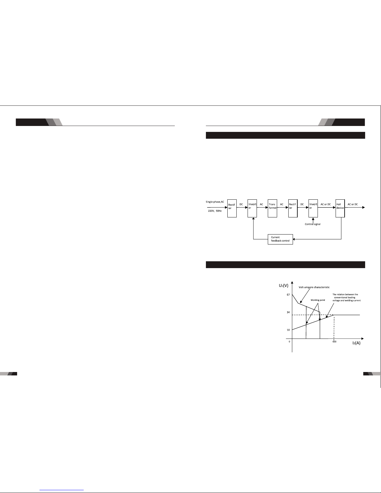
1.3 Volt - Ampere Cha racte ristic
Whe n I ≤600A , U =10 +0.04 I (V) ;
2 2 2
Whe n I >60 0A,U =34 (V).
2 2
1.2 Wor king Pr inciple
The w orki ng prin ciple o f TIG V 1841 V2 41 V341 AC /DC weldin g mach ines is sho wn as
the f ollow ing fig ure. Si ngle- phase 2 30V wor k frequ ency AC is r ectif ied int o DC (abo ut
312 V), the n is conv erted t o med ium fr eque ncy AC (ab out 20- 40KHz ) by inve rter de vice
(IG BT modu le), a fter re ducin g volta ge by med ium tra nsfor mer (th e main tr ansfo rmer) a nd
rec tifyi ng by med ium fre quenc y recti fier (f ast rec ove ry dio des) , then is o utput ted DC or AC
con tinuo usly an d stepl essly t o meet wi th the re quire ments o f weldi ng craf t.
wel ding ma chine h as an exc ellent
vol t-amp ere cha racte risti c, whos e
gra ph is sho wn as the f ollow ing
fig ure. Th e rela tion be tween t he
con venti onal ra ted loa ding vo ltage
U an d the con venti onal we lding
2
cur rent I i s as foll ows:
2
cu rrent o utp ut stab ly. M ean whi le, the w eld ing cur ren t par ame ter can b e adj usted
by se lect ing IG BT mod ule. Th e circ uit ad opts c urre nt fee dbac k cont rol te chno logy t o insu re
TI G V1 841/ V2 41/ V 341 AC/ DC
AC/DC SERIES EQUIPMENT
AC/DC SERIES EQUIPMENT
Sum mary Sum mary
111 0
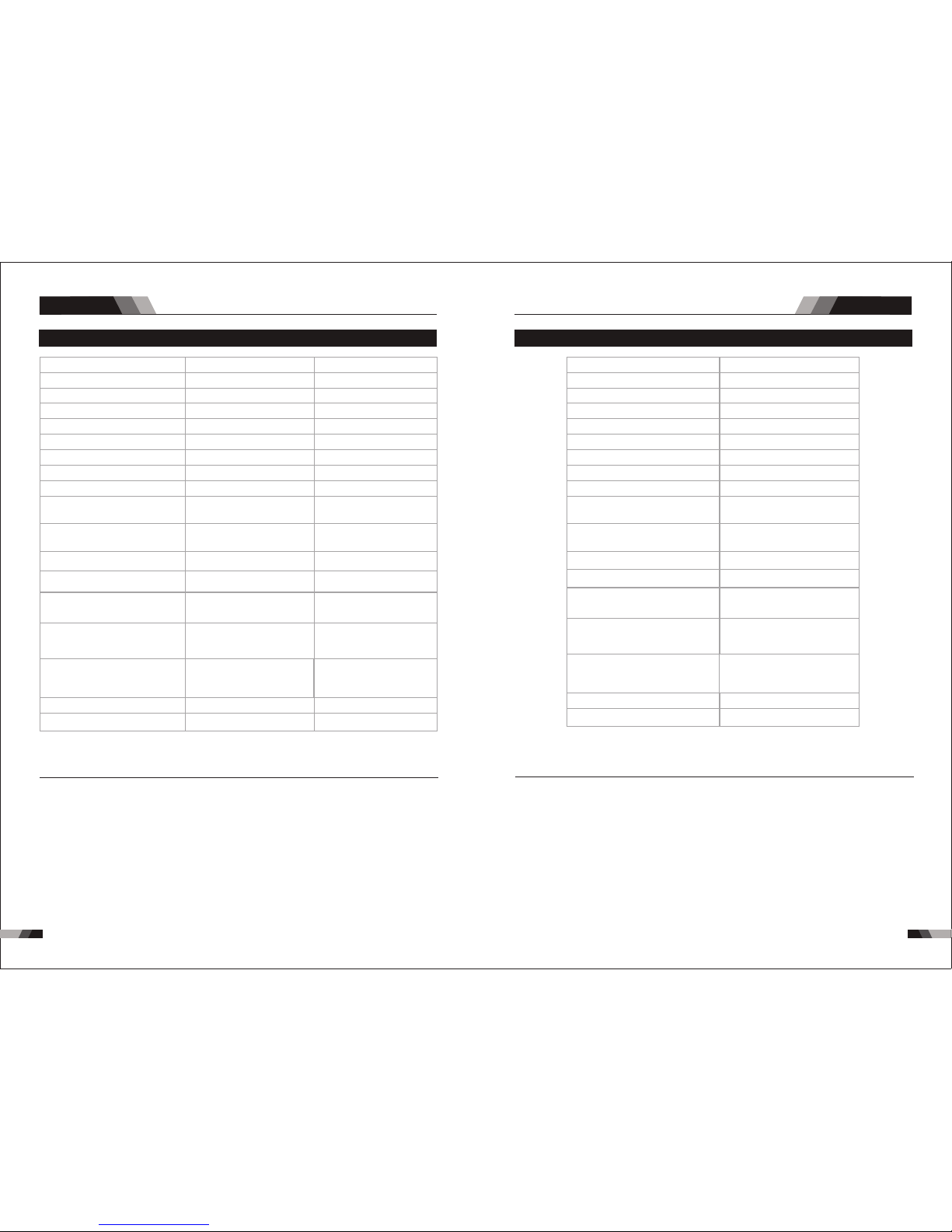
1.5 Specificat ions V3 411.4 Specificat ions V1 841/V241
NO TE
Not e 1: The Ef fect ive In put Cur rent sh ould be u sed for t he dete rmina tion of c able si ze &
Not e 1: The Ef fect ive In put Cur rent sh ould be u sed for t he dete rmina tion of c able si ze &
sup ply r equi reme nts .
sup ply r equi reme nts .
Not e 2: Gene rator R equir ement s at the Ma ximum O utput D uty Cyc le.
Not e 2: Gene rator R equir ement s at the Ma ximum O utput D uty C ycle .
Not e 3: Moto r start f use s or the rmal c ircui t break ers are r ecomm ended f or this a ppl icat ion.
Not e 3: Moto r start f use s or the rmal c ircui t break ers are r eco mmen ded fo r this ap plica tion.
Che ck lo cal re quir ement s for you r sit uati on in th is rega rd.
Che ck lo cal re quir ement s for you r sit uati on in th is re gard .
Due t o varia tions t hat can o ccur in m anufa cture d produ cts, cl aimed p erfor mance , volta ges,
Due t o varia tions t hat can o ccur in m anufa cture d produ cts, cl aimed p erfor mance , volta ges,
rat ings, a ll capa citie s, meas ureme nts, di mensi ons and w eight s quote d are app roxim ate
rat ings, a ll capa citie s, meas ureme nts, di mensi ons and w eight s quote d are app roxim ate
onl y. Achieva ble ca pacitie s and ra tings in us e and op eration w ill de pend upon c orre ct
onl y. Achieva ble ca pacitie s and ra tings in us e and op eration w ill de pend upon c orre ct
ins talla tion, u se, app licat ions, m ainte nance a nd serv ice.
ins talla tion, u se, app licat ions, m ainte nance a nd serv ice.
IP2 3
IP2 3
Des cript ionDes cript ion
Wei ghtWei ght
Pow er Sour ce Dime nsion sPow er Sour ce Dime nsion s
Coo lingCoo ling
Wel der Typ eWel der Typ e
Eur opean S tanda rdsEur opean S tanda rds
Num ber of Ph asesNum ber of Ph ases
Nom inal Su pply Vol tageNom inal Su pply Vol tage
Nom inal Su pply Fr equen cyNom inal Su pply Fr equen cy
Wel ding C urrent Ran ge
(DC S TICK Mo de)
Wel ding C urren t Range
(DC S TICK Mo de)
Wel ding C urrent Ran ge
(DC T IG Mod e)
Wel ding C urren t Range
(DC T IG Mod e)
Sin gle Pha se Gene rator
Req uirem ent
Sin gle Pha se Gene rator
Req uirem ent
STI CK (MMA )
Wel ding O utput , 40ºC, 1 0 min.
STI CK (MMA )
Wel ding O utput , 40ºC, 1 0 min.
TIG ( GTAW)
Wel ding O utput , 40ºC, 1 0 min.
TIG ( GTAW)
Wel ding O utput , 40ºC, 1 0 min.
Ope n circu it volt age
Ope n circu it volt age
Pro tecti on Clas s
Pro tecti on Clas s
Max imum In put Cur rent
Max imum In put Cur rent
Effective Input Current
Effective Input Current
VEC TOR DIG ITAL V24 1 AC/ DC
21. 9 kg
H52 5mmxW 260mm xD445 mm
Fan C ooled
Inv erter P ower So urce
EN 60 974-1 / I EC 6097 4-1
1
230 V +/- 15%
50/ 60Hz
10 - 20 0A
10 - 20 0A
29. 5A
41. 7A
14. 4kVA
200 A @ 50% , 28V
141 A @ 100 %, 25. 6V
200 A @ 50% , 18V
141 A @ 100 %, 15. 6V
66V D C
IP2 3
VEC TOR DIG ITAL V34 1 AC/ DCVEC TOR DIG ITAL V18 41 AC/DC
26. 4 kg
10. 9 kg
Fan C ooledFan C ooled
Inv erter P ower So urceInv erter P ower So urce
EN 60 974-1 / I EC 6097 4-1EN 60 974-1 / I EC 6097 4-1
31
400 V +/- 15%230 V +/- 15%
50/ 60Hz50/ 60Hz
30 - 30 0A10 - 17 0A
10 - 30 0A10 - 18 0A
12. 4A
20A
17. 5A
33. 9A
18. 2KVA
11.7 KVA
300 A @ 50% , 32.0 V
212 A @ 100 %, 28. 5V
170 A @ 35% , 26. 8V
100 A @ 100 %, 24V
300 A @ 50% , 22.0 V
212 A @ 100 %, 18. 5V
180 A @ 35% , 17. 2V
107 A @ 100 %, 14. 3V
66V D C
66V D C
H52 5mmxW 260mm xD445 mmH39 5mmxW 180mm xD375 mm
AC/DC SERIES EQUIPMENT
AC/DC SERIES EQUIPMENT
Sum mary
2.1 Layout For The P anel V1 841
1312
Ope ratio n
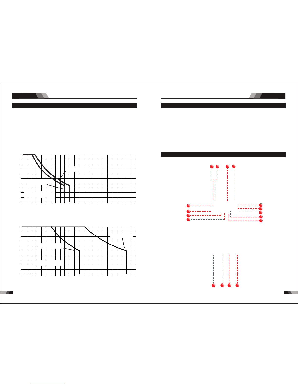
1.6 Duty Cy cle
The r ated d uty cyc le of a Wel ding P ower So urce, i s a state ment of t he ti me it ma y be
ope rated a t its rat ed weld ing cur rent ou tput wi thout e xceed ing the t emper ature l imits o f
th e in sulat ion of t he c omp one nt p ar ts. To ex pla in t he 1 0 mi nut e du ty c ycl e perio d th e
fo llo win g exa mpl e is u sed . Sup pos e a Wel din g Pow er S our ce i s des ign ed to ope rat e at
a 50 % dut y cyc le, 300 a mpe res a t 32 vo lts . Thi s mea ns th at it has b een des ign ed an d
buil t to p rov ide the rat ed am per age ( 300 A) fo r 5 mi nut es, i.e . arc wel din g tim e, out of
ev ery 10 mi nut e per iod ( 50% o f 10 m inu tes i s 5 mi nut es) . Dur ing t he o the r 5 mi nut es of
th e 10 m inu te peri od th e Wel din g Pow er So urc e mus t id le a nd b e al low ed to cool. T he
the rmal cu t out wil l opera te if the d uty cyc le is exc eeded .
◆3M Po wer cor d
◆200 Am p elect rode ho lder wi th 3M cab le
◆200 Am p earth c lamp wi th 3M cab le
◆4M TI G Torch WP2 6
◆3M Ga s Hose
◆Ope ratin g Manua l
1.7 Packa ged Ite ms
V1841/V 241
◆3M Po wer cor d
◆300 Am p elect rode ho lder wi th 3M cab le
◆300 Am p earth c lamp wi th 3M cab le
◆4M TI G Torch WP1 8
◆3M Ga s Hose
◆Ope ratin g Manua l
V341
Duty Cyc le( PERCENTA GE)
Weldi ng Curr ent(A MPS)
10 0 12 0 14 0 16 0 18 0 2 00 2 20
0
10
20
30
40
50
60
70
80
90
10 0
24 0 26 0 28 0 30 0 32 00
Saf e Opera ting Re gion
(TI G&STI CK)
V18 41 TIG
V18 41 STIC K
Duty Cyc le( PERCENTA GE)
Weldi ng Curr ent(A MPS)
10 0 12 0 14 0 16 0 18 0 2 00 2 20
0
10
20
30
40
50
60
70
80
90
10 0
24 0 26 0 28 0 30 0 32 00
V24 1 STICK /TIG
V34 1 STICK /TIG
3
2
1
4
8
7
5
14
15
16
17
6
12
13
9
10
11
3
2
1
4
8
7
5
14
15
16
17
6
12
13
9
10
11
Saf e Opera ting Re gion
(TI G&STI CK)
1. Digit al Ammete r / Par ameter me ter
The digita l Ammeter i s used t o displ ay the a ctua l outpu t curr ent of the powe r sour ce. It is
als o used to d ispla y Param eters i n Progr ammin g Mode.
De pend ing o n the Progr amm ing Pa ram eter sele cte d, the s tatu s indi cto r adjacen t to th e
Amme ter wil l illum inate t o show th e units o f the pro gramm ing par amete r.
Whe n weldi ng, the Am meter w ill dis play ac tual we lding c urren t.
2. Power O N Ind ica tor
4. Ar cforce/Hot S tar t/Hotst art c urr ent
The PO WER ON i ndicator il lumi nates when th e ON/OF F swit ch is in th e ON pos ition a nd
Cha nge the select ed weld f uncti ons mode from we ldin g curre nt to hot start t o start t ime to
arc fo rce from the digital d ispla y.
the c orrec t mains v olt age is p rese nt.
3. Therm al Ov erl oad Indic ato r Lig ht
Thi s weld ing pow er sour ce is pro tecte d by a self r esett ing the rmost at. The i ndic ator wi ll
illumi nat e if the d uty c ycle o f the p ower s ourc e has be en ex ceed ed. S houl d the th erma l
ov erl oad indic ator i llu min ate t he output o f the po wer s our ce wi ll be d isa ble d. Once the
po wer s our ce cools down th is lig ht wi ll go O FF an d the o ver t emp era tur e con diti on wil l
au tomatic all y res et. N ote th at the m ain s pow er sw itch s houl d rem ain i n the o n posi tion
su ch that the f an con tin ues t o oper ate th us al low ing th e unit t o coo l suff icie ntl y. Do not
swi tch the u nit off s houl d a therm al over load co nditi on be pre sent.
AC/DC SERIES EQUIPMENT
AC/DC SERIES EQUIPMENT
Ope ratio n
Ope ratio n
1514
5. JOB and S AVE
You ca n pre ss JO B to se lect t he me mor y rec ord s tha t you h ave s ave d bef ore f rom 1 -9.
For t he ne w sett ing of p resen t curre nt Amp s ,jus t pres s SAVE.
6. Mode Bu tto n
Pre ss th e MODE b utto n to to ggle AC a nd DC ou tput in L IFT TIG , HF TIG .
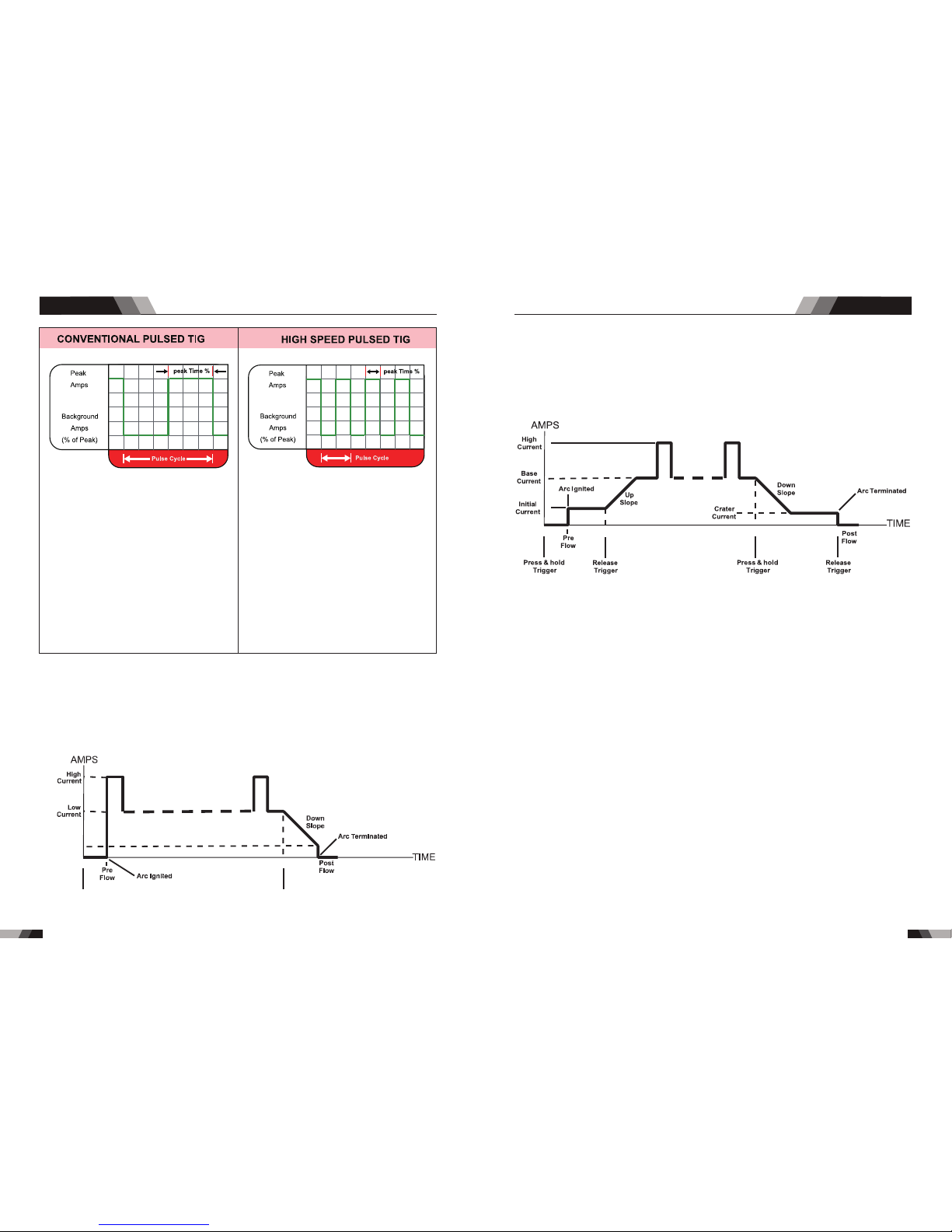
7. Trigge r Mod e Con trol Butt on (H F TIG a nd LIFT TIG M ode o nly)
The t rig ger mo de con trol is u sed to sw itch th e funct ion alit y of the t orc h trig ger be tween
2T an d 4T.
Min imum
Cur rent
Pre ss & hold
Trig ger
Rel ease
Trig ger
No te: th at w hen op erati ng i n GT AW (HF a nd L IFT T IG m od es ), t he p ow er s ou rc e wi ll
rem ain act ivate d until t he sele cted do wn slop e time ha s elaps ed
8. Proce ss Se lec tion Butt on
Th e pro ces s sel ect ion c ont rol i s use d to se lec t the d esi red w eld ing m ode . Two mo des
are a vaila ble, GTAW ( TIG ), and M MA (Sti ck) m odes .
9. Pulse B utt on
Pre ss the PU LSE b utto n to tog gle P ulse O n and OF F.
10. Prog ram min g Paramet er In dic ators
The se ind icato r light s will il lumin ate whe n progr ammin g.
Set ting ra nges
Arcfor ce: 1-1 00AMP Hot S tart:0.1-0 .5S H otstart curr ent :1-100 AMP
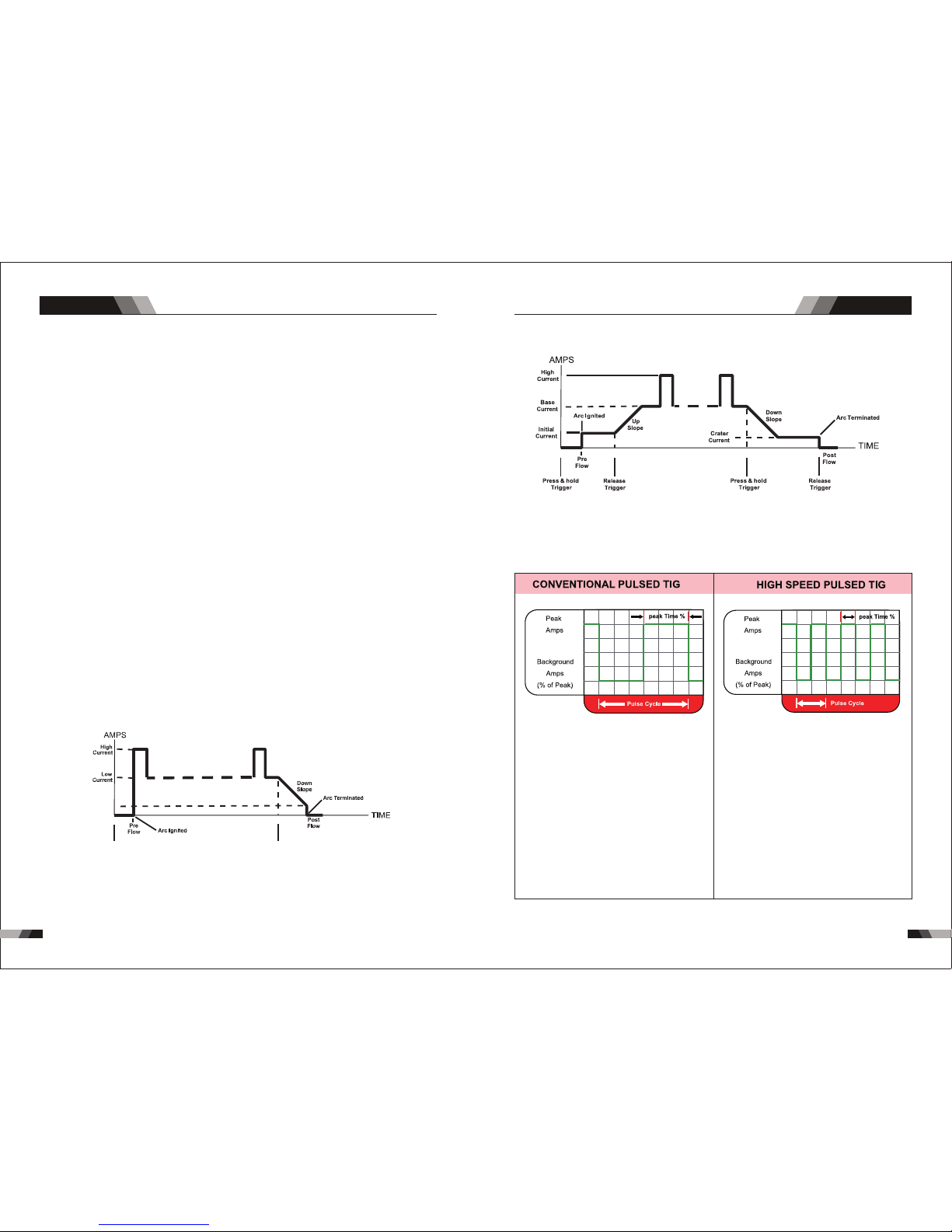
Typi cally f rom 1 to 10 P PS. Pro vides a h eatin g
and c oolin g effec t on the w eld pud dle an d can
red uce dis torti on by low ering t he aver age
amp erage . Th is heat ing and c oolin g effec t also
pro duces a d istin ct ripp le patt ern in th e weld
bea d. The re lati onshi p betwe en pul se freq uency
and t ravel s peed de termi nes the d istan ce
bet ween th e rippl es. Slo w pulsi ng can al so be
coo rdina ted wit h fille r metal a dditi on and
inc rease o veral l contr ol of the w eld pud dle
In ex cess of 4 0 PPS, Pu lsed TI G beco mes mor e
aud ible th an visi ble-c ausin g incre ased pu ddle
agi tatio n for a bet ter as- welde d micro struc ture.
Pul sing th e weld cu rrent a t high sp eeds- betwe en
a hig h Peak an d a low Bac kgrou nd ampe ragecan a lso con stric t and foc us the ar c.Thi s resul ts
in ma ximum a rc stab ility, i ncre ased pe netra tion
and i ncrea sed tra vel spe eds(C ommon R ange:
100 -500 PP S).
The Ar c-Sha rpeni ng effe cts of h igh spe ed
pul sing ar e expan ded to ne w dimen sions . The
abi lity to p ulse at 5 ,000P PS furt her enh ances
arc s tabil ity and c oncen trati on pote ntial -whic h
is ex tre mel y benef icial t o autom ation w here
max imum tr avel ts peeds a re requ ired.
ou tput t o be ac tive .
Press an d hol d the to rch t rigg er to a ctiv ate th e powe r sou rce (w eld) . Rele ase t he tor ch
trigge r swi tch to c eas e weld ing .
2T N orm al M ode In th is mo de, t he to rch t rig ger mus t rem ain p res sed for the wel din g
op era tor f atigu e. I n thi s mod e th e ope rat or ca n pre ss an d re lea se t he to rch t rig ger a nd
to rch tri gger.
4T La tc h mod e th is m ode of we ld in g is ma inly u sed fo r lo ng w el din g ru ns t o re duce
th e out put wil l rem ain act ive . To d eac tiv ate t he p owe r sourc e, th e tr igg er sw itc h must
ag ain be p re ssed a nd r el eased , th us e li minat ing th e ne ed f or t he o per ato r to h old the
AC/DC SERIES EQUIPMENT
AC/DC SERIES EQUIPMENT
Ope ratio n
Ope ratio n
Lo ose wel ding te rmi nal c onn ect ion s can cau se o ver heati ng a nd re sul t in t he ma le pl ug
be ing fus ed i n the ter min al.
2.2 Control Pane l
.Gas Pre-Fl ow 1
Abs olut e sett ing r ange 0 .1s to 5 s (0. 1S inc reme nts )
Thi s param eter op erate s in TIG mo des on ly and is u sed to pr ovide g as to the w eld zon e
use d to dram atica lly red uce wel d poros ity at th e start o f a weld.
2.Init ial C urr ent
The m ain cur ren t Sett ing ra nge 1 0AMP t o 100A MP
Thi s parameter ope rates i n (4T) TIG m odes onl y and is used to set the start cu rrent f or TIG.
Th e Sta rt Cu rre nt rema ins o n un til t he torc h tri gge r swi tch i s rel eas ed af ter i t has bee n
dep resse d.
No te: T he ma xim um in iti al cu rre nt avai lab le wi ll b e lim ite d to t he se t val ue o f the bas e
cur ren t.
3.Up Slo pe
Set ting ra nges :0 .1S -10S ( 0.1S i ncr emen ts)
Thi s para mete r oper ates in (2T an d 4T) TIG modes only and is use d to set t he tim e for th e
we ld cu rre nt to ram p up, aft er th e tor ch tr igger sw itc h has b een pre sse d then re lea sed ,
fro m Initi al Curr ent to Hi gh or bas e curre nt.
4.Peak C urr ent
Set ting ra nges
V18 41: 10- 18 0A( DC TIG a nd AC HF T IG) ,10 -170A( Sti ck mod e)
Th is p ara met er sets t he TI G WE LD cu rre nt. T his p ara met er a lso set s th e ST ICK w eld
cur rent.
5.Base C urr ent
Set ting ra nges
V18 41:10 AMP to 18 0AMP ( DC TIG m ode), 10A MP to 18 0AMP ( AC HF TI G mode )
Sec ondar y curre nt (TIG )/pul se paus e curre nt.
6.Puls e Wid th
Set ting ra nges 10 %-90%
Th is pa ram ete r set s the p erc ent age o n tim e of th e PUL SE FR EQU ENC Y for H igh weld
cur rent wh en the PU LSE is ON .
7.Puls e Fre que ncy
Set ting ra nge s 1HZ -2 00HZ
Thi s param eter se ts the PU LSE F REQU ENCY w hen th e PULSE i s ON.
8.Down S lop e
Set ting ra nges 0. 1-1 0s
Thi s parameter o pera tes in TIG modes o nly and i s used to s et the time for t he weld c urre nt
to r amp d own, afte r the to rch t rig ger switc h has b een p res sed t o end c urre nt. Th is co ntro l
is us ed to eli minat e the cra ter tha t can for m at the co mpl etio n of a wel d.
9.End Cu rre nt
Set ting ra nges 10 A-180 A
This pa ramete r operate s in (4T) TIG mod es only and is us ed to set the fin ish curre nt for TIG.
The e nd current re main s ON unti l the to rch tri gger s witch is rele ased after it h as been
dep resse d.
No te: T he ma xim um crat er cu rre nt av ail abl e wil l be l imi ted t o the set v alu e of th e base
cur ren t.
10. Post F low
Set ting ra nges 1. 0-1 0S
Th is p arame te r ope rat es i n TI G modes o nly a nd is use d to ad jus t th e po st g as flow
ti me o nc e th e ar c ha s ex ti ng ui she d. T hi s co nt ro l is us ed t o dr am atic al ly r ed uc e
ox ida tio n of t he tu ngs ten e lec tro de.
171 6
17. Posi tiv e Welding Te rminal
Po sit ive W eld ing Ter min al. Wel din g cu rre nt f low s fr om th e Pow er S our ce v ia he avy
du ty ba yon et ty pe te rmi nal s. It i s ess ent ial , how eve r, th at th e mal e plu g is i nsert ed
and t urn ed sec urel y to achi eve a sou nd elec trica l conne ction .
and t urn ed sec urel y to achi eve a sou nd elec trica l conne ction .
15. Shie ldi ng Ga s Outlet
Th e Shi eld ing G as Ou tle t loc ate d on th e fro nt pa nel i s a fas t conn ecti on of a s uita ble
TIG Tor ch.
14. Nega tiv e Welding Te rminal
Ne gat ive W eld ing Te rmi nal . Wel din g cur ren t flo ws fr om th e Pow er So urce via h eav y
du ty ba yon et t ype t erm ina ls. I t is es sen tia l, ho wev er, t hat the mal e pl ug is ins ert ed
16. 5 Pin Co ntr ol So cket
The 5 pin rece ptac le is us ed to co nnec t a trig ger switch or r emot e cont rol to t he wel ding
Pow er Sour ce circ uit ry:
To make connectio ns, align ke yway, insert plug, and rota te thread ed collar fu lly clock wise.
12. Nega tiv e Con trol
13. Sele cti ng Fu nction Bu tto n
The N egat ive but ton is us ed to min us sele cted in P rogra mming s equen ce.
Thi s butt on can se lect di ffere nt pro gramm ing par amete r from No . 10
11. Posit ive C ont rol
The P osit ive but ton is us ed to plu s selec ted in Pr ogr ammi ng seq uence .
CAUTION
pr ior to s trik ing th e arc, o nce t he tor ch tr igg er swi tch h as be en pre ssed . This c ont rol is
AC/DC SERIES EQUIPMENT
AC/DC SERIES EQUIPMENT
Ope ratio n
Ope ratio n
1918
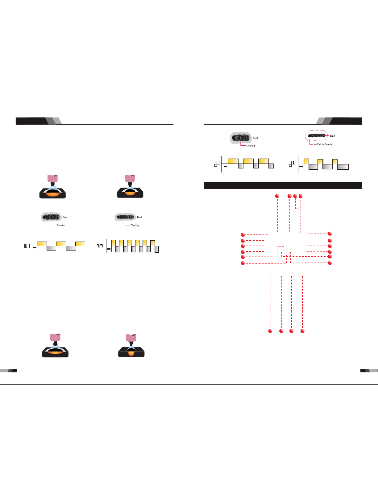
12.Wave Balance
Set ting ar range s 10%-5 0%
T hi s pa ra me te r o pe ra te s in AC T IG mo de an d i s u se d to se t t he pe ne tr at io n t o
cl ean ing act ion ra tio fo r th e AC w el d cu rr ent. G enera lly WAVE BALAN CE i s se t to
5 0% fo r AC ST IC K we ld in g. T he WAV E B AL AN CE co nt ro l c ha ng es th e ra ti o o f
pe net rat ion t o cle ani ng ac tio n of th e AC TI G wel din g arc . Max imu m wel d penet rat ion
i s ac hie ved when t he WAV E BA LANCE con tro l is s et t o 10 %. Ma xim um c lea nin g of
h ea vi ly ox id is ed a lu mi ni um o r m ag ne si um a ll oy s is ac hi ev ed wh en t he WAV E
B AL AN CE co nt ro l is se t t o 5 0%
Wid er bead , good pe netra tion
ide al for bu ildup w ork
Nar rower b ead for f illet w elds an d
aut omate d appli catio ns
Wid er bead a nd clea ning ac ting Nar rower b ead and c leani ng acti ng
AC Ba lance C ontro l
Co ntr ols a rc cl ean ing a ction. Ad jus ting the % E N of th e AC wav e cont rol s the w idth o f the
etc hing zo ne surr oundi ng the we ld.
No te : Se t the A C Ba lan ce co ntr ol f or a deq uat e ar c cl ean ing a cti on a t th e si des and in
fr ont of t he w el d pu dd le . AC B al an ce s hou ld b e fi ne t uned a cc or ding t o ho w he av y or
thi ck the ox ides ar e.
Wid er bead , good pe netra tion
ide al for bu ildup w ork
Nar rower B ead, Go od Pene trati on
Ide al For Bu ildup W ork
Wid er bead a nd clea ning ac tion Nar rower b ead, wi th no vis ible cl eanin g
2.3 Layout For The P anel V2 41/V341
10
11
12
13
14
15
9
6 78
5
4
3
2
1
16
17
18
19
20
1. RE SET B utton
Whe n softw are h as pro blem p lease t rigge r RESET b utto n.
2. Pu lse B utton
Pre ss the PU LSE b utto n to tog gle P ulse O n and OF F.
AC Fr equen cy cont rol
Con trols t he widt h of the ar c cone. I ncrea sing th e AC fr eque ncy pr ovides a mor e focu sed
arc w ith inc rease d direc tiona l contr ol.
No te : De creasi ng t he AC Fr eq ue nc y so ft en s th e ar c and b ro ade ns t he w el d pu dd le
f or a wi de r we ld b ead .
11. AC F requency
Set ting ra nges 50 HZ-20 0HZ
Th is pa rame ter op era tes i n AC TIG m ode o nly a nd is u sed t o set t he fr equency f or the
AC we ld curr ent.
3. Trigge r Mod e Con trol Butt on (H F TIG a nd LIFT TIG M ode o nly)
The t rig ger mo de con trol is u sed to sw itch th e funct ion alit y of the t orch tr igg er bet ween
2T an d 4T.
ou tput t o be ac tive .
Press an d hol d the to rch t rigg er to a ctiv ate th e powe r sou rce (w eld) . Rele ase t he tor ch
trigge r swi tch to c eas e weld ing .
2T N orm al M ode In th is mo de, t he to rch t rig ger mus t rem ain p res sed for the wel din g
AC/DC SERIES EQUIPMENT
AC/DC SERIES EQUIPMENT
Ope ratio n
Ope ratio n
No te : th at w he n op er at in g in G TAW ( HF a nd L IF T TI G mo des ), t he p ow er s ou rc e wi ll
rem ain act ivate d until t he sele cted do wn slop e time ha s elaps ed
Min imum
Cur rent
Pre ss & hold
Tri gger
Rel ease
Tri gger
4. Proce ss Se lec tion Butt on
Th e pro ces s sel ect ion c ont rol i s use d to se lec t the d esi red w eld ing m ode . Two mo des
are a vaila ble, GTAW ( TIG ), and M MA (Sti ck) m odes .
cur rent of t he po wer so urce .
At ti mes of n on-w eldi ng, t he amp erag e mete r wil l display a p re- set (p revi ew) am per age
val ue. Thi s valu e can be ad juste d by vary ing the m ultif uncti on cont rol whe n the
Pro gramm ing Par amete r Indic ator li ght sho ws BASE C URR ENT.
5. Digit al Ammete r
The digital ampe rage m eter i s used to d ispl ay bot h the pr e-set curre nt and a ctua l outp ut
6. Digit al Vol tmeter / Pa ram eter Meter
The di gita l volt me ter is us ed to dis play th e actual outp ut volt age of th e power sourc e. It is
als o used to d ispla y Param eters i n Progr ammin g Mode.
De pend ing o n the Progr amm ing Pa ram eter sele cte d, the s tatu s indi cto r adjacen t to th e
vol t meter w ill ill umina te to sho w the uni ts of the p rogra mming p arame ter.
Whe n weldi ng, the v olt met er will d ispla y actua l weldi ng volt age.
7. Power O N Ind ica tor
The PO WER ON i ndicator il lumi nates when th e ON/OF F swit ch is in th e ON position a nd
the c orrec t mains v oltag e is pres ent.
2120
Typi cally f rom 1 to 10 P PS. Pro vides a h eatin g
and c oolin g effec t on the w eld pud dle an d can
red uce dis torti on by low ering t he aver age
amp erage . Th is heat ing and c oolin g effec t also
pro duces a d istin ct ripp le patt ern in th e weld
bea d. The re lati onshi p betwe en pul se freq uency
and t ravel s peed de termi nes the d istan ce
bet ween th e rippl es. Slo w pulsi ng can al so be
coo rdina ted wit h fille r metal a dditi on and
inc rease o veral l contr ol of the w eld pud dle
In ex cess of 4 0 PPS, Pu lsed TI G beco mes mor e
aud ible th an visi ble-c ausin g incre ased pu ddle
agi tatio n for a bet ter as- welde d micro struc ture.
Pul sing th e weld cu rrent a t high sp eeds- betwe en
a hig h Peak an d a low Bac kgrou nd ampe ragecan a lso con stric t and foc us the ar c.Thi s resul ts
in ma ximum a rc stab ility, i ncre ased pe netra tion
and i ncrea sed tra vel spe eds(C ommon R ange:
100 -500 PP S).
The Ar c-Sha rpeni ng effe cts of h igh spe ed
pul sing ar e expan ded to ne w dimen sions . The
abi lity to p ulse at 5 ,000P PS furt her enh ances
arc s tabil ity and c oncen trati on pote ntial -whic h
is ex tre mel y benef icial t o autom ation w here
max imum tr avel ts peeds a re requ ired.
8. Therm al Ov erl oad Indic ato r Lig ht
Thi s weld ing pow er sour ce is pro tecte d by a self r esett ing the rmost at. The i ndic ator wi ll
illumi nat e if the d uty c ycle o f the p ower s ourc e has be en ex ceed ed. S houl d the th erma l
ov erl oad indic ator i llu min ate t he output o f the po wer s our ce wi ll be d isa ble d. Once the
po wer s our ce cools down th is lig ht wi ll go O FF an d the o ver t emp era tur e con diti on wil l
au tomatic all y res et. N ote th at the m ain s pow er sw itch s houl d rem ain i n the o n posi tion
su ch that the f an con tin ues t o oper ate th us al low ing th e unit t o coo l suff icie ntl y. Do not
swi tch the u nit off s houl d a therm al over load co nditi on be pre sent.
op era tor f atigu e. I n thi s mod e th e ope rat or ca n pre ss an d re lea se t he to rch t rig ger a nd
to rch tri gger.
4T La tc h mod e th is m ode of we ld in g is ma inly u sed fo r lo ng w el din g ru ns t o re duce
th e out put wil l rem ain act ive . To d eac tiv ate t he p owe r sourc e, th e tr igg er sw itc h must
ag ain be p re ssed a nd r el eased , th us e li minat ing th e ne ed f or t he o per ato r to h old the
AC/DC SERIES EQUIPMENT
AC/DC SERIES EQUIPMENT
Ope ratio n
Ope ratio n
Lo ose wel ding te rmi nal c onn ect ion s can cau se o ver heati ng a nd re sul t in t he ma le pl ug
be ing fus ed i n the ter min al.
1.Gas Pr e-F low
V24 1: Abso lute s etti ng ra nge 0. 1s to 20 s (0. 1S inc reme nts )
V34 1: Abso lute s etti ng ra nge 0. 1s to 20 s (0. 1S inc reme nts )
Thi s param eter op erate s in TIG mo des on ly and is u sed to pr ovide g as to the w eld zon e
use d to dram atica lly red uce wel d poros ity at th e start o f a weld.
2.4 Control Pane l
17. Posi tiv e Welding Te rminal
Po sit ive W eld ing Ter min al. Wel din g cu rre nt f low s fr om th e Pow er S our ce v ia he avy
du ty ba yon et ty pe te rmi nal s. It i s ess ent ial , how eve r, th at th e mal e plu g is i nsert ed
and t urn ed sec urel y to achi eve a sou nd elec trica l conne ction .
18. 5 Pin Co ntr ol So cket
The 5 pin rece ptac le is us ed to co nnec t a trig ger switch or r emot e cont rol to t he wel ding
Pow er Sour ce circ uit ry:
To make connectio ns, align ke yway, insert plug, and rota te thread ed collar fu lly clock wise.
20. Shie ldi ng Ga s Outlet
Th e Shi eld ing G as Ou tle t loc ate d on th e fro nt pa nel i s a fas t conn ecti on of a s uita ble
TIG Tor ch.
19. Nega tiv e Welding Te rminal
Ne gat ive W eld ing Te rmi nal . Wel din g cur ren t flo ws fr om th e Pow er So urce via h eav y
du ty ba yon et t ype t erm ina ls. I t is es sen tia l, ho wev er, t hat the mal e pl ug is ins ert ed
and t urn ed sec urel y to achi eve a sou nd elec trica l conne ction .
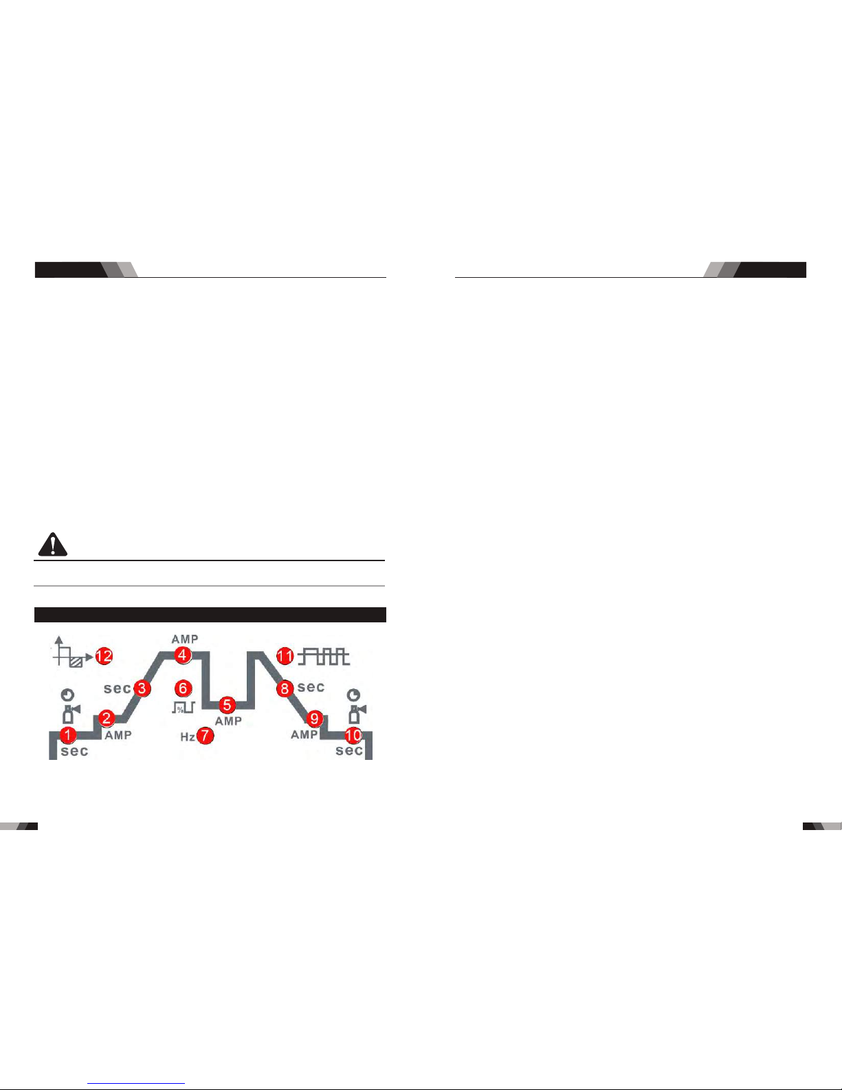
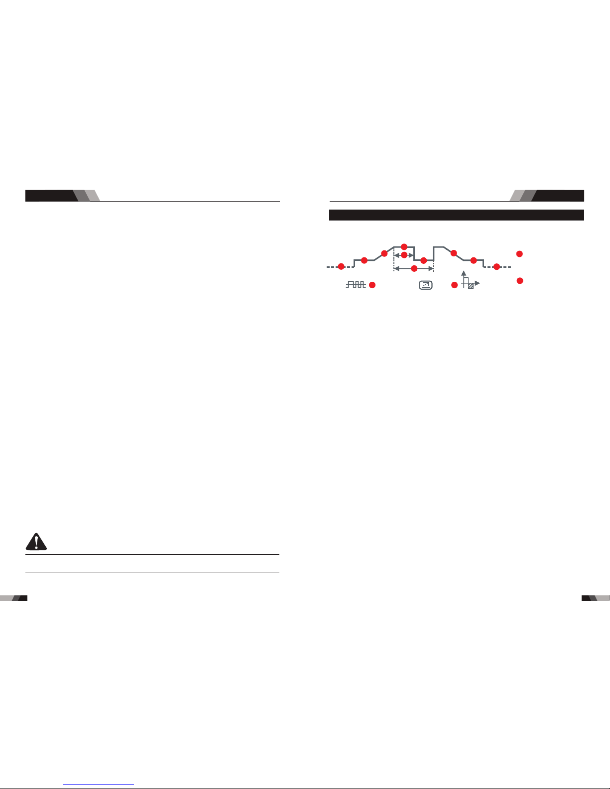
AC Fr equen z
Wav e Bala nce
Rem ote
ARC H otsta rt
ARC S tart Tim e
Arc force C orrec tion
AMP %
sec
AMP
%
HZ
sec
AMP %
sec
AMP %
sec
%
1
2
3
4
6
5
7
11
12
8
9
10
13
14
2.Init ial C urr ent
V241:T he ma in cur rent S ett ing ra nge 10 AMP to 2 00A MP
This parame ter oper ates in (4 T) TIG mod es only and is used to set the start curren t for TIG.
Th e Sta rt Curr ent r ema ins o n unt il th e tor ch trigg er sw itc h is rele ase d aft er it has b een
dep resse d.
No te: T he ma xim um initi al cu rre nt av ail able wil l be li mit ed to the s et va lue of the b ase
cur ren t.
3.Up Slo pe
Set ting ra nge s :0.1 S-10 S (0. 1S inc reme nts)
Thi s param eter op erate s in (2T and 4 T) TIG mod es only a nd is used t o set the ti me for th e
we ld cur rent t o ram p up, a fter t he tor ch tr igg er swi tch ha s bee n pre ssed t hen re lea sed,
fro m Initi al Curr ent to Hi gh or bas e curre nt.
4.Peak C urr ent
Set ting ra nge s
V24 1:10- 20 0A( DC TIG a nd AC HF T IG) ,10 -20 0A(S tic k mode )
V34 1:10- 30 0A( DC TIG a nd AC HF T IG) ,30 -30 0A(S tic k mode )
Th is pa ramete r set s the TIG W ELD c urrent . Thi s par ameter a lso s ets t he ST ICK wel d
cur rent.
5.Base C urr ent
Set ting ra nge s
V24 1:10A MP to 200 AMP (D C TIG mo de), 1 0AMP to 2 00AMP (AC HF TIG mode)
V34 1:10A MP to 300 AMP (D C TIG mo de), 1 0AMP to 3 00AMP (AC HF TIG mode)
Sec ondar y curre nt (TIG )/pul se paus e curre nt.
232 2
9. JOB and S AVE
You ca n pre ss JO B to se lect t he me mor y rec ord s tha t you h ave s ave d bef ore f rom 1 -9.
For t he ne w sett ing of p resen t base cu rrent Am ps ,jus t press S AVE.
10. Prog ram min g Paramet er In dic ators
The se ind icato r light s will il lumin ate whe n progr ammin g.
11. HF Butt on
Pres s and hold the HF butt on to purge the gas li ne in LIF T TIG an d HF TIG modes. To HF
the shie ldi ng gas l ine i n LIFT T IG and H F TI G mode s pre ss the H F but ton an d rele ase.
12. Mode B utt on
Pre ss th e MODE b utto n to to ggle AC a nd DC ou tput in L IFT TIG , HF TIG a nd STI CK.
13. Forw ard P rog ramming B utt on
Pre ssi ng thi s butt on will a dvanc e to the ne xt step i n the pro gramm ing seq uence .
14. Back P rog ram ming Butt on
Pre ssi ng thi s butt on will g o back to t he prev ious st ep in the p rogra mming s equen ce.
15. Posi tiv e Con trol
The P osit ive but ton is us ed to plu s selec ted in Pr ogr ammi ng seq uence ..
16. Nega tiv e Con trol
The N egat ive but ton is us ed to min us sele cted in P rogra mming s equen ce..
CAUTION
V341:T he ma in cur rent S ett ing ra nge 10 AMP to 3 00A MP
pr ior to s trik ing the arc , onc e the t orch t rigg er sw itch h as be en pr esse d. Th is con trol i s
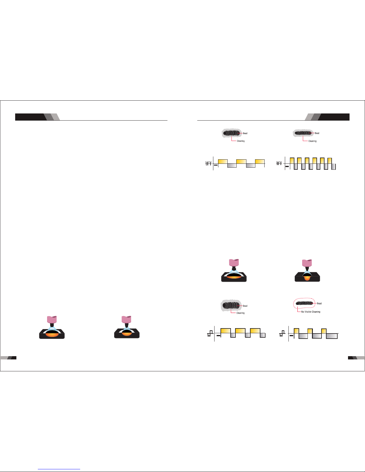
AC Ba lance C ontro l
Co ntr ols a rc cl ean ing a ction. Ad jus ting the % E N of th e AC wav e cont rol s the w idth o f the
etc hing zo ne surr oundi ng the we ld.
No te : Se t the A C Ba lan ce co ntr ol f or a deq uat e ar c cl ean ing a cti on a t th e si des and in
fr ont of t he w el d pu dd le . AC B al an ce s hou ld b e fi ne t uned a cc or ding t o ho w he av y or
thi ck the ox ides ar e.
Wid er bead , good pe netra tion
ide al for bu ildup w ork
Nar rower B ead, Go od Pene trati on
Ide al For Bu ildup W ork
Wid er bead a nd clea ning ac tion Nar rower b ead, wi th no vis ible cl eanin g
AC/DC SERIES EQUIPMENT
AC/DC SERIES EQUIPMENT
Ope ratio n Ope ratio n
AC Fr equen cy cont rol
Con trols t he widt h of the ar c cone. I ncrea sing th e AC fr eque ncy pr ovides a mor e focu sed
arc w ith inc rease d direc tiona l contr ol.
No te: D ecr eas ing t he AC F req uen cy so fte ns the a rc a nd b roade ns th e we ld p uddle
f or a w id er w eld be ad.
Wid er bead , good pe netra tion
ide al for bu ildup w ork
Nar rower b ead for f illet w elds an d
aut omate d appli catio ns
Wid er bead a nd clea ning ac ting Nar rower b ead and c leani ng acti ng
12.Wave Balance
Set ting ar range s 10%-5 0%
11. AC F requency
Set ting ra nges 50 HZ-20 0HZ
Th is pa rame ter op era tes i n AC TIG m ode o nly a nd is u sed t o set t he fr equency f or the
AC we ld curr ent.
2524
6.Puls e Wid th
Set ting ra nges 10 %-90%
Th is para met er s ets t he pe rce nta ge on t ime of th e PUL SE FR EQU ENC Y for Hig h wel d
cur rent wh en the PU LSE is ON .
7.Puls e Fre que ncy
Set ting ra nge s 1HZ -2 00HZ
Thi s param eter se ts the PU LSE F REQU ENCY w hen th e PULSE i s ON.
8.Down S lop e
Set ting ra nges 0. 1-10s
Thi s para mete r operates in T IG modes only a nd is us ed to set t he tim e for th e weld cu rren t
to ra mp down , after t he to rch tr igge r switc h has bee n press ed to end c urren t. This c ontr ol
is us ed to eli minat e the cra ter tha t can for m at the co mpl etio n of a wel d.
10. Post F low
V24 1: Sett ing ran ges 1-2 0S
V34 1: Sett ing ran ges 1-2 0S
Th is p ara met er op era tes i n TIG mod es o nly a nd is u sed to ad jus t the pos t ga s flo w
tim e once th e arc has e xting uishe d. This c ontr ol is use d to dram atica lly red uce
oxi datio n of the tu ngste n elect rode.
Thi s para mete r oper ates i n AC TIG mo de and i s used t o set the penetrat ion to clean ing
act ion ra tio fo r the AC we ld cur rent . Gene rall y WAVE BAL ANCE i s set to 5 0% for AC
STI CK wel ding . The WAVE B ALAN CE con trol c hang es the r atio o f pene trat ion to
the WAVE BALA NCE co ntro l is set t o 10%. M axim um cle anin g of hea vily o xidi sed
alu mini um or ma gnes ium al loys i s achi eved w hen th e WAVE BAL ANCE c ontr ol is se t to
50%
9.End cu rre nt
V24 1:Set ting ra nges 10 A-200 A
Thi s parame ter ope rates in ( 4T) TIG mod es only and is used to s et the fin ish current for TI G.
The e nd curr ent rem ains ON until t he torc h trigg er swit ch is release d after i t has bee n
dep resse d.
No te: T he m axi mum c rat er cu rre nt av ail abl e wil l be li mit ed to t he se t val ue of t he ba se
cur ren t.
V34 1:Set ting ra nges 10 A-300 A
cle anin g acti on of the AC TIG weld ing ar c. Max imum we ld pen etra tion is achie ved wh en

2.5 Setup For STIC K (MMA) Welding
WAR NIN G
CA UTI ON
CA UTI ON
Be fo re c onn ectin g th e wo rk c lam p to th e wo rk a nd
in ser tin g the ele ctr ode i n the ele ctr ode h old er ma ke
sur e the mai ns powe r sup ply is s witc hed o ff.
Re mov e any p ack agi ng m ate ria l pri or to use . Do n ot
bl ock the a ir ve nts a t the f ron t or rear o f th e Wel din g
Pow er Sour ce.
Lo os e we ldi ng t erm in al c on ne ct io ns c an c aus e
ov erh eat ing a nd resu lt i n th e ma le p lug bei ng fu sed
in th e bayon et te rmin al.
AC/DC SERIES EQUIPMENT
AC/DC SERIES EQUIPMENT
Ope ratio n
Ope ratio n
27
26
pow er supp ly
2.6 Set-up For LIF T TIG (GTAW) Wel ding
WAR NIN G
Bef ore any w eldin g is to b egin , be sur e to we ar all
app ropri ate and r eco mmen ded sa fety eq uip ment .
Ant istic k
Ant istic k
U
I
13. Hot St art
14. Ar cforce Co rre cti on
Hot S tart Fu nctio n relia bly ign ites th e elect rode
and m elts pe rfect ly to ens ure the b est qua lity
eve n at the st art of th e sea m. thi s solu tion ma kes
lac k of fusi on and co ld weld s a thing o f the pas t
and s ignif icant ly redu ces wel d reinf orcem ent.
Adj ust the h ot star t curre nt here a nd the ti me here .
Dur ing the w eldin g proce ss, arc force p reven ts
t he el ec tr od e s ti ck in g in th e w el d p oo l w it h
inc rease s in curr ent. th is make s it easi er to wel d
lar ge-dr op mel ting el ectro de typ es at low curren t
str ength s with a sh ort arc i n parti cular.
Ant i-sti ck prev ents th e elect rode fr om an neal ing.
If t he el ect rod e sti cks i n sp ite of th e arc ror ce d evi ce , the
mac hi ne au to ma ti ca ll y sw it ch es o ve r t o th e mi ni mum
cu rrent wi th in a bou t 1 se co nd t o pr event th e el ect ro de
e le ct ro de a nd el ec tr od e h ol de r t o pr ot ec t th e wel de r.
Fo r Alk alin e Elec tro de, con nec t the e lec trod e hold er to t he po sit ive w eld ing termi mal
El ectr ode, please c onne ct th e ele ctrode ho lder t o the n egat ive w elding termi mal a nd
ma nufa ctur er. We ldin g curr ent f low s from the Po wer So urc e via h eavy duty b ayon et ty pe
te rmin als. I t is es sen tial, how eve r, tha t the m ale p lug i s inserte d and t urn ed se curely to
ac hiev e a soun d ele ctr ical conn ecti on. S elect STI CK mo de wi th th e pro cess sele cti on
co ntro l.
a nd c on ne ct th e wo rk le ad to th e neg at iv e w el di ng te rm in al , wh il e f or th e A ci d
con nect the wor k lead to the po sitve wel ding t ermi nal. If in d oubt c onsu lt the e lect rode
f ro m o v er h e at i ng . I n or d er to e as i ly se p ar a t e t h e
2.8 Operation No tices
◆Height a bove sea le vel is belo w 100 0m.
◆Operat ion tempe rature ra nge:-10 ˚C~ +40˚ C.
◆Relati ve humidi ty is below 9 0%( 20˚C ).
◆Prefer ably site t he machin e som e angl es ab ove th e flo or lev el, the ma xim um
angle do es not exce ed 15˚.
◆The cont ent of dust ,acid,c orrosiv e gas i n the su rro undi ng ai r or sub sta nce
can not ex ceed norm al standa rd.
◆Take care th at there is s uffi cie nt ven til atio n dur ing we ldi ng.Ther e is at least
30cm fre e disstan ce betwee n the machi ne an d wall .
2.7 Operation En viron ment
◆Read saf ty instru ction and C hap ter 1 ca ref ully b efo re att emp ting t o use t his
equipm ent.
◆Connec t the groun d wire the ma chi ne dir ect ly
◆In case cl osing the p ower swit ch, no-lo ad vo ltag e may b e expo rte d.Do n ot to uch
the outp ut electr ode with an y part of you r bod y.
◆Before o peratio n,no conc ern ed peo ple s houl d be le ft,D o not w atch t he ar c in
unprot ected eye s.
◆Ensure g ood venti lation of t he ma chin e to im prov e dut y rati o.
◆Tur n off th e engine wh en the oper ati on fin ish ed to ec ono mize e ner gy sou rce .
◆When pow er switch s huts off pr otec tiv ely be cau se of fa ilu re.Don’ t restart i t until
until pr oblem is re solved.
Otherw ise,the r ange of pro blem will b e ext ende d.
AC/DC SERIES EQUIPMENT
AC/DC SERIES EQUIPMENT
Ope ratio n Ope ratio n
2928
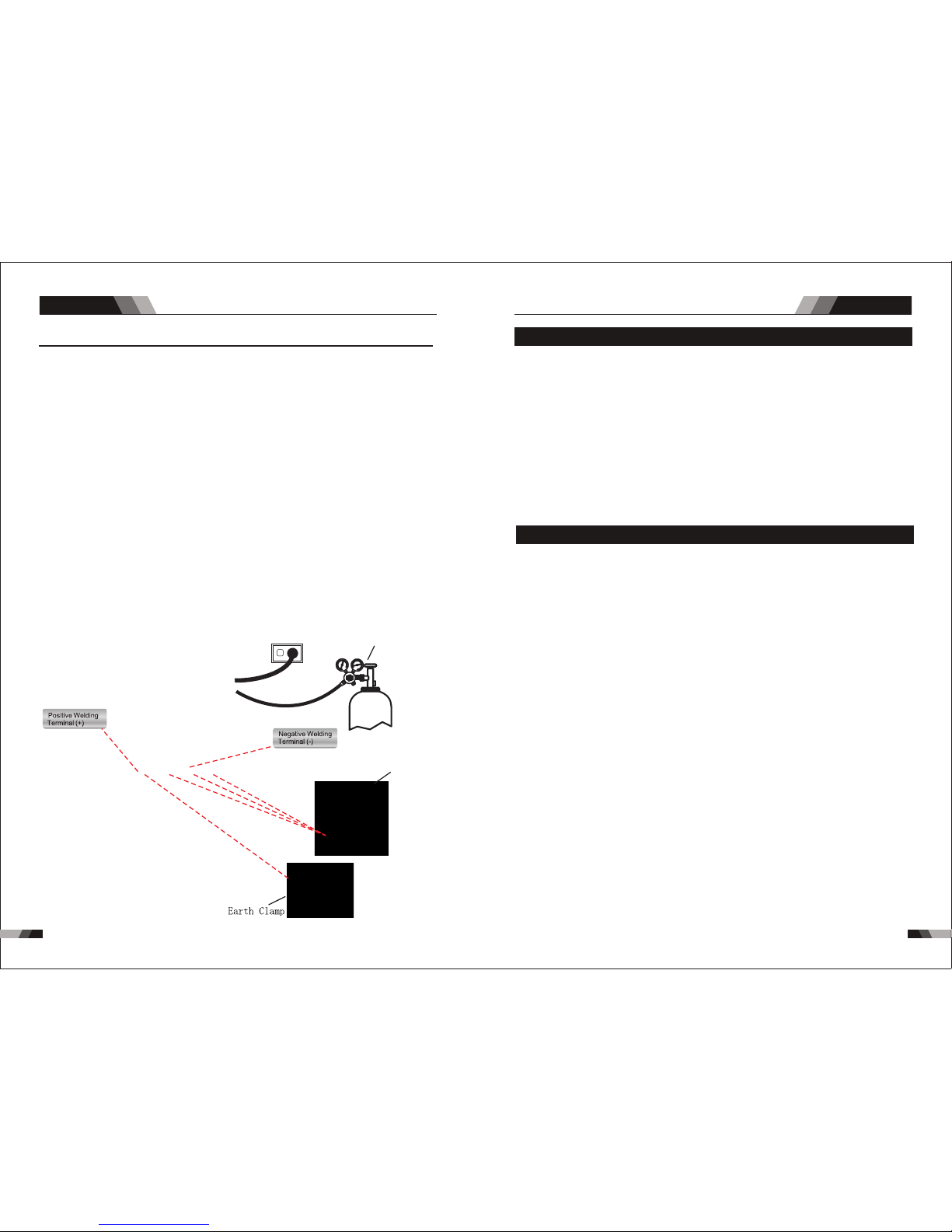
The f ollow ing set u p is know n as Stra igh t Pola rity o r DC elec trode p ositi ve. Thi s is
com monly u sed for D C LIFT TI G weld ing on m ost mat erial s such as s teel an d stain less
ste el.
1. Sw itch th e ON/OF F Swi tch (l ocat ed on t he rea r pane l) to OFF.
2. Co nnect t he work l ead cab le to the p ositi ve outp ut term inal, a nd the LI FT TIG Torch
cab le to the n egati ve outp ut term inal.
3. Co nnect t he gas li ne/ho se to the p roper s hield ing gas s ource .
4. Sl owly op en the Arg on Cyli nder Val ve to th e fully o pen positi on.
5. Co nnect t he work l ead cla mp to you r work pi ece.
6. Th e tung sten mu st be gro und to a bl unt poi nt (sim ilar to a p encil ) in orde r to achi eve
opt imum we lding r esult s. See il lustr ation . It is cri tic al to gr ind th e tun gste n elec trode
in th e direc tion th e grind ing whe el is tur ning. G rind at a 3 0 degre e angle a nd neve r
to a sh arp poi nt.
7. In stall t he tung sten wi th appr oxima tely 1. 6mm to 3. 2mm s tick ing ou t from th e
gas c up, ens uring y ou have c orrec t sized c ollet .
8. Tig hten th e back ca p.
9. Tur n the swi tch to th e “ON” po sitio n. The po wer L. E.D. li ght sho uld ill umina te.
10. S et the we lding p roces s to LIFT T IG.
11. Se t the We ld Cur rent Co ntrol K nob to th e desir ed ampe rage.
12. You are no w read y to begin LI FT TIG We lding.
pow er supp ly
Ar./ GAS(T IG/WI G)
TIG torc h
NO TE
3130
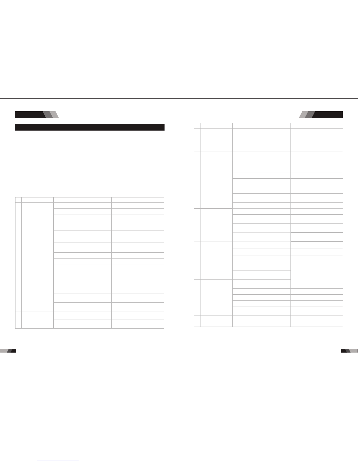
3.1 Troubleshoo ting
◆Bef ore arc w eldin g machi nes are d ispat ched fr om the fa ctory, t hey ha ve alre ady bee n
deb ugged a ccura tely. So f orbi d anyon e who is no t autho rized b y us to do an y chang e to
the e quipm ent!
◆Mai ntena nce cou rse mus t be oper ated ca reful ly. If any w ire be comes f lexib le or is
mis place d, it may be pote ntial d anger t o user!
◆Onl y profe ssion al main tenan ce pers onal wh o is auth orize d by us cou ld overhau l the
mac hine!
◆Gua rante e to shut o ff the ar c weld ing mac hine’ s power bef ore tu rn on the out line o f
the e quipm ent!
◆If th ere is an y probl em and ha s no the au thori zed pro fessi onal ma inten ance pe rsona l,
ple ase con tact lo cal age nt or the b ranch c ompan y!
If th ere a re som e simp le tr oubl es of V-s eries w eldin g machi ne, you c an cons ult the
fol lowin g overh aulin g chart :
Nr.
Nr.
1
7
8
9
10
11
2
3
4
5
6
Troubles
Troubles
AC/DC SERIES EQUIPMENT
AC/DC SERIES EQUIPMENT
Tro ubles hooti ng Tro ubles hooti ng
Solution
Solution
Fan is broken
The welding cable is not connected
with the two output if the welder
Connect the welding cable to
the welder's output
The power board is broken
The power cable is broken
There is something in the fan
The welding cable is damaged
The earth cable connected unstably
The welding cable is too long
Input voltage not stable
There is oil or dust on the workpiece
Gas cylinder is close or gas
pressure is low
The HF igniting board does not work
Something is in the valve
Check if the function selected MMA
Change the function to TIG
Check the HF funtion is selected Select the HF funtion
HF board is broken
Earth clamp connect not stable
Repair or change it
Check the earth clamp
Open or change the gas cylinder
Remove it
Remove it
Change it
Change it
Change it
The distance between discharge r is
too short or too long
The malfunctio n of the welding gun
switch
No argon gas flow or the air tube
connect not good
No argon gas flow or the air tube
connect not good
Pressure too high or air regulator is
broken
There is no Argon flow or the
connectio n is poor
The distance between tungsten
electrode and workpiece is too long
Repair or change it
Check the earth cable
Use an appropriate welding cable
Check the power supply
Check and remove it
Reduce the distance
(about 3mm ,less than 5mm)
Check and reconnect
Repair or change it
Adjust the distance (about 0.8mm)
Check the welding torch switch,
control cable and aero socket.
Check and reconnect
Check and reconnect
Check gas
The start capacitor of fan damaged
Tur n on the p ower
sou rce, po wer
ind icato r is lit, f an
is no t worki ng.
Arc c an not be
ign ited (T IG) ,
the re is spa rk
on th e HF
ign iting b oard
Arc c an not be
ign ited (T IG) ,
the re is no sp ark
on th e HF
ign iting b oard
Tur n on the
pow er sour ce,
eve rythi ng is
nor mal , but n o
HF ig nitin g
No ga s flow (T IG)
Gas a lways f lows
Tur n on the
pow er sour ce,
fan i s worki ng,
pow er indi cator
is no t lit
Tur n on the p ower
sou rce, fa n is not
wor king ,p ower
ind icato r is not li t
Tur n on the p ower
sou rce, po wer
ind icato r is lit, f an
is wo rking , there
is no w eldin g
out put.
The n umber o f the
dis play is n ot
int act
No no -load
vol tage ou tput
(MM A)
Reasons
Reasons
Cha nge fan
Cle an it
Cha nge cap acito r
The p ower li ght dam aged or
con necti on is not g ood
The p ower ca ble con necte d not
goo d
Con trol bo ard is br oken
st
1 in verte r circu it dama ged
nd
2 fee dback c ircui t is faul t
Dig ital tu be is bro ken
The d ispla y panel i s damag ed
If th e overh eat ind icato r is on
The m ain cir cuit is b roken
The m achin e is brok en
Cha nge the d ispla y panel
Display panel is broken
The light of the power indicator is
broken and the problems
mentioned in Nr. 2
Change the light of the power
indicator or refer to the solution
in Nr. 2
Cha nge it
Cha nge it
Cha nge it
Cha nge it
Rep air or ch ange it
Cha nge the p ower li ght
Con nect co rrect ly
Pow er on swi tch is da maged
The p ower bo ard is br oken
Cha nge it
Rep lace it
Cha nge it
Cha nge it
Wait a few minutes, the machine
can b e opera ted nor mal
Che ck and re pair
Con sult th e deale r or the
man ufact urer
Elec tromagn etic valv e is damaged
Air tub e is brocken
Some thing is in the va lve
Elec tromagn etic valv e is damaged
3332
AC/DC SERIES EQUIPMENT
Tro ubles hooti ng
STICK SERIES EQUIPMENT
CHAPTER 2
STICK SERIES EQUIPMENT
E-S eries
Nr.
16
17
18
Troubles
Solution
Over-heat prot ection ,too much
welding curren t
Reduce the welding current
Reduce the welding time
Over-heat prot ection ,working too
much time
Over-curr ent protection, current in
the main circuit is out of control
Tig torch is connected to the
positive termi nal
Tungsten electrod e is too big for
the welding current
Check the earth clamp position on
the work piece
Check and repair main circuit
and drive board
Connect the tig torch to negative
terminal
Adjust the position of earth clamp
Select the correct size of tungsten
electrode
Thermal overload
indicator light is on
Tig electrode melts
when welding
Arc flutters during
Tig welding
Reasons
15
The p enetr ation
of mo lten po ol is
not e nough
Adj ust the d istan ce from t orch
to wo rk piec e
Use t he suit able le ngth fr om
man ufact urer
Inc rease t he weld ing cur rent
The w eldin g curre nt is adj usted
too l ow
The a rc is too l ong in th e weldi ng
pro cess
The p ower ca ble or th e weldi ng
cab le is too l ong
12
Checking if the electorde stick to
the work piece that the anti-stick
function is on
Repair or change it
Repair or change it
Change to suitable setting
The w eldin g
cur rent ca nnot
be ad juste d
Cont rol board is br oken
Cont rol board is br oken
AC Width adjustment is not correct
Shut off the power when changing the tor ch
Sep arate t he elec trode a nd
wor k piece
13
14
Repair or change it
Check the power supply
Change the fan
Change it
Change it
No AC ou tput
whi le sele cting
"AC "
The w eldin g
cur rent di splay ed
isn 't acco rdant
wit h the act ual
val ue
The pow er board is bro ken
Inpu t voltage is to o low
Fan is bro ken
The AC drive boar d damaged
The AC IGBT/IGBT module damaged
The m in valu e displ ayed is n't
acc ordan t with th e actua l value
Adj ust pot entio meter I min on
the c ontro l board
Adj ust pot entio meter I min on
the c ontro l board
The m ax valu e displ ayed is n't
acc ordan t with th e actua l value
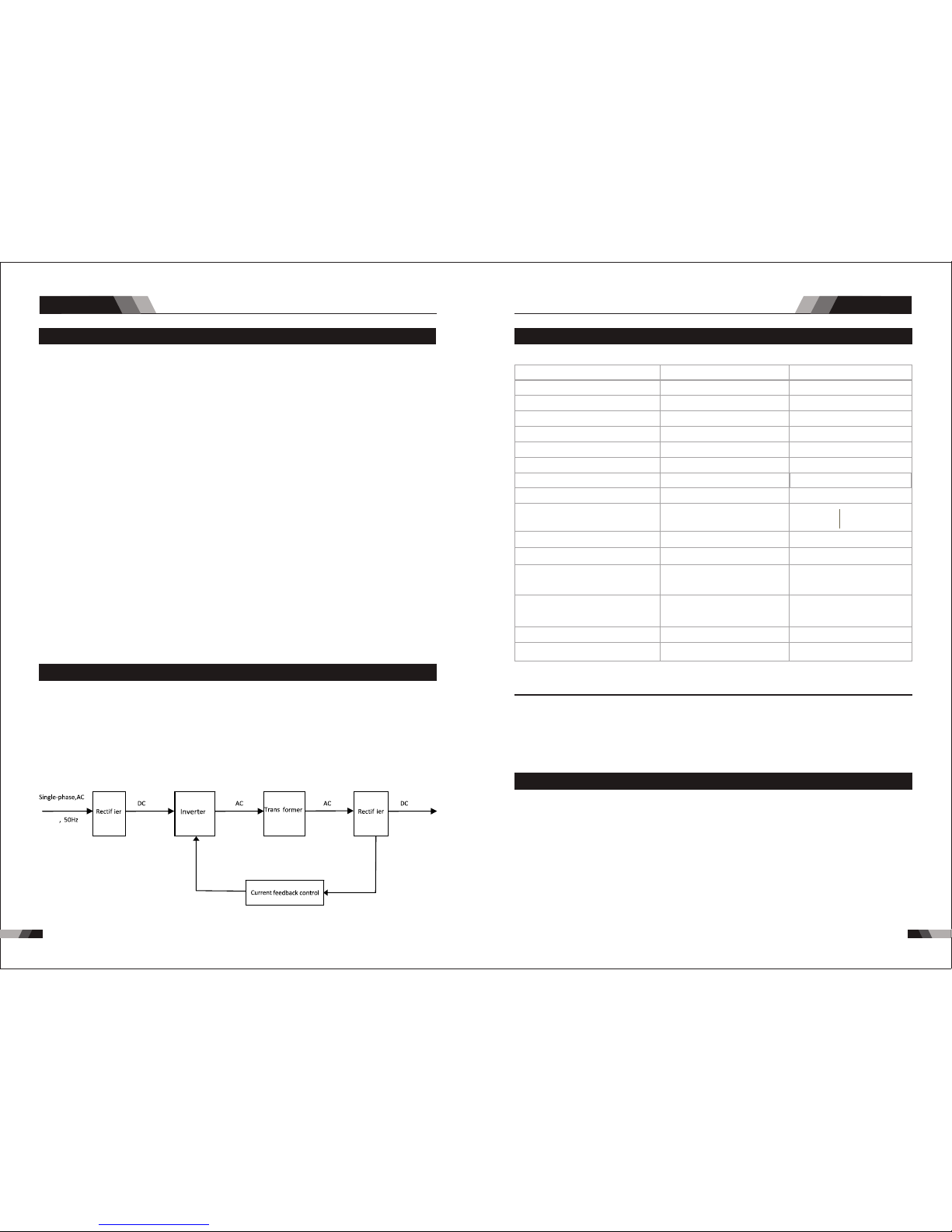
◆
occ oure d, the a larm la mp on th e fron t panel will be o n and th e outpu t curr ent wi ll
be cu t off. It can sel f-pr otec t and pr olong the usi ng lif e.
In tel li gen t pr ote cti on: o ver -cu rr ent , ov er- hea t, wh en t he m ent ion ed pr obl ems
3534
STICK SERIES EQUIPMENTSTICK SERIES EQUIPMENT
Sum mary
Sum mary
1.1 Brief I ntrod uctio n
E16 1, E201 , E221, E 301 , E401 w eldi ng mach ines ad opts th e lat est pu lse wi dth
mod ulati on (PWM ) techn ology a nd insu lated g ate bip olar tr ansis tor (IG BT) pow er modu le,
whi ch can ch ange wo rk freq uency t o mediu m frequ ency so a s to repl ace the t radit ional
hul king wo rk freq uency t ransf ormer w ith the c abine t mediu m frequ ency tr ansfo rmer. Th us,
its c harac teriz ed with p ortab le, sma ll size , light w eight , low con sumpt ion and e tc.
E16 1,E20 1,E22 1,E30 1,E40 1 STICK m achin es Char acter istic s:
◆MCU c ontro l syste m, resp onds im med iate ly to an y cha nges .
◆hi gh vo lta ge f or a rc igni ti ng to ens ure t he su cce ss r at io of ign iti ng a rc.
◆Lif t TIG ope rat ion, I f the tu ngs ten el ectr ode t ouch es the w ork piec e when w eld ing,
the c urren t will dr op to s hort -cir cui t curr ent to p rot ect tu ngst en.
◆Ped al cont rol the w eld ing cu rren t.
◆IN DC T IG oper ati on ele ctro de to uche s the wo rkp iece w hen we ldi ng, th e curr ent
wil l dro p to sho rt-c irc uit cu rren t to pr otec t tung ste n.
◆
pie ce more t han 2 sec onds, t hus t he out put cu rre nt com e down t o aro und 20 A in
ord er to eas ily sep erate t he elec trode a nd el ectr ode ho lde r to pro tect t he we lder .
1.3 Specificat ions E1 61/E201
IP2 3
Des cript ion
Wei ght
Pow er Sour ce Dime nsion s
Coo ling
Wel der Typ e
Eur opean S tanda rds
Num ber of Ph ases
Nom inal Su pply Vol tage
Nom inal Su pply Fr equen cy
Wel ding C urrent Ran ge
( STI CK Mode )
Sin gle Pha se Gene rator
Req uirem ent
STI CK (MMA )
Wel ding O utput , 40ºC, 1 0 min.
Ope n circu it volt age
Pro tecti on Clas s
Max imum In put Cur rent
Effective Input Current
VEC TOR DIG ITAL E20 1 STICK
10 kg
H39 0mmxW 180mm xD390 mm
Fan C ooled
Inv erter P ower So urce
EN 60 974-1 / I EC 6097 4-1
1
230 V +/- 15%
50/ 60Hz
20 - 20 0A
22. 8A
41. 7A
14. 4kVA
200 A @30 %, 28V
110A @ 10 0%, 24 .4V
66V D C
IP2 3
VEC TOR DIG ITAL E16 1 STICK
9.6 kg
Fan C ooled
Inv erter P ower So urce
EN 60 974-1 / I EC 6097 4-1
1
230 V +/- 15%
50/ 60Hz
10 - 16 0A
19. 8A
31. 4A
10. 8KVA
160 A @ 40% , 26. 4V
101 A @10 0%, 24 V
66V D C
H39 0mmxW 180mm xD390 mm
NO TE
Due t o variation s that c an occu r in man ufac tured p rodu cts, claime d perf orma nce, vo ltag es,
rat ings , all cap acit ies, measur emen ts, di mensi ons an d weig hts quo ted ar e approxima te
onl y. Ach ievable cap acit ies and ratin gs in use and ope rati on will d epen d upon co rrec t
ins tall atio n, use, a ppli cati ons, ma inte nanc e and ser vice .
◆200 Am p elect rode ho lder wi th 3M cab le
◆200 Am p earth c lamp wi th 3M cab le
◆3M Po wer cab le
◆Ope ratin g Manua l
1.4 Packa ged Ite ms
E161/E2 01
1.2 Wor king Pr inciple
230V
The w orki ng prin ciple o f E161/ E201/ E221/ E301/ E401 we lding m achin es is sho wn as
the f ollow ing fig ure. Si ngle- phase 2 30V wor k frequ ency AC is r ectif ied int o DC(ab out
312 V ), then i s conve rted to m edi um fre quen cy AC (abo ut 20-4 0KHz) b y inver ter dev ice
(IG BT modu le), a fter re ducin g volta ge by med ium tra nsfor mer (th e main tr ans form er) an d
Mea nwhil e, the we lding c urren t param eter ca n be adju sted co ntinu ously a nd step lessl y
to me et the re quire ments o f weldi ng craf t.
Ant i-Sti ck func tio n auto mati cal ly app eare d whe n the el ectr ode s tick t o the wo rk
re ctifyin g by me dium f req uen cy re ctif ier (f ast r eco ver y dio des) ,the n is ou tpu tte d DC .T he
ci rc ui t ad op ts c ur re nt f ee db ac k co nt ro l te ch no log y to in su re cu rr en t ou tp ut s ta bl y.
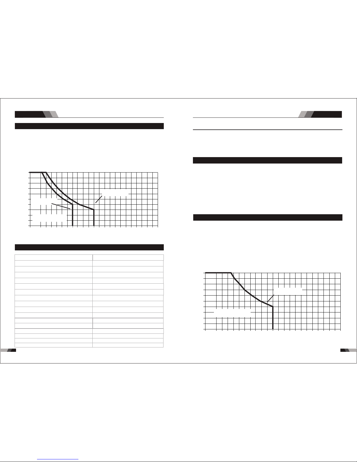
3736
1.5 Duty Cy cle
The r ated d uty cyc le of a We ldi ng Pow er Sou rce is a st ateme nt of the t ime i t may be
ins ulati on of the c ompon ent par ts. To expl ain th e 10 minu te duty c ycle pe riod th e follo wing
exa mple is u sed. Su ppose a W eldi ng Powe r Sourc e is desi gned to oper ate at a 4 0% duty
cyc le, 200 a mpere s at 28 vol ts. Thi s mean s that it h as been d esign ed and bu ilt to pr ovide
the r ated am perag e (200A ) for 4 min ute s, i.e . arc we ldi ng tim e, out o f eve ry 10 mi nute
the W eldi ng Powe r Sourc e must id le and be a llowed to co ol.
STICK SERIES EQUIPMENTSTICK SERIES EQUIPMENT
Duty Cyc le(P ERC ENTAG E)
Welding Cu rrent(AM PS)
10 0 120 14 0 160 18 0 20 0 22 0
0
10
20
30
40
50
60
70
80
90
10 0
24 0 2 60 28 0 3 00 3 200
E20 1 STICK
E16 1 STICK
Saf e Opera ting Re gion
(ST ICK)
ope rate d at its r ated w eldi ng cur rent o utput without exc eedi ng the t empe ratu re lim its of t he
per iod (4 0% of 10 mi nute s is 4 minu tes) . Duri ng the other 6 mi nute s of the 10 m inut e period
1.8 Duty Cy cle
The r ated d uty cyc le of a We ldi ng Pow er Sou rce is a st ateme nt of the t ime i t may be
ins ulati on of the c ompon ent par ts. To expl ain th e 10 minu te duty c ycle pe riod th e follo wing
exa mple is u sed. Su ppose a W eldi ng Power Sou rce is d esigned t o oper ate at a 40% du ty
the r ated am perag e (200A ) for 4 min ute s, i.e . arc we ldi ng tim e, out o f eve ry 10 mi nute
the W eldi ng Powe r Sourc e must id le and be a llowed to co ol.
Duty Cyc le( PERCENTA GE)
Weldi ng Curr ent(A MPS)
10 0 12 0 14 0 16 0 18 0 2 00 2 20
0
10
20
30
40
50
60
70
80
90
10 0
24 0 26 0 28 0 30 0 32 00
E22 1 STICK /TIG
Saf e Opera ting Re gion
(TI G&STI CK)
ope rate d at its r ated w eldi ng cur rent o utpu t with out ex ceed ing th e temp erat ure li mits o f the
cy cle, 200 a mper es at 28 v olts . Thi s mea ns th at it h as be en de sign ed and b uilt t o pro vid e
per iod (4 0% of 10 minute s is 4 min utes ). Dur ing the other 6 m inut es of the 10 minu te per iod
1.7 Packa ged Ite ms
◆200 A ele ctrod e holder wit h 3M cab le.
◆200 A ear th clam p with 3M c able
◆4M TI G Torch WP2 6
◆3M Po wer cab le
◆Ope ratin g Manua l
E221
NOTE
Due t o varia tion s that can occu r in manu fact ured p roduc ts, cl aimed perfo rman ce, vol tage s,
rat ings , all cap acit ies, me asur ements, dim ensi ons and w eigh ts quot ed are a pproximat e
onl y. Ach ievab le cap acities and r atin gs in use a nd oper atio n will de pend u pon correct
ins tall ation, use, a pplicatio ns, ma intenance a nd service.
Wel ding O utput , 40ºC, 1 0 min. TI G
200 A @ 40% , 18V 12 6A @ 100%,15 V
Des cript ion
Wei ght
Pow er Sour ce Dime nsion s
Coo ling
Wel der Typ e
Eur opean S tanda rds
Num ber of Ph ases
Nom inal Su pply Vol tage
Nom inal Su pply Fr equen cy
Wel ding C urren t Range ( STIC K/ TIG M ode)
Sin gle Pha se Gene rator R equir ement
Wel ding O utput , 40ºC, 1 0 min. ST ICK (MM A)
Max imum In put Cur rent
Effective Input Current
VEC TOR DIG ITAL E22 1 STICK
10. 59 k g
Fan C ooled
Inv erter P ower So urce
EN 60 974-1 / I EC 6097 4-1
1
230 V +/- 15%
50/ 60Hz
10 - 20 0A/5- 170A
26. 3A
41. 7 A
14. 4KVA
200 A @ 40% , 28V 12 6A @ 100%, 25V
H39 0mmxW 180mm xD390 mm
Ope n circu it volt age
66V D C
IP2 3
Pro tecti on Clas s
1.6 Specificat ions E2 21
Sum mary Summa ry
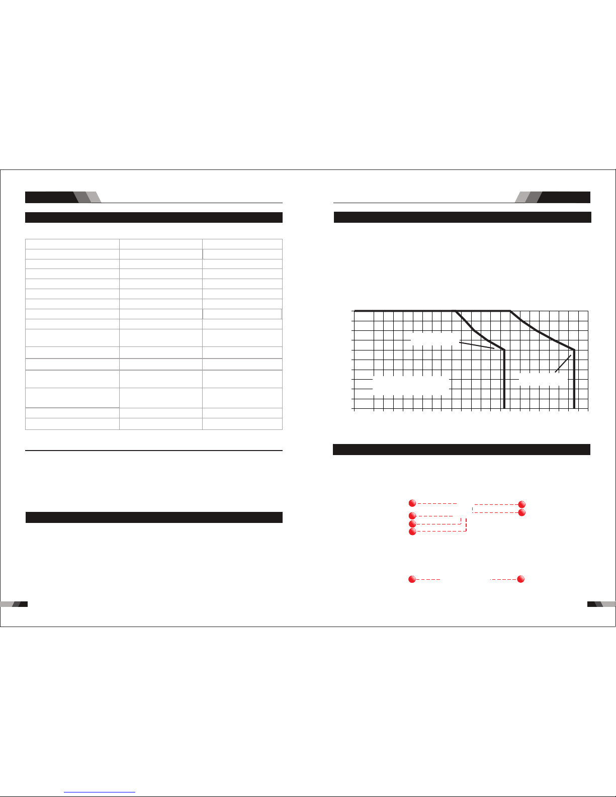
38
39
Sum mary Summa ry
STICK SERIES EQUIPMENTSTICK SERIES EQUIPMENT
2.1 Layout For The P anel E1 61 /E201
11
22
88
66
33
44
55
77
1.11 Duty Cy cle
The r ated d uty cyc le of a We ldi ng Pow er Sou rce is a st ateme nt of the t ime i t may be
ins ulati on of the c ompon ent par ts. To expl ain th e 10 minu te duty c ycle pe riod th e follo wing
exa mple is u sed. Su ppose a W eldi ng Powe r Sourc e is designe d to ope rate at a 60% d uty
the r ated am perag e (400A ) for 6 min utes, i .e. a rc wel ding t ime , out of e very 1 0 min ute
per iod (60 % of 10 min utes is 6 m inute s).Du ring th e other 4 m inute s of the 10 m inute p eriod
the W eldi ng Powe r Sourc e must id le and be a llowed to co ol.
ope rate d at its r ated w eldi ng cur rent output without exc eedi ng the t empe ratu re lim its of t he
cy cle, 400 a mper es at 36 v olts . Thi s mea ns th at it h as be en de sign ed and b uilt t o pro vid e
Duty Cyc le( PERCENTA GE)
Weldi ng Curr ent(A MPS)
10 0 13 0 160 1 90 2 20 250 2 80
0
10
20
30
40
50
60
70
80
90
10 0
310 3 30 3 60 3 90 4 200
E40 1 STICK
E30 1 STICK
Saf e Opera ting Re gion
(ST ICK)
1.10 Pack aged It ems
◆300 A ele ctrod e holder wit h 3M cab le
◆300 A ear th clam p with 3M c able
◆3M Po wer cab le
◆Ope ratin g Manua l
E301/E401
1.9 Specificat ions E3 01/E401
IP2 3
Des cript ion
Wei ght
Pow er Sour ce Dime nsion s
Coo ling
Wel der Typ e
Eur opean S tanda rds
Num ber of Ph ases
Nom inal Su pply Vol tage
Nom inal Su pply Fr equen cy
Wel ding C urrent Ran ge
( STI CK Mode )
Sin gle Pha se Gene rator
Req uirem ent
STI CK (MMA )
Wel ding O utput , 40ºC, 1 0 min.
Ope n circu it volt age
Pro tecti on Clas s
Max imum In put Cur rent
Effective Input Current
VEC TOR DIG ITAL E40 1 STICK
26. 3 kg
H54 0mmxW 235mm xD445 mm
Fan C ooled
Inv erter P ower So urce
EN 60 974-1 / I EC 6097 4-1
3
400 V +/- 15%
50/ 60Hz
30 - 40 0A
20. 4A
26. 3A
27. 3kVA
66V D C
IP2 3
VEC TOR DIG ITAL E30 1 STICK
19. 2 kg
Fan C ooled
Inv erter P ower So urce
EN 60 974-1 / I EC 6097 4-1
3
400 V +/- 15%
50/ 60Hz
30 - 30 0A
13. 6A
17. 5 A
18. 2KVA
66V D C
H51 5mmxW 224mm xD375 mm
300 A @ 60% , 32V
232 A @ 100 %, 29. 3V
400 A @ 60% , 36V
310 A @ 100 %, 32. 4V
Due t o varia tions t hat can o ccur in m anufa cture d produ cts, cl aimed p erfor mance ,volt ages,
rat ings, a ll capa citie s, meas ureme nts, di mensi ons and w eight s quote d are app roxim ate
onl y. Achi evable cap acit ies and rat ings i n use and ope rati on will dep end up on correc t
ins talla tion, u se, app licat ions, m ainte nance a nd serv ice.
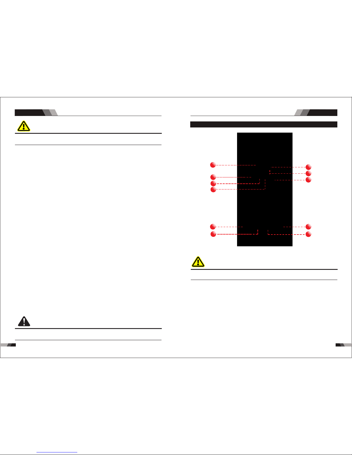
40
41
Ope ratio n
STICK SERIES EQUIPMENTSTICK SERIES EQUIPMENT
1. Power I ndi cat or
The g reen p ower indica tor wi ll be il lumi nated when th e weld er is turned ON a nd ind icat es
the p rese nce of po wer.
DO NO T TOU CH the e lectrod e wire w hile it is be ing fe d through t he sys tem. The electr ode
wir e will be a t weldi ng volt age pot entia l.
WAR NIN G
2. Therm al Ov erl oad Indic ato r Lig ht
Thi s weld ing pow er sour ce is pro tecte d by a self r esett ing the rmost at. The i ndic ator wi ll
illumi nat e if the d uty c ycle o f the p ower s ourc e has be en ex ceed ed. S houl d the th erma l
ov erl oad indic ator i llu min ate t he output o f the po wer s our ce wi ll be d isa ble d. Once the
po wer s our ce cools down th is lig ht wi ll go O FF an d the o ver t emp era tur e con diti on wil l
au tomatic all y res et. N ote th at the m ain s pow er sw itch s houl d rem ain i n the o n posi tion
su ch that the f an con tin ues t o oper ate th us al low ing th e unit t o coo l suff icie ntl y. Do not
swi tch the u nit off s houl d a therm al over load co nditi on be pre sent.
2.2 Layout For The P anel E2 21
11
22
3
10
11
5
4
7
6
9
8
1. Power I ndi cat or
The g reen p ower i ndic ator w ill be i llum inat ed when the wel der is t urne d ON and i ndic ates
the p rese nce of p ower.
3.Digi tal D isp lay
The digi tal m eter i s used t o display t he pr e-se t (pr eview) am per age fo r wel ding, the
preset p ara mete rs in H ot st art, s tar t time a md Arc fo rce a nd act ual w eldi ng amp erag e of
the powe r sou rce wh en wel ding .
4.Sele cti ng Fu nction Bu tto n
Pre ss and re lease t his but ton to ch ange th e selec ted wel d funct ions mo de from w eldin g
cur rent to h otsta rt to sta rt ti me to ARC F orce f rom t he dig ital d isp lay.
5.Posi tiv e Con trol
The p ositi ve cont rol is us ed to plu s setti ng para meter f or sele cted fu nctio n from 4.
6.Nega tiv e Con trol
The n egati ve cont rol is us ed to min us sett ing par amete r for sel ected f uncti on from 4 .
7. Negat ive W elding Ou tpu t Termi nal
The n egati ve weld ing ter minal i s used to c onnec t the wel ding ou tput of t he powe r sourc e
to th e appro priat e weldi ng acce ssory s uch as el ectro de hold er. It is es senti al, how ever,
tha t the mal e plug is i nse rted a nd tur ned s ecur ely to a chiev e a sound e lec tric al
con necti on.
CA UTI ON
DO NO T TOU CH the e lectrod e wire w hile it is be ing fe d through t he sys tem. The electr ode
wir e will be a t weldi ng volt age potent ial.
Loo se weld ing ter minal c onnectio ns can c ause over heat ing and res ult in t he male plu g
bei ng fuse d in the ba yonet t ermin al.
8. Posit ive W elding Ou tpu t Termi nal
The p ositive w eldi ng ter mina l is use d to con nect t he weldin g outp ut of th e powe r sour ce
to th e appr opr iate w eldi ng acc esso ry suc h as ear th clamp. I t is ess enti al, ho weve r, that
the m ale pl ug is inser ted an d turn ed sec urel y to ach ieve a soun d elec tric al con nect ion.
2. Therm al Ov erl oad Indic ato r Lig ht
Thi s weld ing pow er sour ce is pro tecte d by a self r esett ing the rmost at. The i ndic ator wi ll
illumi nat e if the d uty c ycle o f the p ower s ourc e has be en ex ceed ed. S houl d the th erma l
ov erl oad indic ator i llu min ate t he output o f the po wer s our ce wi ll be d isa ble d. Once the
po wer s our ce cools down th is lig ht wi ll go O FF an d the o ver t emp era tur e con diti on wil l
au tomatic all y res et. N ote th at the m ain s pow er sw itch s houl d rem ain i n the o n posi tion
su ch that the f an con tin ues t o oper ate th us al low ing th e unit t o coo l suff icie ntl y. Do not
swi tch the u nit off s houl d a therm al over load co nditi on be pre sent.
Set ting ra nges
Arcfor ce: 1-1 00AMP Hot S tart:0.1-0 .5S H otstart curr ent :1-100 AMP
WAR NIN G
Ope ratio nOpe ratio n

42 43
2.3 Layout For The P anel E3 01/E401
11
22
3
4
9
5
7
6
8
10
1. Power I ndi cat or
The g reen p ower indica tor wi ll be il lumi nated when th e weld er is turned ON a nd ind icat es
the p rese nce of po wer.
WAR NIN G
DO NO T TOUCH t he ele ctro de wir e whil e it is be ing fe d thro ugh th e syst em. Th e elec trod e
wir e will b e at wel ding v olta ge pot ential.
3.Prev ent E lec tric Shoc k
The V RD butt on on the f ront pa nel is il lumin ated wh en pres sing th e VRD ind icato r, at the
sam e time th e no- load v olta ge is low er than 1 5V and th e outpu t termi nal is no t harmf ul
to th e hum an bod y.Whe n the bu tton is p res sed ag ain, t he VRD in dicat or ligh t goes ou t,
and t he outp ut is now a t 71V.
Ope ratio n
STICK SERIES EQUIPMENTSTICK SERIES EQUIPMENT
2. Therm al Ov erl oad Indic ato r Lig ht
Thi s weld ing pow er sour ce is pro tecte d by a self r esett ing the rmost at. The i ndic ator wi ll
illumi nat e if the d uty c ycle o f the p ower s ourc e has be en ex ceed ed. S houl d the th erma l
ov erl oad indic ator i llu min ate t he output o f the po wer s our ce wi ll be d isa bled. Once the
po wer s our ce cools down th is lig ht wi ll go O FF an d the o ver t emp era tur e con diti on wil l
au tomatic all y res et. N ote th at the m ain s pow er sw itch s houl d rem ain i n the o n posi tion
su ch that the f an con tin ues t o oper ate th us al low ing th e unit t o coo l suff icie ntl y. Do not
swi tch the u nit off s houl d a therm al over load co nditi on be pre sent.
5.Nega tiv e Con trol
The n egati ve cont rol is us ed to min us sett ing par amete r for sel ected f uncti on from 6 .
6.Sele cti ng Fu nction Bu tto n
Pre ss and r elease this but ton to c hang e the se lect ed wel d func tion s mode f rom we ldin g
cur rent t o hots tart to start tim e to ARC Force fr om the d igit al dis play.
7.Posi tiv e Con trol
The p ositi ve cont rol is us ed to plu s setti ng para meter f or sele cted fu nctio n from 6.
8. Negat ive W elding Ou tpu t Termi nal
The n egat ive we ldin g term inal i s used t o conn ect th e weld ing ou tput o f the po wer so urce
to th e appr opri ate we ldin g acce ssor y such a s elec trod e hold er. It is e ssen tial , howe ver,
tha t the ma le plu g is ins erte d and tu rned s ecur ely to a chie ve a sou nd ele ctri cal
con nect ion.
9. Shiel din g Gas O utletl
The S hielding Ga s Outle t loca ted on th e front p anel i s a fast co nnect ion of a su itab le TIG
Torch .
10. 5 Pin Co ntr ol So cket
The 5 p in rece ptac le is use d to conn ect a tri gger s witch o r remote cont rol to th e weld ing
Pow er Source cir cuitry.
To make conn ection s, align keyway, inse rt plug, an d rotate threade d collar fu lly cloc kwise.
11. Posit ive W elding Ou tpu t Termi nal
The p osit ive we ldin g term inal i s used to conne ct the w eldi ng out put of t he pow er sou rce
to th e appr opri ate we ldin g acce ssor y such as earth c lamp . It is es sent ial, h owev er, tha t
the m ale pl ug is in sert ed and turned secur ely to a chie ve a sou nd ele ctri cal co nnec tion .
CA UTI ON
Loo se weld ing ter minal c onnectio ns can c ause over heat ing and res ult in t he male plu g
bei ng fuse d in the ba yonet t ermin al.
3.Weld P roc ess Selec tio n Button
Pre ss and re lease t his but ton to ch ange th e selec ted wel d proce ss mode f rom LIF T TIG
to ST ICK. Th e weld p roces s will ch ange to t he next p roces s in the se quenc e each ti me
to id entif y LIFT TI G or STI CK pro ces s mode .
4.Digi tal D isp lay
The d igita l meter i s used to d isp lay th e pre- set (pr evi ew) am pera ge for we lding , the
pre set par amete rs in Hot s tart, s tar t time a md Arc fo rce a nd act ual we lding a mpera ge of
the p ower so urce wh en weld ing.
Ope ratio n
the b utto n is pres sed and relea sed. Th e gree n indic ator s next to t he button wil l illu minat e

44
45
4.Sele cti ng Fu nction Bu tto n
Pre ss and re lease t his but ton to ch ange th e selec ted wel d funct ions mo de from w eldin g
cur rent to h ots tart t o star t tim e to ARC Fo rce fr om th e digi tal di spl ay.
6.Nega tiv e Con trol
The n egati ve cont rol is us ed to min us sett ing par amete r for sel ected f uncti on from 4 .
7.Posi tiv e Con trol
The p ositi ve weld ing ter minal i s used to c onnec t the wel ding ou tput of t he powe r sourc e
to th e appro priat e weldi ng acce ssory s uch as el ectro de hold er. It is es senti al, how ever,
8.Posi tiv e Welding O utp ut Term ina l
The p ositi ve cont rol is us ed to plu s setti ng para meter f or sele cted fu nctio n from 4.
9.Nega tiv e Welding O utp ut Term ina l
The p ositi ve weld ing ter minal i s used to c onnec t the wel ding ou tput of t he powe r sourc e
to th e appro priat e weldi ng acce ssory s uch as ea rth cla mp. It is e ssent ial, ho wever, that
the m ale plu g is inse rted an d turne d secur ely to ac hie ve a sou nd ele ctric al
con necti on.
10. 5 Pin Co ntr ol So cket
The 5 p in rec eptacle is us ed to co nnect a trigg er swi tch or re mote c ontr ol to th e weldi ng
Pow er Sou rce ci rcuitry.
To make c onnec tions , align k eyway, i nser t plug, a nd rota te th read ed col lar ful ly
clo ckwis e.
CA UTI ON
CA UTI ON CA UTI ON
Loo se weld ing ter minal c onnectio ns can c ause over heat ing and res ult in t he male plu g
bei ng fuse d in the ba yonet t ermin al.
2.4 Set-up F or LI FT TI G (GTAW) Welding (only for E221)
Bef ore any w eldin g is to beg in, be su re to wea r all app ropri ate
and r ecomm ended s afety e quipm ent.
Bef ore any w eldin g is to beg in, be su re to wea r all app ropri ate
and r ecomm ended s afety e quipm ent.
NO TE
NO TE
The f ollow ing ste ps will a ssume t hat you h ave alr eady se t up the pr oper sh ieldi ng gas as
out lined i n Sub Sec tion
Th e fol lowi ng set u p is kn own a s Str aig ht Po lari ty or DC E lect rod e Pos itiv e. Thi s is
co mmon ly use d for D C LIF T TIG weldi ng on m ost m ate ria ls su ch as s teel and st ainl ess
st eel.
1.S witch t he ON/O FF Swit ch (l ocat ed on th e rea r pane l) to OF F.
2.C onnec t the wor k earth c lamp to t he po siti ve out put t ermi nal, a nd the LI FT TIG Torch
cab le to the n egati ve outp ut term ina l. Ref er to Fi gure 5- 02.
3. Con nec t the gas l ine /ho se to the p rop er shie ldi ng ga s sou rce a nd co nne ct the av iat ion
pl ug fo r tri gge r swi tch t o 5 pin c ont rol sock et Re fer t o Fig ure 5 -02 .
4.S lowly o pen the Ar gon Cyl inder Valve to t he full y open posit ion.
5.C onnec t the wor k earth c lamp to y our wor k piece .
6.T he tung sten mu st be gro und t o a blun t poin t (simi lar t o a penc il) in o rder to a chiev e
opt imum we lding r esult s. (Ref er to F igur e: 5-0 1). I t is cri tica l to gr ind th e tung ste n
ele ctrod e in the di recti on the gr indin g wheel i s turni ng. Gri nd at a 30 de gree an gle and
nev er to a sha rp poin t.
7.I nstal l the tun gsten w ith app roxim ately 1 .6mm to 3 .2m m stic king o ut fr om the g as cup ,
ens uring y ou have c orrec t sized c ollet .
Fig ure:5 -01
8.T ight en the b ack cap .
9.T urn th e swit ch to the “ ON” pos ition . The p ower L. E.D. li ght sho uld ill umina te.
10. Set the w eldin g proce ss to LIF T TIG .
11.S et the W eld Cu rrent f rom the p ositi ve and ne gativ e contr ol to the r equir ed ampe rage.
12. You are no w read y to begin LI FT TIG We lding.
Ope ratio n
2 to 2- 1/2 Time s Elect rode Di amete r
Ele ctrod e
Ope ratio n
STICK SERIES EQUIPMENTSTICK SERIES EQUIPMENT
5.Digi tal D isp lay
The d igita l meter i s used to d isp lay th e pre- set (pr evi ew) am pera ge for we lding , the
pre set par amete rs in Hot s tart, s tar t time a md Arc fo rce a nd act ual we lding a mpera ge of
the p ower so urce wh en weld ing.
that t he male plug is inser ted and turned securely to ac hieve a so und elec trical c onnect ion.

46
47
Ope ratio n Ope ratio n
2.5 Setup For STIC K (MMA) Welding
WAR NIN G
Be fo re a ny w el di ng i s to b egi n, b e su re t o we ar a ll
ap pr op ri ate an d re co mm en ded sa fe ty e qu ip ment.
NO TE
NO TE
The f ollow ing set u p is know n as DC Ele ctrod e Posit ive or re verse p olari ty. Plea se con sult
wit h the STI CK elec trode m anufa cture r for s peci fic po larit y recom men dati ons.
To weld , gentl y strik e the ele ctrod e on the wo rk piec e to gene rate a we lding a rc, and s lowly
mov e along t he work p iece wh ile hol ding a consi sten t arc lengt h abov e base meta l.
1.S witch t he ON/O FF Swit ch (l ocat ed on th e rear pa nel) to O FF.
2.A ttach t he STIC K and w ork ea rth cl amp as sh own in Re fer to Fi gure 5- 03
3.S et the we lding p roces s to STIC K.
4.Set th e wel ding c urr ent fr om the p osit ive a nd negati ve co ntro l to th e desi red am pera ge.
Se t the di fferent r equ irem ent s for th e hot s tart ,sta rt ti me and a rc fo rce too.
5.I nstal l a STICK e lectr ode in th e elect rode ho lder.
6.Yo u are no w ready to be gin ST ICK We lding.
STICK SERIES EQUIPMENTSTICK SERIES EQUIPMENT
TIG torc h
Earth cl amp
Earth cl amp
pow er supp ly
Ar./ GAS(T IG/WI G)
pow er supp ly
Fig ure:5 -02
Fig ure:5 -03
3.1 Troubleshoo ting
WAR NIN G
Th er e ar e ex tr em el y da nge rous v ol ta ge a nd p ow er
l ev el s pr ese nt i nsi de t his pr od uc t. D o no t at tem pt t o
me as ur em ents a nd t ro ub le shooting t ec hn iq ue s.
If ma jor com plex su basse mblie s are fau lty, the n the We ldin g Power S our ce mus t be
ret urned t o an accr edite d resel ler for r epa ir. The b asic l evel o f troub lesho oting i s that
whi ch can be p erfor med wit hout sp ecial e quipm ent or kn owled ge. Ref er also t o secti on
6.0 1-6.0 2 for sol ving we lding p roble ms.
o pe n o r r ep ai r unl es s yo u a re a qu al if ie d el ec tr ic al
t ra de sp er so n a nd yo u h av e ha rd tr ai ni ng in po we r

48
49
STICK SERIES EQUIPMENT
Nr.
1
2
3
4
5
Troubles
Solution
Fan is broken
The power board is broken
The power cable is broken
There is something in the fan
The start capacitor of fan damaged
Tur n on the p ower
sou rce, po wer
ind icato r is lit, f an
is no t worki ng.
Tur n on the
pow er sour ce,
fan i s worki ng,
pow er indi cator
is no t lit
Tur n on the p ower
sou rce, fa n is not
wor king ,p ower
ind icato r is not li t
Tur n on the p ower
sou rce, po wer
ind icato r is lit, f an
is wo rking , there
is no w eldin g
out put.
The n umber o f
the d ispla y is
not i ntact
Reasons
Cha nge fan
Cle an it
Cha nge cap acito r
The p ower li ght dam aged or
con necti on is not g ood
The p ower ca ble con necte d not
goo d
Display panel is broken
The light of the power indicator is
broken and the problems
mentioned in Nr. 2
Change the light of the power
indicator or refer to the solution
in Nr. 2
Cha nge it
Cha nge it
Cha nge it
Cha nge it
Rep lace it
Cha nge it
Rep air or ch ange it
Cha nge the p ower li ght
Con nect co rrect ly
Pow er on swi tch is da maged
The p ower bo ard is br oken
Con trol bo ard is br oken
st
1 in verte r circu it dama ged
The d ispla y panel i s damag ed
Cha nge the d ispla y panel
6
7
No no -load
vol tage ou tput
(MM A)
No gas flow
(TIG for E221)
If th e overh eat ind icato r is on
The m ain cir cuit is b roken
The m achin e is brok en
Wait a few minutes, the machine
can b e opera ted nor mal
Che ck and re pair
Con sult th e deale r or the
man ufact urer
Gas cylinder is close or gas
pressure is low
Something is in the valve
Open or change the gas cylinder
Remove it
Change it
Elec tromagn etic valv e is damaged
8
Remove it
Change it
Gas a lways f lows
Some thing is in the va lve
Elec tromagn etic valv e is damaged
9
10
Checking if the electorde stick to
the work piece that the anti-stick
function is on
Repair or change it
The min value displayed isn't accordant
with the actual value
Adjust potentiometer Imin on the
control board
Adjust potentiometer Imax on the
control board
The max value displayed isn't accordant
with the actual value
The w eldin g
cur rent ca nnot
be ad juste d
The w eldin g
cur rent di splay ed
isn 't acco rdant
wit h the act ual
val ue
Cont rol board is br oken
Sep arate t he elec trode a nd
wor k piece
Nr.
11
Troubles
Solution
The welding current is adjusted too
low
Increase the welding current
Adjust the distance from torch to
work piece
Use the suitable length from
manufactu rer
The arc is too long in the welding
process
The power cable or the welding
cable is too long
The p enetr ation
of mo lten po ol is
not e nough
Reasons
STICK SERIES EQUIPMENT
12
13
14
Over-heat prot ection ,too much
welding curren t
Reduce the welding current
Reduce the welding time
Over-heat prot ection ,working too
much time
Over-curr ent protection, current in
the main circuit is out of control
Tig torch is connected to the
positive termi nal
Tungsten electrod e is too big for
the welding current
Check the earth clamp position on
the work piece
Check and repair main circuit
and drive board
Connect the tig torch to negative
terminal
Adjust the position of earth clamp
Select the correct size of tungsten
electrode
Thermal overload
indicator light is on
Tig electrode melts
when welding
Arc flutters during
Tig welding
Tro ubles hooti ng Tro ubles hooti ng
Dig ital tu be is bro ken
Cha nge it
Change it
Pressure too high or air regulator is
broken
Check gas
Air tub e is brocken
Shut off the power when changing the tor ch
Check the power supply
Change the fan
Inpu t voltage is to o low
Fan is bro ken

50
51
CUTTING SERIES EQUIPMENT
1.1 Brief Introd uctio n
C41 , C71 and C 101 pla sma cut ting ma chine s adopt s the lat est pul se widt h modul ation
(PW M) tech nolog y and ins ulate d gate bi polar t ransi stor (I GBT) po wer mod ule, wh ich can
cha nge wor k frequ ency to m edium f reque ncy so as t o repla ce the tr aditi onal hu lking w ork
cha racte rized w ith por table , small s ize, li ght wei ght, lo w consu mptio n and etc .
C41 , C 71 and C1 01 plas ma cutt ing mac hin es Cha ract erist ics:
◆IGB T techn ology
◆Wi th E MI f ilt er to min imi ze t he p oll uti on o f th e el ect rif ied net
◆Hig h mains v oltag e tol eran ce±15% to ma inta in sta ble w ork.
◆MCU c ontro l syste m, resp onds im med iate ly to an y cha nges .
◆Exc ellen t cutti ng capa bil ity.
◆Pil ot arc co ntrol ler, c an cut g rid wo rkp iece
1.2 Specificat ions C4 1
Des cript ion
Wei ght
Pow er Sour ce Dime nsion s
Coo ling
Wel der Typ e
Eur opean S tanda rds
Num ber of Ph ases
Nom inal Su pply Vol tage
Nom inal Su pply Fr equen cy
Wel ding C urrent Ran ge
(CU T)
Sin gle Pha se Gene rator
Req uirem ent
(CU T)
Wel ding O utput , 40ºC, 1 0 min.
Ope n circu it volt age
Pro tecti on Clas s
Max imum In put Cur rent
Effective Input Current
VEC TOR DIG ITAL C41 C UT
11 kg
H39 5mmxW /180m mxD37 0mm
Fan C ooled
Inv erter P ower So urce
EN 60 974-1 / I EC 6097 4-1
1
230 V +/- 15%
50/ 60Hz
20 - 40 A
18A
28. 5A
9.9 kVA
40A @ 40 %, 96V
25A @ 10 0%, 90V
330 V DC
IP2 3
CUTTING SERIES EQUIPMENT
Sum mary
◆
occ oure d, the a larm la mp on th e fron t panel will be o n and th e outpu t curr ent wi ll
be cu t off. It can sel f-pr otec t and pr olong the usi ng lif e.
In tel li gen t pr ote cti on: o ver -cu rr ent , ov er- hea t, wh en t he m ent ion ed pr obl ems
CUTTING SERIES EQUIPMENT
CHAPTER 3
C-S ERIES
fr equ enc y tr an sf ormer wi th t he c abi net me diu m fr eq ue ncy tr an sfo rmer. T hu s, i ts

52
53
Sum mary
CUTTING SERIES EQUIPMENT
CUTTING SERIES EQUIPMENT
1.7 Duty Cy cle
1.6 Packa ged Ite ms
◆Pla sma Torch 6 m PT80
◆200 A ear th clam p with 3M c able
◆3M Po wer cab le
◆3M Ga s Hose 8x 13.5
◆Air R egula tor
◆Ope ratin g Manua l
C71
1.4 Duty Cy cle
1.3 Packa ged Ite ms
Due t o varia tions t hat can o ccur in m anufa cture d produ cts, cl aimed p erfor mance , volta ges,
rat ings, a ll capa citie s, meas ureme nts, di mensi ons and w eight s quote d are app roxim ate
onl y. Achieva ble ca pacitie s and ra tings in us e and op eration w ill de pend upon c orre ct
ins talla tion, u se, app licat ions, maint enanc e and ser vice
◆Pla sma Torch 6 m S45
◆200 A ear th clam p with 3M c able
◆3M Po wer cab le
◆3M Ga s Hose 8x 13.5
◆Ope ratin g Manua l
C41
The ra ted du ty cycl e of a Weld ing Power Sou rce is a st atem ent of th e time it may be
ope rate d at its ra ted wel ding c urre nt outp ut wit hout ex ceed ing the t empe rature limi ts of the
ins ulat ion of th e component p arts . To expl ain th e 10 minu te duty cycle p eriod the fol lowing
exa mple is used. S uppose a Welding Pow er Source is de signed to ope rate at a 4 0% duty
cyc le, 40 am pere s at 96 vol ts. Thi s mean s that it h as been desig ned and built t o provi de
the r ated am pera ge (40A) for 4 mi nutes , i.e. a rc weld ing ti me, out o f every 10 minu te
per iod (40% of 10 mi nutes i s 4 minutes). D urin g the oth er 6 minu tes of t he 10 min ute period
the Weldin g Powe r Sourc e must idle and b e allow ed to co ol.
Duty Cyc le( PERCENTA GE)
Weldi ng Curr ent(A MPS)
25
50
75
100 1 25 15 0 175
0
10
20
30
40
50
60
70
80
90
10 0
20 0 225 2 50 275 3 000
Saf e
Ope ratin g
Reg ion
C41 C UT
1.5 Specificat ions C7 1
Des cript ion
Wei ght
Pow er Sour ce Dime nsion s
Coo ling
Wel der Typ e
Eur opean S tanda rds
Num ber of Ph ases
Nom inal Su pply Vol tage
Nom inal Su pply Fr equen cy
Wel ding C urrent Ran ge (CU T)
Sin gle Pha se Gene rator
Req uirem ent
Wel ding O utput , 40ºC, 1 0 min.
Ope n circu it volt age
Pro tecti on Clas s
Max imum In put Cur rent
Effective Input Current
VEC TOR DIG ITAL C71 C UT
18. 8 kg
H51 5mmxW 224mm xD375 mm
Fan C ooled
Inv erter P ower So urce
EN 60 974-1 / I EC 6097 4-1
3
400 V +/- 15%
50/ 60Hz
20 - 70 A
10. 7A
13. 8A
14. 3kVA
70A @ 60%, 108V 54A @ 100%, 101.6V
300 V DC
IP2 3
NOTE
Due t o vari atio ns that can occ ur in ma nufa ctur ed products , clai med pe rfor manc e, voltages ,
rat ings , all ca paci ties, measu reme nts, d imen sion s and weights q uote d are ap prox imat e
onl y. Ach ieva ble ca paci ties an d rati ngs in u se and operat ion wi ll dep end up on correct
ins tall atio n, use , applications, main tena nce an d serv ice
Sum mary
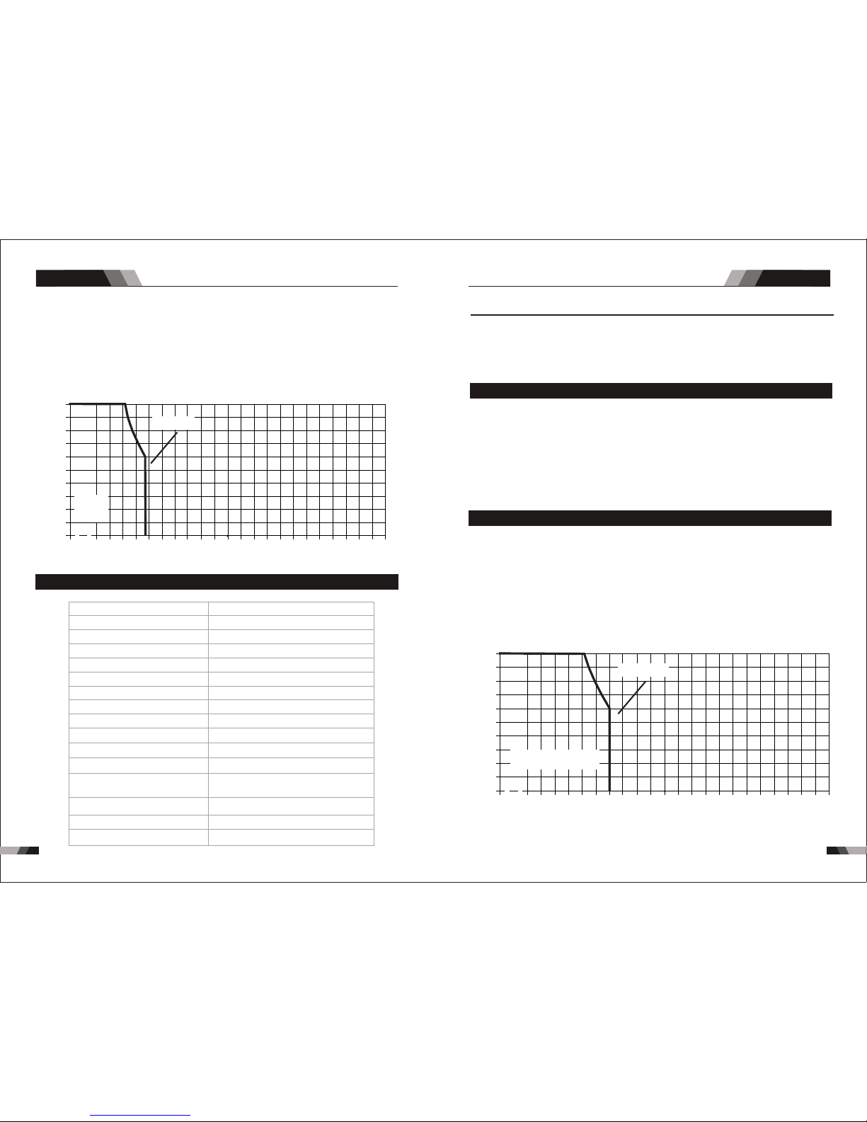
5554
Sum mary
CUTTING SERIES EQUIPMENT
CUTTING SERIES EQUIPMENT
Duty Cyc le(PERC ENTAG E)
Welding Current (AMPS)
25
50
75
100 1 25 1 50 175
0
10
20
30
40
50
60
70
80
90
10 0
20 0 22 5 25 0 27 5 3000
Saf e
Ope ratin g
Reg ion
C71 C UT
1.10 Duty C ycle
The r ated d uty cy cle of a We ldin g Powe r Sour ce is a st atem ent of the time it may be
ope rate d at its r ated w eldi ng cur rent o utpu t with out ex ceed ing th e temp erat ure li mits o f the
ins ulat ion of t he com pone nt par ts. To expl ain th e 10 min ute du ty cyc le per iod th e foll owin g
exa mple i s used . Supp ose a We ldin g Power Source is des igne d to ope rate a t a 60% du ty
cyc le, 10 0 ampe res at 1 20 vol ts. This means that i t has be en des igne d and bu ilt to p rovi de
the r ated a mper age (1 00A) f or 6 min utes , i.e. a rc wel ding t ime, out of eve ry 10 mi nute
per iod (6 0% of 10 m inut es is 6 mi nute s). Du ring t he oth er 4 minutes of t he 10 mi nute p erio d
the W eldi ng Pow er Sou rce mu st idle and be al lowe d to coo l.
Duty Cyc le( PERCENTA GE)
Weldi ng Curr ent(A MPS)
25
50
75
100 1 25 15 0 175
0
10
20
30
40
50
60
70
80
90
10 0
20 0 225 2 50 275 3 000
C10 1 CUT
Saf e Opera ting Re gion
NOTE
Due t o varia tions t hat can o ccur in m anufa cture d produ cts, cl aimed p erfor mance , volta ges,
rat ings, a ll capa citie s, meas ureme nts, di mensi ons and w eight s quote d are app roxim ate
onl y. Achi evable cap acit ies and rat ings i n use and ope rati on will dep end up on correc t
ins talla tion, u se, app licat ions, maint enanc e and ser vice
1.9 Packa ged Ite ms
◆Pla sma Torch 6 m PT10 0
◆300 A ear th clam p with 3M c able
◆3M Po wer cab le
◆Ope ratin g Manua l
C101
1.8 Specificat ions C1 01
H54 5mmxW 250mm xD450 mm
20 - 10 0A
17A
21. 9A
22. 8kVA
Des cript ion
Wei ght
Pow er Sour ce Dime nsion s
Coo ling
Wel der Typ e
Eur opean S tanda rds
Num ber of Ph ases
Nom inal Su pply Voltag e
Nom inal Su pply Fr equen cy
Wel ding C urrent Ran ge (CU T)
Sin gle Pha se Gene rator
Req uirem ent
Wel ding O utput , 40ºC, 1 0 min.
Ope n circu it volt age
Pro tecti on Clas s
Max imum In put Cur rent
Effective Input Current
VEC TOR DIG ITAL C10 1 CUT
27. 6 kg
Fan C ooled
Inv erter P ower So urce
EN 60 974-1 / I EC 6097 4-1
3
400 V +/- 15%
50/ 60Hz
100A @ 60%, 120V 77.5A @ 100%, 111V
300 V DC
IP2 3
The r ated d uty cycle of a We ldin g Powe r Sour ce is a st atem ent of th e time i t may be
ope rate d at its r ated w eldi ng cur rent o utpu t with out ex ceed ing th e temp erat ure li mits of the
ins ulat ion of t he com pone nt par ts. To expl ain th e 10 min ute du ty cyc le per iod th e foll owin g
exa mple i s used . Supp ose a Welding Power Sourc e is des igne d to ope rate a t a 60% du ty
cyc le, 70 a mper es at 10 8 volt s. This means t hat it h as bee n desi gned a nd bui lt to pr ovid e
the r ated a mper age (7 0A) fo r 6 minu tes, i .e. ar c weld ing time, out of ever y 10 min ute
per iod (6 0% of 10 m inut es is 6 mi nute s). Du ring t he other 4 minu tes of t he 10 mi nute p erio d
the W eldi ng Pow er Sou rce must idle and be al lowe d to coo l.
Sum mary
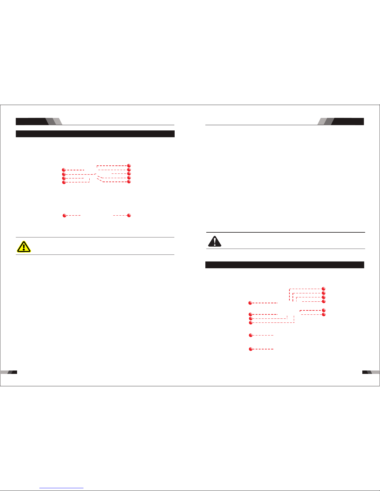
5756
Ope ratio n
CUTTING SERIES EQUIPMENT
CUTTING SERIES EQUIPMENT
2.2 Layout For The P anel C7 1
1
11
12
10
9
8
5
7
6
4
3
2
7.Posi tiv e Con trol
8. Negat ive C ont roll
The p ositi ve cont rol is us ed to plu s curre nt .
The n egati ve cont rol is us ed to min us curr ent.
CA UTI ON
Loo se weld ing t ermi nal co nne ctio ns can c aus e
ove rheat ing and r esu lt in th e male p lug b eing
fus ed in the b ayo net te rmin al.
10. Posi tiv e Welding O utp ut Term ina l
11.Plas ma Tor ch Connec tor
The p ositive cut ting t ermi nal is us ed to co nnect the cut ting o utput of the po wer source
to th e appro pria te wel ding access ory su ch as earth cla mp. It i s essen tial , howe ver, tha t
the m ale plu g is ins erte d and tur ned se cure ly to ach ieve a s ound electr ical c onne ction.
Pla sma tor ch inse rt in to co nne ct wit h the ma chi ne. It ’s nec essa ry to be su re that t he
plu g is co rrec tly an d tig htly c onne cte d to mai ntai n the e lect rici ty an d gas su pply.
9.Baro met er
The b arome ter sho ws the pr esent a ir pres sure.
6. Ai r pressure Fau ty In dicator
Air p ressu re low al arm.
4. Therm al Ov erl oad Indic ato r Lig ht
Thi s weld ing pow er sour ce is pro tecte d by a self r esett ing the rmost at. The i ndic ator wi ll
illumi nat e if the d uty c ycle o f the p ower s ourc e has be en ex ceed ed. S houl d the th erma l
ov erl oad indic ator i llu min ate t he output o f the po wer s our ce wi ll be d isa ble d. Once the
po wer s our ce cools down th is lig ht wi ll go O FF an d the o ver t emp era tur e con diti on wil l
au tomatic all y res et. N ote th at the m ain s pow er sw itch s houl d rem ain i n the o n posi tion
su ch that the f an con tin ues t o oper ate th us al low ing th e unit t o coo l suff icie ntl y. Do not
swi tch the u nit off s houl d a therm al over load co nditi on be pre sent.
2.1 Layout For The P anel C4 1
DO NO T TOUCH t he ele ctrod e wire wh ile i t is
bei ng fed th rou gh the s yste m. Th e elec trod e
wir e will be a t wel ding v olta ge po tent ial.
1. Digit al Di spl ay
2. Power I ndi cat or
3. Wo rk In dic ator
5. Plasm a Torc h Fauty Ind ica tor
The d igita l meter i s used to d ispla y the pre -set (p revie w) ampe rage fo r cutti ng and th e
act ual c utti ng cur rent.
The gr een po wer ind icat or will b e illum inat ed when t he welder is tu rned ON a nd indi cate s
the pr esen ce of pow er.
Tur n on the s witc h of the cu tting g un, gen erate t he volt age, th e lam p on.
WAR NIN G
2
7
10
8
11
1
3
9
4
5
6
Ope ratio n
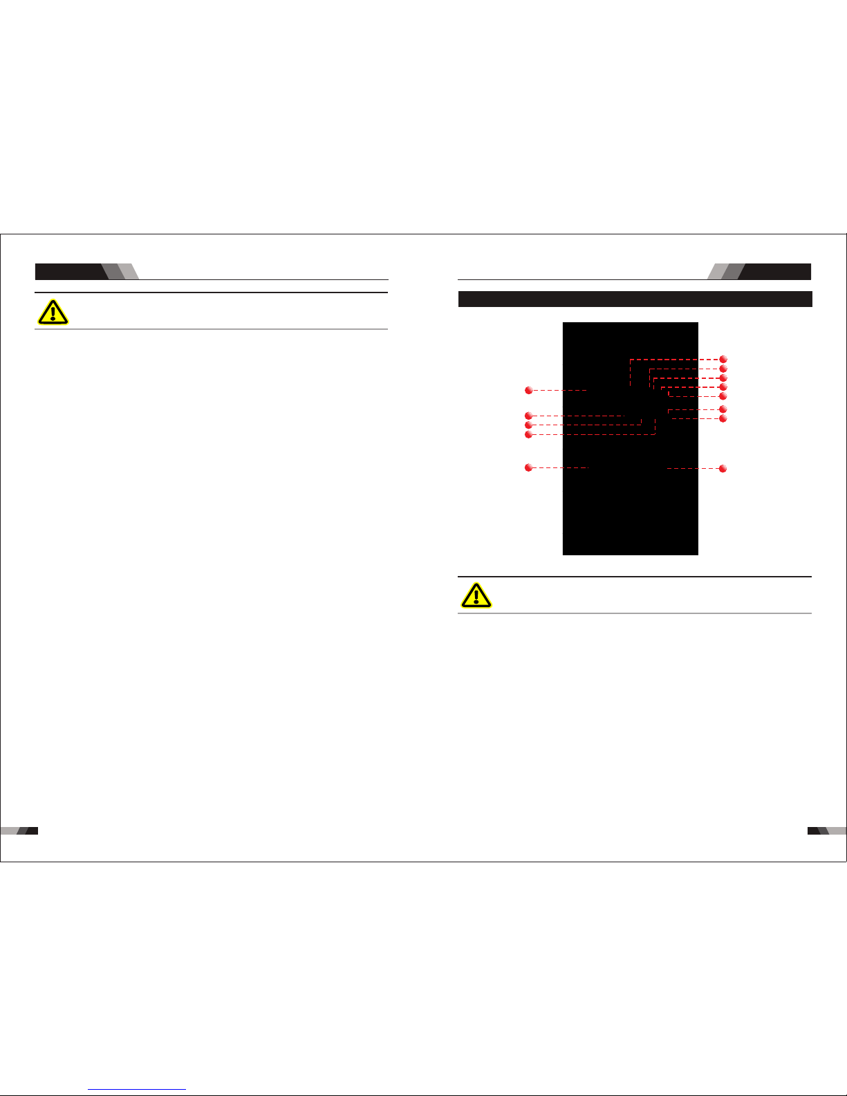
5958
Ope ratio n
CUTTING SERIES EQUIPMENT
CUTTING SERIES EQUIPMENT
2.3 Layout For The P anel C1 01
1
12
13
11
10
9
6
8
7
4
5
3
2
WAR NIN G
DO NO T TOUCH t he ele ctrod e wire wh ile i t is
bei ng fed th rou gh the s yste m. Th e elec trod e
wir e will be a t wel ding v olta ge po tent ial.
1.Baro met er
2. Digit al Di spl ay
3. Power I ndi cat or
The b arome ter sho ws the pr esent a ir pres sure.
The d igit al mete r is used t o displ ay the pr e-set ( pre view ) ampe rage fo r cutti ng and th e
act ual c utti ng cur rent.
The g ree n powe r indi cator w ill be il lumin ated wh en the we lder is t urned O N and in
dic ate s the pr esen ce of p ower.
4. Therm al Ov erl oad Indic ato r Lig ht
Thi s weld ing pow er sour ce is pro tecte d by a self r esett ing the rmost at. The i ndic ator wi ll
illumi nat e if the d uty c ycle o f the p ower s ourc e has be en ex ceed ed. S houl d the th erma l
ov erl oad indic ator i llu min ate t he output o f the po wer s our ce wi ll be d isa bled. Once the
po wer s our ce cools down th is lig ht wi ll go O FF an d the o ver t emp era tur e con diti on wil l
au tomatic all y res et. N ote th at the m ain s pow er sw itch s houl d rem ain i n the o n posi tion
su ch that the f an con tin ues t o oper ate th us al low ing th e unit t o coo l suff icie ntl y. Do not
swi tch the u nit off s houl d a therm al over load co nditi on be pre sent.
8. Cut fun cti on Se lect Butt on
9. Negat ive C ont rol
10. Posi tiv e Con trol
11. Posit ive W elding Ou tpu t Termi nal
Pre ss and re lease t his but ton to ch ange th e selec ted cut ting fu nctio ns mode .
The p ositi ve cont rol is us ed to plu s curre nt.
The p ositi ve cutt ing te rmina l is used t o conne ct the cu ttin g outpu t of the po wer sou rce
to th e appro priate weld ing acc essor y such as earth clamp. I t is esse ntial , howev er, that
the m ale plu g is inse rted an d turned secu rely to a chiev e a sound e lectrical c onnec tion .
12. Plas ma Tor ch Connec tor
7. Norma l Cut I ndi cator
Pre ss and re lease b utto n from8 t o chang e the sel ecte d cutti ng fun ction s mode , light o n ,
the fu ncti on is sel ecte d.
1. Digit al Di spl ay
2. Power I ndi cat or
The d igita l meter i s used to d ispla y the pre -set (p revie w) ampe rage fo r cutti ng an d the
act ual c utti ng cur rent.
The green po wer indicat or will be illu minated whe n the wel der is turned O N and ind icat es
the p resen ce of po wer.
4. Ai r Pressure/ Cu tti ng Torc h Fau ty In dicator
5. Wo rk In dic ator
Cut ting to rch imp roper i nstal latio n and air p ressu re low al arm.
Tur n on the s witc h of the cu ttign g un,ge nerat e the vol tage, t he lamp o n.
6. Grid Cu t Ind ica tor
Pre ss and re leas e button from 8 t o chang e the se lected cutt ing fu nctions mod e, lig ht on ,
the f uncti on is se lected.
3. Therm al Ov erl oad Indic ato r Lig ht
Thi s weld ing pow er sour ce is pro tecte d by a self r esett ing the rmost at. The i ndic ator wi ll
illumi nat e if the d uty c ycle o f the p ower s ourc e has be en ex ceed ed. S houl d the th erma l
ov erl oad indic ator i llu min ate t he output o f the po wer s our ce wi ll be d isa bled. Once the
po wer s our ce cools down th is lig ht wi ll go O FF an d the o ver t emp era tur e con diti on wil l
au tomatic all y res et. N ote th at the m ain s pow er sw itch s houl d rem ain i n the o n posi tion
su ch that the f an con tin ues t o oper ate th us al low ing th e unit t o coo l suff icie ntl y. Do not
swi tch the u nit off s houl d a therm al over load co nditi on be pre sent.
WAR NIN G
DO NO T TOUCH t he ele ctrod e wire wh ile i t is
bei ng fed th rou gh the s yste m. Th e elec trod e
wir e will be a t wel ding v olta ge po tent ial.
Ope ratio n
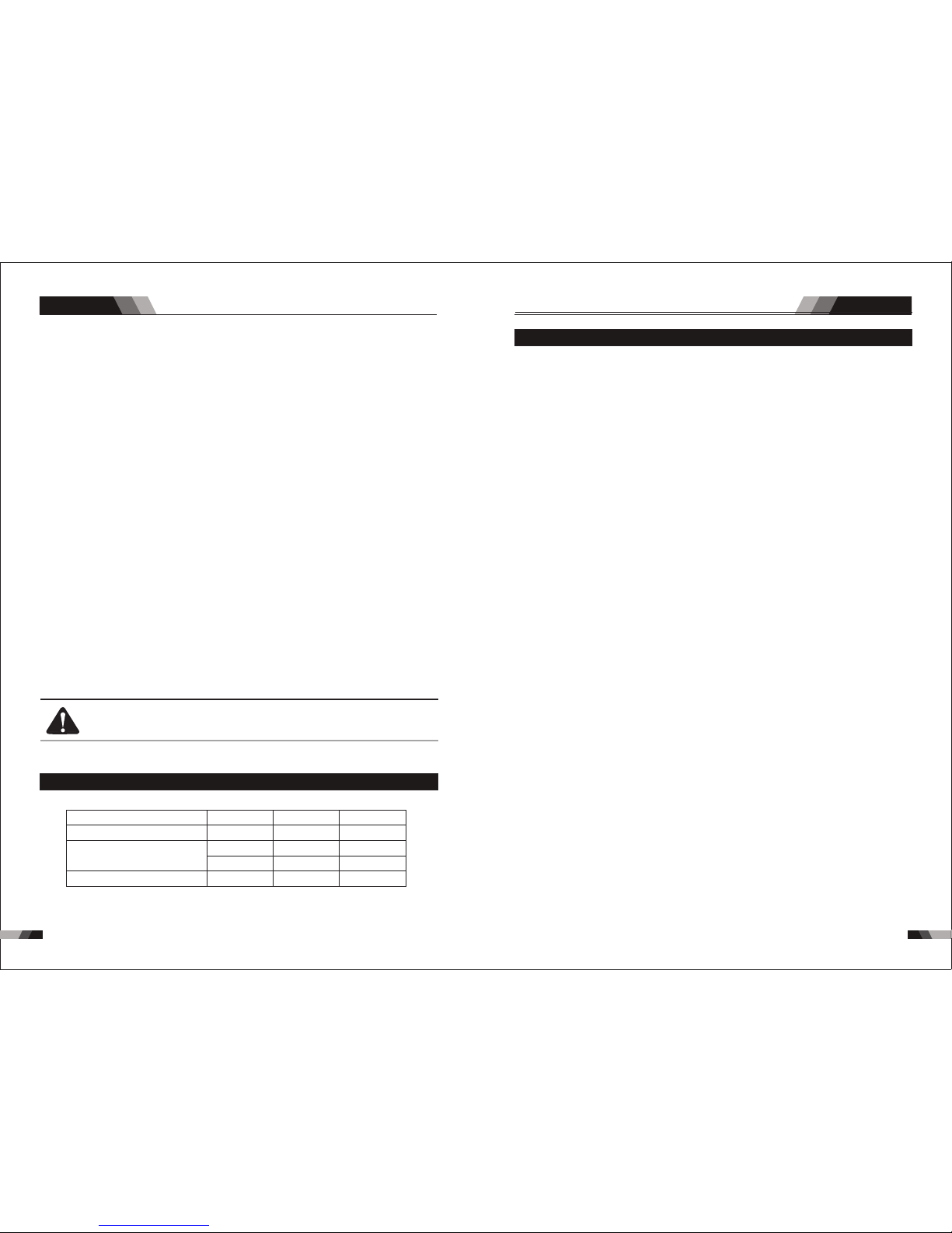
6160
Ope ratio n O perat ion
CUTTING SERIES EQUIPMENT
CUTTING SERIES EQUIPMENT
2.5 Installati on Inst ructions
In or der fo r the un it to fu ncti on correc tly, it mu st be in stal led pr operly. Fol low th e proc edure
giv en bel ow for c orrect instal lati on:
1. R ead th e safe ty rules give n in thi s manu al car eful ly.
2. C heck o n rece ivin g the uni t that t here a re no de fect ive pa rts or parts da mage d duri ng
tra nspo rtat ion.
3. A ttac h air re gula tor as sh ow in pi ctur e Ai r Regulator Insta llat ion on ly for C 71.
4. S et you r unit up in an are a whic h is ade quat ely ve ntil ated a nd make sure th at the a ir
ven ts are n ot obs truc ted.
5. C onne ct the p ower supply cable t o a sock et loc ated a s near a s possible to t he wor k area ,
so th at the u nit ca n be switched off qui ckly i n case o f emergency.
6. You r machine has a 1 6 amp pl ug fit ted, b efor e use check tha t the gr een/ yell ow ear th is
con nect ed to th e eart h pin socket of fitte d plug .
7. M ake su re that the mai ns sup ply sw itch a nd any f uses h ave a val ue whi ch ± 15% t he
max imum c urre nt abs orbe d by the unit. All f uses s houl d be the s low- blow t ype.
8. An y exte nsio ns of pow er sup ply ca ble sh ould h ave th e same c ross -sec tion as the pow er
sup ply ca ble. The exte nsio n lead s, how ever, s houl d only b e used when abs olut ely
nec essa ry. It is im port ant to n ote th at any e xten sion o f mains cable s or tor ch cab les wi ll
pos sibl y affe ct the cu ttin g perf orma nce of t his cu ttin g equi pmen t, due t o the fac t that t he
res ista nce of t he cab le wil l reduce voltage in put, w hich i s dete rmin ed by th e leng th of the
cab le. Th e supplied le ngth o f main c able s and to rch ca bles i s recommended.
9. F aste n the ea rth clamp to th e piec e to be cu t, If th e surface of th e piec e to be cu t is
pai nted , rust y or cov ered w ith insulating ma teri al, cl ean th e surf ace so t hat
sat isfa ctor y cont act be twee n the pi ece and the ear th cla mp can b e obta ined .
10. Make s ure th at the t orch h as been assembled with th e corr ect co mpon ents a nd tha t the
cut ting t ip is su itab le for the cutt ing cu rren t.
11. Co nnec t air to r egul ator a nd adj ust re gula tor to delive r 5-6 ba r 90lt r/mi n
12. Swit ch the u nit on u sing t he mai n switch loca ted on t he bac k side .
13. pres s the cu ttin g torc h to ach ieve a pilot fr om the c oppe r tip, w hen th is pil ot is up to t he
wor k piec e , cutt ing op erat ion begins.
14. Onc e cutt ing is o ver, rel ease th e torch b utton t o put out t he arc. A per iod of po st-fl ow
tim e 45 to 7 5 seco nds (r equ ired f or tor ch co olin g) wil l follo w. Do not di sconn ect air
unt il th is coo ling p eriod h as been c omple ted. Fa ilure t o do this w ill res ult in to rch hea d
dam age.
5. Ai r Pressure/C utt ing Tor ch Fa uty I ndicato r
Cut ting Torc h impr oper in stall ation and ai r pres sure low al arm.
6. Wo rk In dic ator
Tur n on the s witc h of the cu ttign g un,ge nerat e the vol tage, t he lamp o n.
7. Grid Cu t Ind ica tor
8. Norma l Cut I ndi cator
Pre ss and release b utton f rom 8 to ch ange th e sele cted cu ttin g funct ions mo de, light on ,
the fu ncti on is sel ected.
Pre ss and re leas e butt on from 8 t o chan ge the se lect ed cut ting fu ncti ons mo de, lig ht on ,
the f unction is se lect ed.
9. Cut fun cti on Se lect Butt on
Pre ss and re lease t his but ton to ch ange th e selec ted cut ting fu nctio ns mode .
11. Negat ive C ont rol
10. Posi tiv e Con trol
The n egati ve cont rol is us ed to min us curr ent.
The p ositi ve cont rol is us ed to plu s curre nt.
12. Posi tiv e Welding O utp ut Term ina l
The p ositi ve cutt ing termina l is used t o conne ct the cu tting o utput of the pow er source
to th e appro priat e welding acc essor y such as e arth cl amp. It i s essen tial , howev er, that
the m ale plu g is inse rted an d turne d securely to achiev e a sound e lectr ical co nnec tion.
13. Plas ma Tor ch Connec tor
CA UTI ON
Loo se weld ing t ermi nal co nne ctio ns can c aus e
ove rheat ing and r esu lt in th e male p lug b eing
fus ed in the b ayo net te rmin al.
2.4 Steel C uttin g Capab ility (Thickness to sca le.)
Cap acity
Qua lity Cu tting T hick ness
(50 0mm/m in)
Max imum Cu tting C apaci ty
Thi cknes s Thickne ss Thi cknes s
Cut ting Cut ting Cut ting
10m m 20m m 30mm
20m m 30m m 50mm
C41 C71 C101
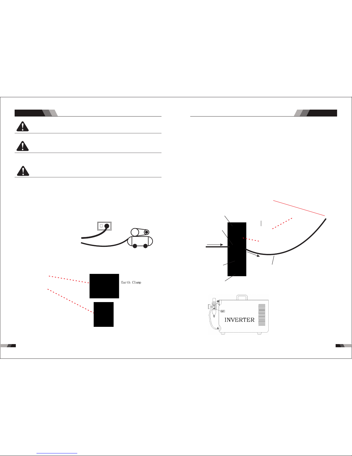
6362
Ope ratio n
CUTTING SERIES EQUIPMENT
Air r egula tor ins tal lati on and o per atio n
1. Fi rmly ti ght and s eal t he cop per ai r hol e at IN an d OUT te rmin al by h igh
pre ssure r ubber t ube .
2.T ight a nd sea l the met er with m eter fa ce rubb er tube .
3.F ix the co nnect ing she lf with s crew as t he regu lator p ositi on.
4.G et down t he plas tic scr ew and fi x the reg ulato r on the sh elf.
5.T urn on t he air v alve, t urn up th e press ure adj ustin g knob, t urn the p ressu re
vol ume (me ter ins ide sho ws kg), a nd then p ut down t he kn ob.( + mean s incre asing
pre ssure , -- mean s decre asing p ressu re.)
6.S cale of t he mete r is as fol low. The v olum e in the pi cture i s 6 kg.
7. If t he wate r in theg as fi lter ing bo ttle is t oo mu ch, pl ease t urn on th e water v alve to
let t he wate r go out.
Con necti ng shel f
Pre ssure a djust ing kno b
Com press ed air
Pre ssure m eter
Air f iltin g bottl e
Air p ipe
Air o ut
Air i n
Dra inage i nterf ace
CUTTING SERIES EQUIPMENT
Ope ratio n
CA UTI ON
CA UTI ON
CA UTI ON
Do n ot po int the t orc h jet a t for eig n bod ies .
Av oid un ne ce ss ar y li ght in g of the pi lo t ar c to pre ve nt e xce ss iv e
co ns um pt io n of the el ec tr od ea nd n oz zl e.
Cut ting to rch
power su ppl y
Du rin g cut tin g the s peed of th e tor ch mo vem ent s houl d be in a cco rda nce w ith t he
th ick nes s of th e pie ce to b e cut . Exc ess ive s peed c ause s a ret urn o f inc and esc ent
to war ds th e tor ch wh ich shorten s the l ife o f the parts of t he to rch m ost su bjec t to
Air c ompre ssor
wear a nd tear. The metal fouling on the nozzle should be rem oved as soon as possi ble.
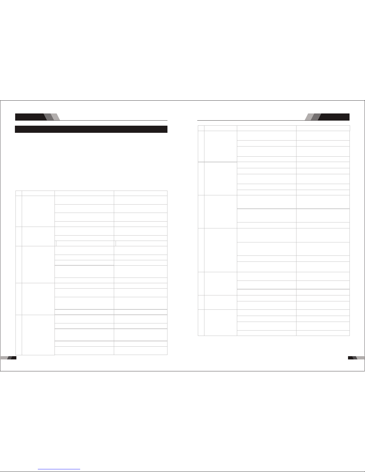
6564
Tro ubles hooti ngTro ubles hooti ng
CUTTING SERIES EQUIPMENT
CUTTING SERIES EQUIPMENT
3.1 Troubleshoo ting
◆Bef ore arc w eldin g machi nes are d ispat ched fr om the fa ctory, t hey ha ve alre ady bee n
deb ugged a ccura tely. So f orbi d anyon e who is no t autho rized b y us to do an y chang e to
the e quipm ent!
◆Mai ntena nce cou rse mus t be oper ated ca reful ly. If any w ire be comes f lexib le or is
mis place d, it may be pote ntial d anger t o user!
◆Onl y profe ssion al main tenan ce pers onal wh o is auth orize d by us cou ld over haul th e
mac hine!
◆Gua rante e to shut o ff the ar c weld ing mac hine’ s power bef ore tu rn on the out line o f
the e quipm ent!
◆If th ere is an y probl em and ha s no the au thori zed pro fessi onal ma inten ance pe rsona l,
ple ase con tact lo cal age nt or the b ranch c ompan y!
If th ere a re som e simp le trou bles of W SME-s eri es wel ding m achin e, you ca n consu lt
the f ollow ing ove rhaul ing cha rt:
Nr.
Nr.
1
5
6
7
8
9
10
11
12
2
3
4
Troubles
Troubles
Solution
Solution
Fan is broken and the control board
broken
Gas pipe not connected or pressure
is too low
The input or output of the air flow
around the machine is blocked
Faulty compone nts in the machine
Consult the dealer or manufacturer
to repair
Change fan and control board
Fan blocked
Over-heat appe ar
Correct the condition
Check and correct it
let meachine cool down 5 minutes
and make sure the duty cycle is
not exceeded
Input voltage is not correct
Input voltage is not correct
Input voltage is not correct
Torch parts broken
Inspect torch parts and replace
if necessary
Gas pressure too low or too high
Gas pressure too low or too high
The gas distributor is uninstalled
Torch parts are worn
The cutting torch is broken
Power supply is overheated
Torch consumbles are worn
Air regulator is broken
Incorrect sett ing of cutting curren t
Cutting curren t is too low
Increase the cutting current
Reduce cutting speed
The movement of torch is too fast
Faulty compone nts in the machine
Faulty compone nts in the machine
Change or repair it
Check and replace
Change it
Consult the dealer or manufacturer
to repair
Check the gas connection, adjust the
proper setting
Consult the dealer or manufacturer
to repair
Check and adjust the cutting current
Consult the dealer or manufacturer
to repair
Excessive oil or moisture in torch
Do not directly start to cut before
cleaning the torch
Check the air pressure and air flow lack of air pressure
Check and adjust the gas setting
at least 65psi/4.5 bar
let meachine cool down 5 minutes
and make sure the duty cycle is
not exceeded
Check and change the torch parts
Consult the dealer or manufacturer
to repair
Install it
Machine is in trouble
The connection between cutting
torch and machine is not correct o
r the connection is poor
Check the torch leads are properly
connect to the machine
Earth clamp not correctly connect to
the work piece
Gas pressure too low , the torch/gas
indicator is on when torch switch is
pressed
Make sure the earth clamp has a
proper connection to a clean and
dry area of the workpiece
Adjust it to proper rate
Adjust it to proper rate
Consult the dealer or manufacturer
to repair
Faulty compone nts in the machine
Choose the proper voltage
Choose the proper voltage
Choose the proper voltage
Connect correc tly
Faulty compone nts in the machine
Change the power light
Change it
Change it
Connect correc tly
Repair or change it
Change it
Change it
Install and screw properly
Check and change
Install and screw properly
Adjust the gas pressure to 65psi/
4.5 bar,the barometer indicate up
to 0.4Mpa or 60psi.
Clean it and change the control
board
Change capacit or and control
board
There is something in the fan and
the control board broken
The start capacitor of fan damaged
and the control board broken
The power light damaged or
connectio n is not good
The tip or electrode is unfitted
installat ion
The power cable connected not
good
The light of the power indicator is
broken and the problems mentioned
in Nr. 2
Change the light of the power
indicator or refer to the solution
in Nr. 2
The input lines not corretly connected
The power board is broken
The power cable is broken
The power board is broken
The shield cup is unfitted installation
Cutting torch is broken or mistake
Gas pressure too low
Power on switch is damaged
Tur n on the
pow er sour ce,
pow er indi cator
is li t, fan an d air
con trol va lve are
not w orkin g
The o ver-h eat
ala rm is on af ter
a few m inute s
cut ting
Whe n torch i s
pre ssed th e torch
fai led to ig nite th e
arc
When torch is
pressed the to rch
is difficult to ignite
After triggering
the to rch ,the pilot
arc ca nnot cha nge
to the cutting pilot
Arc shuts off during
operation and it will
not restart when
torch is triggered
The power indicator
is on ,fan is working
but no gas flow , gas
indicator is on
low cutting output
Torch can cut but
the quality is poor
Tur n on the
pow er sour ce,
fan i s worki ng,
pow er indi cator
is no t lit
Turn on the
power sou rce,
fan is not worki ng,
power ind icator is
not lit
Turn on the power
source, Torch/Gas
indicator is on
Reasons
Reasons
Display panel is broken

6766
DC PULSE SERIES EQUIPMENT
CHAPTER 4
DC PULSE SERIES EQUIPMENT
T-SER IES
1.1 Brief Introd uctio n
T231/ T331 wel ding mac hine adopts the lat est pulse width mod ulatio n (PWM) tec hnolo gy
and insulated gat e bipo lar transi stor (IGBT) power module, wh ich can change w ork fre quency
to m ediu m fre que ncy so a s to rep lac e the tr adit iona l hul kin g work fr equenc y transfo rme r
with the ca binet medi um frequen cy transformer. Th us, i ts charac ter ized w ith po rta ble, s mal l
si ze, li ght w eig ht, lo w cons umption a nd et c.
The p ara met ers o f T23 1/T33 1 on t he fron t panel all can b e adju sted c ontin uous ly and
steple ssly, such as start cu rrent, c rate r arc current , weld ing current , base c urrent, dut y rati o,
ups lope t ime, do wnsl ope ti me, pr e-g as, p ost- gas, p uls e fre que ncy, hot s tart , arc for ce and
len gth et c. When w eldi ng, it ta kes hi gh frequency an d high voltag e for ar c ignit ing to e nsure
the s ucce ss rati o of ign itin g arc.
T23 1/T33 1 Chara cteri stics :
◆MCU c ontro l syste m, resp onds im med iate ly to an y cha nges .
◆Hi gh fr equ enc y and hig h vol tag e fo r ar c ig nit ing t o ens ure t he su cce ss r ati o of
ig nit ing a rc.
◆ Wit h spe cial m eans , eve n if arc -bre ak oc curs t he HF wi ll ke ep the a rc sta ble .
◆Ped al cont rol the w eld ing cu rren t.
◆p ur po se s: DC i nv er te r T IG , E xc el le nt pe rf or ma nc e o n c ar bo n s te el ,
s ta in le ss s te el , t it an iu m et c.
According to choo sing t he fr ont pan el fu nct ions, t he fo llo wing fo ur we ldi ng ways
ca n be re alized.
DC M MA
DC T IG
DC P uls e TIG
1. Fo r DC MMA, p olari ty conn ectio n can be ch osen ac cordi ng to dif fere nt elec trode s;
2. F or DC T IG, D CEP is us ed no rmall y (w ork piece c onn ect ed to p osi tiv e pol arity, w hil e
t orch c onnec ted to n eg at ive po larit y). Thi s co nn ect ion ha s ma ny c har act ers , su ch
a s s ta bl e wel di ng a rc , l ow t un gs te n po le l os s, m ore we ld in g cu rr en t, n arro w an d
dee p weld;
3. DC P ulsed T IG has t he foll owing c harac ters:
1) Pu lse hea ting. M etal in M olten p ool has s hort ti me on hig h tempe ratur e statu s
and f ree zes qu ickl y, whi ch can re duce th e possi bility to pr oduc e hot cr ack of th e
mat eri als wi th the rmal se nsiti vity .
Sum mary
DC PULSE SERIES EQUIPMENT
◆In DC T IG with out H Fope rtat ion , If the t ungs ten e lect rode t ouc hes th e work pie ce
whe n weldi ng, t he cur rent w ill d rop to s hort -ci rcui t curr ent t o prot ect tu ngs ten.
◆
occ oure d, the a larm la mp on th e fron t panel will be o n and th e outpu t curr ent wi ll
be cu t off. It can sel f-pr otec t and pr olong the usi ng lif e.
In tel li gen t pr ote cti on: o ver -cu rr ent , ov er- hea t, wh en t he m ent ion ed pr obl ems
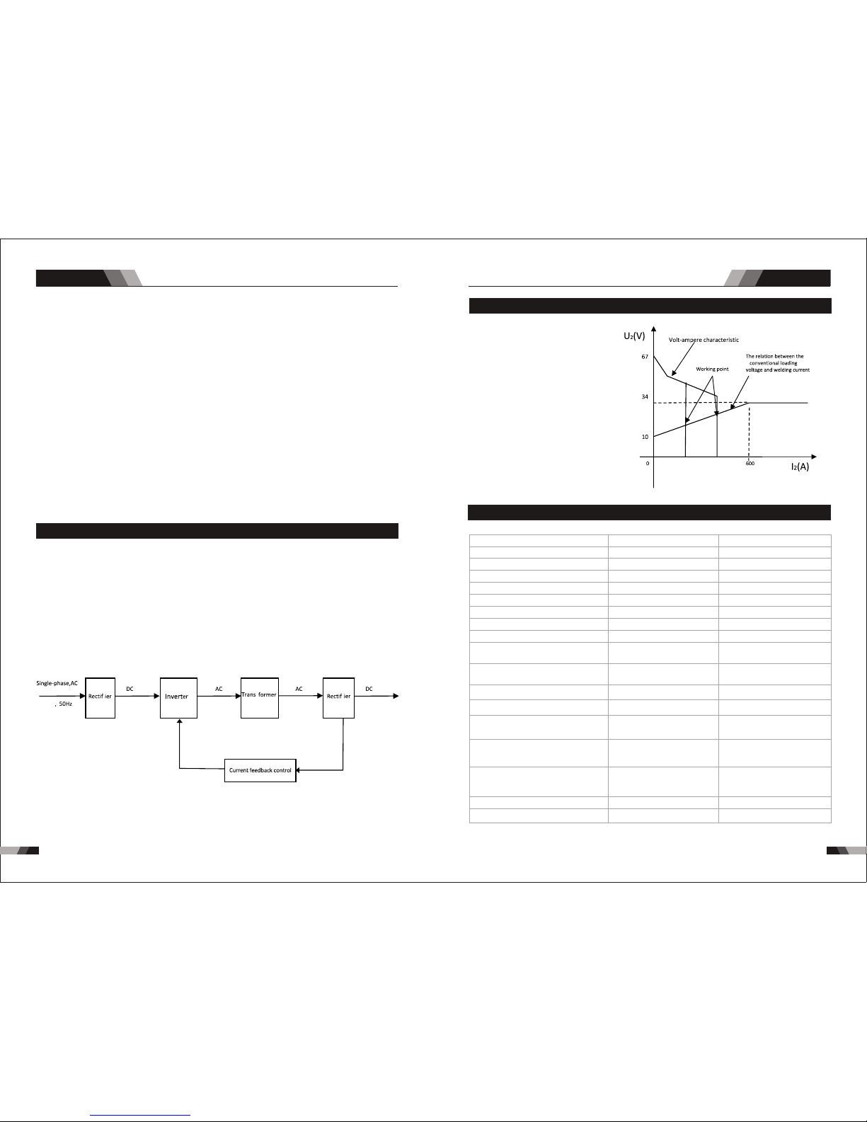
6968
Sum mary
DC PULSE SERIES EQUIPMENT
2) Th e wor kpiece ge ts li ttle h eat . Ar c ener gy is fo cuse d. Be s uitable f or th in she et
and s uper th in shee t weldi ng.
3) E xact ly contro l heat inpu t and t he siz e of th e molt en po ol. Th e dept h of pen etra tio n
is ev en. B e suit able f or weld ing by on e side an d formi ng by two s ides an d all pos ition
wel ding fo r pipe.
4) Hi gh freq uency a rc can ma ke meta l for mic rolit er fabr ic, eli minat e blowh ole and
imp rove th e mec hani cal pe rform ance of t he join t.
5) Hi gh freq uency a rc is sui table f or high w eldin g speed t o impro ve the pr oduct ivity.
T23 1/T3 31 –s erie s weld ing mac hines i s suita ble for a ll posi tions w eldin g for
var ious pl ates ma de of sta inles s steel , carbo n steel , alloy ed stee l, tita nium, m agn esiu m,
cup rum, et c, Whic h is also a pplie d to pipe i nstal lment , mould m end, pe troch emica l,
arc hitec ture, d ecora tion, c ar repa ir, bicy cle, ha ndicr aft and c ommon m anufa cture .
MMA ----- --Man ual Met al Arc Wel ding
PWM ----- --Pul se-Wi dth Mod ulati on
IGB T----- ---In sulat ion Gat e Bip olar Tr ansi stor
TIG ---- ----- -Tung sten I nser t Gas Wel ding
1.2 Wor king Pr inciple
230V
1.3 Volt - Ampere Cha racte ristic
T231 /T331 we lding ma chin e has an
exce llent vo lt-amp ere characteristic,
whose graph is shown as the following
fi gur e. T he relat ion be tw ee n the
conventional rated loading voltage U
2
and the conventional welding current
I is as fo llows :
2
Whe n I ≤600A , U =10 +0.04 I (V) ;
2 2 2
Whe n I >60 0A,U =34 (V).
2 2
1.4 Specificat ions T2 31/T331
IP2 3
Des cript ion
Wei ght
Pow er Sour ce Dime nsion s
Coo ling
Wel der Type
Eur opean S tanda rds
Num ber of Ph ases
Nom inal Su pply Vol tage
Nom inal Su pply Fr equen cy
Wel ding Cu rrent R ange
(DC S TICK Mo de)
Wel ding Cu rrent R ange
(DC T IG Mode )
Sin gle Pha se Gene rator
Req uirem ent
STI CK (MMA )
Wel ding Ou tput, 4 0ºC, 10 m in.
TIG ( GTAW)
Wel ding Ou tput, 4 0ºC, 10 m in.
Ope n circu it volt age
Pro tecti on Clas s
Max imum In put Cur rent
Effective Input Current
T23 1
10. 9 kg
H39 5mmxW 180mm xD370 mm
Fan C ooled
Inv erter P ower So urce
EN 60 974-1 / I EC 6097 4-1
1
230 V +/- 15%
50/ 60Hz
5 - 200 A
5 - 200 A
32. 3A
41. 7A
14. 4kVA
200 A @ 60% , 28V
110A @ 10 0%, 24. 4V
200 A @ 60% ,18V
155 A @ 100 %, 16.2 V
66V D C
IP2 3
19. 6 kg
Fan C ooled
Inv erter P ower So urce
EN 60 974-1 / I EC 6097 4-1
3
400 V +/- 15%
50/ 60Hz
30 - 25 0A
10 - 30 0A
8.6 A
13. 7A
14. 2KVA
250 A @ 40% , 30V
158 A @ 100 %, 26.3 V
300 A @40 %, 22V
190 A @ 100 %, 17.6 V
66V D C
H51 5mmxW 220mm xD380 mm
T33 1
Sum mary
DC PULSE SERIES EQUIPMENT
The working p rinc ipl e of T2 31/T331 weld ing ma chi nes i s sho wn as t he fo llo wing
fi gure. Single -pha se 23 0V wo rk fr equ ency A C is re cti fied into DC(a bout 3 12 V) , the n
re ctifyin g by med ium f req uen cy re cti fier (fas t reco ver y dio des ),t hen is outputt ed DC .T he
Me anwhile , the we ldi ng cu rre nt pa ram eter can be adjuste d cont inu ous ly an d ste plessly
to m eet t he re qui rements o f weld ing c raf t.
is con verte d to medi um frequency AC (a bout 20- 40KHz) by inve rter de vice (IGBT modu le),
af ter r edu cin g vol tage by me diu m tra nsf orm er (t he ma in tr ans for mer ) and r ect ify ing
ci rcu it ad opt s cur ren t fee dba ck co ntr ol t ech nol ogy to in sur e cur ren t ou tpu t sta bly.
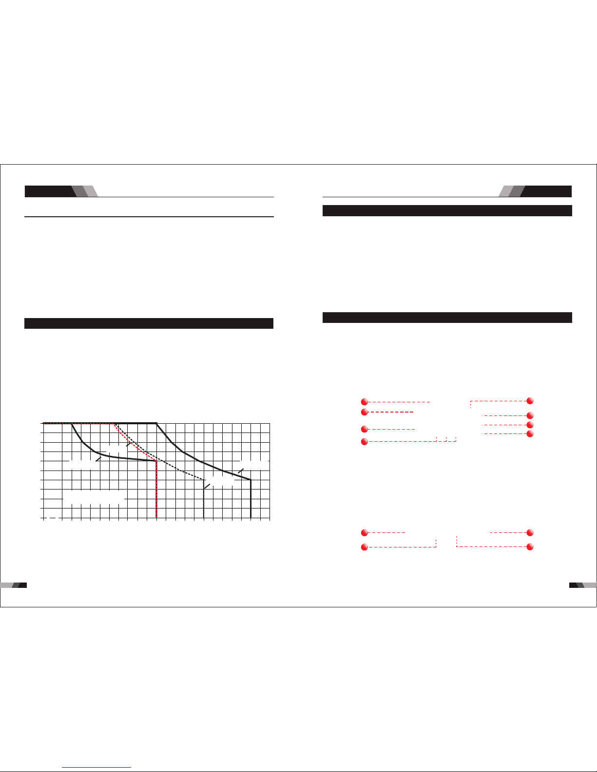
717 0
Sum mary
DC PULSE SERIES EQUIPMENT
Not e 1: The Ef fect ive In put Cur rent sh ould be u sed for t he dete rmina tion of c able si ze &
sup ply r equi reme nts .
Not e 2: Gene rator R equir ement s at the Ma ximum O utput D uty Cyc le.
Not e 3: Moto r start f use s or the rmal c ircui t break ers are r ecomm ended f or this a ppl icat ion.
Che ck lo cal re quir ement s for you r sit uati on in th is rega rd.
Due t o varia tions t hat can o ccur in m anufa cture d produ cts, cl aimed p erfor mance , volta ges,
rat ings, a ll capa citie s, meas ureme nts, di mensi ons and w eight s quote d are app roxim ate
onl y. Achieva ble ca pacitie s and ra tings in us e and op eration w ill de pend upon c orre ct
ins talla tion, u se, app licat ions, m ainte nance a nd serv ice.
1.5 Duty Cy cle
The r ated d uty cyc le of a Wel ding P ower So urce, i s a state ment of t he ti me it ma y be
ope rated a t its rat ed weld ing cur rent ou tput wi thout e xceed ing the t emper ature l imits o f
th e in sulat ion of t he c omp one nt p ar ts. To ex pla in t he 1 0 mi nut e du ty c ycl e perio d th e
fo llo win g exa mpl e is u sed . Sup pos e a Wel din g Pow er S our ce i s des ign ed to ope rat e at
a 40 % dut y cyc le, 300 a mpe res a t 22 vo lts . Thi s mea ns th at it has b een des ign ed an d
buil t to p rov ide the rat ed am per age ( 300 A) f or 4 m inu tes , i. e. a rc w el din g ti me, out of
ev ery 10 mi nut e per iod ( 40% o f 10 m inu tes i s 4 mi nut es) . Dur ing t he o the r 6 mi nut es of
th e 10 m inu te peri od th e Wel din g Pow er So urc e mus t id le a nd b e al low ed to cool. T he
the rmal cu t out wil l opera te if the d uty cyc le is exc eeded .
Duty Cyc le( PERCENTA GE)
Weldi ng Curr ent(A MPS)
10 0 12 0 14 0 16 0 18 0 2 00 2 20
0
10
20
30
40
50
60
70
80
90
10 0
24 0 26 0 28 0 30 0 32 00
T33 1 TIG
T33 1 stick
T23 1 stick
T231 TIG
Saf e Opera ting Re gion
(TI G&STI CK)
2.1 Layout For The P anel T2 31/T331
◆3M Po wer cab le
◆200 Am p elect rode ho lder wi th 3M cab l .
◆200 Am p earth c lamp wi th 3M cab le
◆4M TI G Torch WP2 6
◆3M Ga s Hose
◆Ope ratin g Manua l
1.6 Packa ged Ite ms
T231
◆3M Po wer cab le
◆300 Am p elect rode ho lder wi th 3M cab le
◆300 Am p earth c lamp wi th 3M cab le
◆4M TI G Torch WP1 8
◆3M Ga s Hose
◆Ope ratin g Manua l
T331
3
2
4
10
12
1
7
8
9
11
5
6
Ope ratio n
DC PULSE SERIES EQUIPMENT
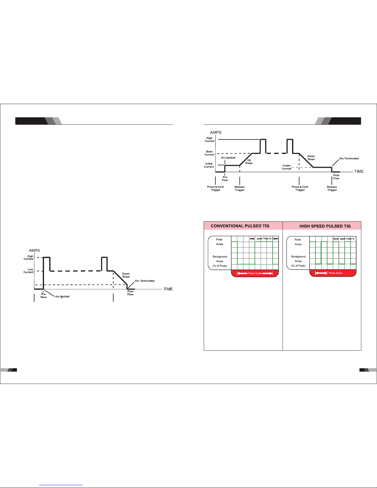
7372
Ope ratio n
Ope ratio n
DC PULSE SERIES EQUIPMENT
DC PULSE SERIES EQUIPMENT
No te: t hat w hen o per ating i n GTAW ( HF and LI FT TI G mo des), t he po wer sou rc e wi ll
rem ain act ivate d until t he sele cted do wn slop e time ha s elaps ed
Min imum
Cur rent
Pre ss & hold
Tri gger
Rel ease
Tri gger
1. Power O N Ind ica tor
The PO WER ON i ndicator il lumi nates when th e ON/OF F swit ch is in th e ON position a nd
the c orrec t mains v olt age is p rese nt.
Therma l Ove rlo ad Indica tor L igh t
Thi s weld ing pow er sour ce is pro tecte d by a self r esett ing the rmost at. The i ndic ator wi ll
illumi nat e if the d uty c ycle o f the p ower s ourc e has be en ex ceed ed. S houl d the th erma l
ov erl oad indic ator i llu min ate t he output o f the po wer s our ce wi ll be d isa ble d. Once the
po wer s our ce cools down th is lig ht wi ll go O FF an d the o ver t emp era tur e con diti on wil l
au tomatic all y res et. N ote th at the m ain s pow er sw itch s houl d rem ain i n the o n posi tion
su ch that the f an con tin ues t o oper ate th us al low ing th e unit t o coo l suff icie ntl y. Do not
swi tch the u nit off s houl d a therm al over load co nditi on be pre sent.
2. Proce ss Se lec tion Butt on
Th e pro ces s sel ect ion c ont rol i s use d to se lec t the d esi red w eld ing m ode . Two mo des
are a vaila ble, GTAW ( TIG ) and MM A (S tick ) mode s.
4. Pu lse B utton
Pre ss the PU LSE but ton t o togg le Pul se On and O FF.
Typi cally f rom 1 to 10 P PS. Pro vides a h eatin g
and c oolin g effec t on the w eld pud dle an d can
red uce dis torti on by low ering t he aver age
amp erage . Th is heat ing and c oolin g effec t also
pro duces a d istin ct ripp le patt ern in th e weld
bea d. The re lati onshi p betwe en pul se freq uency
and t ravel s peed de termi nes the d istan ce
bet ween th e rippl es. Slo w pulsi ng can al so be
coo rdina ted wit h fille r metal a dditi on and
inc rease o veral l contr ol of the w eld pud dle
In ex cess of 4 0 PPS, Pu lsed TI G beco mes mor e
aud ible th an visi ble-c ausin g incre ased pu ddle
agi tatio n for a bet ter as- welde d micro struc ture.
Pul sing th e weld cu rrent a t high sp eeds- betwe en
a hig h Peak an d a low Bac kgrou nd ampe ragecan a lso con stric t and foc us the ar c.Thi s resul ts
in ma ximum a rc stab ility, i ncre ased pe netra tion
and i ncrea sed tra vel spe eds(C ommon R ange:
100 -500 PP S).
The Ar c-Sha rpeni ng effe cts of h igh spe ed
pul sing ar e expan ded to ne w dimen sions . The
abi lity to p ulse at 5 ,000P PS furt her enh ances
arc s tabil ity and c oncen trati on pote ntial -whic h
is ex tre mel y benef icial t o autom ation w here
max imum tr avel ts peeds a re requ ired.
4T L atc h mo de th is mo de of w eld ing i s mai nly u sed f or long w eld ing r uns t o reduc e
op era tor fat igu e. In thi s mod e the o per ator can p res s and r ele ase the t orc h tri gge r and
th e out put w ill r emai n act ive . To dea cti vate the p owe r sou rce , the tri gge r switc h mus t
ag ain b e pre sse d and rel eas ed, thu s eli mina tin g the n eed f or th e op era tor t o hol d the
to rch t rig ger.
3. Trigge r Mod e Con trol Butt on (H F TIG a nd LIFT TIG M ode o nly)
The t rig ger mo de con trol is u sed to sw itch th e funct ion alit y of the t orch tr igg er bet ween
2T an d 4T.
ou tput t o be ac tive .
Press an d hol d the to rch t rigg er to a ctiv ate th e powe r sou rce (w eld) . Rele ase t he tor ch
trigge r swi tch to c eas e weld ing .
2T N orm al M ode In th is mo de, t he to rch t rig ger mus t rem ain p res sed for the wel din g

75
74
8. JOB and S AVE
9. Negat ive W elding Ter minal
Ne gat ive Wel din g Term inal. W eld ing c urren t fl ows f rom t he P owe r Sou rce via h eav y
duty bay one t ty pe t er min als . It i s es sen tia l, h ow eve r, th at t he m al e pl ug i s in ser ted
and t urn ed sec urel y to achi eve a sou nd elec trica l conne ction .
Ant i-sti ck prev ents th e elect rode fr om an neal ing.
If t he el ect rod e sti cks i n sp ite of th e arc ror ce d evi ce , the
mac hi ne au to ma ti ca ll y sw it ch es o ve r t o th e mi ni mum
cu rrent wi th in a bou t 1 se co nd t o pr event th e el ect ro de
f ro m o ve rh ea ti ng . I n or de r to ea si ly s ep ar at e th e
e le ct ro de a nd el ec tr od e h ol de r t o pr ot ec t th e wel de r.
Anti stick
Anti stick
U
I
5. Negat ive C ont rol
The N egat ive but ton is us ed to min us sele cted in P rogra mming s equen ce..
Positi ve Co ntr ol
The P ositi ve butt on is use d to plus s elect ed in Pro gramm ing seq uence ..
7. Hot Sta rt
Arc force Correc tio n
Hot S tart Fu nctio n relia bly ign ites th e elect rode
and m elts pe rfect ly to ens ure the b est qua lity
eve n at the st art of th e sea m. thi s solu tion ma kes
lac k of fusi on and co ld weld s a thing o f the pas t
and s ignif icant ly redu ces wel d reinf orcem ent.
Adj ust the h ot star t curre nt here a nd the ti me he re.
Dur ing the w eldin g proce ss, arc force p reven ts
t he el ec tr od e s ti ck in g in th e w el d p oo l w it h
inc rease s in curr ent. th is make s it easi er to wel d
lar ge-dr op mel ting el ectro de typ es at low curren t
str ength s with a sh ort arc i n parti cular.
I
t
Ope ratio n
Ope ratio n
DC PULSE SERIES EQUIPMENT
DC PULSE SERIES EQUIPMENT
CAUTION
Lo ose wel ding te rmi nal c onn ect ion s can cau se o ver heati ng a nd re sul t in t he ma le pl ug
be ing fus ed i n the ter min al.
2.2 Control Pane l
10. Posi tiv e Welding Te rminal
Po sit ive W eld ing Ter min al. Wel din g cu rre nt f low s fr om th e Pow er S our ce v ia he avy
du ty ba yon et ty pe te rmi nal s. It i s ess ent ial , how eve r, th at th e mal e plu g is i nsert ed
and t urn ed sec urel y to achi eve a sou nd elec trica l conne ction .
12. 5 Pin Co ntr ol So cket
The 5 pin rece ptac le is us ed to co nnec t a trig ger switch or r emot e cont rol to t he wel ding
Pow er Sour ce circ uit ry:
To make connectio ns, align ke yway, insert plug, and rota te thread ed collar fu lly clock wise.
11. Shiel din g Gas O utlet
Th e Shi eld ing G as Ou tlet located on th e fro nt pa nel is a fas t con nec tio n of a s uit abl e
TIG Tor ch.
1.Gas Pre-F low
T23 1: Abs olut e set ting r ange 0 .1s t o 5s (0. 1S inc rem ents )
T33 1: Abs olut e set ting r ange 0 .1s t o 20s (0 .1S in cre ment s)
Thi s param eter op erate s in TIG mo des on ly and is u sed to pr ovide g as to the w eld zon e
pri or to str iking t he arc, o nce the t orc h trig ger sw itch ha s been pr essed . Thi s contr ol is
use d to dram atica lly red uce wel d poros ity at th e start o f a weld.
2.Init ial C urr ent
T231:T he ma in cur rent S ett ing ra nge 5A MP to 20 0AM P
Thi s parame ter operates in ( 4T) TIG mod es only an d is used to set the start curre nt for TIG .
Th e Sta rt Cu rre nt re main s on un til t he to rch t rig ger s witc h is re lea sed a fte r it ha s bee n
dep resse d.
No te: T he m axi mum i niti al cu rre nt avai lab le wi ll be l imi ted t o the s et va lue o f the b ase
cur ren t.
T331:T he ma in cur rent S ett ing ra nge 10 AMP to 3 00A MP
6. Digit al Ammete r / Par ameter me ter
The d igit al Ammet er is us ed to di spla y the ac tual output curre nt of th e powe r sour ce. It i s
als o used to d ispla y Param eters i n Progr ammin g Mode.
Depend ing o n the Pr ogr ammi ng Pa rame ter s elec ted , the st atu s indi cto r adja cen t to the
Amme ter wil l illum inate t o show th e units o f the pro gramm ing par amete r.
Whe n weldi ng, the Am meter w ill dis play ac tual we lding c urren t.
Select ing F unc tion Butt on
Thi s butt on can se lect di ffere nt pro gramm ing par amete r
You ca n pre ss JO B to se lect t he me mor y rec ord s tha t you h ave s ave d bef ore f rom 1 -9.
For t he ne w sett ing of p resen t curre nt Amp s ,jus t pres s SAVE.

77
76
Ope ratio n Ope ratio n
DC PULSE SERIES EQUIPMENT
DC PULSE SERIES EQUIPMENT
10. Post F low
T23 1: Sett ing ran ges 1 -10S
T33 1: Sett ing ran ges 1 -20S
Th is pa ram ete r ope rat es i n TI G mod es on ly an d is u sed to a dju st th e pos t gas f low
ti me o nce the arc has e xti ng uis hed . Thi s con tro l is u sed t o dra mat ica lly r edu ce
ox ida tio n of t he tu ngs ten e lec tro de.
cur ren t.
9.End Cu rre nt
T23 1:Set ting ra nges 5A -200A
T33 1:Set ting ra nges 10 A-100 A
This pa rameter op erates in (4 T) TIG modes onl y and is used to set the fi nish curr ent for TIG.
The e nd curr ent rem ains ON until t he torc h trigg er swit ch is release d after i t has bee n
dep resse d.
No te: T he ma xim um cr ater cur ren t ava ila ble w ill be li mit ed to t he set val ue of t he ba se
8.Down S lop e
Set ting ra nges 0. 1-1 0s
Thi s param eter o perat es in TIG m odes on ly and is used to set the ti me for th e weld cu rren t
to ra mp down , after t he to rch tr igge r switc h has b een pr esse d to end cu rrent . Thi s contr ol
is us ed to eli minat e the cra ter tha t can for m at the co mpl etio n of a wel d.
3.Up Slo pe
Set ting ra nges :0 .1S-1 0S (0 .1S in crem ents)
Thi s para meter opera tes in (2T and 4T) TIG modes o nly and is used t o set the t ime fo r the
we ld cu rre nt to r amp u p, af ter t he tor ch tri gger s wit ch ha s been p ress ed th en rel ease d,
fro m Initi al Curr ent to Hi gh or bas e curre nt.
4.Peak C urr ent
Set ting ra nges
T23 1:5AM P to 20 0AMP ( DC TIG ), 5-2 00A( Stick mo de)
T33 1:10A MP to 300 AMP ( DC TIG ), 30- 250A (Stick m ode)
Th is p ara met er se ts t he TI G WE LD cu rre nt. T his par ame ter a lso set s the STI CK w eld
cur rent.
6.Puls e Wid th
Set ting ra nges 10 %-90%
Th is p ara met er s ets the per ce nta ge o n ti me o f the PUL SE FR EQU ENC Y f or Hi gh
we ld c urr ent w hen t he PU LSE i s ON.
5.Base C urr ent
Set ting ra nges
T23 1:5AM P to 20 0AMP (D C TIG mo de), 5AMP to 200A MP (ST ICK mo de)
T33 1:10A MP to 300 AMP (D C TIG mo de), 1 0AMP to 3 00AM P (STICK m ode)
Sec ondar y curre nt (TIG )/pul se paus e curre nt.
7.Puls e Fre que ncy
Set ting ra nge s 1HZ -2 00HZ
Thi s param eter se ts the PU LSE F REQU ENCY w hen th e PULSE i s ON.
2.3 Setup For STIC K (MMA) Welding
power su ppl y
WAR NIN G
Be fo re c onn ectin g th e wo rk c lam p to th e wo rk a nd
in ser tin g the ele ctr ode i n the ele ctr ode h old er ma ke
sur e the mai ns powe r sup ply is s witc hed o ff.
CA UTI ON
CA UTI ON
Re mov e any p ack agi ng m ate ria l pri or to use . Do n ot
bl ock the a ir ve nts a t the f ron t or rear o f th e Wel din g
Pow er Sour ce.
Lo os e we ldi ng t erm in al c on ne ct io ns c an c aus e
ov erh eat ing a nd resu lt i n th e ma le p lug bei ng fu sed
in th e bayon et te rmin al.
Fo r Alk alin e Elec tro de, con nec t the e lec trod e hold er to t he po sit ive w eld ing termi mal
El ectr ode, please c onne ct th e ele ctrode ho lder t o the n egat ive w elding termi mal a nd
ma nufa ctur er. We ldin g curr ent f low s from the Po wer So urc e via h eavy duty b ayon et ty pe
te rmin als. I t is es sen tial, how eve r, tha t the m ale p lug i s inserte d and t urn ed se curely to
ac hiev e a soun d ele ctr ical conn ecti on. S elect STI CK mo de wi th th e pro cess sele cti on
co ntro l.
a nd c on ne ct th e wo rk le ad to th e neg at iv e w el di ng te rm in al , wh il e f or th e A ci d
con nect the wor k lead to the po sitve welding t ermi nal. If in d oubt c onsu lt the e lect rode

79
78
Ope ratio n
Ope ratio n
DC PULSE SERIES EQUIPMENT
DC PULSE SERIES EQUIPMENT
2.4 Set-up For LIF T TIG (GTAW) Wel ding
Ar./ GAS(T IG/WI G)
pow er supp ly
TIG t orch
◆Height a bove sea le vel is belo w 100 0m.
◆Operat ion tempe rature ra nge : -10˚ C~+ 40˚C .
◆Relati ve humidi ty is below 9 0% (2 0˚C) .
◆Prefer ably site t he machin e som e angl es ab ove th e flo or lev el, t he max imu m
angle do es not exce ed 15˚.
◆The cont ent of dust ,acid,c orrosiv e gas i n the su rro undi ng ai r or sub sta nce
can not ex ceed norm al standa rd.
◆Take care th at there is s uffi cie nt ven til atio n dur ing we ldi ng.Ther e is at least
30cm fre e disstan ce betwee n the machi ne an d wall .
2.5 Opera tion En viron ment
2.6 Opera tion No tices
WAR NIN G
Bef ore any w eldin g is to b egin , be sur e to we ar all
app ropri ate a nd rec omme nded sa fet y equi pmen t.
The f ollow ing set u p is know n as Stra igh t Pola rity o r DC elec trode p ositi ve. Thi s is
com monly u sed for D C LIFT TI G weld ing on m ost mat erial s such as s teel an d stain less
ste el.
1. Sw itch th e ON/OF F Swi tch (l ocat ed on t he rea r pane l) to OFF.
2. Co nnect t he work l ead cab le to the p ositi ve outp ut term inal, a nd the LI FT TIG Torch
cab le to the n egati ve outp ut term ina l.
3. Co nnect t he gas li ne/ho se to the p roper s hield ing gas s ource .
4. Sl owly op en the Arg on Cyli nder Val ve to th e fully o pen positi on.
5. Co nnect t he work l ead cla mp to you r work pi ece.
6. Th e tung sten mu st be gro und to a bl unt poi nt (sim ilar to a p encil ) in orde r to achi eve
opt imum we lding r esult s. See il lustr ation . It is cri tic al to gr ind th e tungs ten ele ctrod e
in th e direc tion th e grind ing whe el is tur ning. G rind at a 3 0 degre e angle a nd neve r
to a sh arp poi nt.
7. In stall t he tung sten wi th appr oxima tely 1. 6mm to 3. 2mm s tick ing ou t from th e
gas c up, ens uring y ou have c orrec t sized c ollet .
8. Tig hten th e back ca p.
9. Tur n the swi tch to th e “ON” po sitio n. The po wer L. E.D. li ght sho uld ill umina te.
10. S et the we lding p roces s to LIFT T IG.
11. Se t the We ld Cur rent Co ntrol K nob to th e desir ed ampe rage.
12. You are no w read y to begin LI FT TIG We lding.
pow er supp ly
NO TE
◆Read saf ty instru ction and C hap ter 1 ca ref ully b efo re att emp ting t o use t his
equipm ent.
◆Connec t the groun d wire the ma chi ne dir ect ly
◆In case cl osing the p ower swit ch, no-lo ad vo ltag e may b e expo rte d.Do n ot to uch
the outp ut electr ode with an y part of you r bod y.
◆Before o peratio n,no conc ern ed peo ple s houl d be le ft,D o not w atch t he ar c in
unprot ected eye s.
◆Ensure g ood venti lation of t he ma chin e to im prov e dut y rati o.
◆Tur n off th e engine wh en the oper ati on fin ish ed to ec ono mize e ner gy sou rce .
◆When pow er switch s huts off pr otec tiv ely be cau se of fa ilu re.Don’ t restart i t until
until pr oblem is re solved.
Otherw ise,the r ange of pro blem will b e ext ende d.

8180
Tro ubles hooti ng
Tro ubles hooti ng
DC PULSE SERIES EQUIPMENT
DC PULSE SERIES EQUIPMENT
3.1 Troubleshoo ting
◆Bef ore arc w eldin g machi nes are d ispat ched fr om the fa ctory, t hey ha ve alre ady bee n
deb ugged a ccura tely. So f orbi d anyon e who is no t autho rized b y us to do an y chang e to
the e quipm ent!
◆Mai ntena nce cou rse mus t be oper ated ca reful ly. If any w ire be comes f lexib le or is
mis place d, it may be pote ntial d anger t o user!
◆Onl y profe ssion al main tenan ce pers onal wh o is auth orize d by us cou ld overhau l the
mac hine!
◆Gua rante e to shut o ff the ar c weld ing mac hine’ s power bef ore tu rn on the out line o f
the e quipm ent!
◆If th ere is an y probl em and ha s no the au thori zed pro fessi onal ma inten ance pe rsona l,
ple ase con tact lo cal age nt or the b ranch c ompan y!
If th ere a re som e simp le trou bles of W SME-s eri es wel ding m achin e, you ca n consu lt
the f ollow ing ove rhaul ing cha rt:
Nr.
1
2
3
4
5
6
Troubles
Solution
Fan is broken
The power board is broken
The power cable is broken
There is something in the fan
The start capacitor of fan damaged
Tur n on the p ower
sou rce, po wer
ind icato r is lit, f an
is no t worki ng.
Tur n on the
pow er sour ce,
fan i s worki ng,
pow er indi cator
is no t lit
Tur n on the p ower
sou rce, fa n is not
wor king ,p ower
ind icato r is not li t
Tur n on the p ower
sou rce, po wer
ind icato r is lit, f an
is wo rking , there
is no w eldin g
out put.
The n umber o f the
dis play is n ot
int act
No no -load
vol tage ou tput
(MM A)
Reasons
Cha nge fan
Cle an it
Cha nge cap acito r
The p ower li ght dam aged or
con necti on is not g ood
The p ower ca ble con necte d not
goo d
Con trol bo ard is br oken
st
1 in verte r circu it dama ged
nd
2 fee dback c ircui t is faul t
The d ispla y panel i s damag ed
If th e overh eat ind icato r is on
The m ain cir cuit is b roken
The m achin e is brok en
Cha nge the d ispla y panel
The light of the power indicator is
broken and the problems
mentioned in Nr. 2
Change the light of the power
indicator or refer to the solution
in Nr. 2
Cha nge it
Cha nge it
Cha nge it
Cha nge it
Rep air or ch ange it
Cha nge the p ower li ght
Con nect co rrect ly
Pow er on swi tch is da maged
The p ower bo ard is br oken
Cha nge it
Rep lace it
Cha nge it
Wait a few minutes, the machine
can b e opera ted nor mal
Che ck and re pair
Con sult th e deale r or the
man ufact urer
Nr.
11
Troubles
Solution
Remove it
Change it
Gas a lways f lows
Reasons
Some thing is in the va lve
Elec tromagn etic valv e is damaged
Display panel is broken
Dig ital tu be is bro ken
Cha nge it
7
The welding cable is not connected
with the two output if the welder
Connect the welding cable to
the welder's output
The welding cable is damaged
The earth cable connected unstably
The welding cable is too long
Input voltage not stable
There is oil or dust on the workpiece
There is no Argon flow or the
connectio n is poor
The distance between tungsten
electrode and workpiece is too long
Repair or change it
Check the earth cable
Use an appropriate welding cable
Check the power supply
Check and remove it
Reduce the distance
(about 3mm ,less than 5mm)
Check and reconnect
Arc c an not be
ign ited (T IG) ,
the re is spa rk
on th e HF
ign iting b oard
8
The HF igniting board does not work
The distance between discharge r is
too short or too long
The malfunctio n of the welding gun
switch
No argon gas flow or the air tube
connect not good
Repair or change it
Adjust the distance (about 0.8mm)
Check the welding torch switch,
control cable and aero socket.
Check and reconnect
Arc c an not be
ign ited (T IG) ,
the re is no sp ark
on th e HF
ign iting b oard
9
Check if the function selected MMA
Change the function to TIG
Check the HF funtion is selected Select the HF funtion
HF board is broken
Earth clamp connect not stable
Repair or change it
Check the earth clamp
No argon gas flow or the air tube
connect not good
Check and reconnect
Tur n on the
pow er sour ce,
eve rythi ng is
nor mal , but n o
HF ig nitin g
10
Gas cylinder is close or gas
pressure is low
Something is in the valve
Open or change the gas cylinder
Remove it
Change it
Change it
Pressure too high or air regulator is
broken
Check gas
No ga s flow (T IG)
Elec tromagn etic valv e is damaged
Air tub e is brocken

83
82
Tro ubles hooti ng
DC PULSE SERIES EQUIPMENT
MULTIFUNCTION SERIES EQUIPMENT
MULTIFUNCTION SERIES EQUIPMENT
CHAPTER 5
O-S ERIES
Nr.
17
Troubles
Solution
Tig torch is connected to the
positive termi nal
Connect the tig torch to negative
terminal
Tig electrode melts
when welding
Reasons
13
14
The w eldin g
cur rent di splay ed
isn 't acco rdant
wit h the act ual
val ue
The p enetr ation
of mo lten po ol is
not e nough
The m in valu e displ ayed is n't
acc ordan t with th e actua l value
Adj ust pot entio meter I min on
the c ontro l board
Adj ust pot entio meter I min on
the c ontro l board
Adj ust the d istan ce from t orch
to wo rk piec e
Use t he suit able le ngth fr om
man ufact urer
Inc rease t he weld ing cur rent
The m ax valu e displ ayed is n't
acc ordan t with th e actua l value
The w eldin g curre nt is adj usted
too l ow
The a rc is too l ong in th e weldi ng
pro cess
The p ower ca ble or th e weldi ng
cab le is too l ong
15
Tungsten electrod e is too big for
the welding current
Check the earth clamp position on
the work piece
Adjust the position of earth clamp
Select the correct size of tungsten
electrode
Arc flutters during
Tig welding
12
Checking if the electorde stick to
the work piece that the anti-stick
function is on
Repair or change it
The w eldin g
cur rent ca nnot
be ad juste d
Cont rol board is br oken
Shut off the power when changing the tor ch
Sep arate t he elec trode a nd
wor k piece
16
Over-heat prot ection ,too much
welding curren t
Reduce the welding current
Reduce the welding time
Over-heat prot ection ,working too
much time
Over-curr ent protection, current in
the main circuit is out of control
Check and repair main circuit
and drive board
Thermal overload
indicator light is on
Check the power supply
Change the fan
Inpu t voltage is to o low
Fan is bro ken

85
84
MULTIFUNCTION SERIES EQUIPMENT MULTIFUNCTION SERIES EQUIPMENT
Sum mary Sum mary
1.1 Brief Introd uctio n
O2 41, O 251 w elding m ach ine s ado pts the l atest pu lse wid th mo dul ati on (P WM)
te chn ology an d in sul ate d ga te bi pola r tra nsi stor (IG BT) pow er mo dul e, wh ich c an
ch ang e wor k fre que ncy t o me diu m fre que ncy s o as to r eplace t he t rad iti ona l hul kin g
or k frequ enc y tr ans for mer wit h the cab ine t med ium f req uen cy tr ans for mer. T hus , its
ch ara cteriz ed wi th po rta ble , sma ll si ze, l igh t wei ght , lo w con sum pti on an d etc .
O24 1 O251 ma chine s Chara cteri stics ::
◆MCU c ontro l syste m, resp onds im med iate ly to an y cha nges .
◆Hi gh fr equ enc y and hig h vol tag e fo r ar c ig nit ing t o ens ure t he su cce ss r ati o of
ign itin g arc, t he reve rse po lari ty ign itio n ensures goo d igni tion b ehav ior in TI G-AC
wel ding.
◆Avo id AC arc -brea k with sp eci al mea ns, ev en if arc -br eak oc curs t he HF w ill ke ep
the a rc stab le.
◆Ped al cont rol the w eld ing cu rren t.
◆D ou bl e pu rp os es : AC in ve rt er TI G an d DC in ve rt er T IG /M MA , Ex ce ll en t
per forma nce on AL -all oy, car bon st eel , stai nles s ste el, ti tani um.
The p aram eters o f on the fr ont p anel a ll can b e adjus ted con tinuo usly an d stepl essly,
suc h as star t curre nt, cra ter a rc cur rent , wel ding c urre nt, bas e curre nt, dut y rat io, up slop e
ign iting t o ensur e the suc cess ra tio of ig nitin g arc.
1.3 Volt - Ampere Cha racte ristic
O 2 4 1/ O 2 5 1 w e l d i ng
mac hine ha s an exce llent
vo lt-a mpe re charac ter isti c,
who se grap h is show n as
the f ollow ing fig ure. Th e
r ela t i o n b e twe e n t h e
conv entiona l rated load ing
vo ltage U an d the con ve
2
-nt ional w eldin g curre nt
I is as fo llo ws:
2
Whe n I ≤600A , U =10 +0.04 I (V) ;
2 2 2
Whe n I ≤600A , U =20 +0.04 I (V) ;
2 2 2
Whe n I ≤600A , U =80 +0.4I (V );
2 2 2
Whe n I >60 0A,U =34 (V).
2 2
Whe n I >60 0A,U =44 (V).
2 2
1.2 Wor king Pr inciple
230 V,50Hz
The w orki ng prin ciple o f O241/ O251 we lding m achin es is sho wn as the f ollow ing fig ure.
Sin gle-p hase 23 0V work f reque ncy AC is re ctifi ed into D C (abou t 312 V), t hen is co nvert ed
to me dium fr equen cy AC (abo ut 20-4 0KHz) b y inver ter dev ice (IG BT mod ule ), aft er
red ucing v oltag e by medi um tran sform er (the m ain tra nsfor mer) an d recti fying b y mediu m
fre quenc y recti fier (f ast r ecov ery di odes) , then is o utp utte d DC or AC by s elect ing IGB T
mod ule. Th e circ uit ado pts cur rent fe edbac k contr ol tech nolog y to insu re curr ent out put
sta bly. Mea nwhi le, the w eldin g curre nt para meter c an be adj usted c ontin uousl y and
ste pless ly to mee t with th e requi remen ts of wel ding cr aft.
TIG
MMA
CUT
◆In DC T IG with out H Fope rtat ion , If the t ungs ten e lect rode t ouc hes th e work pie ce
whe n weldi ng, t he cur rent w ill d rop to s hort -ci rcui t curr ent t o prot ect tu ngs ten.
◆
occ oure d, the a larm la mp on th e fron t panel will be o n and th e outpu t curr ent wi ll
be cu t off. It can sel f-pr otec t and pr olong the usi ng lif e.
In tel li gen t pr ote cti on: o ver -cu rr ent , ov er- hea t, wh en t he m ent ion ed pr obl ems
tim e, down slope t ime, pr e-gas , post- gas, pu lse frequen cy, AC frequen cy, balan ce, hot s tart,
ar c for ce an d len gth e tc. W hen w eld ing, it ta kes h igh f requen cy an d hig h vol tage for a rc
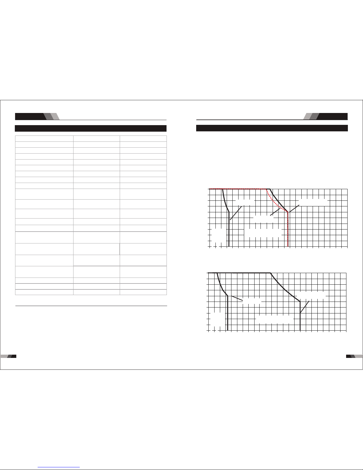
86
87
MULTIFUNCTION SERIES EQUIPMENT MULTIFUNCTION SERIES EQUIPMENT
Sum mary
Sum mary
1.4 Specificat ions O2 41/O251
IP2 3
Des cript ion
Wei ght
Pow er Sour ce Dime nsion s
Coo ling
Wel der Typ e
Eur opean S tanda rds
Num ber of Ph ases
Nom inal Su pply Vol tage
Nom inal Su pply Fr equen cy
Wel ding C urrent Ran ge
(DC S TICK Mo de)
Wel ding C urrent Ran ge
(DC T IG Mod e)
Wel ding C urrent Ran ge
(CU T Mod e)
Sin gle Pha se Gene rator
Req uirem ent
STI CK (MMA )
Wel ding O utput , 40ºC, 1 0 min.
TIG ( GTAW)
Wel ding O utput , 40ºC, 1 0 min.
CUT
Wel ding O utput , 40ºC, 1 0 min.
Ope n circu it volt age (MM A/TIG )
Ope n circu it volt age(CUT )
Pro tecti on Clas s
Max imum In put Cur rent
Effective Input Current
O24 1
20. 9 kg
H39 5mmxW 180mm xD370 mm
Fan C ooled
Inv erter P ower So urce
EN 60 974-1 / I EC 6097 4-1
1
230 V +/- 15%
50/ 60Hz
10 - 17 0A
10 - 17 0A
15 - 40 A
26. 2A
33. 9A
11.7 kVA
200 A @ 50% , 28V
141 A @ 100 %, 25. 6V
170 A @ 60% , 26.8 V
132 A @ 100 %, 25. 3V
170 A @ 60% , 16.8 V
124 A @ 100 %, 15V
200 A @ 50% , 18V
141 A @ 100 %, 15. 6V
40A @ 60 %, 96V
31A @ 10 0%, 92. 4V
40A @ 60 %, 96V
31A @ 10 0%, 92. 4V
66V D C
236 V DC
IP2 3
O25 1
31 kg
Fan C ooled
Inv erter P ower So urce
EN 60 974-1 / I EC 6097 4-1
1
230 V +/- 15%
50/ 60Hz
10 - 20 0A
10 - 20 0A
20 - 40 A
29. 5A
41. 7A
14. 4KVA
66V D C
270 V DC
H54 0mmxW 270mm xD450 mm
1.5 Duty Cy cle
The r ated duty cyc le of a We lding Power S ourc e, is a st atem ent of t he time it may be
ope rate d at its r ated w eldi ng cur rent o utpu t with out exceeding the tempe ratu re lim its of
th e insul ati on of th e co mpo nen t pa rts . To ex pla in t he 1 0 mi nu te d uty cy cle per iod the
fo llo win g exa mpl e is u sed . Sup pos e a Wel din g Pow er So urc e is de sig ned t o ope rat e at
a 5 0% d uty cyc le, 200 amper es at 28 v ol ts. T his mea ns t hat it h as b ee n de sig ned and
bu ilt t o provi de th e rat ed a mpe rag e (2 00 A) f or 5 m inu te s, i .e. arc wel din g ti me , ou t of
ev ery 1 0 min ute p eri od (5 0% o f 10 mi nut es is 5 min ute s). Dur ing t he ot her 5 m inu tes o f
th e 10 mi nut e pe ri od th e Wel din g Po wer Sou rce m ust i dle a nd be all ow ed to coo l. Th e
the rmal cu t out wil l opera te if the d uty cyc le is exc eeded .
Not e 3: Moto r start f use s or the rmal c ircui t break ers are r eco mmen ded fo r this ap plica tion.
Che ck lo cal re quir ement s for you r sit uati on in th is rega rd.
Due t o varia tions t hat can o ccur in m anufa cture d produ cts, cl aimed p erfor mance , volta ges ,
rat ings, a ll capa citie s, meas ureme nts, di mensi ons and w eight s quote d are app roxim ate
onl y. Achieva ble ca pacitie s and ra tings in us e and op eration w ill de pend upon c orre ct
ins talla tion, u se, app licat ions, m ainte nance a nd serv ice.
Duty Cyc le( PERCENTA GE)Duty Cyc le( PERCENTA GE)
Weldi ng Curr ent(A MPS)Weldi ng Curr ent(A MPS)
2525
5050
7575
100100 1 25125 15 015 0 17 51 75
00
101 0
202 0
303 0
404 0
505 0
606 0
707 0
808 0
909 0
10 0100
20 020 0 2252 25 25 025 0 27527 5 30 03 0000
Saf e
Ope ratin g
Reg ion
(CU T)
O24 1 CUT
O24 1 TIG
O24 1 STICK
Not e 1: The Ef fect ive In put Cur rent sh ould be u sed for t he dete rmina tion of c able si ze &
sup ply r equi reme nts .
Not e 2: Gene rator R equir ement s at the Ma ximum O utput D uty Cyc le.
Duty Cyc le( PERCENTA GE)
Weldi ng Curr ent(A MPS)
2525
5050
7575
100100 1 251 25 1501 50 1 75175
00
101 0
202 0
303 0
404 0
505 0
606 0
707 0
808 0
909 0
10 01 00
20 020 0 2252 25 25 025 0 27527 5 30 03 0000
Saf e
Ope ratin g
Reg ion
(CU T)
O25 1 CUT
O25 1 STICK /TIG
Saf e Opera ting Re gion
(TI G&STI CK)
Saf e Opera ting Re gion
(TI G&STI CK)
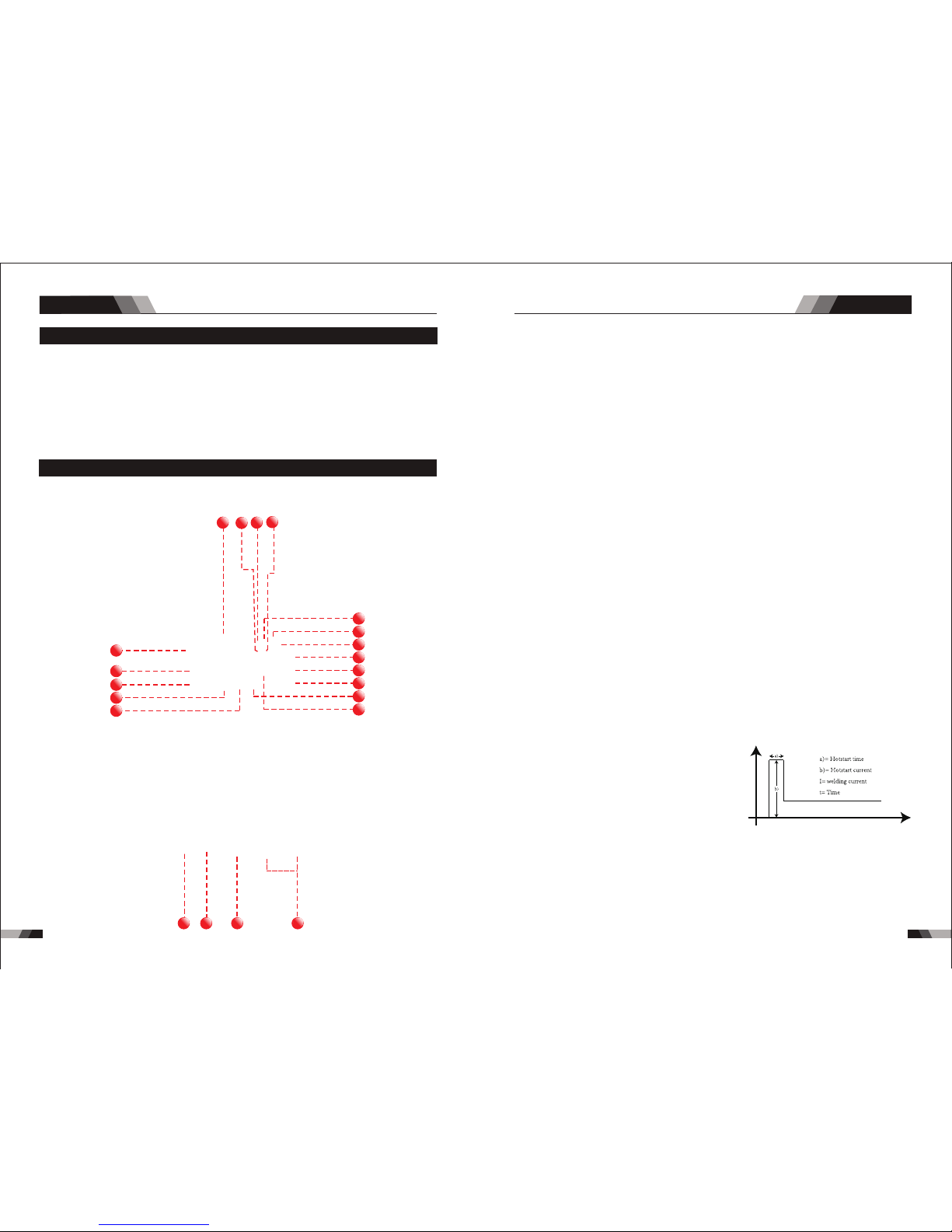
88 89
MULTIFUNCTION SERIES EQUIPMENT MULTIFUNCTION SERIES EQUIPMENT
◆3M Po wer cab le
◆200 Am p Elect rode Ho lder Wi th 3M cab le
◆200 Am p earth C lamp Wi th 3M cab le
◆4M TI G Torch WP2 6
◆Pla sma Torch 4 .5m AG6 0
◆Air R egula tor
◆3.5 M Gas Hos e
◆Ope ratin g Manua l
1.6 Packa ged Ite ms
O241/O251
2.1 Layout For The P anel O2 41
5
12
13
14
16
8
4
3
7
6
2
1
9
10
11
15
17
21
20
19 18
8. Progr amm ing P aramete r Ind ica tors
6. Ti me In dic ator (s)
7. Frequ enc y Ind icator (H z)
The se ind icat or lig hts wil l illu mina te whe n prog ramming.
Time i ndic ator , w hen se tting progr amm in g as pre -flo w, up slop e, dow n slop e and gas
pos t-fl ow, thi s indic ator w ill be o n.
Fre quen cy ind icator, when the se tting program m in pul se fre quen cy ,th is ind icat or wil l
be on .
2. Curre nt In dic ator
Whe n setti ng prog ramm in t he peak c urren t, base c urren t, endi ng curr ent and r em , this
cur rent in dicat or will b e on.
3. Perce nta ge In dicator (%)
Per centa ge indi cator, w hen set ting pr ogram m in puls e duty cy cle , thi s indic ator wi ll be
on .
9. Hot Sta rt
Arc force Correc tio n
Hot S tart Fu nctio n relia bly ign ites th e elect rode
and m elts pe rfect ly to ens ure the b est qua lity
eve n at the st art of th e sea m. thi s solu tion ma kes
lac k of fusi on and co ld weld s a thing o f the pas t
and s ignif icant ly redu ces wel d reinf orcem ent.
Adj ust the h ot star t curre nt here a nd the ti me he re.
Dur ing the w eldin g proce ss, arc force p reven ts
t he el ec tr od e s ti ck in g in th e w el d p oo l w it h
inc rease s in curr ent. th is make s it easi er to wel d
lar ge-dr op mel ting el ectro de typ es at low curren t
str ength s with a sh ort arc i n parti cular.
I
t
5. Therm al Ov erl oad Indic ato r Lig ht
Thi s weld ing pow er sour ce is pro tecte d by a self r esett ing the rmost at. The i ndic ator wi ll
illumi nat e if the d uty c ycle o f the p ower s ourc e has be en ex ceed ed. S houl d the th erma l
ov erl oad indic ator i llu min ate t he output o f the po wer s our ce wi ll be d isa bled. Once the
po wer s our ce cools down th is lig ht wi ll go O FF an d the o ver t emp era tur e con diti on wil l
au tomatic all y res et. N ote th at the m ain s pow er sw itch s houl d rem ain i n the o n posi tion
su ch that the f an con tin ues t o oper ate th us al low ing th e unit t o coo l suff icie ntl y. Do not
swi tch the u nit off s houl d a therm al over load co nditi on be pre sent.
Ope ratio n
Ope ratio n
4. Power O N Ind ica tor
The PO WER ON i ndicator il lumi nates when th e ON/OF F swit ch is in th e ON pos ition a nd
the c orrec t mains v olt age is p rese nt.
1. Digit al Ammete r / Par ameter me ter
The digita l Ammet er is used to dis play t he actual out put cu rren t of the po wer so urce . It is
als o used to d ispla y Param eters i n Progr ammin g Mode.
De pend ing o n the Progr amm ing Pa ram eter sele cte d, the s tatu s indi cto r adjacen t to th e
Amme ter wil l illum inate t o show th e units o f the pro gramm ing par amete r.
Whe n weldi ng, the Am meter w ill dis play ac tual we lding c urren t.
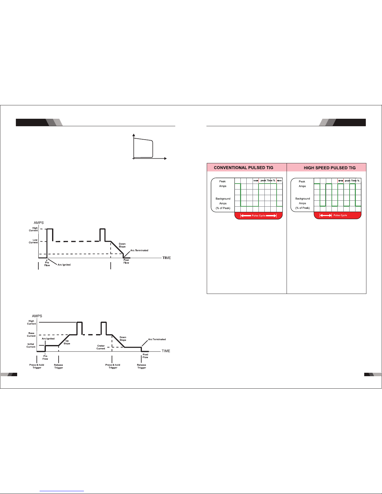
Ant i-sti ck prev ents th e elect rode fr om an neal ing.
If t he el ect rod e sti cks i n sp ite of th e arc ror ce d evi ce , the
mac hi ne au to ma ti ca ll y sw it ch es o ve r t o th e mi ni mum
cu rrent wi th in a bou t 1 se co nd t o pr event th e el ect ro de
f ro m o ve rh ea ti ng . I n or de r to ea si ly s ep ar at e th e
e le ct ro de a nd el ec tr od e h ol de r t o pr ot ec t th e wel de r.
9190
Ope ratio n Ope ratio n
Anti stick
Anti stick
U
I
10. JOB
11. SAVE
You can p ress JO B to sele ct the me mory re cords t hat y ou hav e save d befor e from 1- 9.
Sto re we ldin g func tion an d param eters,c an stor e 1-9 gro ups.
Min imum
Cur rent
Pre ss & hold
Tri gger
Rel ease
Tri gger
13. Proc ess S ele ction But ton
Th e pro ces s sel ect ion c ont rol i s use d to se lec t the d esi red w eld ing m ode . Thr ee
mo des a re av aila ble , MMA ( Sti ck) ,GTAW ( TIG ) and C UT mod es.
14. Pulse Button
Pre ss th e PULS E butt on to t oggl e Puls e On and OF F.
15. Nega tiv e Con trol
16. Posi tiv e Con trol
18. Posi tiv e Welding Te rminal
Po sit ive W eld ing Ter min al. Wel din g cu rre nt f low s fr om th e Pow er S our ce v ia he avy
du ty ba yon et ty pe te rmi nal s. It i s ess ent ial , how eve r, th at th e mal e plu g is i nsert ed
and t urn ed sec urel y to achi eve a sou nd elec trica l conne ction .
MULTIFUNCTION SERIES EQUIPMENT MULTIFUNCTION SERIES EQUIPMENT
Typi cally f rom 1 to 10 P PS. Pro vides a h eatin g
and c oolin g effec t on the w eld pud dle an d can
red uce dis torti on by low ering t he aver age
amp erage . Th is heat ing and c oolin g effec t also
pro duces a d istin ct ripp le patt ern in th e weld
bea d. The re lati onshi p betwe en pul se freq uency
and t ravel s peed de termi nes the d istan ce
bet ween th e rippl es. Slo w pulsi ng can al so be
coo rdina ted wit h fille r metal a dditi on and
inc rease o veral l contr ol of the w eld pud dle
In ex cess of 4 0 PPS, Pu lsed TI G beco mes mor e
aud ible th an visi ble-c ausin g incre ased pu ddle
agi tatio n for a bet ter as- welde d micro struc ture.
Pul sing th e weld cu rrent a t high sp eeds- betwe en
a hig h Peak an d a low Bac kgrou nd ampe ragecan a lso con stric t and foc us the ar c.Thi s resul ts
in ma ximum a rc stab ility, i ncre ased pe netra tion
and i ncrea sed tra vel spe eds(C ommon R ange:
100 -500 PP S).
The Ar c-Sha rpeni ng effe cts of h igh spe ed
pul sing ar e expan ded to ne w dimen sions . The
abi lity to p ulse at 5 ,000P PS furt her enh ances
arc s tabil ity and c oncen trati on pote ntial -whic h
is ex tre mel y benef icial t o autom ation w here
max imum tr avel ts peeds a re requ ired.
No te: t hat w hen o per ating i n GTAW ( HF and LI FT TI G mo des), t he po wer sou rc e wi ll
rem ain act ivate d until t he sele cted do wn slop e time ha s elaps ed
17. Sele cti ng Fu nction Bu tto n
Thi s butt on can se lect di ffere nt pro gramm ing par amete r from No . 8
4T L atc h mo de th is mo de of w eld ing i s mai nly u sed f or long w eld ing r uns t o reduc e
op era tor fat igu e. In thi s mod e the o per ator can p res s and r ele ase the t orc h tri gge r and
th e out put w ill r emai n act ive . To dea cti vate the p owe r sou rce , the tri gge r switc h mus t
ag ain b e pre sse d and rel eas ed, thu s eli mina tin g the n eed f or th e op era tor t o hol d the
to rch t rig ger.
The n egati ve cont rol is us ed to min us sett ing par amete r for sel ected f uncti on from 8 .
The p ositi ve cont rol is us ed to plu s setti ng para meter f or sele cted fu nctio n from 8.
12. Trigge r Mode Cont rol Butto n (HF TIG and L IFT TIG Mod e only)
The t rigg er mod e control is used to swit ch the f unct iona lity o f the to rch tr igge r betw een
2T an d 4T.
out put t o be act ive.
Pre ss an d hold t he tor ch tri gger to a cti vate t he pow er sou rce (we ld) . Rele ase th e torc h
tri gge r swit ch to ce ase weldi ng.
2T N orm al Mo de I n thi s mod e, t he to rch t rigge r must re main pr ess ed fo r the wel din g

9392
Ope ratio n Ope ratio n
21. Shie ldi ng Ga s Outlet
Th e Shi eld ing G as Ou tle t loc ate d on th e fro nt pa nel i s a fas t conn ecti on of a s uita ble
TIG Tor ch.
CAUTION
Lo ose wel ding te rmi nal c onn ect ion s can cau se o ver heati ng a nd re sul t in t he ma le pl ug
be ing fus ed i n the ter min al.
2.2 Control Pane l
.Gas P re- Flo w 1
Abs olut e sett ing r ange 0 .1s to 5 s (0. 1S inc reme nts )
Thi s param eter op erate s in TIG mo des on ly and is u sed to pr ovide g as to the w eld zon e
pri or to str iking t he arc, o nce the t orc h trig ger sw itch ha s been pr essed . Thi s contr ol is
use d to dram atica lly red uce wel d poros ity at th e start o f a weld.
2.Init ial C urr ent
The m ain cur ren t Sett ing ra nge 1 0AMP t o 170A MP
This parameter operates in (4T ) TIG modes o nly and is us ed to set the start cur rent for TI G.
Th e Sta rt Cu rre nt re main s on until t he to rch t rig ger s witc h is released aft er it h as be en
dep resse d.
No te: T he ma ximum in iti al cu rren t ava ila ble w ill b e lim ite d to t he se t val ue of t he ba se
cur ren t.
3.Up Slo pe
Set ting ra nges :0 .1S-1 0S (0 .1S in crem ents)
Thi s para mete r oper ates i n (2T and 4 T) TIG mo des on ly and i s used to set the t ime fo r the
we ld cu rre nt to ramp up, a fte r the t orch tri gge r swi tch h as be en pre ssed the n rel eas ed,
fro m Initi al Curr ent to Hi gh or bas e curre nt.
4.Peak C urr ent
Set ting ra nges
O24 1:10A MP to 170 AMP (D C TIG mo de), 1 0 to 170A (A C HF TIG mo de)
Th is p ara meter s ets t he TI G WEL D cu rre nt. T his p ara met er al so s ets t he ST ICK wel d
cur rent.
5.Base C urr ent
Set ting ra nges
O24 1:10A MP to 170 AMP (D C TIG mo de), 1 0AMP to 1 70AMP (AC HF TIG mod e)
Sec ondar y curre nt (TIG )/pul se paus e curre nt.
6.Down S lop e
Set ting ra nges 0. 1-1 0s
Thi s para mete r oper ates i n TIG mod es onl y and is used to se t the ti me for t he wel d curre nt
to ramp do wn, af ter the torc h trig ger sw itch h as been pre ssed t o end c urre nt. Th is control
is us ed to eli minat e the cra ter tha t can for m at the co mpl etio n of a wel d.
7.End cu rre nt
Set ting ra nges 10 A-170 A
This pa ramete r operate s in (4T) TIG modes only and is used to set the fini sh current for TIG.
The en d Curre nt rema ins ON until the to rch tri gger switch is re lease d after i t has been
dep resse d.
No te: T he maxi mum c rat er cu rre nt av ailabl e wil l be l imi ted t o the s et valu e of th e bas e
cur ren t.
8.Post F low
9. Remot e Con tro l
Set ting ra nges 1- 10S
The s ystem i ndepe ndent ly iden tifie s the rem ote con trol, a nd when t he indi cator l ight is
on, t he weld ing cur rent ca n be adju sted by r emote ( foot or w eldin g gun).
Th is p ara met er op era tes i n TIG mod es o nly a nd is u sed to ad jus t the pos t ga s flo w
ti me o nce t he ar c has ext ing uis hed . Thi s con tro l is used t o dr ama tic all y red uce
ox ida tio n of t he tu ngs ten e lec tro de.
10.Pul se Wi dth
Set ting ra nges 10 %-90%
Th is p ara met er s ets the per ce nta ge o n ti me o f the PUL SE FR EQU ENC Y f or Hi gh
we ld cu rre nt w hen the P ULS E is O N.
11.Puls e Fre que ncy
Set ting ra nge s 1HZ -2 00HZ
Thi s param eter se ts th e PULS E FREQ UEN CY whe n the PU LSE is O N.
MULTIFUNCTION SERIES EQUIPMENT MULTIFUNCTION SERIES EQUIPMENT
19. Nega tiv e Welding Te rminal
Ne gat ive W eld ing Te rmi nal . Wel din g cur ren t flo ws fr om th e Pow er So urce via h eav y
du ty ba yon et t ype t erm ina ls. I t is es sen tia l, ho wev er, t hat the mal e pl ug is ins ert ed
and t urn ed sec urel y to achi eve a sou nd elec trica l conne ction .
20. 5 Pin Co ntr ol So cket
The 5 pin rece ptac le is us ed to co nnec t a trig ger switch or r emot e cont rol to t he wel ding
Pow er Sour ce circ uit ry:
To make connectio ns, align ke yway, insert plug, and rota te thread ed collar fu lly clock wise.
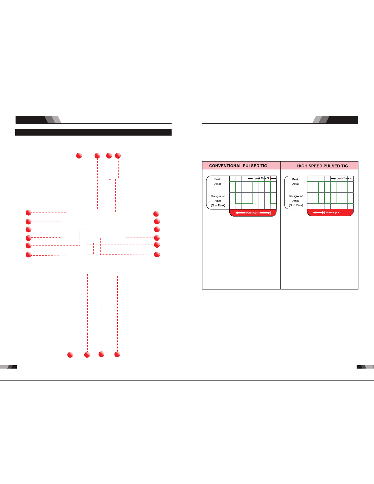
9594
Ope ratio n Op erati on
MULTIFUNCTION SERIES EQUIPMENT MULTIFUNCTION SERIES EQUIPMENT
2.3 Layout For The P anel O2 51
10
11
12
13
14
15
9
8
7
6
5
4
3
2
1
16
17 18
19
20
1. RE SET b utt on
Whe n softw are h as pro blem p lease t rigge r RESET b utto n.
2. Pu lse B utton
Pre ss the PU LSE b utto n to tog gle P ulse O n and OF F.
.
Typi cally f rom 1 to 10 P PS. Pro vides a h eatin g
and c oolin g effec t on the w eld pud dle an d can
red uce dis torti on by low ering t he aver age
amp erage . Th is heat ing and c oolin g effec t also
pro duces a d istin ct ripp le patt ern in th e weld
bea d. The re lati onshi p betwe en pul se freq uency
and t ravel s peed de termi nes the d istan ce
bet ween th e rippl es. Slo w pulsi ng can al so be
coo rdina ted wit h fille r metal a dditi on and
inc rease o veral l contr ol of the w eld pud dle
In ex cess of 4 0 PPS, Pu lsed TI G beco mes mor e
aud ible th an visi ble-c ausin g incre ased pu ddle
agi tatio n for a bet ter as- welde d micro struc ture.
Pul sing th e weld cu rrent a t high sp eeds- betwe en
a hig h Peak an d a low Bac kgrou nd ampe ragecan a lso con stric t and foc us the ar c.Thi s resul ts
in ma ximum a rc stab ility, i ncre ased pe netra tion
and i ncrea sed tra vel spe eds(C ommon R ange:
100 -500 PP S).
The Ar c-Sha rpeni ng effe cts of h igh spe ed
pul sing ar e expan ded to ne w dimen sions . The
abi lity to p ulse at 5 ,000P PS furt her enh ances
arc s tabil ity and c oncen trati on pote ntial -whic h
is ex tre mel y benef icial t o autom ation w here
max imum tr avel ts peeds a re requ ired.
3. Trigger Mod e Con tro l But ton ( HF TIG and LIFT TI G Mod e onl y)
The trig ger mo de control i s used to swi tch th e function alit y of the t orch t rigger be twee n
2T an d 4T.
ou tput t o be ac tive .
Pr ess an d hol d the to rch t rigg er to ac tiva te th e power sou rce ( weld ). Re leas e the t orch
tr igge r swi tch to c eas e weld ing.
2T N orm al M ode In th is mo de, t he to rch t rig ger mus t rem ain p re sse d for t hew el din g

96 97
Ope ratio n Ope ratio n
MULTIFUNCTION SERIES EQUIPMENT MULTIFUNCTION SERIES EQUIPMENT
4. Proce ss Se lec tion Butt on
Th e pro ces s sel ect ion c ont rol i s use d to se lec t the d esi red w eld ing m ode . Thr ee
mod es are av ailab le, GTAW (T IG) , MMA (St ick) a nd CU T mode s.
No te: t hat w hen o per ating i n GTAW ( HF and LI FT TI G mo des), t he po wer sou rc e wi ll
rem ain act ivate d until t he sele cted do wn slop e time ha s elaps ed
Min imum
Cur rent
Pre ss & hold
Tri gger
Rel ease
Tri gger
cur rent of t he po wer so urce .
At ti mes of n on-w eldi ng, t he amp erag e mete r wil l display a p re- set (p revi ew) am per age
val ue. Thi s valu e can be ad juste d by vary ing the m ultif uncti on cont rol whe n the
Pro gramm ing Par amete r Indic ator li ght sho ws BASE C URREN T.
5. Digit al Ammete r
The digital ampe rage m eter i s used to d ispl ay bot h the pr e-set curre nt and a ctua l outp ut
4T L atc h mo de th is mo de of w eld ing i s mai nly u sed f or long w eld ing r uns t o reduc e
op era tor fat igu e. In thi s mod e the o per ator can p res s and r ele ase the t orc h tri gge r and
th e out put w ill r emai n act ive . To dea cti vate the p owe r sou rce , the tri gge r switc h mus t
ag ain b e pre sse d and rel eas ed, thu s eli mina tin g the n eed f or th e op era tor t o hol d the
to rch t rig ger.
6. Digit al Vol tmeter / Pa ram eter Meter
The di gita l volt me ter is us ed to dis play th e actual outp ut volt age of th e power sourc e. It is
als o used to d ispla y Param eters i n Progr ammin g Mode.
De pend ing o n the Progr amm ing Pa ram eter sele cte d, the s tatu s indi cto r adjacen t to th e
vol t meter w ill ill umina te to sho w the uni ts of the p rog ramm ing pa ramet er.
Whe n weldi ng, the v olt met er will d ispla y actua l weldi ng volt age.
7. Power O N Ind ica tor
The PO WER ON i ndicator il lumi nates when th e ON/OF F swit ch is in th e ON pos ition a nd
the c orrec t mains v olt age is p rese nt.
8. Therm al Ov erl oad Indic ato r Lig ht
Thi s weld ing pow er sour ce is pro tecte d by a self r esett ing the rmost at. The i ndic ator wi ll
illumi nat e if the d uty c ycle o f the p ower s ourc e has be en ex ceed ed. S houl d the th erma l
ov erl oad indic ator i llu min ate t he output o f the po wer s our ce wi ll be d isa ble d. Once the
po wer s our ce cools down th is lig ht wi ll go O FF an d the o ver t emp era tur e con diti on wil l
au tomatic all y res et. N ote th at the m ain s pow er sw itch s houl d rem ain i n the o n posi tion
su ch that the f an con tin ues t o oper ate th us al low ing th e unit t o coo l suff icie ntl y. Do not
swi tch the u nit off s houl d a therm al over load co nditi on be pre sent.
9. JOB and S AVE
You ca n pre ss JO B to se lect t he me mor y rec ord s tha t you h ave s ave d bef ore f rom 1 -9.
For t he ne w sett ing of p resen t base cu rrent Am ps ,jus t pre ss SAVE .
10. Prog ram min g Paramet er In dic ators
The se ind icato r light s will il lumin ate whe n progr ammin g.
12. Mode B utt on
Pre ss th e MODE b utto n to to ggle AC a nd DC ou tput in L IFT TIG , HF TIG a nd STI CK.
13. Forw ard P rog ramming B utt on
Pre ssi ng thi s butt on will a dvanc e to the ne xt step i n the pro gramm ing seq uence .
14. Back P rog ram ming Butt on
Pre ssi ng thi s butt on will g o back to t he prev ious st ep in the p rogra mming s equen ce.
15. Posi tiv e Con trol
16. Nega tiv e Con trol
17. Posi tiv e Welding Te rminal
Po sit ive W eld ing Ter min al. Wel din g cu rre nt f low s fr om th e Pow er S our ce v ia he avy
du ty ba yon et ty pe te rmi nal s. It i s ess ent ial , how eve r, th at th e mal e plu g is i nsert ed
and t urn ed sec urel y to achi eve a sou nd elec trica l conne ction .
11. HF Butt on
Pres s and hold the HF butt on to purge the gas li ne in LIF T TIG an d HF TIG modes. To HF
the shie ldi ng gas l ine i n LIFT T IG and H F TI G mode s pre ss the H F but ton an d rele ase.
18. 5 Pin Co ntr ol So cket
The 5 pin rece ptac le is us ed to co nnec t a trig ger switch or r emot e cont rol to t he wel ding
Pow er Sour ce circ uit ry:
To make connectio ns, align ke yway, insert plug, and rota te thread ed collar fu lly clock wise.
The p ositi ve cont rol is us ed to plu s setti ng para meter f or sele cted fu nctio n from 10 .
The n egati ve cont rol is us ed to min us sett ing par amete r for sel ected f uncti on from 1 0.

9998
Ope ratio n
Ope ratio n
MULTIFUNCTION SERIES EQUIPMENT MULTIFUNCTION SERIES EQUIPMENT
2.Init ial C urr ent
The m ain cur ren t Sett ing ra nge 1 0AMP t o 200A MP
This p aramet er opera tes in (4T ) TIG modes on ly and is use d to set the st art curr ent for TIG .
Th e Sta rt Cu rre nt re main s on u nti l the t orc h tri gge r swi tch is released af ter i t has b een
dep resse d.
No te: T he m axi mum i nitial c urr ent ava ila ble wil l be li mit ed to t he se t val ue of t he ba se
cur ren t.
3.Up Slo pe
Set ting ra nges :0 .1S-1 0S (0 .1S in crem ents)
Thi s para meter o pera tes in (2 T and 4T) T IG mode s only and is use d to set th e time for the
we ld cu rre nt to ramp up, a fte r the t orch trigger swi tch h as be en pr esse d then rel eas ed,
fro m Initi al Curr ent to Hi gh or bas e curre nt.
4.Peak C urr ent
Set ting ra nges
O25 1:10A MP to 200 AMP ( DC TIG a nd AC HF T IG) ,10-2 00A( Sti ck mode)
Th is p ara met er se ts t he TI G WE LD cu rrent. T his par ame ter a lso set s the STI CK w eld
cur rent.
.Gas Pre-Fl ow 1
Abs olut e sett ing r ange 0 .1s to 2 0s (0 .1S in crem ent s)
Thi s param eter op erate s in TIG mo des on ly and is u sed to pr ovide g as to the w eld zon e
pri or to str iking t he arc, o nce the t orc h trig ger sw itch ha s been pr essed . Thi s contr ol is
use d to dram atica lly red uce wel d poros ity at th e start o f a weld.
2.4 Control Pane l
CAUTION
Lo ose wel ding te rmi nal c onn ect ion s can cau se o ver heati ng a nd re sul t in t he ma le pl ug
be ing fus ed i n the ter min al.
20. Shie ldi ng Ga s Outlet
Th e Shi eld ing G as Ou tle t loc ate d on th e fro nt pa nel i s a fas t conn ecti on of a s uita ble
TIG Tor ch.
19. Nega tiv e Welding Te rminal
Ne gat ive W eld ing Te rmi nal . Wel din g cur ren t flo ws fr om th e Pow er So urce via h eav y
du ty ba yon et t ype t erm ina ls. I t is es sen tia l, ho wev er, t hat the mal e pl ug is ins ert ed
and t urn ed sec urel y to achi eve a sou nd elec trica l conne ction .
5.Base C urr ent
Set ting ra nges
O25 1:10A MP to 200 AMP (D C TIG mo de), 1 0AMP to 2 00AMP (AC HF TIG mode)
6.Puls e Wid th
Set ting ra nges 10 %-90%
Th is pa ram eter set s the p erc enta ge on t ime o f the PUL SE FR EQU ENC Y for H igh w eld
cur rent wh en the PU LSE is ON .
7.Puls e Fre que ncy
Set ting ra nge s 1HZ -2 00HZ
Thi s param eter se ts the PU LSE F REQU ENCY w hen th e PULSE i s ON.
8.Down S lop e
Set ting ra nges 0. 1-10s
Thi s parameter o pera tes in TI G modes o nly and i s used to set the t ime for t he weld c urre nt
to r amp d own, a fter t he to rch t rigg er swi tch h as be en pre ssed t o end c urr ent. T his c ont rol
is us ed to eli minat e the cra ter tha t can for m at the co mpl etio n of a wel d.
9.End cu rre nt
Set ting ra nges 10 A-200 A
This paramet er operat es in (4T) TIG modes only an d is used to set the finish cu rrent fo r TIG.
The e nd curr ent rem ains ON until t he torc h trigg er swit ch is release d after i t has bee n
dep resse d.
No te: T he ma xim um crat er cu rre nt av ail abl e wil l be l imi ted t o the set v alu e of th e ba se
cur ren t.
Sec ondar y curre nt (TIG )/pul se paus e curre nt.
AC Fr equen cy cont rol
Con trols t he widt h of the ar c cone. I ncrea sing th e AC fr eque ncy pr ovides a mor e focu sed
arc w ith inc rease d direc tiona l contr ol.
No te: D ecr eas ing t he AC F req uen cy so fte ns the a rc a nd b roade ns th e we ld p uddle
f or a w id er w eld be ad.
11. AC F requency
Set ting ra nges 50 HZ-20 0HZ
Th is pa rame ter op era tes i n AC TIG m ode o nly a nd is u sed t o set t he fr eque ncy fo r the
AC we ld cu rre nt.
10. Post F low
Set ting ra nges 1- 20S
Th is p ara met er op era tes i n TIG mod es o nly a nd is u sed to ad jus t the pos t ga s flo w
ti me on ce the ar c has e xti ngu ish ed. T his c ont rol i s use d to d ram ati cal ly re duc e
ox ida tio n of t he tu ngs ten e lec tro de.
Wid er bead , good pe netra tion
ide al for bu ildup w ork
Nar rower b ead for f illet w elds an d
aut omate d appli catio ns

10 110 0
Ope ratio n Opera tion
MULTIFUNCTION SERIES EQUIPMENT MULTIFUNCTION SERIES EQUIPMENT
AC Ba lance C ontro l
Co ntr ols a rc cl ean ing a ction. Ad jus ting the % E N of th e AC wav e cont rol s the w idth o f the
etc hing zo ne surr oundi ng the we ld.
No te : Se t the A C Ba lan ce co ntr ol f or a deq uat e ar c cl ean ing a cti on a t th e si des and in
fr ont of t he w el d pu dd le . AC B al an ce s hou ld b e fi ne t uned a cc or ding t o ho w he av y or
thi ck the ox ides ar e.
Wid er bead , good pe netra tion
ide al for bu ildup w ork
Nar rower B ead, Go od Pene trati on
Ide al For Bu ildup W ork
Wid er bead a nd clea ning ac tion Nar rower b ead, wi th no vis ible cl eanin g
Wid er bead a nd clea ning ac ting Nar rower b ead and c leani ng acti ng
12.Wave Balance
Set ting ar range s 10%-5 0%
Thi s para mete r oper ates i n AC TI G mode and is use d to set t he pen etra tion t o clea ning
act ion ra tio fo r the AC weld current. G ener ally WAVE BALANC E is set t o 50% fo r AC
the WAV E BALA NCE co ntro l is set to 1 0%. Ma ximu m clea ning o f heav ily ox idis ed
alu mini um or ma gnes ium al loys i s achi eved when the W AVE BALA NCE co ntro l is set to
50%
Ant istic k
Ant istic k
U
I
13. Hot St art
14. Ar cforce Co rre cti on
Hot S tart Fu nctio n relia bly ign ites th e elect rode
and m elts pe rfect ly to ens ure the b est qua lity
eve n at the st art of th e sea m. thi s solu tion ma kes
lac k of fusi on and co ld weld s a thing o f the pas t
and s ignif icant ly redu ces wel d reinf orcem ent.
Adj ust the h ot star t curre nt here a nd the ti me he re.
Dur ing the w eldin g proce ss, arc force p reven ts
t he el ec tr od e s ti ck in g in th e w el d p oo l w it h
inc rease s in curr ent. th is make s it easi er to wel d
lar ge-dr op mel ting el ectro de typ es at low curren t
str ength s with a sh ort arc i n parti cular.
Ant i-sti ck prev ents th e ele ctro de fro m ann eali ng.
If t he el ect rod e sti cks i n sp ite of th e arc ror ce d evi ce , the
mac hi ne au to ma ti ca ll y sw it ch es o ve r t o th e mi ni mum
cu rrent wi th in a bou t 1 se co nd t o pr event th e el ect ro de
e le ct ro de a nd el ec tr od e h ol de r t o pr ot ec t th e wel de r.
2.5 Setup For STIC K (MMA) Welding O241
WAR NIN G
Be fo re c onn ectin g th e wo rk c lam p to th e wo rk a nd
in ser tin g the ele ctr ode i n the ele ctr ode h old er ma ke
sur e the mai ns powe r sup ply is s witc hed o ff.
CA UTI ON
CA UTI ON
Re mov e any p ack agi ng m ate ria l pri or to use . Do n ot
bl ock the a ir ve nts a t the f ron t or rear o f th e Wel din g
Pow er Sour ce.
Lo os e we ldi ng t erm in al c on ne ct io ns c an c aus e
ov erh eat ing a nd resu lt i n th e ma le p lug bei ng fu sed
in th e bayon et te rmin al.
Fo r Alk alin e Elec tro de, con nec t the e lec trod e hold er to t he po sit ive w eld ing termi mal
El ectr ode, please c onne ct th e ele ctrode ho lder t o the n egat ive w elding termi mal a nd
ma nufa ctur er. We ldin g curr ent f low s from the Po wer So urc e via h eavy duty b ayon et ty pe
te rmin als. I t is es sen tial, how eve r, tha t the m ale p lug i s inserte d and t urn ed se curely to
ac hiev e a soun d ele ctr ical conn ecti on. S elect STI CK mo de wi th th e pro cess sele cti on
co ntro l.
a nd c on ne ct th e wo rk le ad to th e neg at iv e w el di ng te rm in al , wh il e f or th e A ci d
con nect the wor k lead to the po sitve welding t ermi nal. If in d oubt c onsu lt the e lect rode
cle anin g action of the AC TI G weld ing arc . Maxi mum weld pene trat ion is ac hiev ed whe n
ST IC K we ldi ng . Th e WAV E BA LA NC E co nt rol ch an ge s th e ra tio of p enetratio n to
f ro m o v er h e at i n g. In or d er to ea s il y se p ara t e t h e
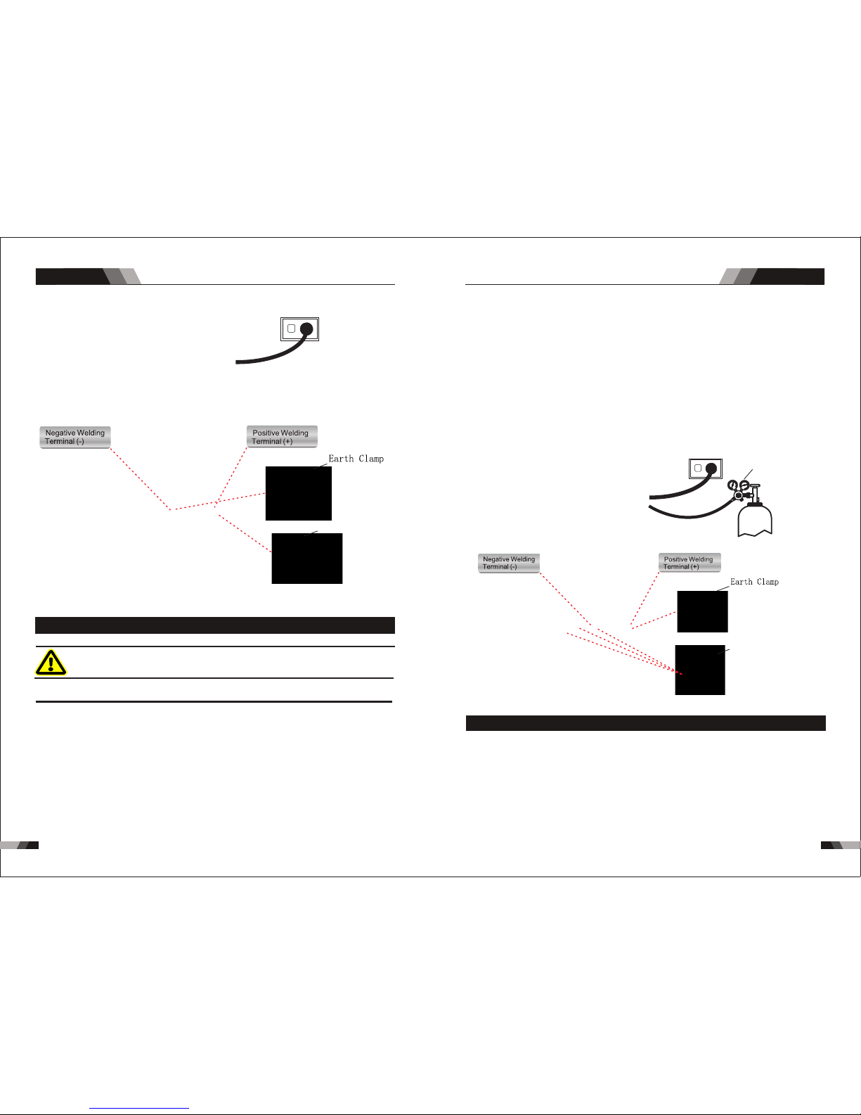
10 310 2
Ope ratio n
Ope ratio n
MULTIFUNCTION SERIES EQUIPMENT MULTIFUNCTION SERIES EQUIPMENT
pow er supp ly
Ele ctrod e holdd er
2.6 Set-up For LIF T TIG (GTAW) Wel ding O2 41
WAR NIN G
Bef ore any w eldin g is to b egin , be sur e to we ar all
app ropri ate and r eco mmen ded sa fety eq uipme nt.
NO TE
The f ollow ing set u p is know n as Stra igh t Pola rity o r DC elec trode p ositi ve. Thi s is
com monly u sed for D C LIFT TI G weld ing on m ost mat erial s such as s teel an d stain less
ste el.
1. Sw itch th e ON/OF F Swi tch (l ocat ed on t he rea r pane l) to OFF.
2. Co nnect t he work l ead cab le to the p ositi ve outp ut term inal, a nd the LI FT TIG Torch
cab le to the n egati ve outp ut term inal.
3. Co nnect t he gas li ne/ho se to the p roper s hield ing gas s ource .
4. Sl owly op en the Arg on Cyli nder Val ve to th e fully o pen pos ition .
5. Co nnect t he work l ead cla mp to you r work pi ece.
6. Th e tung sten mu st be gro und to a bl unt poi nt (sim ilar to a p encil ) in orde r to achi eve
opt imum we lding r esult s. See il lustr ation . It is cri tic al to gr ind th e tungs ten ele ctrod e
in th e direc tion th e grind ing whe el is tur ning. G rind at a 3 0 degre e angle a nd neve r
to a sh arp poi nt.
7. In stall t he tung sten wi th appr oxima tely 1. 6mm to 3. 2mm s tick ing ou t from th e
gas c up, ens uring y ou have c orrec t sized c ollet .
8. Tig hten th e back ca p.
9. Tur n the swi tch to th e “ON” po sitio n. The po wer L. E.D. li ght sho uld ill umina te.
10. S et the we lding p roces s to LIFT T IG.
11. Se t the We ld Cur rent Co ntrol K nob to th e desir ed ampe rage.
12. You are no w read y to begin LI FT TIG We lding.
Ar./ GAS(T IG/WI G)
pow er supp ly
TIG t orch
2.7 Setup For Cutt ing (CU T) O241
In or der fo r the uni t to fun ctio n correctly, i t must be i nsta lled p rope rly. Fol low th e proce dure
giv en bel ow for co rrec t inst alla tion :
1. R ead th e saf ety ru les gi ven i n this m anua l car eful ly.
2. C heck o n rec eivi ng the u nit t hat th ere ar e no de fect ive pa rts or pa rts d amag ed dur ing
tra nspor tatio n.
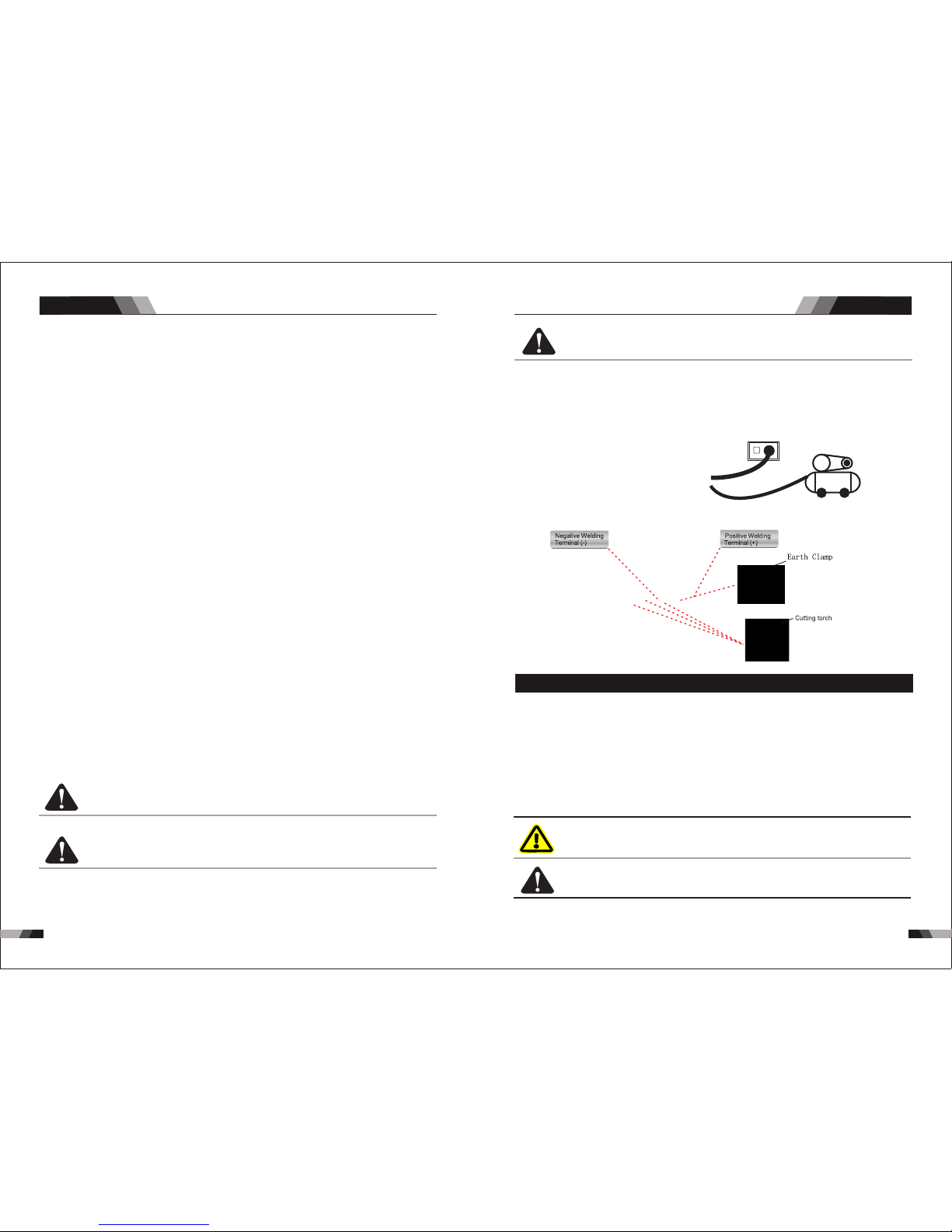
10 510 4
Ope ratio n Op erati on
2.8 Setup For STIC K (MMA) Welding O251
MULTIFUNCTION SERIES EQUIPMENT MULTIFUNCTION SERIES EQUIPMENT
WAR NIN G
CA UTI ON
Be fo re c onn ectin g th e wo rk c lam p to th e wo rk a nd
in ser tin g the ele ctr ode i n the ele ctr ode h old er ma ke
sur e the mai ns powe r sup ply is s witc hed o ff.
Re mov e any p ack agi ng m ate ria l pri or to use . Do n ot
bl ock the a ir ve nts a t the f ron t or rear o f th e Wel din g
Pow er Sour ce.
Fo r Alk alin e Elec tro de, con nec t the e lec trod e hold er to t he po sit ive w eld ing termi mal
El ectr ode, please c onne ct th e ele ctrode ho lder t o the n ega tiv e wel ding term imal a nd
ma nufa ctur er. We ldin g curr ent f low s from the Po wer So urc e via h eavy duty b ayon et ty pe
te rmin als. I t is es sen tial, how ever, t hat t he ma le pl ug is i nser ted an d tur ned s ecur ely to
ac hiev e a soun d ele ctr ical conn ecti on. S elect STI CK mo de wi th th e pro cess sele cti on
co ntro l.
a nd c on ne ct th e wo rk le ad to th e neg at iv e w el di ng te rm in al , wh il e f or th e A ci d
con nect the wor k lead to the po sitve wel ding t ermi nal. If in d oubt c onsu lt the e lect rode
pow er supp ly
Air c ompre ssor
3. A ttac h air re gulator as sh ow in pi ctur e Air R egul ator I nsta llat ion on ly for O 241.
4. S et you r unit up i n an are a whic h is ade quat ely ventilated an d make s ure th at the a ir
ven ts are n ot obs truc ted.
5. C onne ct the power su pply c able t o a sock et loc ated as near as p ossi ble to t he wor k area ,
so th at the u nit ca n be swit ched o ff qui ckly in case of e merg ency.
6. You r machine has a 1 6 amp pl ug fit ted, b efore use che ck tha t the gr een/ yell ow ear th is
con nect ed to th e eart h pin soc ket of f itte d plug .
7. M ake sure that t he mai ns sup ply sw itch a nd any fuses ha ve a val ue whi ch ± 15% t he
max imum c urre nt abs orbe d by the un it. All f uses s houl d be the slow-blow ty pe.
8. An y extensions of pow er sup ply ca ble sh ould h ave th e same cr oss- sect ion as t he pow er
sup ply ca ble. The exte nsio n lead s, how ever, s houl d only be used wh en abs olut ely
nec essa ry. It is im port ant to n ote th at any extension of m ains c able s or tor ch cab les will
pos sibl y affect the cu ttin g perf orma nce of t his cu ttin g equipment, due to t he fac t that t he
res ista nce of t he cab le will reduc e volt age in put, w hich i s dete rmin ed by the l engt h of the
cab le. Th e supplied le ngth o f main c able s and to rch cables is r ecom mend ed.
9. F aste n the earth cla mp to th e piec e to be cu t, If the s urfa ce of th e piec e to be cut i s
pai nted , rust y or cov ered with ins ulat ing ma teri al, cl ean th e surf ace so th at
sat isfa ctor y cont act be twee n the pie ce and t he ear th cla mp can b e obtained.
10. Make s ure th at the t orch has been a ssem bled w ith th e corr ect co mpon ents and that t he
cut ting t ip is su itab le for th e cutt ing cu rren t.
11. Co nnec t air to r egul ator a nd adj ust regulator to de live r 5-6 ba r 90lt r/mi n
12. Swit ch the u nit on u sing the main s witc h loca ted on t he bac k side .
CA UTI ON
CA UTI ON
CA UTI ON
Do n ot po int the t orc h jet a t for eig n bod ies .
Av oid un ne ce ss ar y li ght in g of the pi lo t ar c to pre ve nt e xce ss iv e
co ns um pt io n of the el ec tr od ea nd n oz zl e.
Du rin g cut tin g the spe ed of t he to rch m ovem ent should be i n acc ord anc e wit h the
th ick nes s of th e piec e to be c ut. E xce ssi ve spe ed ca use s a ret urn o f inc ande scen t
to war ds th e tor ch whi ch sh ort ens t he li fe of t he pa rts o f the t orc h most sub jec t to
wear and tear. The m etal fou ling on th e nozzle s hould be removed a s soon as pos sible .
13 . C onta ct th e cop per t ip of t he to rch t o the w ork p iece, pre ss the b utto n of th e for ch un til
th e cut ting oper atio n.
the ar c-sta rting a nd raise t he cutti ng torc h about 1m m above th e work pie ce, and perform
14. Onc e cutt ing is o ver, rel ease th e torch b utton t o put out t he arc. A per iod of po st-fl ow
tim e 45 to 7 5 seco nds (r equ ired f or tor ch co olin g) wil l follo w. Do not di sconn ect air
unt il th is coo ling p eriod h as been c omple ted. Fa ilure t o do this w ill res ult in to rch hea d
dam age.

10 710 6
2.9 Set-up For LIF T TIG (GTAW) Wel ding O2 51
WAR NIN G
Bef ore any w eldin g is to b egin , be sur e to we ar all
app ropri ate and r eco mmen ded sa fet y equi pmen t.
NO TE
Ope ratio n
Ope ratio n
The f ollow ing set u p is know n as stra ight po larit y or DC ele ctrod e posit ive. Th is is
com monly u sed for D C LIFT TI G weld ing on m ost mat erial s such as s teel an d stain less
ste el.
1. Sw itch th e ON/OF F swi tch (l ocat ed on t he rea r pane l) to OFF.
2. Co nnect t he work l ead cab le to the p ositi ve outp ut term inal, a nd the LI FT TIG to rch
cab le to the n egati ve outp ut term ina l.
3. Co nnect t he gas li ne/ho se to the p roper s hield ing gas s ource .
4. Sl owly op en the Arg on cyli nder va lve to th e fully o pen pos ition .
2.10 Setu p For Cut ting (C UT) O251
In or der for t he unit t o funct ion c orre ctly, i t must b e ins tall ed pro perly. F ollo w the pro cedur e
giv en belo w for cor rect in stall ation :
pow er supp ly
Ar./ GAS(T IG/WI G)
TIG torc h
MULTIFUNCTION SERIES EQUIPMENT MULTIFUNCTION SERIES EQUIPMENT
pow er supp ly
Ele ctrod e holdd er
CA UTI ON
Lo os e we ldi ng t erm in al c on ne ct io ns c an c aus e
ov erh eat ing a nd resu lt i n th e ma le p lug bei ng fu sed
in th e bayon et te rmin al.
1. R ead th e saf ety ru les gi ven i n this m anua l car eful ly.
2. C heck o n rec eivi ng the u nit t hat th ere ar e no de fect ive pa rts or pa rts d amag ed dur ing
tra nspor tatio n.
3. A ttac h air r egul ator a s sho w in pic ture Ai r Reg ulat or Ins talla tion on ly for O2 51.
5. Co nnect t he work l ead cla mp to you r work pi ece.
6. Th e tung sten mu st be gro und to a bl unt poi nt (sim ilar to a p encil ) in orde r to achi eve
opt imum we lding r esult s. See il lustr ation . It is cri tic al to gr ind th e tun gste n elec trode
in th e direc tion th e grind ing whe el is tur ning. G rind at a 3 0 degre e angle a nd neve r
to a sh arp poi nt.
7. In stall t he tung sten wi th appr oxima tely 1. 6mm to 3. 2mm s tick ing ou t from th e
gas c up, ens uring y ou have c orrec t sized c ollet .
8. Tig hten th e back ca p.
9. Tur n the swi tch to th e “ON” po sitio n. The po wer L. E.D. li ght sho uld ill umina te.
10. S et the we lding p roces s to LIFT T IG.
11. Se t the We ld Cur rent Co ntrol K nob to th e desir ed ampe rage.
12. You are no w read y to begin LI FT TIG We lding.
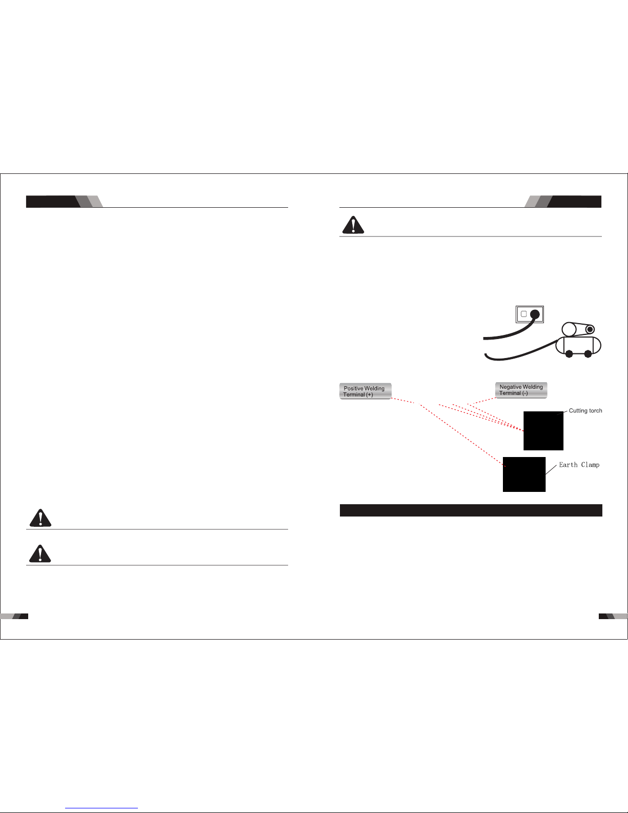
10 910 8
Ope ratio n
Ope ratio n
CA UTI ON
CA UTI ON
CA UTI ON
Do n ot po int the t orc h jet a t for eig n bod ies .
Av oid un ne ce ss ar y li ght in g of the pi lo t ar c to prevent ex ce ss iv e
co ns um pt io n of the el ec tr od e an d no zzl e.
◆Height a bove sea le vel is belo w 100 0m.
◆Operat ion tempe rature ra nge :-10 ˚C~ +40˚ C.
◆Relati ve humidi ty is below 9 0%( 20˚C ).
◆Prefer ably site t he machin e som e angl es ab ove th e flo or lev el, the ma xim um
angle do es not exce ed 15˚.
◆The cont ent of dust ,acid,c orrosiv e gas i n the su rro undi ng ai r or sub sta nce
can not ex ceed norm al standa rd.
◆Take care th at there is s uffi cie nt ven til atio n dur ing we ldi ng.Ther e is at least
30cm fre e disstan ce betwee n the machi ne an d wall .
2.11 Opera tion En viron ment
pow er supp ly
MULTIFUNCTION SERIES EQUIPMENT MULTIFUNCTION SERIES EQUIPMENT
Air c ompre ssor
4. S et you r unit up in an are a whic h is ade quat ely ve ntil ated a nd mak e sure t hat the air
ven ts are n ot obs truc ted.
5. C onne ct the p ower suppl y cable to a sock et loc ated a s near a s poss ible t o the work area,
so th at the u nit ca n be swi tche d off qui ckly i n case o f emer genc y.
6. You r mach ine has a 16 amp pl ug fit ted, b efor e use ch eck th at the green/yellow earth is
con nect ed to th e eart h pin so cket o f fitted plug .
7. M ake su re that the mai ns sup ply sw itch a nd any f uses h ave a va lue wh ich ± 15% t he
max imum c urre nt abs orbe d by the u nit. All fuses shoul d be the s low- blow t ype.
8. An y exte nsio ns of power sup ply ca ble sh ould h ave th e same c ross -sec tion a s the po wer
sup ply ca ble. T he extension leads, how ever, s houl d only b e used w hen ab solu tely
nec essa ry. It is im port ant to n ote th at any e xten sion o f main s cabl es or torch cables wi ll
pos sibl y affe ct the cutting performance of t his cu ttin g equi pmen t, due t o the fa ct tha t the
res ista nce of t he cab le wil l redu ce vol tage input, which is dete rmin ed by th e leng th of th e
cab le. Th e supp lied length of main c able s and to rch ca bles i s reco mmen ded.
9. F aste n the ea rth clamp to th e piec e to be cu t, If th e surf ace of the piece to be cu t is
pai nted , rust y or cov ered w ith in sula ting m ater ial, clean th e surf ace so t hat
sat isfa ctor y cont act be twee n the pi ece an d the earth clamp can b e obta ined .
10. Make s ure th at the t orch h as bee n asse mble d with the corr ect co mpon ents a nd tha t the
cut ting t ip is su itab le for t he cut ting current.
11. Co nnec t air to r egul ator a nd adj ust re gula tor to d eliv er 5-6 bar 90ltr/min
12. Swit ch the u nit on u sing t he mai n swit ch located on the bac k side .
14. Onc e cutt ing is o ver, rel ease th e torch b utton t o put out t he arc. A per iod of po st-fl ow
tim e 45 to 7 5 seco nds (r equ ired f or tor ch co olin g) wil l follo w. Do not di sconn ect air
unt il th is coo ling p eriod h as been c omple ted. Fa ilure t o do this w ill res ult in to rch hea d
dam age.
Dur ing cut ting th e spe ed of th e torc h mov emen t shou ld be i n acco rdan ce wi th the
thi cknes s of the pi ece t o be cut . Exce ssi ve spe ed cau ses a r etur n of inc and esce nt
tow ards th e torch w hic h shor tens t he li fe of th e part s of th e torc h most s ubj ect to
wear and tea r. The metal fo uling on the nozzle sh ould be removed as soo n as possi ble.
13 . Cont act th e cop per t ip of t he to rch t o the w ork p iec e, press the but ton of t he fo rch u nti l
th e cut ting oper atio n.
the ar c-sta rting a nd raise t he cutti ng torc h about 1m m above th e work pie ce, and perform

11 1
11 0
2.12 Oper ation N otice s
MULTIFUNCTION SERIES EQUIPMENT
3.1 Troubleshoo ting
◆Bef ore arc w eldin g machi nes are d ispat ched fr om the fa ctory, t hey ha ve alre ady bee n
deb ugged a ccura tely. So f orbi d anyon e who is no t autho rized b y us to do an y chang e to
the e quipm ent!
◆Mai ntena nce cou rse mus t be oper ated ca reful ly. If any w ire be comes f lexib le or is
mis place d, it may be pote ntial d anger t o user!
◆Onl y profe ssion al main tenan ce pers onal wh o is auth orize d by us cou ld overhau l the
mac hine!
◆Gua rante e to shut o ff the ar c weld ing mac hine’ s power bef ore tu rn on the out line o f
the e quipm ent!
◆If th ere is an y probl em and ha s no the au thori zed pro fessi onal ma inten ance pe rsona l,
ple ase con tact lo cal age nt or the b ranch c ompan y!
If th ere a re som e simp le trou bles of W SME-s eri es wel ding m achin e, you ca n consu lt
the f ollow ing ove rhaul ing cha rt:
Tro ubles hooti ngTro ubles hooti ng
MULTIFUNCTION SERIES EQUIPMENT
◆Read saf ty instru ction and C hap ter 1 ca ref ully b efo re att emp ting t o use t his
equipm ent.
◆Connec t the groun d wire the ma chi ne dir ect ly
◆In case cl osing the p ower swit ch, n o-lo ad vo ltag e may b e expo rte d.Do n ot to uch
the outp ut electr ode with an y part of you r bod y.
◆Before o peratio n,no conc ern ed peo ple s houl d be le ft,D o not w atch t he ar c in
unprot ected eye s.
◆Ensure g ood venti lation of t he ma chin e to im prov e dut y rati o.
◆Tur n off th e engine wh en the oper ati on fin ish ed to ec ono mize e ner gy sou rce .
◆When pow er switch s huts off pr otec tiv ely be cau se of fa ilu re.Don’ t restart i t until
until pr oblem is re solved.
Otherw ise,the r ange of pro blem will b e ext ende d.
Nr.
1
2
4
Troubles
Solution
Fan is broken
The power board is broken
The power cable is broken
There is something in the fan
The start capacitor of fan damaged
Tur n on the p ower
sou rce, po wer
ind icato r is lit, f an
is no t worki ng.
Tur n on the
pow er sour ce,
fan i s worki ng,
pow er indi cator
is no t lit
Tur n on the p ower
sou rce, fa n is not
wor king, p ower
ind icato r is not li t
Reasons
Cha nge fan
Cle an it
Cha nge cap acito r
The p ower li ght dam aged or
con necti on is not g ood
The p ower ca ble con necte d not
goo d
The light of the power indicator is
broken and the problems
mentioned in Nr. 2
Change the light of the power
indicator or refer to the solution
in Nr. 2
Cha nge it
Cha nge it
Cha nge it
Cha nge it
Rep air or ch ange it
Cha nge the p ower li ght
Con nect co rrect ly
Pow er on swi tch is da maged
The p ower bo ard is br oken
Nr.
Troubles
Solution
Reasons
3
6
Tur n on the p ower
sou rce, po wer
ind icato r is lit, f an
is wo rking , there
is no w eldin g
out put.
No no -load
vol tage ou tput
(MM A)
Con trol bo ard is br oken
st
1 in verte r circu it dama ged
nd
2 fee dback c ircui t is faul t
If th e overh eat ind icato r is on
The m ain cir cuit is b roken
The m achin e is brok en
Cha nge it
Rep lace it
Cha nge it
Wait a few minutes, the machine
can b e opera ted nor mal
Che ck and re pair
Con sult th e deale r or the
man ufact urer
Display panel is broken
7
The welding cable is not connected
with the two output if the welder
Connect the welding cable to
the welder's output
The welding cable is damaged
The earth cable connected unstably
The welding cable is too long
Input voltage not stable
There is oil or dust on the workpiece
There is no Argon flow or the
connectio n is poor
The distance between tungsten
electrode and workpiece is too long
Repair or change it
Check the earth cable
Use an appropriate welding cable
Check the power supply
Check and remove it
Reduce the distance
(about 3mm ,less than 5mm)
Check and reconnect
Arc c an not be
ign ited (T IG) ,
the re is spa rk
on th e HF
ign iting b oard
8
The HF igniting board does not work
The distance between discharge r is
too short or too long
The malfunctio n of the welding gun
switch
No argon gas flow or the air tube
connect not good
Repair or change it
Adjust the distance (about 0.8mm)
Check the welding torch switch,
control cable and aero socket.
Check and reconnect
Arc c an not be
ign ited (T IG) ,
the re is no sp ark
on th e HF
ign iting b oard
9
Check if the function selected MMA
Change the function to TIG
Check the HF funtion is selected Select the HF funtion
HF board is broken
Earth clamp connect not stable
Repair or change it
Check the earth clamp
No argon gas flow or the air tube
connect not good
Check and reconnect
Tur n on the
pow er sour ce,
eve rythi ng is
nor mal , but n o
HF ig nitin g
10
Remove it
Change it
Gas a lways f lows
Some thing is in the va lve
Elec tromagn etic valv e is damaged
5
The n umber o f the
dis play is n ot
int act
The d ispla y panel i s damag ed
Cha nge the d ispla y panel
Dig ital tu be is bro ken
Cha nge it

11 3
11 2
Tro ubles hooti ng
MULTIFUNCTION SERIES EQUIPMENT
Nr.
Troubles
Solution
Reasons
13
14
Repair or change it
Change it
Change it
No AC ou tput
whi le sele cting
"AC " for O25 1
The w eldin g
cur rent di splay ed
isn 't acco rdant
wit h the act ual
val ue
Air flo w is not correc tly conne cted
Mach ine is broke n
The pow er board is bro ken
The AC drive boar d damaged
The AC IGBT/IGBT module damaged
The m in valu e displ ayed is n't
acc ordan t with th e actua l value
Adj ust pot entio meter I min on
the c ontro l board
Adj ust pot entio meter I max on
the c ontro l board
The m ax valu e displ ayed is n't
acc ordan t with th e actua l value
17
18
19
Tig torch is connected to the
positive termi nal
Tungsten electrod e is too big for
the welding current
Check the earth clamp position on
the work piece
Check the welding circuit is correct,
for example the earth clamp is
connected to work piece
Connect the tig torch to negative
terminal
Adjust the position of earth clamp
Connect the circuit correctly
Check the air flows
Consult the dealer or the
manufactu rer
Select the correct size of tungsten
electrode
Tig electrode melts
when welding
Arc flutters during
Tig welding
When Cut function
is selected ,there is
HF but cannot cutting
R-S ERIES
MIG SERIES EQUIPMENT
MIG SERIES EQUIPMENT
CHAPTER 6
10
Gas cylinder is close or gas
pressure is low
Something is in the valve
Open or change the gas cylinder
Remove it
Change it
Change it
Pressure too high or air regulator is
broken
Check gas
No ga s flow (T IG)
Elec tromagn etic valv e is damaged
Air tub e is brocken
12
Checking if the electorde stick to
the work piece that the anti-stick
function is on
Repair or change it
The w eldin g
cur rent ca nnot
be ad juste d
Cont rol board is br oken
Shut off the power when changing the tor ch
Sep arate t he elec trode a nd
wor k piece
15
The p enetr ation
of mo lten po ol is
not e nough
Adj ust the d istan ce from t orch
to wo rk piec e
Use t he suit able le ngth fr om
man ufact urer
Inc rease t he weld ing cur rent
The w eldin g curre nt is adj usted
too l ow
The a rc is too l ong in th e weldi ng
pro cess
The p ower ca ble or th e weldi ng
cab le is too l ong
Change to suitable setting AC Width adjustment is not correct
16
Over-heat prot ection ,too much
welding curren t
Reduce the welding current
Reduce the welding time
Over-heat prot ection ,working too
much time
Over-curr ent protection, current in
the main circuit is out of control
Check and repair main circuit
and drive board
Thermal overload
indicator light is on
Check the power supply
Change the fan
Inpu t voltage is to o low
Fan is bro ken
Repair or change it Cont rol board is br oken

11 5
11 4
MIG SERIES EQUIPMENT
R22 1,R23 1,R25 1,R311 MIG w eldin g machin es ado pts th e lates t pulse w idth modulation
(PW M) tech nolog y and ins ulate d gate bi polar t ransi stor (I GBT) po wer mod ule, wh ich can
cha nge wor k frequ ency to m edium f reque ncy so as t o repla ce the tr aditi onal hu lki ng wor k
freq uency trans former with the cab inet medium freq uency trans former. Thus, its charact erized
wit h porta ble, sm all siz e, ligh t weigh t, low co nsump tion an d etc.
1.1 Brief Introd uctio n
◆MCU c ontro l syste m, resp onds im med iate ly to an y cha nges .
◆Hig h frequency and high voltage for arc igniting to ensure the success ratio of igniting arc.
◆Lif t TIG ope rat ion, I f the t ung ste n ele ctr ode t ouc hes t he w ork pie ce whe n welding ,
the c urren t will dr op to s hort -cir cui t curr ent to p rot ect tu ngst en.
◆Sim ple sel ect mater ial/ wire diam eter a nd the s tored kn ow-ho w contr ols the we lding
pro cess au tomat icall y
Sum mary
1.2 Wor king Pr inciple
230 V
The w orki ng prin ciple o f R221/ R231/ R251/ R311 wel ding m achin es is sho wn as the
fol lowin g figur e. Sing le-ph ase 230 V work fr equen cy AC is rec tifie d into DC (ab out 31 2
V), t hen i s conv erte d to medi um freq uency AC ( about 2 0-40K Hz) by in verte r devic e (IGBT
mod ule), a fter re duc ing vo ltag e by medi um tr ansf orme r (th e main t rans for mer) a nd
rec tifyi ng by m ediu m freq uency r ectif ier ( fast r ecov ery d iode s),t hen is ou tputt ed DC .Th e
cir cuit ad opt s curr ent fe edb ack co ntro l tec hnol ogy to i nsu re cur rent o utp ut sta bly.
Mea nwhil e, the we lding c urren t param eter ca n be adju sted co ntinu ously a nd step lessl y to
mee t the req uirem ents of w eld ing cr aft.
◆
occ oure d, the a larm la mp on th e fron t panel will be o n and th e outpu t curr ent wi ll
be cu t off. It can sel f-pr otec t and pr olong the usi ng lif e.
In tel li gen t pr ote cti on: o ver -cu rr ent , ov er- hea t, wh en t he m ent ion ed pr obl ems
R22 1, R231 , R251, R311 MIG m achin es Char acter istic s:
Sum mary
MIG SERIES EQUIPMENT
1.3 Specificat ions R2 21
Due t o varia tions th at can occ ur in manu factu red pro ducts , claime d perfo rmanc e, volta ges,
rat ings, a ll capa citie s, meas ureme nts, d ime nsi ons a nd we igh ts qu oted a re app rox imat e
only. Achievable capacities and ratings in use and operation will depend upon correct installation,
use , appli catio ns, mai ntena nce and s ervic e.
NO TE
Des cript ion
490 X225X 380mm
15. 9kg
Fan C oole d
Mul ti Proc ess Invert er Pow er Sour ce
EN 60 974- 1 / IE C609 74-1
1
230 VAC ± 15%
50/ 60Hz
66V
10- 25 V
2.5 -18
5kg
0.6 /0.8/ 1.0
IP2 3
F
Up to 0. 8mm
80%
0.7 3
25- 200 A
30- 170 A
22. 6 A
35. 7 A
Dim ensio ns
Wei ght
Coo ling
Wel der Typ e
Eur opean S tanda rds
Num ber of Ph ases
Nom inal Su pply Vol tage
Nom inal Su pply Fr equen cy
Ope n Circu it Volta ge
Out put Volt age Ran ge
Wir efeed er Spee d Range
Wir e roll we ight
Wir e roll di amete r
Pro tecti on Clas s
Ins ulati on Clas s
Thi cknes s of mate rial
Eff icie ncy
Pow er Fact or
Wel ding C urren t Range (MIG M ode)
Wel ding C urrent Ran ge (ST ICK Mode)
Eff ecti ve Inpu t Curre nt
Max imum In put Cur rent
Sin gle Pha se Gene rator R equir ement
Dut y cycle , 40°C, 1 0 min(M IG)
R22 1
200A@ 40 %24 V 155 A@ 100%20 .3V
Gas Follow
3s
Dut y cycle , 40°C, 1 0 min(M MA)
170A@ 40 %26 .8V 1 07A@ 100% 24. 2V
12. 3KVA

11 711 6
R22 1
◆3M MB -15 MIG G un – 16M2
◆Con tact ti p•1.0 mm Fitt ed•0. 8mm Fit ted
◆3M Ga s Hose 8* 13.5
◆200 A ele ctrod e holder wit h 3M cab le.
◆200 A ear th clam p with 3M c able
◆3M Po wer cab le
◆Dri ve Roll s
◆Ope ratin g Manua l
1.4 Packa ged Ite ms
1.5 Duty Cy cle
The r ated duty cycle of a Welding Pow er Source is a statemen t of the time it may be operated
at it s rated welding cur rent output with out exceedi ng the tempe ratur e limits of the ins ulati on
of th e compo nent pa rts. To exp lain t he 10 min ute dut y cycle p eriod the following exampl e
is u sed . Sup pos e a Wel din g Pow er So urc e is d esigned t o ope rat e at a 4 0% du ty cycle,
200 a mpere s at 24 vol ts. Thi s mean s that it h as been d esign ed and bu ilt to pr ovide t he
rat ed ampe rage (2 00A) fo r 4 minut es, i.e . arc wel ding ti me, out of ev ery 10 minute per iod
(40 % of 10 min utes is 4 m inute s). Dur ing the o ther 6 mi nutes o f the 10 mi nute pe riod th e
Wel ding P ower So urce mu st idle a nd be allowe d to coo l.
Duty Cyc le (pe rce ntag e)
Safe
Operating
Region
Stick(MMA)
MIG SERIES EQUIPMENTMIG SERIES EQUIPMENT
Weldi ng Current (amps)
1.6 Specificat ions R2 31
NO TE
Due t o varia tions th at can occ ur in manu factu red pro ducts , claime d perfo rmanc e, volta ges,
rat ings, a ll capa citie s, meas ureme nts, d ime nsi ons a nd we igh ts qu oted a re app rox imat e
only. Achievable capacities and ratings in use and operation will depend upon correct installation,
use , appli catio ns, mai ntena nce and s ervic e.
Des cript ion
490 X225X 380mm
16. 2kg
Fan C oole d
Mul ti Proc ess Invert er Pow er Sour ce
EN 60 974- 1 / IE C609 74-1
1
230 VAC ± 15%
50/ 60Hz
66 V
10- 25 V
2.5 -18
5kg
0.6 /0.8/ 1.0
IP2 3
F
Up to 0. 8mm
80%
0.7 3
25- 200 A
30- 170 A
10- 200A
22. 6A
35. 7 A
Dim ensio ns
Wei ght
Coo ling
Wel der Typ e
Eur opean S tanda rds
Num ber of Ph ases
Nom inal Su pply Vol tage
Nom inal Su pply Fr equen cy
Ope n Circu it Volta ge
Out put Volt age Ran ge
Wir efeed er Spee d Range
Wir e roll we ight
Wir e roll di amete r
Pro tecti on Clas s
Ins ulati on Clas s
Thi cknes s of mate rial
Eff icie ncy
Pow er Fact or
Wel ding C urren t Range (MIG M ode)
Wel ding C urrent Ran ge (ST ICK Mode)
Wel ding C urrent Ran ge (TI G Mode)
Eff ecti ve Inpu t Curre nt
Max imum In put Cur rent
R23 1
200A@ 40 %24 V 126 A@ 100%20 .3V
200A@ 40 %18 V 126 A@ 100%15 V
170A@ 40 %26 .8V 1 07A@ 100% 24. 2V
Gas Follow
3s
Dut y cycle , 40°C, 1 0 min(M IG)
Dut y cycle , 40°C, 1 0 min(M MA)
Dut y cycle , 40°C, 1 0 min(T IG)
Sin gle Pha se Gene rator R equir ement
12. 3KVA
Sum mary
Sum mary
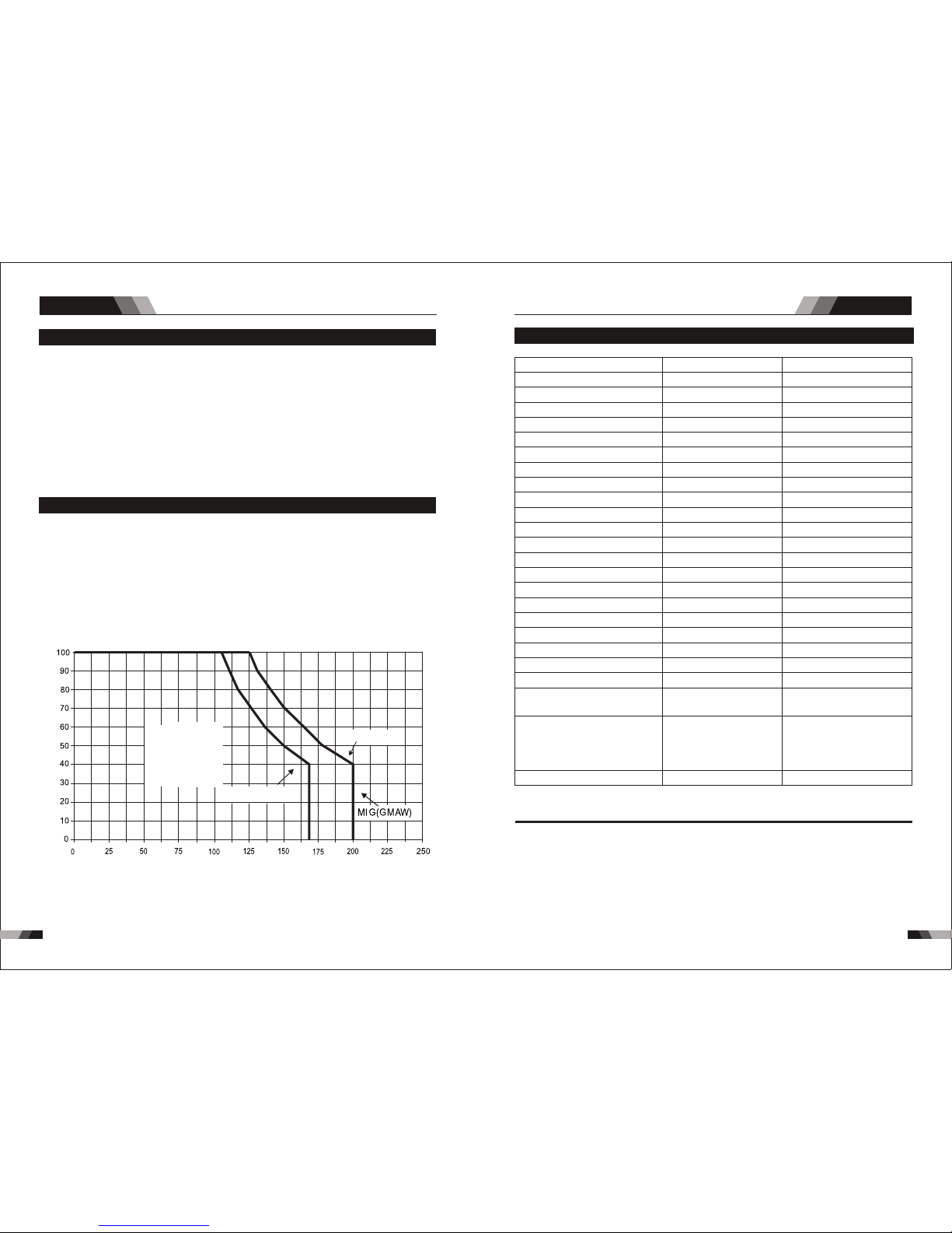
11 91 18
MIG SERIES EQUIPMENTMIG SERIES EQUIPMENT
R23 1
◆3M MB -15 MIG G un – 16M2
◆ Cont act ti p•1 .0mm F itte d0. 8mm Fi tted
◆4M Wp -26 Tig Torc h
◆3M Ga s Hose 8* 13.5
◆200 A ele ctrod e holder wit h 3M cab le.
◆200 A ear th clam p with 3M c able
◆3M Po wer cab le
◆Dri ve Roll s:
◆Ope ratin g Manua l
1.7 Packa ged Ite ms
1.8 Duty Cy cle
The ra ted duty cycle of a Weldi ng Power Sourc e is a statem ent of the time it may be operat ed
at its rate d weld ing current ou tput with out excee ding the te mperature li mits of t he insu latio n
of the compon ent par ts. To expl ain the 10 minute dut y cycl e perio d the foll owing e xampl e is
use d. Su ppos e a Wel ding P owe r Sour ce is d esi gned t o ope rate at a 40% d uty cycle, 200
amp ere s at 24 v olts . This m eans th at it has be en desi gned an d built to p rovid e the rat ed
ampe rage (200A) fo r 4 minute s, i.e. arc weldi ng time, out of ever y 10 min ute per iod (40 % of
10 mi nute s is 4 minut es). D uring the ot her 6 m inu tes of th e 10 minu te period the Wel ding
Pow er Sour ce must id le and be al lowed to cool.
Duty Cyc le (pe rce ntag e)
Safe
Operating
Region
Stick(MMA)
TIG ( GTAW)
Weldi ng Current (amps)
Due t o varia tions t hat can oc cur in ma nufa ctur ed pr oduc ts, cl aimed pe rformance, vol tages ,
rat ings, a ll capac ities , measu remen ts, dime nsions an d weight s quoted are approximate onl y.
Ach ievab le capa citie s and rat ings in u se and ope ration will dep end upon correc t insta llation ,
use , appli catio ns, mai ntena nce and s ervic e.
1.9 Specificat ions R2 51/R311
NO TE
Des cript ion
Dimensions
Weight
Cooling
Welder Type
European Standards
Number of Phases
Nominal Supply Voltage
Nominal Supply Frequency
Open Circuit Voltage
Output Voltage Range
Wirefeeder Speed Range
Wire roll weight
Wire roll diameter
Protection Class
Insulation Class
Thickness of material
Efficiency
Power Factor
Welding Current Range (MIG Mode)
Effective Input Current
Maximum Input Current
R25 1
590x240x450mm
23.6kg
Fan Cooled
Single Function
EN 60974-1 / IEC60974-1
3
400VAC ± 15%
50/60Hz
66 V
13-30 V
1.4-18
5-15kg
0.8/1.0
IP23
F
Up to 0.8mm
85%
0.93
30-250 A
9.3 A
12.1 A
590x240x450mm
24.8kg
Fan Cooled
Single Function
EN 60974-1 / IEC60974-1
3
400VAC ± 15%
50/60Hz
66 V
13-30 V
1.4-18
5-15kg
0.8/1.0
IP23
F
Up to 0.8mm
85%
0.93
30-300 A
8.7 A
15.9 A
R311
5s
3s
Gas Follow
250A@ 60%26.5V
193A@ 100%23.6V
Duty cycle, 40°C, 10 min.
300A@ 30%29V
232A@ 60%25.6V
164A@ 100%22.2V
Sin gle Pha se Gene rator
Req uirem ent
12. 6KVA 16. 5KVA
Sum mary Su mmary

12 11 20
Sum mary
MIG SERIES EQUIPMENTMIG SERIES EQUIPMENT
R25 1/R311
◆4M MB -24 MIG G un – 25M2
◆Con tact ti p •1.0m m Fitte d 0.8mm F itt ed
◆3M Ga s Hose 8* 13.5
◆300 A ear th clam p with 3M c able
◆3M Po wer cab le
◆Dri ve Roll s
◆Ope ratin g Manua l
1.10 Pack aged It ems
1.11 Duty Cy cle
The rated duty cyc le of a Weldi ng Power Source is a statement of the time it may be operated
at its rated we lding curre nt output without exceeding the temperature limi ts of the insulation of
the component parts. To explain the 10 minute duty cycle period the following example is used.
Suppo se a Weldi ng Power Source is designed to operate at a 30% duty cycle, 300 amperes at
29 volts. This means that it has been designed and built to provide the rated amperage (300 A)
for 3 minutes, i.e. arc welding time, out of every 10 minute period (30% of 10 minutes is 3 minutes).
Durin g the other 7 minutes of the 10 minute period the Welding Power Source must idle and be
allow ed to cool.
300
Duty Cyc le (pe rce ntag e)
Safe
Operating
Region
MIG(R251)
MIG(R311)
Weldi ng Current (amps)
2.1 Layout For The P anel R2 21
1. Power I ndi cat or
The g reen p ower i ndic ator will be il lumi nate d when the welder is tu rned O N and indi cate s
the p rese nce of p ower.
3. JOB and S AVE
You ca n pres s JOB to se lect the memory re cords t hat yo u have s aved bef ore from 1-9 .
For t he new s etti ng of p rese nt bas e cur rent Am ps ,ju st pr ess SAV E.
4. Digit al Ammete r
The d igital meter is use d to display th e pre-set (pr evie w) ampe rage i n STICK / M ig modes
and a ctua l weldi ng amp erage o f the power sou rce wh en weld ing, i t is also u sed to
dis play p arame ters f rom sel ecti ng fun ction b utto n 6.
4 5
3
11
2
1
10
6
12
14
13
9
8
7
DO NO T TOU CH the e lectr ode wire whi le it is bein g fed thro ugh the sy stem. The ele ctro de
wir e will be a t weldi ng volt age potent ial.
WAR NIN G
2. Therm al Ov erl oad Indic ato r Lig ht
Thi s weld ing pow er sour ce is pro tecte d by a self r esett ing the rmost at. The i ndic ator wi ll
illumi nat e if the d uty c ycle o f the p ower s ourc e has be en ex ceed ed. S houl d the th erma l
ov erl oad indic ator i llu min ate t he output o f the po wer s our ce wi ll be d isa ble d. Once the
po wer s our ce cools down th is lig ht wi ll go O FF an d the o ver t emp era tur e con diti on wil l
au tomatic all y res et. N ote th at the m ain s pow er sw itch s houl d rem ain i n the o n posi tion
su ch that the f an con tin ues t o oper ate th us al low ing th e unit t o coo l suff icie ntl y. Do not
swi tch the u nit off s houl d a therm al over load co nditi on be pre sent.
Ope ratio n
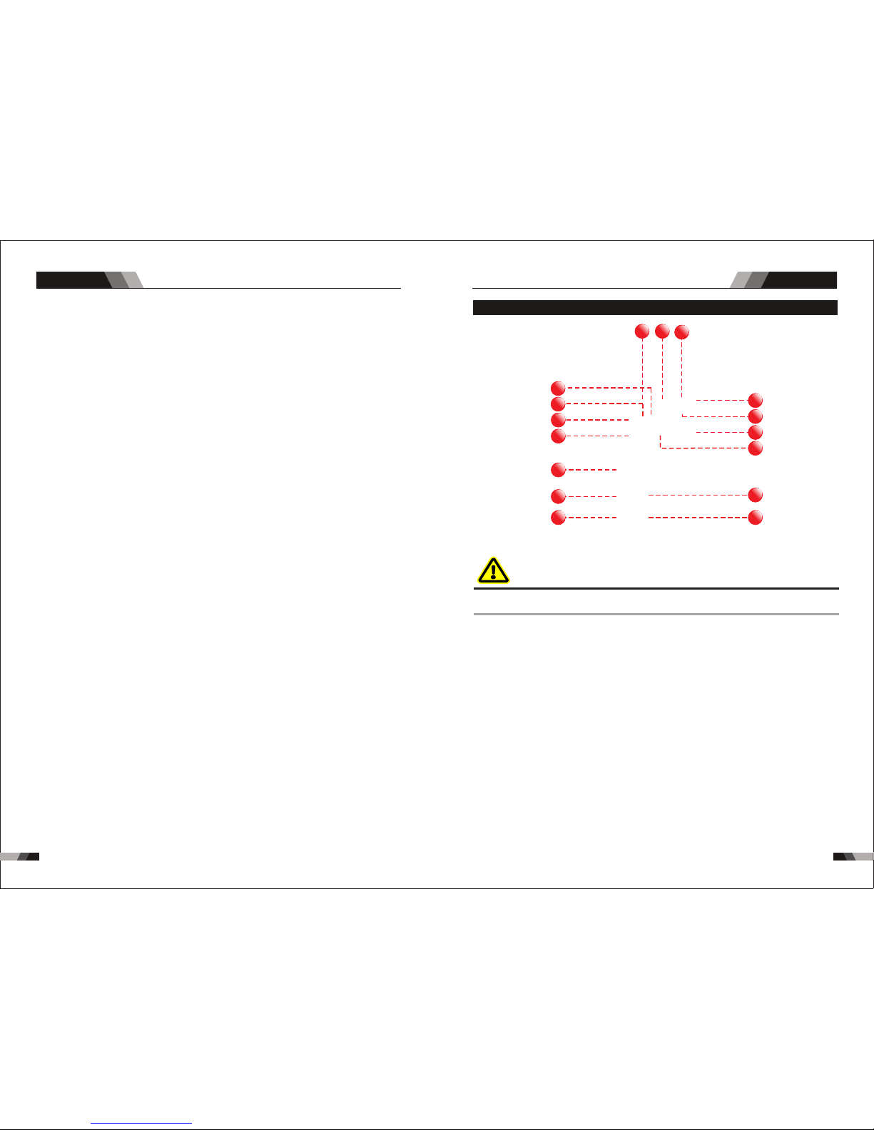
12 31 22
MIG SERIES EQUIPMENT
Ope ratio n
Ope ratio n
MIG SERIES EQUIPMENT
5. Digit al Vol tmeter
The d igita l meter i s used to d isp lay the pr e-se t (prev iew ) Voltage i n Mig modes a nd
act ual welding Volta ge of the powe r source whe n weldi ng. This di gital me ter is use d to
dis play the We lding O utput Ter mina l Voltage in ST ICK mo des durin g non- w elding or
wel ding.
7. Posit ive C ont rol
The p ositi ve cont rol is us ed to plu s selec ted fun ction f rom 6.
8. Negat ive C ont rol
The n egati ve cont rol is us ed to min us sele cted fu nctio n from 6.
9. We ld Pr oce ss Select ion B utton
Pre ss and r elease th is but ton to c hang e the selec ted weld process mode from mig to
tig to stick. Th e weld p roce ss wil l cha nge t o the n ext p roce ss in th e sequ ence e ach time
the b utto n is presse d and re leas ed. The gree n indicators nex t to th e butt on wi ll
ill uminate t o iden tify m ig to ti g to sti ck pro cess m ode.
10. 2T - 4T Tri gge r Lat ch Button
Pres s and release the button to change the selected operating mode of the trigger. The
selected mode can be either “2T” (u nlatc hed) or “4T” (l atched) operat ion. The gre en
indic ator next to the b utto n will i llum inat e to iden tify which mode is sel ected (2T or 4T).
In th e 4T mod e once t he wel d has be en sta rted y ou can r elea se the t rigg er and
con tinu e weld ing un til th e trigger is activate d agai n or the weldi ng arc is broken to stop
the w eldi ng arc .
11. 0.6/0 .8/ 1.0 /SPL
Pre ss this b utton t o choos e the wel ding ma teria ls diam eter, SP L is st ainl ess ste el.
12. MIG Tor ch Co nnectin g
The M IG Torc h Ada pter i s the conne ctio n point for t he MIG Tor ch. Pr ess the MIG Torch
in an d secur e by turn ing the l ockin g ring to t he righ t (cloc kwise )
13. Nega tiv e Welding O utp ut Term ina l
to th e appr opri ate we lding acc esso ry suc h as the e arth c lamp ( for Mig fun ctio n) or
ele ctrode ho lder ( for St ick fu ncti on). Nega tive w eldi ng cur rent s hows to th e pow er
sou rce via this heavy duty bayone t type termi nal. It is essenti al, however, that the male
plug is inserted and turn ed sec urel y to ach ieve a s ound elec tric al con nect ion.
14. Posi tiv e Welding O utp ut Term ina l
to t he ap pro pri ate w eld ing a cce sso ry su ch as t he MI G Gun ( via t he MIG G un pol arit y
lea d) or g rou nd cl amp ( for St ick f unc tio n). P osi tiv e wel din g cur ren t flo ws fro m the
mal e plug i s inser ted a nd tu rne d sec ure ly to a chi eve a s oun d ele ctr ica l con nec tio n.
6. Selec tin g fun ction But ton
Pre ss and releas e this b utton to cha nge t he se lec ted w eld fu ncti ons mode from w eldi ng
cur rent t o induc tanc e to Volt to B urnb ack .
The ne gativ e weldi ng termi nal is used to conn ect the we lding output of the power s ource
The p ositi ve weld ing ter mina l is used to conne ct the welding o utput o f the pow er sour ce
powe r source v ia this he avy duty b ayonet t ype term inal. It is essent ial, ho wever, that the
2.2 Layout For The P anel R2 31
44 55
33
1111
1515
1616
22
11
1010
66
1212
1414
1313
99
88
77
DO NO T TOU CH the e lectrod e wire w hile it is be ing fe d through t he sys tem. The electr ode
wir e will be a t weldi ng volt age potent ial.
WAR NIN G
1. Power I ndi cat or
The g reen p ower indicator wi ll be il lumi nate d when the we lder is turned ON and indi cate s
the p rese nce of p ower.
3. JOB and S AVE
You ca n pres s JOB to se lect the memory re cords t hat yo u have s aved bef ore from 1-9 .
For t he new s etti ng of p rese nt bas e cur rent Am ps ,ju st pr ess SAV E.
2. Therm al Ov erl oad Indic ato r Lig ht
Thi s weld ing pow er sour ce is pro tecte d by a self r esett ing the rmost at. The i ndic ator wi ll
illumi nat e if the d uty c ycle o f the p ower s ourc e has be en ex ceed ed. S houl d the th erma l
ov erl oad indic ator i llu min ate t he output o f the po wer s our ce wi ll be d isa ble d. Once the
po wer s our ce cools down th is lig ht wi ll go O FF an d the o ver t emp era tur e con diti on wil l
au tomatic all y res et. N ote th at the m ain s pow er sw itch s houl d rem ain i n the o n posi tion
su ch that the f an con tin ues t o oper ate th us al low ing th e unit t o coo l suff icie ntl y. Do not
swi tch the u nit off s houl d a therm al over load co nditi on be pre sent.
4. Digit al Ammete r
The d igital meter is use d to display the pr e-set (p revi ew) am pera ge in ST ICK / Mi g modes
and a ctua l weld ing am pera ge of th e power sourc e when w eldi ng, it i s also u sed to
dis play p aram eter s from s elec ting f unct ion bu tton 6.

12 5
12 4
The po larity lead is used to conne ct the MIG Gun to the approp riate posit ive or negative out put
ter minal (allow ing polarity re versal for differen t welding appl ication s). In general, the pol arity
lea d should be conne cted in to the posi tive weldi ng ter minal (+) wh en usin g steel , stain less
steel or aluminum electrode wire. When using gasless wire, the polarity lead is generally connected
to the n egati ve weld ing ter minal ( -). If in doubt, consult the ma nufactur er of the electrode wire
for th e correct polarity. It is essential, however, that the male plug is inserted an d turned securely
to ach ieve a so und ele ctric al conn ectio n.
2.3 MIG Gun Polari ty Lead
15. Remo te Co ntr ol Switch
Rem ote Contr ol Swi tch r ecep tacle is used t o conn ect a tr igge r swit ch or rem ote
con trol t o the we ldin g Power Sourc e circ uitr y:
To make connectio ns, align ke yway, insert plug, and rota te thread ed collar fu lly clock wise.
The s ocke t infor matio n is incl uded in t he even t the sup plied c able is n ot suit able an d it
is ne cessa ry to wir e a plu g or cab le to in terfa ce with t he re cept acle .
16. Shie ldi ng Ga s Outlet
Th e Shi eld ing G as Ou tle t loc ate d on th e fro nt pa nel i s a fas t conn ecti on of a s uita ble
TIG Tor ch.
Ope ratio n
MIG SERIES EQUIPMENTMIG SERIES EQUIPMENT
5. Digit al Vol tmeter
The d igita l meter i s used to d isp lay the pr e-se t (prev iew ) Voltage i n Mig modes a nd
act ual welding Volta ge of the powe r source whe n welding. This di gital me ter is use d to
dis play the We lding O utput Ter mina l Voltage in ST ICK mo des durin g non- w elding or
wel ding.
7. Posit ive C ont rol
The p ositi ve cont rol is us ed to plu s selec ted fun ction f rom 6.
8. Negat ive C ont rol
The n egati ve cont rol is us ed to min us sele cted fu nctio n from 6.
11. 0.6/0 .8/ 1.0 /SPL
Pre ss this b utton t o choos e the wel ding ma teria ls diam eter, SP L is st ainl ess ste el.
14. Posi tiv e Welding O utp ut Term ina l
The positi ve welding terminal is u sed to co nnect the weldi ng outp ut of the power sou rce
to the a pprop riate w eldin g acces sory su ch as the MI G Gun (vi a the MIG Gu n polarity
lead) o r groun d clamp (f or Stic k funct ion). P ositi ve weld ing cur rent fl ows from the
power sou rce via this heavy du ty bayone t type termina l. It is essentia l, however, that the
male plug is ins erted and turned secure ly to ach ieve a sound elec trical connectio n.
6. Selec tin g fun ction But ton
Pre ss and r elea se thi s butt on to ch ange t he se lect ed we ld fun ctio ns mod e from w eldi ng
cur rent t o indu ctan ce to Vol t to Bur nbac k .
10. 2T - 4T Tri gge r Lat ch Button
Pres s and releas e the button to change the select ed operating mode of the trigger. The
selected mode ca n be either “2 T” (unl atche d) or “4T” (la tched ) operat ion. The gr een
indic ator next to th e butt on wi ll ill umin ate t o identify whic h mode is sel ected (2T or 4T).
In th e 4T mode o nce th e weld ha s been st arted y ou ca n rele ase th e trigg er and
con tinue w eldin g until t he trig ger is ac tivat ed agai n or the we lding arc is b roke n to stop
the w eldin g arc.
12. MIG Tor ch Co nnectin g
The M IG Torc h Ada pter i s the conne ctio n point for t he MIG Tor ch. Pr ess the MIG Torch
in an d secur e by turn ing the l ockin g ring to t he righ t (cloc kwise )
13. Nega tiv e Welding O utp ut Term ina l
The n egati ve weld ing te rmina l is used t o conne ct the wel ding outpu t of the powe r source
to the a pprop riate weldi ng acce ssory such as th e earth clamp (for Mig functi on) or
ele ctrod e holde r (for St ick fu nctio n). Neg ativ e weldi ng curr ent sh ows t o the p ower
sou rce via this heavy duty bayonet type terminal. It is essential , however, that the male
plug is inserted and turned s ecure ly to ach ieve a so und electri cal con nect ion.
9. We ld Pr oce ss Select ion B utton
Pre ss and re lease t his but ton to ch ang e the selec ted weld process mode from mig to
tig to stick. T he wel d proc ess w ill ch ange to th e ne xt pro cess in t he sequ ence ea ch time
the b utton i s press ed and re lease d. The gr een i ndi cat ors n ext t o the bu tto n wil l
ill umina te to ide ntify m ig to tig t o stick p roces s mode.
Ope ratio n
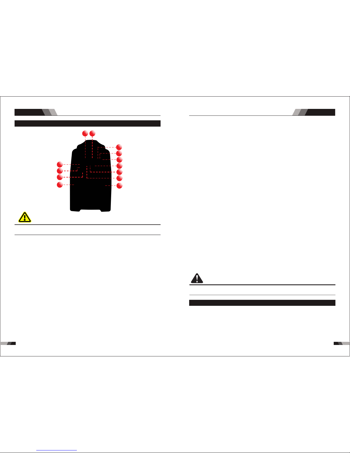
12 712 6
2.4 Layout For The P anel R3 11
2. Wo rk In dic ator
The i ndica tor sho ws the ma chine i s in work ing sui tatio n.
4. Digit al Ammete r
The dig ital meter is used to display inductan ce in Mig modes and actual welding amperage
of the power sourc e when weldi ng.
Ope ratio n
MIG SERIES EQUIPMENTMIG SERIES EQUIPMENT
6
10
11
12
4 54
3
8
7
9
13
2
1
1. Power I ndi cat or
The g reen p ower indicator will be il lumi nate d when the we lder is tu rned O N and in dica tes
the p rese nce of p ower.
DO NO T TOUCH t he ele ctro de wire while i t is bei ng fed t hrou gh the system . The el ectr ode
wir e will b e at wel ding v olta ge potentia l.
WAR NIN G
5. Digit al Vol tmeter
The d igita l meter i s used to d ispla y the pre- set (p rev iew) Vol tage and bur n back in Mig
mode s and actu al weld ing Volta ge of the pow er sour ce when welding . Thi s digita l meter is
used to di splay the We ldi ng Out put Term inal Vo lta ge in ST ICK mo des d urin g non wel ding or w eldin g.
Thi s weld ing pow er sour ce is pro tecte d by a self r esett ing the rmost at. The i ndic ator wi ll
3. Therm al Ov erl oad Indic ato r Lig ht
illumi nat e if the d uty c ycle o f the p ower s ourc e has be en ex ceed ed. S houl d the th erma l
ov erl oad indic ator i llu min ate t he output o f the po wer s our ce wi ll be d isa ble d. Once the
po wer s our ce cools down th is lig ht wi ll go O FF an d the o ver t emp era tur e con diti on wil l
au tomatic all y res et. N ote th at the m ain s pow er sw itch s houl d rem ain i n the o n posi tion
su ch that the f an con tin ues t o oper ate th us al low ing th e unit t o coo l suff icie ntl y. Do not
swi tch the u nit off s houl d a therm al over load co nditi on be pre sent.
7. Selec tin g fun ction But ton
Pre ss and rel eas e th is bu tton to c han ge th e sel ect ed w eld f unct ions m ode f rom
wel ding cu rrent t o induc tance i n left di splay o r from Vol t to Burn bac k from t he rig ht
dig ital di splay.
8. Posit ive C ont rol
The p ositi ve cont rol is us ed to plu s selec ted fun ction f rom 7.
9. Negat ive C ont rol
The n egati ve cont rol is us ed to min us sele cted fu nctio n from 7.
omp onent s are at Ma ins vol tage po tenti al.
10. Gas ch eck ing
Pr ess t his but ton t o ch eck t he flow o f the gas , repr ess t he but ton w ill ca use th e clo se
the f low of ga s.
11. Wire ch eck ing
Pre ss this b utton t o check t he wi res co ming f rom the w eldin g rolls
12. MIG Tor ch Co nnectin g
The MI G Torch Adap ter is the co nnecti on point for the MIG Torch. Pr ess the MI G Torch in
and se cure by tur ning the l ocking r ing to the right (clockwise )
13. Nega tiv e Welding O utp ut Term ina l
The n egati ve weld ing ter minal i s used to c onnect the weld ing out put of t he pow er
sou rce to the a ppro pri ate we ldin g acc esso ry suc h as th e eart h clam p. Ne gat ive
we ldi ng cu rren t show s to the p ower sour ce via t his heavy duty bayonet type termina l.
It is essential , howev er, that the male plug is inser ted and t urned sec urel y to achiev e a
sou nd elec trica l conne ction .
CA UTI ON
Loo se welding term inal connections can ca use ove rheat ing and resul t in the ma le plug bei ng
fus ed in the b ayone t termi nal.
2.5 Installing a 5 kg Spool 200mm Diameter (For R221,R231)
In or der to i nstall a 5 k g / 200 mm di amet er spo ol, assemb le the wi re into t he spoo l hub and
rep lace th e wire sp ool hub c over.
Ins talla tion o f wire spool.
1. Re move Wi re Spoo l hub cov er.
2. Pl ace Wir e Spool o nto the h ub, put b ack the h ub cove r back, tu rn securel y to keep th e wire
spool stab le on the hu b.
6. 2T - 4T Trig ger L atc h Button
Pres s and releas e the button to change the select ed operating mode of the trigger. The
selected mode can be ei ther “2T ” (unlat ched) or “4 T” (latched) op erati on. The red
indic ator next to th e butt on wi ll ill umin ate t o identify whic h mode is sel ected (2T or 4T).
In th e 4T mode o nce th e weld ha s been st arted y ou ca n rele ase th e trigg er and
con tinue w eldin g until t he trig ger is ac tivat ed agai n or the we lding arc is b roke n to stop
the w eldin g arc.
Ope ratio n
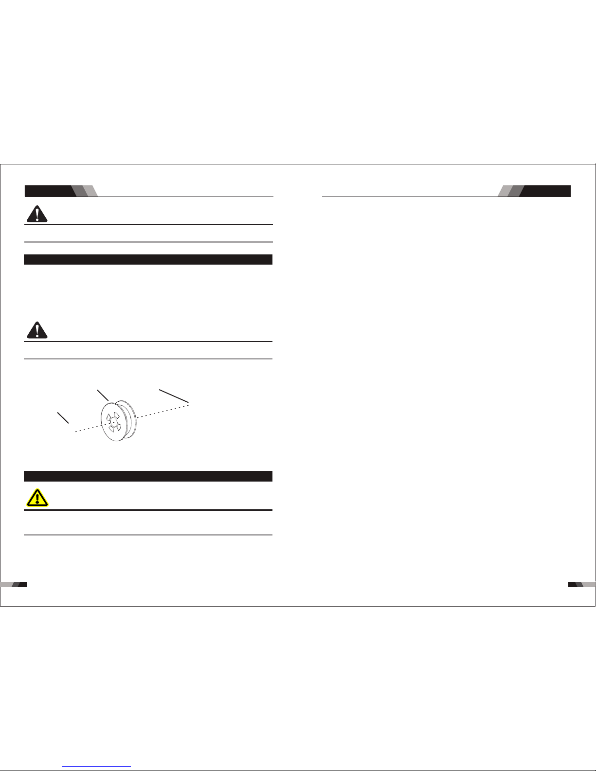
12 912 8
2.6 Installing a 15 kg Spool 300mm Diameter (Suitable For R251 And R311)
In order to t a 15 kg / 300mm diameter spool, assemble the wire into the spool hub and replace
the wire sp ool hub cover.
Insta llation of wir e spool.
1. Remove Wire Spool hub cov er.
2. Plac e Wire Spool onto the hub, put back the hub cover back, turn securely to keep the wire
spool st able on the hub.
CA UTI ON
Use c are in ha ndlin g the spo oled wi re as it wi ll tend t o “unra vel” wh en loosene d from t he
spo ol. Gra sp the en d of the wi re firm ly and do n’t let g o of it.
1. Lo osen th e Sprin g Press ure Adju sting K nob if ne eded an d swing it dow n (See p art 1) .
2. Mo ve the Pr essur e (top) R oller Ar m by swin ging it t o the rig ht. (Se e part 2) .
3. Ma ke sure t he end of t he wi re i s fr ee o f an y bu rr s and is s traig ht. Pas s the end o f wire
thr ough th e Inlet W ire G uide a nd ove r the Fee d roll. M ake ce rta in th e pro per g roov e is
bei ng used .(See p art 2) .
2.7 Inserting Wire Into The Feed Mechanism
WAR NIN G
ELE CTRIC SHOCK CAN KIL L! Make certain the inp ut power is disconne cted from the power
so urc e bef ore pro cee din g. DO N OT rea ttac h the i nput p ower u nti l told t o do so in t hes e
ins truct ions.
Ope ratio n Ope ratio n
MIG SERIES EQUIPMENTMIG SERIES EQUIPMENT
Wel ding w ire
Loc ating p in
dis c shaft
CA UTI ON
Use ca re in hand ling th e spoole d wire as it will tend to “u nrave l” when loosened from the spool.
Gra sp the en d of the wi re firm ly and do n’t let g o of it.
7. Us e the Spr ing Pressure Adjusting Knob to create a “snug” cond ition. (Clockwise to Tighten
a nd Coun ter Clo ckwis e to loos en).
8. La st pict ure sho ws the re sult wi th wire i nstal led. Co ntinu e to the next sect ion fo r prop er
set ting of t ens ion.
5. Cl ose the P ressu re Roll er Arm.
6. Sw ing the S pring P ressu re Adjus ting Kn ob back i nto pla ce.
4. Pa ss the MI G wir e over t he dri ve ro ll gro ove, t hroug h the out let gui de and ou t past th e
MIG Tor ch Ada ptor. T hen fi t the M IG Torch t o ens ure th e MIG wi re pa sses i nto th e MIG
Torch line r of the M IG Torc h.
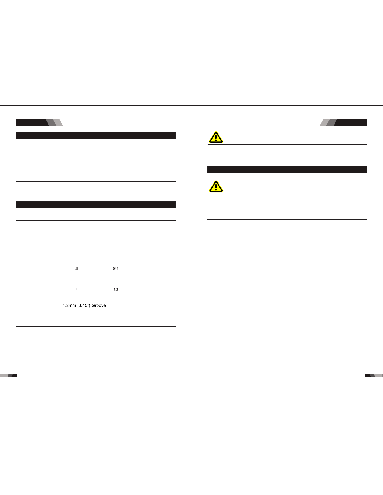
13 113 0
2.8 Feed Roller Pr essur e Adj ustme nt
The r oller o n the swi ng arm ap plies p ressu re to the g roove d rolle r via an adju stable tension
dev ise. The Tension Adjust er should be set to a minimum pressure tha t will provide satisfactory
wir e feed wi thout s lippa ge. If sl ippin g occur s, and in spec tion o f the wire o ut of th e MIG Gu n
rev eals no d efor mati on or w ear, th e con dui t lin er sh oul d be ch ecke d for kinks o r clog ging
fro m metal f lakes . If this i s not th e cause of sl ippin g, the fee d roll pre ssure c an be increased
by ro tatin g the Tensi on Adjusti ng kno b clockwise. The use of exces sive pres sure may caus e
rap id wear o f the fee d rolle r, motor s haft an d motor b earin gs.
Gen uine co ntact t ips and l iners s hould b e used. M any non -genu ine liners u se inf erior
mat erial s which c an caus e wire fe ed prob lems.
2.9 Changing The F eed Rol l
Feed rolls often come with a rust prohibitive coating that needs to be cleaned off before installation .
A Feed r oll con sists o f four d iffe rent siz ed gr oove s. As delive red fr om the fact ory th e drive
rol l is inst alled f or 0.6 / 0. 8 mm .
The s ize tha t is visi ble whe n fitti ng the fe edrol l is the gr oove si ze in use .
All g roove d feed ro lls hav e their w ire siz e or rang e stamp ed on the s ide of th e roll. O n rolls
wit h diffe rent s ize gr oov es, t he ou ter ( visi ble wh en ins tal led) s tamp ed wi re siz e indi cat es
the g roove i n use.
Ref er to fee d roll ki t in the App endix f or the pr oper se lecti on and or derin g of feed r oll kit s.
Kit i nclud es driv e rolls , an inpu t wire gu ide and a n outpu t wire gu ide for a spe cific wi re type
and s ize.
Fee d rolls a re remo ved by tw istin g the fee d roll re taine r cap and ali gning the re taining kno b
spl ines/ tabs wi th the dr ive gea r splin es. Feed r olls are instal led by putting the fe ed roll o nto
the d rive gea r spl ines and t wist ing t he fe ed r oll r eta ine r ca p so that t he sp line s/ta bs re st
aga inst th e face of t he feed r oll whe re they w ill cli ck into p lace.
NO TE
NO TE
NO TE
Ope ratio n O perat ion
MIG SERIES EQUIPMENTMIG SERIES EQUIPMENT
The s tampe d marki ng on the f eed rol l refer s to the gr oove fu rthes t from th e sta mped m arki ng.
Whe n mount ed, tha t will be t he groo ve clos est to th e motor a nd th e one to t hrea d.
To ensu re prop er wire f eed, th e groov e close st to the m otor mu st matc h the ele ctrod e wire
siz e being u sed.
WAR NIN G
The w eldin g wire is ele ctrically Ho t if it is fed by depressi ng MIG Gun switch. Electrode contac t
to wo rk piec e will ca use an ar c with MI G Gun swi tch dep resse d.
2.10 Shielding G as Regu lator Operating Instr uctio ns
WAR NIN G
Thi s equip ment is d esign ed for us e with we lding g rade (I nert) s hield ing gases on ly.
Sh iel din g Ga s is n ot re qui red if th e unit is u sed w ith s elf s hie lde d FCA W (fl ux c ore d arc
wel ding) w ires
Shi eldin g Gas R egul ator S afe ty
Gas regulato rs are design ed to reduc e and control high pressur e gas from a cylinder or pipe line
to th e worki ng pres sure re quire d for the e quipm ent usi ng it. If t he equi pment i s impro perly
used , haza rdous conditions are crea ted that m ay cause accidents. It is the users responsibility
to pr event such cond ition s. Bef ore ha nding or us ing th e equipm ent, underst and and comply
at al l times w ith the s afe pra ctice s presc ribed i n the man ufact urer' s instr uct ions .
SPE CIFIC P ROCED URES fo r the use o f reg ulat ors ar e liste d below.
1. NE VER sub ject th e regul ator to i nlet pr essur e great er than i ts rate d inlet p ressu re.
2. NE VER pr ess uri ze a r egu lat or th at ha s loo se o r dam age d pa rts o r is i n a que stionab le
con ditio n. NEVE R loose n a con necti on or att empt to rem ove an y part of a reg ulat or until
the gas pressure has been reli eved. Under pre ssure, gas can dangerously prop el a loose par t.
3. Do N OT remo ve the r egula tor fr om a cy lin der wit hou t fir st cl osin g the c ylin der va lve a nd
rel easin g gas in th e regul ator hi gh and lo w press ure cha mbers .
4. Do N OT use th e regu lator a s a contr ol valv e. When d ownst ream eq uipme nt is not i n use
for e xtend ed peri ods of ti me, shu t OFF t he gas a t the cy lin der va lve an d relea se the ga s
fro m the equ ipmen t.
5. OP EN the cy linde r valve S LOWLY. Clo se aft er use .
User Respo nsi bil iti es
This equ ipment will per form safely and re liabl e only whe n instal led, op erate d and main taine d,
and rep air ed in acc ord anc e with th e instruct ion s pro vid ed. Equ ipm ent m ust be ch ecked
per iodic ally an d repai red, re placed, or r eset a s nec ess ary f or con tinu ed sa fe and r elia ble
pe rfo rma nce . De fec tive e qui pme nt shou ld no t be u sed . Parts t hat a re bro ken, mis sin g,
obv iousl y worn, d istor ted, or c ontam inate d shoul d be repl aced im media tely.
The u ser of th is equi pment w ill ge ner all y ha ve the sole r espo nsibili ty for a ny malfun ctio n,
whi ch res ults fro m imp rop er us e, fa ult y mai nten anc e, or b y repai r by an yone oth er th an
an ac credi ted rep airer.
NO TE
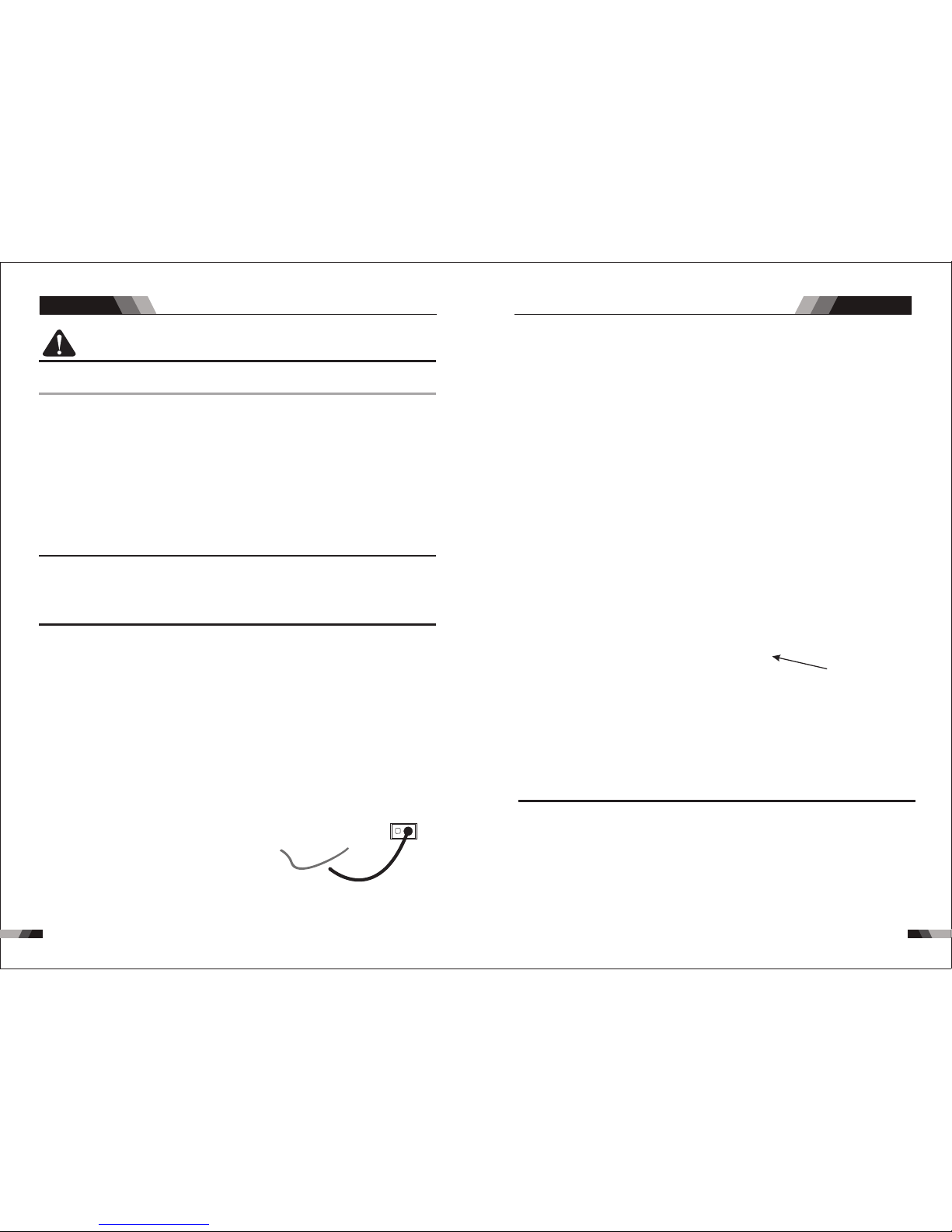
13 313 2 13 313 2
Match regu lat or to c yli nde r. NEV ER CO NNECT a re gul ato r des igned for
a particul ar ga s or ga ses t o a cyl ind er co ntaining any other gas.
The r egula tor/ ow m eters u sed wit h argon b ased an d carbo n dioxi de shie lding gase s are
dif fere nt. A suit ab le regu lator/ ow me ter wi ll need to be f itte d.
All v alves d ownst ream of t he regul ator mu st be open ed to obtai n a true o w rate r eading on
the outl et gauge. (Welding power source must be triggered) Close the valves after the pre ssure
has b een set .
Ins talla tion
1. Re move cyl inder valve pla stic dust seal. Cl ean the cy linde r valve ou tlet of impu riti es that
may c log ori fices a nd dam age sea ts be for e co nne cti ng th e reg ula tor. Cra ck th e valv e
(open then close) momen tarily, pointi ng the outlet away from peo ple and sources of igni tion.
Wip e with a cl ean lin t free cl oth.
2. Ma tch regulator to cylinde r. Before con necti ng, che ck that the reg ulato r label an d cylinder
mar king ag ree and t hat the r egulator inl et and cyl inder ou tlet ma tch. NEV ER CONNECT
a reg ulato r design ed for a part icular gas or gas es to a cyli nder cont aini ng any othe r gas.
3. Co nnec t the r egul ator inl et co nne ctio n to cy lind er or pi pel ine an d Tight en it f irml y but
not e xcess ively, w ith a su itabl e spann er.
4. Att ach sup plied g as line b etwee n the reg ulato r outpu t and the d esire d input a t the rea r
of th e power s ource .
CA UTI ON
Ens ure that the gas cyl inder is
secure d to a building pillar, wall
bra cket or ot herwi se secu rely
fix ed in an up right p ositi on.
NO TE
NO TE
Ope ratio n
Ope ratio n
powe r suppl y
MIG SERIES EQUIPMENTMIG SERIES EQUIPMENT
5. To prot ect sen sitiv e down-s tream equ ipmen t a sep arate s afe ty dev ice ma y be ne cess ary
if th e reg ulat or is no t fitte d with a pr ess ure re lief d evice .
Ope ratio n
Wit h the re gul ato r co nne cte d to c yli nde r or p ipe lin e, and t he adjust ment s crew/kn ob ful ly
dis engag ed, pre ssuri ze as fol lows:
1. St and t o one sid e of r egu lat or an d slo wly o pen the c yli nde r val ve. If ope ned quickl y, a
sud den pre ssure s urge ma y damag e inter nal reg ulato r parts .
2. Wi th valv es on dow nstre am equi pment c losed , adjus t regul ator to a pprox imate w orkin g
pre ssure . It is rec omm ende d that t est ing fo r leak s at th e reg ulat or conn ectio n points b e
car ried ou t using a s uitab le leak d etect ion sol ution o r soapy w ater.
3. Pu rge air o r other u nwant ed weld ing gr ade s hie ldi ng ga s from equi pmen t connect ed to
the r egula tor by ind ividu ally opening th en closing the equ ipmen t contr ol valve s. Complet e
pur ging ma y take up t o ten sec onds or m ore, d epe ndi ng up on th e leng th and s ize o f the
hos e being p urged .
Adj ustin g Flow Ra te
Wit h the reg ulato r ready f or oper ation , adjus t worki ng ow rat e as foll ows:
1. Sl owly tu rn adju sting s crew/ knob in ( clock wise) d irect ion unti l the outl et gaug e indica tes
the r equir ed ow rat e.
It ma y be nece ssary t o re-ch eck the s hie ldin g gas re gulat or ow rat e followin g the fi rst we ld
seq uence d ue to bac k press ure pre sent wi thin sh ieldi ng gas hose as semb ly.
2. To red uce ow r ate, al low the w eldin g grade shie ldin g gas to disc harg e from regu lato r by
ope ning th e down- s tream v alve. B leed we lding g rade sh ieldi ng gas int o a wel l ventil ated
are a and awa y from an y ignit ion sou rce. Tur n adjus ting sc rew coun tercl ockwi se, until the
req uired o w rate is i ndica ted on th e gauge . Close d ownst ream va lve.
3. Adj ust reg ulato r pressu re adju sting sc rew to the re quired ow rate, indica ted on gauge dial.
The ga s ow rate shou ld be adequate to cover the weld zone to stop weld por osity. Exce ssive
gas o w rates m ay caus e turbu lence a nd weld p orosi ty.
NO TE
Screw kn ob
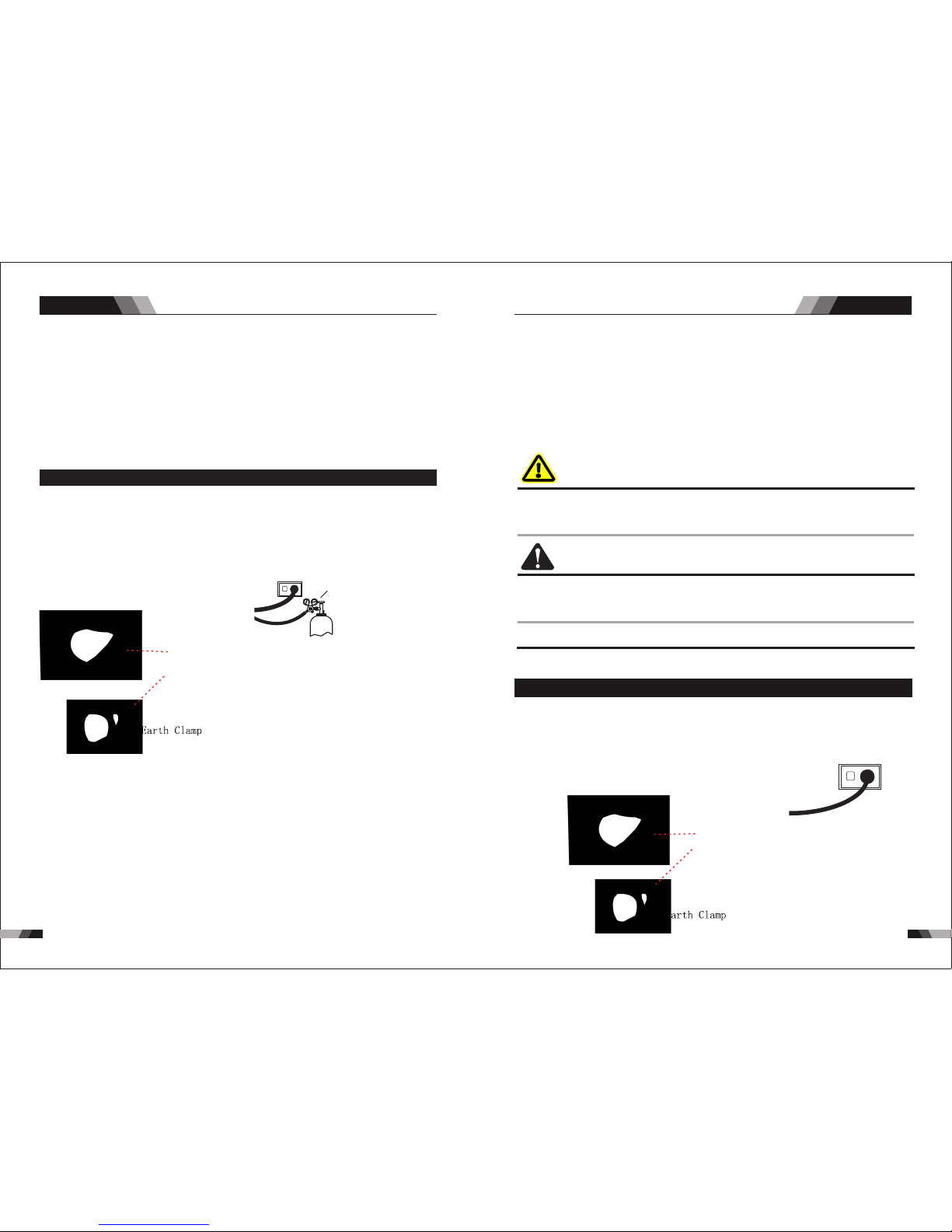
13 513 4
Ope ratio n Ope ratio n
Shu tdown
Clo se cylin der valve whene ver the re gulat or is not in use . To shut down for exte nded pe riods
(mo re than 3 0 minut es).
1. Cl ose cyl inder o r upstr eam val ve tigh tly.
2. Op en down strea m equip ment va lves to dra in th e lin es. B leed gas into a we ll ven tilated
are a and awa y from an y ignit ion sou rce.
3. Af ter ga s is d rai ned c omp let ely, di sen gag e ad jus tin g sc rew and cl ose do wn st ream
equ ipmen t valve s.
4. Be fore tr anspo rting c ylind ers tha t are not s ecure d on a cart des igned for su ch purp oses,
rem ove reg ulato rs.
2.11 Set-up MIG (GMAW) Welding With Gas Shielded MIG Wire
Whe n using a n on shie lded wi re, you n eed to ha ve an ext ernal g as source at tach ed to th e
uni t. For m ost N on Sh ield ed Wi re, c onn ect t he Wo rk Le ad t o the n egat ive - t ermi nal an d
con nect th e MIG G un po lar ity lea d to t he po sit ive + ter min al. I f in dou bt, consu lt the M IG
ele ctrod e wire ma nufac turer.
1. Tur n the Mai n ON/OF F switc h OFF (lo cat ed on th e rear p ane l).
2. Ch eck tha t the MIG w ire s ize, c onta ct tip, M IG Gu n line r and dr ive r oll gr oove a re all th e
sam e size be fore fi tting t he MI G wire i nto th e Pow er Sou rce.
3. Co nnect the MIG Gun Polar ity Lead to the po sitiv e weldin g termi nal (+). If i n doubt, consul t
the M IG elec tro de wir e manu factu rer. Wel ding c urren t flows f rom the P ower So urce vi a
hea vy duty ba yonet ty pe term inals . It is essen tial, ho wever, tha t the male p lug is i nserted
and t urned s ecure ly to ach ieve a so und ele ctric al conn ectio n.
4. Fi t the MIG w ire s pool a nd MIG G un to t he mac hine .
5. Co nnec t the w ork l ead t o th e neg ati ve w eld ing termi nal (- ). If in doub t, con sult the MI G
el ect rod e wir e man ufa ctu rer. W eld ing c urr ent f low s from th e Power S our ce via hea vy
dut y bayo net t ype t erm ina ls. It i s essenti al, ho wever, tha t the ma le plug is in sert ed and
tur ned sec urely t o achie ve a soun d elect rical c onnec tion.
Ens ure tha t the g as cyli nder is
secu red to a build ing pillar, wa ll
bra cket or oth erwi se sec urel y
fix ed in an up right p ositi on.
pow er supp ly
(Ar./ GAS(T IG/WI G))
MIG torc h
MIG SERIES EQUIPMENTMIG SERIES EQUIPMENT
6. Fi t the wel ding gr ade shi eldin g gas reg ulato r/ ow gaug e to the shieldin g gas cylin der then
con nec t th e sh iel di ng g as ho se f rom th e re ar o f ma chi ne to t he re gula tor/ ow gaug e
out let.
7. Tur n the Mai n ON/OF F switc h ON (l ocat ed on th e rear pa nel).
8. Se lect MI G mode wi th the pr oce ss sel ecti on cont rol.
9. Re move th e MIG Gun n ozzle a nd cont act tip .
10. D epress MIG Gun trigger to feed the MIG wi re out thr ough th e MIG Gun gas d iffu ser th en
fit t he co ntac t tip o n the MIG wir e and secu rely fa sten it to th e MIG G un th en fi t the
noz zle in pl ace.
11. Re fer to the Weld Guide located on the inside of th e wire fee d compa rtmen t door for fu rther
informa tion o n Voltage/ Wire speed set ting s.
Bef ore con necti ng the wor k clamp to the work make sure the m ains pow er supp ly is switched
OFF.
WAR NIN G
CA UTI ON
Loo se weld ing terminal conn ections can cause ov erheating and resul t in the male plug being
fused in the t ermi nal.
Depe nding on the type of wire you will be using the MIG Gu n polar ity may need to be switched.
Fol low the w ire man ufact urers r ecomm endat ion.
2.12 Set-up for MIG (FCAW) Welding with Gasless MIG Wire
When usi ng a gasle ss flux cored wire, you do not need to have an external gas source atta ched
to th e unit. F or most S elf S hiel ded Fl ux Core d Wire, c onnec t the Wor k Lead t o the pos itive
+ te rmi nal a nd co nne ct t he MI G Torc h pol arit y lea d to MIG to rch c onne ctor . If in do ubt,
con sult th e Flux Co red ele ctrod e wire ma nufac turer.
NO TE
pow er supp ly
MIG torc h
Sec ure the w eldin g grade s hield ing gas cyli nder i n an uprigh t posi tion by cha inin g it to a
sui table s tatio nary su pport t o preve nt fall ing or ti pping .
Rem ove an y pack agin g mate rial prior to u se. DO N OT bloc k the ai r vent s at the front or r ear
of th e Welding Pow er Sou rce.
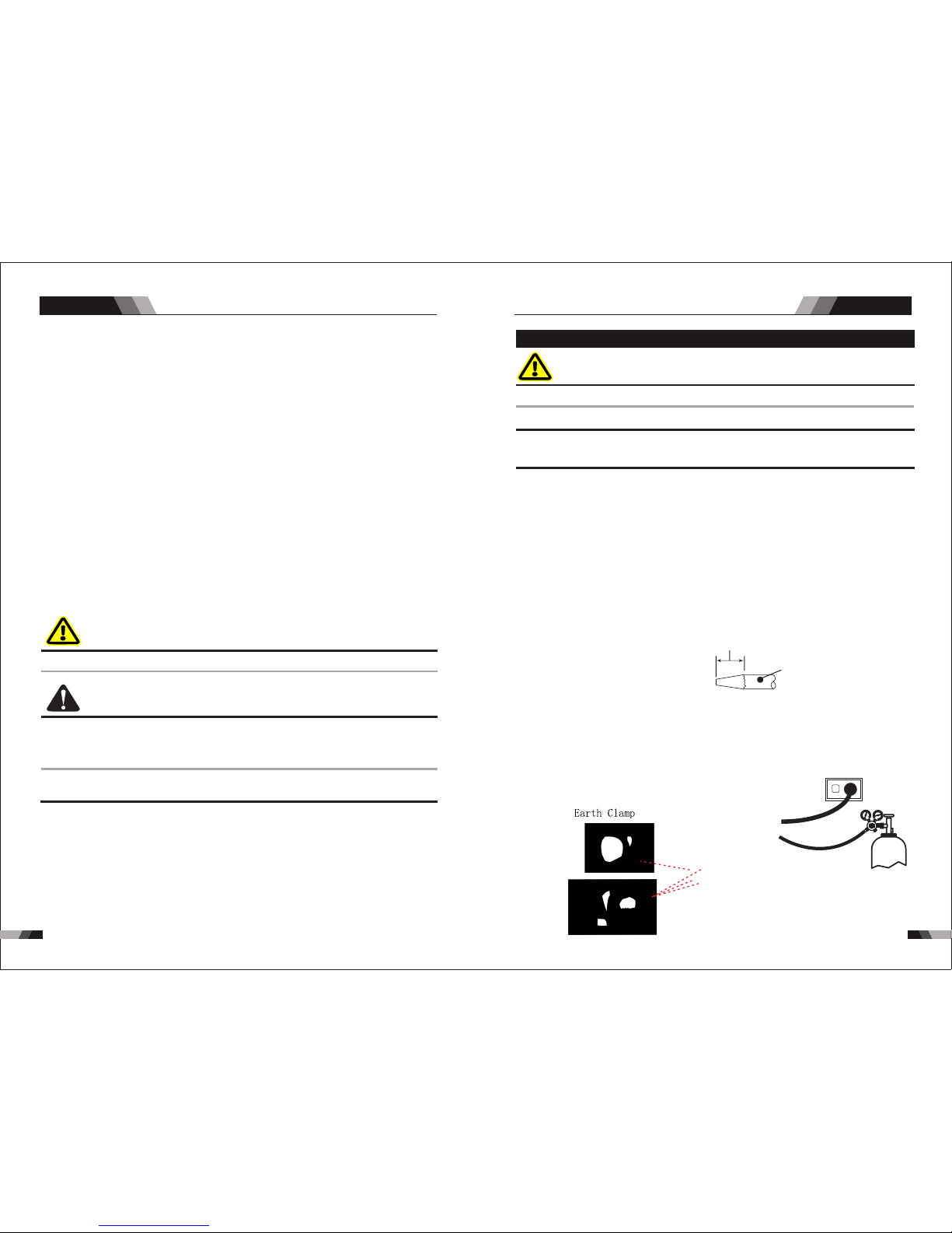
13 6 137
Ope ratio n
1. Tur n the Mai n ON/OF F switc h OFF ( loca ted on t he re ar pan el).
2. Ch eck tha t the MIG w ire s ize, c onta ct tip, M IG Gu n line r and dr ive r oll gr oove a re all th e
sam e size be fore tt ing t he MIG w ire in to the Po wer S ourc e.
3. Co nnect the MIG Gun Polar ity Lead to mig torch connec tor. If in doub t, consu lt the M IG
ele ctrod e wire ma nufac turer. Wel din g cu rre nt o ws f rom t he Po wer S our ce vi a heav y
dut y bayon et type t erm inal s. It is e ssent ial, however, th at the male plu g is inser ted an d
tur ned sec urely t o achie ve a soun d elect rical c onnec tion.
4. Fi t the MIG ( FCAW ) wire s poo l and MI G Gun to t he ma chin e.
5. Co nnec t the w ork l ead t o th e pos iti ve w eld ing t erm ina l (+) . If in doub t, con sult the MI G
ele ctrod e wire man u- factu rer. Weld ing curr ent ows fr om the Pow er Sourc e via he avy d uty
bay onet ty pe term ina ls. It i s esse nti al, ho weve r, that the male plug is insert ed and turned
sec urely t o achie ve a soun d elect rical c onnec tion.
6. If g asles s MIG (FC AW) wi re is fi tte d then s hiel din g gas is n ot req uir ed for w eldi ng.
Otherw ise fit the welding grade shield ing gas regul ator / ow gauge to the shielding gas
reg ulato r/ow ga uge out let.
7. Tur n the Mai n ON/OF F switc h ON (l ocat ed on th e rea r pane l).
8. Se lect MI G mode wi th the pr oce ss sel ecti on cont rol.
9. Re move th e MIG Gun n ozzle a nd cont act tip .
10. D epres s MIG Gun t rigge r to feed the M IG wire out t hroug h the MIG Gun gas diffuser then
fit t he co ntac t tip on th e MI G wir e and s ecu rel y fas ten it t o the MI G Gun t hen fi t the
noz zle in pl ace.
11. Re fer to th e Wel d Gui de lo cat ed on t he insi de of t he wi re fe ed co mpa rtm ent d oor f or
fur the r info rmat ion on Vol tage/ Wires peed se tting s.
WARN ING
Before connecting the work clamp to the work make sure the mains power supply isswitched OFF.
CAU TION
Loo se welding term inal connections can ca use ove rheat ing and re sult in the mal e plug bei ng
fus ed in the t ermin al.
Rem ove any pack agin g materia l prio r to use. DO NOT blo ck the air ve nts at the fr ont or rear
of th e Weld ing Power S ourc e.
Depe nding on the type of wire you will be using the MIG Gun polar ity may ne ed to be swit ched.
Fol low the w ire man ufact urers r ecomm endat ion.
NO TE
MIG SERIES EQUIPMENTMIG SERIES EQUIPMENT
2.13 Set-up For LIFT TIG (GTAW) Welding (only for R231)
WAR NING
Bef ore a ny wel ding is to b egin , be su re to w ear a ll app ropr iate an d reco mmend ed safe ty equi pment
The f ollow ing ste ps will a ssume t hat you h ave alr eady se t up the pr oper sh ieldi ng gas.
The fol lowin g set up is know n as Straigh t Polar ity or DC Elec trode Positi ve. This is commonly
use d for DC LI FT TIG we ldin g on mos t mater ials su ch as ste el and st ainle ss stee l.
7. In stal l the t ungs ten w ith a ppr oxi mate ly 1. 0mm t o 3. 2mm s tick ing ou t fro m the ga s cup,
ens uring y ou have c orrec t sized c ollet .
8. Tig hten th e back ca p.
9. Tur n the swi tch to th e “ON” po sitio n. The po wer L. E.D. li ght sho uld ill umina te.
10. S et the we lding p roces s to LIFT T IG.
11. Se t the We ld Cur rent Co ntrol K nob to th e desir ed ampe rage.
12. You are no w read y to begin LI FT TIG We lding.
NO TE
NO TE
power su pply
(Ar. /GAS( TIG/W IG)
TIG torc h
1.S witch t he ON/O FF Swit ch (l ocat ed on th e rea r pane l) to OF F.
2.C onnec t the wor k earth c lamp to t he po siti ve out put t ermi nal, a nd the LI FT TIG Torch
cab le to the n egati ve outp ut term ina l. Ref er to Fi gure 5- 02.
3.C onnec t the gas l ine/h ose to th e prope r shiel ding ga s sourc e. and co nnect t he avia tion
plu g for tri gger sw itch to 5 p in cont rol soc ket Ref er to F igur e 5-02 .
4.S lowly o pen the Ar gon Cyl inder Valve to t he full y open po sition.
5.C onnec t the wor k earth c lamp to y our wor k piece .
6.T he tun gste n must b e grou nd to a bl unt po int (similar to a pen cil) i n orde r to ach ieve
opt imum w eldi ng res ults . (Ref er to Fi gure : 5-01 ). It is critical to gr ind th e tung sten
ele ctro de in th e dire ctio n the gr indi ng whe el is tu rnin g. Grind at a 30 de gree a ngle a nd
nev er to a sh arp po int.
2 to 2- 1/2 Time s Elect rode Di amete r
Ele ctrod e
Ope ratio n
cyl inder t hen con nect th e shiel ding ga s hose fr om the re ar of t he mac hine t o the

13 91 38
Ope ratio n
2.14 Set- up For ST ICK Met al Ar c Welding (MMA)
WAR NING
Be for e any wel din g is t o beg in, be su re to wea r all appr opriate a nd rec omm ende d safe ty
equ ipmen t.
The f ollow ing set u p is know n as DC Ele ctrod e Posit ive or re verse p olari ty. Plea se con sult
wit h the STI CK elec trode m anufa cture r for spe cif ic pol arit y recom menda tions .
1. Sw itch th e ON/OF F Swi tch (l ocat ed on t he rea r pane l) to OFF.
2. Att ach the S TICK an d Work Le ads, conne ction a s pictu re.
3. Se t the wel ding pr ocess t o STICK .
4. Se t the Wel d Curr ent Con trol Kn ob to the d esire d amper age.
5. In stall a S TICK el ectro de in t he ele ctro de hold er.
6. You are now r eady t o begin STI CK Wel ding .
To weld , gentl y strike th e elect rode on th e work piec e to gener ate a we ldin g arc , and s lowl y
mov e along t he work p iece wh ile hol ding a consi sten t arc lengt h abov e base meta l.
NO TE
NO TE
power su pply
Ele ctrod e holdd er
MIG SERIES EQUIPMENTMIG SERIES EQUIPMENT
3.1 Troubleshoo ting
WAR NING
The re are ex treme ly dang erous v oltag e and pow er lev els p res ent i nsi de th is pr odu ct. Do
not att emp t to o pen o r re pai r unl ess you a re a q ual ifi ed el ectr ical tra des per son a nd you
hav e hard tr ainin g in powe r measu remen ts and tr ouble shooting t echn iques.
If ma jor complex suba ssemblies are faulty, then the Welding Power So urce mu st be returned
to an a ccred ited re selle r for rep air. The b asic l evel of trou bles hooting i s that w hich can be
pe rfo rme d wit hout spe cia l eq uip men t or kno wle dge .
Nr.
1
2
Troubles
Solution
Fan is broken
The power board is broken
There is something in the fan
The start capacitor of fan damaged
Tur n on the p ower
sou rce, po wer
ind icato r is lit, f an
is no t worki ng.
Tur n on the
pow er sour ce,
fan i s worki ng,
pow er indi cator
is no t lit
Reasons
Cha nge fan
Cle an it
Cha nge cap acito r
The p ower li ght dam aged or
con necti on is not g ood
Display panel is broken
Cha nge it
Cha nge it
Cha nge the p ower li ght
3
The power cable is broken
Tur n on the p ower
sou rce, fa n is not
wor king ,p ower
ind icato r is not li t
The p ower ca ble con necte d not
goo d
The light of the power indicator is
broken and the problems
mentioned in Nr. 2
Change the light of the power
indicator or refer to the solution
in Nr. 2
Cha nge it
Cha nge it
Rep air or ch ange it
Con nect co rrect ly
Pow er on swi tch is da maged
The p ower bo ard is br oken
4
6
Tur n on the p ower
sou rce, po wer
ind icato r is lit, f an
is wo rking , there
is no w eldin g
out put.
No no -load
vol tage ou tput
(MM A)
Con trol bo ard is br oken
st
1 in verte r circu it dama ged
If th e overh eat ind icato r is on
The m ain cir cuit is b roken
The m achin e is brok en
Cha nge it
Rep lace it
Wait a few minutes, the machine
can b e opera ted nor mal
Che ck and re pair
Con sult th e deale r or the
man ufact urer
Tro ubles hooti ng
5
The n umber o f the
dis play is n ot
int act
Dig ital tu be is bro ken
The d ispla y panel i s damag ed
Cha nge the d ispla y panel
Cha nge it

14 11 40
Tro ubles hooti ng
MIG SERIES EQUIPMENT
WELDING TECHNIQUE AND MAINTENANCE
Nr.
Troubles
Solution
Reasons
7
16
17
8
Tur n on the p ower
sou rce ,po wer
ind icato r is lit,
gas f lows, w ire
rol ler can not fee d
Tig electr ode melts
when wel ding (for
R231)
Arc flut ters during
Tig weldin g
Turn on the power
source ,power
indicator is lit ,gas
flows, wire feeding,
no arc igniting
The w ire rol ler is wr ong ins talle d
Che ck and ch ange it
Che ck and so rt it out
Che ck and co nnect c orrec tly
Che ck and in stall c orrec tly
Con sult th e deale r or the
man ufact urer
Cha nge to th e same si ze of
the n eeded p arts
The w ire rol ler is tw ined
Check th e welding circu it is correct
Contr ol board is broken
Check ing if the wire check ing
indic ator is on
Wire fee ding board(for R251 and
R311) is broke n or the cont rol board
( for R221 and R23 1) is broken
The min value displayed is n't
accor dant with the actu al value
The max value displayed is n't
accor dant with the actu al value
Con trol bo ard is br oken
Cor rect pr operl y
Che ck and co nnect c orrec tly
Con sult th e deale r or the
man ufact urer
The m ig torc h is not co rrect ly
fit ted to ma chine
The w ire is no t corre ctly th rough
the i nlet wi re guid e
Tun gste n elec trode i s too big f or
the w eldin g curre nt
Che ck the ea rth cla mp posi tion
on th e work pi ece
Tig t orch i s conn ected t o the
pos itive t ermin al
Con nect th e tig tor ch to
neg ative t ermin al
Sel ect the c orrec t size of
tun gsten e lectr ode
Adj ust the p ositi on of ear th
cla mp
The size of the groove ,wire and
torch tip are not from the same size
Pressure roll er arm is fitted firmly
10
11
13
14
Change it
Close the wire checking function
Consult the dealer or the
manufactu rer
Adjust potenti ometer Imin on
the control board
Adjust potenti ometer Imax on
the control board
Close it
Remove it
Gas a lways f lows
Wit hout tr igger ing
the m ig torc h but
the w ire rol ler
fee ding wi re
aut omati cally
The w eldin g
cur rent di splay ed
isn 't acco rdant
wit h the act ual
val ue
The p enetr ation
of mo lten po ol is
not e nough
Some thing is in the va lve
The arc is too long in the wel ding
proc ess
The wel ding curr ent is adjusted
too low
Incr ease the wel ding curre nt
Adju st the dista nce from torch
to work pi ece
Use the su itable le ngth from
manu facture r
The pow er cable or the we lding
cabl e is too long
Elec tromagn etic valv e is damaged
If the gas checking function is selected
Nr.
Troubles
Solution
Reasons
Tro ubles hooti ng
9
Gas cylinder is close or gas
pressure is low
Something is in the valve
Open or change the gas cylinder
Remove it
Change it
Change it
Pressure too high or air regulator is
broken
Check gas
No ga s flow (T IG)
Elec tromagn etic valv e is damaged
Air tub e is brocken
12
Checking if the electorde stick to
the work piece that the anti-stick
function is on
Repair or change it
The w eldin g
cur rent ca nnot
be ad juste d
Cont rol board is br oken
Shut off the power when changing the tor ch
Sep arate t he elec trode a nd
wor k piece
15
Over-heat prot ection ,too much
welding curren t
Reduce the welding current
Reduce the welding time
Over-heat prot ection ,working too
much time
Over-curr ent protection, current in
the main circuit is out of control
Check and repair main circuit
and drive board
Thermal overload
indicator light is on
Check the power supply
Change the fan
Inpu t voltage is to o low
Fan is bro ken

14 31 42
WELDING TECHNIQUE AND MAINTENANCE
TIG Welding App lica tio n Shot
1.1 TIG Basic We lding Tec hniqu e
Gas Tu ngste n Arc Weldi ng (GTAW ) or TIG ( Tung sten I nert Gas) a s it is co mmon ly refe rred
to , is a welding p roc ess i n whi ch fu sio n is pr odu ced b y an el ect ric a rc th at is e sta bli she d
be twe en a si ngl e tun gst en (n on- c ons uma ble ) ele ctrode a nd th e wor k pie ce. S hie ldi ng is
obt ained f rom a wel ding gr ade shi elding gas o r weld ing grade s hiel ding gas mi xtur e which
is ge neral ly Argo n based . A fill er meta l may als o be added manu ally in s ome circums tanc es
dep endin g on the we lding appl icat ion.
Gas C up
Eit her Cer amic,
Hig h-lmp act or
Wat er Coo led
Met al
Wor k Piec e
can B e Any C omme rcia l
Met al
Wel ds Mad e With o r
Wit hout Add ition
of Fi ller Me tal
Ine rt Gas
Shi elds El ectro de
and W eld Pu ddle
Tun gste n Elec trod e
Non -Cons umabl e
1.3 The explanat ion of we lding quality
The rela tio n of we lding are a col or & pr otect eff ect o f sta inless st eel
Pro tect ef fect
bes t bet ter
goo d
bad
wor st
Wel ding a rea col or arg ent ,gol den
blu e
red -grey
gre y
bla ck
a butt jo int b lap joi nt c coner j oint d T joint
1.2 Joint froms in T IG
TIG W eldin g
WELDING TECHNIQUE AND MAINTENANCE
WELDING TECHNIQUE AND MAINTENANCE
CHAPTER 7
Bas ic know ledge

14 514 4
WELDING TECHNIQUE AND MAINTENANCE
TIG W eldin g
TIG W eldin g
WELDING TECHNIQUE AND MAINTENANCE
Parame ter s of pi ping back s eal ing w elding fo r mil d steel(DCEP )
Piping
diameter
Φ/mm
Tungsten
electrode
diameter/mm
Gas nozzle
diameter/mm
Welding
wire diameter/mm
Welding current/A
Welding
current/A
Arc
voltage/V
Argon flow
1
rate/L•min-
Welding
1
rate/cm•min-
38
42
60
76
108
133
159
219
273
325
2.0
2.0
2.0
2.5
2.5
2.5
2.5
2.5
2.5
2.5
8
8
8
8~10
8~10
8~10
8~10
8~10
8~10
8~10
2
2
2
2.5
2.5
2.5
2.5.
2.5
2.5
2.5
75~90
75~95
75~100
80~105
90~110
90~115
95~120
100~ 120
110~ 125
120~ 140
11~13
11~13
11~13
14~16
14~16
14~16
14~16
14~16
14~16
14~16
6~8
6~8
7~9
8~10
9~11
10~12
11~13
12~14
12~14
12~14
4~5
4~5
4~5
4~5
5~6
5~6
5~6
5~6
5~6
5~6
Not ice: th e above p arame ters or igina te from < <Weld ing Di ction ary>> P 167,
Volu me 1 of E diti on 2.
TIG of sta inl ess s teel(si ngl e run w elding)
Workpiece
thickness
/mm
Joint form
tungsten
electrode
diameter
/mm
welding
wire
diameter
/mm
Argon gas
flow rate/
1
L•min-
welding
current
(DCEP)
Weld ing
spee d/
cm•m in-1
0.8
1.0
1.5
1.5
2.4
2.4
3.2
3.2
4.8
4.8
6.0
Butt joint
Butt joint
Butt joint
Corner joint
Butt joint
Corner joint
Butt joint
Corner joint
Butt joint
Corner joint
Butt joint
1.0
1.6
1.6
1.6
1.6
1.6
1.6
1.6
2.4
3.2
4.0
1.6
1.6
1.6
1.6
2.4
2.4
2.4
2.4
3.2
3.2
4.0
5
5
7
7
7
7
7
7
8
9
10-12
20~50
50~80
65~105
75~125
85~125
95~135
100~135
115~145
150~225
175~250
220~300
66
56
30
25
30
25
30
25
25
20
25
Not ice: th e above p arame ters or igina te from < <Weld ing Di ction ary>> P 150,Vo lume 1 of E ditio n 2.
1.4 TIG Paramete rs Matc hing
The corr esp ond ing relat ion shi p between g as no zzle
diamet er an d ele ctrode di ame ter
Gas n ozzle d iamet er/mm
6.4
8
9.5
11.1
Ele ctrod e diame ter/m m
0.5
1.0
1.6 o r 2.4
3.2
Not ice: th e above p arame ters or igina te from < <Weld ing Di ctio nary> > P142, Volume 1 o f Editi on 2.
04
Gas nozz le an d the s hield gas f low r ate
Welding
current range/A
DC positive connection
AC
Gas nozzle
diameter/mm
Gas flow
1
rate/L•min-
Gas nozzle
diameter/mm
Gas flow
1
rate/L•min-
10~100
101~150
151~200
201~300
4~9.5
4~9.5
6~13
8~13
4~5
4~7
6~8
8~9
8~9.5
9.5~11
11~13
13~16
6~8
7~10
7~10
8~15
Not ice: th e above p arame ters or igina te from < <Weld ing Di ction ary>> P 149,Vo lume 1 of E ditio n 2.
Pro tect ef fect
bes t bett er
goo d
bad
wor st
Wel ding a rea col or br ight a rge nt ora nge- yellow
blu e-pur ple
cae sious
whi te powd er
of ti taniu m oxid
The rela tio n of we lding are a col or & pr otect eff ect o f Ti-a llo y
Tungsten
Electrode
Diameter/mm
Sharpened of
the Electrode
Diameter/mm
Angle of Cone(º)
Background
Current/a
1.0
1.0
1.6
1.6
2.4
2.4
3.2
4.0
0.125
0.25
0.5
0.8
0.8
1.1
1.1
1.5
12
20
25
30
35
45
60
90
2~15
5~30
8~50
10~70
12~90
15~150
20~200
20~300
Tung ste n Ele ctrode

14 714 6
WELDING TECHNIQUE AND MAINTENANCE
WELDING TECHNIQUE AND MAINTENANCE
Tungsten Electrode Types
TIG Welding Filler Rods
TIG W eldi ng is gen erall y regar ded as a sp ecial ized pr ocess t hat req uires o perat or
com peten cy. Whil e many o f the pri ncipl es outl ined in t he prev ious Arc W elding se ctio n are
app licab le a comp rehen sive outli ne of th e TIG We ldin g process i s outs ide the sco pe of th is
Ope ratin g Manua l.
Not ice: th e above p arame ters or igina te from《W eldi ng Dict ionary》P53 8,
Volu me 2 of E diti on 2.
Parame ter s of AC TI G(M MA) for Aluinum and it s all oy
Steet
thickness
/mm
Welding
wire
diameter
/mm
Tungsten
eletrode
diameter
/mm
Pre-heat
Temper
-ature/ºC
Welding
current/A
Argon flow
1
rate/L•min-
Gas nozzle
diameter
/mm
Remark
1.6
1.6~2.0
2~2.5
2~3
3
3~4
4
4~5
4~5
2
2
2~3
3
4
4
5
5
5
100
100~150
45~60
50~80
90~120
150~180
180~200
180~240
240~280
260~320
280~340
1
1.5
2
3
4
5
6
8
10
7~9
7~9
8~12
8~12
10~15
10~15
16~20
16~20
16~20
8
8
8~12
8~12
8~12
10~12
14~16
14~16
14~16
Flange welding
Flange or butt
welding by
one side
Butt welding
V-groove
butt welding
12
14
16
18
20
16~20
22~25
4~5
5~6
5~6
5~6
5~6
5~6
5~6
5~6
5~6
6
6
6
6
6~7
150~200
180~200
200~220
200~240
200~260
200~260
200~260
300~360
340~380
340~380
360~400
360~400
300~380
360~400
18~22
20~24
20~24
25~30
25~30
25~30
30~35
16~20
16~20
16~20
16~20
20~22
16~20
20~22
X-groove
butt welding
1.5 E-Ser ies Equ ipmen t TIG Parameters Matchi ng
Tung sten E lectr ode Cur ren t Rang es
Gui de for Se lec ting F ille r Wir e Diam eter
TIG W eldin g
TIG W eldin g

14 914 8
MMA W eldin g
WELDING TECHNIQUE AND MAINTENANCE
The Welder
Pl ace y oursel f in a c omf ort abl e po sit ion b efo re be gin nin g to w eld . Get a sea t of s uit abl e
he igh t an d do as muc h wor k as po ssi ble sit tin g dow n. Do n't h old y our b ody t ens e. A tau t
at tit ude o f mi nd an d a ten sed bod y wi ll so on ma ke you fe el t ire d. R ela x an d you w ill f ind
th at t he j ob be com es m uch e asi er. Yo u can add muc h to y our pea ce of m ind b y wea ring
a leat her a pro n an d ga un tle ts. Yo u wo n' t be w or ryi ng th en abou t bei ng bu rnt or spar ks
set ting al ight to y our clo thes.
Pl ace th e wor k so th at th e dire cti on of w eldi ng is ac ros s, rat her th an to o r from y our bo dy.
Th e el ect rode ho lder le ad sh oul d be cl ear o f an y obs tru cti on so t hat y ou c an mo ve yo ur
a rm f re ely al ong as t he e lec tro de b urn s do wn . If t he l ead is s lu ng o ve r yo ur s hou lde r,
it allow s gre ater f ree dom of m ove ment a nd ta kes a lo t of we ight o ff your h and. B e sure t he
in sul ati on o n you r cab le a nd el ect rod e hol der is no t fau lty, oth erw ise y ou ar e ris kin g an
ele ctric s hock.
WELDING TECHNIQUE AND MAINTENANCE
2.1 MMA Basic Weldin g Technique
Arc Welding Practice
Th e tec hn iqu es us ed fo r arc wel di ng ar e alm ost i den ti cal reg ar dle ss of w hat t ype s of
me tal s are b eing joi ned . Nat ura lly e noug h, differ ent types of el ect rod es wo uld b e use d
for d iffer ent me tals as d escri bed in th e prece ding se ction .
Welding Position
Th e el ec trode s de al t wi th i n th is p ub li ca tio n ca n be used i n mo st p osi tions , i. e. t hey
ar e su ita ble for w eld ing in fl at, h ori zon tal , ver tic al an d ov erh ead pos ition s. Nume rou s
ap plica tio ns ca ll f or weld s to b e ma de in pos ition s in ter media te b etw een the se. S ome
of th e commo n types o f welds a re show n
Fla t Posit ion,
Dow n Hand Bu tt Weld
Fla t Posit ion,
Gra vity Fi llet We ld
Hor izont al Posi tion,
But t Weld
Hor izont al-Ver tical
(HV ) Posit ion
Vert ical Po sitio n,
But t Weld
Vert ical Po sitio n,
Fil let Wel d
Vert ical Po sitio n,
Fil let Wel d
Ove rhead P ositi on,
Fil let Wel d
Joint Prep ara tio ns
In m any c ases, it w ill b e pos sib le to w eld s tee l sec tio ns witho ut an y spe cial pre par ati on.
For h eavier sect ions and for re pair wo rk on ca sting s, etc ., it wil l be necessar y to cut or g rind
an a ngl e bet wee n the p iec es be ing jo ined t o ensu re pro per pe netr ati on of t he wel d meta l
and t o produ ce soun d joint s.
In ge neral , surfa ces bei ng weld ed shou ld be cle an and fr ee of rus t, scal e, dirt , greas e, etc.
Sla g shoul d be remo ved fro m oxy-c ut surf aces.
Arc Welding Techn iqu e - A Word to Beginners
For those who h ave not yet done an y weldi ng, the s imple st way to co mmenc e is to run be ads
on a pi ece of sc rap pla te. Use m ild ste el plat e about 6 .4mm (1 /4") th ick and a 3 .2mm (1 /8")
el ectr ode . Cle an any p aint , loose sca le or g rea se off t he pl ate and set i t fir mly o n the work
ben ch so th at wel ding can be car ried o ut in th e down hand positi on. Ma ke sur e that t he work
cl amp i s mak ing g ood electrical c ont act w ith t he wo rk, e ithe r dire ctly or th rou gh th e wor k
ta ble . For l ight gau ge ma ter ial , alway s cla mp th e wor k lea d dir ect ly to the j ob, o the rwi se
a poo r circu it will p robab ly resu lt.
MMA W eldin g
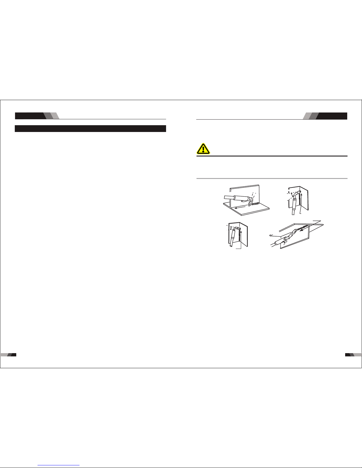
15 11 50
MIG W eldin g
WELDING TECHNIQUE AND MAINTENANCE
MIG W eldin g
WELDING TECHNIQUE AND MAINTENANCE
Th e MIG Gun s hou ld be hel d at an a ng le t o th e we ld j oin t. (S ee S eco nda ry A dju stm ent
Vari able s below )
Hol d the MIG G un so tha t the wel ding se am is vie wed at a ll tim es. Alwa ys wear t he welding
hel met wit h prope r filte r lense s and use t he prop er safe ty equi pment .
WAR NIN G
Do NO T pull the M IG Gun b ack when th e arc is e stablis hed. T his wi ll creat e exce ssiv e wir e
ex- t ensio n (stic k-out ) and mak e a very po or weld .
The e lectr ode wir e is not en ergiz ed until t he MIG Gun tr igger sw itch i s depr esse d. The w ire
may t heref ore be pl aced on t he seam o r joint p rior to l oweri ng the he lmet.
Dis tance f rom the M IG Gun No zzl e to the W ork Pi ece
The el ectrode wir e stick out from the MIG Gun nozzle should be between 10 - 20 mm (3/8" - 3/4").
Thi s dista nce may v ary dep endin g on the ty pe of joi nt that i s being w elded .
Trav el Spee d
The s peed at wh ich the mo lten po ol trave ls influence s the wid th of th e wel d and pe netr ati on
of th e weldi ng run.
Est ablis hing th e Arc an d Maki ng Wel d Bea ds
Bef ore att empti ng to weld on a fi nishe d piece of wo rk, it is rec ommen ded that pra ctic e welds
be ma de on a sam ple met al of the s ame mat erial a s that of t he fini shed pi ece.
The e asies t weldi ng proc edure f or the be ginne r to expe rimen t with MI G weldi ng is the f lat
pos ition . The equi pmen t is capabl e of fla t, vertic al and o verhead p osit ions.
For p racti cing MI G weldi ng, sec ure som e piece s of 1.6 mm o r 5.0 mm (1 /16 " or 3/1 6") mi ld
ste el plate 15 0 mm x 150 mm (6" x 6"). U se 0.9 m m (.035 ") flux co red gas less wi re or a sol id
wir e with sh ieldi ng gas.
Dis tance f rom the M IG Gun No zzl e to the W ork Pi ece
The e lectrod e wire stick out from the MIG Gun noz zle should be between 10 - 20 mm (3/8" - 3/4").
Thi s dista nce may v ary dep endin g on the ty pe of joi nt that i s being w elded .
Trav el Spee d
The s peed at w hich th e molten p ool trav els influenc es the w idth o f the we ld an d pene trat ion
of th e weldi ng run.
3.1 MIG (GMAW /FC AW) Ba sic Welding Technique
Two di ffere nt wel ding proce sses a re covere d in thi s sec- tion (GMAW and FCAW), wi th the
int entio n of pro vidi ng th e ver y bas ic co nce pts i n usi ng th e MIG mo de of weldin g, whe re a
MIG G un is ha nd held , and t he el ect rod e (we ldin g wire ) is fed in to a we ld pu ddle , and th e
arc is s hield ed by an iner t welding grade sh ieldi ng gas o r ine rt w eld ing g rade s hiel din g gas
mix ture.
GAS METAL ARC WELDING (GMAW ): This pro cess, also known as MIG weld ing, Co wel ding,
2
Mic ro Wire Wel ding, sh ort arc we lding , dip tran sfer welding , wire w eldi ng et c., is a n elec tri c
arc w elding proce ss which fus es toge ther the par ts to be wel ded by heat ing them with an ar c
bet ween a so lid con tinuo us, con sumab le electro de and t he work.
Sh iel din g is o bta ine d fro m an ex ter nal ly s upp lie d wel ding g rad e shie ldin g gas o r weld ing
gra de shie lding g as mix- t ure. Th e proc ess is no rmall y applied semi aut omatica lly; howe ver
the p roces s may be op erate d autom atica lly and c an be machin e oper ated. The pro cess ca n
be us ed to wel d thin an d fairl y thick s teels , and som e non-f errou s metal s in all po sitio ns.
FLU X CORED AR C WELDI NG (FCA W): Th is is an el ectric arc weldi ng process w hich f uses
tog ether the parts to be welded by hea ting th em with an ar c betwee n a contin u- ous flux filled
ele ctrode wi re and the w ork. S hiel ding is obtai ned th rough deco mposi tion of t he flux wit hin
the tubu lar wire. Additio nal shieldi ng may or may not be ob- t ained fr om an externa lly supplied
gas or gas mixtu re. The proc ess is nor mally a pplie d semi automati cally ; however the process
ma y be appl ied a uto mat ica lly o r by mach ine . It is com mon ly used to w eld l arge d iame ter
ele ctrod es in the fla t and horizonta l positi on and s mall e lec trod e diam ete rs in al l posi tions .
The p roces s is used t o a lesse r degre e for wel ding st ainle ss stee l and for o verla y work.
Pos ition o f MIG Gun
The a ngle of M IG Gun to t he we ld has a n effe ct on th e width o f the wel d.

15 2
◆War ning :For s afety w hil e main tain ing t he mac hine ,pl ease s hut of f the
sup ply pow er an d wait f or 5mi nut es,u ntil c apa city v olta ge al read y drop
to sa fe volt age 3 6V!
O bs erv e th at w he the r pa nel kn ob a nd s wi tch in t he f ro nt a nd a t th e
ba ck of ar c we lding mac hin e ar e fl exi ble ane pu t co rrect ly in pl ace .If
th e knob h as not b een p ut co rrec tly i n pla ce, p leas e cor rec t, If you can ’t
cor rect or f ix the kn ob, ple ase rep lace im media tely
If t he sw itc h is no t fle xib le or i t can’t b e put c orre ctly in pl ace , ple ase
re pla ce i mme dia tel y; P lea se g et i n to uc h wi th m ain ten anc e se rvi ce
dep artme nt if the re are no a ccess ories
Af ter tu rn -o n po we r, wa tc h/ li st en t o th at w het he r th e ar c we ldi ng
ma ch ine h as sh aki ng, whi stl e calli ng o r pe cul iar s mell. I f the re is o ne
of th e abo ve p robl em s, f in d ou t th e re as on to g et r id o f, i f yo u ca n’ t
fi nd o ut th e rea son , Pl eas e co nta ct l oca l this ar ea a gen t or t he bran ch
com pany
Ob ser ve t hat w het her the d isp lay v alu e of L ED i s int act . If t he
di spl ay nu mber is no t int act, ple ase r epl ace t he da mag ed LE D. If it st ill
doe sn’t wo rk, ple ase mai ntain o r repla ce the di splay P CB
Ob serv e tha t whet her t he mi n/ma x val ue on LE D acco rds wi th th e set
va lue .If t here is a ny di ffer enc e and it ha s aff ect ed th e no rma l we ldi ng
cra ft, ple ase adj ust it
Chec k up that Whe ther fa n is damage d and is nor mal to rotate or cont rol
. If the fan i s dam age d,p lea se c han ge i mme dia tel y.If t he fa n doe s not
rot ate af ter the a rc wel ding ma chin e is overheat ed, ob serv e that wh ethe r
th ere is some thin g blo cke d in th e blad e,if i t is bl ock ed, plea se get r id of ;
If th e fan doe s not rot ate aft er ge ttin g rid of t he ab ove pr oble ms, you c an
pok e the bla de by the r otati on dire ction o f fan.I f the fan r ota tes no rmal ly,
the s tart ca pacit y shoul d be repl aced; I f not, ch ang e the fa n
Ob ser ve t hat whe the r th e fas t con nec tor is l oos e or o ver hea ted . If
th e arc w eld ing m ach ine h as the a bove p robl ems, it sh oul d be fa sten ed
or ch anged
Obs erv e that W heth er th e curr ent ou tpu t cabl e is dam age d. If it i s
dam aged, i t shoul d be wrap ped up, i nsula ted or ch anged
Usi ng the dr y compr esse d air to cl ear the i nside of arc wel ding m achin e.
Es peci all y for clea ring u p the d usts on rad iat or, ma in vo ltag e tra nsf orme r,
ind uctan ce, IGB T mod ule, th e fast re cover d iode an d PCB, et c
C hec k up the bo lt in a rc we ldi ng ma chi ne, if it is lo ose ,pl eas e scr ew
do wn it .If it is skid, pl ease r epl ace .If i t is ru sty,p lea se er ase r ust o n bol t
to en sure it w orks we ll
Wh ethe r the a ctu al cu rrent acc ords w ith t he di spl ayi ng value. If the y
does not a cco rd, th ey sho uld be r egul ated .Th e actu al cur rent v alue c an
be me asure d by the ad juste d plier -type a mpere m eter
Me asu re the insulat ing i mpe dan ce am ong t he ma in circui t,PC B and
ca se, if it bel ow 1MΩ, ins ula tio n is t hou ght to be dam age d and n eed t o
cha nge, an d need to c hange o r stren gthen i nsula tion
Date
Dai ly
exa minat ion
Mon thly
exa minat ion
Qua rter-
yea rly
exa minat ion
Year ly
exa minat ion
Mainte nan ce it em
4.1 Maintenanc e
In or der to g uara ntee t hat ar c welding machi ne wor ks hig h-efficientl y and in s afet y,it mus t
be ma inta ined r egul arly. Let cu stom ers un ders tand the maintenance me thod s and me ans
of arc wel din g ma chi ne m ore , en abl e cu sto mer s to c arry o n si mpl e ex ami nat ion and
sa feg uard ing by o nese lf, try o ne’s best to re duce the f ault rate and r epai r time s of ar c
wel ding ma chine , so as to le ngthe n servi ce life o f arc wel ding ma chine .Main tenan ce
ite ms in det ail are i n the fol lowin g table .
WELDING TECHNIQUE AND MAINTENANCE
Est ablis hing th e Arc an d Maki ng Wel d Bea ds
Bef ore attempti ng to weld on a fin ished pie ce of work , it is recom mende d that pra ctice we lds
be ma de on a sam ple met al of the s ame mat erial a s that of t he fini shed pi ece.
The e asies t weldi ng proc edure f or the be ginne r to expe rimen t with MI G weldi ng is the f lat
pos ition . The equi pmen t is capabl e of fla t, vertic al and o verhead p osit ions.
For p racti cing MI G weldi ng, sec ure som e piece s of 1.6 mm o r 5.0 mm (1 /16 " or 3/1 6") mi ld
ste el plat e 150 mm x 150 mm (6" x 6") . Use 0.9 mm (. 035") fl ux cor ed gas les s wire o r a soli d
wir e with sh ieldi ng gas.
Set ting of t he Po wer So urce
Powe r sour ce and Wir efeed er setti ng requ ires som e pract ice by the op erato r, as the w eldi ng
pla nt has tw o contr ol setti ngs that hav e to bal anc e. The se are t he Wir esp eed co ntro l (re fer
to se ction 3 .06.4 ) and the w eldin g Voltag e Cont rol ( ref er to sec tio n 3.06 .10). The weldi ng
cu rre nt is det erm ine d by t he Wi res pee d con trol, the cur ren t wil l inc rea se with inc reas ed
Wir espee d, resu lting i n a short er arc. L ess wir e speed w ill redu ce the cur rent and l ength en
the a rc. Incr easing the weld ing vol tage har dly alt ers the cur rent le vel, but l ength ens the arc.
By de creas ing the v oltag e, a shor ter arc i s obtai ned wit h a littl e chang e in curr ent lev el.
Whe n changi ng to a diffe rent ele ctrode wire dia meter, di ffere nt control sett ings are r equir ed.
A thin ner ele ctrod e wire ne eds mor e Wires peed to a chiev e the sam e curre nt leve l.
A satis factory weld ca nnot be ob taine d if the Wirespeed and Voltage sett ings are not adjust ed
to su it the el ectro de
wir e diame ter and t he dime nsion s of the wo rk piec e.
If th e Wire spee d is to o high fo r the wel din g vol tage , “stu bbin g” wi ll occ ur as th e wir e dips
int o the m olt en po ol an d doe s not m elt . Wel ding in th ese con dit ion s norm all y prod uces a
poo r weld du e to lack o f fusio n. If, ho wever, t he weldi ng volta ge is to o high , large dro ps will
for m on the en d of the wi re, cau sing sp atter. T he cor- rect sett ing of vo ltag e and Wi respe ed
can b e seen in the shape of the w eld depo sit and he ard by a smoo th regula r arc sou nd. Refer
to the Weld Guide located on the insid e of the wirefe ed compartm ent door for setup information.
Ele ctrod e Wire Si ze Se lect ion
The c hoice o f Elect rode wi re size a nd shie lding g as used d epends on th e foll owing:
Thi cknes s of the me tal to be w elded
Type o f joint
Cap acity o f the wir e feed un it and Po wer Sou rce
The a mount o f penet ratio n requi red
The d eposi tion ra te requ ired
The b ead pro file de sired
The p ositi on of wel ding
Cos t of the wi re
WELDING TECHNIQUE AND MAINTENANCE
Mai ntena nceMIG We lding
15 3
 Loading...