

Vector Welding V1841, V241, V341, C71, C101 Operating Instructions Manual
...
Register now
and benefit!
Jetzt Registrieren
und Profitieren!
www.vector-wel ding.com
VECTOR WELDING TECHNOLOGY
GmbH
3
Year s5Year s
transformer
and rectifier
OPERATING INSTRUCTIONS
Welding Machine

VEC TOR DIG ITAL – We op timiz e the qua lit y and pr ices
Loo king to th e future , susta inability, envi ronme nt friendly and h igh on the cu stome r-ori ented
com peten ce - the ke y words t o which w e are res ponsi ble.
For t his rea son, we d evelo p our own p owerf ul bran d VECTO R .
In VE CTO R we ld ing eq ui pm ent co mb ine s ad va nc ed i nv er te r te ch no logy, the hi gh est
qua lity st andar ds of a pre mium br and and l ow pric es to a uni que val ue for mo ney. Inv erte r
te chn olo gy is an e sse nti al c ompon en t of p roces s im pr ove men t an d mi nim ize s en ergy
co nsu mpt ion . In a ll ou r equ ipm ent, we th ere for e tr ust o n th e MOS FET t ech nol ogy f rom
Tos hib a and Inf ine on I GB T techn ol ogy fro m SIE MEN S. T hei r inn ova tive so lut ion s ar e
set ting ne w stand ards in w eldin g techn ology.
VE CTOR w eldi ng eq uip men t can b e use d on ne arl y all w eld a ble m etal s. It is p arti cul arl y
su ita ble w hen qua lit y wel ds a re ex tre mel y im por tan t. Pr iva te ga rdeni ng - m oto rcycl es,
ca rs, truck s, cl ass ic cars, mo del ma kin g, stair an d balc ony r ailings o r in the p rof ess iona l
an d in dus tri al se cto rs such a s Oil p ipe lin e, ch emi cal , autom oti ve, s hipbu ild ing , boile r,
el ect ric p owe r con str uct ion , nuc lea r pow er, ae ros pac e, mi lit ary, i ndu str ial ins tal lat ion ,
br id ge c on st ru ct io n an d ot he r in dus tr ie s, t he h ig he st q uali ty r equ ir em en ts a re m et
suc cessf ully wi th VECT OR wel ding eq uipme nt.
V EC TO R is on e o f t he l ea di ng s up pl ie rs o f we ld in g eq ui pm en t - d is co ve r ou r
po ssi bi lit ies - pro fit f rom our v isi on to off er mo der n, hi gh- pe rfo rma nc e we ldi ng
equ ipmen t at unbe ata ble pr ices .
On the bas is of 4 s tra tegic obj ect ive s, our comp any w ork d ay by
day to opt imi ze th is vision :
◆Number 1 i n Tech nology
◆Number 1 i n the p ric es
◆Number 1 i n Ser vic e
◆Number 1 i n the e nvi ronment al co mpa tibilit y
Mo re th an 30,000 e nthu sia sti c cus tome rs tru st ou r equ ipm ent i n the w elding an d plas ma
te chnol ogy. The y co nfi rm th e suc cess of the se t ren dse tti ng st ra teg y. In a ddi tio n to th e
st ring ent qu ali ty te st and the te st in th e pro duc tion, we subje ct th e equ ipm ent a t horo ugh
ins pection befor e delive ry. We guara ntee delivery of spare pa rts and re pair of al l equip ment.
The c ustom er is ser ved dur ing and a fter th e warra nty per iod fro m us. In ca se of p robl ems,
call us , we are alwa ys availa ble. You are also welc ome to visit us . Highly qua lified employees
are d edic ated t o carr ying o ut the ir various ta sks wi th exp erti se and p assi on. Ou r moti vate d
tea m will al ways fi nd a posi tive so luti on for yo u. Ever yone is w elco me to tes t our equ ipmen t
in de tail un der the g uidan ce of our e xpert s.
Pri vate g arde ning , indu stry o r prof essi onal, in eve ry are a you wi n if you r ely on t echn olog y
of we lding e quipm ent fro m VECTO R.
For q uesti ons or su gge stio ns, pl eas e cont act us .ww w.vec tor -wel ding .co m
WARNINGS
Read and u nde rst and this en tir e Man ual and you r emp loy er’ s safety
practi ces b efo re instal lin g, op erating , or se rvi cing the eq uip men t.
While Th e ope rating in str uctions prov ide a n introducti on to t he safe
use of the p rod uct s.
• Read the o per ati ng instru cti ons f or all syst em co mpo nents!
• Observ e acc ide nt preven tio n reg ulation s!
• Observ e all l oca l regulat ion s!
• Confir m wit h a sig nature wh ere a ppr opriate .
Record the f oll owi ng in for mat ion f or Warranty purpose s:
Whe re Purc hased :
Pur chase D ate:
Ser ial NO. :
Publis hed b y:
VECTOR W ELD ING TE CHN OLOGY GMB H
Hanses tra sse 1 01.
5114 9, Ko ln, G ermany
www.vec tor -we lding.c om

Safety instruction
1. 1 Arc w eldi ng dem age ---- ---- ---- --- ---- --- ---- --- ---- --- ---- ---- ---- --- ---- --- ---- --- 01-0 4
1. 2 Effe cts of low fr equ ency e lec tric a nd mag neti c fie lds---- --- ---- --- ---- --- ---- 0 4-04
1. 3 Symb ol cha rt -- ---- ---- ------- --- ---- ---- ------- --- ------- --- ------- --- ------- --- ---- 0 5-05
V-Ser ie s- --- ------- ---- --- --- ---- ---- --- --- ---- ---- --- --- ---- ---- --- --- ---- ---- --- -- 06 -06
C- Se ries--- ---- ---- ------- --- --- ---- ---- --- ---- --- --- ---- ---- --- ---- --- --- ---- ---- - 50- 50
E- Se ries - --- ---- ---- --- --- ---- ---- --- ------- ---- --- ------- --- --- --- ---- ---- --- --- -- 33-33
1. 1 Brief int rodu cti on-- --- --- ---- ---- --- ---- --- --- ---- ---- --- ---- ---- ------- --- --- ---- -- 07- 08
1. 1 Bri ef in tro duc tio n--- ---- --- --- --- --- --- --- ---- ------ --- --- --- --- ---- ---- ------ --- - 51- 51
1. 1 Bri ef in tro duc tio n-- --- ------- ---- --- --- --- --- --- --- --- --- --- ------- ---- --- --- --- --- 3 4-3 4
1. 2 Spe cif ica tio ns C4 1-- --- ------- ---- --- --- --- --- --- --- ------- ---- --- --- --- --- --- --- - 51- 52
1.2 Work ing pr inc iple ------- ------- ---- --- ---- --- ---- --- ---- ------- ---- ---- ---- ------- --- 09 -09
1. 3 Volt -amp ere c hara cter ist ic- --- --- --- --- --- --- --- --- --- --- --- --- --- --- --- --- --- -- 09 -09
1. 4 Spe cif ica tio ns V1 841/ V241 --- --- --- --- --- --- --- --- --- --- --- --- --- --- --- --- --- -- 10 -10
1. 2 Work ing pr inc ipl e-- ---- ---- --- --- ---- ---- --- --- ------- ---- --- --- ---- ---- --- --- ---- - 34-3 4
1. 3 Spec ific atio ns E16 1/E201 -- --- ---- ---- ------- --- ---- ---- ---- ---- ------- --- ---- ---- 3 5-35
1.11 D uty cy cle- ---- ---- ---- ------- ---- ---- ---- ---- ---- ---- ------- ---- ---- ---- ---- ---- ---- - 39-3 9
1. 7 Pac kag ed it ems --- --- --- --- --- --- --- --- --- --- --- --- ------------- ---- ---- --- --- --- - 37- 37
1.6 P ackaged i tems ---- ---- ----- ------- ---- ---- ---- --- ---- ---- ---- ------- ---- ---- ---- ---- 53 -53
1. 5 Spe cif ica tio ns V3 41- --- --- --- ------- ---- --- --- --- --- --- --- --- --- ------- ---- --- --- - 11-11
1. 6 Dut y cyc le- --- --- --- --- ------- ---- --- --- --- --- --- --- --- ------- ---- --- --- --- --- --- --- 1 2-1 2
1. 5 Dut y cycle --- ---- --- --- ------- --- --- --- ---- ---- --- --- ---- ---- --- --- ---- ---- --- --- --- 3 6-36
1. 4 Duty c ycle --- ---- --- --- ---- --- --- ---- --- --- ---- --- --- ---- --- --- ---- ---- ------- --- ---- 52-5 2
2. 2 Lay out for the pane l E221 --- --- ---- ---- --- --- ---- ---- --- --- ---- ---- --- --- ---- --- 41 -42
1. 9 Spe cificat ions E 301 /E4 01----- ---- --- --- ------- ---- --- --- ---- ---- --- --- ------- -- 38- 38
1. 7 Pac kaged items- --- --- --- ------- --- --- --- ------- ---- --- ------- ---- --- --- ---- ---- --- 1 3-1 3
1. 4 Pac kage d item s-- --- --- ---- ---- --- --- ------- ---- --- ------- ---- --- --- ---- ---- --- --- - 35- 35
1. 3 Pac kaged ite ms-- --- --- ---- ---- --- ------- ---- --- ------- ---- --- ------- --- --- --- ---- - 52-5 2
2. 1 Lay out f or th e pan el E1 61 /E 201 ---- ------ --- --- --- --- ---- ------ --- --- --- --- -- 39 -40
1. 8 Duty cycl e--- --- ------- --- --- ------- --- --- ------- --- --- ------- --- --- ------- ---- --- --- 37-37
2.Opera tion
2.Opera tion
2.Opera tion
1.Summa ry
1.Summa ry
1.Summa ry
2. 1 Lay out f or the pan el V1 841 --- --- --- --- --- --- --- --- ---- --- --- ---- --- --- --- ---- --- 1 3-16
2. 3 Lay out f or th e pan el V2 41l/ V34 1-- --- --- --- --- --- ------- ---- --- --- --- --- --- --- -- 19 -22
1. 6 Spe cif ication s E221 --- --- --- --- --- ------- ---- --- --- --- --- ---- ---- --- --- --- --- ----- 36 -37
1. 5 Specifi cat ion s C71 ---- ---- --- ---- ---- --- ------- --- --- ---- ---- --- ------- --- --- ---- -- 53- 53
1. 10 Packag ed it ems --- ---- ---- --- ---- ---- --- ------- --- --- ------- --- --- ---- ---- --- ----- 38- 38
2. 3 Lay out f or th e pan el E3 01/ E40 1-- --- --- --- -- -- --- --- --- --- ------- ---- --- --- --- - 43- 44
2. 4 Set- up for L IFT TI G (GTAW ) wel din g (on ly for E 221) --- ---- ---- ------- --- --- - 44-4 6
2. 5 Setu p for S TIC K (MMA ) Weld ing- --- ---- ---- ------- --- ---- --- --- ---- --- ------- --- 4 6-47
2. 2 Con trol p anel ---- ---- ---- ---- ---- ---- ---- ---- ---- ---- --- ---- ---- ---- --- ---- ---- --- - 16-19
2. 4 Cont rol pa nel---- --- ---- ---- ---- ---- ---- ---- ------- --- ---- ---- ---- ---- ---- ---- ------- 2 3-2 6
2.5 S etup fo r STIC K(MMA) weld ing- --------- ---- ---- ----- ---- ---- --------- ---- ---- ----- 2 6-27
2. 6 Setu p for LI F TIG weldi ng- ------- --- ---- ---- ------- --- ---- ---- ------- --- ---- ---- - 27- 28
2. 7 Oper ati on en vir onme nt-- --- --- ---- ---- --- --- ---- ---- --- --- ---- ---- --- --- ---- ---- - 29- 29
2. 8 Ope rati on not ices ---- ---- ---- ---- ---- ---- ---- ---- ---- ---- ---- ---- ---- ---- ---- ---- 29-29
3.Troubleshoo ting
3. 1 Trou ble shoo ting --- --- ---- ---- --- --- ---- ---- --- --- ---- ---- --- --- ---- ---- --- --- ---- -- 30- 32
Chapter 1: AC/DC Series Equipment
Chapter 3: Cutting Series Equ ipment
Chapter 2: Stick Series Equip ment
3.Troubleshoo ting
3.1 Troub les hoot ing ---- --- ---- --- ---- --- ---- --- ---- --- ---- --- ---- --- ---- --- ---- ---- ---- - 47- 49
1. 10 Du ty cy cle- ---- --- --- --- ---- ---- --- --- ------- ---- --- --- ------- --- --- --- --- ---- ---- - 55- 55
2.2 L ayout for the pan el C71 ---- ---- ---- --- ---- ---- ---- ---- ------- ---- ---- --- -- ---- --- 57-58
1.8 S pecifica tion s C10 1--- ---- --- ---- ------- ---- --- ---- ---- --- ---- ------- ---- ------- --- 54 -55
2.1 Layo ut for t he pa nel C4 1-- ---- ------- ---- --- ---- ------- ---- --- ---- --- ---- ---- ------ 56- 57
1.7 D uty cycle ---- ---- ---- ---- --- ---- ---- ---- ---- --- ---- ---- ---- ---- ------- ---- - ---- ---- -- 53-54
1.9 P acka ged it ems- ----------- ---- ---- ---- ---- ---- ---- ---- ---- ---- ---- ------- ---- ---- ---- 5 5-55
2.3 Layo ut for t he pa nel C1 01----- ---- --- ---- ------- ---- --- ---- ---- -------- ---- --- ---- - 59-60
2. 4 Stee l cut ting c apab ilit y (thi ckne ss to sc ale) ---- ---- --- ------- --- ---- --- ---- --- - 60- 60
2.5 I nsta llat ion in stru ctio ns-- ---- ---- ---- ---- ---- ---- ---- ---- ---- ---- ---- ---- ---- ---- ---- 6 1-63
3.Troubleshoo ting
04

2.5 S etup f or STI CK (MMA) weld ing O2 41-- ---- ---- ---- ---- ---- ------------- ---- -- 101 -102
2.1 0 Setu p for cu ttin g (CUT ) O251 ---- ---- ---- ---- ---- ---- ---- ---- ---- ---- ---- ---- -- 107 -109
T-Series- ----- ---- ---- ---- --------- ---- ---- --------- ---- ---- ---- ----- ---- ---- ---- ----- - 66-6 6
1.1 Brief in trodu ctio n---- ---- --------- --------- ---- ----- ---- ----- ---- ----- ---- ----- ---- ----- 6 7-68
1.2 Wo rkin g prin ciple---- ---- ---- --------- ---- ---- --------- ---- ---- --------- ---- ---- ----- ---6 8-68
1.2 Wo rkin g princ iple ----- ---- ---- ----- ---- ----- ---- ---- ----- ---- ----- ---- --------- ---- ---- 85 -85
1.3 Vo lt-a mper e char acteristic--- ---- ---- ---- ---- ---- ---- ---- ---- ---- ---- ---- ---- ---- --- 69-69
1.3 Vo lt-a mper e characteristi c--- ---- ---- ---- ---- ---- ---- ---- ---- ---- ---- ---- ----------- 85- 85
1.4 Specif ications T231/T3 31------- --------- ---- ----- ---- ----- ---- ----- ---- ----- ---- ---- 69 -70
1.4 S peci fica tion s O241 /O25 1------------ ---- ---- ---- ---- ---- ---- ---- ---- ---- ---- ---- -- 86-86
1.5 D uty cy cle -- ---- ---- ---- ---- ---- ---- ---- ---- ---- ---- ---- ---- ---- ---- ---- ---- ---- ---- --- 70 -70
1.5 D uty cyc le-- ---- ----- ---- ---- --------- ---- ---- ----- ---- ---- --------- ---- ---- ----- ---- ---- 87-87
1.6 P ackaged ite ms-- ---- ----- ---- ---- ---- --------- ---- ---- --------- ---- ---- ---- ----- ---- -- 71- 71
1.6 P acka ged it ems- ---- ---- ---- ---- ---- ---- ---- ---- ---- ---- ---- ---- ---- ---- ---- ---- ---- -- 88- 88
2.Opera tion
2.Opera tion
2.Opera tion
1.Summa ry
2.1 La yout fo r the pan el T231 /T331 ----- ---- ----- ----- ---- ----- ----- ---- ----- ----- ---- --- 71- 75
2.1 L ayou t for th e pane l O241 ---- ---- ---- ----------- ---- ---- ---- ---- ---- ---- ---- ---- ---- 8 8-92
2.6 S et-u p for LIFT TIG ( GTAW) we ldin g O241 ---- ------- ---- ---- ---- ---- ------- - 102- 103
2.2 Co ntro l panel ----- ---- ----- ----- ---- ----- --------- ----- ---- ----- ----- ---- ----- --------- -- 75-7 6
2.2 Co ntro l panel ----- ---- ----- ----- ---- ----- --------- ----- ---- ----- ----- ---- ----- --------- -- 92-9 3
2.7 S etup f or cut ting ( CUT) O 241- ------- ---- ---- ---- ---- ---- ---- ---- ----------- ---- 1 03-1 05
2.3 Se tup for ST ICK(M MA) wel ding ------- ----- ----- ----- ----- ----- ----- ----- ----- ----- -- 77-77
2.3 L ayout f or the p anel O2 51-- ---- ----- ---- ---- ----- ---- ---- --------- ---- ---- ----- ---- -- 94- 98
2.8 S etup f or STICK (MMA ) weld ing O2 51-- ---- ---- ---- ------------- ---- ---- ---- -- 105 -106
2.4 Se tup for L IF TIG wel ding----- ----- ----- ---- ----- ----- --------- ----- ----- ---- ----- --- 78- 78
2.4 C ontr ol pan el --- ---- ---- ---- ---- ---- ---- ---- ---- ---- ---- ---- ---- ---- ---- ---- ---- ---- - 98-1 01
2.9 S et-u p for LIF T TIG (GTAW ) weld ing O2 51------- ---- ---- ---- ---- ---- ---- ---- 10 6-10 7
2.5 Ope ratio n envir onment--- ----- ----- --------- ----- ----- --------- ----- ----- --------- ---- 79 -79
2.11 Op eration environme nt-- ---- ---- ---- ---- ---- ---- ---- ---- ---- ---- ---- ----------- 109-1 09
2.6 O peration no tice s-------- ---- ---- ----- ---- ---- ---- ----- ---- ---- --------- ---- ---- ------ 79-7 9
2. 12 Op erat ion no tic es- ---- ---- --- ---- ---- --- ---- ---- --- ------- --- --- ------- --- --- - 110-11 0
3.Troubleshoo ting
3.1 Trou blesh ootin g---- ---- ----- ---- ----- ---- --------- --------- ---- ----- ---- ----- ---- ---- 80 -82
3.Troubleshoo ting
Chapter 4: DC Pulse Series Equi pment
Chapter 5: Multifunction Se ries Equipment
3.1 Tr oub lesh ooti ng----- ---- ------- ---- ---- --- ---- ---- ------- ---- ---- --- ---- ---- --- --- 110-112
O-Series-- ---- ---- --- ---- ---- ---- ------- ---- ---- ---- ------- ---- ---- ---- --- ---- ---- --- 83 -83
1.1 B rief in troductio n-------- --------- ----- ---- ----- ---- ----- ---- ----- ---- ----- ---- ----- ---- 84-84
1.Summa ry
3.1 Tr oubl esho otin g--- ---- ---- ---- ---- ---- ---- ---- ---- ---- ---- ---- ---- ---- ---- ---- ---- ---- 6 4-65
R-Series-- ---- ---- ---- --- ---- ---- ---- ---- ------- ---- ---- ---- ------- ---- ---- ---- ---- 11 3-113
1.1 B rief i ntroduc tion ---- ---- ---- --- ---- ---- ---- ---- ------- ---- ---- ---- ---- --- ---- ---- - 114-114
1.Summa ry
Chapter 6: MIG Series Equipme nt
1.2 W orki ng pri ncip le-- ---- ---- ---- ---- ---- ---- ---- ---- ---- ---- ---- ---- ---- ---- ---- ---- 114-114
1.3 S pecific atio ns R22 1--- ------- ---- ---- ---- ------- ---- ---- ---- ------- ---- ---- ---- -- 115- 115
2.1 L ayo ut for t he pan el R22 1--- --- ---- ---- ---- ------- ---- ---- ---- --- ---- ---- ---- -- 121-12 2
1.7 P acka ged it ems -- ------- ---- ---- ---- ---- ---- ---- ---- ---- ---- ------- ---- ---- ---- --- 118-118
1.5 Duty c ycle--- ---- --- ---- --- ---- --- ---- ------- ---- ---- ---- ------- ---- -------- ---- --- 116- 116
2.3 M IG gun polari ty lea d--- ---- ----- ---- ---- ---- ---- ----- ---- ---- ---- ---- --------- --- 12 5-12 5
1.9 S pec ific atio ns R2 51/R 311-- ---- ---- ----- --- ---- ---- ------- ---- ---- ----- --- ---- - 119-119
1. 4 Pac kaged ite ms-- --- --- ------- ---- --- --- ---- ---- --- --- ------- ---- --- --- ---- ---- - 116- 116
2.2 L ayo ut for t he pan el R23 1-- ---- ---- ---- --- ---- ---- ---- --- ---- ---- ---- ----- --- -- 123 -125
1.8 D uty cy cle- ---- ---- ---- ---- ---- ---- ---- ---- ---- ---- ---- ---- ---- ---- ---- ---- ---- ------ 118- 118
1.6 S pecif ications R 231- ------- ---- ------- ---- ------- ---- ------- ---- ------- ---- --- --- 117 -117
1.1 0 Pack age d item s--- ---- ---- ---- ---- ------- ---- ---- ---- ---- ---- ------- ---- ---- ---- - 120- 120
1.11 D uty cyc le-- ---- ---- ---- ---- ---- ---- ---- --------- ---- ---- ---- ---- ---- ---- ---- ---- --- 120-120
2.4 L ayout for the p anel R3 11---- ---- ----- ---- ---- ----- ---- ---- ----- ---- ---- ----- ---- - 126-1 27
2.5 I nsta lling a 5 kg spoo l 200mm d iame ter (for R221 ,R23 1)-- ----- ---- ---- ---- 127-12 8
2.6 Installi ng a 15 kg spool 30 0mm diame ter (sui table for R 251 and R311------1 28-128
2.7 I nser ting w ire in to the fe ed mec hani sm-- ---- ---- ---- ---- ---- ---- --------- ---- - 128- 129
2.1 0 Shie lding gas regul ator o pera ting i nstr ucti ons- ------- ---- ---- ---- ---- ---- - 131- 134
2.8 F eed rol ler pre ssure a djust ment ----- ---- -- --------- ----- ---- ----- ----- ---- ----- - 130-1 30
2.11 Set-up M IG (GM AW) wel ding wi th gas s hielded MIG w ire- ---- ----- ---- --- 13 4-13 5
2.9 C hang ing th e feed r oll- ------------- ---- ---- ---- ---- ---- ---- ---- ---- ---- ---- ---- --- 13 0-13 1
3.Troubleshoo ting
3.1 Tro ubles hooting-- ----- ----- --------- ----- ----- ---- ----- ----- ----- ---- ----- ----- ----- - 139-1 41
WARNING
PRO TECT YO URSE LF AND OT HERS F ROM PO SSI BLE SE RIOU S INJ URY OR DE ATH.
KEE P CHILDR EN AWAY. PACE MAKE R WEARERS K EEP AWAY UNTI L CONS ULTIN G
YOU R DOCTO R. DO NO T LOSE TH ESE I NSTR UCTI ONS . READ O PERAT ING/ INS TRUCTI ON MANU AL BEFO RE INS TALL ING, OP ERATIN G OR SER VICI NG TH IS EQU IPME NT.
Wel ding p roducts an d weld ing proce sses c an cause se riou s injury or d eath , or damage
to ot her equ ipmen t or prop erty, if t he ope rator d oes not s trict ly ob serv e all sa fety ru les
and t ake pre cauti onary a ction s.
ELE CTRIC S HOCK ca n kill.
Touch ing liv e elect rical p arts ca n cause f atal sh ocks or s evere b urns. T he ele ctrod e and
wor k circu it is ele ctric ally li ve when ever th e outpu t is on. Th e inpu t power circ uit an d
mac hine in terna l circu its are a lso liv e when po wer is on . In semi -auto matic o r autom atic
wir e weldi ng, the w ire, wi re reel , drive r oll hou sing, a nd all me tal parts to uchi ng the weld ing
wir e are ele ctric ally li ve. Inc orrec tly ins talle d or impr operl y groun ded equ ipmen t is a haza rd.
1. D o not to uch l ive el ectr ica l part s.
2. W ear dr y, hole -fre e ins ulat ing gl oves an d body pr otect ion.
3. I nsul ate y ours elf fr om wo rk and g roun d usi ng dry i nsul ating m ats or co vers.
4. D isco nne ct inp ut pow er or s top en gine b efore i nstal ling or s ervic ing thi s equip ment.
Loc k input p ower di sconn ect swi tch ope n, or rem ove lin e fuses s o power c annot b e
tur ned on ac ciden tally.
5. P rope rly i nsta ll and g rou nd thi s equi pment a ccord ing to it s Owner ’s Man ual.
WAR NIN G
1.1 Arc Weld ing Dam age
Saf e pract ices ha ve deve loped f rom pas t exper ience i n the use o f weldi ng and cu tting .
The se pra ctice s must be l earne d throu gh stud y and tra ining b efore u sing th is equi pment .
Som e of thes e pract ices ap ply to eq uipme nt conn ected t o power l ines; o ther pr actic es
app ly to eng ine dri ven equ ipmen t. Anyon e not hav ing extens ive tr aining in w eldi ng and
cut ting pr actic es shou ld not at tempt t o wel d.
Saf e pract ices ar e outli ned in th e Europ ean Sta ndard E N6097 4-1 ent itled : Safet y in
wel ding an d allie d processe s Part 2 : Elec trica l HAVE ALL INS TALLATION , OPERAT ION,
MAI NTENA NCE, AND REPAIR W ORK PE RFORM ED ON LY BY QUAL IFIE D PEO PLE.
SAF ETY INS TRUCT IONS
SAFETY INSTRUCTIONS AND WARNINGS
01
2.12 Se t-up for MIG (FCAW) weld ing with gas less MIG wir e----- ------ ------------ 135-136
2.13 S et-up fo r LIFT TIG (GTAW) welding (only for R2 31)-- ------ ----- ------ ----- - 137-13 7
2.1 3 Set-up f or STICK metal ARC we lding (MMA)---------------------- ----- ----- -- 138- 138
Basic knowledge-- ----- --------- --------- ----- ---- ----- ---- ----- ---- ----- --- 142 -142
1.1 TIG b asic we lding te chniq ue--- ----- ----- ----- ----- ----- ----- ----- ----- ----- -------- 1431 43
1.TIG Weldin g
2.MMA Weldi ng
3.MIG Weldin g
4.Maintenanc e
Chapter 7: Welding Technique And
Maintenance
1.2 Jo int fro ms in TIG- ----- --------- ----- ----- ----- ----- ----- --------- ----- ----- ----- --- 143 -143
1.3 Th e expla natio n of weld ing quality- ----- ----- ----- ----- ---- ----- ----- ----- ----- -- 143- 144
3.1 M IG (GMAW /FCAW ) basic w eldin g techn ique ----- ---- ----- ---- ----- ---- ----- -150-152
1.5 E -ser ies equ ipme nt TIG pa rameters ma tchi ng--- ---- ---- --------- ---- ------- 146 -147
1.4 TI G param eters matchi ng--- ----- ----- ----- ----- ----- ----- ----- --------- ----- ----- - 144-1 46
4.1 M ainte nance---- ----- ---- ----- ---- ----- --------- ----- ---- ----- --------- ----- ---- ----- 1 53-15 3
2.1 MM A basi c welding techn ique-- ----- ----- ----------- ----- ----------- ----- ---------- 14 8-149
WAR NIN G
FLYI NG SPAR KS and H OT META L
can c ause in jur y.
Chi pping a nd grin ding cause f lyin g metal. As we lds co ol, they ca n thro w off sl ag.
1. W ear ap prov ed fa ce shi eld or s afe ty gog gles . Side sh ields r ecomm ended .
2. W ear pr oper b ody p rote ctio n to pr otec t skin .
WAR NIN G
ARC R AYS ca n burn eyes a nd ski n,
NOI SE can da mage he aring .
Arc ra ys from t he weld ing pro cess pr oduce i ntens e heat an d stron g ultra viole t rays th at
can b urn eye s and ski n. Nois e from so me proc esses c an dama ge hear ing.
1. W ear a we ldin g hel met fi tted w ith a pro per sha de of fil ter to pr ote ct you r face a nd ey es
whe n weldi ng or wat ching ;
2. W ear ap prov ed sa fety g lass es. S ide sh ield s recom mende d;
3. U se pro tec tive s cree ns or b arri ers to p rot ect ot hers f rom f lash a nd gla re;
war n other s not to wa tch the a rc;
4. W ear pr otec tiv e clot hing m ade f rom du rabl e, flam e-r esis tant m ateri al(wo ol and le ather )
and f oot pro tecti on;
5. U se app rov ed ear p lugs o r ear m uffs i f nois e leve l is high ;
6. N ever w ear c onta ct len ses w hile w eldi ng.
WAR NIN G
FUM ES AND GA SES ca n be haz ardou s
to yo ur heal th.
Wel ding p roduces fu mes an d gases. Br eath ing these f umes a nd gases ca n be haz ardous
to yo ur heal th.
1. K eep yo ur he ad out o f the fu mes . Do not b reat he th e fume s.
2. I f insi de, v enti late t he ar ea and /or us e exh aust a t the ar c to re move w eldi ng fume s
and g ases.
3. I f vent ila tion i s poor, u se an a ppro ved ai r-sup plied r espir ator.
4. W ork in a c onfi ned s pace o nly if i t is we ll ven tila ted, or w hil e wear ing an a ir-su pplie d
res pirat or. Shie lding g ases us ed for we lding c an disp lace ai r causi ng injury or d eath .
Be su re the br eathi ng air is s afe.
5. D o not we ld in l ocat ions n ear d egre asin g, clea ning, o r spray ing ope ratio ns. The h eat
and r ays of th e arc can r eac t with v apou rs to for m hig hly to xic an d irrit ating g ases.
6. D o not we ld on c oate d meta ls, s uch as g alva niz ed, le ad, or c admiu m plate d steel , unles s
the c oatin g is remo ved fro m the wel d area, t he ar ea is we ll ven tilat ed, and i f neces sary,
whi le wear ing an ai r- supp lied re spira tor. The c oatings a nd any m etals con tain ing these
ele ments c an give o ff toxi c fume s if weld ed.
WAR NIN G
WEL DING ca n cause f ire or ex plo sion .
Spa rks and s patte r fly off f rom th e weldi ng arc. T he fly s parks a nd hot me tal, we ld spat ter,
hot w orkpi ece, an d hot equ ipmen t can cau se fire s and bur ns. Acci denta l conta ct of
ele ctrod e or weld ing wir e to meta l objec ts can ca use spa rks, ov erhea ting, o r fire.
1. P rote ct yo urse lf and o the rs fro m flyi ng sp arks a nd hot m eta l.
2. D o not we ld wh ere fl ying s par ks can s trik e fla mmab le mat erial .
3. R emov e all f lamm able s far a way fr om the w eld ing ar c. If th is is n ot pos sibl e, tigh tly
cov er them w ith app roved c overs .
4. B e aler t tha t weld ing sp ark s and ho t mate ria ls fro m weld ing can e asily g o throu gh smal l
cra cks and o penin gs to adj acent a reas.
5. Wa tch f or fir e, and k eep a f ire ex ting uis her ne arby.
WAR NIN G
CYL INDER S can exp lode if d ama ged.
Shi eldin g gas cyl inder s conta in gas un der high pre ssur e. If damag ed, a cy linder ca n
exp lode. S ince ga s cylin ders ar e norma lly par t of the we lding p rocess, be s ure to t reat
the m caref ully.
1. P rote ct co mpre ssed g as cy lind ers fr om ex cess ive he at, m echa nica l shock s, and ar cs.
2. I nsta ll an d secu re cyl ind ers in a n upri ght p osit ion by c haini ng them t o a stati onary s uppor t
or eq uipme nt cyli nder ra ck to pre vent fa lling o r tippi ng.
3. K eep cy lin ders a way fr om an y weld ing or o ther el ectri cal cir cuits .
4. N ever a llo w a weld ing el ectro de to tou ch an y cyli nder.
5. U se onl y cor rect s hiel din g gas cy lind ers, re gul ator s, hos es, and f itt ings d esig ned for t he
spe cific a pplic ation ; maint ain the m and ass ociat ed part s in good c ondit ion.
6. Tu rn fac e awa y from v alve o utl et whe n open ing c ylin der va lve.
7. K eep pr ote ctiv e cap in p lac e over v alve e xce pt whe n cyli nder is i n use or co nnect ed
for u se.
8. R ead an d fol low in stru cti ons on c ompr essed g as cyli nders , assoc iat ed equ ipme nt.
WAR NIN G
ENG INE FUE L can c ause fi re or exp losio n.
Eng ine fue l is high ly flam mable .
1. S top en gin e befo re che cki ng or ad ding f uel.
2. D o not ad d fue l whil e smok ing o r if uni t is nea r any spa rks or op en fl ames .
3. Al low en gin e to coo l befo re fuel ling. I f pos sibl e,ch eck and a dd fuel t o cold en gine be fore
beg innin g job.
4. D o not ov erf ill ta nk — all ow ro om for f uel to e xpa nd.
5. D o not sp ill f uel. I f fuel lin g is spi lled , cle an up be fore s tarti ng engi ne.
SAF ETY INS TRUCT IONS SAF ETY INS TRUCT IONS
6. B e awar e tha t weld ing on a c eil ing, f loor, b ulkhe ad, or pa rtiti on can ca use fir e on the
hid den sid e.
7. D o not we ld on c lose d cont ain ers su ch as ta nks o r drum s.
8. C onne ct wo rk cab le to th e wor k as clo se to th e wel ding a rea as p racti cal to pr eve nt
wel ding cu rrent f rom tra velli ng long , possi bly unk nown pa ths and c ausin g elect ric
sho ck and fi re haza rds.
9. D o not us e wel der to t haw fr oze n pipe s.
10. Rem ove st ick el ectro de from h older or cut o ff wel ding w ire at cont act ti p when not
in us e.
0302
SAFETY INSTRUCTIONS AND WARNINGSSAFETY INSTRUCTIONS AND WARNINGS

WAR NIN G
SPARKS can cause battery gases to explode;
BATTERY ACID can burn eyes and skin.
Bat terie s conta in acid a nd gene rate ex plosi ve gase s.
1. Al ways w ear a f ace sh ield w hen w orki ng on a ba ttery.
2. S top en gin e befo re dis con nect ing or c onnec ting ba ttery c ables .
3. D o not al low t ools t o caus e spa rks wh en wor kin g on a bat tery.
4. D o not us e wel der to c harg e bat teri es or ju mp st art ve hicl es.
5. O bser ve co rrec t pola rit y (+ and – ) on bat ter ies.
WAR NIN G
STEAM AND PRESSURIZED HOT COOLANT
can burn face, eyes, and skin.
The c oolan t in the ra diato r can be ve ry hot an d under p ressu re.
1. D o not re mov e radi ator c ap wh en eng ine is h ot. Allo w engin e to cool .
2. W ear gl oves a nd pu t a rag ov er cap a rea w hen re movi ng cap.
3. Al low pr ess ure to e scap e bef ore co mple tely re movin g cap.
NO TE
To red uce m agn etic fiel ds in t he workplace , use t he follow ing p roc edures.
1. K eep ca ble s clos e toge the r by twi stin g or ta ping t hem.
2. Ar rang e cab les to o ne sid e and a way fr om the o perat or.
3. D o not co il or d rape c able a rou nd the b ody.
4. K eep we ldi ng Pow er Sou rce a nd cab les as f ar away f rom bod y as prac tical .
5. T he peo ple wi th he art- pace maker s hould b e away fr om the we lding a rea.
1.2 Eff ects Of Low Fr equency El ectric and M agnetic Fi elds
1.3 Symbol Chart
Note tha t onl y som e of these sy mbo ls wi ll appear o n you r model.
SAF ETY INS TRUCT IONS SAF ETY INS TRUCT IONS
Ele ctric c urren t flowi ng thro ugh any c onduc tor cau ses loc alize d Elect ric and M agnet ic
Fie lds (EM F). The d iscu ss on the e ffect o f EMF is o ngo ing al l the wo rld. Up t o now, no
ma ter ial e vid enc es sh ow th at EM F may hav e eff ect s on he alt h. Ho wever, th e res ear ch
on d ama ge of E MF is s till o ngoi ng. B efor e any c onsl usi on, w e shou ld min imi ze ex posu re
to EM F as few as p ossib le.
WAR NIN G
MOVING PARTS can cause injury.
Mov ing par ts, suc h as fans , rotor s, and be lts can c ut fi nger s and ha nds and c atch lo ose
clo thing .
1. K eep al l doo rs, pa nels , cov ers, a nd gua rds clo sed and s ecure ly in pla ce.
2. S top en gin e befo re ins tal ling o r conn ectin g unit.
3. H ave on ly qu alif ied pe ople re move gu ards or c overs f or ma inte nanc e and tro ubles hooti ng
as ne cessa ry.
4. To pr even t acci den tal st arti ng du ring s ervi cing, d iscon nect ne gativ e (-) bat tery ca ble
fro m batte ry.
5. K eep ha nds , hair, l oose c lot hing , and to ols awa y from mo ving pa rts.
6. R eins tal l pane ls or gu ard s and cl ose do ors whe n servi cing is f inish ed and be fore
sta rting e ngine .
0504
SAFETY INSTRUCTIONS AND WARNINGSSAFETY INSTRUCTIONS AND WARNINGS
AC/DC SERIES EQUIPMENT
AC/DC SERIES EQUIPMENT
AC/DC SERIES EQUIPMENT
V-S eries
0706
Sum mary
1.1 Brief Introd uctio n
TI G V1841 V 241 V34 1 AC/ DC we ldi ng ma chi ne ad opt s the lat est pul se wi dth
mo dul ation (P WM) tec hno log y and i nsu lat ed ga te bi pol ar t ran sis tor (IG BT) p owe r
mo dul e, wh ich c an ch ang e wo rk fr equ enc y to medi um fr equ enc y so a s to re pla ce th e
tr adi tional h ulk ing w ork f req uen cy tr ans for mer wit h the cab ine t me diu m fre que ncy
co nsu mption a nd e tc.
The pa rame ters o f TIG V18 41 V241 V341 AC/ DC on the f ront p anel al l can be a djusted
con tinu ousl y and ste ples sly, suc h as star t curr ent, c rater a rc cur rent , weldi ng cur rent , base
cur rent , duty ra tio, u pslo pe time , down slop e time, p re-g as, po st-ga s, pul se fre quenc y, AC
fre quen cy, bala nce, h ot star t, arc f orce et c. Whe n welding, it t akes high fre quen cy and high
vol tage f or arc ig niti ng to ens ure th e succ ess rat io of ig niting arc.
TIG V 1841 V 24 1 V341 AC /DC Ch arac teris tics:
◆MCU c ontro l syste m, resp onds im med iate ly to an y cha nges .
◆Hi gh fr equ enc y and hig h vol tag e fo r ar c ig nit ing t o ens ure t he su cce ss r ati o of
ign itin g arc, t he reve rse po lari ty ign itio n ensures goo d igni tion b ehav ior in TI G-AC
wel ding.
◆Avo id AC arc -brea k with sp eci al mea ns, ev en if arc -br eak oc curs t he HF w ill ke ep
the a rc stab le.
◆Ped al cont rol the w eld ing cu rren t.
◆In D C TIG w ith out H Fope rtat ion , If th e tun gst en electr ode t ouc hes t he wo rkp iece
wh en w eld ing , the cur ren t wil l dro p to sh ort-ci rcu it cu rren t to pr ote ct tu ngs ten .
◆
occ oure d, the a larm la mp on th e fron t panel will be o n and th e outpu t curr ent wi ll
be cu t off. It can sel f-pr otec t and pr olong the usi ng lif e.
◆Do ub le p ur po se s: A C in ve rt er T IG /M MA a nd DC i nver te r TI G/ MM A, E xc el le nt
per forma nce on AL -all oy, car bon st eel , stai nles s ste el, ti tani um.
Accord ing t o cho osing the f ron t pan el functi ons , the f ollowin g fiv e wel ding
ways can b e rea liz ed.
DC MMA
DC TI G
DC Pulse T IG
AC TI G
AC Pulse T IG
CHAPTER 1
In tel li gen t pr ote cti on: o ver -cu rr ent , ov er- hea t, wh en t he m ent ion ed pr obl ems
tr ans forme r. Th us, its ch ar acter ized w it h po rt ab le , sm al l si ze, lig ht w ei gh t, l ow
1. Fo r DC MMA, p olari ty conn ectio n can be ch osen ac cordi ng to dif fere nt elec trode s;
2. F or DC T IG, D CEP i s us ed norm ally (w ork pie ce co nne cte d to posi tive po lar ity, whi le
t orch c on necte d to n ega tiv e po la rity) . Th is c on ne cti on h as m any cha racte rs, su ch
a s st able w el di ng ar c, l ow t un gste n po le l os s, mo re w el ding c ur re nt , na rr ow a nd
dee p weld;
3. Fo r AC TIG ( recta ngle wa ve), ar c is more s table t han Sin e AC TIG. At the s ame ti me,
you c an not on ly obta in the ma x penet ratio n and the m in tung sten po le loss , but als o
obt ain bet ter cle aranc e effec t;
4. DC P ulsed T IG has t he foll owing c harac ters:
1) P ulse h eat ing. M eta l in Molten p ool h as sho rt ti me on high te mpe ratu re st atus
an d free zes q uick ly, wh ich ca n red uce th e poss ibil ity t o produce h ot cr ack of t he
mat eri als wi th the rmal se nsiti vity .
2) Th e wor kpie ce get s litt le he at. Arc ener gy is f ocus ed. B e suit able f or thi n she et
and s uper th in shee t weldi ng.
3) Ex actly c ontro l heat in put and t he size o f the mol ten p ool. T he dep th of pe netra tion
is ev en. B e suit able f or weld ing by on e side an d formi ng by two s ides an d all pos ition
wel ding fo r pipe.
4) H igh f req uenc y arc ca n mak e met al fo r mic rolite fa bric , eli min ate blowh ole a nd
imp rove th e mec hani cal pe rform ance of t he join t.
5) Hi gh freq uency a rc is sui table f or high w eldin g speed t o impro ve the pr oduct ivity.
TIG V 1841 V 241 V 341 AC/ DC –se ries we lding m achin es is sui table f or all po sitio ns
we ldi ng fo r variou s pla tes m ade o f sta inl ess s tee l, ca rbon s teel , all oye d ste el, t ita nium ,
ma gne siu m, cu prum, e tc, W hich is als o ap pli ed to p ipe i nstal lme nt, m oul d mend,
petr och em ica l, arch ite ct ure , dec ora tio n, c ar re pai r, bi cyc le, h and icr af t an d co mmo n
ma nuf ac tur e.
MMA ----- --Man ual Met al Arc Wel ding
PWM ----- --Pul se-Wi dth Mod ula tion
IGB T----- ---In sulat ion G ate Bi pola r Tra nsis tor
TIG ---- ----- -Tung sten I nser t Gas Wel ding
AC/DC SERIES EQUIPMENT
AC/DC SERIES EQUIPMENT
Sum mary Sum mary
0908
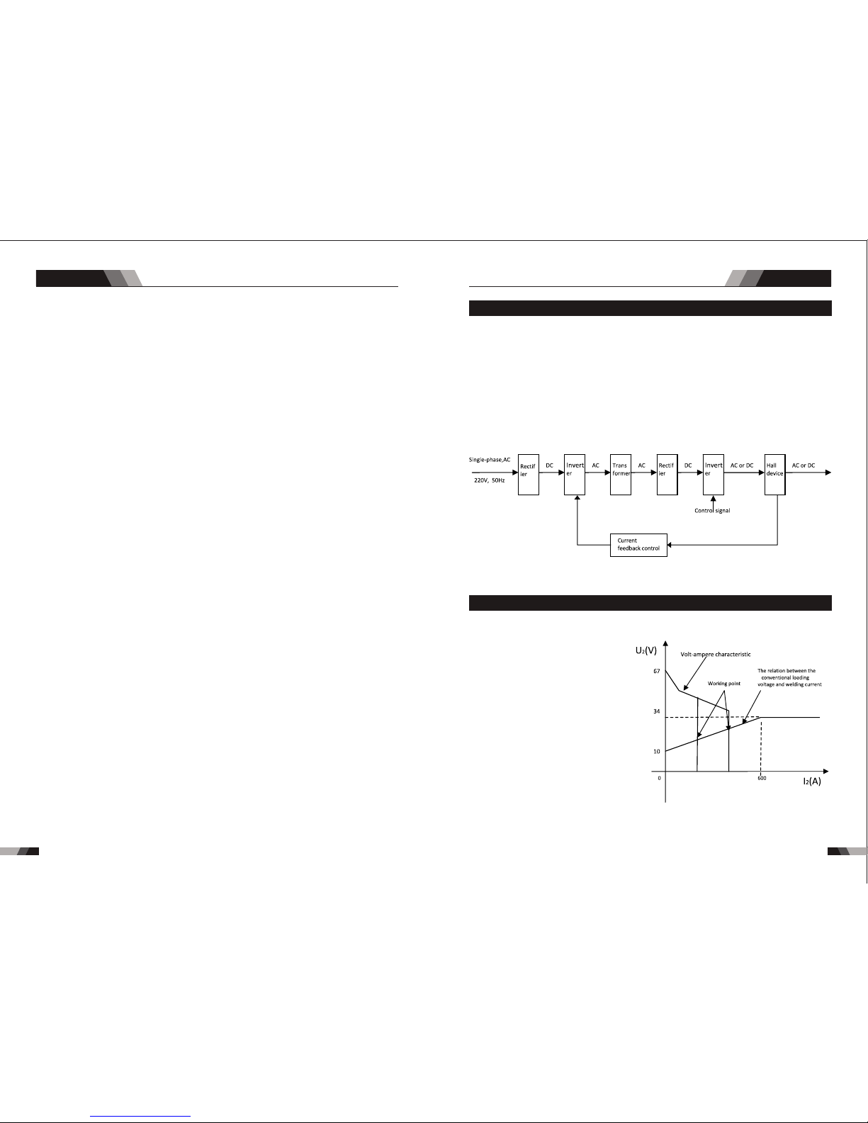
1.3 Volt - Ampere Cha racte ristic
Whe n I ≤600A , U =10 +0.04 I (V) ;
2 2 2
Whe n I >60 0A,U =34 (V).
2 2
1.2 Wor king Pr inciple
The w orki ng prin ciple o f TIG V 1841 V2 41 V341 AC /DC weldin g mach ines is sho wn as
the f ollow ing fig ure. Si ngle- phase 2 30V wor k frequ ency AC is r ectif ied int o DC (abo ut
312 V), the n is conv erted t o med ium fr eque ncy AC (ab out 20- 40KHz ) by inve rter de vice
(IG BT modu le), a fter re ducin g volta ge by med ium tra nsfor mer (th e main tr ansfo rmer) a nd
rec tifyi ng by med ium fre quenc y recti fier (f ast rec ove ry dio des) , then is o utput ted DC or AC
con tinuo usly an d stepl essly t o meet wi th the re quire ments o f weldi ng craf t.
wel ding ma chine h as an exc ellent
vol t-amp ere cha racte risti c, whos e
gra ph is sho wn as the f ollow ing
fig ure. Th e rela tion be tween t he
con venti onal ra ted loa ding vo ltage
U an d the con venti onal we lding
2
cur rent I i s as foll ows:
2
cu rrent o utp ut stab ly. M ean whi le, the w eld ing cur ren t par ame ter can b e adj usted
by se lect ing IG BT mod ule. Th e circ uit ad opts c urre nt fee dbac k cont rol te chno logy t o insu re
TI G V1 841/ V2 41/ V 341 AC/ DC
AC/DC SERIES EQUIPMENT
AC/DC SERIES EQUIPMENT
Sum mary Sum mary
111 0
1.5 Specificat ions V3 411.4 Specificat ions V1 841/V241
NO TE
Not e 1: The Ef fect ive In put Cur rent sh ould be u sed for t he dete rmina tion of c able si ze &
Not e 1: The Ef fect ive In put Cur rent sh ould be u sed for t he dete rmina tion of c able si ze &
sup ply r equi reme nts .
sup ply r equi reme nts .
Not e 2: Gene rator R equir ement s at the Ma ximum O utput D uty Cyc le.
Not e 2: Gene rator R equir ement s at the Ma ximum O utput D uty C ycle .
Not e 3: Moto r start f use s or the rmal c ircui t break ers are r ecomm ended f or this a ppl icat ion.
Not e 3: Moto r start f use s or the rmal c ircui t break ers are r eco mmen ded fo r this ap plica tion.
Che ck lo cal re quir ement s for you r sit uati on in th is rega rd.
Che ck lo cal re quir ement s for you r sit uati on in th is re gard .
Due t o varia tions t hat can o ccur in m anufa cture d produ cts, cl aimed p erfor mance , volta ges,
Due t o varia tions t hat can o ccur in m anufa cture d produ cts, cl aimed p erfor mance , volta ges,
rat ings, a ll capa citie s, meas ureme nts, di mensi ons and w eight s quote d are app roxim ate
rat ings, a ll capa citie s, meas ureme nts, di mensi ons and w eight s quote d are app roxim ate
onl y. Achieva ble ca pacitie s and ra tings in us e and op eration w ill de pend upon c orre ct
onl y. Achieva ble ca pacitie s and ra tings in us e and op eration w ill de pend upon c orre ct
ins talla tion, u se, app licat ions, m ainte nance a nd serv ice.
ins talla tion, u se, app licat ions, m ainte nance a nd serv ice.
IP2 3
IP2 3
Des cript ionDes cript ion
Wei ghtWei ght
Pow er Sour ce Dime nsion sPow er Sour ce Dime nsion s
Coo lingCoo ling
Wel der Typ eWel der Typ e
Eur opean S tanda rdsEur opean S tanda rds
Num ber of Ph asesNum ber of Ph ases
Nom inal Su pply Vol tageNom inal Su pply Vol tage
Nom inal Su pply Fr equen cyNom inal Su pply Fr equen cy
Wel ding C urrent Ran ge
(DC S TICK Mo de)
Wel ding C urren t Range
(DC S TICK Mo de)
Wel ding C urrent Ran ge
(DC T IG Mod e)
Wel ding C urren t Range
(DC T IG Mod e)
Sin gle Pha se Gene rator
Req uirem ent
Sin gle Pha se Gene rator
Req uirem ent
STI CK (MMA )
Wel ding O utput , 40ºC, 1 0 min.
STI CK (MMA )
Wel ding O utput , 40ºC, 1 0 min.
TIG ( GTAW)
Wel ding O utput , 40ºC, 1 0 min.
TIG ( GTAW)
Wel ding O utput , 40ºC, 1 0 min.
Ope n circu it volt age
Ope n circu it volt age
Pro tecti on Clas s
Pro tecti on Clas s
Max imum In put Cur rent
Max imum In put Cur rent
Effective Input Current
Effective Input Current
VEC TOR DIG ITAL V24 1 AC/ DC
21. 9 kg
H52 5mmxW 260mm xD445 mm
Fan C ooled
Inv erter P ower So urce
EN 60 974-1 / I EC 6097 4-1
1
230 V +/- 15%
50/ 60Hz
10 - 20 0A
10 - 20 0A
29. 5A
41. 7A
14. 4kVA
200 A @ 50% , 28V
141 A @ 100 %, 25. 6V
200 A @ 50% , 18V
141 A @ 100 %, 15. 6V
66V D C
IP2 3
VEC TOR DIG ITAL V34 1 AC/ DCVEC TOR DIG ITAL V18 41 AC/DC
26. 4 kg
10. 9 kg
Fan C ooledFan C ooled
Inv erter P ower So urceInv erter P ower So urce
EN 60 974-1 / I EC 6097 4-1EN 60 974-1 / I EC 6097 4-1
31
400 V +/- 15%230 V +/- 15%
50/ 60Hz50/ 60Hz
30 - 30 0A10 - 17 0A
10 - 30 0A10 - 18 0A
12. 4A
20A
17. 5A
33. 9A
18. 2KVA
11.7 KVA
300 A @ 50% , 32.0 V
212 A @ 100 %, 28. 5V
170 A @ 35% , 26. 8V
100 A @ 100 %, 24V
300 A @ 50% , 22.0 V
212 A @ 100 %, 18. 5V
180 A @ 35% , 17. 2V
107 A @ 100 %, 14. 3V
66V D C
66V D C
H52 5mmxW 260mm xD445 mmH39 5mmxW 180mm xD375 mm
AC/DC SERIES EQUIPMENT
AC/DC SERIES EQUIPMENT
Sum mary
2.1 Layout For The P anel V1 841
1312
Ope ratio n
1.6 Duty Cy cle
The r ated d uty cyc le of a Wel ding P ower So urce, i s a state ment of t he ti me it ma y be
ope rated a t its rat ed weld ing cur rent ou tput wi thout e xceed ing the t emper ature l imits o f
th e in sulat ion of t he c omp one nt p ar ts. To ex pla in t he 1 0 mi nut e du ty c ycl e perio d th e
fo llo win g exa mpl e is u sed . Sup pos e a Wel din g Pow er S our ce i s des ign ed to ope rat e at
a 50 % dut y cyc le, 300 a mpe res a t 32 vo lts . Thi s mea ns th at it has b een des ign ed an d
buil t to p rov ide the rat ed am per age ( 300 A) fo r 5 mi nut es, i.e . arc wel din g tim e, out of
ev ery 10 mi nut e per iod ( 50% o f 10 m inu tes i s 5 mi nut es) . Dur ing t he o the r 5 mi nut es of
th e 10 m inu te peri od th e Wel din g Pow er So urc e mus t id le a nd b e al low ed to cool. T he
the rmal cu t out wil l opera te if the d uty cyc le is exc eeded .
◆3M Po wer cor d
◆200 Am p elect rode ho lder wi th 3M cab le
◆200 Am p earth c lamp wi th 3M cab le
◆4M TI G Torch WP2 6
◆3M Ga s Hose
◆Ope ratin g Manua l
1.7 Packa ged Ite ms
V1841/V 241
◆3M Po wer cor d
◆300 Am p elect rode ho lder wi th 3M cab le
◆300 Am p earth c lamp wi th 3M cab le
◆4M TI G Torch WP1 8
◆3M Ga s Hose
◆Ope ratin g Manua l
V341
Duty Cyc le( PERCENTA GE)
Weldi ng Curr ent(A MPS)
10 0 12 0 14 0 16 0 18 0 2 00 2 20
0
10
20
30
40
50
60
70
80
90
10 0
24 0 26 0 28 0 30 0 32 00
Saf e Opera ting Re gion
(TI G&STI CK)
V18 41 TIG
V18 41 STIC K
Duty Cyc le( PERCENTA GE)
Weldi ng Curr ent(A MPS)
10 0 12 0 14 0 16 0 18 0 2 00 2 20
0
10
20
30
40
50
60
70
80
90
10 0
24 0 26 0 28 0 30 0 32 00
V24 1 STICK /TIG
V34 1 STICK /TIG
3
2
1
4
8
7
5
14
15
16
17
6
12
13
9
10
11
3
2
1
4
8
7
5
14
15
16
17
6
12
13
9
10
11
Saf e Opera ting Re gion
(TI G&STI CK)
1. Digit al Ammete r / Par ameter me ter
The digita l Ammeter i s used t o displ ay the a ctua l outpu t curr ent of the powe r sour ce. It is
als o used to d ispla y Param eters i n Progr ammin g Mode.
De pend ing o n the Progr amm ing Pa ram eter sele cte d, the s tatu s indi cto r adjacen t to th e
Amme ter wil l illum inate t o show th e units o f the pro gramm ing par amete r.
Whe n weldi ng, the Am meter w ill dis play ac tual we lding c urren t.
2. Power O N Ind ica tor
4. Ar cforce/Hot S tar t/Hotst art c urr ent
The PO WER ON i ndicator il lumi nates when th e ON/OF F swit ch is in th e ON pos ition a nd
Cha nge the select ed weld f uncti ons mode from we ldin g curre nt to hot start t o start t ime to
arc fo rce from the digital d ispla y.
the c orrec t mains v olt age is p rese nt.
3. Therm al Ov erl oad Indic ato r Lig ht
Thi s weld ing pow er sour ce is pro tecte d by a self r esett ing the rmost at. The i ndic ator wi ll
illumi nat e if the d uty c ycle o f the p ower s ourc e has be en ex ceed ed. S houl d the th erma l
ov erl oad indic ator i llu min ate t he output o f the po wer s our ce wi ll be d isa ble d. Once the
po wer s our ce cools down th is lig ht wi ll go O FF an d the o ver t emp era tur e con diti on wil l
au tomatic all y res et. N ote th at the m ain s pow er sw itch s houl d rem ain i n the o n posi tion
su ch that the f an con tin ues t o oper ate th us al low ing th e unit t o coo l suff icie ntl y. Do not
swi tch the u nit off s houl d a therm al over load co nditi on be pre sent.
AC/DC SERIES EQUIPMENT
AC/DC SERIES EQUIPMENT
Ope ratio n
Ope ratio n
1514
5. JOB and S AVE
You ca n pre ss JO B to se lect t he me mor y rec ord s tha t you h ave s ave d bef ore f rom 1 -9.
For t he ne w sett ing of p resen t curre nt Amp s ,jus t pres s SAVE.
6. Mode Bu tto n
Pre ss th e MODE b utto n to to ggle AC a nd DC ou tput in L IFT TIG , HF TIG .
7. Trigge r Mod e Con trol Butt on (H F TIG a nd LIFT TIG M ode o nly)
The t rig ger mo de con trol is u sed to sw itch th e funct ion alit y of the t orc h trig ger be tween
2T an d 4T.
Min imum
Cur rent
Pre ss & hold
Trig ger
Rel ease
Trig ger
No te: th at w hen op erati ng i n GT AW (HF a nd L IFT T IG m od es ), t he p ow er s ou rc e wi ll
rem ain act ivate d until t he sele cted do wn slop e time ha s elaps ed
8. Proce ss Se lec tion Butt on
Th e pro ces s sel ect ion c ont rol i s use d to se lec t the d esi red w eld ing m ode . Two mo des
are a vaila ble, GTAW ( TIG ), and M MA (Sti ck) m odes .
9. Pulse B utt on
Pre ss the PU LSE b utto n to tog gle P ulse O n and OF F.
10. Prog ram min g Paramet er In dic ators
The se ind icato r light s will il lumin ate whe n progr ammin g.
Set ting ra nges
Arcfor ce: 1-1 00AMP Hot S tart:0.1-0 .5S H otstart curr ent :1-100 AMP
Typi cally f rom 1 to 10 P PS. Pro vides a h eatin g
and c oolin g effec t on the w eld pud dle an d can
red uce dis torti on by low ering t he aver age
amp erage . Th is heat ing and c oolin g effec t also
pro duces a d istin ct ripp le patt ern in th e weld
bea d. The re lati onshi p betwe en pul se freq uency
and t ravel s peed de termi nes the d istan ce
bet ween th e rippl es. Slo w pulsi ng can al so be
coo rdina ted wit h fille r metal a dditi on and
inc rease o veral l contr ol of the w eld pud dle
In ex cess of 4 0 PPS, Pu lsed TI G beco mes mor e
aud ible th an visi ble-c ausin g incre ased pu ddle
agi tatio n for a bet ter as- welde d micro struc ture.
Pul sing th e weld cu rrent a t high sp eeds- betwe en
a hig h Peak an d a low Bac kgrou nd ampe ragecan a lso con stric t and foc us the ar c.Thi s resul ts
in ma ximum a rc stab ility, i ncre ased pe netra tion
and i ncrea sed tra vel spe eds(C ommon R ange:
100 -500 PP S).
The Ar c-Sha rpeni ng effe cts of h igh spe ed
pul sing ar e expan ded to ne w dimen sions . The
abi lity to p ulse at 5 ,000P PS furt her enh ances
arc s tabil ity and c oncen trati on pote ntial -whic h
is ex tre mel y benef icial t o autom ation w here
max imum tr avel ts peeds a re requ ired.
ou tput t o be ac tive .
Press an d hol d the to rch t rigg er to a ctiv ate th e powe r sou rce (w eld) . Rele ase t he tor ch
trigge r swi tch to c eas e weld ing .
2T N orm al M ode In th is mo de, t he to rch t rig ger mus t rem ain p res sed for the wel din g
op era tor f atigu e. I n thi s mod e th e ope rat or ca n pre ss an d re lea se t he to rch t rig ger a nd
to rch tri gger.
4T La tc h mod e th is m ode of we ld in g is ma inly u sed fo r lo ng w el din g ru ns t o re duce
th e out put wil l rem ain act ive . To d eac tiv ate t he p owe r sourc e, th e tr igg er sw itc h must
ag ain be p re ssed a nd r el eased , th us e li minat ing th e ne ed f or t he o per ato r to h old the
AC/DC SERIES EQUIPMENT
AC/DC SERIES EQUIPMENT
Ope ratio n
Ope ratio n
Lo ose wel ding te rmi nal c onn ect ion s can cau se o ver heati ng a nd re sul t in t he ma le pl ug
be ing fus ed i n the ter min al.
2.2 Control Pane l
.Gas Pre-Fl ow 1
Abs olut e sett ing r ange 0 .1s to 5 s (0. 1S inc reme nts )
Thi s param eter op erate s in TIG mo des on ly and is u sed to pr ovide g as to the w eld zon e
use d to dram atica lly red uce wel d poros ity at th e start o f a weld.
2.Init ial C urr ent
The m ain cur ren t Sett ing ra nge 1 0AMP t o 100A MP
Thi s parameter ope rates i n (4T) TIG m odes onl y and is used to set the start cu rrent f or TIG.
Th e Sta rt Cu rre nt rema ins o n un til t he torc h tri gge r swi tch i s rel eas ed af ter i t has bee n
dep resse d.
No te: T he ma xim um in iti al cu rre nt avai lab le wi ll b e lim ite d to t he se t val ue o f the bas e
cur ren t.
3.Up Slo pe
Set ting ra nges :0 .1S -10S ( 0.1S i ncr emen ts)
Thi s para mete r oper ates in (2T an d 4T) TIG modes only and is use d to set t he tim e for th e
we ld cu rre nt to ram p up, aft er th e tor ch tr igger sw itc h has b een pre sse d then re lea sed ,
fro m Initi al Curr ent to Hi gh or bas e curre nt.
4.Peak C urr ent
Set ting ra nges
V18 41: 10- 18 0A( DC TIG a nd AC HF T IG) ,10 -170A( Sti ck mod e)
Th is p ara met er sets t he TI G WE LD cu rre nt. T his p ara met er a lso set s th e ST ICK w eld
cur rent.
5.Base C urr ent
Set ting ra nges
V18 41:10 AMP to 18 0AMP ( DC TIG m ode), 10A MP to 18 0AMP ( AC HF TI G mode )
Sec ondar y curre nt (TIG )/pul se paus e curre nt.
6.Puls e Wid th
Set ting ra nges 10 %-90%
Th is pa ram ete r set s the p erc ent age o n tim e of th e PUL SE FR EQU ENC Y for H igh weld
cur rent wh en the PU LSE is ON .
7.Puls e Fre que ncy
Set ting ra nge s 1HZ -2 00HZ
Thi s param eter se ts the PU LSE F REQU ENCY w hen th e PULSE i s ON.
8.Down S lop e
Set ting ra nges 0. 1-1 0s
Thi s parameter o pera tes in TIG modes o nly and i s used to s et the time for t he weld c urre nt
to r amp d own, afte r the to rch t rig ger switc h has b een p res sed t o end c urre nt. Th is co ntro l
is us ed to eli minat e the cra ter tha t can for m at the co mpl etio n of a wel d.
9.End Cu rre nt
Set ting ra nges 10 A-180 A
This pa ramete r operate s in (4T) TIG mod es only and is us ed to set the fin ish curre nt for TIG.
The e nd current re main s ON unti l the to rch tri gger s witch is rele ased after it h as been
dep resse d.
No te: T he ma xim um crat er cu rre nt av ail abl e wil l be l imi ted t o the set v alu e of th e base
cur ren t.
10. Post F low
Set ting ra nges 1. 0-1 0S
Th is p arame te r ope rat es i n TI G modes o nly a nd is use d to ad jus t th e po st g as flow
ti me o nc e th e ar c ha s ex ti ng ui she d. T hi s co nt ro l is us ed t o dr am atic al ly r ed uc e
ox ida tio n of t he tu ngs ten e lec tro de.
171 6
17. Posi tiv e Welding Te rminal
Po sit ive W eld ing Ter min al. Wel din g cu rre nt f low s fr om th e Pow er S our ce v ia he avy
du ty ba yon et ty pe te rmi nal s. It i s ess ent ial , how eve r, th at th e mal e plu g is i nsert ed
and t urn ed sec urel y to achi eve a sou nd elec trica l conne ction .
and t urn ed sec urel y to achi eve a sou nd elec trica l conne ction .
15. Shie ldi ng Ga s Outlet
Th e Shi eld ing G as Ou tle t loc ate d on th e fro nt pa nel i s a fas t conn ecti on of a s uita ble
TIG Tor ch.
14. Nega tiv e Welding Te rminal
Ne gat ive W eld ing Te rmi nal . Wel din g cur ren t flo ws fr om th e Pow er So urce via h eav y
du ty ba yon et t ype t erm ina ls. I t is es sen tia l, ho wev er, t hat the mal e pl ug is ins ert ed
16. 5 Pin Co ntr ol So cket
The 5 pin rece ptac le is us ed to co nnec t a trig ger switch or r emot e cont rol to t he wel ding
Pow er Sour ce circ uit ry:
To make connectio ns, align ke yway, insert plug, and rota te thread ed collar fu lly clock wise.
12. Nega tiv e Con trol
13. Sele cti ng Fu nction Bu tto n
The N egat ive but ton is us ed to min us sele cted in P rogra mming s equen ce.
Thi s butt on can se lect di ffere nt pro gramm ing par amete r from No . 10
11. Posit ive C ont rol
The P osit ive but ton is us ed to plu s selec ted in Pr ogr ammi ng seq uence .
CAUTION
pr ior to s trik ing th e arc, o nce t he tor ch tr igg er swi tch h as be en pre ssed . This c ont rol is
AC/DC SERIES EQUIPMENT
AC/DC SERIES EQUIPMENT
Ope ratio n
Ope ratio n
1918
12.Wave Balance
Set ting ar range s 10%-5 0%
T hi s pa ra me te r o pe ra te s in AC T IG mo de an d i s u se d to se t t he pe ne tr at io n t o
cl ean ing act ion ra tio fo r th e AC w el d cu rr ent. G enera lly WAVE BALAN CE i s se t to
5 0% fo r AC ST IC K we ld in g. T he WAV E B AL AN CE co nt ro l c ha ng es th e ra ti o o f
pe net rat ion t o cle ani ng ac tio n of th e AC TI G wel din g arc . Max imu m wel d penet rat ion
i s ac hie ved when t he WAV E BA LANCE con tro l is s et t o 10 %. Ma xim um c lea nin g of
h ea vi ly ox id is ed a lu mi ni um o r m ag ne si um a ll oy s is ac hi ev ed wh en t he WAV E
B AL AN CE co nt ro l is se t t o 5 0%
Wid er bead , good pe netra tion
ide al for bu ildup w ork
Nar rower b ead for f illet w elds an d
aut omate d appli catio ns
Wid er bead a nd clea ning ac ting Nar rower b ead and c leani ng acti ng
AC Ba lance C ontro l
Co ntr ols a rc cl ean ing a ction. Ad jus ting the % E N of th e AC wav e cont rol s the w idth o f the
etc hing zo ne surr oundi ng the we ld.
No te : Se t the A C Ba lan ce co ntr ol f or a deq uat e ar c cl ean ing a cti on a t th e si des and in
fr ont of t he w el d pu dd le . AC B al an ce s hou ld b e fi ne t uned a cc or ding t o ho w he av y or
thi ck the ox ides ar e.
Wid er bead , good pe netra tion
ide al for bu ildup w ork
Nar rower B ead, Go od Pene trati on
Ide al For Bu ildup W ork
Wid er bead a nd clea ning ac tion Nar rower b ead, wi th no vis ible cl eanin g
2.3 Layout For The P anel V2 41/V341
10
11
12
13
14
15
9
6 78
5
4
3
2
1
16
17
18
19
20
1. RE SET B utton
Whe n softw are h as pro blem p lease t rigge r RESET b utto n.
2. Pu lse B utton
Pre ss the PU LSE b utto n to tog gle P ulse O n and OF F.
AC Fr equen cy cont rol
Con trols t he widt h of the ar c cone. I ncrea sing th e AC fr eque ncy pr ovides a mor e focu sed
arc w ith inc rease d direc tiona l contr ol.
No te : De creasi ng t he AC Fr eq ue nc y so ft en s th e ar c and b ro ade ns t he w el d pu dd le
f or a wi de r we ld b ead .
11. AC F requency
Set ting ra nges 50 HZ-20 0HZ
Th is pa rame ter op era tes i n AC TIG m ode o nly a nd is u sed t o set t he fr equency f or the
AC we ld curr ent.
3. Trigge r Mod e Con trol Butt on (H F TIG a nd LIFT TIG M ode o nly)
The t rig ger mo de con trol is u sed to sw itch th e funct ion alit y of the t orch tr igg er bet ween
2T an d 4T.
ou tput t o be ac tive .
Press an d hol d the to rch t rigg er to a ctiv ate th e powe r sou rce (w eld) . Rele ase t he tor ch
trigge r swi tch to c eas e weld ing .
2T N orm al M ode In th is mo de, t he to rch t rig ger mus t rem ain p res sed for the wel din g
AC/DC SERIES EQUIPMENT
AC/DC SERIES EQUIPMENT
Ope ratio n
Ope ratio n
No te : th at w he n op er at in g in G TAW ( HF a nd L IF T TI G mo des ), t he p ow er s ou rc e wi ll
rem ain act ivate d until t he sele cted do wn slop e time ha s elaps ed
Min imum
Cur rent
Pre ss & hold
Tri gger
Rel ease
Tri gger
4. Proce ss Se lec tion Butt on
Th e pro ces s sel ect ion c ont rol i s use d to se lec t the d esi red w eld ing m ode . Two mo des
are a vaila ble, GTAW ( TIG ), and M MA (Sti ck) m odes .
cur rent of t he po wer so urce .
At ti mes of n on-w eldi ng, t he amp erag e mete r wil l display a p re- set (p revi ew) am per age
val ue. Thi s valu e can be ad juste d by vary ing the m ultif uncti on cont rol whe n the
Pro gramm ing Par amete r Indic ator li ght sho ws BASE C URR ENT.
5. Digit al Ammete r
The digital ampe rage m eter i s used to d ispl ay bot h the pr e-set curre nt and a ctua l outp ut
6. Digit al Vol tmeter / Pa ram eter Meter
The di gita l volt me ter is us ed to dis play th e actual outp ut volt age of th e power sourc e. It is
als o used to d ispla y Param eters i n Progr ammin g Mode.
De pend ing o n the Progr amm ing Pa ram eter sele cte d, the s tatu s indi cto r adjacen t to th e
vol t meter w ill ill umina te to sho w the uni ts of the p rogra mming p arame ter.
Whe n weldi ng, the v olt met er will d ispla y actua l weldi ng volt age.
7. Power O N Ind ica tor
The PO WER ON i ndicator il lumi nates when th e ON/OF F swit ch is in th e ON position a nd
the c orrec t mains v oltag e is pres ent.
2120
Typi cally f rom 1 to 10 P PS. Pro vides a h eatin g
and c oolin g effec t on the w eld pud dle an d can
red uce dis torti on by low ering t he aver age
amp erage . Th is heat ing and c oolin g effec t also
pro duces a d istin ct ripp le patt ern in th e weld
bea d. The re lati onshi p betwe en pul se freq uency
and t ravel s peed de termi nes the d istan ce
bet ween th e rippl es. Slo w pulsi ng can al so be
coo rdina ted wit h fille r metal a dditi on and
inc rease o veral l contr ol of the w eld pud dle
In ex cess of 4 0 PPS, Pu lsed TI G beco mes mor e
aud ible th an visi ble-c ausin g incre ased pu ddle
agi tatio n for a bet ter as- welde d micro struc ture.
Pul sing th e weld cu rrent a t high sp eeds- betwe en
a hig h Peak an d a low Bac kgrou nd ampe ragecan a lso con stric t and foc us the ar c.Thi s resul ts
in ma ximum a rc stab ility, i ncre ased pe netra tion
and i ncrea sed tra vel spe eds(C ommon R ange:
100 -500 PP S).
The Ar c-Sha rpeni ng effe cts of h igh spe ed
pul sing ar e expan ded to ne w dimen sions . The
abi lity to p ulse at 5 ,000P PS furt her enh ances
arc s tabil ity and c oncen trati on pote ntial -whic h
is ex tre mel y benef icial t o autom ation w here
max imum tr avel ts peeds a re requ ired.
8. Therm al Ov erl oad Indic ato r Lig ht
Thi s weld ing pow er sour ce is pro tecte d by a self r esett ing the rmost at. The i ndic ator wi ll
illumi nat e if the d uty c ycle o f the p ower s ourc e has be en ex ceed ed. S houl d the th erma l
ov erl oad indic ator i llu min ate t he output o f the po wer s our ce wi ll be d isa ble d. Once the
po wer s our ce cools down th is lig ht wi ll go O FF an d the o ver t emp era tur e con diti on wil l
au tomatic all y res et. N ote th at the m ain s pow er sw itch s houl d rem ain i n the o n posi tion
su ch that the f an con tin ues t o oper ate th us al low ing th e unit t o coo l suff icie ntl y. Do not
swi tch the u nit off s houl d a therm al over load co nditi on be pre sent.
op era tor f atigu e. I n thi s mod e th e ope rat or ca n pre ss an d re lea se t he to rch t rig ger a nd
to rch tri gger.
4T La tc h mod e th is m ode of we ld in g is ma inly u sed fo r lo ng w el din g ru ns t o re duce
th e out put wil l rem ain act ive . To d eac tiv ate t he p owe r sourc e, th e tr igg er sw itc h must
ag ain be p re ssed a nd r el eased , th us e li minat ing th e ne ed f or t he o per ato r to h old the
AC/DC SERIES EQUIPMENT
AC/DC SERIES EQUIPMENT
Ope ratio n
Ope ratio n
Lo ose wel ding te rmi nal c onn ect ion s can cau se o ver heati ng a nd re sul t in t he ma le pl ug
be ing fus ed i n the ter min al.
1.Gas Pr e-F low
V24 1: Abso lute s etti ng ra nge 0. 1s to 20 s (0. 1S inc reme nts )
V34 1: Abso lute s etti ng ra nge 0. 1s to 20 s (0. 1S inc reme nts )
Thi s param eter op erate s in TIG mo des on ly and is u sed to pr ovide g as to the w eld zon e
use d to dram atica lly red uce wel d poros ity at th e start o f a weld.
2.4 Control Pane l
17. Posi tiv e Welding Te rminal
Po sit ive W eld ing Ter min al. Wel din g cu rre nt f low s fr om th e Pow er S our ce v ia he avy
du ty ba yon et ty pe te rmi nal s. It i s ess ent ial , how eve r, th at th e mal e plu g is i nsert ed
and t urn ed sec urel y to achi eve a sou nd elec trica l conne ction .
18. 5 Pin Co ntr ol So cket
The 5 pin rece ptac le is us ed to co nnec t a trig ger switch or r emot e cont rol to t he wel ding
Pow er Sour ce circ uit ry:
To make connectio ns, align ke yway, insert plug, and rota te thread ed collar fu lly clock wise.
20. Shie ldi ng Ga s Outlet
Th e Shi eld ing G as Ou tle t loc ate d on th e fro nt pa nel i s a fas t conn ecti on of a s uita ble
TIG Tor ch.
19. Nega tiv e Welding Te rminal
Ne gat ive W eld ing Te rmi nal . Wel din g cur ren t flo ws fr om th e Pow er So urce via h eav y
du ty ba yon et t ype t erm ina ls. I t is es sen tia l, ho wev er, t hat the mal e pl ug is ins ert ed
and t urn ed sec urel y to achi eve a sou nd elec trica l conne ction .
AC Fr equen z
Wav e Bala nce
Rem ote
ARC H otsta rt
ARC S tart Tim e
Arc force C orrec tion
AMP %
sec
AMP
%
HZ
sec
AMP %
sec
AMP %
sec
%
1
2
3
4
6
5
7
11
12
8
9
10
13
14
2.Init ial C urr ent
V241:T he ma in cur rent S ett ing ra nge 10 AMP to 2 00A MP
This parame ter oper ates in (4 T) TIG mod es only and is used to set the start curren t for TIG.
Th e Sta rt Curr ent r ema ins o n unt il th e tor ch trigg er sw itc h is rele ase d aft er it has b een
dep resse d.
No te: T he ma xim um initi al cu rre nt av ail able wil l be li mit ed to the s et va lue of the b ase
cur ren t.
3.Up Slo pe
Set ting ra nge s :0.1 S-10 S (0. 1S inc reme nts)
Thi s param eter op erate s in (2T and 4 T) TIG mod es only a nd is used t o set the ti me for th e
we ld cur rent t o ram p up, a fter t he tor ch tr igg er swi tch ha s bee n pre ssed t hen re lea sed,
fro m Initi al Curr ent to Hi gh or bas e curre nt.
4.Peak C urr ent
Set ting ra nge s
V24 1:10- 20 0A( DC TIG a nd AC HF T IG) ,10 -20 0A(S tic k mode )
V34 1:10- 30 0A( DC TIG a nd AC HF T IG) ,30 -30 0A(S tic k mode )
Th is pa ramete r set s the TIG W ELD c urrent . Thi s par ameter a lso s ets t he ST ICK wel d
cur rent.
5.Base C urr ent
Set ting ra nge s
V24 1:10A MP to 200 AMP (D C TIG mo de), 1 0AMP to 2 00AMP (AC HF TIG mode)
V34 1:10A MP to 300 AMP (D C TIG mo de), 1 0AMP to 3 00AMP (AC HF TIG mode)
Sec ondar y curre nt (TIG )/pul se paus e curre nt.
232 2
9. JOB and S AVE
You ca n pre ss JO B to se lect t he me mor y rec ord s tha t you h ave s ave d bef ore f rom 1 -9.
For t he ne w sett ing of p resen t base cu rrent Am ps ,jus t press S AVE.
10. Prog ram min g Paramet er In dic ators
The se ind icato r light s will il lumin ate whe n progr ammin g.
11. HF Butt on
Pres s and hold the HF butt on to purge the gas li ne in LIF T TIG an d HF TIG modes. To HF
the shie ldi ng gas l ine i n LIFT T IG and H F TI G mode s pre ss the H F but ton an d rele ase.
12. Mode B utt on
Pre ss th e MODE b utto n to to ggle AC a nd DC ou tput in L IFT TIG , HF TIG a nd STI CK.
13. Forw ard P rog ramming B utt on
Pre ssi ng thi s butt on will a dvanc e to the ne xt step i n the pro gramm ing seq uence .
14. Back P rog ram ming Butt on
Pre ssi ng thi s butt on will g o back to t he prev ious st ep in the p rogra mming s equen ce.
15. Posi tiv e Con trol
The P osit ive but ton is us ed to plu s selec ted in Pr ogr ammi ng seq uence ..
16. Nega tiv e Con trol
The N egat ive but ton is us ed to min us sele cted in P rogra mming s equen ce..
CAUTION
V341:T he ma in cur rent S ett ing ra nge 10 AMP to 3 00A MP
pr ior to s trik ing the arc , onc e the t orch t rigg er sw itch h as be en pr esse d. Th is con trol i s
AC Ba lance C ontro l
Co ntr ols a rc cl ean ing a ction. Ad jus ting the % E N of th e AC wav e cont rol s the w idth o f the
etc hing zo ne surr oundi ng the we ld.
No te : Se t the A C Ba lan ce co ntr ol f or a deq uat e ar c cl ean ing a cti on a t th e si des and in
fr ont of t he w el d pu dd le . AC B al an ce s hou ld b e fi ne t uned a cc or ding t o ho w he av y or
thi ck the ox ides ar e.
Wid er bead , good pe netra tion
ide al for bu ildup w ork
Nar rower B ead, Go od Pene trati on
Ide al For Bu ildup W ork
Wid er bead a nd clea ning ac tion Nar rower b ead, wi th no vis ible cl eanin g
AC/DC SERIES EQUIPMENT
AC/DC SERIES EQUIPMENT
Ope ratio n Ope ratio n
AC Fr equen cy cont rol
Con trols t he widt h of the ar c cone. I ncrea sing th e AC fr eque ncy pr ovides a mor e focu sed
arc w ith inc rease d direc tiona l contr ol.
No te: D ecr eas ing t he AC F req uen cy so fte ns the a rc a nd b roade ns th e we ld p uddle
f or a w id er w eld be ad.
Wid er bead , good pe netra tion
ide al for bu ildup w ork
Nar rower b ead for f illet w elds an d
aut omate d appli catio ns
Wid er bead a nd clea ning ac ting Nar rower b ead and c leani ng acti ng
12.Wave Balance
Set ting ar range s 10%-5 0%
11. AC F requency
Set ting ra nges 50 HZ-20 0HZ
Th is pa rame ter op era tes i n AC TIG m ode o nly a nd is u sed t o set t he fr equency f or the
AC we ld curr ent.
2524
6.Puls e Wid th
Set ting ra nges 10 %-90%
Th is para met er s ets t he pe rce nta ge on t ime of th e PUL SE FR EQU ENC Y for Hig h wel d
cur rent wh en the PU LSE is ON .
7.Puls e Fre que ncy
Set ting ra nge s 1HZ -2 00HZ
Thi s param eter se ts the PU LSE F REQU ENCY w hen th e PULSE i s ON.
8.Down S lop e
Set ting ra nges 0. 1-10s
Thi s para mete r operates in T IG modes only a nd is us ed to set t he tim e for th e weld cu rren t
to ra mp down , after t he to rch tr igge r switc h has bee n press ed to end c urren t. This c ontr ol
is us ed to eli minat e the cra ter tha t can for m at the co mpl etio n of a wel d.
10. Post F low
V24 1: Sett ing ran ges 1-2 0S
V34 1: Sett ing ran ges 1-2 0S
Th is p ara met er op era tes i n TIG mod es o nly a nd is u sed to ad jus t the pos t ga s flo w
tim e once th e arc has e xting uishe d. This c ontr ol is use d to dram atica lly red uce
oxi datio n of the tu ngste n elect rode.
Thi s para mete r oper ates i n AC TIG mo de and i s used t o set the penetrat ion to clean ing
act ion ra tio fo r the AC we ld cur rent . Gene rall y WAVE BAL ANCE i s set to 5 0% for AC
STI CK wel ding . The WAVE B ALAN CE con trol c hang es the r atio o f pene trat ion to
the WAVE BALA NCE co ntro l is set t o 10%. M axim um cle anin g of hea vily o xidi sed
alu mini um or ma gnes ium al loys i s achi eved w hen th e WAVE BAL ANCE c ontr ol is se t to
50%
9.End cu rre nt
V24 1:Set ting ra nges 10 A-200 A
Thi s parame ter ope rates in ( 4T) TIG mod es only and is used to s et the fin ish current for TI G.
The e nd curr ent rem ains ON until t he torc h trigg er swit ch is release d after i t has bee n
dep resse d.
No te: T he m axi mum c rat er cu rre nt av ail abl e wil l be li mit ed to t he se t val ue of t he ba se
cur ren t.
V34 1:Set ting ra nges 10 A-300 A
cle anin g acti on of the AC TIG weld ing ar c. Max imum we ld pen etra tion is achie ved wh en

2.5 Setup For STIC K (MMA) Welding
WAR NIN G
CA UTI ON
CA UTI ON
Be fo re c onn ectin g th e wo rk c lam p to th e wo rk a nd
in ser tin g the ele ctr ode i n the ele ctr ode h old er ma ke
sur e the mai ns powe r sup ply is s witc hed o ff.
Re mov e any p ack agi ng m ate ria l pri or to use . Do n ot
bl ock the a ir ve nts a t the f ron t or rear o f th e Wel din g
Pow er Sour ce.
Lo os e we ldi ng t erm in al c on ne ct io ns c an c aus e
ov erh eat ing a nd resu lt i n th e ma le p lug bei ng fu sed
in th e bayon et te rmin al.
AC/DC SERIES EQUIPMENT
AC/DC SERIES EQUIPMENT
Ope ratio n
Ope ratio n
27
26
pow er supp ly
2.6 Set-up For LIF T TIG (GTAW) Wel ding
WAR NIN G
Bef ore any w eldin g is to b egin , be sur e to we ar all
app ropri ate and r eco mmen ded sa fety eq uip ment .
Ant istic k
Ant istic k
U
I
13. Hot St art
14. Ar cforce Co rre cti on
Hot S tart Fu nctio n relia bly ign ites th e elect rode
and m elts pe rfect ly to ens ure the b est qua lity
eve n at the st art of th e sea m. thi s solu tion ma kes
lac k of fusi on and co ld weld s a thing o f the pas t
and s ignif icant ly redu ces wel d reinf orcem ent.
Adj ust the h ot star t curre nt here a nd the ti me here .
Dur ing the w eldin g proce ss, arc force p reven ts
t he el ec tr od e s ti ck in g in th e w el d p oo l w it h
inc rease s in curr ent. th is make s it easi er to wel d
lar ge-dr op mel ting el ectro de typ es at low curren t
str ength s with a sh ort arc i n parti cular.
Ant i-sti ck prev ents th e elect rode fr om an neal ing.
If t he el ect rod e sti cks i n sp ite of th e arc ror ce d evi ce , the
mac hi ne au to ma ti ca ll y sw it ch es o ve r t o th e mi ni mum
cu rrent wi th in a bou t 1 se co nd t o pr event th e el ect ro de
e le ct ro de a nd el ec tr od e h ol de r t o pr ot ec t th e wel de r.
Fo r Alk alin e Elec tro de, con nec t the e lec trod e hold er to t he po sit ive w eld ing termi mal
El ectr ode, please c onne ct th e ele ctrode ho lder t o the n egat ive w elding termi mal a nd
ma nufa ctur er. We ldin g curr ent f low s from the Po wer So urc e via h eavy duty b ayon et ty pe
te rmin als. I t is es sen tial, how eve r, tha t the m ale p lug i s inserte d and t urn ed se curely to
ac hiev e a soun d ele ctr ical conn ecti on. S elect STI CK mo de wi th th e pro cess sele cti on
co ntro l.
a nd c on ne ct th e wo rk le ad to th e neg at iv e w el di ng te rm in al , wh il e f or th e A ci d
con nect the wor k lead to the po sitve wel ding t ermi nal. If in d oubt c onsu lt the e lect rode
f ro m o v er h e at i ng . I n or d er to e as i ly se p ar a t e t h e
2.8 Operation No tices
◆Height a bove sea le vel is belo w 100 0m.
◆Operat ion tempe rature ra nge:-10 ˚C~ +40˚ C.
◆Relati ve humidi ty is below 9 0%( 20˚C ).
◆Prefer ably site t he machin e som e angl es ab ove th e flo or lev el, the ma xim um
angle do es not exce ed 15˚.
◆The cont ent of dust ,acid,c orrosiv e gas i n the su rro undi ng ai r or sub sta nce
can not ex ceed norm al standa rd.
◆Take care th at there is s uffi cie nt ven til atio n dur ing we ldi ng.Ther e is at least
30cm fre e disstan ce betwee n the machi ne an d wall .
2.7 Operation En viron ment
◆Read saf ty instru ction and C hap ter 1 ca ref ully b efo re att emp ting t o use t his
equipm ent.
◆Connec t the groun d wire the ma chi ne dir ect ly
◆In case cl osing the p ower swit ch, no-lo ad vo ltag e may b e expo rte d.Do n ot to uch
the outp ut electr ode with an y part of you r bod y.
◆Before o peratio n,no conc ern ed peo ple s houl d be le ft,D o not w atch t he ar c in
unprot ected eye s.
◆Ensure g ood venti lation of t he ma chin e to im prov e dut y rati o.
◆Tur n off th e engine wh en the oper ati on fin ish ed to ec ono mize e ner gy sou rce .
◆When pow er switch s huts off pr otec tiv ely be cau se of fa ilu re.Don’ t restart i t until
until pr oblem is re solved.
Otherw ise,the r ange of pro blem will b e ext ende d.
AC/DC SERIES EQUIPMENT
AC/DC SERIES EQUIPMENT
Ope ratio n Ope ratio n
2928
The f ollow ing set u p is know n as Stra igh t Pola rity o r DC elec trode p ositi ve. Thi s is
com monly u sed for D C LIFT TI G weld ing on m ost mat erial s such as s teel an d stain less
ste el.
1. Sw itch th e ON/OF F Swi tch (l ocat ed on t he rea r pane l) to OFF.
2. Co nnect t he work l ead cab le to the p ositi ve outp ut term inal, a nd the LI FT TIG Torch
cab le to the n egati ve outp ut term inal.
3. Co nnect t he gas li ne/ho se to the p roper s hield ing gas s ource .
4. Sl owly op en the Arg on Cyli nder Val ve to th e fully o pen positi on.
5. Co nnect t he work l ead cla mp to you r work pi ece.
6. Th e tung sten mu st be gro und to a bl unt poi nt (sim ilar to a p encil ) in orde r to achi eve
opt imum we lding r esult s. See il lustr ation . It is cri tic al to gr ind th e tun gste n elec trode
in th e direc tion th e grind ing whe el is tur ning. G rind at a 3 0 degre e angle a nd neve r
to a sh arp poi nt.
7. In stall t he tung sten wi th appr oxima tely 1. 6mm to 3. 2mm s tick ing ou t from th e
gas c up, ens uring y ou have c orrec t sized c ollet .
8. Tig hten th e back ca p.
9. Tur n the swi tch to th e “ON” po sitio n. The po wer L. E.D. li ght sho uld ill umina te.
10. S et the we lding p roces s to LIFT T IG.
11. Se t the We ld Cur rent Co ntrol K nob to th e desir ed ampe rage.
12. You are no w read y to begin LI FT TIG We lding.
pow er supp ly
Ar./ GAS(T IG/WI G)
TIG torc h
NO TE
3130
3.1 Troubleshoo ting
◆Bef ore arc w eldin g machi nes are d ispat ched fr om the fa ctory, t hey ha ve alre ady bee n
deb ugged a ccura tely. So f orbi d anyon e who is no t autho rized b y us to do an y chang e to
the e quipm ent!
◆Mai ntena nce cou rse mus t be oper ated ca reful ly. If any w ire be comes f lexib le or is
mis place d, it may be pote ntial d anger t o user!
◆Onl y profe ssion al main tenan ce pers onal wh o is auth orize d by us cou ld overhau l the
mac hine!
◆Gua rante e to shut o ff the ar c weld ing mac hine’ s power bef ore tu rn on the out line o f
the e quipm ent!
◆If th ere is an y probl em and ha s no the au thori zed pro fessi onal ma inten ance pe rsona l,
ple ase con tact lo cal age nt or the b ranch c ompan y!
If th ere a re som e simp le tr oubl es of V-s eries w eldin g machi ne, you c an cons ult the
fol lowin g overh aulin g chart :
Nr.
Nr.
1
7
8
9
10
11
2
3
4
5
6
Troubles
Troubles
AC/DC SERIES EQUIPMENT
AC/DC SERIES EQUIPMENT
Tro ubles hooti ng Tro ubles hooti ng
Solution
Solution
Fan is broken
The welding cable is not connected
with the two output if the welder
Connect the welding cable to
the welder's output
The power board is broken
The power cable is broken
There is something in the fan
The welding cable is damaged
The earth cable connected unstably
The welding cable is too long
Input voltage not stable
There is oil or dust on the workpiece
Gas cylinder is close or gas
pressure is low
The HF igniting board does not work
Something is in the valve
Check if the function selected MMA
Change the function to TIG
Check the HF funtion is selected Select the HF funtion
HF board is broken
Earth clamp connect not stable
Repair or change it
Check the earth clamp
Open or change the gas cylinder
Remove it
Remove it
Change it
Change it
Change it
The distance between discharge r is
too short or too long
The malfunctio n of the welding gun
switch
No argon gas flow or the air tube
connect not good
No argon gas flow or the air tube
connect not good
Pressure too high or air regulator is
broken
There is no Argon flow or the
connectio n is poor
The distance between tungsten
electrode and workpiece is too long
Repair or change it
Check the earth cable
Use an appropriate welding cable
Check the power supply
Check and remove it
Reduce the distance
(about 3mm ,less than 5mm)
Check and reconnect
Repair or change it
Adjust the distance (about 0.8mm)
Check the welding torch switch,
control cable and aero socket.
Check and reconnect
Check and reconnect
Check gas
The start capacitor of fan damaged
Tur n on the p ower
sou rce, po wer
ind icato r is lit, f an
is no t worki ng.
Arc c an not be
ign ited (T IG) ,
the re is spa rk
on th e HF
ign iting b oard
Arc c an not be
ign ited (T IG) ,
the re is no sp ark
on th e HF
ign iting b oard
Tur n on the
pow er sour ce,
eve rythi ng is
nor mal , but n o
HF ig nitin g
No ga s flow (T IG)
Gas a lways f lows
Tur n on the
pow er sour ce,
fan i s worki ng,
pow er indi cator
is no t lit
Tur n on the p ower
sou rce, fa n is not
wor king ,p ower
ind icato r is not li t
Tur n on the p ower
sou rce, po wer
ind icato r is lit, f an
is wo rking , there
is no w eldin g
out put.
The n umber o f the
dis play is n ot
int act
No no -load
vol tage ou tput
(MM A)
Reasons
Reasons
Cha nge fan
Cle an it
Cha nge cap acito r
The p ower li ght dam aged or
con necti on is not g ood
The p ower ca ble con necte d not
goo d
Con trol bo ard is br oken
st
1 in verte r circu it dama ged
nd
2 fee dback c ircui t is faul t
Dig ital tu be is bro ken
The d ispla y panel i s damag ed
If th e overh eat ind icato r is on
The m ain cir cuit is b roken
The m achin e is brok en
Cha nge the d ispla y panel
Display panel is broken
The light of the power indicator is
broken and the problems
mentioned in Nr. 2
Change the light of the power
indicator or refer to the solution
in Nr. 2
Cha nge it
Cha nge it
Cha nge it
Cha nge it
Rep air or ch ange it
Cha nge the p ower li ght
Con nect co rrect ly
Pow er on swi tch is da maged
The p ower bo ard is br oken
Cha nge it
Rep lace it
Cha nge it
Cha nge it
Wait a few minutes, the machine
can b e opera ted nor mal
Che ck and re pair
Con sult th e deale r or the
man ufact urer
Elec tromagn etic valv e is damaged
Air tub e is brocken
Some thing is in the va lve
Elec tromagn etic valv e is damaged
3332
AC/DC SERIES EQUIPMENT
Tro ubles hooti ng
STICK SERIES EQUIPMENT
CHAPTER 2
STICK SERIES EQUIPMENT
E-S eries
Nr.
16
17
18
Troubles
Solution
Over-heat prot ection ,too much
welding curren t
Reduce the welding current
Reduce the welding time
Over-heat prot ection ,working too
much time
Over-curr ent protection, current in
the main circuit is out of control
Tig torch is connected to the
positive termi nal
Tungsten electrod e is too big for
the welding current
Check the earth clamp position on
the work piece
Check and repair main circuit
and drive board
Connect the tig torch to negative
terminal
Adjust the position of earth clamp
Select the correct size of tungsten
electrode
Thermal overload
indicator light is on
Tig electrode melts
when welding
Arc flutters during
Tig welding
Reasons
15
The p enetr ation
of mo lten po ol is
not e nough
Adj ust the d istan ce from t orch
to wo rk piec e
Use t he suit able le ngth fr om
man ufact urer
Inc rease t he weld ing cur rent
The w eldin g curre nt is adj usted
too l ow
The a rc is too l ong in th e weldi ng
pro cess
The p ower ca ble or th e weldi ng
cab le is too l ong
12
Checking if the electorde stick to
the work piece that the anti-stick
function is on
Repair or change it
Repair or change it
Change to suitable setting
The w eldin g
cur rent ca nnot
be ad juste d
Cont rol board is br oken
Cont rol board is br oken
AC Width adjustment is not correct
Shut off the power when changing the tor ch
Sep arate t he elec trode a nd
wor k piece
13
14
Repair or change it
Check the power supply
Change the fan
Change it
Change it
No AC ou tput
whi le sele cting
"AC "
The w eldin g
cur rent di splay ed
isn 't acco rdant
wit h the act ual
val ue
The pow er board is bro ken
Inpu t voltage is to o low
Fan is bro ken
The AC drive boar d damaged
The AC IGBT/IGBT module damaged
The m in valu e displ ayed is n't
acc ordan t with th e actua l value
Adj ust pot entio meter I min on
the c ontro l board
Adj ust pot entio meter I min on
the c ontro l board
The m ax valu e displ ayed is n't
acc ordan t with th e actua l value
◆
occ oure d, the a larm la mp on th e fron t panel will be o n and th e outpu t curr ent wi ll
be cu t off. It can sel f-pr otec t and pr olong the usi ng lif e.
In tel li gen t pr ote cti on: o ver -cu rr ent , ov er- hea t, wh en t he m ent ion ed pr obl ems
3534
STICK SERIES EQUIPMENTSTICK SERIES EQUIPMENT
Sum mary
Sum mary
1.1 Brief I ntrod uctio n
E16 1, E201 , E221, E 301 , E401 w eldi ng mach ines ad opts th e lat est pu lse wi dth
mod ulati on (PWM ) techn ology a nd insu lated g ate bip olar tr ansis tor (IG BT) pow er modu le,
whi ch can ch ange wo rk freq uency t o mediu m frequ ency so a s to repl ace the t radit ional
hul king wo rk freq uency t ransf ormer w ith the c abine t mediu m frequ ency tr ansfo rmer. Th us,
its c harac teriz ed with p ortab le, sma ll size , light w eight , low con sumpt ion and e tc.
E16 1,E20 1,E22 1,E30 1,E40 1 STICK m achin es Char acter istic s:
◆MCU c ontro l syste m, resp onds im med iate ly to an y cha nges .
◆hi gh vo lta ge f or a rc igni ti ng to ens ure t he su cce ss r at io of ign iti ng a rc.
◆Lif t TIG ope rat ion, I f the tu ngs ten el ectr ode t ouch es the w ork piec e when w eld ing,
the c urren t will dr op to s hort -cir cui t curr ent to p rot ect tu ngst en.
◆Ped al cont rol the w eld ing cu rren t.
◆IN DC T IG oper ati on ele ctro de to uche s the wo rkp iece w hen we ldi ng, th e curr ent
wil l dro p to sho rt-c irc uit cu rren t to pr otec t tung ste n.
◆
pie ce more t han 2 sec onds, t hus t he out put cu rre nt com e down t o aro und 20 A in
ord er to eas ily sep erate t he elec trode a nd el ectr ode ho lde r to pro tect t he we lder .
1.3 Specificat ions E1 61/E201
IP2 3
Des cript ion
Wei ght
Pow er Sour ce Dime nsion s
Coo ling
Wel der Typ e
Eur opean S tanda rds
Num ber of Ph ases
Nom inal Su pply Vol tage
Nom inal Su pply Fr equen cy
Wel ding C urrent Ran ge
( STI CK Mode )
Sin gle Pha se Gene rator
Req uirem ent
STI CK (MMA )
Wel ding O utput , 40ºC, 1 0 min.
Ope n circu it volt age
Pro tecti on Clas s
Max imum In put Cur rent
Effective Input Current
VEC TOR DIG ITAL E20 1 STICK
10 kg
H39 0mmxW 180mm xD390 mm
Fan C ooled
Inv erter P ower So urce
EN 60 974-1 / I EC 6097 4-1
1
230 V +/- 15%
50/ 60Hz
20 - 20 0A
22. 8A
41. 7A
14. 4kVA
200 A @30 %, 28V
110A @ 10 0%, 24 .4V
66V D C
IP2 3
VEC TOR DIG ITAL E16 1 STICK
9.6 kg
Fan C ooled
Inv erter P ower So urce
EN 60 974-1 / I EC 6097 4-1
1
230 V +/- 15%
50/ 60Hz
10 - 16 0A
19. 8A
31. 4A
10. 8KVA
160 A @ 40% , 26. 4V
101 A @10 0%, 24 V
66V D C
H39 0mmxW 180mm xD390 mm
NO TE
Due t o variation s that c an occu r in man ufac tured p rodu cts, claime d perf orma nce, vo ltag es,
rat ings , all cap acit ies, measur emen ts, di mensi ons an d weig hts quo ted ar e approxima te
onl y. Ach ievable cap acit ies and ratin gs in use and ope rati on will d epen d upon co rrec t
ins tall atio n, use, a ppli cati ons, ma inte nanc e and ser vice .
◆200 Am p elect rode ho lder wi th 3M cab le
◆200 Am p earth c lamp wi th 3M cab le
◆3M Po wer cab le
◆Ope ratin g Manua l
1.4 Packa ged Ite ms
E161/E2 01
1.2 Wor king Pr inciple
230V
The w orki ng prin ciple o f E161/ E201/ E221/ E301/ E401 we lding m achin es is sho wn as
the f ollow ing fig ure. Si ngle- phase 2 30V wor k frequ ency AC is r ectif ied int o DC(ab out
312 V ), then i s conve rted to m edi um fre quen cy AC (abo ut 20-4 0KHz) b y inver ter dev ice
(IG BT modu le), a fter re ducin g volta ge by med ium tra nsfor mer (th e main tr ans form er) an d
Mea nwhil e, the we lding c urren t param eter ca n be adju sted co ntinu ously a nd step lessl y
to me et the re quire ments o f weldi ng craf t.
Ant i-Sti ck func tio n auto mati cal ly app eare d whe n the el ectr ode s tick t o the wo rk
re ctifyin g by me dium f req uen cy re ctif ier (f ast r eco ver y dio des) ,the n is ou tpu tte d DC .T he
ci rc ui t ad op ts c ur re nt f ee db ac k co nt ro l te ch no log y to in su re cu rr en t ou tp ut s ta bl y.
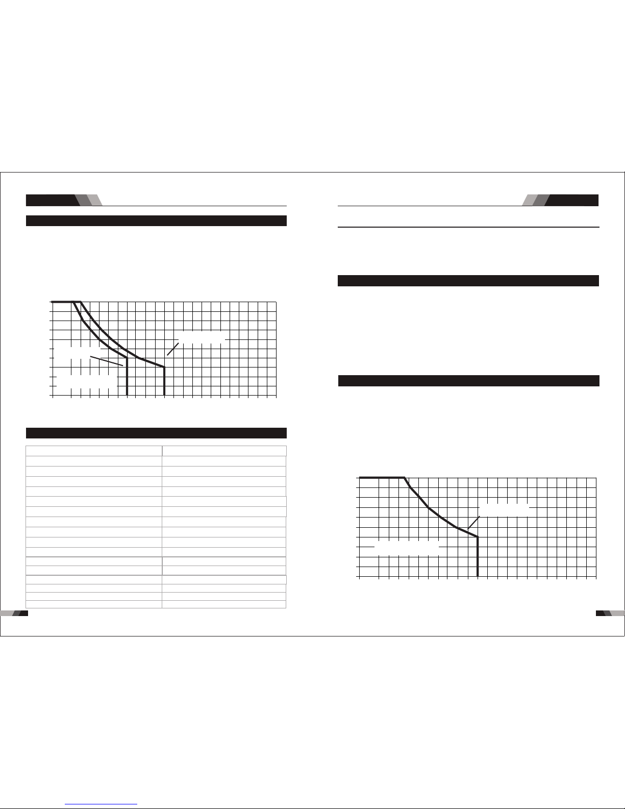
3736
1.5 Duty Cy cle
The r ated d uty cyc le of a We ldi ng Pow er Sou rce is a st ateme nt of the t ime i t may be
ins ulati on of the c ompon ent par ts. To expl ain th e 10 minu te duty c ycle pe riod th e follo wing
exa mple is u sed. Su ppose a W eldi ng Powe r Sourc e is desi gned to oper ate at a 4 0% duty
cyc le, 200 a mpere s at 28 vol ts. Thi s mean s that it h as been d esign ed and bu ilt to pr ovide
the r ated am perag e (200A ) for 4 min ute s, i.e . arc we ldi ng tim e, out o f eve ry 10 mi nute
the W eldi ng Powe r Sourc e must id le and be a llowed to co ol.
STICK SERIES EQUIPMENTSTICK SERIES EQUIPMENT
Duty Cyc le(P ERC ENTAG E)
Welding Cu rrent(AM PS)
10 0 120 14 0 160 18 0 20 0 22 0
0
10
20
30
40
50
60
70
80
90
10 0
24 0 2 60 28 0 3 00 3 200
E20 1 STICK
E16 1 STICK
Saf e Opera ting Re gion
(ST ICK)
ope rate d at its r ated w eldi ng cur rent o utput without exc eedi ng the t empe ratu re lim its of t he
per iod (4 0% of 10 mi nute s is 4 minu tes) . Duri ng the other 6 mi nute s of the 10 m inut e period
1.8 Duty Cy cle
The r ated d uty cyc le of a We ldi ng Pow er Sou rce is a st ateme nt of the t ime i t may be
ins ulati on of the c ompon ent par ts. To expl ain th e 10 minu te duty c ycle pe riod th e follo wing
exa mple is u sed. Su ppose a W eldi ng Power Sou rce is d esigned t o oper ate at a 40% du ty
the r ated am perag e (200A ) for 4 min ute s, i.e . arc we ldi ng tim e, out o f eve ry 10 mi nute
the W eldi ng Powe r Sourc e must id le and be a llowed to co ol.
Duty Cyc le( PERCENTA GE)
Weldi ng Curr ent(A MPS)
10 0 12 0 14 0 16 0 18 0 2 00 2 20
0
10
20
30
40
50
60
70
80
90
10 0
24 0 26 0 28 0 30 0 32 00
E22 1 STICK /TIG
Saf e Opera ting Re gion
(TI G&STI CK)
ope rate d at its r ated w eldi ng cur rent o utpu t with out ex ceed ing th e temp erat ure li mits o f the
cy cle, 200 a mper es at 28 v olts . Thi s mea ns th at it h as be en de sign ed and b uilt t o pro vid e
per iod (4 0% of 10 minute s is 4 min utes ). Dur ing the other 6 m inut es of the 10 minu te per iod
1.7 Packa ged Ite ms
◆200 A ele ctrod e holder wit h 3M cab le.
◆200 A ear th clam p with 3M c able
◆4M TI G Torch WP2 6
◆3M Po wer cab le
◆Ope ratin g Manua l
E221
NOTE
Due t o varia tion s that can occu r in manu fact ured p roduc ts, cl aimed perfo rman ce, vol tage s,
rat ings , all cap acit ies, me asur ements, dim ensi ons and w eigh ts quot ed are a pproximat e
onl y. Ach ievab le cap acities and r atin gs in use a nd oper atio n will de pend u pon correct
ins tall ation, use, a pplicatio ns, ma intenance a nd service.
Wel ding O utput , 40ºC, 1 0 min. TI G
200 A @ 40% , 18V 12 6A @ 100%,15 V
Des cript ion
Wei ght
Pow er Sour ce Dime nsion s
Coo ling
Wel der Typ e
Eur opean S tanda rds
Num ber of Ph ases
Nom inal Su pply Vol tage
Nom inal Su pply Fr equen cy
Wel ding C urren t Range ( STIC K/ TIG M ode)
Sin gle Pha se Gene rator R equir ement
Wel ding O utput , 40ºC, 1 0 min. ST ICK (MM A)
Max imum In put Cur rent
Effective Input Current
VEC TOR DIG ITAL E22 1 STICK
10. 59 k g
Fan C ooled
Inv erter P ower So urce
EN 60 974-1 / I EC 6097 4-1
1
230 V +/- 15%
50/ 60Hz
10 - 20 0A/5- 170A
26. 3A
41. 7 A
14. 4KVA
200 A @ 40% , 28V 12 6A @ 100%, 25V
H39 0mmxW 180mm xD390 mm
Ope n circu it volt age
66V D C
IP2 3
Pro tecti on Clas s
1.6 Specificat ions E2 21
Sum mary Summa ry
38
39
Sum mary Summa ry
STICK SERIES EQUIPMENTSTICK SERIES EQUIPMENT
2.1 Layout For The P anel E1 61 /E201
11
22
88
66
33
44
55
77
1.11 Duty Cy cle
The r ated d uty cyc le of a We ldi ng Pow er Sou rce is a st ateme nt of the t ime i t may be
ins ulati on of the c ompon ent par ts. To expl ain th e 10 minu te duty c ycle pe riod th e follo wing
exa mple is u sed. Su ppose a W eldi ng Powe r Sourc e is designe d to ope rate at a 60% d uty
the r ated am perag e (400A ) for 6 min utes, i .e. a rc wel ding t ime , out of e very 1 0 min ute
per iod (60 % of 10 min utes is 6 m inute s).Du ring th e other 4 m inute s of the 10 m inute p eriod
the W eldi ng Powe r Sourc e must id le and be a llowed to co ol.
ope rate d at its r ated w eldi ng cur rent output without exc eedi ng the t empe ratu re lim its of t he
cy cle, 400 a mper es at 36 v olts . Thi s mea ns th at it h as be en de sign ed and b uilt t o pro vid e
Duty Cyc le( PERCENTA GE)
Weldi ng Curr ent(A MPS)
10 0 13 0 160 1 90 2 20 250 2 80
0
10
20
30
40
50
60
70
80
90
10 0
310 3 30 3 60 3 90 4 200
E40 1 STICK
E30 1 STICK
Saf e Opera ting Re gion
(ST ICK)
1.10 Pack aged It ems
◆300 A ele ctrod e holder wit h 3M cab le
◆300 A ear th clam p with 3M c able
◆3M Po wer cab le
◆Ope ratin g Manua l
E301/E401
1.9 Specificat ions E3 01/E401
IP2 3
Des cript ion
Wei ght
Pow er Sour ce Dime nsion s
Coo ling
Wel der Typ e
Eur opean S tanda rds
Num ber of Ph ases
Nom inal Su pply Vol tage
Nom inal Su pply Fr equen cy
Wel ding C urrent Ran ge
( STI CK Mode )
Sin gle Pha se Gene rator
Req uirem ent
STI CK (MMA )
Wel ding O utput , 40ºC, 1 0 min.
Ope n circu it volt age
Pro tecti on Clas s
Max imum In put Cur rent
Effective Input Current
VEC TOR DIG ITAL E40 1 STICK
26. 3 kg
H54 0mmxW 235mm xD445 mm
Fan C ooled
Inv erter P ower So urce
EN 60 974-1 / I EC 6097 4-1
3
400 V +/- 15%
50/ 60Hz
30 - 40 0A
20. 4A
26. 3A
27. 3kVA
66V D C
IP2 3
VEC TOR DIG ITAL E30 1 STICK
19. 2 kg
Fan C ooled
Inv erter P ower So urce
EN 60 974-1 / I EC 6097 4-1
3
400 V +/- 15%
50/ 60Hz
30 - 30 0A
13. 6A
17. 5 A
18. 2KVA
66V D C
H51 5mmxW 224mm xD375 mm
300 A @ 60% , 32V
232 A @ 100 %, 29. 3V
400 A @ 60% , 36V
310 A @ 100 %, 32. 4V
Due t o varia tions t hat can o ccur in m anufa cture d produ cts, cl aimed p erfor mance ,volt ages,
rat ings, a ll capa citie s, meas ureme nts, di mensi ons and w eight s quote d are app roxim ate
onl y. Achi evable cap acit ies and rat ings i n use and ope rati on will dep end up on correc t
ins talla tion, u se, app licat ions, m ainte nance a nd serv ice.
40
41
Ope ratio n
STICK SERIES EQUIPMENTSTICK SERIES EQUIPMENT
1. Power I ndi cat or
The g reen p ower indica tor wi ll be il lumi nated when th e weld er is turned ON a nd ind icat es
the p rese nce of po wer.
DO NO T TOU CH the e lectrod e wire w hile it is be ing fe d through t he sys tem. The electr ode
wir e will be a t weldi ng volt age pot entia l.
WAR NIN G
2. Therm al Ov erl oad Indic ato r Lig ht
Thi s weld ing pow er sour ce is pro tecte d by a self r esett ing the rmost at. The i ndic ator wi ll
illumi nat e if the d uty c ycle o f the p ower s ourc e has be en ex ceed ed. S houl d the th erma l
ov erl oad indic ator i llu min ate t he output o f the po wer s our ce wi ll be d isa ble d. Once the
po wer s our ce cools down th is lig ht wi ll go O FF an d the o ver t emp era tur e con diti on wil l
au tomatic all y res et. N ote th at the m ain s pow er sw itch s houl d rem ain i n the o n posi tion
su ch that the f an con tin ues t o oper ate th us al low ing th e unit t o coo l suff icie ntl y. Do not
swi tch the u nit off s houl d a therm al over load co nditi on be pre sent.
2.2 Layout For The P anel E2 21
11
22
3
10
11
5
4
7
6
9
8
1. Power I ndi cat or
The g reen p ower i ndic ator w ill be i llum inat ed when the wel der is t urne d ON and i ndic ates
the p rese nce of p ower.
3.Digi tal D isp lay
The digi tal m eter i s used t o display t he pr e-se t (pr eview) am per age fo r wel ding, the
preset p ara mete rs in H ot st art, s tar t time a md Arc fo rce a nd act ual w eldi ng amp erag e of
the powe r sou rce wh en wel ding .
4.Sele cti ng Fu nction Bu tto n
Pre ss and re lease t his but ton to ch ange th e selec ted wel d funct ions mo de from w eldin g
cur rent to h otsta rt to sta rt ti me to ARC F orce f rom t he dig ital d isp lay.
5.Posi tiv e Con trol
The p ositi ve cont rol is us ed to plu s setti ng para meter f or sele cted fu nctio n from 4.
6.Nega tiv e Con trol
The n egati ve cont rol is us ed to min us sett ing par amete r for sel ected f uncti on from 4 .
7. Negat ive W elding Ou tpu t Termi nal
The n egati ve weld ing ter minal i s used to c onnec t the wel ding ou tput of t he powe r sourc e
to th e appro priat e weldi ng acce ssory s uch as el ectro de hold er. It is es senti al, how ever,
tha t the mal e plug is i nse rted a nd tur ned s ecur ely to a chiev e a sound e lec tric al
con necti on.
CA UTI ON
DO NO T TOU CH the e lectrod e wire w hile it is be ing fe d through t he sys tem. The electr ode
wir e will be a t weldi ng volt age potent ial.
Loo se weld ing ter minal c onnectio ns can c ause over heat ing and res ult in t he male plu g
bei ng fuse d in the ba yonet t ermin al.
8. Posit ive W elding Ou tpu t Termi nal
The p ositive w eldi ng ter mina l is use d to con nect t he weldin g outp ut of th e powe r sour ce
to th e appr opr iate w eldi ng acc esso ry suc h as ear th clamp. I t is ess enti al, ho weve r, that
the m ale pl ug is inser ted an d turn ed sec urel y to ach ieve a soun d elec tric al con nect ion.
2. Therm al Ov erl oad Indic ato r Lig ht
Thi s weld ing pow er sour ce is pro tecte d by a self r esett ing the rmost at. The i ndic ator wi ll
illumi nat e if the d uty c ycle o f the p ower s ourc e has be en ex ceed ed. S houl d the th erma l
ov erl oad indic ator i llu min ate t he output o f the po wer s our ce wi ll be d isa ble d. Once the
po wer s our ce cools down th is lig ht wi ll go O FF an d the o ver t emp era tur e con diti on wil l
au tomatic all y res et. N ote th at the m ain s pow er sw itch s houl d rem ain i n the o n posi tion
su ch that the f an con tin ues t o oper ate th us al low ing th e unit t o coo l suff icie ntl y. Do not
swi tch the u nit off s houl d a therm al over load co nditi on be pre sent.
Set ting ra nges
Arcfor ce: 1-1 00AMP Hot S tart:0.1-0 .5S H otstart curr ent :1-100 AMP
WAR NIN G
Ope ratio nOpe ratio n
 Loading...