

Page 1

VECTORQUADS
VTC250 ASSEMBLY MANUAL
Product ID. : VTC250
Ver. : 1.00
Page 2
VECTORQUADS
Introduction
The VTC250 tricopter features a simple tilting rotor design allowing level forward flight. In addition
to the supplied hex keys, you will need a Phillips screw driver during this build. It is recommended
you use blue loctite (or equivalent product) on all screws inserted into metal parts only. Do not
use any thread locking substances on any of the plastic parts.
Parts List
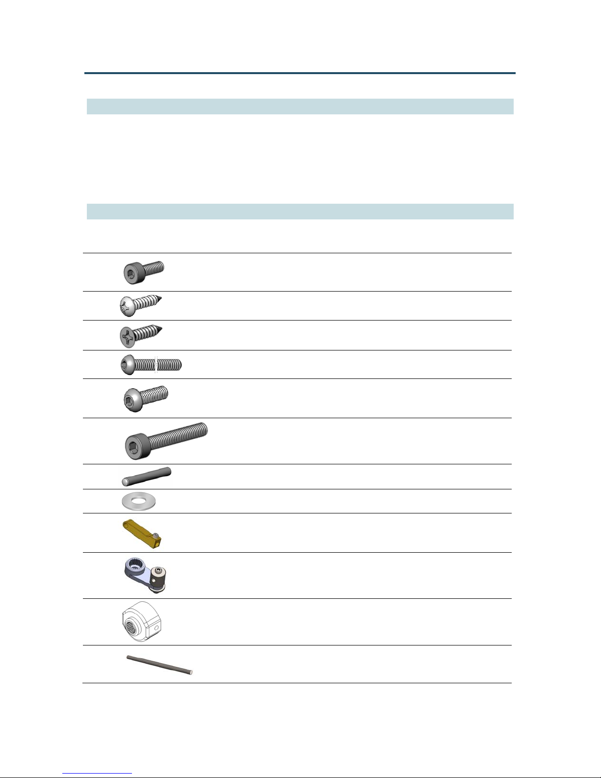
4 x
4 x
4 x
3 x
12 x
6 x
1 x
12 x
1 x
Socket Head Cap Screw M2x0.4x6
Pan Head Phillips Screw 9mm Length
Flat Head Phillips Screw 9mm Length
Button Head Cap Screw M2x0.4x18
Button Head Socket Cap Screw M2.5x0.45x8
Socket Head Cap Screw M2.5x0.45x16
Alloy Steel Dowel Pin M2x16
Flat Washer
Rod End
1 x
1 x
1 x
Servo Horn & Linkage Stopper Assembly
Servo Tube Hub
Short Push Rod
Page 3
VECTORQUADS
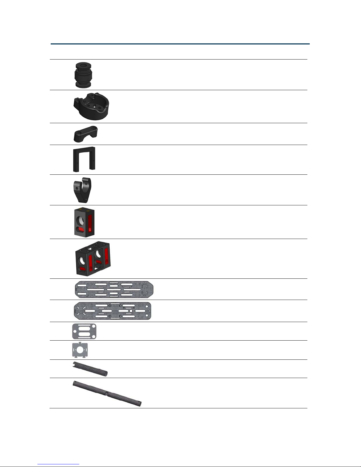
3 x
3 x
3 x
2 x
2 x
1 x
Vibration Dampening Rubber Ball
Motor Mount
Motor Mount Clamp
Servo Mount Frame
Tube Clamp
Tail Tube Pivot Block
1 x
1 x
1 x
1 x
1 x
1 x
1 x
Tube Pivot Block
Base Plate
Top Plate
HD Camera Plate
FPV Camera Plate
12mm Tail Tube
12mm Tube
Page 4
VECTORQUADS
Pivot T ube Assem bly
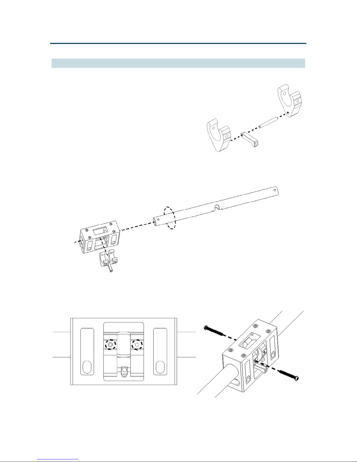
1. Slide the Alloy Steel Dowel Pin M2x16 onto the
Rod End. Insert the Alloy Steel Dowel Pin M2x16
into the holes on the Tube Clamps as shown.
2. Position the Tube Clamp assembly within the Tube Pivot Block and push the 12mm Tube
through the holes using a twisting motion.
3. Align the holes on the tube with the threaded holes on the clamps and use two Button Head
Cap Screws M2x0.4x18 to secure the tube in place.
Page 5
VECTORQUADS
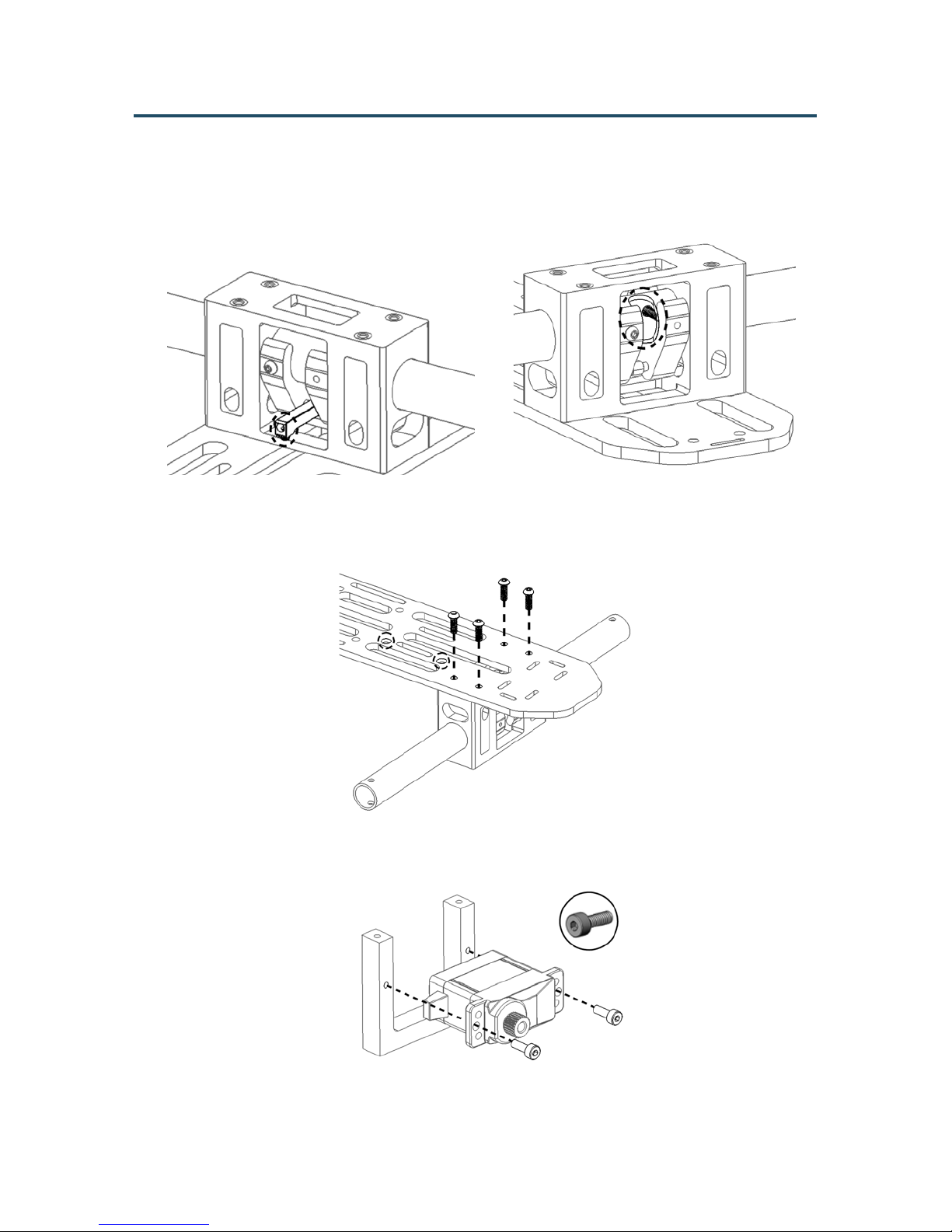
4. Make sure the rod ends are pointing towards the center of the base plate and the cutout on
the tubes on the opposite side towards the ends.
Mount the tube assembly onto the Base Plate using four Button Head Socket Cap Screw
M2.5x0.45x8 on the same side as the countersunk holes. Note the orientation of the tube
pivot block with respect to the base plate.
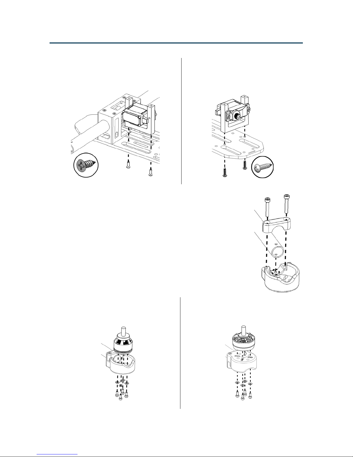
5. Secure the two servos on the Servo Mount Frames using two Socket Head Cap Screw
M2x0.4x6.
Page 6
VECTORQUADS
6. Mount the Servo Mount Frame onto the
base plate using two Flat Head Phillips
Screw 9mm Length. Do not over tighten
screws.
8. Assemble the Motor Mount onto the ends of the tubes using a Motor
Mount Clamp and two Socket Head Cap Screw M2.5x0.45x16. Align
the locating pins on the clamp and mount to the guide holes on the tube.
7. Mount the tail Servo Mount Frame onto
the base plate using two Pan Head
Phillips Screw 9mm Length. Do not
over tighten screws.
IMPORTANT: Do not completely tighten one screw, then the other.
Tighten each screw a little at a time to avoid putting too much stress on
one side of the tube. Tighten screws just enough to remove any play on
the motor mount.
Note that due to the tube length and frame size, 5 inch props are the
max size that can be used with this frame.
Do not install motors at this time. Simply choose the orientation of the
motor mounts based on the intended motor size you plan to use.
For 1806 18mm diameter motors, install
inside the motor mount. Use supplied
washers with screws to mount the motors.
For a stator diameter larger than 18mm,
rotate the motor mount upside down and
install motors on the bottom side.
Page 7
VECTORQUADS
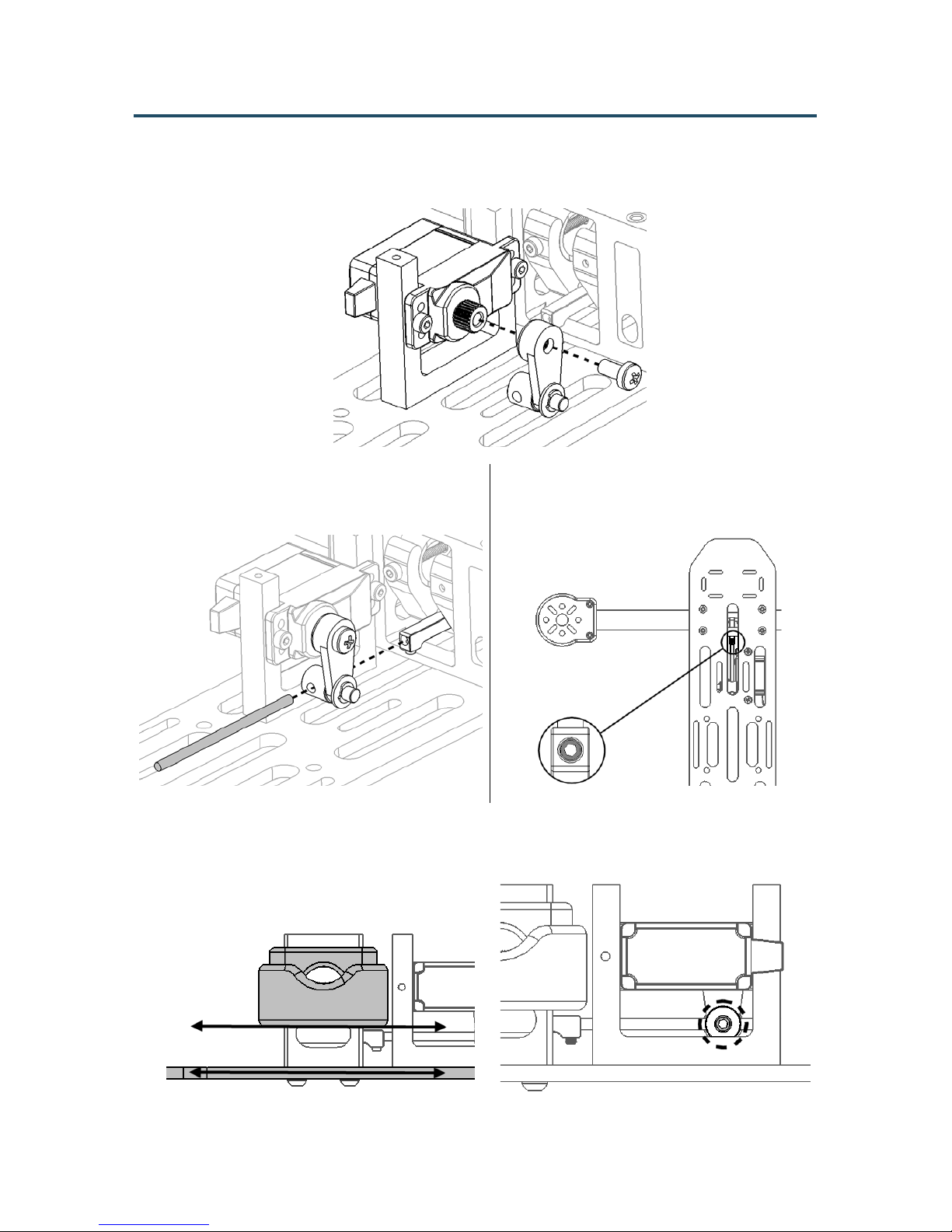
9. Using a suitable servo controller, center the servo spline. Push the servo horn onto the spline
and secure in place using the M3 screw supplied with your servo.
10. Slide the Short Push Rod through the Servo
Horn & Linkage Stopper Assembly and
into the rod end as shown.
12. Align the Motor Mount to the Base Plate and tighten the set screw on the linkage stopper.
11. Tighten the set screw on the Rod End.
Page 8
VECTORQUADS
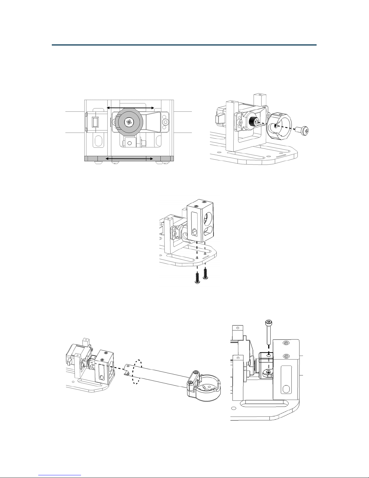
13. Using a suitable servo controller, center the tail servo spline. Align the flat surface on the
Servo Tube Hub to the Base Plate and push onto the spline. Secure in place using the M3
screw supplied with your servo.
14. Mount the Tail Tube Pivot Block onto the Base Plate using two Button Head Socket Cap
Screw M2.5x0.45x8.
15. Push the 12mm Tail Tube through the hole on the Tail Tube Pivot Block using a twisting
motion. Secure in place using the remaining Button Head Cap Screw M2x0.4x18.
Page 9
VECTORQUADS
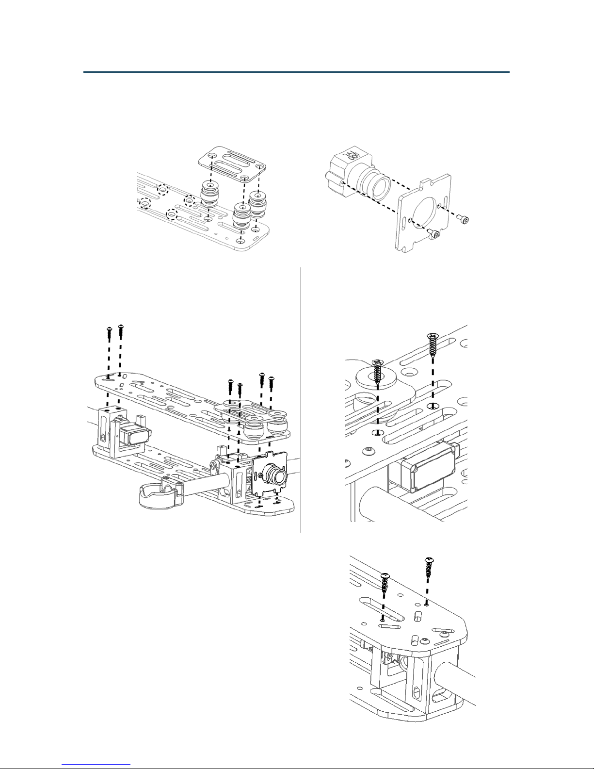
16. Install the Vibration Dampening Rubber Balls and HD Camera Plate onto the Top Plate
noting the location of the countersunk holes. Prepare the FPV Camera Plate at this time as
well.
17. Mount the top plate and FPV camera plate
onto the base plate assembly using the
remaining six Button Head Socket Cap
Screw M2.5x0.45x8.
18. Use two Flat Head Phillips Screw 9mm
Length to secure the servo mount frame
to the top plate. Do not over tighten
screws.
19. Use two Pan Head Phillips Screw 9mm Length to
secure the Tail Servo Mount Frame to the top plate.
Do not over tighten screws.
Page 10
VECTORQUADS
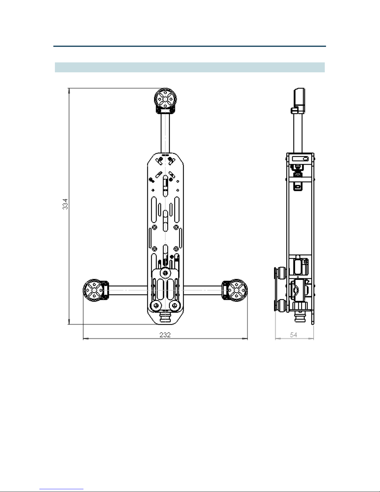
Mechanical Specifications
Empty Weight (excluding servo): 193g
Length: 334mm
Width: 232mm
Height: 54mm
Tilt Rotor Angle: +50º / -40º
Tail Rotor Angle: +45º / -45º
 Loading...