

Vectornav VN-200 Quick Start Manual
VN-200
Development Kit
Quick Start Guide

2
10-0003-R3
Copyright © 2019 VectorNav Technologies, LLC
Thank you for purchasing the VN-200 Development Kit from VectorNav
Technologies. This Quick Start Guide will assist you in getting the VN200 configured and operational. It will also introduce some common
operations performed with the sensor. For more detailed information
please refer to the VN-200 User Manual, a copy of which is provided
with the Development Kit and is also available online at
www.vectornav.com/support.
Please do not hesitate to give us a call at +1.512.772.3615 or email us at
support@vectornav.com if there are any questions we can answer or if
we can be of any assistance.

3
10-0003-R3
Copyright © 2019 VectorNav Technologies, LLC
VN-200 Introduction
The VN-200 is a miniature, surface-mount, high-performance GPS-Aided
Inertial Navigation System (GPS/INS). Incorporating the latest solid-state
MEMS sensor technology, the VN-200 combines a set of 3-axis
accelerometers, 3-axis gyros, 3-axis magnetometer, a barometric
pressure sensor, a 50-channel L1 GPS receiver, as well as a 32-bit
processor into a miniature surface-mount or standalone module. The
VN-200 couples measurements from the onboard GPS module with
measurements from the onboard inertial sensors to provide position,
velocity, and attitude estimates of higher accuracies and with better
dynamic performance than a standalone GPS module or Attitude
Heading Reference System (AHRS).

4
10-0003-R3
Copyright © 2019 VectorNav Technologies, LLC
VN-200 Installation
Mounting the VN-200
You may mount the VN-200 to the vehicle or platform in any
orientation. If the VN-200 axes do not align with the desired vehicle or
platform axes then a Reference Frame Rotation will be required to
remap the attitude, angular rates, acceleration, and other data to the
desired frame (see page 9).
When installing the VN-200 to a vehicle or other platform, ensure that:
• The VN-200 is rigidly mounted with respect to the GNSS
antenna
• The VN-200 is rigidly mounted to the aircraft, vehicle or other
platform.
o Vibration dampeners or flexible mounts can degrade
the VN-200 performance and are not recommended.
• All harnesses are properly secured and strain-relieved to avoid
stress entering the VN-200 from the cabling.
• Great care is taken when connecting the GNSS antenna, as the
connector can sustain limited side loads and connecting cycles
5
10-0003-R3
Copyright © 2019 VectorNav Technologies, LLC
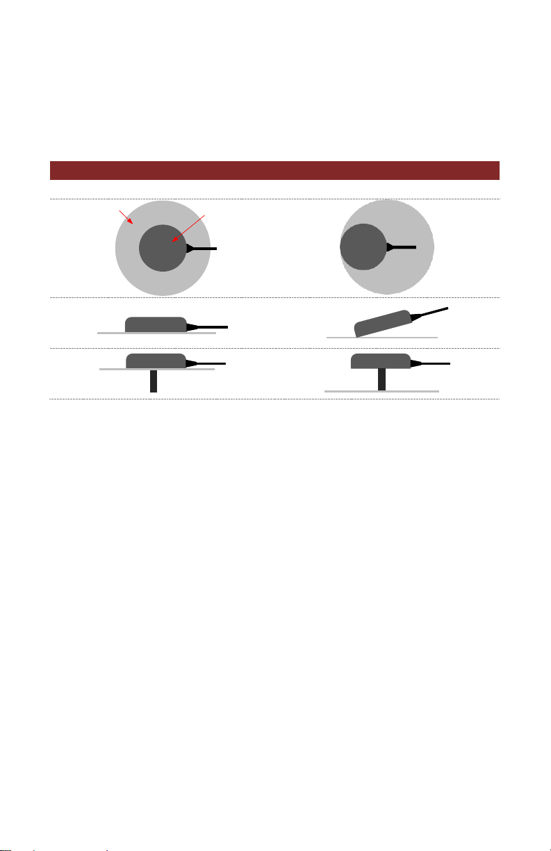
Ground Planes
To prevent multipath ensure that the GNSS Antennas are mounted
directly to a ground plane. Below are good and bad ground plane
installation examples.
GNSS Antenna Ground Plane Installation
Good
Bad
• Antennas shipped with the development kit have a
manufacturer recommended 100 mm diameter ground plane
included
• There is no requirement for ground planes to be electrically
grounded
• Ground planes can be any thin piece of metal (even foil)
Mounting the GPS Antenna
The VN-200 requires connection to an active GPS antenna, mounted
with a clear view of the sky.
In order for the GNSS Compass to function optimally both antennas
must:
• have clear view of the sky
• have a ground plane installed directly underneath the antenna
or be mounted on large metal surface
• be mounted as flat as possible, minimize pitch/roll to < 10°
Ground Plane
GPS Antenna

6
10-0003-R3
Copyright © 2019 VectorNav Technologies, LLC
VN-200 Start Up Sequence
Time: 0 sec
The VN-200 is operating as an AHRS.
Using the on-board magnetometer for
coarse heading estimation
Time: +30 sec
GPS Fix acquired. Local magnetic
declination applied. VN-200 still
operating as AHRS.
The VN-200 needs to exceed 5 m/s for
more than 1 second to start dynamic
alignment
During dynamic alignment accel and
GPS data are correlated to produce
yaw estimate. Typically take 60
seconds of sufficient motion to
complete alignment.
VN-200 Heading uncertainty is now
below 2 degrees. Sensor operating
within specification.
 Loading...