

Page 1
+.v
[
iiODsii@)
!~:t
.~
704LSJ.4
"
I.
I.
I.
74LS144
I
I
I.
MD,
IS
MD7
MD_
WAiT
iiffiT
",0
..
V
•
-=
•
24
26
14
IS
•
17-
16
D,
I
2
D7
•
iiiT
iEi£T
NMI
iiiQ
U23
ZIOI
MK3"4-6
PROCESSOR
\
-=
HAlT
iUiiK
iFiii
ii
iii
iii
iRED
iOiiQ
v
II
10
W-
.E
GNO
-=
II
23
2.
27
22
21
19
20
'iREQ
IAI5
BAI
IA13
..
u,,~
+llV
•
-5V
•
+SV
•
."11
-=
-=
ROn
p,
20
01
>------=~
.,.
74LS14
"
+.v
...
I.
~~---~~--_JL_-=:::::t1t::::::::::~L-~~
,r:-~
......
-...:.=<><lI3/-'''-< .....
-
--
--iii
- - - - -
.,
__
~L'
---
Page 2
D(SCRIPTlDN
,----+~
+:v
"~I$
l:--f
2 ~ 2
e
7.
I ~ I
,.
----!
:-
r OfAIOGND
1011,
------.
~
......
~
---....r-
~
:=:::
12.
vee
I
U20
~
3 2732.
~
•
(27XX)
:"-?'
0-
6
--:;;
7
,#
••
PRG./Ci
All
19
~2
'21
1374L520
::r-'
tT---'~~~U~'30"!'4-",!1~3.f>i
12 V 1
7.lSI.
~~12!.t-!-1
+:v
12.
iEffi
74LS74
10
PR 9
~D
ar----~l1
lllljl
>U27 12
-I
Q~
-=
CLR
13
+sv
I 2 13 1 2
~, ~ ~.~:q:
~
:r.-::
:g/
!~ ! s~
,~
.~ • 7~
D7:!!;
.07
~02
~13
U2'
12
U9
~-+~""fv------~-.+'v
~
vee
· 2
0-
2
~
,.~.
I ~ •
.AIiI ~ A9
~
PRGtl/CE
*"
r OE"IO
_...!..-_
ItOM2
1097
14t>.IJJ~JPHANTO
~15
74LS10
R4
4.7K
1t3
4.7k
D'1!c(
2
2~2:X
I
fIT"
GND
••
112
7"
~-----
~
2~
!~
,~
.~
07
All
121
I
Rlr
II(,
f!V
67
3
:
7
iii-.......~·ROM.
IAI4-~
'AI3-~
IAI:I
J--""
..
Ull
-+",0-(:>'-+-""":'-1
IAIO
1~?:~:J--..:.::.t.
__
....:~f""1~=£:3
cr·~~+---~~-+~~~~~4
2 12
Qi
Q.!
r--
tt
7~3
l2.e
...
~.~
11
74LS...
10'
• 9 U9 3 ~ 3
1
12 13
:
5
:~
~
.!...
~IO
J
..
I7--+....;.I-
L 74S0'
2 7 I
74504
I
U9
9600
~:~~
1200"...,.
60
300,.
:~..
.......
6
BAUDS1RATE
r-::::
~
.ESET-,I'~3po.:.2-t
5 220
11:26
•
2~364"
~
"21
___
......
..,2,,2"r.
~+SV
,24,
-----1+5V
UI
22
+,y
-:!,- _ I
-=-
~
Girt"
r
lit
:C
I
----
~=F;~~t~~7~=;~iSE~L~E~CT
r ,
~
L...!..c
eK
~A
UI
Q~
~
CUt
Q 6
~
13
:-.0
UI
ac
,-E-
eLR
••
_
IJr-
~
CK
a
UI
:~t-~5
2 eL"
g,
t
~
""
OA6
lA,
•
3 6
:2
.1.
Z1
L~·lmi~·~·f·~ES!!I~ST~O!.~p.;e:.~'~:+~':v_..1
.~~.~
2
,
IIID~
::;
..".,..t+
-
INP 3
OUT~~j>~2~
..
2
1A3
...
_____ 1.-.-.:;
_
SER
IIIA"-.g
74LS14
po
74LSO'
15
741.$42
14
'3
12
~
--;.:.
..
u2
a~
ROM
11--
L-E.,
U4
AOIII
74LSJ2
+1:.
~
0"
,"1
'=!
D~
20
elK
TiC
22"'tm
II
_
cs
c/O
~
WRiffiGNDR:E::'rYr
____
________________________________________
0
.
2
3
TXD~~~"
:2
U6
RXD 3 11
AM95S
I 9 I w
m
s _
QSR
iTS
_
CTS
TX
ROV~
TUT
SYND£T~
.3=
I..
1"
=-
+
____
.-.-
3
•
10
1"'1"'1
,
15
MAl>
•
MAT
2
l
•
,
•
"---..!. 3
~
•
2
!
s
.
,.07
•••
• '--...!.!.
'0
11
12
.2.
••
'J:;:;-
MollS
.3
..
'--.l!.
•
+,v
•
••
si@..;
'''LSD''
+'V_-1
__
--,
I
L1..D
"3
4.7K
el
J
til--=-
7.lS7.
'4lSI.
7
'-
PRi'iET
7 5
I
2
.>-'",,12""1I0"°---1~_·--t3
"'
___________
+,v
+
X··
-,~:vtiUr:~
••
16 13
r<?15
24
10 UIS •
~.
~~
~3
13
U15
17
J 1 (s)
1419
r.::-
____________________________
+,v.---,
ZI ItS
I.
T1
r9
(.)
7
'23
13
A22
~1
(01-2')
(PINs)
EXT
_NIIONS
,UCTIONS
"
IK
APPliCATION
Asn
lOl£JtANCU
-
ANClU-
xu.-
1(X-
MOl ~ 07
••
IIIAI--.!.
PAR~
US£D
lfit
,;0,
II
rf{12
6'1-'--+-<.,":Y;~-J""01\,'''.7r.''''+'v
'n.L·'~'-I"""'VV"V-'
...
~O
-=
I.
•
"
•
••
2
••
• 3 7
17 3
..
•
.2
•••
7
..
LS2
....
.3
7
•
39
••
•
'2
•
,
15
2
••
•
••
3
3
•••
r-k-
as
021
> 3
Q
~
eLR
-b
I
+!y
,~r..~_'-~~~~~------~{)~--'
.~
I
2'¥. 2
l~
.~
s~
.~
,--2.
3
.
,
.
A'
AI
'255
r""
rIAl
U
r
r""
u
r
r"
lAIO
r
rIA"
lA12
r
r"
rIA,
riAl'
.7
".
..
2.7K
rt<
..
1~1~1
6
58
a
UII
rt:~ Q ~
.-:-:-:-:
-=+5\1
74unl
R"
4.11(,
~
+ r
t:;;l-S
14
e15
X
100
[2
•
U
..
'
•
A7
Al3
...
14LS'l'2
S •
6
U1I:>o','-1
+sv
iiffii
cs
..:3,'
"E'ET
S
RD
~3~==WRW'
l
__
~~~~F====18~~J
GHO
-:!,-7
OAT(
OWN
ON
INeHlS
ENG
....
SCAlE
DATE
DATE
SHEET
I
or
TllU
SCHEMATIC
CODE
1.0.
I
OWG
A
<1!1
tI
:::liI'
(!j]2
<JIl3
~
.
"G!J'
,-ru
•
~
~A7
Aa
::::E
~.
'0
~
.:E
"
::::m
'2
:::E
'3
<!!J
14
A15
-::::B:
1091
4~5
Jr',~·t>I""""
~
NO
3501000'
r"'r
99
;oc
lCI
O'
00
Sill
D
Page 3
+:v
....
...,,~
yee
.,
~
.
.,
I~
'~D'
,:--g
I
l'4
•
~3
,'-f
•
':-+.
S
''fi
6
,~
D7
U23
llOI
.K3114-6
PROCESSOR
--.!.
+
~iiii
-2!.
iEffi
'7
-l--!!MiI
~iiiQ
~
BuiiiQ
I
GND
AIS
iiii.l1":::·---'1·,I<·"'p...:.:'-....:.:.toj:~--<41
RFiH
iii
WiI'·~1'-
is
~~I~·------·~~:.R£.
IoiiQ
I
•
?V
•
3,¥./ 3
4~
4
:~
:
7
:g..-
7
.
*'
I
.~
.
11O~
10
11
+-'
11
12~
"
13~
13
I
~
I.
2../
MAtS
1:~LSO:a
3/(.
V
2'
21
____
21
20
dF~>,>-,I,-------....,
I
~"'S;4LS109+S~
l.! J
PR
Q 6
,-4
...
U26
p---c
I
~ K Q~
I ±
(LR
- 1
+SV
Cl0
.,
330
ell
~L.J'HOI~~
~...--,'
Y I D
100
12
PF I MHZ
J
~2
C
13
K Q 9
+SV 15 13
.1
>.,
3,0
JI
_
:~
MHZ/
.,
...--
-
~
74LSIO •
~"'
+sy
,
~
-
3
U19 !
+~
o"!"
U30
11
,.
~
.,1
4.71\
..----!
+Sy
•
O..!..
0
U30
3
>
• ,'_
I~
• M
• N 4
sN.
.~
'~7
'~I
IIlA9 ~ "9
R!!
WR.....:.:.c
.~097;
14
1~3
U)
:I:
~ J ~RFSH
14
I
1~
~1~2~~ii
10
I 9
6
W--
~s
~2
~>-'~0-""sh6
PI
QI"'O"+--t,,-,,12'iD
U26
..........:....>
CUt CUt
I 3
~'.:>c":"""'-O-j>
74504
I
+IVm:>-J
"
IE>-
m>-
ffi>-+
GND
!E:"
[E>--<
1§9>-
16y
-
::TI::
I"~'_.,
~.,
yee •• "
I
...
i!!/
~
~
U2S
j I
flV
.".-.
.flV
--ioc
CE
6
WE
GND
D3
11
f!!-/
.D3 7 l.,.,.
~ ~
SOSI
SHlTA
9
~PHLD~
'iT
iD
10RO
+SY
10
PR~Cl
II
U46
Q~
+SY 13
TOLS74
(.)
__
r
~
~
'2
9
SY
+r
I7_
PI! 5 A
U.6
CLR
+sv
.--
U17
12
~I
U17)
f--
1
S
Y
'
,+3..
_
Q~+--Y-'l
Q
~
I
I
'1R"
T
(9 + 7IDS
~o
21f
___
-=-
e
.... _ .... _-+_
'905
c
i9f
L---+---"-,
,r;;;,o
7.1.'
I~
I • M
, 4 N 4
••
6~
'~I
IIlA9 ~ "9
RA~
Wi
__
r--2l
3
I
+2
0
F---f-t"-e-'-"t'"-------+Sy
F-t---<~---1~-------------<l+SY
~f--1-----
.F~-"t'"J..-e-s-----
f-t--'r------+
H:=====:"'L-~:""-I'CLK
.574
'
.,
+Sy
Til
~.,
yee
I
~
U24 j I
.".-,
N s ,fE/ 6
6
7
~
CE
~
WE
GND
+sy
10
.:.:12'-jD
PR
Q!-'9,-..".6j4
>UIO
13
eL'-i"
+Sy
'097
.........
rIO~~-=~.,..:.._-<l.
I'
~
~PCLK
~.~.
-,
74104
13f.:':t...
1'2
V
PUK
"",VV'\r4>--+-i
12
1-+
e6
1.
,
f
...
_._'_..J
T
.~
...
~-
l'f
~
S •
.~
D3
6~
.!!/
.D'
7
'~I
1Il..,9 ~ A9
~
~
Roh
1097
""b~'--<!'.
~
-
"
(30
33
PF
11:25
t-t--'V'VIr-<P"-'V\""'.
R27
~
~f>';':---"""Vv\"'.
(20,21,22,23.24,
.1
e12.
1
·
~
1.2
74S04
'S,,..27,.....
13.16.
17,
11,19
-
Sy
~g
-12Y
12Y
+!y
~.,
~
:"4 • ('7XX)
'::+.
r
220
I"
yee
•
I
U.O
~
213
..
s
6
'
PRGIIl/CE
0(1010G"D
All
19~2
11
ill
""14-
r:o
IAIJ-r:o
BAll
-f~30-<Y:-f-~"
1126
22
+.y
2~13644
"21
22
-::!=-
~
.."
~
~
~I'
•
~
•
3~
3.:"4.
.~
• s ~ s
.~
S16~
6~16'N:'
~7
~
1107
IIlA9,,#
? r
7
..
LS14
13
g::
'.LS393
13
1
r---:~"
L.::o
•
DI· ~ 11
UI
til
U:
Q.
'---
I .
r----
L...!c
Ck Q 3
01"
Ul
ac
r-L
CUI
Q 6 I
'---
I
~
~~:O:-'
UI
QC~
,-E-eUlQ'.!...
-
~r-3
:.:~
~
eUOD..!...-
1'--
,.uo
..
12
IAT
•••
us
,
+:v
I ••
~.,
yee
!
~
; u21
~
3
27XX
6
.~
•
"9
rl
PRc.1ff
DE
AIO
GND
,,.
112
-=
iiEffi
10
PR
Q~~l
>U27
ii~
CUt
13
+sv I
7'LSIO
10
9 8
9 u
12 13
7 SELECT
74$04
'2
All
9600
"100
2400
1200
_~_
ROIllI
14LS14
12
l
-=
C 9
5
r1lo
1
11
J
-t-.J
~O
t-~s
U9
6
74S04
,,'
21
'.LSD'
12
13
~-+~'VIty---~
U9
u2I
lr"'l
13
12
74LSID
"4
R34.71(
.097
~--
14~131
.......
L.:JIS
4.7K
C,.,.IPM(i;i
~F-'
__
Rll
1M,
+SY
,,!L
+Sy
flO
.,
t'¥.
D'
,~,
.N
,
-'-."'0
0
'2
3
3
..
07
eLK
13
_____
U6
..
""
g
__
-
3
I.~
I
IAUi1RATE
r::::::::
......
......
~~
150
::.
110
,.
'---
••
S.T~I~~3~~1-i----~--
INP 3
OUT-L~P.""'-<I>-
...
IAl
""
•
"l-:-
:~ ! Dsi~
MD7'-!
'--
__
7"LSI"
r:::...
..
l7
74LSO"
IS
U.
74U42
14
13
0
"
10
_1':
TXD
...
_,
OTlt
ru
'21
~_
_
11
'
1
Page 4

,,----
. .
{Z@[ID
~~~[~~~
[ID®&OO(ID
@®~LVruJu~OO
.
~
..."
. . . t ' $ ( .
Page 5

ZCB
SmGLE
Revision 1
USER
Revision B
JlB'le
OOARD.
I S
MANUAL
11,
mtPt1I'ER
1980
Ccpyright
1980
Vector
7200-0203-03-02
Graphic
Inc.
Page 6
Vector
Section
ZCB
Single
Board CCJtplter
Table
Specifications
I.
Perspective
1.1
1.2
1.
1.4
1.5
II.
User's
2.1
2.2
of
Contents
The
ZCB
The
ZCB
3
c::l'{J
sectiOll
~
I/O
sectial
1.5
.•
1
1.5.2
1.5.3
1.5.4
1.5.5
1.5.6
Guide
Introduction
2.1.1
Cl?U
Sec-tial
2.2.1
2.2.2
2.2.3
as
a system
as
part
••••••••••••••••••••••••••••••
of
a system
••••••••••••••••••••••••••••••••
••...••••.••••.................•.............•..
section
••••••••••••• ~ •• o
Serial
Serial
Serial
RS-232C
RS-232C
Paral.lel l?C)'rts
.•...•..•••••.••......••.•................
•••••••••••••••••••••••••••••••
Ports
Generally
••••••••••••••••••••••
Asynchronous Communications
Synchronous Communications
Theory
on the
•••••••••••••••••••••••••••••••••••••••
ZCB
••••••••••••••••••••.••••••••••
•••••••••••••••••••••••••••••••••••••••
•••••••••••••••••••••••••••••••••••••••••••••••
Standard
Running
~
Auto
Jumpering
•.••••••.••••••...••••
the
system
erlable/
WAIT
disable
state
erlab1e/disab1e
and
at 2 or 4 MHz
•. '
what
.......
•••••••••••••••••••
••••••••••••••••••••
it
does
•••••••••••••••••
0
•••••••••••••••••••••••••
••••••••••••••••••••
It
•••••••••••
••••••••••••••••••••••
~
•••••••••
e
••••••••
e
•••
III
.....
l-l
1-1
1-1
1-2
1-2
1-2
1-3
1-3
1-4
e
•••
1-5
1-6
2-1
2-1
2-1
2-1
•
2-
2
2-2
Rev.
2.
2.4
1-8
3
~
2.3.1
2.3.2
2.3.3
2.3.4
2.3.5
2.3.6
2.3.7
I/O
2.4.1
2.4.2
2.4.3
2.4.4
6/1l/80
SectiCll"l
2708
AuXiliary
2716
2732
••••••••••••••••••••
EPRCMAddressing
Memory
EPROM
EPROM
Addressing
Addressing
Enable on-board
Phantan enab1e/disab1e
Jumper
Sectial
I/O
areas
K,
••••••••••••••••••••••••••••••••••••••••••••••••
Pc>rt
Mdressing
Address Mirroring
Asynchronous
HOw
to
connect
Serial
most
'
••••••••••••••••••••••
•••••••••••••••••••••••••••••••
Disab1e
••••••••••••••••••••••••••••
•••••••••••••••••••••••••••••••
•••••••••••••••••••••••••••••••
EPROM
on
boot
•••••••••••••••••••••••
••••••••••••••••••••••••••••••
Land M
•••••••••••••••••••••••••••••
••.•••••••••••••••••••.••••••••••
disab1e/enab1e
Baud
Rate
serial
••••••••••••••••••••
Se1ection
terminals
and
•••••••••••••
printers
•••
2-2
2-3
2-4
2-5
2-6
2-6
2-7
2-7
2-7
2-7
2-9
2-11
2-11
Page 7
Vector
ZCB
Single
Board Ccltplter
Section
2.
III.
'lheory
3.1
3.2
N.
Schematics
2.4.5
2.-4.6
2.4.7
2.4.S
2.4.9
9 Spare
of
System
Serial
How
to
connect.
JOOSt
COnnecting-additional
USing
the
COnnecting
Parallel
Sprint
Connecting Vector
Clip-
and
Patch
areas
Operation·
operation
Ports
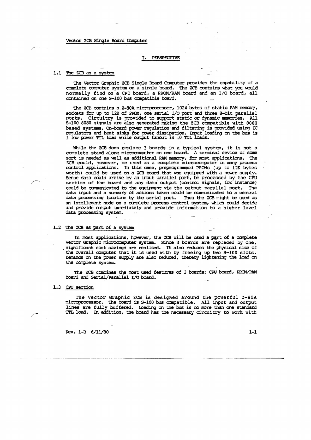
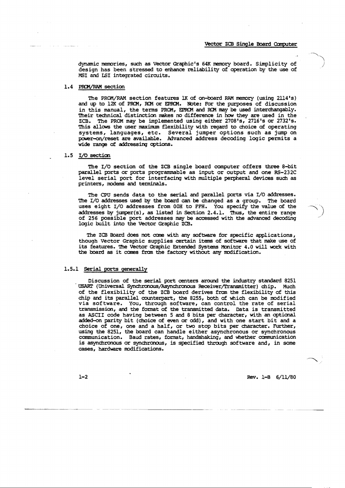
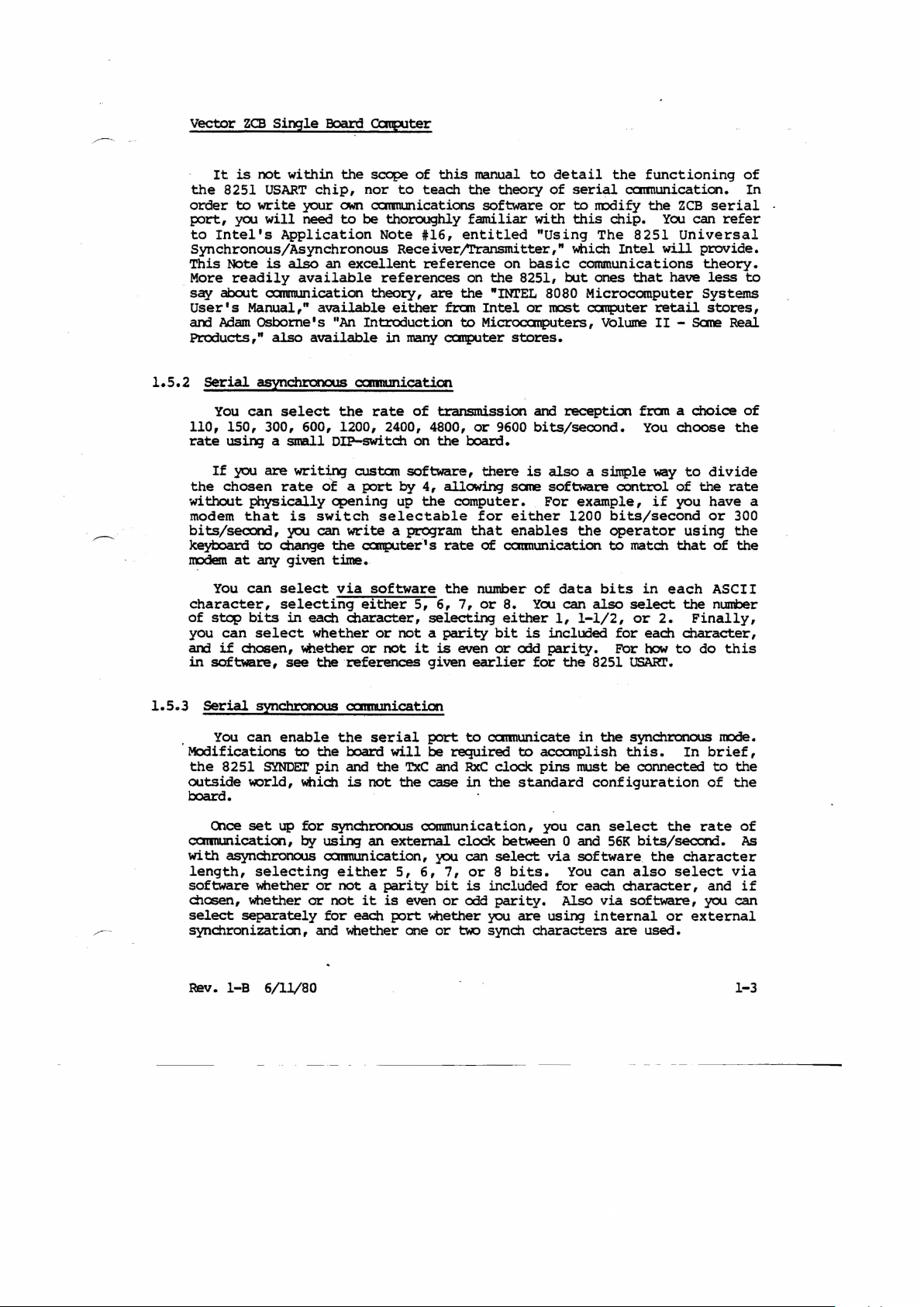
Block Diagram
•••••••••••••••••••••••••••••••••••••••••••••••
low speed
RS-232C
Ports
3
to
ZCB
MP
to
accustic
handshaking
cooplers
lines
••••••••••••••••••••••••••••
••••••••••••••••••••••••••
ZCB
•••••••••••••••••••••••••
•••••••••••••••••••••••••••••••••
•••••••••••••••••••••••••••••
~
•••••
•••••
2-15
2-l5
2-lS
2-l9
2-19
2-20
3-l
3-2
Rev.
l-B
6/ll/S0
Page 8
vector
ZCB
canpatibility:
Po\oter
Requirements
Single
Board
COtplter
SPOCIFlCATICNS-System
Most
5-100
systems.
+8VOC @ 970
+16
VDC @ 120
-16
VDC
@
rna.
SO
(typ.)
mao
rna.
Availabili
EPRQ1s
board
Mem:n:y
Standard
Systems
1?oWer-on~set
ty:
included
Speed
r.ocatiat
~i
tor
with
of
EPIOt
Junp
Options
Processor
Nunber
N\:mt)er
of
of
Data
Mdress
Bits
Bits
Shi~
65536
3
nooe
RAM:
EPRCM:
RAM:
EPROM:
EOOOH-E7FEH
Auto
EOOOS.
assenbled,
SPECIFlCATIctS-EPRCM/RAM
bytes
addressable,
EPRCM
sockets
300ns.
User
2114
270S,
bOot on power
Shipped
selected
static
2716,
on
board,
on/reset,
enabled.
SPOCIFlCATICNS-CPU
Z-SOA
S
16
tested,
(450.
2732
burned
1024
up
ns.
bytes
to
12K
typical)
jl.mpS
in ~ no
RAM
kits.
on
addressable
to
rneIID1:Y
board,
location
Instructions
Clock
speed
Interrupts
I/O
devices
Dynamic
Rev.
I-B
RAM
6/11/80
15S,
including
2
or
4
MHz,
Z-SO
Mode
I/O
256
Supports
on
bus
line
generated
all
78 S080
0
j~r
(SOSO
selectable,
rro::1e),
addresses
dynamic mem::>ty
66
~
fast
on
board.
instructions
MODE
1,
by
sending
resetlJ;:ower
enabled
mDE
Z-80
on
clear
for
2
4 MHz.
RFSH
signal
Page 9
Static
RAM
Fully
canpatible
vector
ZCB
Single
Board
catpJter
•
MWRITE
wai t state
for
memories
than
300
Bus
!Dad
Bufferin;
Phantan:
Mirrorin;
.
capacity
Serial
Port
generation
ns.
port
addresses
slower
Jumper
Standard:
3
cycle,
instruction,
Standard:
instruction.
1
Fan
OUtput
~
Power-on-clear
Standard:
Standard:
1
as
1,
Any
addresses
Control,
option
option
options:
stamard
out:
serial
input
using
increnent
generate
generate
generate
T1'L
15
standard
buffer
Boards,
enabled
enabled,
SPECIFlCATICt&-I/O .
RS-232
or
output.
8251
are:
05H
to
generate
enabled.
one
generate
one
load
disable
which
(PCX:).
can be
and
controller
of
four
Data,
(echoed
MWRITE
one
wait
state
wait
wait
state
all
inputs
generate
Jumper
disabled.
chip.
OOH
(echoed
07H.)
state
states.
selectable:
wait
no
.on
(60 low power
canpatible
3
8-bitparallel
fran
04H
on
on
after
after
with
phantan
to
FFH.
on
board
on
each
each
each
shottky)
Vector
in
ports
Preset
06H)
1
bus
Ml
Ml
Graphic
response
on/off.
programnablt:.
to
,,.--.;)
Signal
RS-232
Asynchronous
levels
handshakin;
Rates
Data
Step
parity
bits
bits
EIA RS-232C
Typical
DSR,
Uo-9600
5 -
handshakin;
etc.
baw
8,
programnable
1, 1 1/2,
Even,
ood,
is
(switch
or
2,
or
oone, programmable
selectable)
programnable
provided,
ie.
RI'S, ers, OrR,
Rev.
l-B
6/11/80
Page 10
,.~-~
vector
Synchronous
ZCB
Single
Board
COtplter
Clock
Parity
Data
Sync
Parallel
Port
latching
Signal
N\..mi:)er
Rates
Synch
bits
character
Ports
Addresses
level
of
detect
lines
OC-56K.
can
be
wired
for
8251
SYNDET
N:lt
now
for
synchrcnous
Even,
odd,
5 -
8,
Single
2-8
bit,
an 8255
Any
increment
addresses
and
the
output
Tl'L
(i.nt:ut = 1 low power
load)
•
8
lines
+5
VOC
line
connected
or
none,
programmable
or
double
2-4
bit
parallel
of
are:
Cootrol
latched,
per
channel,
and
GND
internal
is
not
to
the
operatioo.
progranmable
synch
can
be
I/O
controller
four
:Ebrt
A, 08H;
Status
input
progranmable
are
also
or
external
connected.
external
character
programned as
chip.
fran
OOH
to
Port
Register
not
Tl'L
at
latched.
load;
provided.
\4\Orld
can
FFH.
B,
000.
output
for
synch.
as
be
progtaliiled.
3-8
Preset
098;
:Ebrt
input
required
bit.
C,
drives
or
Uses
OAH
1 'l"l'L
output.
Rev.
rata
cable
1-8
transfer
6/11/80
OVer
lOOK
Cptional.
ribbon
allowin3
ordered
bytes/second.
Has
34-pin
cable.
user
to
separately.
N:l
connector
configure
female
connector
is
at
as
required.
the
and
other
r-tlst
34-line
end,
be
Page 11
vector
1.1
'!be
The
canplete
normally
rontained
'!be
sockets
ports.
5-100
based
regulators
1 low power 'r!'L
ZCB
ZCB
as
Vector
ZCB
for
8080
systems.
Single
a
Board
system
Graphic
canputer
find
on
on a CPU
one
5-100
system
contains a Z-aOA
up
to
Circuitry
signals
and
12K
are
~
heat
load
is
sinks
while -ootput
c.atplter
I.
PERSP&:TIVE
ZCB
Single
Board
on a single
board, a PROM/RAM
bus
canpatible
miCtopLocessor,
of
PRQ1,
one
provided
also
generated
power
serial
to
regulation
_for power
fanoiit
canputer
toard.
board.
'!be
1024
I/O
support
static
making
and
dissipation.
is
10 'tTL
provides
ZCB
board
-
bytes
port
or
the
ZCB
filtering
Input
loads.
rontains
and
of
and
three
dynamic
compatible
is
loading
the
capability
what
an
I/O
static
8-bit
merrcries.
provided
.
board,
RAM
on
you
rnerII)ty,
parallel
with
using
the
bus
of
a
~uld
all
All
8080
IC
is
complete
sort
ZCB
control
worth)
Sense
section
could
data
data
an
and
data
1.2
'!be
Vector
.
significant
the
Demands
the
board
1.3
CPU
mictq?rocessor.
lines
'r!'L
While
the
stand
is
needed
could,
applications.
could
data
of
be
ccmmunicated
input
processing
intellegent
provide
proceSSill3
ZCB
as
In
most
Graphic
overall
on
canplete
The
ZCB
and
SerialjParallel
section
The
Vector
are
load.
ZCB
does
alone
as
~ll
however,
be
the
used
arrive
board
a
SlIt'I'IBry
ccW.d
and
location
node
ootput
bmmediately and
system.
part
of a system
applications,
microcuuputer
cast
savings
ccmputer
the
};:OWer
system.
carbines
Graphic
'!be
fully
In
buffered.
addition,
replace 3 boards
microcallputer
as
additional
be
used
In
on a ZCS
by
and
to
on
a
as a complete
this
case,
an
input
any
the
equipnent
of
actions
by
the
~lete
board.
data
serial
h9Wever,
system.
are
it
IOOSt
I/O
the
realized.
is
are
used
board.
ZCB
is
5-100
tDading
board
used
also
is
that
supply
the
board
in a typical
on
one
board.
RAM
mem:n:y,
preprogrammed
that
was
parallel
output
via
taken
the
rould
PJrt.
process
control
provide
the
ZCB
will
Since 3 boards
It
_also
with
by
reduced,
features
designed
bus
ccmpatible.
on
the
has
the
necessaty
A
for
rrost
microcollplter
PROMs
Eqripped
p:Jrt, be
(ca1trol
outp~t
be
cx:mnunicated
Thus
the
system,
information
be
used a
reduces
freeing
thereby
of
3 boards.:
around
bus
is
no
circuitry
system,
tenninal
applications.
(up
with
processed
signals,
parallel
ZCB
might
which
to a higher
~rt
are
replaced
the
physical
up
two
lightening
CPU
the
powerful
All
input
nore
than
it
is
device
in
a power
many
to
by
for
of
process
12K
supply.
the
instance)
port.
to
a
central
be
used
rould
decide
of a canplete
by
size
5-100
board,
slots.
the
load
PRaVRAM
Z-80A
and
output
one
standard
to
work
not
sane
The
bytes
CPU
The
level
one,
with
a
as
of
on
Rev. I-a
6/11/80
1-1
Page 12
dynamic
des
i9n
MSI
1.4
P10VIWI
The
and
in
this
Their
ZCB.
This
systems,
p::lWer-on/reset
wide
1.5
I/O
The
parallel
level
printers,
The
The
uses e igh t I/O
addresses
of
256
logic
merories,
has
and LSI
section
PROM/RAM
up
to
manual,
technical
The
allows
ran9E!
sectioo
I/O
ports
serial
CPU
I/O
addresses
possible
built
such
been s·tressed
integrated
section
12K
of
PRCM,
the
distinction
PROM
may
the
user
languages,
are
available.
of
addressing
section
or
ports
port
nodems
sends
and
data
used
addresses
by
jumper(s),
port
into
the
as
Vector
to
circuits.
features
RCM
or
terms
be
implemented
maximum
etc.
cptions.
of
the
programmable
for
interfacing
terminals.
to
by
the
as
listed
addresses
Vector
Graphic's
enhance
EPRQt.
PROM,
makes
flexibility
Several
h3vanced
ZCB
single
the
serial
board
from
OOH
may
Graphic
reliability
lK
of
Note: For
El'R<l" and
no
difference
using
address
board
as
with
and
can
be
to
FFH.
in
Section
be
accessed
ZCB.
Vector
64K
rnenory
on-board
RCM
either
with
regard
jumper
input
multiple
parallel
changed
2.4.1.
ZCB
board.
of
operation
RAM
the
purposes
may
be
in
how
2708's,
to
options
decoding
computer
or
output
perpheral
ports
as a group.
You
specify
Thus,
with
Single
meI'OC)ry
used
interchangably.
they
are
2716's
choice
such
logic
offers
and
devices
via
the
the
the
advanced
Board
Catplter
Simplicity
by
the
use
(using
of
of
2114's)
discussion
used
in
or
2732's.
operating
as
jump
permits
three
one
RS-232C
such
I/O
addresses.
The
value
of
entire
decoding
of
of
the
on
8-bit
as
board
the
range
a
~.'\
I
/
-~.\
)
The
though
its
the
1.5.1
.
tJSARI'
Serial
of
chip
via
transmission,
as
added-on
choice
using
communication.
is
asynchroncus
cases,
1-2
ZCB
Board does
Vector
features.
board
as
ports
The
it
generally
Discussion
(Universal
the
flexibility
and
its
parallel
software.
ASCII
and
code·
parity. bi t (choice
of
one,
the
8251,
hardware
not
cane
with
arry
Graphic
Vector
canes
of
the
supplies
Graphic
fran
serial
the
certain
ExteOOed
factory
port
centers
Synchronous/Asynchrooous
of
the
ZCB
board
counterpart,
You,
the
fotmat
having
one
and a half,
the
board
Baud
or
synchronous,
through
of
between
of
can
rates,
the
software,
the
5
and
even
or
handle
format,
is
specified
transmitted
or
nodifications.
software
items
Systems
without
around
for
of
software
~nitor
arry
tredification.
the
Receiver/l'ransmitter)
derives
8255,
8
bits
odd),
two
stop
either
handshaking,
fran
both
control
data.
per
and
of
character,
wi
can
bits
asynchronous
and whether
tbroogh
specific
industry
the
flexibility
which
the
Data
th
one
per
character.
software
applications,
that
4.0
will
standard
chip.
can
be
rate
is
transmitted
with
start
or
synchronous
cannunication
and,
Rev.
I-B
make
use
work
of
modified
of
serial
an
optional
bi t and
~r,
in
6/11/80
of
with
8251
Much
this
a
some
Page 13
Vector
the
order
port,
to
ZCB
It
is
8251
to
yoo
Intel's
Single
not
within
USART
write
your
will
need
Application
Board
chip,
own
the
to
nor
be
Synchronous/Asynchronous
This
Note
is
also
an
More
readily
sc::/
about
User's
am
Manual,"
Mam
Products,"
available
a:mnunication
Osborne's
also
excellent
available
"An
available
Introduction
catpJter
scope
of
this
to
teach
communications
thoroughly
Note
#16,
manual
the
software
familiar
entitled
ReceiverjTransmitter,"
reference
references
theory,
either
in
many
are
the
fran
to
canputer
on
the
"INrEL
Intel
Microcanputers,
to
theory
on
basic
8251,
or
stores.
detail
of
serial
or
to
with
mOdify
this
"Using
which
communications
but
8080
ones
Microcomputer
most
canputer
the
functioning
ccmnunication.
the
chip.
The
8251
Intel
You
will
that
retail
volume
II
ZCB
serial
can
refer
Universal
provide.
theory.
have
less
Systems
stores,
- Sane Real
of
In
to
1.5.2
serial
You
110, 150,
rate
If
the
without
modem
bits/second,
keyboard
IlDdem
You
character,
of
step
you
and
in
software,
1.5.3
serial
You
Modifications
the
outside
board.
Olce
carmunicaticn,
with
length,
software
chasen,
select
synchronization,
asynchronous
can
select
300,
usin;J a
you
chosen
small
are
rate
physically
that
is
you can
to
change
at
ar'¥
given
can
select
selecting
bits
can
if
in
select
chosen,
see
synchrooous
can
enable
8251
SYNDEr
~rld,
set
up
asynchronous
selecting
whether
whether
separately
cc:mm.micatial
the
rate
600,
1200,
DIP-swi
writ~
of
custan
a
port
opening
switch
write
the
canputerl s
time.
via
software
either
each
character,
whether
whether
the
or
or
references
<XJmI.lnication
the
to
pin
which
for
by
the
usinq
serial
board
and
the
is
not
sync:hrornJS
an
camumication,
either
or
not
not
for
a
it
each
or
and whether one
of
transmission
2400,
4800,
tch
on
the
software,
by
4,
up
the
selectable
a program
5,
6,
selecting
not a parity
not
it
is
given
port
will
be
TxC
and
the
case
communication,
external
you can
5,
6,
parity
is
even
port
bit
whether you
or
or
bocm:1.
there
allowing
computer.
for
that
rate
of
the
number
7,
or
even
earlier
to
carmunicate
required
RxC
in
the
clock
7,
or 8 bits.
is
odd
~
included
synch
or
and
reception
9600
bi
ts/second • You
is
also a simple
sate
software
For
either
1200
enables
catmunication
of
8.
either
bit
or
clock
data
You
can
1,
is
included
odd
parity.
for
the
to
acccmplish
pins
standard
you
between 0 and
select
via
You
for
parity.
are
Also
using
characters
fran a choice
control
example,
bits/second
the
operator
to
match
bits
also
1-1/2,
in
select
or
for
For
8251 USARl'.
in
the
synchronous ItDde.
this.
must be
connected
configuration
can
select
56K
bits/seconj.
software
can
each
also
character,
via
software,
internal
are
way
if
each
2.
each
how
the
the
or
used.
choose
to
divide
of
the
you
have
or
using
that
of
ASCII
the
nuni::ler
Finally,
character,
to
do
this
In
brief,
to
of
rate
character
select
and
yoo can
external
of
the
rate
a
300
the
the
the
the
of
As
via
if
Rev.
1-8
6/11/80
1-3
Page 14
1.5.4
RS-232C
This
theory
manual
description,
by
Electonic
Street,
Da
tapro
N.W.,
or
articles
infocnatioo,
cannot
obtain
Industries
washin;ton,
Auerbach
describing
however,
a
will
cc:py
reports
the
describe
of
the
Association,
D.C. 20006.
protocol
be
of
the
RS-232C
RS-232C
EIA
Engineering
Alternately,
on
cormnunications,
and
irrmediate
its
relevance
Vector
protocol
ZCB
S'I'ANIl\RD
Single
in
detail.
document,
Department,
if
you
they
~lications.
in
contain
this
Board
For
published
have
access
The
following
manual:
Ccl1plter
a
full
2001 Eye
to
thorough
An RS-232C
Positive
industry
RS-232C
to
and
fran
(about 0 Wc)
An RS-232C
data
line
cot'resp)nd
also
associated
by
the
and
are
ccmnunication
receive
handshakin;
equipment
and a few
specifies
definitions
signals.
applications
In
fact,
the
very
above.
handshaking
protocol.
requires
.
expects
It
to
is
directional,
travels
on
protocol
device
short,
Tetminal
given
which
of
and
line
kind
signal
is
ON
wide cc:nventions
line
drivers
'rl'L
and
cable
carries
with
can
or
SPACING,
signals.
RS-232C
consists
a
the
characters
typically
serial
foonating
device
data
lines,
to
others
a
set
as
lines
inform
sane
that
of
of
that
each
are
rarely
the
Altogether
use oo1y a few
real
world,
few
devices
Many
require
lines
In
short,
"full
RS-232C." You IIIlSt
receive
important
that
each
line,
specifies
the
type
at
the
Equipnent,
can
be
of
device
vety
even
differently
it
on
each
to
is,
relative
that
called
other
or
"m'E"
determined
•
either
be
Negative
that
date
invert
Hence,
NB:;M'IVE
of
25
sequence
you want
and
parity
such as
there
are
are
used
other
rarely
used
primary
there
of
few
are
then.
devices
require
one
or
is
oonfusing
line.
understand
the
protocol
to
at
one
"Data
end
there
for
once
POSITIVE
back
is
to
these
(+12
OFF
the
signals
Wc)
or
RS-232C POSITIVE
corresponds
lines.
of
to
information
an
8251.
ground
by
ccmmunication,
of
their
used).
"secondary"
lines,
25
require
all
of
even
than
none.
defined
at
this
specify
that
RS-232C
to
An
RS-232C
PCSITIVE and
transmit
attached
In
lines,
status
The
full
lines
but
carry
"full
the
handshaking
Further,
by
tine
exactly
most
of
specifies
the
ends
of
the
end
of
an
RS-232C
Conununications
must
short.
you
be a device
The
direction
decide
which end
or
of
wilen
NmATIVE
key
telegraphy.)
they
are
MARKn«;. (These
days
corresponds
'l'1'L
high
(about 5 Wc).
transmit
NEGM'IVE
or
receive.
to
addition
(lines
the
to
the
1
and
7),
tetminal,
(lines
lines
4,
RS-232C
which
an
independent
defined,
RS-232C"
5,
6,
protocol
have
protocol.
lines
many
RS-232C,
to
say
that a given
what
signals
the
RS-232C
which
direction
cable.
cable
Equipment",
of
of
devices
violating
Therefore,
there
or
the
the
of
your
(-12
Vdc).
te1:l1lS
converted
to
TTL
or
receive
pulses
that
There
information
transmit
and
caaputer
8,
20,
there
and
also
the
same
set
but
most
mentioned
device
it
sends
lines
the
signal
must be a
"DeE"
type
signal
"Data
on
cable
are
low
is
22,
of
use
the
and
are
the
for
has
In
a
.. '
",
. '!be
1-4
terms
Data Ccrmunication
E):;Iuipment
and
Data
Terminal
Equipment
Rev. I-a
derive
6/11/80
Page 15
vector
from
ZCB
Single
the
original.purpose
communication
involved
when
equiptent,
either
one
look
then
on
connection
FOrt
connected
as
or
the
like
the
RS-232C
the
same
so
that
at
when
OCE
other
OCE,
can
Board
CaIplter
for
RS-232C
device
all.
to
such
Since
a modem,
as
a modem. A
a cx:mputer
or
it
can
can
either
play
connect--eato a tetminal, a canputer
or
at
and
cannectioo
lines
be
it
receives
lJ1'E.
made,
However, a
aIrf
one
you
and
receiving
in
want
this
and
tUne.
to
will
not
case,
transmits
given
If
serial
the
connect
~rk.Both
on
the
you
on
-'to
connect a terminal
computer
play
the
the
part
serial
FOrt
port
it
to
same
must
the
rewire
lines
can
happens
another
ends would
lines.
specified
does
part
of
only
to
OCE
Before
the
CCJrq?uter' s
with
not
have
of a terminal,
communication
FOrt
can
be
be
wired
be
wired
such
as
a rrodem,
be
transmitting
the
RS-232C
serial
for
lJ1'E.
to
used
up
up
a
be
as
to
1.5.5
RS-232C
the
serial
end
of
end,
havin;
the
computer.
board
Data
of
are
catmunications
the
Drivers
and
Receive
r,
eceivers
jl.JIlt)erirq.
to
RS-232C
In
addition,
appropriate
table
the
are
fran
"1!ddi
pin
available
the
install
.
control
FUrther,
the
standard
output
board,
and
of
nor
Connections
these
on
the
FOrt
this
line
an
RS-232C
directed
cx:mputer
are
provided
oata
and
drivers
When a serial
lines
pins
tional
assignments.
on
8251 which
jumpers
any
two
a
l'IJlri:)er
serial
lines,
lines.
are
but
drivers
ZCB
to
ccrrmunicate
to
the
The
cable
to
the
Equitxnent.
is a OCE
lines
3 and 2
four
of
on
the
RS-232C
the
cable's
can
and
RS-232C
of
them
of
I/O
they
on
ZCB
over
serial
standard
is
designed
RS-232C
RS-232C
for
the
to
input
are
already
I/O
cable
respectively.
the
RS-232C
8251.
handshakirq
When a
DB-25.
be
accessed:
line
via
software.
other
cable
are
and
RS-232C
mentioned
not
receivers
Board"
an
port
socket
08-25
femal~
lines
'lbus,
the
pjrt.
serial
or
output
connected
is
control
These
lines
serial
'lbere
TxRDY,
drivers
lines
camected
connected
in
Section
RS-232C
on
connector,
so
that
at
the
resulting
port
to
at
RS-232C
installed
are
Dl'R, I:SR,
available-
I/O
cable
are
TxMr,
to
enable
are
above.
to
anything
2.4.6
line,
the
you
ZCB
appropriate
DB-25
connector
Il3-25
enable
the
voltage
on
the
these
lines
four
is
installed,
other
are
SYNDEr
the
available
These
other
to
them. The
lists
will
boaJ:d,
to
the
socket
8251
board,
signals
connected
RI'S
and
in
Section
signals
and
8251.
on
are
than
the
functions
connect
and
back
signals
as
at
Transmit
levels.
requiring
are
Cl.'S.
these
RxRDY.
to
dynamically
the
board
both
pads
table
TO
enable
one
the
other
panel
if
fran
it
the
of
the
were
rear
Data
These
no
connected
to
the
See
the
2.4. 2 for
signals
available
You
can
using
input
on
and
the
"RS-232C
of
each
Any RS-232C
for
each
t=Ort,
handshaking
output
transmi
Rev.
of
tter
1-8
the
line,
any
two
can
6/11/80
line
._
can
8251
can
and
the
RS-232C
be
disabled
---
..
be
connected
be
used
8251
handshaking
. _ -
----
can
or
to
to
ll'Cnitor
be
enabled
-
+12 vrx;
used
lines,
by
on
in
software
to
and
anyone
the
control
lastly,
board.
anyone
fran
RS-232C
In
addition,
RS-232C
software
the
8251'5
incoming
the
1-5
Page 16
harrlshakin:]
driver
output
For
be
required
ZCB
beam.
input/output
tenninals,
,
To
Ccrrmunications Ek;IUipment, a
port.
attaching
sane
thing.
lines
necessary
Of
connected
addresses
fran
Vector
devices
For
example,
having
into
the
contains
service
has
to
MOOS
and
System,
line.
available
handshaking
the
large
'!bus
can
connect
'lbis,can
a
already
as
course,
to
and
Graphic
whidl
option C enables a standard
seriaL
a
progran
via
a lrodeIn
be
converted
CP/M
output
'!bere
qn
the
line.
majority
other
Null
However,
than
the
ports
serial
without
be connected
to a modem,
either
Modem
connected,
explained
software
the
serial
instructs
describe
eadl
Vector
at
the
The
that
connected
to
to
Vector
printers
from
is
00ard
those
be d.one
cable
if
l&-232C
in
is
port.
you how
t.ime
Version 4 Extended
enables
a
one
spare
whidl
of
applications,
already
ports
modification.
with
acoustic
serial
by
to
then
additional
'Section
necessary
to
'
the
Graphic
of
this
.
via
r:7rE
port
Graphic,
via
the
RS-232C
can
be
connected
can
very
little
handshaking
Section
particular
the
or
coupler~-Or
port
lIllSt be
dlanging
the
external
2.4.$.
in
dlange
soft\ere
writing,
serial
cperator
IIDdifications
2.4
them
an RS-232C
first.
and
Vector
serial
port.
vector
used
no
no
the
order
product
terminal
Systems
cable
Lastly,
Z,CB
receiver
to
connect
additionalRs-232C
to
Most
cooverted
boan:3
oa-25,
is
required,
'
to
gives
as
necessary.
addresses
active
be
serial
other
wiring
which
operate
the
often
difficulty._
I/O
controls.
any
Extended
to
to
Graphic's
Moni~or
ccmnunicate
to
the
operating
Single
aro
one
one
catqX)nents
used
into
to
the
standard
Systems
be
serial
Word
Board
Carplter
spare
RS-232C J
input
and
lines
as
DeE RS-232C
printers,
kind
slightly
accanplishes
other
specific
Other
and
plugged
to a time
systems
of
a
orE
RS-232C
than
board
will
devices
I/O
documents
peripheral
Monitor
directly
(any
option)
port
such
Managagment
one
will
on
the
and
Data
or
the
the
port
share
which
by
be
as
-
-"'
",
1.5.6
Parallel
Parallel
34-pin
'supplies
connector.
to
below.
output
possible
Microcomputer
Additional
Table
1-6
Ports
The
ZCB
Ports
connector
an
configure
Each
parallel
or,
in
12
in
Input
and
has
A, 8
optional
The
it
in
l-tJde
pins
Section
output
three
aro
whidl
other
as
desired.
port
the
case
0,
nore
Systems
provide
2.8.
is
independent
C.
'!hey
is
l10Jnted
34-line
end
of
this
Many
has
eigh
of
Port
are
available
User's
+5
VOC
accomplished
are
ribbon
cable
of
't
pins
C,
Manual
and
GND.
parallel
connected
on
the
cable
has
the
34
which
control.
in
~es
for
nore
Exact
using
input
to 'the
.tcp
of
that
no
connector
lines
can
16
information
pin
IN(put)
or
output
outside
the
cam.
connects
are
not
be
p~ogrammed
different
1
and
2.
assignments
and
ports,
'NOrld
vector
to
on
it,
allowing
used,
as
canbinations
See
Intel's
on
~es
are
OUT(put)
Rev.
1-8
called
via
Graphic
this
discussed
for
input,
1
and
given
machine
6/11/80
one
edge
you
are
8080
2.
in
) '
Page 17

vector
ZCB
Single
Board
Carplter
language
Output
executed,
until
be
data.
the
written
'.1llere
instructions
is
latched
the
eight
canputer
to
sense
are
no
within
on
the
bits
of
dlanges
in
sane
interrupt
software
board,
data
remain
it.
Input
way
that
lines
prepared
so
that
available
is
mr
data
connected
is
for-specific
after
latched,
available
to
the
an
to
parallel
OUT
the
so
and
applications.
instruction
external
that
software
to
ports.
input
is
device
must
that
Rev.
l-B
6/l1l80
1-7
Page 18

2.1
divided
CPU
vector
ZCB
Introduction
The
tells
User's
how
switches
into
section,
Sir)gle
Guide
to
change
to
fit
other
3
sections
EPRCM/EW't
Board
explains
various
catp.tter
user
than
to
cover
section
II.
USER
how
selectable
standard
the
and
I S
GUIDE
the
board
requirements.
three
I/O
sectioo.
functions
cptions
main
areas
by
as
manufactured
zreans
The
User's
of
board
of
jumpers
and
Guide
operation:
and
is
2.1.1
2.2
2.2.1
Standard
The
factory
use
the
follCJWin3
jtmJ)erin9
Vector
to
fit
ZCB
infocnation
Graphic
current
in
another
'lbe st.andartl jl.JDPering
2708
2716
EPRCM
1K
Serial
(Same
Parallel
addressed
Clock
Mwri
Q'le
On-board
Phantan
CPU
SEX:TIaI
IUuti.r¥J
system
at 2 or
and
what
ZCB
Vector
will
does
EPRCM'
EPRCM
base
on-board
port
information
ports
at
speed,
te
is
enabled
wait
state
EPRCM
(line
4
fEz.
it
single
Graphic
model
prove
the
s
are
selected
address
merrDry
is
addressed
A,B,C
08,09,OA
4MHz.
is
is
67)
does
board
Microcallputer
computer
useful.
following:
selected
for
1
is
EOOO.
is
adda!ssed
is
duplicated
and
and
inserted
enabled
is
enabled.
c::atpUter
or
one
for
2 Pro-t
PRCM
socket.
at
04(control)
Control
OB,
respectively.
on
each
to
boot
has
Systems.
of
at
FCOO.
at
addresses
Status
Ml
on
been
prejunp!red
your
sockets.
and
Register
cycle.
reset.
If
own
design,
05(data)
06
and
~
are
wish
07)
at
the
to
the
Jumper
area:
Connections
Function:
operation
operation
Options:
install
Rev.
a jumper between
1-B
A
as
manufactured:
selects 2 or 4 MHz.
but
some
peripheral
at 4 Mhz.
to
operate
at 2 MHZ,
pad
6/1l/80
pad
1
qJeratioo.
boards
cut
1 and
jl.Jll1?ered
are
the
3~
to
'lbe
Z-80
not.
jumper
pad
The
between
2
CPU
board
is
capable
is
of
shipped
pad 1 and 2 and
4 r-tiz.
for
2-1
Page 19

2.2.2
MWRITE
enable/disable
vector
ZCB
Single
Board
CCJTplter
Jumper
Connections
Function:
(S-lOO
other
Options:
2.2.3
Alltanatic
Junq;:ler
Connections
Function:
WAIT
are j umpered,
jumpered,
cycle.
every
Options:
between
the
area:
line
source
area:
states
bus
pads 1
jmtper
as
manufactured:
when
68).
of
if
lwMUTE
WALT
as
manufactured:
When
according
an
autanatic
If
no
cycle
To
insert
and
between
D
connected,
You
will
MWlUTE
generation
state
disable/enable
N
enabled,
to
no
au
tanatic
pads
are
one
2.
To
pads
the
want
in
the
this
the
wait
state
jumpered,
wait
disable
1
and 2 and
jtmp!r
installed
ZCB
to
disconnect
system,
is
not
pads 1
and
options
followin;J.
wait
states
is
one
state
wait
install
board
such
as
wanted,
.
2
are
permits
~en
are
inserted
autanatic
after
state
will
generate
this
junper
a
froot
cut
the
j~red
the
pads
·1
enabled.
only
wait
every
bus
generation
if
panel.
jtmp!r
(wait
autanatic
and
3
When
after
state
cycle,
by
a jumper between
the
MWRITE
there
in
on
generatioo
of
junper
pads 1
the
is
cut
the
ZCB
pads
is
area
Ml)
and
M1
machine
inserted
the
board
1
and
signal
some
D.
area
2
are
jumper
cut
3.
of
N
on
2.3
.
EPlO!/RAM
unprecedented
can
12K
determines
for
see
current
2-2
The
Vector
choose
bytes
the
EPROM
appendix
ZCB
SEC.'ICN
Graphic
flexibility
from
of
EPRCM
the
type
sectioo
boards.
ZCB
Single
in
2708,
addressing
2716
00
the
single
schetre
you have chceen.
for
ilrpJrtant
EPROM
or
2732
board.
Board
type
type
Computer
choice
EPRCMs,
The
used.
See
imfocnation
presents
and
address
giving
EPROM
the
type
awrq?riate
regardin;J
selection.
the
user
chosen
POCM
address
Rev.
the
user
fran
directly
section
1-8
with
You
3K
to
below
ing
on
6/1l/80
Page 20

Vector
ZCB
Single
Board
COrplter
2.3.1
2708
2708
factory
jumpering
at
EOOOH.
The
addresses:
The
span
System,
a 1K
gap
If
you
address
1·)
Subtract
2)
Consult
the
jumper
step
1.
EPOCM
type.
standard
of
board
between
by
the
in
merrory
want
block
EOOOH
the
area
Addressing
EPROMs
and
the
the
ZCB
is
prejumpered
Flashwriter
fran
to
change
EOOOH
to
fran
1K
coluIm
F pad
are
the....:.:..easiest
board
provides
PRCM
1·
PRCM
2 - 021
PRCM 3 022
RAM
FOOOR
IUJ1'lt)er
and
II
board
ESOOH
to
EPROM/RAM
FFFffi, use
the
desired
of
the
MliCh
is
prejumpered
for
the
to
use
020
U2~,25
FBFFH
and
EBFrn
if
memory
the
followiDJ
PRCM
Palative
corresponds
type
of
PRa-t
to
use
Vector
2708's
Graphic
at
EOOOH-E3F:EB
E400H-E7F:EB
a:OOH-EFFFH
FCOOH-FFFFH
is
taken
the
Disk
up,
Controller
standard
addresses
procedure.
or
RAM
base
.Address
(bart
to
to
chese
them.
4.0
the
following
in
the
jumpering
within
address.
(below)
the
result
•••
they
The
Monitor
s~
board.
is
used.
to
obtained
are
the
standard
addressed
memory
Vector
There
is
the.memory
deter.ni.ne
in
.
3)
Consult
of
the
4)
SOlder a jumper
5)
Olt
the
particular
away
Increment
Area
F Pad
14
13
12
11
10
Rev. I-a
6/11/80
Area
F
art:!
pre-existiDJ
No.
EPRao1/RAM
socket
ycu
between
Relative
1K .2K 4K
000O-03FF 0000-o7FF
SOcket Pad
~
to
change.
the
twg
pads.
jumpers
as
Address
Call-addresses
Chart
necessary.
Olart
1n
hex)
OOOo-OFFF
to
0400-07FF . - 0800-0FFF 100o-1FFF
0800-0BFF· 100o-17FF 200o-2FFF
OCOO-OFFF
180o-1FFF 3000-3FFF
100o-13FF 200o-27FF 400o-4FFF
9
1400-l7FF
28Qo-2FFF
SOOo-SFFF
8 180o-1BFF 300Q-37FF 600o-6FFF
7 lCOO-lFFF 380o-3FFF 700o-7FFF
detetmine
the
pad
IUJ1'lt)er
2-3
Page 21

If
you
standard
1)
I)!tetmine
Address
2)
Chart
Rejl.lltq;ler
necessary.
Pad
Pad
Pad 2
Pad 3
want
block
Area
F
EPRCM/RAM
1
connects
6 ·
connects
connects
connects
to
use
2708's
(EOOOH-FFFFH)
which
8K
belcw.
Area
H
as
Socket
EPRCM
EPEOl 1 (021)
EPRCM
RAM
(024,25)
and
use
memory
specified
0 (020)
2 (022)
change
the
following
block
aOO
cut
Pad
to
you
Chart
to
its
to
its
to
its
its
memory
want
eMay
vector
address.
address.
address.
address.
procedure.
to
any
ZCB
Single
locations
use
from
pre-existing
Board
outside
the
jumpers
Cmplter
of
2708
the
Base
as
'\
. I
/
3) Use
pad
4)
5)
Mdresses
OOOOH-IFFFB
2000H-3FFFH
40 0 OH-5FFFB
6000H-7FFFH
8000H-9FFFB
AOOOH-BFFm
COOOH-IFFFB
EOOOH-FFFFH
2.3.2
use
jumper
the
assignments
SOlder
Cut
aWl!¥
Auxiliary
If
you
an
auxiliary
area
Relative
within
Address
.JuItp!r
Area F jumpers
any
pre-existing
Area
H J\J!!!2!rs
1-7,2-5,3-9
1-6,2-5,3-9
1-7,2-4,3-9
1-6,2-4,3-9
1-7,2-5,3-8
1-6,2-5,3-8
1-7,2-4,3-8
1-6,2-4,3-8*
Memory
want
F
Disable
to
disable 1 or 2 l-K
disk
the
controller
pad
to
Olart
Area
as
required
jlm1pers
2708
Base
..
Standard
representing
(aI.:Jooe)
F
Address
Area
or
as
described
as
necessary.
Area
N:)
Std:
H
increments
video
the
to
detetmine
in
O\art
I Jumpers
dlange
3-6,4-7,5-8
Junp!ring
of
board.)
jumper
absolute
the
the
last
main mencry
pad 4 and/or 5 of
address
desired.
actual
EPRCM/RAM
section.
Area J Junp!rs
No change
Std:
2-4,5-7
(perhaps
to
'Ibis
ItetOty
except
configured
2-4
that
for
disable
the
2716's
feature
interval
aOO
4K
will
disabled
if
the
~rk
board
with
will
has
~tever
be
2K
if
been
set
EPRCM
the
up
for
Rev.
type
board
2732'S.
1-a
is
has
chosen
been
6/ll/80
Page 22

2.3.3
Vector
2716
1)
addresses
ZCB
EPRCM
To
use
Consult
Jlddresses
Single
hldressing
2716's
the
in
2716
allowable
Area
Board
the
Base
with
H
Jumpers
canputer
ZCB,
follow
Address
2716's.
2716
Base
the
procedure
Chart
1lddress
Area
I
(below).
Olart
Jumpers
aJtlined
This
Area
below.
shows
J
Jumpers
the
base
OOOOH-3FFFH
4000H-7FFFH
8000H-BFFFH
COOOH-FFFFB
2) With
away
3)
the
to
4)
llllIIi::ler.
5)
6)
and
address
will
that
.
blank
Chart.
H
as
and
the
old
Subtract
relative
find
the
Consult
SOlder
CUt
awa!f
For
example,
want
U20
be
there
following
To
implement
follows:
6-7.
addressed
Since
1-2,2-5,3-9
1-2,2-4,3-9
1-2,2-5,3-8
1-2,2-4,3-8
base
address
jumpers
the
as
necessary.
base
address.
appr~iate
the
Area
F EPROM/RAM
jumper(s)
any
to
use
at
as
previoos
let
us say
an
auxiliary
AOOOH,
at
will
only
be
it.
this
change,
all
these
1-2,
All
2-5
pre-existing
chosen,
address
Consult
Area
required.
jumpers
that
U2l
at
9800H
lK
of
addresses
and
3-8;
jumpers
Jumper
fran
the
F pad
Socket
as
\<lie
disk
BOOOH
and
the
memory
\<lie
\tlCUld
area
8-4,7-3,6-2
8-4,7-3,6-2
8-4,7-3,6-2
8-4,
7-3,6-2
area
H,
the
absolute
2K
co1unn
nmiJer~
Pad
of
Chart
necessary.
wish
to
controller
am
disk
lie
I :
are
use
022
at
controller
beginning
first
consul t the
within
8-4,
cut
away.
8800R. The
the
7-3
I and J
address
the
as
desired
Relative
to
find
per
3-2716' s on
with
our
system.
1K
will
be
at
location
2716
third
am
block
6-2;
3-4,6-7
3-4,6-7
3-4,6-7
3-4,6-7
chart
to
Address
the
our
of
on-board
at
8800H.
9800H
Base
\<lie
and
area
and
detetmine
Chart
second
ZCB
board
We
want
with
Address
jumper
J:
cut
pad
to
RAM
Note
1K
area
3-4
Now
address
6
to
8,
To
enable
Rev. 1-B
that
chart
2
the
and make
to
7
and
the
disk
6/11/80
base
address
3
to
controller,
the
11.
has
been
following
(Cutting
pad 4
established,
camections
CMay
previous
is
tied
to
pad
\<lie
consult
in
jumper
jt.ltlpers
13.
the
area
as
necessary.)
relative
F:
1
to
10,
2-5
Page 23

vector
ZCB
Single
Board
Ca!plter
2.3.4
1)
allowable
Addresses
OOOOH-7FFm
800OH-FFFm
2)
chart
3)
relative
find
4)
5)
6)
Note:
lK
2732
To
use
COnsult
With
and
Subtract
the
Consult
SOlder
CUt
'l11e
will
EJ?RCM
Addressing
2732's
the
with
Area H Jumpers
the
base
cut
the
address.
appropriate
the
jumper(s)
away any
lK
of
be
pJpulated,
in
the
2732
Base
2732's.
1-2-3,3-'9
1-2-3,3-8
address
away
the
base
Consult
Area
Area
F
as
pre-existing
on-board
ZCB,
follow
Address
2732
chosen,
old
jurrpers.
address
the
F pad number.
~
required
jumpers
RAM
will
the
remainiBJ 3K,
the
procedure
Chart.
Base
Address
Area I Jumpers
8-3,7-2,6-1
8-3,7-2,6-1
jumper
fran
the
co1unn
Area
as
occupy
absolute
Pad
F.
neces5al:y.
4K
Socket
in
now
blank.
of
This
Olart
areas
the
Olart.
4K
outlined
shows
H"
I and J
address
Relative
of
address
below.
the
Area
desired
base
J Jumeers
3-4,1-7
3-4,1-7
as
per
Address
space.
addresses
the
to
find
Chart
The
first
2732
the
to
2.3.5
Jumper
Connections
Flmction:
on
EPRCM
shipped
Options:
2-6
Enable
system
at
area:
start
are
with
to
board
EPKJoI
B
as
manufactured:
Optionally
up
a jump
this
instruction
q;lticn
disable
at
causes
(boot)
this
boot
jurtp!red
processor
or
reset.
to
enabled.
optioo,
the
cut
to
address
Generally,
fourth
the
byte
jumper
the
first 3 bytes
the
first
on
the
between
3
EPRCM.
both
Rev.' 1-B
bytes
The
pads.
of
EPRCM
of
board
6/11/80
the
is
Page 24

2.3.6
Vector
Phantan
ZCB
Single
enable/disable
Board
CcDplter
,~
2.4.0
2.4.1
Jl..JI'I1Per
area:
Connections
Function:
phantan
to
~tions:
both
2.3.7
jumpers
disables
jL1Ilp
to a particular
to
pads
Jumper
These
j~r
will
currently
I/O
SECI'ICN
I/O
Port
The
ZCB
However,
the
predefined
jumpers
chcsen
in
standard
C
as
manufactured:
Ali<:::1A'S
generatiat
other
disable
of
jumper
areas
areas
accomodate
in
use.
Addressing
supports
choice
groups
one
or
are
of
systan
EPRCM
the
generation
area
C.
K, L and M
have
been
all
all
256
of
serial
of
32
addresses
two
jumper
desired.
jumpered.
phantan
meItDry
on
system
of
included
three
port
addresses
an:'!
parallel
areas
on
S-100
boards.
power
the
phantan
for
types
each.
if
addresses
This
on/reset.
future
of
p::>rt
This
bus
line
is
useful
signal
expansion.
EPROMs
possible
addresses
is
done
other
67.
cut
(2708,
with
must
by
than
When
when
j~r
The
2716,
the
be
made
changing
the
enabled,
you
want
between
standard
2732)
Z-80
CPU.
from
the
factory
The
port
selected
The
hardwired
specified
that
is,
p::>rt
addresses
Four
FOrt
port
addresses
(echoed
the-
on
information
Four
p::>rt
designated
designates
configured
input
or
Setting
Rev.
I-B
addresses
in
such
in
those
addresses
7H.)
addresses
Ports
the
as
output
the
6/1l/80
for
a manner
jumpers
software.
addresses
called
are
preset
'nle
on
the
at
for
second
as
the
For
already
in
are
first
are
the
to
I/O
this
oor
reserved
for
pair
pair.
also
A (08H), B (09H) and C
control
three
J.X)rt
8-bit
or
Control
input
ports.
addresses
for
one
serial
coordinate
section
reasa1,
set
at
the
standard
for
data
04H
of
data
used
for
Status
or
outplt
the
serial
and
with
of
the
the
preconfigured
Vector
software.
the
one
(echoed
and
control
the
three
(OAB)
while
Register
ports
and
parallel
three
software
ZCB
board
Graphic
serial
on
J.X)rts
parallel
the
or
biO
parallel
that
must
p::>rt
plant,
port.
06H)
and
simply
J.X)rts. They
fourth
(OBH.)
8-bit
J.X)rts
ports
is
being
match
addresses,
match
The
control
duplicate
port
They
and
first
used.
those
serial
address
can
biO
4-bit
involves
are
the
OSH
are
be
2-7
Page 25

2.4.2
Vector
Address
ZCB
Single
mirroring
Beam
Carputer
disable/enable
JlJI'C'P.:!r
area:
Connections
Function:
on
the
high
Options:
j~r
half
upper
I/O
C
value
bus.
1
arx3
of
the
half
instructions
is
placed
of
0
as
manufactured:
emulates
address
To
disable
2
together.
address
of
the
on
the
the
contents
8080
bus
duril'¥1
address
'!his
bus
address
arx3
bus
(includil'¥1
lower
half
of
function
address
an
enabled:
mirroring:
I/O
instruction.
mirroring,
will
the
place
value
duril'¥1 a
block
IIDVeS),
of
the
regist~r
address
B
is
cut
the
of
the
direct
placed
8-bit
the
I/O
contents
I/O
the
pad
3
I/O
jUl'l'p!r
device
instruction.
value
bus
(device
to
the
connected
port
between
address
of
the
of
the
contents
address)
UJ;P!r
half
to
pad
address
pads
is
3
on
aco.mulator
Dlring
of
of
the
2
mirrored
am
the
on
indirect
register
while
address
2
arx3
lower
the
the
Rev.
1-8
6/11/80
2-9
Page 26

Vector
ZCB
Sil'!11e
Boaro
Carplter
Additional
The
following
RS-232
data
connector.
Pin
J-2
NI.lIt'ber
00-25
Equivalent
14 3 RxD
15
7
11
13
12
10
2
20
6
4 RI'S
5
7
Parallel
1.
2.
3.
4.
5.
6.
7.
S.
9.
10.
N.C.
QID
PC2
PC3
PCO
PCl
PeS
PC4
PC7
PC6
II.
N.C. 21. N.C.
12. N.C. 22.
PAO
13.
14. N.C. 24. N.C. 34.
15.
PA2
16.
PAl
17.
PA4
IS.
PAJ
19.
PA6
20.
PAS
RS-232 haroshaking
and
handshaking
R)-232
~ignation
TxD
Dl'R
rsR
CTS
QID
I/O
COnnector Pinc:ut Cllart
Direction
PA7
23. N.C.
PBl
25.
26.
PBO
27.
PB3
PB2
28.
29.
PBS
30.
PB4
lines
are
Olt
In
In
OUt
In
Olt
~
31.
32.
33.
available
available
PB7
PB6
N.C.
+5V
at
the
Name
Transmitted
Received
Data
Data
Request
Clear
~
Data
Terminal
Set
Ready
to
to
Send
serial
Data
Ready
Send
I/O
~
'\
)
Serial
1.
N.C. 5. N.C.
2. N.C.
N.C.
3.
N.C. 10. GID 14.
6.
7.
IYI'R
4. N.C. S. N.C.
2-10
I/O
Connector Pinc:ut Cllart
N.C.
9.
11.
OSR
12.
CTS
13.
RI'S
RxD
15.
TxD
16. N.C.
Rev. I-B 6/11/S0
...
_---
-
---
Page 27

,
Vector
2.4.3
switches
Extended
be
board.
labeled
"300,"
left
the
press
designation.
and
c::haniie1S
pcsition.
initialized
the
described
Graphic
therefore
ZCB
Single
Asynchronous
You
select
and
Systems
concerned
The
hardware
It
is
"I"
"ISO,·
side.
To
select
righil
side,
a
other
all
others
will
If
you
are
The
labeled
clock
input
in
software,
the
serial
the
software.
Monitors
with
labeled
to
"8·
and
one
of
i.e.
The
are
not
not
baud
for
a
by
the
labeled
Board
baud
desired
the
hardware
switch
"Baud
and
"110."
.
the
on
rockers
result
down
~rlt
at
using
rates
clock
16.)
8251
references
unless
baud
COTplter
rate
selection
baud
rate
through a combination
If
you
are
for
usirg
Vector
the
Graphic
starxlard
Systems,
switches.
is
located
Rate
also
'!he
labeled
the
side
down
must
toward
labeled
switdl
Select".
baud
0wsite
on
be
that
the
in
the
"9600,"
is,
in
rates,
e
left
one
left.
upper
'!he
switch
"4800,"
addition,
press
the
side,
rocker
Otherwise
all.
the
factor
This
serial
assume
of
initialization
that
16.
given
channel,
the
(It
creates
in
Perspective.
switch
corresponding
is
othel:Wise documented, use a
rates
are
correct.
left
the
"OPEN"
i.e.
is
the
handled
clock
cperatirx3
however,
hand
contains
"2400,"
labeled
desired
designation.
toward
down
toward
none
them
baud
rate
in
All
standard
factor
of
systems
you need
comer
eight
"1200,"
"OPEN"
rocker
the
the
of
the
to
the
8251
by
software,
of
hardware
and
only
of
the
rockers
"600,·"
on
the
down
en
Then
"OPEN"
right,
serial
"OPEN"
will
be
dividing
as
Vector
16,
and
However,
case,
swi
tch.
16
and
operator
example,
accept
the
software
.
initialized
REmeni::ler,
about
serial
2.4.4
Ib1
To
to
l6-pin
desired
most
cases
peripheral,
as
~.
follows:
1-8
~
(
custan
the
actual
('!he
to
the
only
Further,
dloose
software
at
so
64.)
signals
with a clock
if
this
software
channel
ccnnect
connect
connector
serial
connect
usirg a 25-wire
6/ll/80
software
baud
rate
two
asynchronous
it
between two baud
may
either
that
300
the
rate
you
are
using
option.
by
settirx3
na;t
RS-232C
the
serial
of
the
ZCB
channel,
the
OB-25
can use a
will
may
be
be
designed
or
operator's
factor
standard
the
baud
serial
channel
serial
on
the
socket
flat
clock
be
1/4
clock
desired. to
rates
1200
baud.
input
of
64
Vector
You
sl.I1lply
rate
select
terminals
to
an
I/O
cable
upper
at
ribb:::n
cable.
factor
of
factors
create
that
in
conjunctien
In
detennines
or
16,
Graphic
set
external
into
right
the
of
the
baud
allowed
software
differ
this
case,
respectively.
the
baud
switch
and
printers
peripheral,
the
side
of
end
of
D:!tails
64.
rate
by
which
by
a
factor
with
a ItCdem
you
whether
software,
rate
on
the
l6-pin
the
board.
this
(and
If
this
is
selected
the
8251' s are
allows
of
4.
that
would
do
the
create
8251
not
for a desired
ZCB
II
board.
plug
the
socket
of
Then,
cable
to
exceptions)
the
on
won:y
male
the
the
2-11
the
the
For
can
is
in
are
Page 28

vector
ZCB
Single
Board
Catplter
Always
~
of
the
connector
Then
install
available
'!he
board
Many RS-232C
1200 baud
require
case,
the
stnadard
that
}'OU can
serial
vector
handshaking
not
require
operate.
If
ycu
it
before
make
sure
ribbon
OB-25
cable
connected
undesired
If
on
device.
can
you· are
the
simply
ZCB
If
connector
software
available.
insert
board.
corresponds
the
sockets
at
canes
serial
or
less,
one
plug
I/O
cable
Graphic
lines
any
hardware
are
not
sure
attempting
that
you
between
to
inhibiting
writing
to
control
it
is
strap
simply a matter
the
before
are
listed
the
connector
You can
double
with
08-25
with
the
at
rear
one
serial
terminals
require
of
these
none
these
handshaking
periph~rals
without
software,
at
+12
VDC -lines
handshaking
whether
to
are
add
connecting
the
the
peripheral.
OB-25
signals
your
any
handshaking
apprcpriate
it
even
comes
in
the
so
the
"1"
the
other
of
the
and
of
modifying
because
the
additional
at
on
any
own
software,
of
pin
table:
that
the
dleek
this·by
printed
end
canputer,
I/O
cable.
printers,
the
RS-232C
lines
directly
the
the
5,
6,
signals
00ard
will
handshaking
all
the
necessary
the
end of.
The
of
the
lines.
OOI'E:
you
lines
holding
with a source
into
the
Additional
ribbon
on
of
cable
dleeking
the
board
the
cable
or
wherever
emerges toward
that
next
into
particularly
handshaking
be
held
at
the
OB-~5
at
all
holds
Note
peripheral
+12
into
board
software
and
8.
fran
the
--
~rk
without
signals.
lines,
the
ZCB
high
serial
board
will
have
required
or
does
to
by
pulling
of
+12V
catq::Uter. Lines
RS-232
handshaking
the
"I"
to
the
one
convenient.
these
~rJd.n;
lines.
voc.
if
that
at
the
the
ycu
rrost
the
in
In
are
ZCB
OJ:t1er
ncdification,
Generally,
use a 25-wire
I/O
cable
not
generate
progran
the
low a
or
the
peripheral
line,
GNO
controllable
the
on
the
socket.
of
the
Some
either
end
using
camon
does
try
and
the
8251
yOO
at
the
lines
at
of
to
to
by
If a 25-wire
three
of
the
wires,
serial
peripheral.
,
signals,
It
is
never
ZCB
does
require
one
handshaking
and
Oata
standard
required.
corresponding
external
Remember
25-wire
ri.bbcn
2-U
connecting
I/O
(Receive-only
such
as
necessary
not
groond
of
lines
Set
Ready
software.
To
desired
cable,
that
you
cable.
cable
cable
Teletype
it.)
the
RS-232C
required
'!he manual
connect
in
addition
do
is
not
RS-232C
to
to
(line
pin
not
possible,
the
same
printers
or
Decwriters,
connect
If
this
handshaking
by
serial
6).
for
one
or
numbers
to
have
lines
pins
line
does
peripherals
These
your
more,
on
the
to
worry
then
2,
3,
on
that
do
1 -
not
lines.
two
peripheral
simply
the
three
about
attempt
and 7
the
rB-25
do
not
not
require
the
fran
which
generate
protective
work,
lines
then
'l11e
are
o.u
Clear
are
sinlld
connect a wire
OB-25's
lines
(2,
at
3,
this
connection
the
D8-25
plugs
acknowledgement
connecting
ground
the
peripheral
JOOSt
camr:>n
to
Send
held
at
specify
both
ends
and
7)
if
you
simply
Rev.
using
at
the
into
line
- because
RS-232C
(line
+12
VDC
if
any
between
of
given
above.
lise
I-B
6/ll/80
end
the
2.
the
may
5)
by
are
the
your
a
Page 29

_
VectorZCB
Many
allows
s-,
6',
th~~eripheral.
connector
6,
you
for
the
Single
peripherals
an
alternate
and/or
or
can
connect
extra
8.
external
solution.
The
--.
used
version
port
printer
(1)
following
peripherals.
of
the
on
the
ZCB
•.
Hazeltine
Board
hold
method
Simply
This
pin 4 to
wires
in
describes
In
periJ;tleral.
board
1400 Video
CcItplter
either
make
can
to
it.
your
each
to
Display
of
providing
the
be
For
5,
external
the
external
case,
In
eadl
the
or
both
appropriate
done
by
example,
and
pin 6 to
cable,
1Ne
are
case,
same
baud
TeDninal
lines 4 and
the
peripheral
connection(s)
soldering
to
provide
20.
though
cabling
required
referring
do
not
forget
rate
that
or
equivalent:
20
at
with
jumpers
+12
'!his
eliminates
it
is a less
by
to
the
to
your
+12
within
VOC
serial
are
+12
VOC
at
on
three
set
setting
voc.
on-
the
back
the
lines
the
elegant
cOlTlIOOnly
interface
the
serial
This
lines
of
DB-25
5 and
need
the
Use a 25-wire
connecting
Ignore
Reference
and 3 if
are
cOMectin]
Also
instruction
Other
(2)
Diablo
Sprint
·Use
Manual
connecting
ignore
Hazeltine
5,
or
a
25-wire
lines
the
to
1610
DataProducts
Alternately,
7,
anq 8 straight
acknowledgement
keyboard
.
Since
(emulating
using
_
With
2,
3,
nest
a
Vector
a.t
and
built
Vector
the
least
7
if
prmter.
2,
instruction
(May
to
a
the
instruction
oonnect
terminals
or
ribbon
you can
signals
into
Graphic
Diablo
Graphic
the
you
connect
ribbon
3,
and
cable.
7
straight
in
1978)
in
directly
CCIllpUter
channel
to
line
7.
are
1620
printers,
let~r
cable.
create a 6-wire
through.
sent
the
printer,
software
protocol),
canputer.
Qume,
you can use a
pins
the
Section
to
a
connect
usually
mx:
quality
However,
by
these
you
makes use
you
5,
6,
Alternately,
through.
Hazeltine
5.5
which
computer.
configured
line
-
connected
Spinwriter
printer
cable
if
printers
do
not
should
3-wire
and 8 to
1400
direct
(That
as
Data
1
and
in
with
with
connecting
you
are
and
have
of
to
the
acknowledgement
connect
cable
pin
create
Video
Display
you
instruction
TeIIllinal
ignore
the
the
sane
Diablo
Diablo
lines
not
using
you
are
connect
these
connecting
20
at
the
a
3-wire
to
cross
assumes
Equi:ptent.)
aJ:::sence.
way.
protocol,
protocol:
2,
the
not
lines
~
lines
only
back
cable
Te~l
lines
of
Qlme
3,
5,
ASCII
using
2_and
signals
when
lines
of
2
you
an
6,
a
5.
the
.
rear,
at
(3)
Rev.
NOte
botll
TI
1-8
that
in
which
ends.
810
Receive-Only
6/1~80
some
case
medels
you
of
these
will
have
Printer
printers
to
configure a cable
have
female
sockets
with
male
in
their
connectors
2-13
Page 30

vector
ZCB
Sir5le
Board
COtplter
2.4.5
How
to
This
carty
out
almost
300 baud
which
Data
(line
Because
cannot
because
are
Data
receive
that
most
at
the
One
both
ends.
words,
Such
a
Connect
the
other
We
ZCB
Serial
adaptin;J
and
the
other
kind
connect
section
asynchronous
always
or
require
simply
both
less.
2),
the
the
applicable
only
Peceive
ZCB
connect
Communications
data
on
line
JOOdems
end
of
the
solution:
Wire
camect
cable
strongly
serial
one
end
I/O
the
of
pin 2 of
will
end
to
suggest
cable,
external
fOrts
peripheral
many low
is
speed
applicable
camu.mications
for
Specifically,
three
board
ncdem
Data
is
the
and
RS-232C
(line
wired
ZCB
the
Equipment
2
and
and
ZCB
create
to
couplers
serial
a
I/O
three
line 7 straight
one
with
cable
connector
any
or
work
of
the
the
ItCdem
that
in
order
cabling
can
'easily
if
ever
asynchronous
to
many
at
asynchrcnous
it
is
lines
3),
and
for
direct
serial
ZCB
serial
(CCE),
transmit
have
cable
data
female
is
line
across,
modem
coupler.
you
instead,
to
or
to
the
do
not
to
cross
be
used
required.
08-25
the
acoustic
acoustic
rates
of
couplers
applicable
cx:ming
Signal
connection
I/O
cable
fOrt
in
and
on
line
sockets,
also
a
cable
and
pin
with
cross
3
of
coupler
of
the
modify
lines 2 and
canputer
for
connecting
couplers
couplers
1200 baud
and
to
ncdems
fran
the
Ground
(line
to a terminal,
to
the
its
normal
therefore
3.
Another
and
female
socket.
male
lines
the
other,
requir:i,ng
ZCB
Serial
the
ZCB
3.
itself
and
IOOdems
and
modems
or
less.
modems
operating
and
cat1pUter:
7).
modem.
configuration
both
expect
problem
the
08-25
connector
DB-25
connectors
2 and
3.
and
three
I/O
itself
By
modifying
vica
cable
standard,
only
board
remains
to a terminal
which
It
couplers
Transmit
you
This
In
other
versa.
lines.
and
or
the
is
at
is
to
is
at
or
or
2.4.6
+12
which
line
,
source,
via
line's
Serial
Connecting
If
you
VOC
supplied
requires
connection
The
following
and
the
ZCB
pin
I/O
COIIFOnents
what
they
U16.
"GND"
configuration.
Rev.
I-B
additional
are
using a teminal
on
any
(lines
table
indicates
Serial
number
on
cable.
or
jt.1lliJer
are
connected
indicates
6/ll/S0
RS-232C
lines
5 and
handshaking
2,
3 and
lists
~at
subset
I/O
cable.
the
l6-pin
The
table
pads,
in
to.
the
line
~ich
6,
or
at
ali,
7),
then
all
of
For
socket
also
lists
the
factory
"016-13"·
is
handshakir5
requires
if
you
that
hamshaking
are
is,
continue
25 RS-232C
these
are
this
subset,
connected
those
configuration
means
it
connnected
lines
using
requires
reading
lines
by
connected
the
to
lines
which
is
connected
to
Ground
over
a modem
rore
this
name,
to
the
table
specifies
the
end
are
of
the
to
in
and
above
or
coupler
than
a
section.
l1lllIber,
ZCB
of
the
connected
board,
pin
"13"
the
factory
the
three
and
board
each
ZCB
to
and
of
2-15
Page 31

- - ------. --
--
RS-232C
name
Source
RS-232C
pin
l'l.lJ1t)er
(at
the
DB-25)
vector
ZCBn.mber
16
pin
socket
pin
a1
J2
ZCB
S!!!sle
Canponent
connected
to
on
board
Board
the
.
Ccaiiputer
8251
pin
name,
or
other
if
relevant
-~'
)
PrOtective
Transmi
Received
Request
Clear
Data
Signal
Received
tted
Data
to
to
Send
Set
Ready
Ground Both
Line
Signal
cetector
(Reserved
Set
Testing)
(Reserved
Set
Testing)
(Unassigned)
Secondary
Line
Signal
Secondary
Send
Secondary
Transmitted
Transmi
tter
Element
(Dl'E
Source)
Secondary
Data
Receiver
Signal
Element
(OCE
Source)
(Unassigned)
Secondary
to
Send
Data
Tetminal
Signal
Quality
Detector
Ring
Indicator
Data
Signal
cetector
Transmi
.
tter
Element
(OCE
Source)
(unassigned)
Ground Both 1
Data
U1'E
OCE
Serrl
orE
OCE
OCE
OCE
for
oata
for
Data
Received
Det.
Clear
OCE
to
OCE
Data
U1'E
Signal
Timing
arE
Received
OCE
Timing
OCE
Request
arE
Ready
arE
OCE
OCE
Rate
Either
Signal
Timing
OCE
2
15
3 14
16
4
13
5 U
6
7
8
11
10
9
9
10
11
12
13
14
15
1
2
16 3
17
4
18 5
19
6
20 7
21 8
22
23
24
25
016,13
015,6
015,11
U16,1
016,4
Ul5,8
RxD
TxD
Rl'S
crs
ISR
(;NO
OI'R
-~)
2-16
RS-232C
arrl
Connections
on
ZCB
Board
Rev. I-a
6/11/80
Page 32

vector
has
IOOdem,
its
the
point
point
Data
on
ZCB
It
is
important
one
name,
\\bich
data
on
names
of
of
view
of
view
Terminal
the
Received Data
The
ZCB
Equipnent.
to
printers,
explains
\\by RS-232C
RxD(Receive
the
8251 TxD
If
you
to
behave
like
somewhere.
to
the
pin,
the
l~e
board
rare.
the
8251 TxD
which
To
send
bOard
20).
may
You
desired
Single
Board
regardless
is
a
kind
line
the
lines
to
note
of
2,
line 2 is
are
cauputer
here
of
Data
rore
of a terminal
of
the
Data
EquiJ.mmt
Teminal
transmits
line.
board
'!his
want
is
handshak~
may
is
is
reasonable
CRT's,
Data)
(Transmit
to
connect
Data
result
pin
Teminal
and
The
exactly
requl.re
wired
and
other
line
2 -
line,
and why
Data)
the
would
RS-232C Received
the
way Data
Si~S:·
a~2
Similarly, a piece
require
can
RS-232C
supply
+12
VOC
+12
line(s)
VOC
that
in
your
point
Ccmnunications
still
meaningful
at
the
other
Equipnent
on
to
behave
because
kinds
Transmitted
line
line,
in
board
to
Equipnent,
be
that
Terminal
rata
VDC
on
of
Data
on
some
line
as a constant
to
+12
voc
the
RS-232C
of
view.
Equipment
called
Transmitted
if
you
end
of
the
("orE").
the
Transmitted
as
if
it
were
the
of
board
Data
is
Terminal
Data -is
3 - Received Data -
the
facto~
a rrcdem,
you
RS-232C
Data
configuration.
that
have
to
Transmitted
is
connected
Equipnent
Ccmnunication
some
other
line
Terminal
other
Equipment
than 5 or
enabling
through a pull-up
protocol,
For
example,
("DCE"),
Data.
look
at
line,
that
According
Data
line
Data
IOOSt
CCIIIIOnly
Equipment.
connected
is,
you
reverse
Data
to
Sh~uld
Equipment
(roost
connected
6,
signal,
resistor.
any
given
line
although
receives
Not~ce
them
is
to
and
that
from
the
fran
the
RS-232C,
receives
Communications
connected
This
to
the
8251
is
connected
want
the
to
board
lines 2 and
is
connected
the
8251
RxD
behave.
connected
often
though
by
connecting
line 4 or
to
this
to
the
is
a
3
Alternately,
signal(s),
software.
status
as
described
this
the
line
+12
voc.
To
to
the
often
connected
RS-232C
They
of
these
manual.
is
receive
board
RS-232C
to
lines
turned
necessarily.
'!he hardwired
two
pins
that
pin
22 (DSR).
apprcpriate
+12
VOC
to
status.
Rev. I-a
make
Rather,
6/11/80
you can
if
desired.
are
pin
pins
in
the
8251
Note
that
ON,
handshaking
may
send
il.nes
the
board
4
and/or
If
you
line
drivers
can
be
Software
bit
in
the
this
if
the
allow
your
software-to
The
8251
23
by
references
by
\\bich
+12
VOC
5
may
choose
used
8251
(RrS)
outputting
sending a binary 1 to
is
signals:
handshaking
and/or
send +12
20.
to,
and
to
receive
can
status
has
and
pin
a
mentioned
converted
Data
6.
VDC
You
do
you
can
receivers
handshaking
monitor
byte.
bit a binary 1 (ON)
input
to
CTS
control
two
pins
24
(DTR).
camnand
instruction
in
by
th~
Carmunications
signals
Similarly,
on
one
or
not
have
read
them
are
already
the
status
The RS-232C
•.
Software
is
OFF,
the
that
Software
the
Perspective
one
of
RS-232C
on one
Data
rore
to
monitor
through
in
signals:
of
line
can
8251
the
+12
can
be
byte
these
line
El:!Uipnent
or
rrore
Terminal
lines,
software
place.
pin
DSR
by
rronitoring
receiver
also
rronitcr
will
VOC
enabling
CCIltrolled
controls
to
the
8251,
section
status
driver
lines,
into
connected
lines,
Equipment
most
often
these
lines,
control.
The 8251
17 (CTS)
causes
the
not
transmi
by
the
of
rrost
has
and
the
crs
t
2-17
Page 33

Vector
ZCB
Single
Board
faIplter
anything.
monitoring
TxRDY 8251
to
one
manual.
of
Remember
Data
CCmnunications
you
should
board,
unless
EkIUipnent.
If
you
RS-232C
lines
Equipnent
Modem
want
an
line
to
input
then
~nput
to
To
8251
driver.
the
To
pass
Cable,
control
control
output
RS-232C
respooo
of
one
pins.
Software
the
TxRDY
output
the
8251
that
disconnect
you
ARE
usirg
4,
CPN
receive
you
the
an
pin
It
line.)
to
of
the
fran
the
can
bit
(pin
15).
references
if
you
~ipnent,
RS-232C
are
positive
a
Null
20,
and
+12
do
not
status
RS-232C
to
the
must
then
an
ineaning
rece~ver
output
tell
that
the
in
the
status
For
informatiOn
byte,
llBltioned
are
connecting a serial
and you
lines
it
Modem
Cable,
19
respectively,
VOC
witl'x:lut ha'Cll.
have
to
of
that
handshakirg
input
of
pass
fran
are
5 and 6 from
poses
00
the
disconnect a line
line
from
line
one
of
the
RS-232C harx3shaking
of
circuits
this
1489
in
receiver
8251
on
in
the
oot
danger
+12
on
Therefore,
software.
from
the
output
a 1489
is
or
by
the
Perspective
usin;J
the
to
VDC
which
software,
driver
of
line,
quad
cirQlit
ready
being
8251
port
the
+12
the
signals
the
from
circuits
this
it
line
to
to
transmit
interrupted
status
byte,
section
to
a Imden
Null
Modem
VDC
source
Data
carmunications
are
Data
Camrunications
when
using a Null
+12
VDC
it
I1'USt
in
1488
driver
must
pass
receiver.
one
of
of
or
Cable,
routed
unless
pass
a 1488
circuit
to
It
the
by
refer
this
other
on
fran
quad
nust
8251
by
the
the
to
you
the
2.4.7
For
reference:
1488 • a quad
1489 • a
There
board.
is
U16
output
.
required.
USing
As shown
x8
(usually
Port
C
xB
is
(usually
interface
Parallel
connector
2-18
'the
pin
is
the
I/O
quad
is
one
RS-232C
11.
U22
parallel
in
08),
xA,
OB).
to
cable
at
the
line
line
spare
input
The
pin
3.
the
introductory
Parallel
(usually
'these
the
34-pin
supplied
far
driver.
receiver.
receiver
to
input
Wire
ports
Port
OA)
ports
connector
end,
enabling
cirQlit
the
spare
to
the
spare
your
jumpers
I/O
B
is
I/O
and
the
address
can be used as
by
Jl
Vector
custanization.
and one
receiver
driver
section,
address
of
at
the
Graphic.
spare
is
is
directly
Parallel
x9
the
is,
without
top
This
driver
U16
pin
U15
pin
to
Port
(usually
Control
of
the
cable
cirQlit
13 and
2
and
these
pins,
A
is
09),
Status
Register
jumperirg.
board
usiI'¥;
comes
Rev.
1-8
its
its
I/O
Parallel
with
on
the
output
RS-232C
when
address
is
You
can
the
ZCB
no
6/11/80
Page 34

/
..
Vector
The
pin
as
two
pins
pin
are
n.urbered
line
ZCB
Jl
34-pin
nllJ'l'ber
to
numbers
is
as
Single
connector
1.
the
right,
in
the
1
to
follows:
Board
The
back.
34
fran
COTplter
is
back
left-hand
and
so
The
left
nunbered
on,
with
cormector
to
right.
beginning
pin
is
odd
pin
cable
The
with
number
nunt>ers
is
functional
the
front
2. 3 and 4 are
in
the
up
so
front
that
set
definition
left-hand
the
next
and
even
the
lines
of
each
N.C.
1.
GB)
2.
3.
PC2
4.
PC3
5.
PCO
6.
PCl
7.
PCS
8.
PC4
9.
PC7
10.
PC6
2.4.8
camecting
To
connect
Zca-;sprint 3 interface
Inc.
To
install:
1)
Plug
the
Feed
interface
bulk
flat
that
2)
canputer.
3)
Plug
the
2.4.9
other
Sprint
Connecting
11.
12.
13.
14.
15.
16.
17.
18.
19.
20.
the
Sprint 3 to
the
of
the
Sprint
There
is a notch
end
3 marual
the
Vector
Parallel
I/O
N.C.
N.C.
PAO
N.C.
PA2
PAl
PA4
PA3
PA6
PAS
the
sprint
card
of
for
3
high
board (PIN 42-3200)
into
tcp
interface
3
Ribbon
at
Sprint
3
cable
further
MP
to
the
Cc:xmector
21.
22.
23.
24.
25.
26.
27.
28.
29.
30.
ZCB
speed
34
pin
card
is
Cable
the
tcp
into
details.
ZCB
N.C.
PA7
N.C.
N.C.
PSI
PSO
i?B3
PS2
PBS
PB4
printer
parallel
towards
out
of
pinout
31.
32.
33.
34.
to
available
I/O
the
through
the
panel
connector
Cllart
PB7
PB6
N.C.
+SV
the
ZCB,
from
camector
rear
the
for
at
rear
of
rear
this
you
must
Vector
on
the
catplter.
panel
purpose.
of
Sprint
have
Graphic,
the
ZCB
of
3.
the
so
the
see
TO
ZCB-MP
available
1)
Plug
ZCB
so
canputer.
,2)
Plug
the
ZCB-MP
.
Rev.
I-a
connect
interface
fran
the
that
the
6/ll/80
the
Vector
interface
the
bulk
24
pin
interface
Vector
board
Graphic,
DIP
card.
MP
dot
(PIN
card
into
of
the
connector
matrix
12-3400)
Inc.
To
tcp
34
interface
end
printer
and
install:·
pin
card
of
the
to
an
I/O
parallel
is
I/O
the
ZCB,
I
cable
I/O
towards
I
cable
you
nust
(PIN
connector
the
rear
into
the
have
the
16-1202)
of
the
of
the
socket
2-19
on
Page 35

3.1
Vector
SY!tem
ZCB
Single
spration
Board
Block
COrplter
III.
Diagram
THEDRY
OF
OPERATICN
Since
5-100
theory
diagram
system
breakdam.
Sheet
When
PO:
system
also
cause
issue
When
Phantan
block
Nonnally,
rest
control
whether
this
The
the
boa~s,
of
of
operation.
Q-System
the
line
low
has
cause
the
processor
a
Ehantan.
the
signal
will
these
of
the
block
any
secital
MEH)RY
controlled
interface
The
required
cloclti.D;
block)
CI..OC.:!S
by
signal,
microprocessor,
caupatability
.
clodcs
divided
block
dc:7.n
ZCB
combines
its
operation
the
major
Block Diaqram
system
already
MEMJRY
it
to
is
let
to
CDNrroL
which
cause
the
first
IIDnitor
reads
of
the
pemit
block
fran
tneI!Cl:Y
or
and
CItXl(
the
CPU
jumper
with
also
sUJ;Plies
to
supply
the
operation
a
bit
easier
circuit
This
explanation
initially
the
system
been
in
issue
to
an
the
90 t:hrc:ugh a
block
disables
first
three
three
the
board
use
bytes
to
address
PRCM
of
5)
ptogLaat
on
the
(sheet·
centrol,
the
CPU.
0RIVE:1:s
and
the
system.
selectable.
a
phase 2 clock
S-100
equipnent
the
all
RS-232 baud
circuitry.
is
somewhat
areas
turned
know
00
cxn:Utial,
POC
signal.
(sheet
all
bytes
are
be
run.
lines
or
lK,
contains
the
blocks
base
normally
complex.
to
follow,
of
the
ZCB
will
(Xl
the
that a reset
the
Ql
reset.
4)
It
is
merrcry on
of
the
a jurrp
DJri.n;
~
BAM
is
or
4K
the
bei.n;
EPRCM.
on-board
system
2R
5-100
(sheet
The
clock
Even though
signal
designed
signals
rates.
found
In
we
are
to
be
RESEr
first
get
an
followed
block
idea
CCI'ldition
PRES~
beard,
also
line
a
reset
causes
given a RESET
the
5-100
on-board
to
instruction
nocnal
an
bus.
PRCM
qleration,
address
addressed.
PRCM
control
6)
generate
can
supply a 4MHz
not
necessary
is
generated
to
be
used
with
(2MCLK
and
SERCLK)
on
three
order
to
inclucUng a
of
the
by
an
area
(sheet
4)
exists.
going
ccnditioo
ME!lmry
it
U
enabled,
to
be
which
cycle
to
The
and
RAM.
1:us
(via
the
timirJ;J
with
to
the
different
make
the
block
overall
by
area
pulls
~
the
low
will
will
OXltl:Ol
issues
the
the
addressed.
causes
the
the
memory
detetmine
jumpers
It
the
5-100
~ignals
or a 2MHz
the
z-ao
maintain
8080. The
which
are
the
to
in
is
The
PRCCESSOR
the
entire
inputs
level
and
data
camunication
S-IOO
consist
to
not
that
Rev.
INTERFACE
of
system
~rated
are
not
1-8
6/1l/80
block
microcomputer
outputs.
and
is
en
address
done
via
block
a
nlJIli:)er
signals.
of
'!bat
directly
available
(sheet
l::oaJ:tl
the
and
gates
is,
fran
directly
1)
is
system.
all
buses.
~lOO
the
which
many
the
Z-80. '!be
the
heart
It
regulates
address
All
interface
CONTROL
take
processor
of
the
are
synthesized
or,
and
data
off
board
block.
SIGNAL
signals
signals
rrcre
properly,
all
processes,
signals
addressing
BUFFERS
signals
required
required
by
the
are
and
by
the
addressing,
sent
block
convert
the
by
the
ZCB
board.
brain
OYer
and
(sheet
system
system
of
~
data
8)
them
are
The
3-1
Page 36

reason
signals
evolved
why
there
available
around a system
memory. Our
dynamic
do
provide
the
parallel
The
two
RS-232
meIIDry.
I/O
CONTROL
separate
the
baud
and
awrc:;priate
The
SERIAL/PARALLEL
technology
of
handshaking
level
signals
parallel
The 8255
different
three.
input
is
combinations.
).
is
such a
are
system
is
However,
block
thi.B]s.
apporpriate
rate.
serial
I/O
cc:mbination
the
system.
signals
to
RS-232
or
output
through
programmable
disparity
evident
based
based
the
upon
signals
(sheet
'!be
fli~flcps
PCIK
signals
The
decoding
portions
of
address
I/O
block
An 8251
line
level
signals.
ports., There
and
the
(and
between
when you
on
the
the
required
6)
c:cnsist
divide
to
circuitry
of
the
line
and
(sheet
chip
provides
drivers
An 8255
output
that's
only
vector
the
consider
8080
microprocessor
faster,
are
of
decoders
down
the
8251
board
MRm
signals.
7)
contains
the
and
receivers
chip
is
also a control
lines
in
ZCB
signals
that
more
easily
the
serial
is
used
have
'RS-232
can
the
Single
required
the
versatile
provided
arx1
flip
clock
I/O
to
been
the
~ich
provides
status
be
configured
first
!rode
Board
5-100
using
Z-80
for.
flcps
frequency
chip
to
tell
selected
most
ladvanced
serial
convert'ITL
three
•••
canputer
vs
the
bus
was
static
using
which
control
when
the
by
the
I/O
and
8-bit
register.
in
there
are
)
to
16
3.2
The 5-100
am
data
out
on-board
data
bus
siqnals
drive
The
are
capability.
5-100
transceiver
(fran
~s
the
lines
circuitry
eight
address
serial
The
ports
heart
independent
accept
serial
'!he
eight
data
speed
selectable
01.
The
this
clock
can
frequency
division
clock.
can
be
selected
ratio
Tn
Il\TA
TRANSCElVER
tri-state
data
bus.
to
TTL
They
level
similar
ADDRESS
block
but
processor
are
is
receiver
with
clock
be
of
buffered
provided
bits
of
bits
a wide
at
which
rate
rate
changed
153.6
of
if
the
and
of
is
KHz
13.02,
fo1:ltS a divide
by
a
DIP
block
buffers
convert
signals
with-respect
BUFFER
simpler
onto
since
the
by
to
mirror
I/O
address
serial
I/O
transmitter.
parallel
range
of
data
is
derived
output
fran
normally
when
the
is
required
which
by
13
switch
(sheet
which
the
r-m
used
on
to
block
they
5-100
7415244
the
mirroriB;J
ports
data
fran
focnats,
in
the
sixteen
8251
is
for
is
rounded
stage,
for
9600
2)
consists
feed
into
or
level
the
voltage
(sheet
bus)
tri-state
lower
The-
asynchra10us rrcde
2
MHz
times
signals
5-100
3) . is 'similar
only
rather
eight
has
been
is
the
function
the
data
parity
system
the
bus.
but
the
have
than
buffers.
address
enabled.
8251
of
bus,
and
stop
clock
required
initialized
9600
baud.
to
13,
and
the
baud.
gated
'!he
relative
tet'minal
other
of a series
are
fed
from
used
on
the
The
MOS
'tTL
lines
to
to
be
unidirectional
bidirectional.
In
bits
on
USART
the
consisting
transmitter
and
convert
bits.
is
controlled
by
c:cunters
baud
by
This
rate
software),
gives a frequency
to
count
camcn
of
data
the
MOS
on-board
and
TTL
have
IIDre
the
data
addition,
the
upper
is
this
by
U8
(though
so
the 2 MHz
at
Ul4-8
baud
rates,
in
.~.)-'
All
of
to
to
a
and
a
Rev.
I-a
6/lliBO
Page 37

Vector
.
ZCB
Single
Board
CSUJ2Uter
,
except
half
110 baud
desired
applied
and
ZCB
for
using
The
the
internal
is
frequency
to
8251
control
bi-directional
the
RxD
and
llO
baud,
Ul,
which
generated
the
TxC
USARI'
signals
control
data
TxD
output
are
obtained
is
by
dividin;J
is
selected
and
RxC
is
design~
RO/,
b.Js.
bus,
EIA
of
74LS393
pins
to
C/O,
Since
RS-232C
the
8251
by
binary
the
by
a DIP
of
the
interface
CS/,
the
to
successively
counters.
frequency
switch
8251.
easily
and
WR/
are
device
line
the
was
drivers
outside
dividing
The
for
1200
for
to
derived
intended
and
'WOrld.
this
clock
baud
each
an
8080 b.Js
easily
to
receivers
frequency
frequency
by
serial
be
11.
port,
structure,
from
used
with
interface
in
for
The
and
the
a
Rev.
1-8
6/ll/80'
3-3
Page 38

Vector
ZCB
Single
Board
Catplter
A
change
currently
accept
remain
has
been
being
an
8316E302
conf~urea
made
shipped.
type
for
IV.
in
'!he
2K
2708's
APPElIDIX
the
ZCB
third
R:M
chip
at
E800H
AND
PRCM
socket
socket
addressed
and
ECOOH
sam1ATICS
addressi~
(U22)
at
has
EOOOH.
respectively.
been
Sockets
as
the
boards
reconfigured
U20
are
to
and U2l
t
~
-
Rev.
1-8
6/11/80
------
-
--
-~-
-
4-1
Page 39

'4
')
.
;'~t
"l
f!~
aU<Hl~
)
\
a.
Ai
t!
i-
c.(..O~
C(
0(.
I·
K
jI..
~
/
lilt..
•
s-,oo
ADI>
R(SS
J""Ffff..
5
/-I.J
1.1(..
Af~
A
DDJ!.4::SS
I)).
~_()({f
'~P.
.All$
___
__
__
__
Ll1_
r~<;)(£s:So~
5HI
B(.tf.
II?
........
0$
bAl~
....,,,,,
II
~1.
~e
'
f\----
S-\oo
()
r Q
S U
It~
.no
Bl,i$
AT,c
..
"U,,,,."
.:t
liB
.
b:I
/34)
I"'"
hl
",Itt,
:lola.
~,
,I)
.....
flf.~fI
~~41:
..
"IC"f
(,
TA
un
DS&l
-
__
pCe." S
,
)18
,
5-:-100
I~'~~FA<.(~
5#1
..,
Co)JlR.O{.
.sJCt~A.(..
~C4~~'ti.
spa
I~
CO#JT~oL
s
~
SD~9'
u)s91
1<i»AL'-
.l.
f;J.
PR.lv,,~.~
S"H6
""
c:.(.~~
CLO(."
IJ
<
,( R I>r :L"tb:J.f/
Pllb
fs:.
- -
r
I I I
'SC.ttIAL.
I :£/0
, . -- _ 1
I 9'2. CLO<:.t:..
tJ"I
I
91:l.
<:.l.cx:..t::-
S
~
i
'4L f
fA
3./0
t --- - -
I
l'Ai.ALLU-
~
/0
(!
______
..
Gbp«'
,(U
F~Sr
..1
~'"
s~.,~~
..
fL
-"
-,
I
~
-'
~<S<l
sll'l
ItE
S£T
~
~""oR't
CO~l'R.oL
:U.ly
A€"...DA.~
Sf/S-
.-
PR~S{l
fOe.
PI4AJJTC
i"
~;:f-1
Page 40

(~
_____
iK.J
P<:'L.~
1"S V __
,
>'-
....
___
I
....l..II I .....
Iv~
..:~~
.
¢
-PUc.!!)5"
'_'0
NMi
U23
Z80-A
/l.
i
3°
A9
~I
AI
3.1
A.l
33
A3
'3jI
A~
3s'
..(S'
-4,
3'
3"
..47
~~
M~
A~
",/0
All
AI~
AI'3
AIOf -,
A/S
j)!f
01
01
03
0.,
OS
~,
D7
____________________________ ~ _____
3~
~
______________________
31
~
,
______________________________
~o
j I
:
~.~--------------------------~----~
:3
'1~----------------------------!-------
ir
Ilf
I
1(.5
I'l,
~--------------------------~-----
t19
~--------------------------i------,"D:
i7
t:------------------------------i~----
,,,
I'
~----------------------------~------
1
,~
~---------
__
------------1---
~
~------
I
I
i
_____
__
/.1 A
,MA.
,11
,4
,~A
,~A'
,~A
,
~AI
"'A
I
,
'1'"
I
;'1,41
MAl
1'1
j)
~
/ltDJ
,~a
,
l
if
D ,
,.:.4
t:J
~
I
~O,
,~u~
p~cc~s'SooQ.
SHC'7rr
//9
I·
;;::;;u
iWAi
R/!SH
~
~
iii'
~
...
OR<;I
Ie
X!
:z.t!
:J.i
:2.,j.
,.,
p-
_________________________
~
______________________
I~
p
).~
15-
~/~OI~11n)
,
31
. ,
~ I ~Re~
3/~--
I
1~
I I 'I'
qJ>.ll)
3"'1
Page 41

,
~
~
.J.
Q:J.
.---
0:%:3
1)%"
07:1'''-3:>--01&1
....
0
~-1
~
-J
~
,o;;;r
~
~
-;:;:;;-
~
M
(s~II)
--~--~--~~~--~~~~~
8
~(~!H~/~)
__________
(~N4I)
3
(S~f':)
S .
(S4lQ)
(S~)
(S:.;.;I4;.;.)--::~
(S:.-fJ#,...:;.J
........
:..t
~~
a
+SII
M01
~
.
fi:t
~o
~~--------------------~-----=~J¥~--------------------~
~~&.
~
S~'
1/' 7lf
1...;1'1
0'"
S H=E-r'
orA
iJw4l C:::)"''' A.o,-
),,/9
Page 42

~"JI)
t;I
(HU)
i
(~
J.
(SIN)
~
.wI)
11
,
15
~
~
5
3"1
ll.
9
37
I
J'
f.(
3.,
.....,..,
"'-"
~
--
r!:,
~
,~
_I,
"'1
1
..,.---..-,1
'I (S.wl)
~
~
,
AA
1
a
4'1
I~
II
1.
13
I~
IS
(,.wi)
(S~/)
(S'.JJI)
('5111)
(,,#~
~III)
(s
,oj/)
(S
1./1)
(5111)
(,.wI)
(,
III)
17 H 3
~
13
r::-:l
7
I
I
~
"r-;}-I'f
l
..
19
I
4f
ale
1
f.!
).1{11
I
~.,
i
I
I
I
!
j
I
I
I
1
I
I..LL.
L4'
~S"
LA
~
9~
IJ.
t:-Q
lt~
"
~
11';g~.~
~
J3
-;}7
:;;r
,
~I'f
I~t'
.....
,;
~
c::-
'("
~
I,
l<i
'7
'j/let
a;a
1'f<,$).f'f I
il~'t
. W I I
IS
r;:;-..
~
1& J
<;3
r;r.
12-
01
q!~
6
1
~J
r;}.~
rr
i2f' J
11
~7
~
,
J. 0'9
I
~I'f
~
J
\Jt'I.I'1
i
I
I
I
I
I
r,a~
'"
r~:,
----
JSA
~
r~
--
~
~
A~
---.."
0
1
l3A
r
,sA
lilA
la~
,SAi
r"~A
,1/,
<rn
II
AI
~
IJ.
.41,
~
13
Ai.
.~
'1
AI'
.1iJ
IS
,41'
--:-~
I
'/'17'11.10;
(s.~o
(~
..
g.
3
~
......
..4-
OS!
,400~SS
28
Bu.i=~~
I
~
f-O-
It,
i-S
'0
~II
V
I
~
nLilVI
I 41
~
~
fl.~'"f
?
I~..a.
~
tI!J
0/1(
7fL401f
,
7'1
L~
00
Page 43

,
(3A13
(S-IJl)
I
~I.(
___
'f_~
~
_____
~c
.....
0
RES':
~
I
I
I
~J
fi
&AI:l
8
....
11
SA/O
(Sll~)
(s;o'J)
(~"'!)
3
WI
S
.
,,~
'I'.1/(.a •
..p.s:v
~II
+511
1·~/5(.
~
US
O~
:1,''(9
..
VI
.;I. 'fl-
2."'3
,.,,_
,.",
1'1)"
1'7'3
).
10
II
"1
Go
S
~
1/'1/8
4
IJ.
II
.1tD
it:
Ig
-
,
..
_-~
J.
'4
ReSe-r/,AltEMOt2.Y
.!
(.
7
9
~.
l(i
l.~
)
a
13
A
RC(JI~1
rio
I
J(_",-
:c
I
J-S
___
C::OI.JTR.0t..
<;11'1
Rof'Ot
ritANI
~F
Page 44

~
"",,",
{~
'''''':::' /s,...11
_ .. I
"".u
....
4
,,.U.
.....
"l
/
... ~ 3
""A~_
",/4-
/ ...
..41
/
......
,Cl
.... , IS
_Lf.
e
,0
s
{,
'of
/7
~
A~
Vu.:
Ai
7
A.;L
A~
.4'1
J.
AS'
I
A'
A7
Aa
Plt.Jl~
a~!l
=p,..,q
U25
211Lf~3
""
~.
'N,
6
7
'1
3
::
I
,1
;6
IS
~
10
..4~
,4
I
AJ.
,43
A't
AS
"',
" 7
,4~
A~
c.;
~
LA2Y
2114-3
~-,
AlfA~
1A
A,A.l
~:a
-t1~
/..v.s
"'.J~
/fA7
~A~
A1A't
.....
e...-r
RONl'
~-:;-
~CS&l
•.
NI:O.I:.&..-)
....
__
......
I
_10;1(5.:.:.-./01.-,\"""-4./
_~('5~;.~~I~)~
(~'
.. , 1\
(s
...
(SM.""
('1ou.
(S.I,I)
, 1
"l
.....
__
____
...;'
~6~A~
!'Ie!!
"'..,~~lJ4t~I
~
I
.
ct
!
~G.
. I
aol.l!
~
....
'''' I P.I).J
1'1
"'0'
I'
!
I,~
Cl-
0l.:2
PI..,
11
""01
...
i''''Q
,:I...
l ! 'I' .s" 7
i;
11
,'I'!I·'.,
i:II't
;'
...
:.1"511
J"'.:<;).JO
.1/
I~
M:Il;l.)""
DS
113
'.;~""D
....
/1
I
IS
ill.
/7
:l40
07
(~J
---.!
----I.
--i
S
IfA'f
l.
2
I
A!
.4&
)6
A1
U10
27XX
---2.
---.!.
---lAS
---2
~A7
~"'.g
f--..;i
i
i
i~
(~."
~
/ 7
;,
1
1'4:.I"t.-_+-oO
-Sf
__ ~ ___
r
Sv
.....
~_"-_"-
\ 3 ,-
~~
_______
'-
.,~
l.
_____
A¢
J.
I
.u.
A3
A",
\Al)
A--
1.7
X X
1t1
r
/9
_0
,1
I f I
71
;5::,
L
,!
t I
-+_..,~_.....;.'_
-+
_____
~~~
r¥
'MI)'1
I
~I
Ii!
~~
-,
....
______
'\
!
________
.S
2
!'1
l/~
,.,111,5 J 1"'00.
!"
/~
M~
7'
" '. '-.
-"'4,"'D!"'O"'''' ...
I'"
tit
I"
....
I'
i~·
! I •
:/~
'II
il3
U12
2..
7XX
:1'1
1-0.7
I,
~
.,I'
~4~1
:'
-+
______
:
3 ! 1 5
'.
~"
:,
M
" I
...
il
...
',S
6..0
/'
\
~ll
'-
O·
...
D.""
,.,
I~
...
5 I
.lol
'.
~
/ •
Page 45

,'----
...
~cq
i3J7
~A"
IJ.4S
llAI{
J"'3
8A.l
=/4
( ..
~I)
(~H~)
(S,.~)
(s
u?)
(sHl)
(~
101))
('Hl)
nao.
~~
$, '
u7=
7~'~01
/'-
.'r-F
HO
CII
/"
100"
... 4
~/'
7r1Of
~
t5V
I
p/o
i.1
i(~
5
I
51i
m
~~
I"~
PC~
'3
,,-
~
~
II
0
s
2
A
""!Lin
~
J
3
if
s
"
7
3
"4
;
~
--
,
I(
'f
r
,
•
, -t-5V
1
,.
,
E
~
________________
9
~
1~
7'1'(l$)l"t3
C;'A
Q.qCqD
II
.crl
f
~
--cH-'--+--------------
(
.;;/0
~oAJilltU..,
~H
'0
C::~OG'!:
F'
<f
•
R~
<J
"'/!~/ao
1!.IO/oJ
.1
~c/tC:
Page 46

,"""--
-,
JIIt~
(~
....
01
(s
""Ol-
(https://manualmachine.com/)
""I)l
(s
"""Of
~;",)
.... QS"
Cs
litO'
(~141)
""'01
~
(S-toI'),J I
\~p
(:s~8)
~'T
p..tA
/W1A1
.-tAl
('$
lin
/J/)
#"II)
,10/1)
.w
/)
(SJlif)
(~"".)
Cs
(~~II)
1/'
/ 3 J.
/
.NIJ
"""
,
7'I~1'
:""~
....
I...j'
:1-
~"~
0'1
H
~"
1:J.
~
I
!lO
,."
~
~1
~$'
~
3~
~
9
a
PI~1
~I~
~':+5V
8255
01>
PI
o~
03
0'1
0"
b'
..1)7
/lc5£T
fi
q
~
All
AI
::Gi
....
f!lI."
U \\
Co
1>
'4
"'A~
3
p
..
'
.l..
j)A~
j
PA.~
,
;;4'1
I~-:I
~,Ir
'
!"
~s
P,J,
~'1
~A..7
1\\
I
~IJ~
11'9
pal
,,-:1
P'.
1.11
I'tJ:l
.).
~i"
II
P/Is"
J,q
~~
~.,
Ilr
''I
~
1/.£
PC.
I
PC)'
I"
!)(.
'l
1/1
In
;:a.c."
I~
~
~,
/I
J~
f)C1
:n
~v
~,.,o
:
i
I
I
~
I
I
m
<m
~
Cim
~
C7'fI
.........
~
'.=I
.u<;l
;:;
"COOl
--c:a.:r
---
.A":I
~
~
--=-
~
1:;-
==
~
~
<m
~
<D
qJ
("n
.........
(!J
<1J
'0
c'71
---
I
~
~(~5~~~~~)
Se&<4t
jAC'~
(S
(S~~)
______ ~ __ ~ ________
f\.
f',.~Ol
i'...
....
.At_Il_l._--IJ~
~:.::I~:O:::::::~
f\.'"'
~-..:.M::;:.'
,,,,AIf::::I*,.oI:..c...
~~)
1,"
~/I~
~
....
~ca
'l.'1
).4
sl.:
.....
~OI_
.
.s-_--=~...
..
01.:.-£
__
-'-1 i
"'_--'~"-I
Uh
o.
[).
0..
.
~~
82
0 S
~
D.
0 7
1'1"D't'~
51
i~T
a.j-r
$
'f1Jo.r
cu:
17
J>Jc,
~
~
r1L
f\J
C.
<!.
O,-lS"
eOAItSI'ONO
IN
:rio
R<!lJlj/~~
S)J
7
of.,
J..
7/1'/~
.
_-
_ ...
Pf
C )
_----
..
-e",
.....
Page 47

SH
~/"I
'1/1(
1
'i
'-
~
I
.....
I
iO'l.
,.,----.1
s""
SJ.4J
S;JI
X~::H'
PIlO'!'
<::T
-0
~5v
~
OS
Il.A.
TVf
I
j(.l\.
~¥)~
____
137¥t.!1.
+-
____ ~ ____ ~ ____
1l~1
'I.1loA
+,SII
Y
I~
I)
~~
__ ~ ______________________
~
s=;
_____
SDSB
e
fit
+&1/
+5'1
S
H~
--=~-----+-""'---+-------I~
~fI~
~>-
__ ~ ____________________________________
~------------
f#
1'110'1
~S
~~6~
__
~------4------
__________
wA'1
~
Page 48

tS
"j,
W-4..I.S
117-IAILt
1.A17-1..U.'l
~
____ ~ __ ~ __ ~ __ ~ ____ ~ __ .-__ ~ ________________________
~SV
,r--
+Sv
,
..
T
79os-
ar..'
~~
VIt'1
t..s
V
"
-I
+I.,IJ
-
~>-
__________ ~ __
-"V
~~~
________
1"'''''
-
7~
,
..
~r
~I~
~
____ ~ ______ ~ _______________________________________________
Viti
c-
VRJ.
~~
__ ~ _________________________________________________
~
__ ~ _________________________________________________
+1).'1
-SV
-'lV
~~D
Page 49

..
..
:0
('If
• 0
0
0
..
I·
§
..
!
.
"
Page 50

FIELD
MANUAL
UPDATE
~.:
Please
Section
Section
.
Section
Add
Manual:
Revision:
Date
Date
make
2.4.8
1)
Plug
ZCB
the
it
w~il
2.4.9
1)
Plug
ZCB
the
it
will
2.3
the
following
ZCB
Rev. 1-B
of
Mamal:
of
Update:
the
follodrg
Connecting
the
so
that
ZCB
beam.
aJJ1l towardS
Connectin;
the
so
that
ZCB
board.
aim
EPl'OVRAM
6/11/80
2/27/81
additions/corrections
the
interface
the
bJlk
of
In
the
the
the
interface
the
I::lllk
of
In
the
towardS
the
Section
paragr~
Sprint
cam
the
MZ
frOnt.
MP
card
the
MZ
front
at
the
3
into
interface
it
will
to
the
into
interface
it
will
•
bottan
to
the
ZCB
the
the
34·
aim
34
aim
of
to
ZCB
pin
parallel
card
towards
pin
card
towards
the
the
is
towards
the
parallel
is
towards
the
page:
aI::x:M!
I/O
rearr
1;0
rear;
named
connector
the
solder
in
connector
the
solder
1n
marual.
the
Vector
the
veCtor
on
side
on
side
the
of
3
the
of
3
Add
Changing
rewiring
likely
destroyed.
the
followirg
Current
(EOOOH), a
at
022
Special
Note
connected
the
the
that
ZCB
(ECOOH).
Note
on
page 5 of
EP~
socket
arr:/
chip
to
the
boards
lK
(2708-type)
on
Reconfiguri$
to
pad 5 of
fran
the
po.ier
errcnaJsly
At:Penlix
are
configured
the
ZCB
the
CAt11'ICJf
factory
lines.
(Section
PlOt
Sodtet
schematic
same
If
these
inserted
IV.)
to
take a 2K
at
021
20.
area.
standard
revisions
in
(E80OH)
that
This
configuration
the
EPROM
(2716-type)
am
a
pad 7 of
connection
are
not
sockets
1K
(2708-type)
jumper
is
involves
made,
will
PROM
area J is
actually
at
it
U20
PK)M
made
is
be
Page 51

outside
on
the
7
on
this
from
5
via
junper
the
coTlpjnent
side
the
pad
an
indirect
area
junper
of
to
cut
this
side
the
the
area!
of
board
large
route.
trace.
To
the
S!J
cut
and
To
this
roard
notice
trace
cut
connection,
an]
turn
that
at
the
the
jumper
the
there
left.
locate
roard
is a trace
This
from
pad 7 to
pad 7
over.
also
of
Locate
which
leads
pad 5 of
area
leads
to
J
pad
pad
Schematic
errata-
Area L pad 6 should
6.
Make
the
Area J is
on
page 5
same char¥1e
correct
as
of
be
for
it
the
Schematic.
labelled
area
is.
M.
pad
7
am
pad 7
stnJld
be
labelled
pad.
/
..
--.
Page 52

---J~A
AREAS---
ASSO'olllY
VERSION
5501-l1000
• 0001
-
-0002-0}·00
-OOOJ-OII-
1
-000
1-02-00 -0004-02-00 SINGLE
-(lOO~-OO-OO
·
(1006-00
SCIiOIAIIC
VERSION
-07-00
-UJ-
3~-00()0-07-00
""
0 . ItIIIll
1
-OOOI-OS-OI
-OOO2-0S-00
01
00 -00t16-00·00
·OOOJ-OIj-Ol
-OOOS-OO-OO
VERSION
CtlARAUUISIIC
IWtZ
IliIlH
}
~oCKnS
(AlII)
.
111111
5
souns
ilIvlZ
IiHIIz
(AlII)
,,",IZ
SOC~£T
I;t\Hz
X-(I'II
ilIvll X-(PII
SI
%
~
~
.:
U !§
ffi
...
U20
PROO...
U21
~l;l...,
Y£S
YES
---
2116
2108
In"""
---
___
YES
YES
I:>UUV • ,,'
21lu
O~
---
2712
19600
2732
0-0
---
2132
---
213"
---
l732
:l108
--- ---
--- ---
---
---
---
---
YES YES
---
YES
YES YES
YES
•
~
,/.
•
022
CUT
2708
JIJI4PER
COl
27011
JUHI'EH 11-2 JIJIIPER
-----
-----
CUT
--JUllfER
3-2
CUl
---
JUHI'~R
--
-----
......
/'
•
A
}-2
~2
3-2 ,
CD
1-2 13-12-11
-----
}-2
~----
----- -----
----- -----
1-2
-----
1-2
----- -----
-----
----- -----
-----
::.-..
.-..-.,
_::
::'
_ I
-----
-----
'U'
II
,..
:~
••
I:
,.
E F G
CUT
-----
-----
-----
-----
-----
.JIJHI'ER
11-2
12
-6 7-5
CUT
11-12-11 (UT 7-2
JIJIIPER
12~
-----
-----
-----
1~~~2
jUl1\f"'r
9-10-5
1-4
cut
JI-Il
jUlRpe,· -----
9-10-5
,
1-4
,-,
:~...
.-. • ::-"
::-...
---,
..
I.
_.
._.
...__.
II
_____
-----
-----
----- ----- ----- ----- -----
-----
-----
-----
-----
-----
-----
----- -----
-----
-----
-----
-----
-----
_____
....... ·
l.llL.
'411'
'4,11'
I J L
CUT
7-2
JUMPU
----- ----- -----
-----
-----
_____
-----
-----
~5
----- -----
-----
_____
.\i. . I
.tlll
'"
-----
----- -----
-----
- ••
___
_____ _____
I'
..
-----
-----
-----
-----
_____
~
en
~
0
~
~
Q..
A
OR
I
A
l1li
•
•
•
A
l1li
•
A
l1li
•
•
. IuIIIZ
-DOII/-OO-O}
-0007-00-01
5111Gl
(A/III
.E
50CHT
---
---
'1600
0-0
. _
2732
---
CUT
--
1-2
JIJIIPER I
-----
3-2
-----
-----
-----
----- ----- ----- ----- -----
----_
."'.,_
-
-OIiiiiiiIiiiiiiioI-~
_____
~
..... a-.---...... ....... ,
SClIIJ'IATlC -1CB
J502-KKXK-XX-XX
II
l1li
•
......
I 8
 Loading...