

Page 1
lilini>L,i'))
i:iC=llilinAL
U)i=l)
mAnUAL
Page 2

Page 3
Vector
Graphic
Mindless
Terminal
Users
Manual
The
Mindless
without
warranty
notwithstanding,
days
that
Mindless
claimed
INC.,
confirm
found
Repair,
which
performed
Terminal
such
replacement
Buyer
VECTOR GRAPHIC,
is
required
correction
of
submit
GRAPHIC,
estimate
signed
to
no
written
GRAPHIC,
repair
any
of
following
is
found
1.
Terminal
2.
within
3.
at
customer's
the
to
be
replacement
are
repair,
will
$35.00
the
period
to
of
by
commence
obligation
estimate
charges
warranty,
fitness
Such
VECTOR
The
alleged
in
discovered
by
VECTOR
is
returned,
or
be
for
thereafter.
of
Buyer
INC.,
charges
duly
with
INC.,
Terminal
for
VECTOR
delivery
to
contain
defect
left
GRAPHIC,
ten
(10)
Mindless
expense,
order.
or
after
GRAPHIC,
replacement
correction
charged
INC.,
the
first
defects
for
no-cost-to-Buyer
a
written
will
has
authorized
the
repair
to
repair,
has
been
may
at
prior
to
sold
either
intended
GRAPHIC,
to
customer,
defects
in
the
VECTOR
days
Terminal
defect,
correction
expiration
also
or
in
addition
repair
hour,
Prior
in
material
estimate
not
commence
been
replace
returned
its
commencing
REPAIR
hereunder
expressed
use
INC.,
in
materials
material
GRAPHIC,
INC.,
after
for
INC.,
at
after
rate.
and
returned
representative
work
option
its
examination
and
for
of
at
Buyer's
correction.
expiration
to
$18.00
to
commencing
or
repair
involved.
or
with
also
work.
AGREEMENT
is
sold
or
implied,
or
merchantability.
will,
repair
or
is
is
any
of
Buyer's
the
At
workmanship
repairs,
of
correct
or
workmanship
INC.,
given
discovery;
promptly
subsequent
defects
the
period
expense,
cost
the
present
per
the
until
by
Buyer
authorizing
VECTOR
any
approval
require
"as
for
replace
or
workmanship,
factory;
notice
returned
by
VECTOR
in
expense,
to
In
performing
of
the
of
hour
any
discovered
VECTOR
expected
to
Mindless
prepayment
is",
including
a
period
any
existed
of
repair
material
set
forth
provided
VECTOR
period
parts
time
for
every
repair,
GRAPHIC,
charges,
such
GRAPHIC,
VECTOR
VECTOR
to
proceed,
time
with
the
all
However,
of
Mindless
provided:
at
the
precise
to
VECTOR
GRAPHIC,
or
replacement
or
above
GRAPHIC,
any
set
the
then-current
applicable
hour
replacement
after
as
GRAPHIC,
GRAPHIC,
INC.,
Terminal
of
the
faults
any
implied
the
above
ninety
Terminal
the
time
defect
GRAPHIC,
INC.,
workmanship
will
the
Mindless
INC.,
repair,
forth
and
the
and
above,
of
expiration
INC.,
VECTOR
written
INC.,
shall
until
VECTOR
estimated
and
(90)
the
to
if
be
for
rate
work
or
will
INC.,
have
the
Repair
GRAPHIC,
Rev"
a-B
Agreement
INC.
within
3/30/79
void
ten
if
(10)
the
days
enclosed
of
end
card
consumer
is
purchase.
not
returned
to
VECTOR
Page 4

Page 5
Vector
Graphic
Mindless
Terminal
Users
Manual
I.
II.
III.
Section
Repair
Table
Agreement
of
Introduction
Specifications
Description
Description
Users
2.1
2.2
2.3
2.4
2.5
Guide
Keyboard
Installation
Cables
Keyboard
Adjusting
Schematics
Contents
of
of
Controls
••••••••••••
Code
Procedure
•••••••••••••••••••
the
Mindless
the
Manual
•••
e
••••••••••••
lit
••••••••••••
Conversion
for
TABLE
OF
CONTENTS
Terminal
o
••••••••••••••••••••••••••••
••••••••••••••••••••••••••
•••••••••••••••••••••••••••••••••••••
~
••••••
e
••••
m
••••••••••••••••••••••••
,.
•••
«:I
........................
ft
•••••••••••••••••••••
••••••••••••••••••••••••••••••••••••••
the
CRT
••••••••••••••••••••••••
••••••••
2-9
1-1
1-2
1-2
2-1
2~2
•••
2-6
2-8
-
2-12
IV.
Keyboard
Addenda
Schematics for Zenith Monitors
Schematics for
ASCII
Interface
Monitor
Monitor
Keyboard
Keyboard
Code
Schematic
Parts
Schematic
Mechanical
Code
Chart
Board
•••••••••••••••••
in
Mindless
•••••••••••••••••
List
and
•••••••••••••••••••••
Assembly
Chart
••••••••••••••••••
CITOH
Monitors
Terminal
Components
and
o
••••••••••••••••••••••••••••
Schematic
~
••••••••••••••••••••
Layout
Key
••••••••••••••••••••••
••••••••••••••••••••••
ft
top
Layout
ea
••
8
••••••••••••••••
••••••••••••••••
••••••••••••••••••••
3-1
3-2
o
••••••
3-3
3-4
3-5
3-6
3-7
Rev.
o-a
3/30/79
Page 6

Page 7

Vector
1
.1
SPECIFICATIONS
Graphic
Mindless
Terminal
Users
I.
INTRODUCTION
Manual
SCreen
Size
Resolution
Bandwidth
Video
Interface
Compatibility
Keyboard
Keyboard
External
of
Electronics
Controls
Video
12-inch
900
lines
750
lines
12
MHz
Separate
Compatible
Not
compatible
Custom
60
Capacitance
Contrast
diagonal
at
at
TTL
with
I
and
boards
video
High
keys,
numeric
CTRL,
key
MOS
encoding
CRT
center
borders
video
and
Vector
II
alphanumeric
and
most
display
with
Resolution
typewri
pad,
LF,
and
switches
sync
Graphic
other
boards
Vector
Graphics
t~r
ESC,
cursor
and
electronics
video
alphanumeric
Graphic
format,
DEL,
movement
LSI
Flashwriters
display
board
12-key
ALL
CAPS
keys
N-channel
Internal
Power
Power
Cables
Rev.
Source
a-a
Controls
3/30/79
Vertical
Height
Vertical
Vertical
Focus
Brightness
Horizontal
+16V
@
+8V @
+16V
0.25A
and
Purchased
hold
linearity
centering
1.15A
+8V
separately:
terminal
connect
power,
video
centering
from
inside
to
board
mainframe
cable
to
mainframe
keyboard
of
mainframe
power
to
port,
connect
and
and
supply
to
to
to
1-1
Page 8
1
.2
DESCRIPTION
particularly
the
The
found
numeric
computer
these
The
Vector
user
CRT
elements
The
keyboard
The
Mindless
OF THE MINDLESS TERMINAL
Graphic
when
with
monitor
of
the
later
in
keypad
power
connections
used
features
has
display
this
is
a
and
Terminal
supply.
quite
Mindless
up
manual.
high
lighted
with
and
to
900
are
reliability
is
cables
simple
Vector
Terminal
Vector
versatility
lines
adjustable
shift
lock
designed
are
to
Graphic
is
Graphic
not
resolution
unit
and
to
receive
available
implement.
Mindless
a
video
available
and
with
ALL
CAPS
(ordered
high
quality
display
and
adjustment
capacitive
lock
power
Terminal
in
other
12
MHZ
keys
(+8V
separately)
terminal
boards,
terminals.
bandwidth.
procedures
type
are
and
+16V)
Users
provides
switches.
standard.
from
which
Manual
that,
All
may
be
the
make
A
1.3
The
Mindless
levels
as
provided
DESCRIPTION
This
manual
including
possible,
schematics
separate
by
Vector
detailed
and
as
Terminal
OF
THBMANUAL
provides
how
well
requires
video,
Graphic
a
complete
explanations
to
connect
as
ASCII
that
horizontal
alphanumeric
Users
of
all
the
and
keyboard
the
video
video
the
terminal
sync
Guide
external
code
information
and
vertical
boards.
for
the
and
to
your
charts
are
be
provided
sync.
Mindless
internal
computer.
included.
at
This
Terminal,
adjustments
Complete
TTL
is
1-2
Rev.
O-B
3/30/79
Page 9
Vector
2.1
XX'l'ERNAL CONTROLS
Operation
the
Mindless
switched
The
only
of
the
preference
For
other
manual.
Graphic
of
on
external
Mindless
and
adjustments
Mindless
the
Terminal
and
off
ambient
Mindless
is
by
control
Terminal.
Terminal
provided
the
computer
is
light
see
II.
Terminal
the
This
level.
section
Users
USERS
by
the
power
contrast
should
on
Manual
GUIDE
is
very
computer
CRT
straightforward.
switch.
control
be
monitor
power
located
adjusted
adjustments
supply
on
to
the
suit
The
and
rear
later
power
is
thus
panel
personal
in
this
to
Rev.
O-B
3/30/79
2-1
Page 10
Vector
Graphic
Mindless
Terminal
Users
Manual
2.2
INSTALLATION
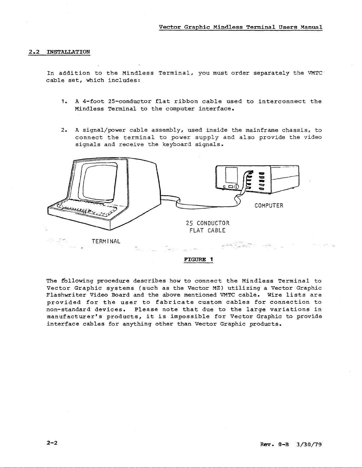
In
addition
cable
1.
2.
set,
A
4-foot
Mindless
A
signal/power
connect
signals
to
which
the
Mindless
includes:
25-conductor
Terminal
cable
the
terminal
and
receive
to
the
assembly,
the
Terminal,
flat
computer
to
power
keyboard
ribbon
used
supply
signals.
you
must
cable
interface.
inside
used
and
order
the
also
separately
to
interconnect
mainframe
provide
COMPUTER
the
chassis,
the
VMTC
the
to
video
The
fbllowing
Vector
Flashwriter
provided
non-standard
manufacturer's
interface
Graphic
TERMINAL
procedure
Video
for
the
devices.
cables
systems
Board
user
products,
for
anything
describes
(such
and
the
to
Please
it
how
as
the
above
fabricate
note
is
impossible
other
25
FLAT
FIGURE 1
to
connect
Vector
mentioned
that
than
Vector
CONDUCTOR
CABLE
the
MZ)
utilizing
VMTC
custom
due
to
for
Graphic
cables
the
Vector
Mindless
cable.
for
large
products.
a
Vector
Wire
connection
variations
Graphic
Terminal
Graphic
lists
to
provide
to
are
to
in
2-2
Rev.
O-B
3/30/79
Page 11
Vecto:=
Grc.ohic
Mir_dle!:s
Termir3.1
Users
Man-.ral
VIDEO
CONNECTOR
" , .
ll
I"'i
il
""',1
I
-;
I I
I
I'
.....
'
""',
'"l::r'
"
II
',J
'/.
(
,ii;lililll'!::
III
\\\\I \
I
f
TT
1\
\1;,\\
I;
I
r--
l~
I
..
""':l"'
~~"
I
NTERFACE
C
ONNECTOR
, .
...
.
',
KEYBOARD
CONNECTIONS
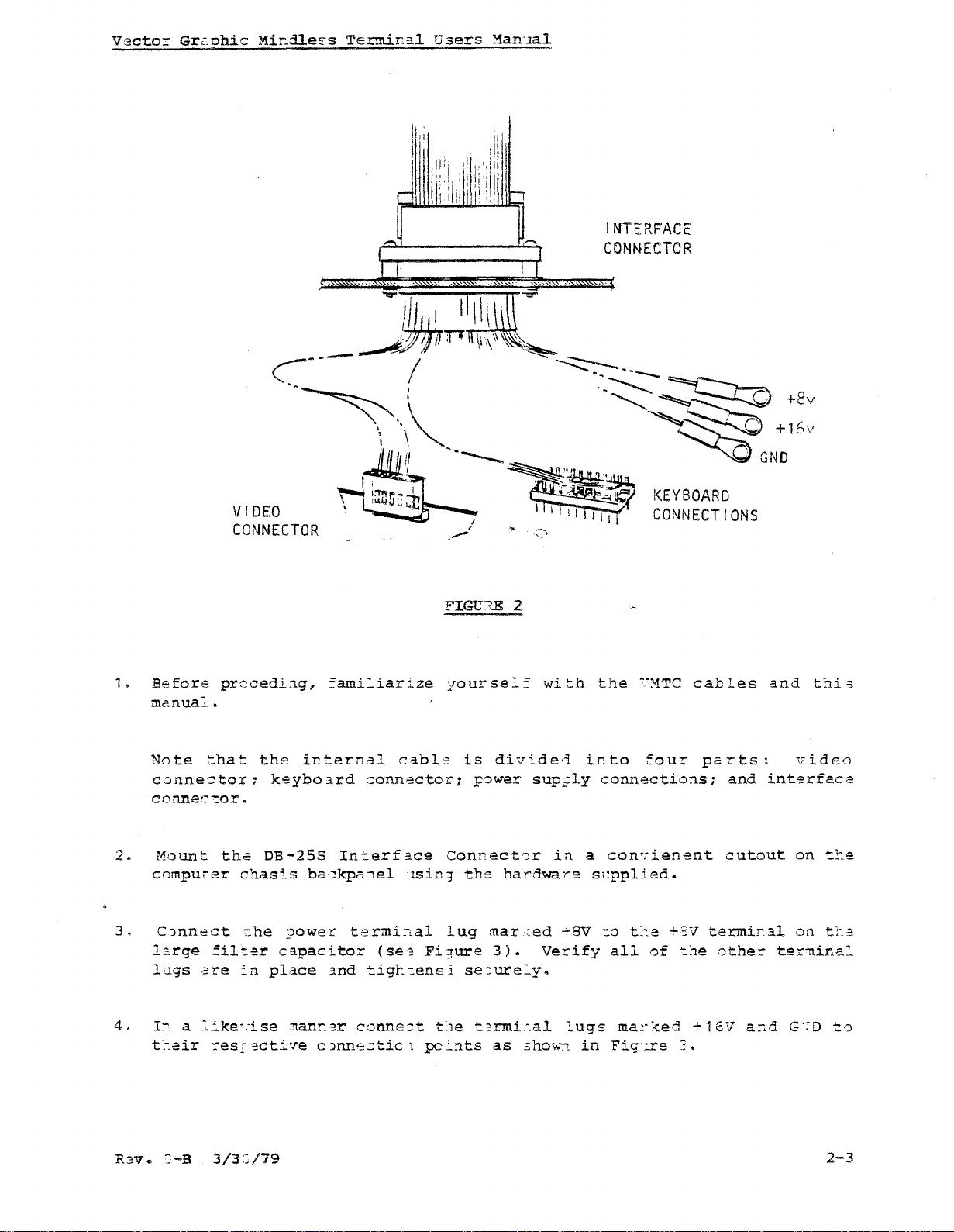
1.
Before
manual.
Note
cQnne~tor;
Connec-:.or.
2.
rl<Junt
computer
3.
C)nnect
L:.rge
lugs
4.
In
a
t::eir
preceding,
:.hat
the
chasis
"he
filter
ere
in
::'ike"ise
::oes::-
the
internal
keybo~rd
DB-25S
ba::kpa:1el
?ower
capacitor
place
:!1.anr.er
ecti'.re
::amiliarize
connector;
Interfa.ce
terminal
and
tigt~enei
conne:::t
c)nne:::tic
cabl,,;;
(se?
FIGD'?"E 2
yoursel::
Connect'Jr
LlSin~
lug
Fi~ure
t:1e
1
p::ints
wi::.h
is
divide,j
Fower
the
se::ure~y.
t?rmi~al
sup?ly
in
hardware
mar~~ed
3).
as
Verify
.3how'":"l
the
into
a
s1..:.pplied.
.:..8V
lugs
in
c-:'1TC
four
connections;
con'lienent
to
t::e
+sv
all
of
ma~.,<ed
Fig'.:.re:.
cables
':one
+
parts:
and
cutout
terminal
other
16V
and
interface
and
thi
video
on
t1::.e
on
the
ter-nin.::.l
G'm
'3
to
R3V
..
J-B
3/3:=/79
2-3
Page 12
Vector
Graphic
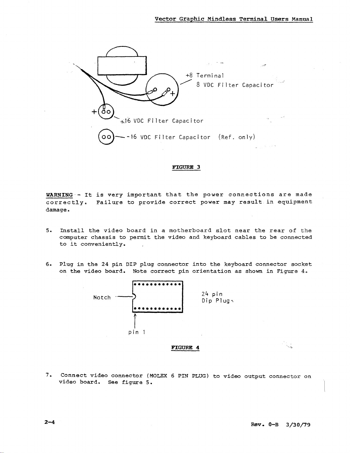
+8
~
Mindless
Terminal
8
VDC
Filter
Terminal
Capacitor
Users
Manual
WARNING·correctly.
damage.
5.
Install
computer
to
it
6.
Plug
on
the
8--16
is
It
Failure
the
video
chassis
conveniently.
in
the
24
video
Notch
--hJ'6
very
pin
board.
VDCFiIter
VDC
important
to
provide
board
to
permit
DIP
plug
Note
••••••••••••
••••••••••••
Filter
in
a
the
connector
correct
Capacitor
Capacitor
FIGURE
that
motherboard
video
the
correct
and
pin
3
power
power
slot
keyboard
into
orientation
24
Dip
the
pin
PI
(Ref.
connections
may
near
cables
keyboard
as
ug
",
only)
result
shown
in
the
rear
to
be
connector
in
are
made
equipment
of
connected
socket
Figure
the
4 •
7.
2-4
Connect
video
video
board.
connector
See
figure
pin
FIGURE 4
(MOLEX6PIN
5.
PLUG)
to
video
output
Rev.
"..,,:>-
connector
O-B
3/30/79
on
Page 13
Vector
GraEhic
Mindless
Terminal
Users
Manual
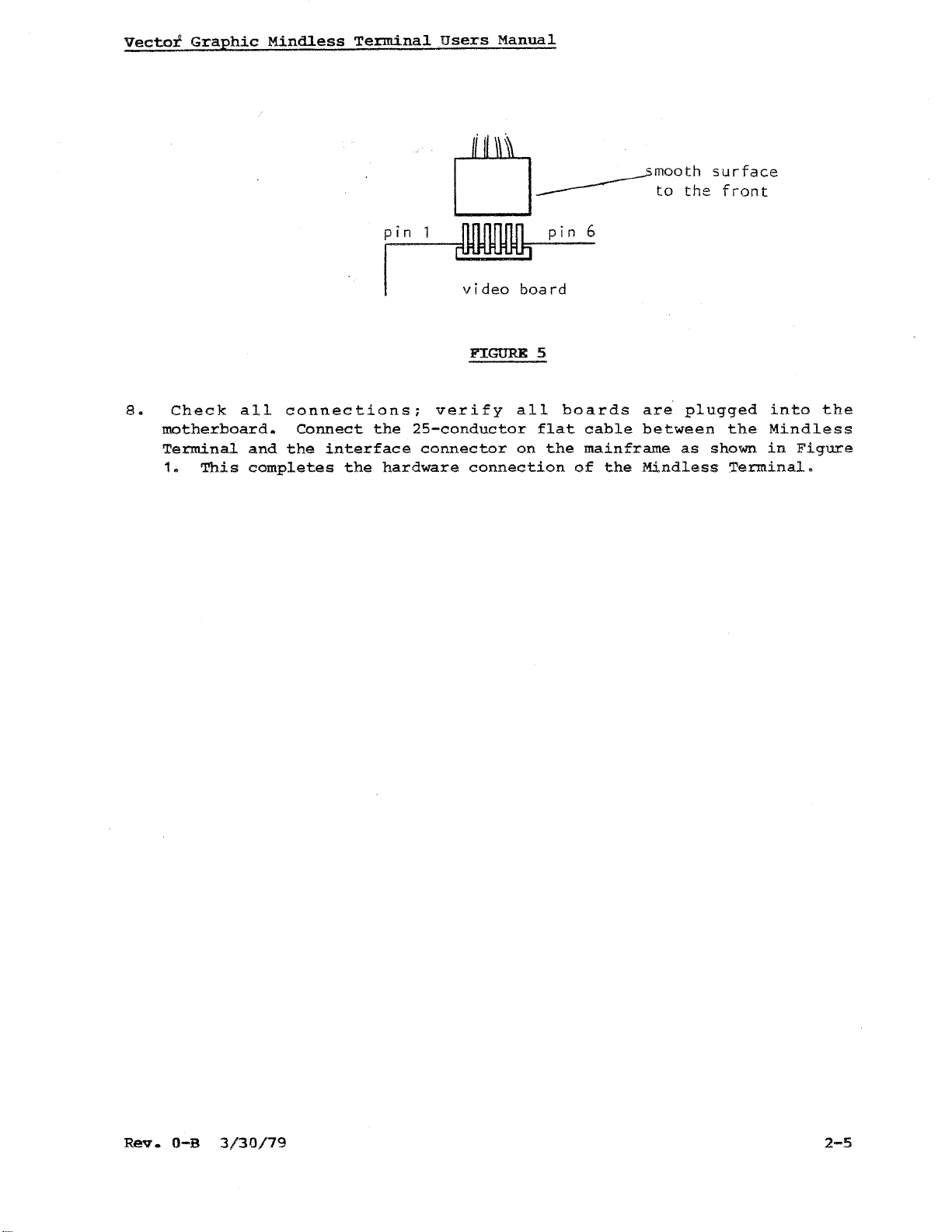
8.
motherboard.
Terminal
1.
Check
This
all
connections;
and
the
completes
Connect
interface
~
LJ-----
pin pin
video
FIGURE 5
verify
the
25-conductor
connector
the
hardware
connection
board
all
flat
on
boards
the
----,mooth
6
cable
mainframe
of
the
to
the
are
plugged
between
as
Mindless
surface
front
the
shown
Terminal.
into
Mindless
in
Figure
the
Rev.
O-B
3/30/79
2-5
Page 14
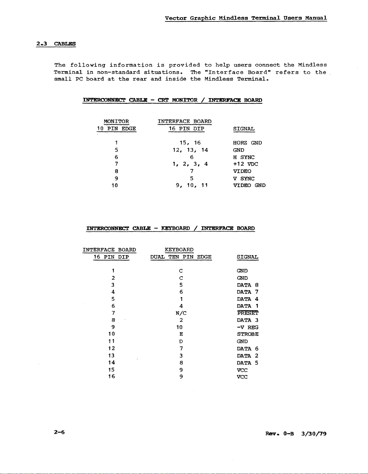
2.3
CABLES
The
following
Terminal
small
PC
in
non-standard
board
information
at
the
rear
Vector
is
situations.
and
inside
provided
Graphic
to
The
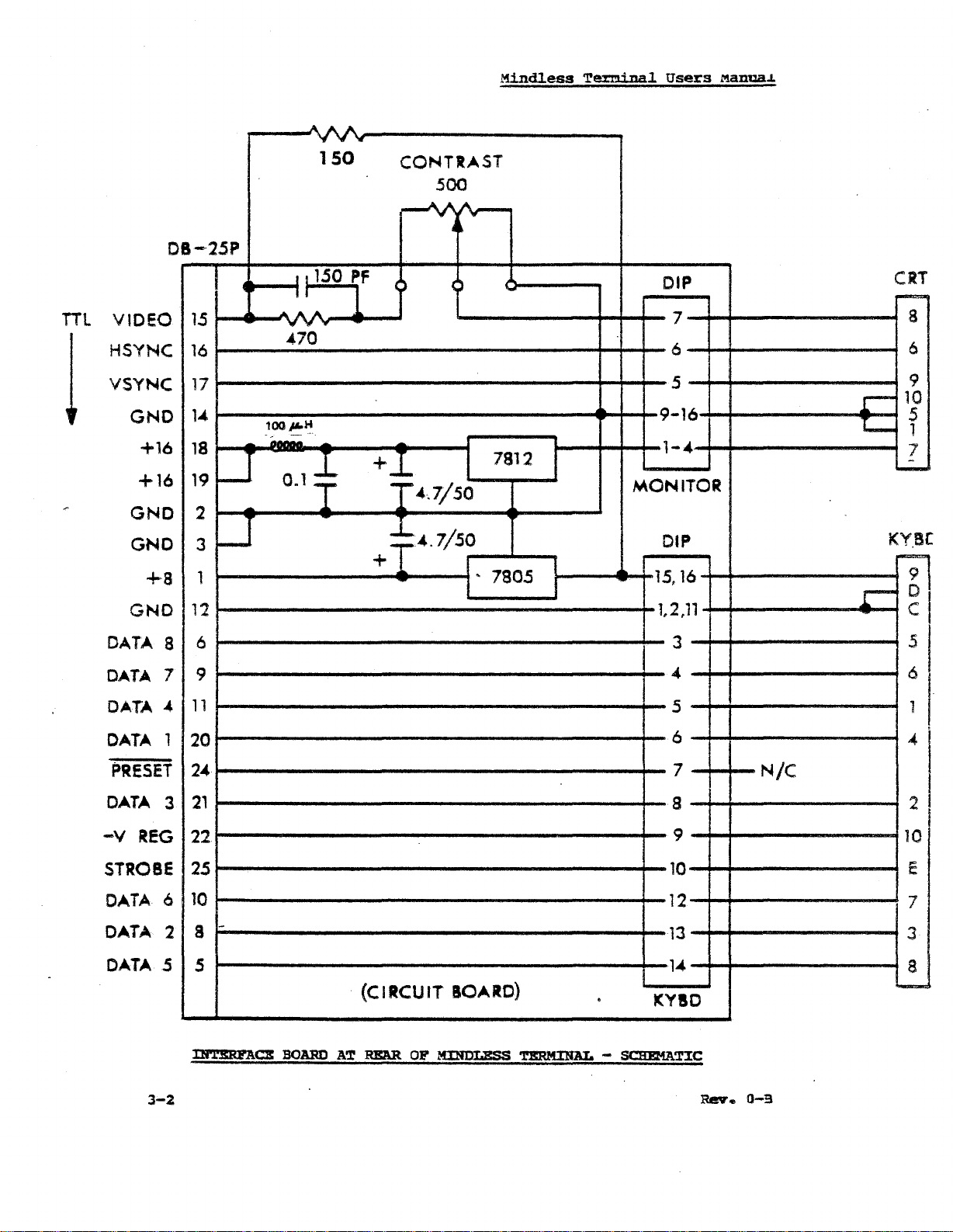
"Interface
the
Mindless
Mindless
help
Terminal
users
Board"
Terminal.
connect
Users
the
refers
Manual
Mindless
to
the
INTERCONNECT CABLE - CRT MONI'l'OR I
MONITOR
10
PIN
EDGE
1
5
6
7
8
9
10
INTERCONNECT CABLE -
INTERFACE
16
PIN
BOARD
DIP
1
INTERFACE
16
PIN
15,
BOARD
DIP
16
12, 13,
6
2,
1,
9,
:K:EY'BOARDIINTERFACE
3,
7 VIDEO
5
10,
KEYBOARD
DUAL
TEN
PIN
EDGE
C
2 C
3 5
4
5 1
6 4
7
8
9
10
11
12
13
14
15
16
6
N/C
2
10
E
D
7
3
8
9 vee
9 vee
INTERFACE
BOARD
SIGNAL
HORZ
14
4
GND
H
SYNC
+12
V
SYNC
11 VIDEO
BOARD
SIGNAL
GND
GND
DATA
DATA
DATA
DATA
PRESET
DATA
-V
STROBE
GND
DATA
DATA
DATA
GND
VDC
GND
8
7
4
1
3
REG
6
2
5
2-6
Page 15
Vector
Graphic
Mindless
Terminal
Users
Manual
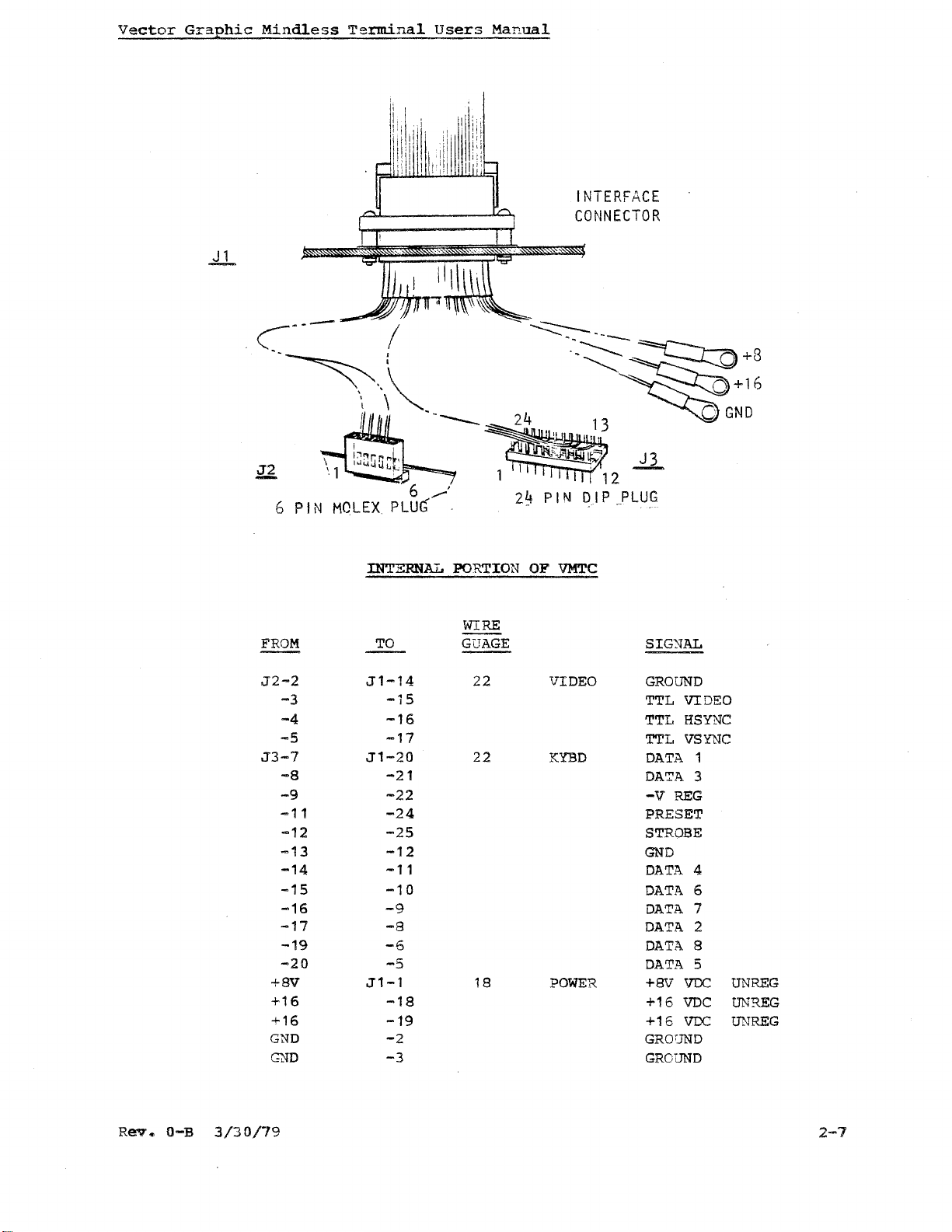
INTERFACE
CONNECTOR
6
FROM
J2-2
-3
-4
-5
J3-7
-8
-9
-11
-12
-13
-14
-15
-16
-17
-19
-20
+8V
+16
+16
GND
~D
PIN
6
___
MOLEX
PLU'
:INTERNAL PORTION OF
WIRE
TO
J1-14
GUAGE
-IS
-16
-17
J1-20
-21
-22
-24
-25
-12
-11
-10
-9
-8
-6
-5
J1-1
-18
-19
-2
-3
22
22
18
VMTC
VIDEO
KYBD
POWER
SIGNAL
GROUND
TTL VIDEO
TTL
HSYNC
TTL
VSYNC
DATA
DA':'A
-V
PRESET
STROBE
GND
DATA
DATA
DATA
DATA
DATA
DATA
+8V VDC
+16
+16
GROUND
GROUND
1
3
REG
4
6
7
2
8
5
VDC
VDC
UNREG
UNR.EG
UNREG
Rev.
0-13
3/30/79
2-7
Page 16
Vector
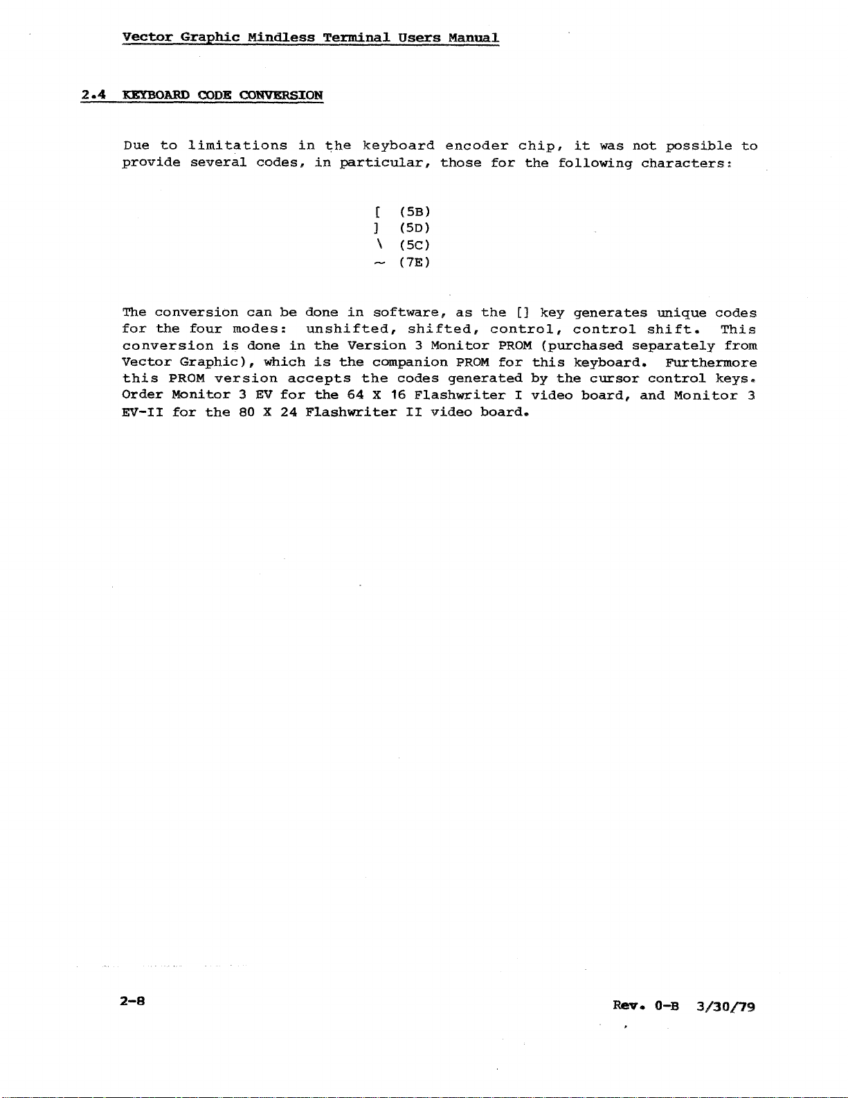
2.4
KEYBOARD CODE CONVERSION
Due
provide
The
for
conversion
Vector
this
Order
EV-II
Graphic
to
limitations
several
conversion
the
four
Graphic),
PROM
Monitor
for
the
is
version
Mindless
codes,
can
modes:
done
which
3
EV
80X24
in
be
done
unshifted,
in
accepts
for
Flashwriter
Terminal
the
in
particular,
in
the
Version
is
the
the
64
Users
keyboard
(
(SB)
]
(SD)
\
(SC)
(7E)
software,
companion
the
codes
X 16
II
Manual
encoder
those
as
shifted,
3
Monitor
PROM
generated
Flashwriter
video
for
the
control,
PROM
for
board.
chip,
the
[]
key
(purchased
this
by
I
video
it
was
following
generates
control
keyboard.
the
cursor
board,
not
possible
characters:
unique
shift.
separately
Furthermore
control
and
Monitor
to
codes
This
from
keys.
3
2-8
ReY.
O-B
3/30/79
Page 17
Vector
Graphic
Mindless
Terminal
Users
Manual
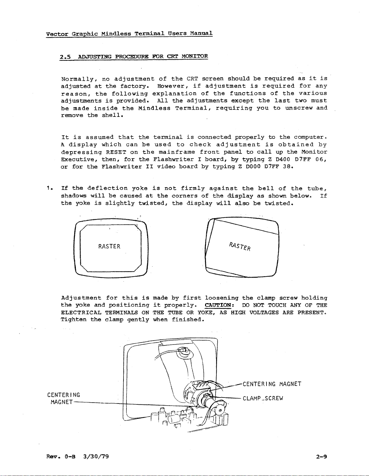
2.5
1.
ADJUSTING
Normally,
adjusted
reason,
adjustments
be
made
remove
It
is
assumed
A
display
depressing
Executive,
or
for
the
If
the
deflection
shadows
the
yoke
at
the
inside
the
will
is
PROCEDURE
no
adjustment
the
factory.
following
is
provided.
the
shell.
that
which
RESET
then,
Flashwriter
slightly
be
can
for
caused
Mindless
the
be
on
the
yoke
twisted,
FOR
of
However,
explanation
All
terminal
used
the
mainframe
Flashwriter
II
video
is
at
the
CRT
the
the
not
corners
the
MONITOR
CRT
if
adjustments
Terminal,
is
to
check
board
firmly
display
screen
adjustment
of
the
requiring
connected
adjustment
front
I
board,
by
typing
against
of
the
will
should
functions
except
properly
panel
by
display
also
to
typing
Z
0000
the
be
is
be
required
required
the
you
is
call
07FF
bell
as
twisted.
of
last
to
to
the
obtained
up
Z
0400
of
shown
the
two
unscrew
computer.
the
07FF
38.
the
below.
as
it
for
various
must
Monitor
tube,
is
any
and
by
06,
If
Adjustment
the
ELECTRICAL
Tighten
CENTERING
MAGNET---
yoke
RASTER
and
the
clamp
for
this
positioning
TERMINALS
gently
l
is
ON
made
it
THE
when
by
first
properly.
TUBE
finished.
OR
YOKE,
n2!t't-------
loosening
CAUTION:
AS
RASTeR
the
00
HIGH
VOLTAGES
--CENTERI
CLAMP
clamp
NOT
screw
TOUCH
NG
MAGNET
_SCREW
ANY
ARE
holding
OF
THE
PRESENT.
Rev.
O-B
3/30/79
2-9
Page 18
Vector
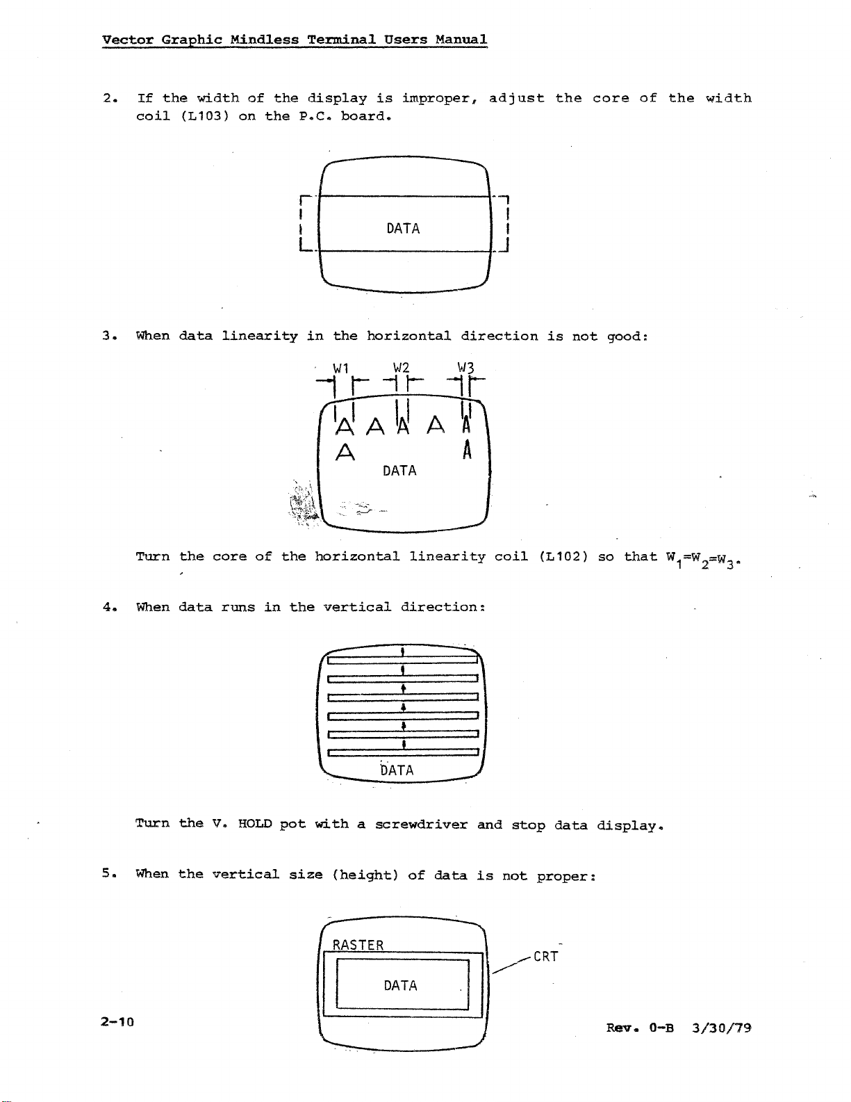
2.
3.
If
coil
When
Graphic
the
width
(L103)
data
Mindless
of
on
linearity
Terminal
the
display
the
P.C.
board.
r·f---------~-.,
Users
is
improper,
I I
I
DATA
L.
in
the
horizontal
Manual
direction
adjust
I
_J
the
core
is
not
good:
of
the
width
4.
Turn
When
the
data
core
runs
of
in
II""1r
the
horizontal
the
vertical
r==
Wl
\>J2
WA
DATA
direction:
t
+
!
tiATA
1,
linearity
IfJ3
lA'
A
coil
(L102)
so
that
W1=W
2=w3
•
5.
2-10
Turn
When
the
the
V.
HOLD
vertical
pot
size
with
(height)
a
screwdriver
of
data
and
is
II
stop
not
~CRT
data
proper:
display.
Rev.
O-B
3/30/79
Page 19
Vector
Graphic
Mindless
Terminal
Users
Manual
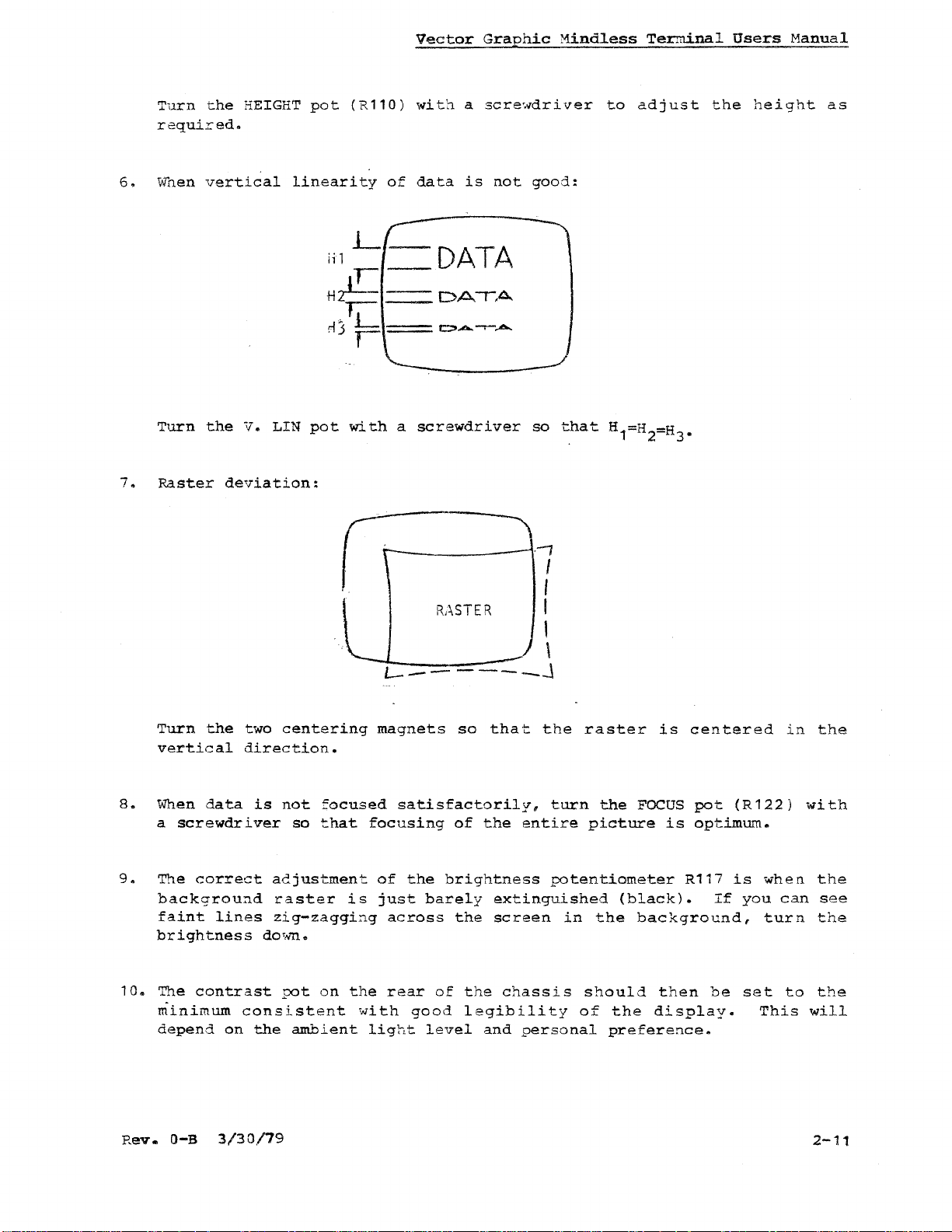
6.
7.
Turn
required.
wnen
Turn
Raster
the
vertical
the
HEIGHT
V. LIN
deviation:
pot
(R110)
linearity
jilL-DATA
,-
Hzl!--
~--
rlj
F=
pot
with
with
of
data
-
a
screwdriver
a
screwdriver
is
not
good:
DA~A.
CO_-·-:,b,.
,
so
that
to
adjust
H1=H2=H
the
height
•
3
as
Turn
vertical
8.
When
a
screwdriver
9.
The
backgrou~d
faint
brightness
10.
The
minimum
depend
the
data
correct
lines
contrast
on
two
centering
direction.
is
not
focused
so
that
adjustment
raster
zig-zaggi~g
dO'Nn.
pot
on
consistent
the
ambient
rt=-~
RASTER
-l·7
I
I
\
L-------J
magnets
focusing
is
the
with
light
satisfactorily,
of
the
just
across
rear
good
so
of
brightness
barely
the
of
the
legibility
level
that.
the
extinguished
screen
and
the
turn
entire
potentiometer
chassis
personal
raster
in
should
of
the
picture
(black).
the
the
preference.
is
centered
FOCUS
background,
pot
is
optimum.
R117
then
display.
be
If
(R122)
is
when
you
turn
set
This
in
can
to
the
with
the
see
the
the
will
Rev.
O-B
3/30/79
2-11
Page 20
11.
The
control
the
horizontal
and
Flashwriter
positioning
also
the
board.
Vector
is
position
The
controlled
control
latter
Graphic
is
the
Mindless
by
on
the
preferred
both
the
upper
Termina1
video
left
adjustment.
Users
CENT
hand
Manua1
(A103)
corner
of
2-12
Page 21
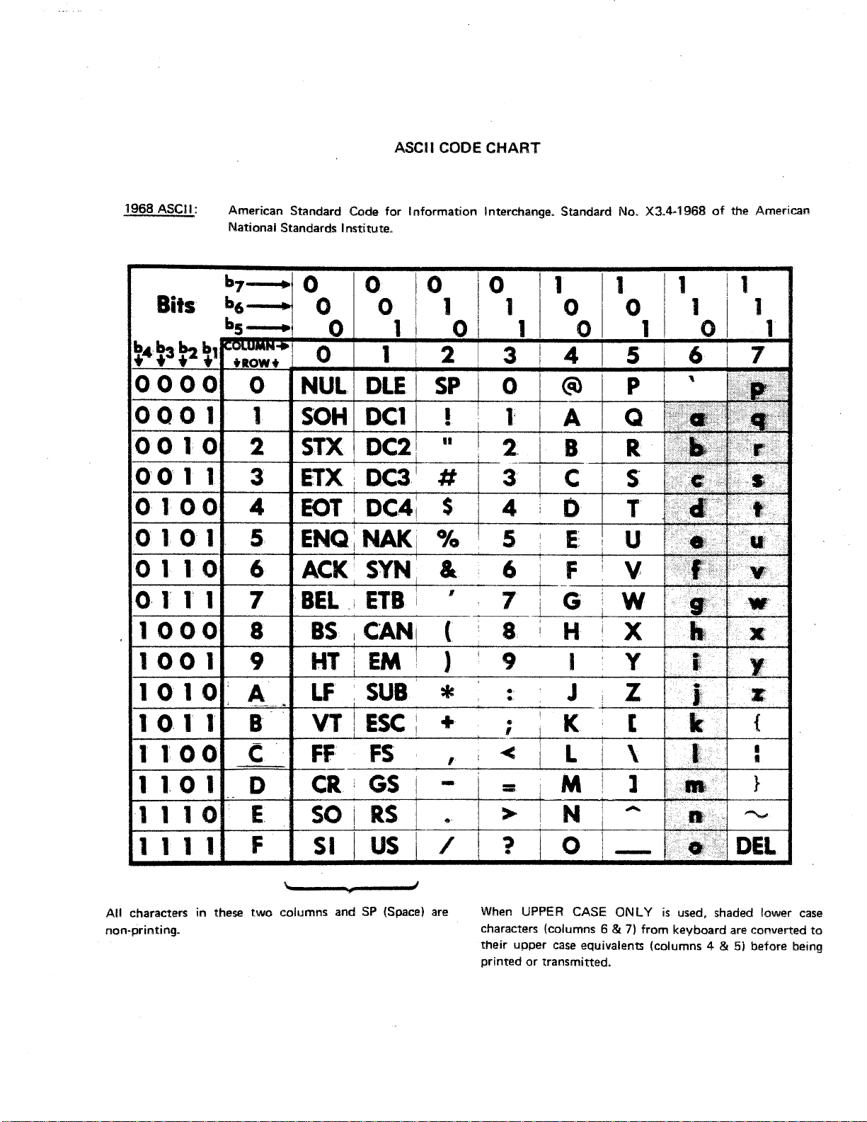
ASCII CODe
1968
ASCII: American Standard Code for Information Interchange. Standard No. X3.4·1968ofthe American
National Standards Institute.
CHART
b7---·_
Bits
~4~3~
b,
bs
~1
tROW + 0 1 2 4
o0 0 0 0
0001
001.0
00
o
1 1 3 ETX,
1.
0 0 4
1
2
o 1 0 1 5
01106
1-----11-----4----!---4------_+_
0,
1
1.
1 1
1000
1001
8
9
1
0 0 0 0 1
0 0 1 0
II
0 1 0 0
NUL
SOH
STX
EOT
ENQi
DLE
DC1!
DC2,
DC3
I
DC41
NAK
SP
II
1
# C
$ D
ACKSYN
BEL,IETB
BS
leAN
i G
( H
HTiEM!)
@)
A
B
-t---
E:
F
I
1010:A
1011
I-----II------I---'-----'------l--'-+-----t----+-----"""'""--+---I
1
l'
I-=---=--=-~---====-I--
I------II-----I---f---f------j----r--
00
11.0
1110
IOCR
B VT
C
E,
1 I t 1 F
All
charactersinthese
non-printing. characters (columns 6
two
LF
FF
SORS
SI
columns and SP (Space) are When UPPER CASE ONLYisused, shaded lower case
SUB
ESC:,
FS
GS
US
* : J
+
'
- = M
..
/ ? 0
..
K
< L
> N
their upper case equivalents (columns 4 &5)before being
printed or transmitted.
--+-----I~*'±++++--___I
-
&
7)
from keyboard are converted
•
•
}
DEL
to
Page 22

Page 23
A
150
...
CONTRAST
500
Mindless
Terminal
Users
Manua~
TTL
I
VIDEO
HSYNC
VSYNC
OND
+16
+16
GND
GND
+8
GNO
DATA 8
o
B-·25P
1.5
16
17
1.4
18
19
2
3
1
12
6
- "
.-.I
-
.-.I
£
.470
100 .....
..
-
0.1
I I
II
1.50
1-1
..L
T
~tv-
A~
PF
()
.L
".
-
+.1
-~.4.7/.50
<)
7812
+y".7/50.
780.5
DIP
7
6
.5
9-16
1-.4
MONITOR
DIP
1.5,
16
1,2,11
3
CRT
r"'""""'"
8
6
9
10
r-
"L-.
5
1
7
-
KY,BC
r~
.5
DATA 7
DATA
DATA 1
PRESET
DATA
-v
REG
STROBE
DATA
DATA 2
DATA.5
3-2
9
11
.4
20
24
21
3
22
25
10
6
8 -
S
IN"l'kRJ!'AO BOARD AT REAR
(CIRCUIT 80ARD)
OP
MDI'DLESS 'l'ERKINAL - SCBEMA'l'J:C
...
5
6
7
N/C
6
1
-4
a 2
9
10
12
13
14
.
KVBO
Reve
Q-B
10
E
7
3
8
--
Page 24

Page 25
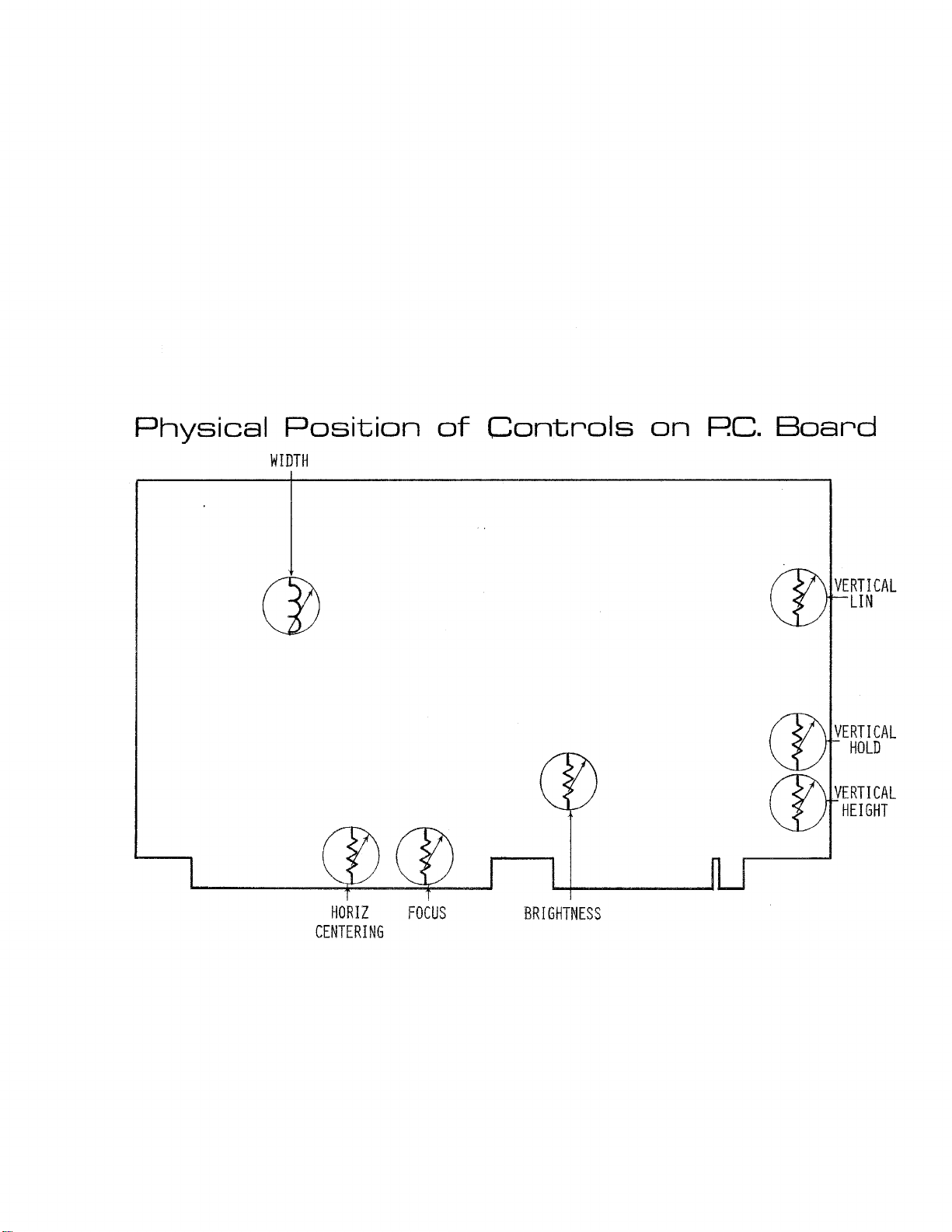
Physical
Position
WIDTH
of
Controls
on
Re.
Board
VERTICAL
LIN
VERTICAL
HOLD
VERTICAL
HEIGHT
HORIZ
CENTERING
FOCUS
BRIGHTNESS
Page 26

Page 27
-l/1V (i7')-
T
CD"
~~LC
I
0.-
r..~--
.1
27,
••
'i~;:
....,;;I.;;:V,,;-_4_-..._~
INPut
C33
4700MFOr
,"V
BflITE
T
••
10M
.!~
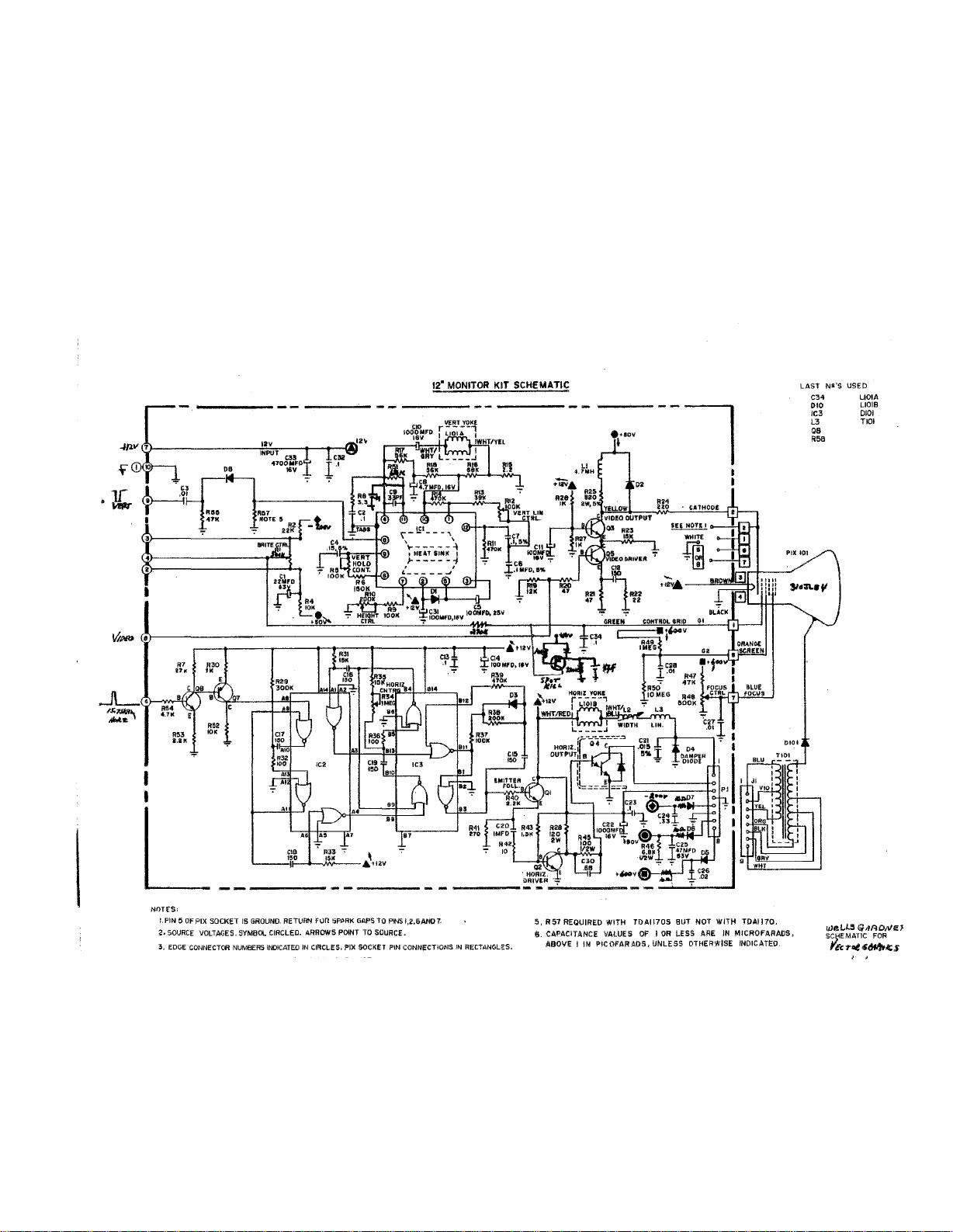
12"
MONITOR KIT SCHEMATIC
--'=!..-
__
+-...J,
LAST
N5I'S
C34
010
IC3
L3 TIOI
QB
A5a
USED
L101A
L101B
0101
..JL~."
~~
....
~~
I
I
L
NOTES:
l.PIN5OF
2.
3.
_·.Ly
.53
I.Ut
PIX
SOCKET
VOLTAGES.
IS GROUND. RETURN
5YMBOl
SOURCE
EDGECONNECTCR NUMBERS
Fun
IN CIRCLES.
!iPftRK GAPSTOPINS
PIX
SOCKEl
PIN CONNECTiONS
CIRCLED. ARROWS POINT TO SOURCE.
INDICATED
1,2.6AN07.
1"1
RECTANGl;!S.
0,
R51
REQUIRED WITH
S.
CAPACITANCE VALUESOFlOR
ABOVE IINPIC
OFA/HOS
TDA1I70S
BUT NOT WITH TOA1170,
LESS
, UNLESS OTHERWISE INDICATED
AREINMICROfARADS,
0101
weL~~
S~)iEMATJC
'Fc:l"ot~~~s
<';,fFlONel
FOR
Page 28

Page 29
SPECIFI
s
MODEL CIQ-9
MODEL CIQ-12
g"and
DISP
-<aE
c.
12"
o
ITOH ELECTRONICS, INC.
5301
Beethoven
TelephOne:
Telephone: (212) 682-0420 Telex (WU) 12-5059
IT·
Street
Los
(213) 390-7778
280 Park
."venue. New York. NY 10017
Angeles.
Telex:
T
Calif.
90066
(WU) 65-2451
Page 30

Page 31
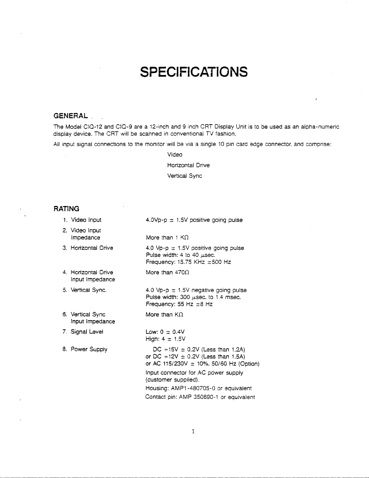
GENERAL
SPECIFICATIONS
The Model
display device. The CRT will
All
input signal connectionstothe monitor will be via a single10pin card edge connector, and comprise:
C1Q-12
and C1Q-9 are a 12-inch and 9 inch CRT Display Unit istobe usedasan
be
scannedinconventional TV fashion.
Video
Horizontal Drive
Vertical Sync
alpha-numeric
RAT1NG
1.
Video Input
2.
Video Input
Impedance
3.
Horizontal Drive
4.
Horizontal Drive
Input Impedance
5.
Vertical Sync.
4.0Vp-p
More than 1
4.0
Pulse width: 4
Frequency: 15.75 KHz :::500 Hz
More than
4.0 Vp-p::1.5V negative going pulse
Pulse width: 300
Frequency:
Vp-p
::t
1.5V positive going pulse
K.o
:::
1.5V positive going pulse
to40p.Sec.
470.0
,usee.
to1Amsec.
55Hz::
8 Hz
6.
Vertical Sync
Input Impedance
7.
Signal Level
8.
Power Supply
More than
Low: 0 =OAV
High: 4
DC
or DC
AC
or
Input connector for
(customer supplied).
Housing: AMP1-480705-0 or equivalent
Contact pin: AMP 350690-1 or equivalent
K.o
::
1.5V
-!-15V::0.2V (Less than 1.2A)
-!-12V=O.2V
115/230V::10%, 50/60 Hz (Option)
(Less than 1.5A)
AC
power supply
1
Page 32

Page 33
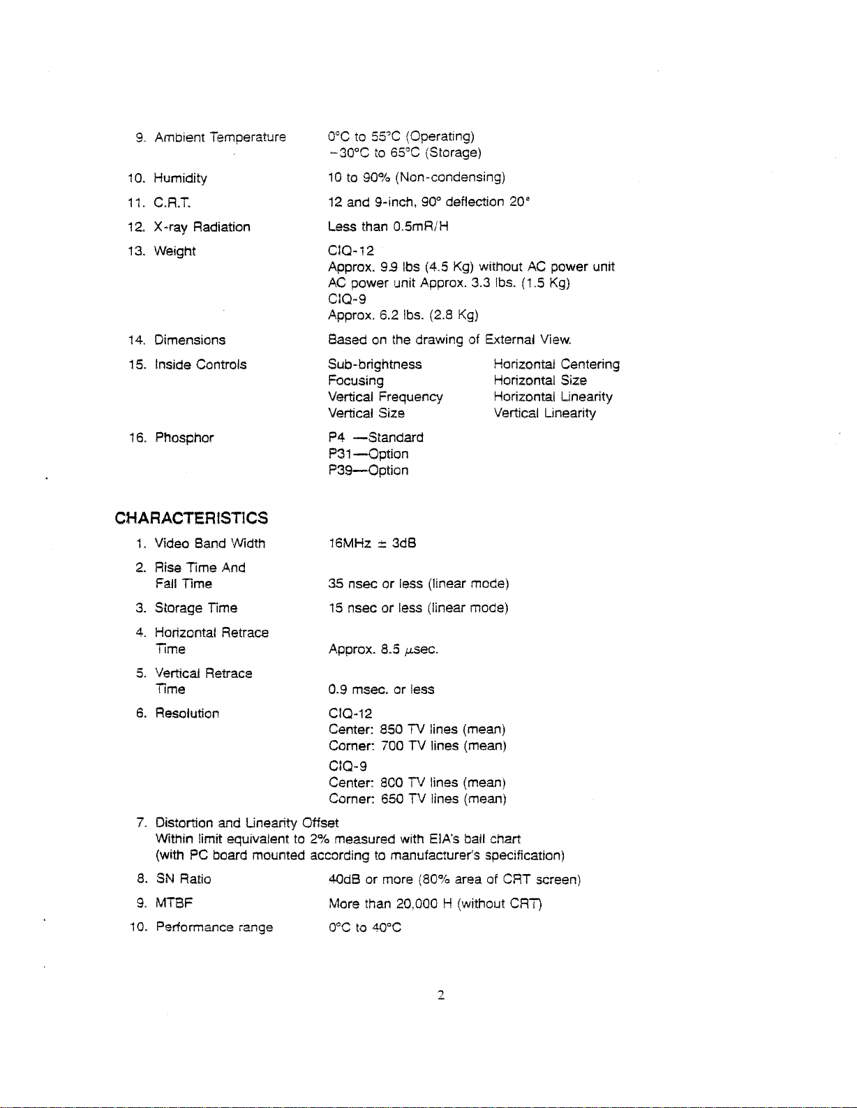
9,
Ambient Temperature
acc
to
~30°C
55?C
to
65°C
(Operating)
(Storage)
1a.Humidity
11.
C.A.T.
12.
X-ray Radiation
13.
Weight
14.
Dimensions
15.
Inside Controls
16.
Phosphor
CHARACTERlST1CS
Video Band Width 16MHz::3dB
1.
2.
Rise Time And
Fall Time
10to90% (Non-condensing)
12
and 9-inch,
Less than 0.5mA/H
CIQ-12
Approx.
AC
power unit Approx. 3.3
CIQ-9
Approx. 6.2
Basedonthe drawing of External
SUb-brightness Horizontal Centering
Focusing Horizontal Size
Vertical Frequency Horizontal Linearity
Vertical Size Vertical Linearity
P4
-Standard
P31-0ption
P39-0ption
35
nsec or less (linear mode)
900deflection 20·
9.9
Ibs
(4,5
Ibs.
(2.8
Kg)
Kg)
without
Ibs.
AC
(1.5
View.
power unit
Kg)
15
3.
Storage Time
4.
Horizontal Retrace
Time Approx. 8.5
5.
Vertical Retrace
Time
6.
Resolution CIQ-12
nsec or less (linear mode)
j.J.sec.
0.9 msec. or less
Center: 850 TV lines (mean)
Corner: 700 TV lines (mean)
CIQ-9
Center: 800 TV lines (mean)
Corner: 650 TV lines (mean)
7. Distortion and Linearity Offset
Within limit equivalent to
(with
PC
board mounted accordingtomanufacturer's specification)
8.
SN
Ratio 40dB or more (80% area of CAT screen)
9.
MTBF More than 20,000 H (without CRT)
10. Performance range
2%
measured with EIA's ball chart
2
Page 34

Page 35
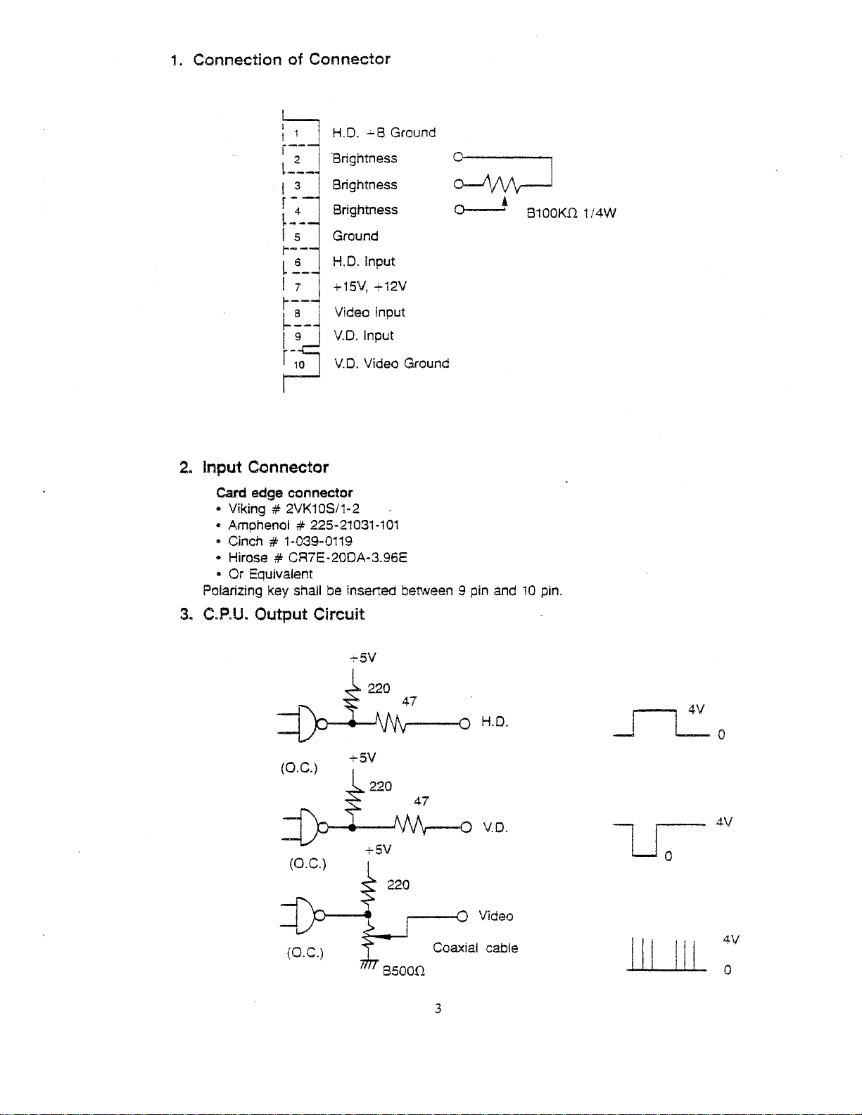
1.
ConnectionofConnector
~
r--
~--
I 3
r- -
~-
I 5
r--
L
I 7
r--
~~
I 9
r-
H.D.....B Ground
'Brightness
2
Brightness
Brightness
4
Ground
H.D. Input
~
+15V, +12V
Video Input
V.D.
V.D.
10
~
~
Input
Video Ground
2. Input Connector
Card edge connector
• Viking # 2VK10S/1-2
• Amphenol # 225·21031-101
• Cinch # 1-039-0119
• Hirose
• Or Equivalent
Polarizing key shall be inserted between 9 pin and
# CR7E·20DA-3.96E
B100K.f1
10
pin.
1/4W
3.
C.P.U.
Output
(0.
(0.
Circuit
C.)
C.)
+5V
220
H.O.
V.O.
Video
Coaxial cable
3
-u;-4V
Page 36

Page 37

TIMING CHART (Standard Type)
H.D.
Display
Blanking
Data Input
Signal
Horizontal
J-'·~lL..--_1
I I
I I
I I
iI Data
JJ
Blanking Time I I
I i
I1a.5 I Raster
111-
I,
I
39.0
55.0
(in
!LS)
(an'M
I
\i
~
I
I
Display
Blanking
v.O.
Vertical (in ms)
~
300
,.,-1'
I
I
I
I
I
I
l"ll.~
~Raster
I
I
I I I
!-+a.i9-,
Data Center
15.n
Lf
I
I
I
I
I
I
-I
I IAdjustable (:::3)1 I
I : I
I
I
I
I
I
I
~
I
I
I
D?~~y
----i
I 63.5
1-'----(1
1=0
H) I
-II
I
I
I
Data Input
Signal
I I I
I I
I
I
,
I
I
I
I
11-..----
I (1V)
1=0
~
Display
16.67
I
I
I
Data-1
14.4
I
I
---I
(15.75 KHz)
(60 Hz)
4
Page 38

Page 39
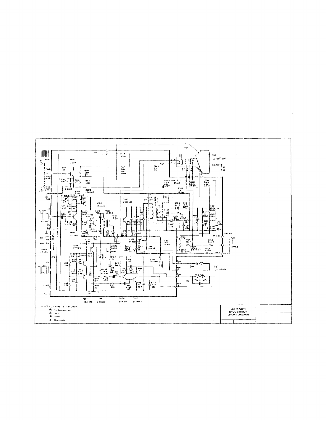
NaJ'::~:
I )
(e,
\.'IPUJ
•
'A
Il,lJlKf,1,Lf.u.>l'.IN!:.CTO"
PINU"J""'.fQft-
{lIHf-I;.l'
ADJl>.:;rEll
Qto"
l~AlO!5
qlOIlo
:Z~<lU)r5
CIQ-12
AND
9
15VOC VERSION
CInCUIT DtAGRAM
Page 40

Page 41
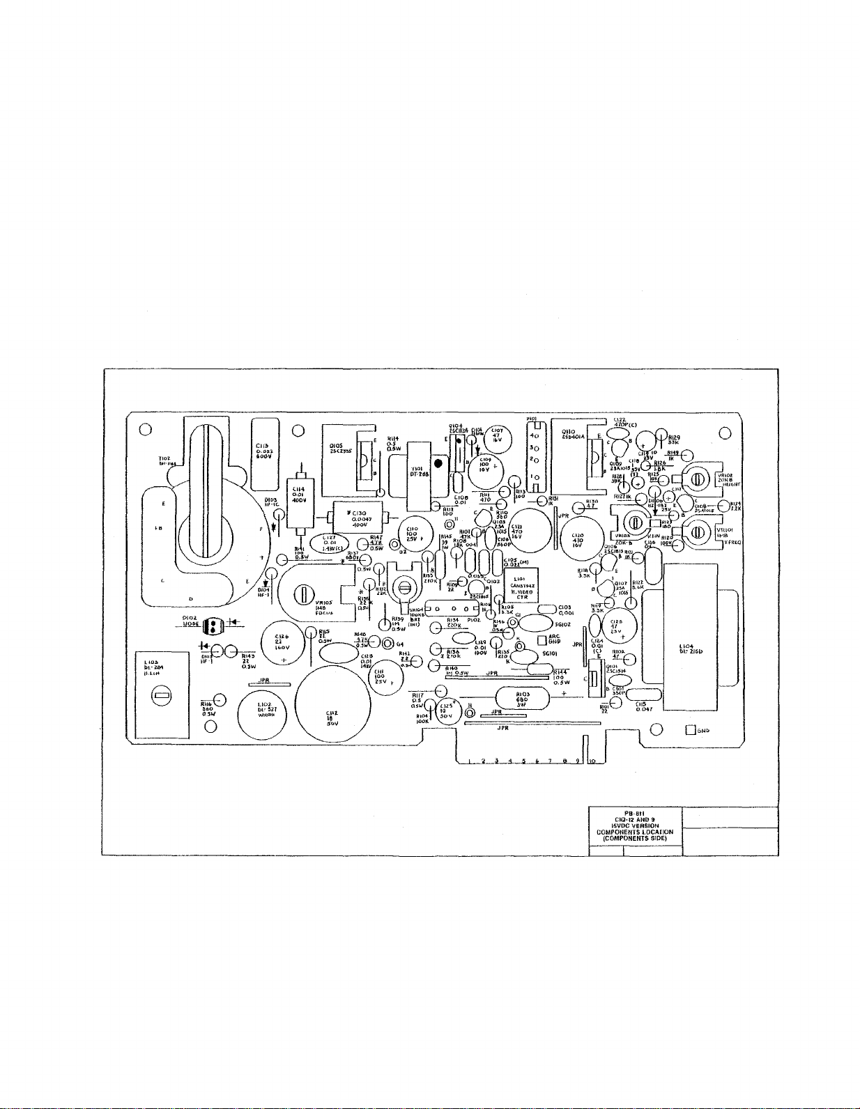
Po·au
CIQ-t2 AND 9
15VDC VERSION
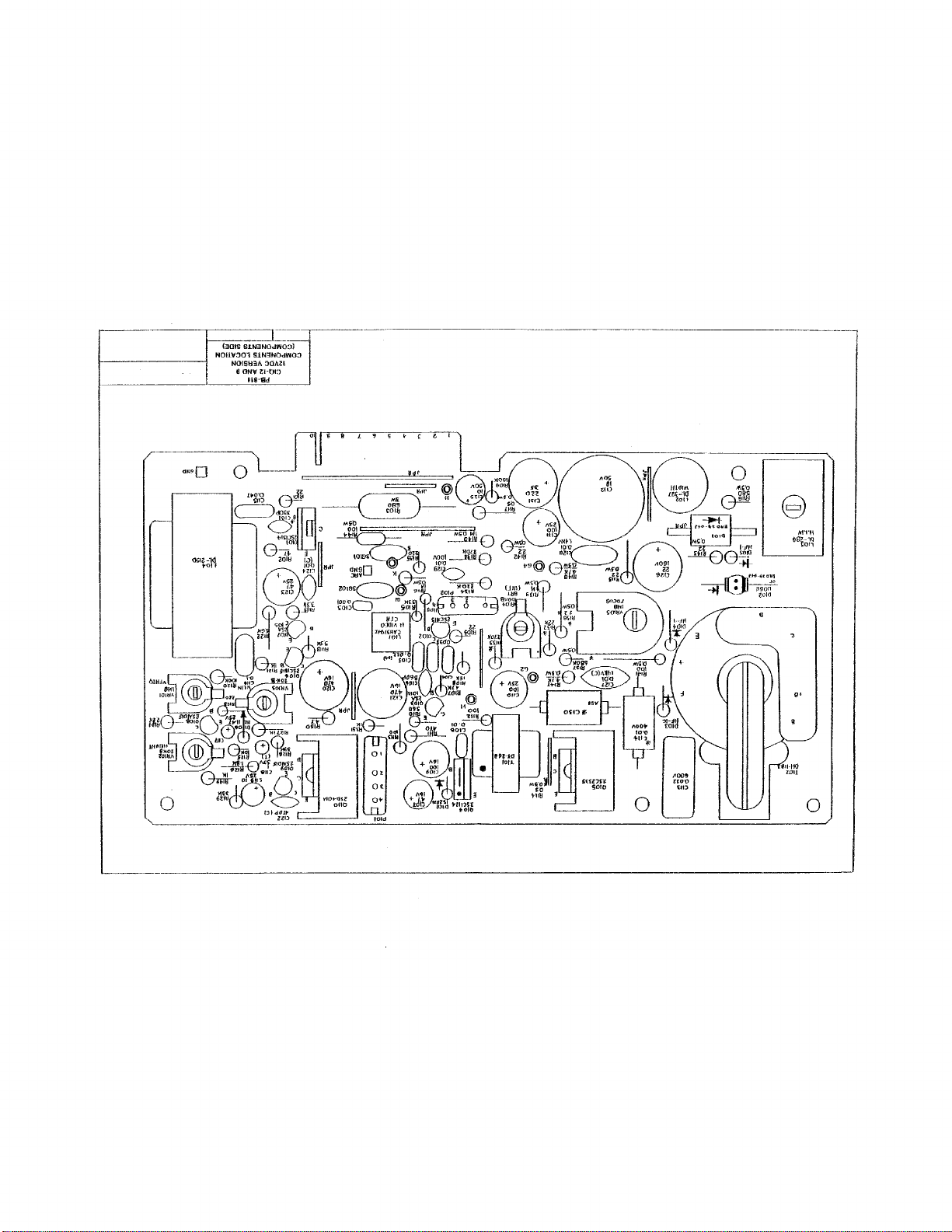
COMPONENTS lOCAl'JON
(COMPONENTS SIDE)
Page 42

Page 43
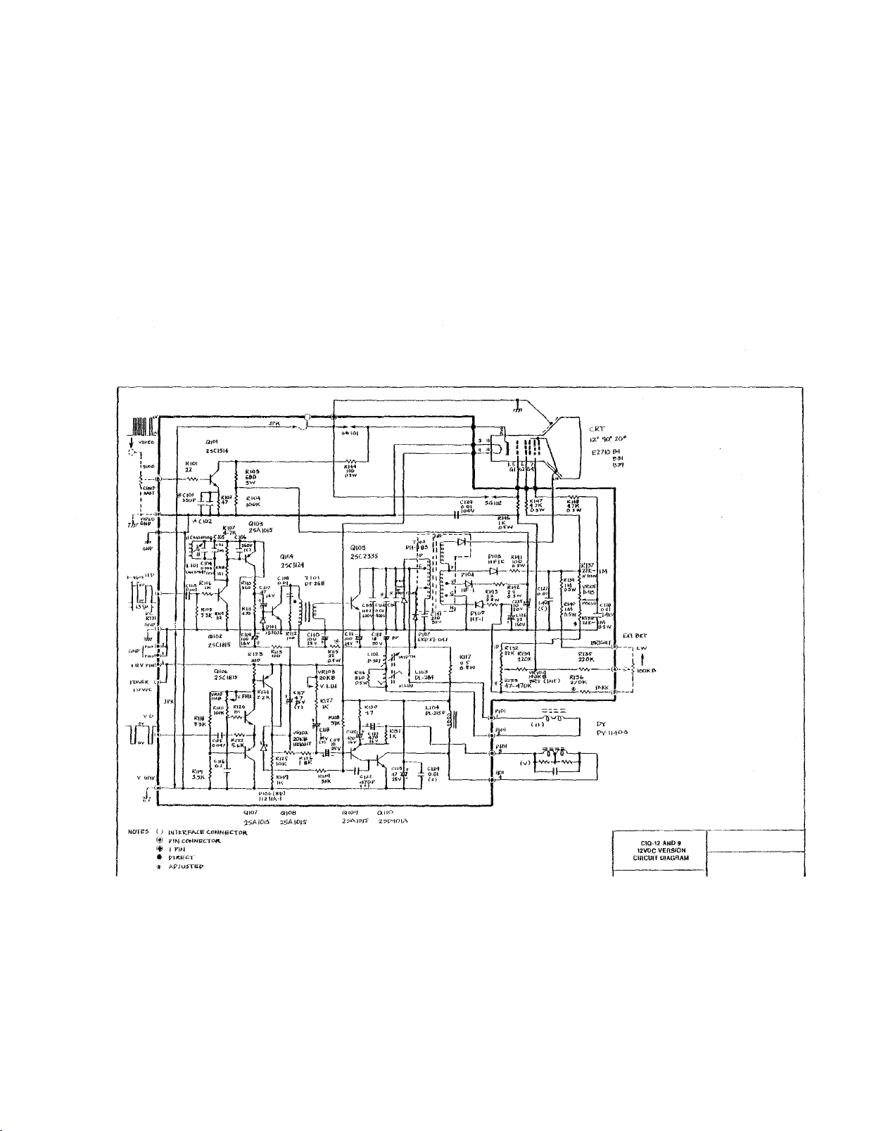
Hcrre~
()
mlt:.l::;Fr..£.E
@ jo'lf\j
ft1
I
p"u~
•
PIJ::~C..
,;.
ArJu;STe:v
(.oNNj:5CTOR
t:ONNE"GTQ(t,
1""101
:25AJDI~1
~loB
:.t.5AIDIS
6llOq
25AIDJ'j"
0.110
2?l/"-\OI;\
CRT
I;!~
E2110
'ld:
10"
~
."
B"
C1Q-12
AND
9
12VOC
VEnSION
CIRCUIT
OIAGRAM
Page 44

Page 45
Page 46

Page 47
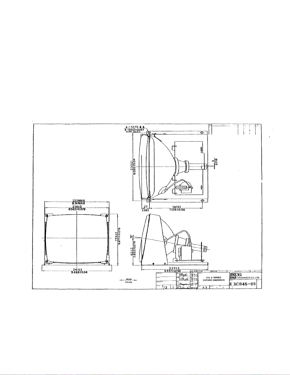
r-·----~----~~~u=-----.rJI~c-
...
-;;22MAli
8.74MA
1--------."'.6'iUt1rfg-------j
,...
-
Ml:ll
L
-------,,9.48iffll.04
.•
_
,
~3Q
__
llU!l~_
inch
~ClllJOM1l5l:::N
CO.ll.~
Page 48

Page 49
r
..
_---_.~
--=-~
ION
tON
90N
~Jl]~
~~iJv
~w
'ON
-~----~-
-.-------~
~
_.
.--
....,.,
(lsrOtLSllJU
....,.,
(l9n)ut01U
u~rO"'l!rUJ
"""'"
fLSIlHZ-tonll UIIt1.lttf39ln
"'"""
IL9t"OUU·.1I
"""'"
.....,
(lSilm.U1U
.....,
fl9(1):rZClUI
Il.!aOt098UJ
-
Ii"""
...
-JNn<IW
tUU'
.,08l
..
nez
U[8t
",Ui!'
t19'!1tit
...
e6t
t,tO£
"
'tf'Uf'WW.
_.,,"'--
ZlOIiZ
IIIUO'lSLBI
"Ironug-.)
'IUlJ:rU9r"81
IIHI'Olttnt
18UOJ~8111
(6t-OU,t>lU,1
ElLUl
UII:'Dll
uszz
E't-9lrt
Enu;z
18lfOt'I6l'8J (Gl.O'O'tUH
nt-Ell
fBlIUJlznl
nt..-r:z
£lszt
jfl:Loo:rtZnl
{GiO·Oter
IGl.OOt-S9SS'
(GlOn:rHttJ
ICLOO:rS99t-1
IGLO-OJOlS-.'
'I
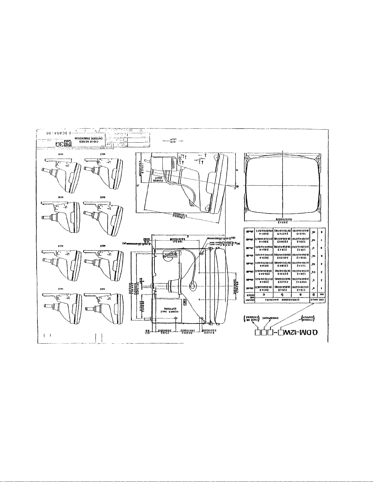
SNOlSN1WIO
Ut'!ll
nou
nSfl
Zl91Sl-
lUlL
UOtt
ZHi8U
nSt,
8
-
,s.
.0'
l
';-,,'
.0
.g.
.0'
~~n
.g
.0
9
1l!:Jm'1.3
//
~
•
,
•
9
•
t
•
I
'ON
l!~~~~:l~
Page 50

Page 51
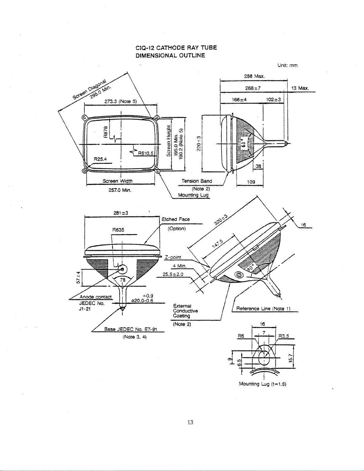
CIQ-12 CATHOOE RAY TUSE
DIMENSIONAL OUTLINE
-
iO
.Qj
S;~
:I:
~o
c
Ql
o~
~
LCiC\l
<.l
~g
(J)
.,..
C"l
~!
0
C\l
C\l
288 Max.
268::7
166:::4 102:::3
Unit: mrn
13
Max.
(Option)
Z-ooint
Tension Sand
(Note
Mounting
2)
Lug
Screen Width
257.0 Min.
281±3
Etched Face
R635
~;;;;;;;t;;j;;;;;;;;;;;~
4 Min.
25.5::2.0
"'0.9
020.0-0.6
Base JEDEC No. ::7-91
(Note
3.4)
External
Conductive
Coating
(Note
2)
Reference
R6
t.;L;=t
Une
16
(Note
A3.5
1)
13
~
Mounting
Lug
(t=1.6)
Page 52

Page 53
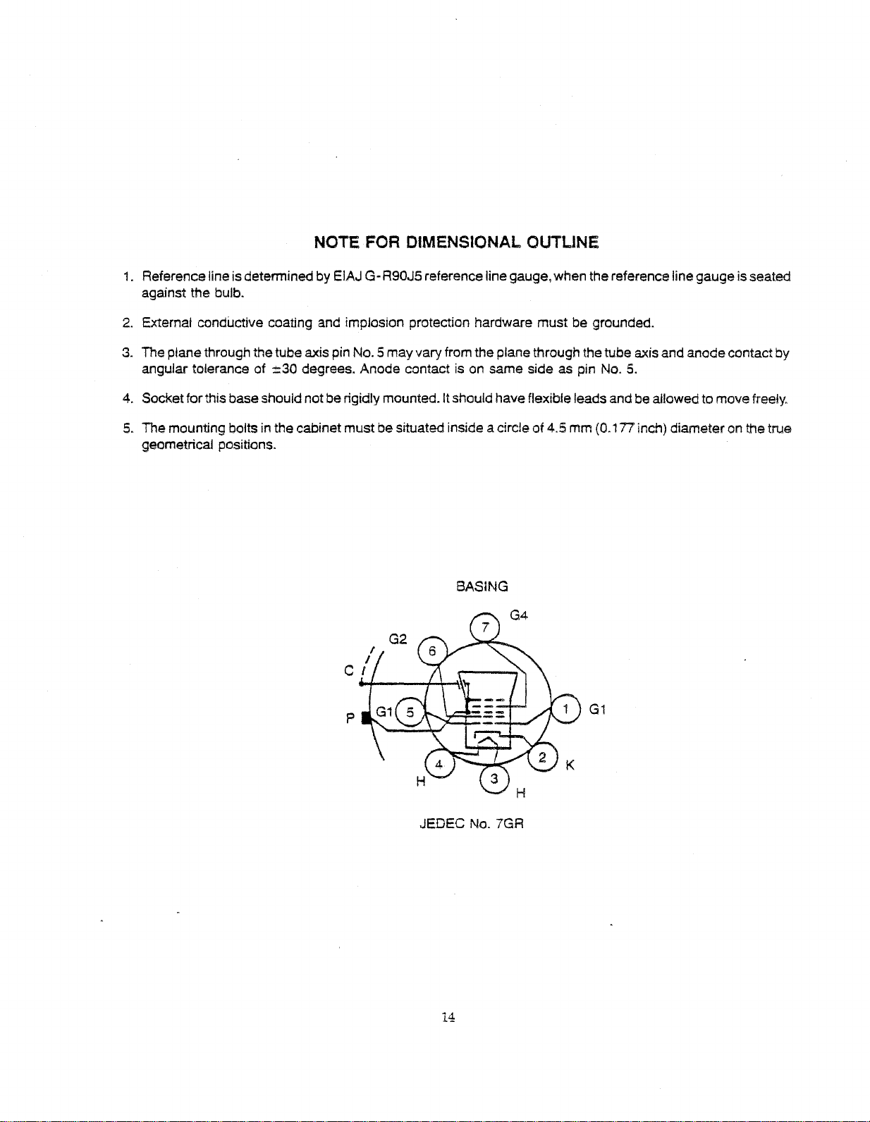
NOTE FOR DIMENSIONAL. OUTLINE
1.
Referencelineis determined by EIAJG-R90J5referenceline gauge, when the reference linegaugeis seated
against the bulb.
2.
External conductive coating and implosion protection hardware must be grounded.
3.
The planethrough the tube axis pin NO.5 may varyfrom theplane through thetube axis and anodecontact by
angular tolerance of
4. Socketforthis baseshould notbe rigidly mounted. Itshould have flexible leads and beallowed to movefreely.
:::30 degrees. Anode contact is on same side as pin NO.5.
5. The mounting boltsin the cabinet mustbe situated inside a circle
geometrical positions.
BASING
JEDEC No. 7GR
of
4.5 mm (0.1 n inch) diameter on the true
G1
14
Page 54

Page 55
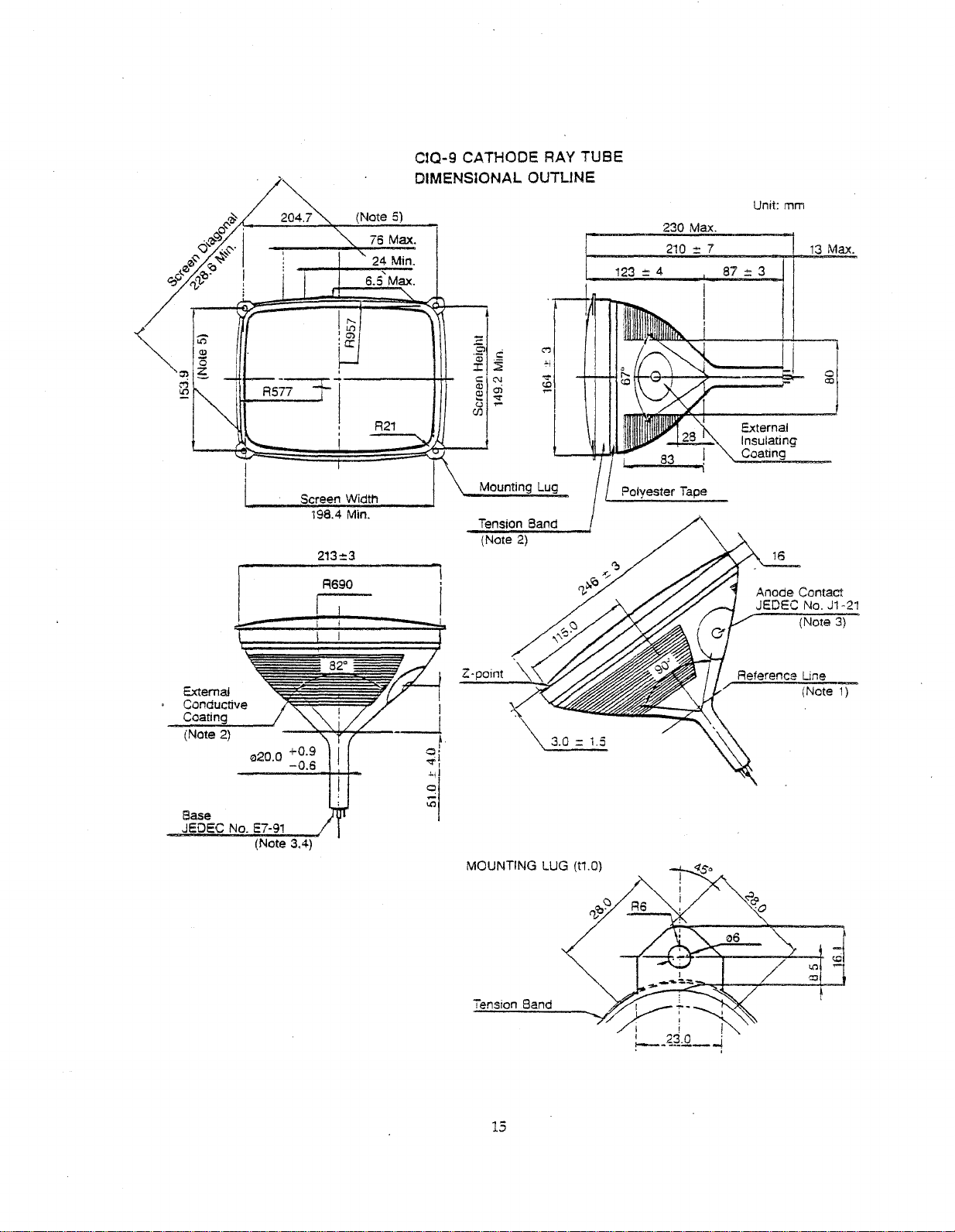
~~_-=;:::.:.:....-~--,(,;,.;N...;;.ot,;..e_5":')_1
.
fb>c:l
I'
Q"
.
5::-'
5::-
~
e,&~:1}J"?
!
R577
76 Max.
24 Min.
6.5'Max.
,
------t++-
ClQ-9 CATHODE RAY TUBE
DIMENSIONAL OUTLINE
~i
230
210
123
=:
4 87=:3
Max.
=7
Unit:
mm
J
External
Insulating
Coating
13
Max.
i
o
00
---.;:-:----::---
Sase
JEDEC
No. E7-91
(Note 3.4)
Screen Width
198.4 Min.
213=3
R~90
I !
i
---,~~
__
I
--l
of
""\
~I
Mounting Lug
Tension Band
(Note 2)
Z-point
MOUNTING
LUG (t1.0)
Polyester Tape
Anode
Contact
JEDEC
Reference Line
No. J1·21
(Note
(Note
3)
1)
Tension Band
15
Page 56

Page 57
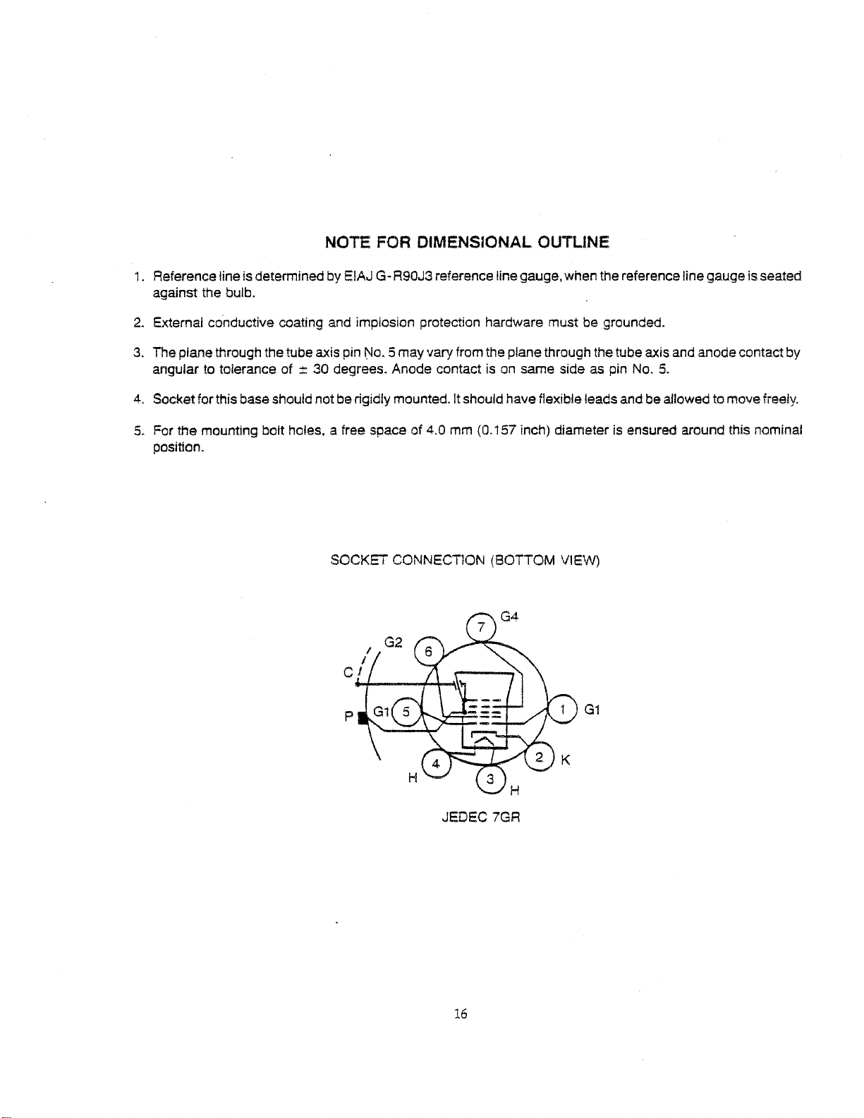
NOTE FOR DIMENSIONAL OUTLINE
1.
Reference line is determinedby EIAJ G-R90J3 reference line gauge, when the reference linegauge is seated
against the bulb.
2.
External conductive coating and implosion protection hardware must be grounded.
3.
The plane through the tube axis pin
angUlar to tolerance of
4.
Socketfor thisbase should not be rigidly mounted. It should have fleXible leads and beallowedtomovefreely.
5.
For the mounting bolt holes, a free space of 4.0 mm (0.157 inch) diameterisensured around this nominal
position.
:t
30 degrees. Anode contactison
No.5
may varyfrom the plane through the tube axis and anode contact by
same sideaspin
SOCKET CONNECT10N (BOTTOM VIEW)
No.5.
JEDEC 7GR
16
G1
Page 58

Page 59
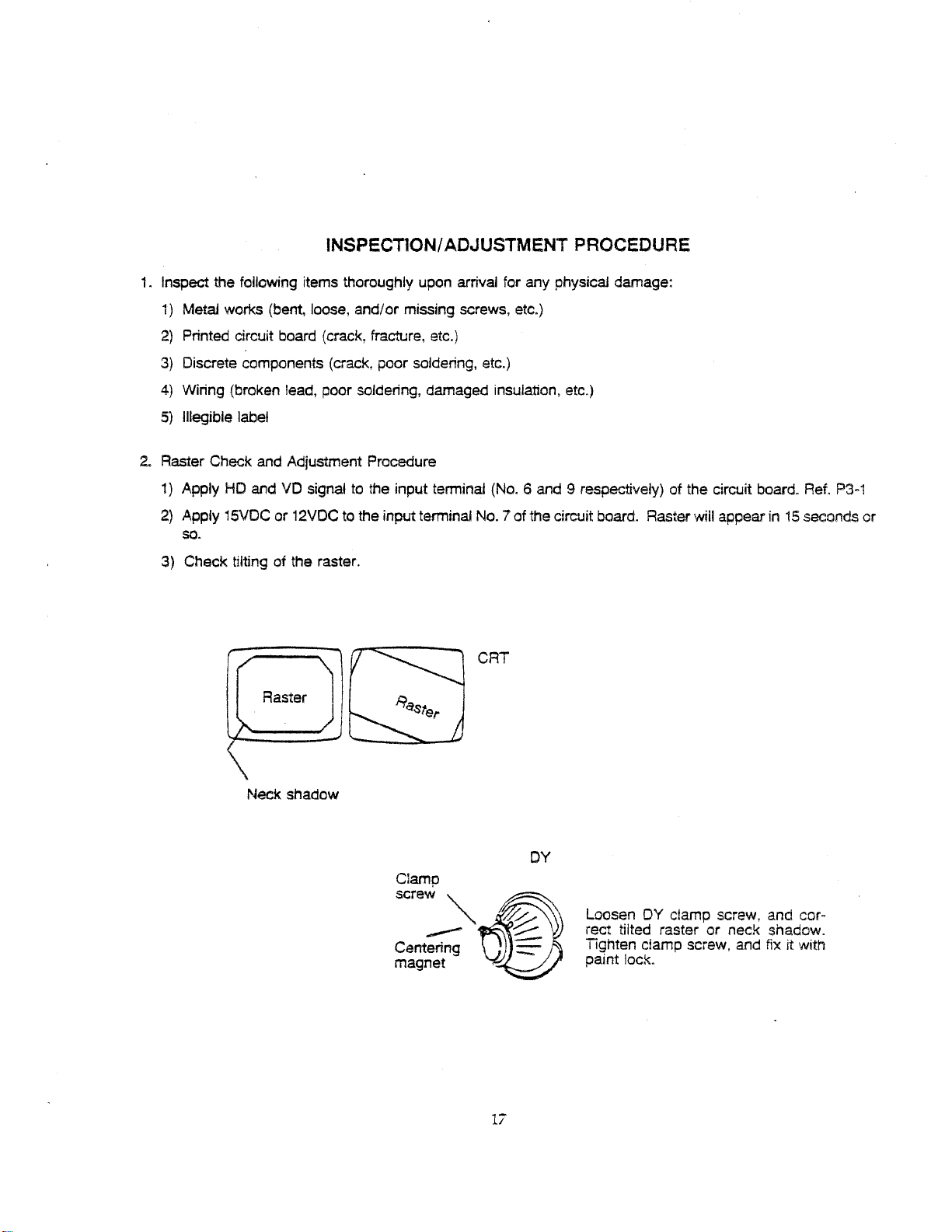
INSPECTION/ADJUSTMENT PROCEDURE
1.
Inspect the following items thoroughly upon arrival for any physical damage:
1)
Metal works (bent, loose, and/or missing screws, etc.)
2)
Printed circuit board (crack, fracture, etc.)
3) Discrete components (crack, poor soldering, etc.)
4)
Wiring (broken lead, poor soldering, damaged insulation, etc.)
5)
lIIegible label
2.
Raster Check and Adjustment Procedure
1)
Apply
HO
and
VO
signal to the input terminal
2)
Apply 15VOCor12VDC to the input terminal NO.7 of the circuit board. Raster will appear
so.
3) Check tilting of the raster.
(No.6
CRT
and 9 respectively) of the circuit board. Ref.
P3-1
in15seconds or
Neck shadow
Clamp
screw
---
Centering
magnet
"'~
'"
~
17
::.--
:::
DY
Loosen DY clamp screw, and cor·
rect tilted raster or neck shadow.
Tighten clamp screw, and
paint
lock.
fix it with
Page 60

Page 61
3.
Internal Controls and Adjustments
Display
Display Horizontal
Horizontal
Vertical Hold-VR101
Vertical Height-VR102
Vertical
Focus4VR105
SUb-brightness
(SEE PC BOARD PARTS LAYOUT FOR LOCATION)
Width4L102
Centering~l101
Unearity~L103
Unearity4
1)
The brightness can be controlled by adjusting VR104. If EXT-BRT is utilized, set ittothe center before
Internal Brightness Control is adjusted.
4
VR1
VR1
03
04
2) Blurred display may not be caused by improper focus adjustment High video signal
blurred
4.
Shock Test
Uft
one side of the unit about 2 inches off the surface and release. Observe whether or not the display is
affected by the shock; if the unit is affected, check for loose soldering, screws, etc.
5.
CRT Spot Test
Oneminute afterthepoweris turned off,ifthe spotappears atthe centerof the
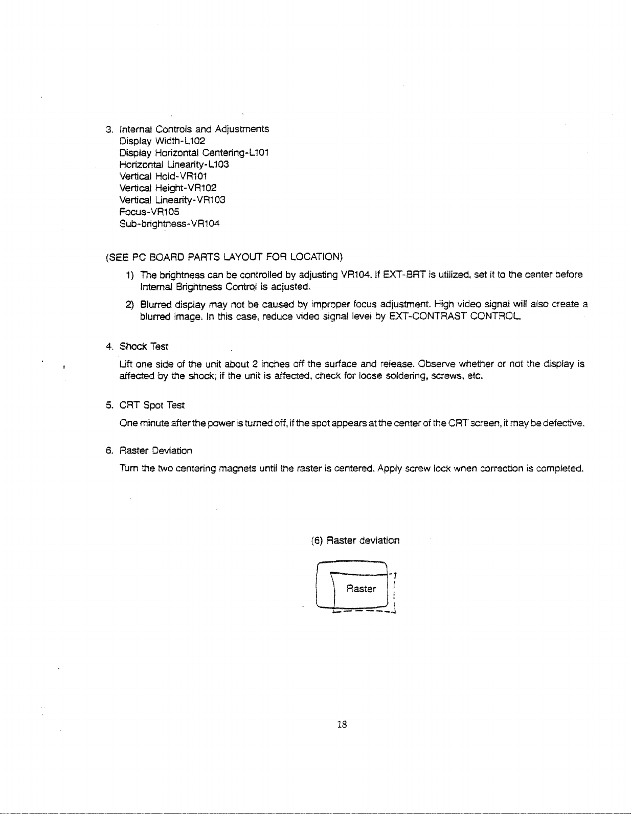
6.
Raster Deviation
Tum the two centering magnets until the raster is centered. Apply screw lack when correction is completed.
image.Inthis case, reduce video signal level by EXT4CONTRAST
CRT
(6) Raster deviation
CONTROL
screen,it may be defective.
will also create a
rr===1-1
u:::J[
....
-----~
18
Page 62

Page 63
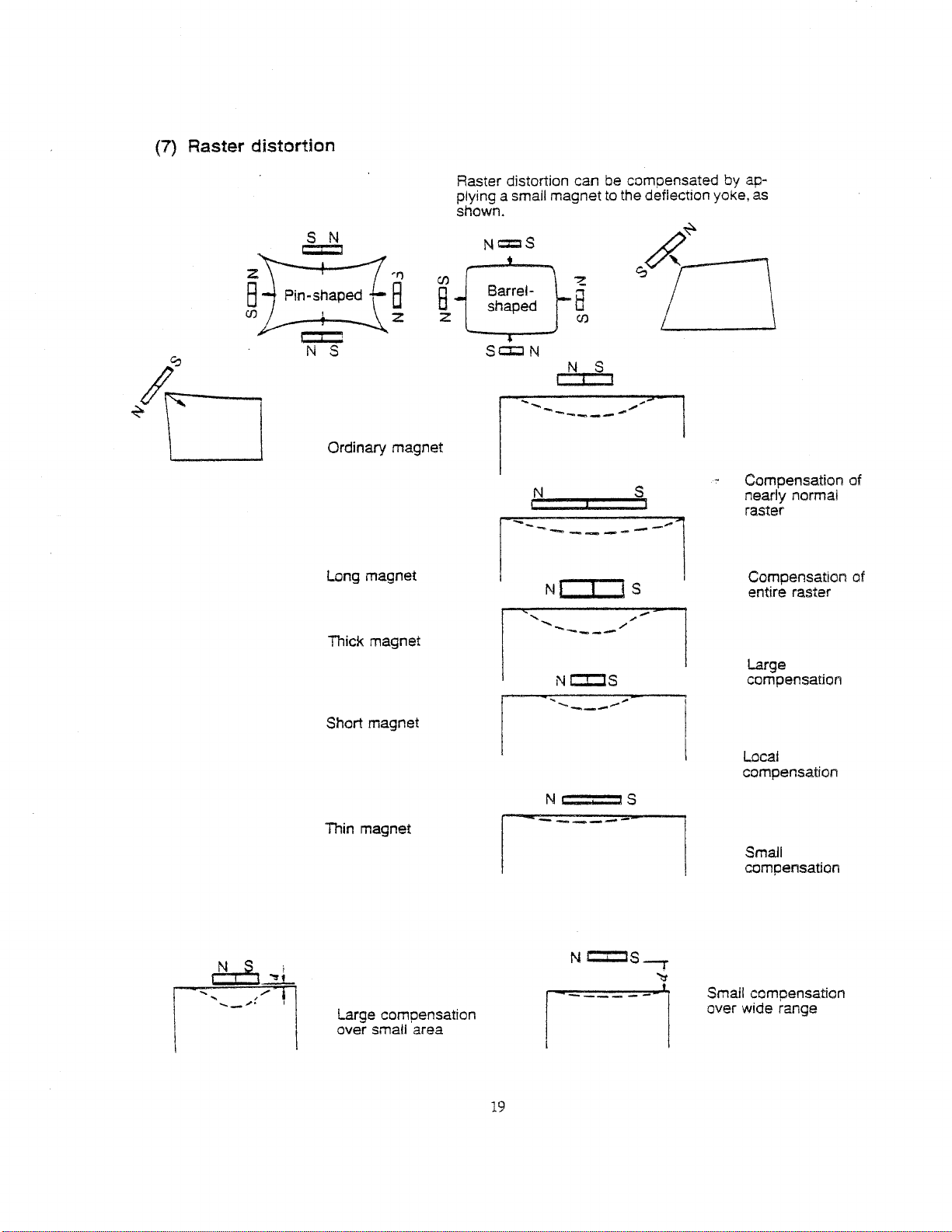
(7) Raster distortion
-I")
B
z
Ordinary magnet
Raster distortion can be compensatedbyapplying a small magnettothe deflection yoke,
shown.
N
c::I
S
C/)
8
z
Barrelshaped
S
c::r::J
-
N
.....
--
~
8
C/)
N
S
I
-----
~b
.....
-'"
as
Long magnet
Thick magnet
Short magnet
Thin magnet
Compensation of
nearly normal
raster
Compensation
entire raster
Large
compensation
Local
compensation
SmaH
compensation
of
/
is
_
.........
S
i
----l
> I
N
j
--......-.-_.-
---
1
NCI:JS
<-..,-....
.......
_---
I
N
c::::I:JS
, ...
......,.---"..",.
Ni
cc
1
Large compensation
over small area
Small compensation
over wide range
19
Page 64

Page 65
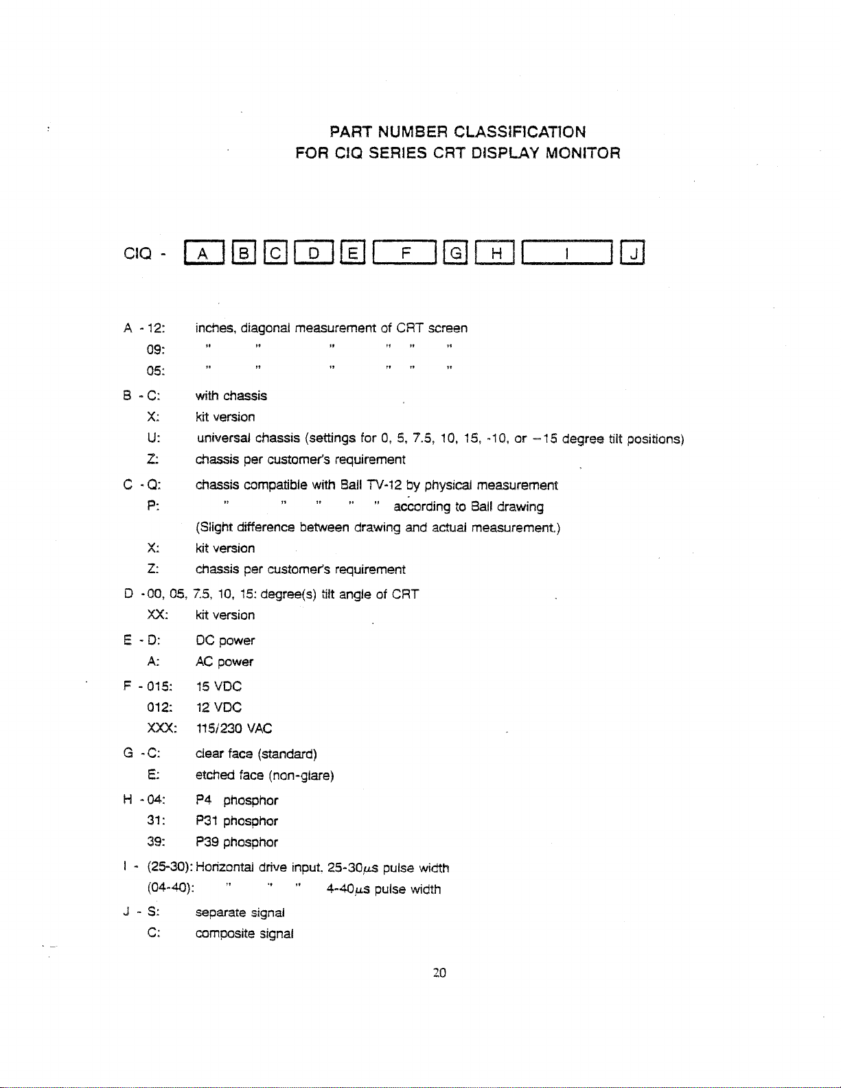
PART NUMBER CLASSIF1CATiON
FOR
cia SERIES CRT DISPLAY MONITOR
- W
CIQ
A
-12:
09:
05:
B -
C:
X:
U:
z:
C
.Q:
P:
X:
z:
D •00, 05,
XX:
E •
D:
A:
[§]
@]
[Q]
inches, diagonal measurement of CRT screen
with chassis
kit version
universal chassis (settings for
chassis per customer's requirement
chassis compatible with Ball TV-12 by physical measurement
(Slight difference between drawing and actual measurement.)
kit version
chassis per customer's requirement
7.5,
10, 15:
kit version
DC
AC
power
degree(s) tilt angle of CRT
power
fI]
,
0,5,7.5,
" according to
F
1@][Ii]
10, 15, ·10,or-15
l_~_l
Ball drawing
degree
Q]
tilt
positions)
F - 015:
012:
XXX:
G -
C:
E:
H • 04: P4 phosphor
31:
39: P39 phosphor
- (25-30): Horizontal drive
I
(04-40): 4-40,u.5 pulse width
J - S:
C:
15
VDC
12VDC
115/230
ciear face (standard)
etched face (non-glare)
P31
separate signal
composite signal
VAC
phosphor
input
25-30,uS
pUlse
width
20
Page 66

Page 67

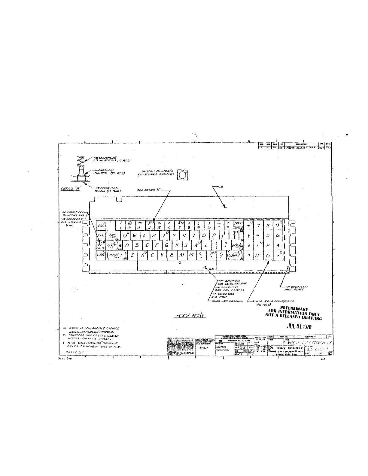
Jr
l'
If,~II n
Jl
11
16
!J
J.
1J
U
1111t
IL---------Alw
Hf-f
...
I"-F-F-IIJI.f'''+'+·_IJ'I\!2\'L1i'L
HH-t-t+++-J'L--"'I,
I'q~'f!1ftll&l-l&liLl---ji1-I-fl4l'
1~d!f-"l"'I-M3
u.
-1':~·.I'J'I!.J.--I!!-.ja.Ill--lI,'
......
L.J.
!J
:
g'11''------I
~
~
9
::l
, .
~J
'-
~
"
I
E~
,
13
-
7
"
"
6
-'
;;
'f.:
3-5
Page 68

Page 69
.15.
A:
ye.L;
ii//JUs.-;.
FLQ/)i/V.l:.';,
i/',71It.S::J
t.
19.-·,,~y
Tr.t:.
1110T,,5
i-a
/$.
I..CJI.j
r~CJFU.E
uT;':fR~E
.:ITft't!,J~/.Ji;":-
'~7,l'
C,3r¥J.q
I'l~,-
U:UTE-:.:
_Otk'HJ,L /VL
..
jf4!.-1lr
AJ.9,e.c:LO.
,~~4-·J!<k:,q.
.....
","J£'H£.:.ilt.'::
,::n:~
:
~T":-'H'::.o
tl.---L.l;7Z.LJ
Dr.-
A.:~'.
JUt31197B
Page 70

Page 71
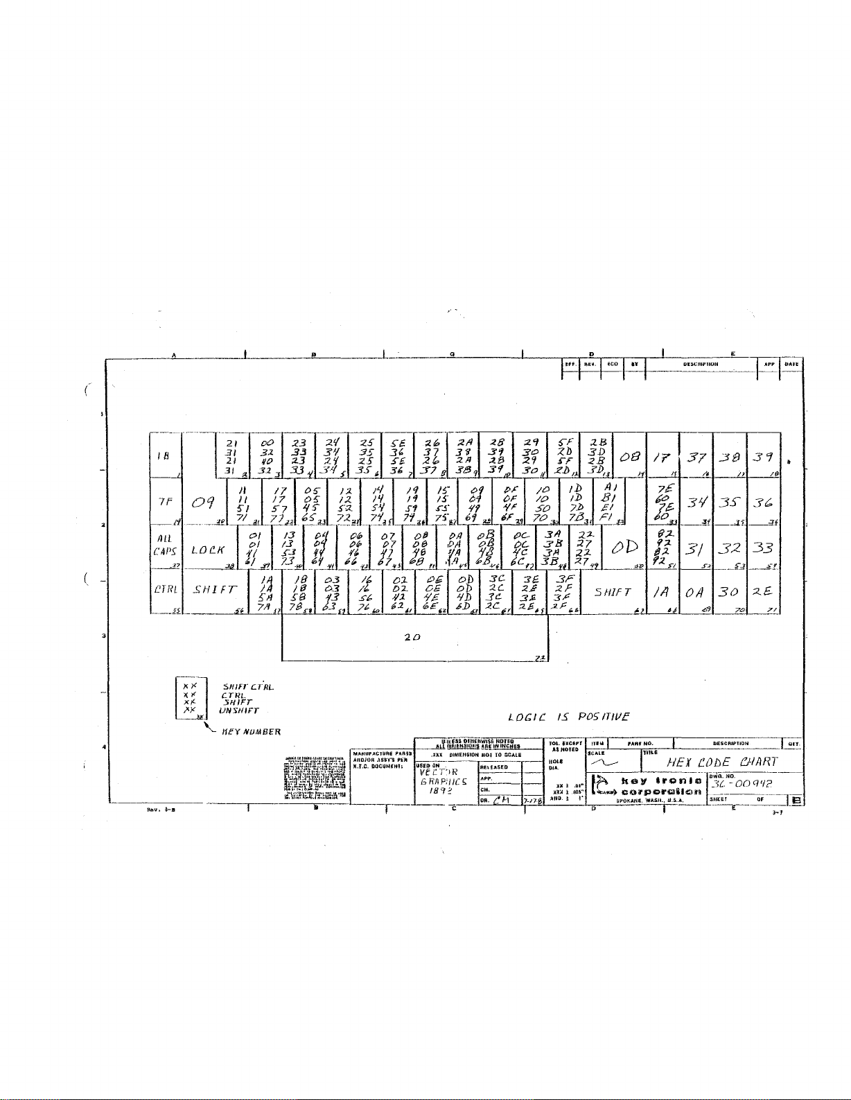
A
..
o D
~t-
._,,
E
__
cn_"_TlO_N_~_~~~
(
I B
[K1
I?
37
3£1
3'1
/11
011
30
2£
2D
SllIFr
l:.7:IIL
l:.TRL
5111FT
UN
SHIFT
'-
lIey
NUMBl'R
~:\il;~1i.J1,::ie:1.L"m
,~
111
.-
MAtjufACrliftE PARIS
AIIDJOR
.\55"f5
M.l.C.
tlOCUMflfl;
Plo:J,
-1---------!U
.JlU
usn
(IN
VEi'T'IR
GfiAP;J/C,
IB'I~
U;"II
..EUOIH£llWI$e
mtllENSIOll1
tllktHlilON
L
HDJED
!!!f
I"
INCHES
NOJTO:;CALE
DC;
IC.15
P051TWc
Page 72

 Loading...