

Page 1
Universal controller TCI-W13, TCI-W23
Universal controller TCI-W13, TCI-W23
Universal controller TCI-W13, TCI-W23
Doc: 70-00-0381A V1.0 20160523 © Vector Controls GmbH, Switzerland Subject to alterations
TCI-W13, TCI-W23 wall mounted universal controller
General description
The TCI-W is a stand-alone wall mounted electronic universal controller with two autonomous control loops.
Each control loop may use up to 2 PID sequences and 6 binary sequences. The TCI-W13 features
1 independent control loop, 1 universal input, 1 binary relay output and 2analog outputs, the TCI-W23 offers
2 independent control loops, 1 universal input, 1 passive input, 1 binary relay output and 2 analog outputs. A
detailed configuration is possible by following a simple setup routine. The TCI can be configured using the
standard operation terminal. No special tool or software is required.
Ordering, name convention
TCI-W23-U Optional functions and housing
│ │││ └───── Housing U = 2 x 4” type housing, blank = square housing
│ ││└─────── In-/outputs: 1 = 1UI, 1DOR, 2AO, 2 = 1UI, 1Passive In, 1DOR, 2AO
│ │└──────── Control loops: 1 = 1 control loop, 2 = 2 control loops
│ └───────── Mounting: W = Wall mounted
└──────────── Series Indication TCI
Item Name
Item Code
Loop
Int.
Temperature
Int.
Humidity
UI
TI
DO
Relays
AO
Option
TCI-W11
40-10 0073 1 1 0 1 0 2 1 Standard
TCI-W11-H
40-10 0162 1 1 1 1 0 2 1 RH Sensor 3%
TCI-W22
40-10 0075 2 1 0 2 0 2 1 Schedules
TCI-W22-H
40-10 0077 2 1 1 2 0 2 1 RH Sensor 3%
TCI-W13
40-10 0170 1 1 0 1 0 1 2 Standard
TCI-W13-H
40-10 0171 1 1 1 1 0 1 2 RH Sensor 3%
TCI-W23
40-10 0172 2 1 0 1 1 1 2 Schedules
TCI-W23-H
40-10 0173 2 1 1 1 1 1 2 RH Sensor 3%
Accessories
AES1-HT-A2
40-50 0067 1
RH Sensor 2%
AES1-HT-A3
40-50 0068 1
RH Sensor 3%
AES1-HT-A5
40-50 0069 1
RH Sensor 5%
Selection of actuators and sensors
Temperature sensors: Use only our approved NTC sensors to achieve maximum accuracy. Recommended
is SDB-Tn10 as duct sensor, SRA-Tn10 as room sensor.
Modulating actuators: Choose actuators with an input signal type of 0...10 VDC or 4...20 mA. Minimum and
maximum signal limitations may be set in software.
Binary auxiliary devices: E.g. pumps, fans, on/off valves, humidifiers, etc. Do not directly connect devices
that exceed the maximum limits as described under technical data. Observe startup current on inductive
loads.
Jumper configuration
Jumpers are mounted vertically only.
1. AO - Selection of output signal type:
o Left position: voltage output (0…10 V), factory default
o Right position: current output (0…20 mA)
2. AI - Selection of input signal type:
o Left position: voltage input (0…10 V), factory default
o Middle position: current input (0…20 mA)
o Right position: RT or dry-contact input
Mounting location
Install the controller on an easy accessible interior wall, approx. 1.5 m above the floor in an area of
average temperature.
Avoid direct sunlight or other heat sources, e.g. the area above radiators and heat emitting equipment.
Avoid locations behind doors, outside walls and below or above air discharge grills and diffusers.
Location of mounting is less critical if external temperature sensors are used.
Installation
1. Connect the wires to be connected to the terminals of the power case according to wiring diagram
2. Install the mounting plate to the flush mounting box. Make sure that the nipple with the front holding
screw is facing to the ground. Make sure the mounting screw heads do not stand out more than
5 mm (0.2”) off the surface of the mounting plate.
3. Ensure that the jumpers are set correctly.
4. Slide the two latches located on the top of the front part into the hooks at the upper side of the
mounting plate.
5. Carefully lower the front part until the interconnector reaches the mounting-plate. Continue
pressing in a gentle way until the front part is fully connected. While inserting the connectors, a
slight resistance can be felt. This is normal. Do not use excessive force!
6. With a Philips-type screw driver of size #2, carefully tighten the front holding screw to secure the
front part to the mounting plate. This screw is located on the front lower side of the unit. There is no
need to tighten the screw too much.
Technical specification
Warning! This device is intended to be used for comfort applications. Where a device failure endangers human life
and/or property, it is the responsibility of the owner, designer and installer to add additional safety devices to prevent
or detect a system failure caused by such a device failure. The manufacturer of this device cannot be held liable for
any damage caused by such a failure.
Failure to follow specifications and local regulations may endanger life, cause equipment damage and void warranty.
Power supply
Operating voltage
24 VAC 50/60 Hz ± 10%
Power consumption
Max 3 VA
Electrical connection
Terminal connectors,
wire 0.34…2.5 mm2 (AWG 22…13)
Clock backup
24 hours (Deluxe version only)
Signal inputs
Analog inputs
Input signal
Resolution
Impedance
UI1, UI2
DC 0...10V or 0…20mA
39 mV or 0.078 mA
Voltage: 98kΩ current: 240Ω
Temperature inputs
Range
Resolution
Accuracy
RT internal, external (Sxx-Tn10 sensor)
Int. NTC: 0…50 °C (32…122 °F)
Ext. NTC: -40…140 °C (-40…284 °F)
0.1 K
-40…0 °C (-40…32 °F): 0.5 K
0…50 °C (32…122 °F): 0.2 K
50…100 °C (122…212 °F): 0.5 K
> 100 °C (> 212 °F): 1 K
Humidity sensor AES-HT-Ax:
Range
Measuring accuracy
Hysteresis
Repeatability
Stability
Capacity sensor
0…100% RH
See figure below
1%
0.1%
< 0.5% / year
Signal outputs
Analog outputs
Output signal
Resolution
Maximum load
AO1
DC 0...10V or 0…20mA
39 mV, 0.078 mA
Voltage: ≥ 5kΩ current: ≤ 250Ω
Relays outputs
Type of disconnection
AC voltage
DC voltage
Micro-interruption
0…48 VAC, 2(1.2)A max. Observe local regulations
0…30 VDC, 2A max.
Insulation strength
between relays contacts and system
electronics:
2000VAC to EN 60730-1
Environment
Operation
Climatic conditions
Temperature
Humidity
To IEC 721-3-3
class 3K5
0…50 °C (32…122 °F)
<95% RH non-condensing
Transport & storage
Climatic conditions
Temperature
Humidity
Mechanical conditions
To IEC 721-3-2 and IEC 721-3-1
class 3K3 and class 1K3
-25…70 °C (-13…158 °F)
<95% RH non-condensing
class 2M2
Standards
conform according to
EMC standard
EMEI standard 73/23/EEC
EN 61000-6-1/ EN 6 000-6-3
Product standards
Automatic electrical controls for
household and similar use
special requirement on temperature
dependent controls
EN 60730-1
EN 60730-2-9
Degree of protection
IP30 to EN 60529
Pollution class
II (EN 60 730-1)
Safety class
II (IEC 60536) if voltage on DO > 48V
III (IEC 60536) if voltage on DO < 48V
Overvoltage category
I (EN 60730-1)
Housing
Materials: Cover, back part
Mounting plate
Fire proof ABS plastic (UL94 class V-0)
Galvanized Steel
General
Dimensions (H x W x D)
Front part: 88 x 88 x 21 mm (3.5” x 3.5” x 0.8”)
Power case: ø 58 x 32 mm (ø 2.3” x 1.3”)
Weight (including package)
TCI-W13 = 253g (8.9 oz)
TCI-W23 = 262g (9.3 oz)
Power failure
Upon power-interruption, all parameters and setpoints
are memorized in non-volatile memory, and therefore
do not have to be re-entered.
Error messages
Err1: An assigned input is not enabled or
missing. All control loops, functions and
outputs tied to this input will be disabled.
Verify input connections, jumper
settings and parameter settings for the
input involved.
Err3: A function refers to a disabled input.
Disable the function or enable the input.
Err4: Internal failure. Product must be replaced.
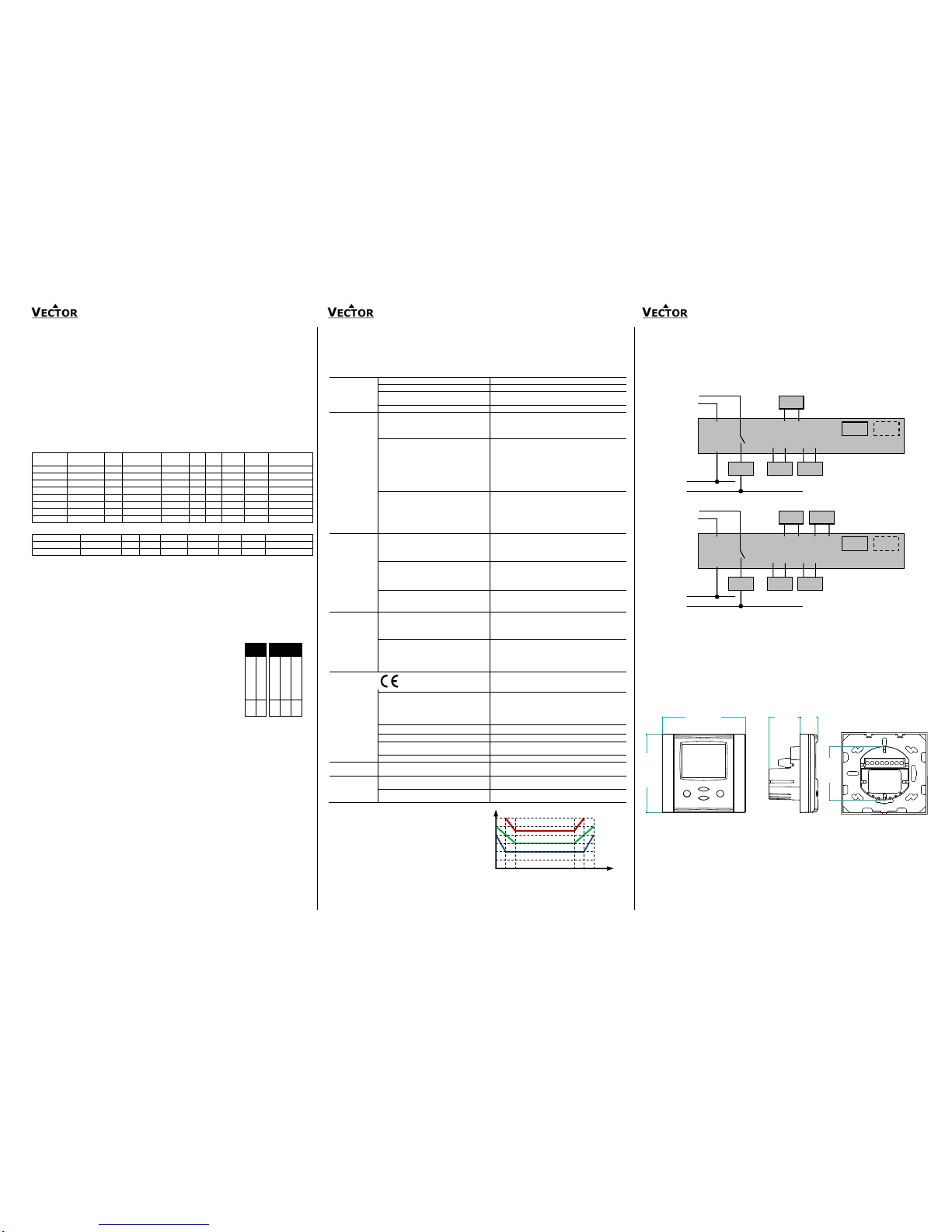
Wiring diagram
Warning: Live electrical components!
During installation, testing, servicing and troubleshooting of Vector Controls products, it may be necessary to
work with live electrical components. Have a qualified licensed electrician or other individual who has been
properly trained in handling live electrical components perform these tasks. Failure to follow all electrical
safety precautions when exposed to live electrical components could result in death or serious injury.
Description
G0 Power supply: 0V, -24VDC; common for power supply, analog in- and outputs
G Power supply: 24VAC, +24VDC
XU1 Universal input: NTC 10kΩ @ 25°C (77°F) or open contact,
0…10VDC or 0…20 mA (selectable by jumper)
XT2 Passive input: NTC 10kΩ @ 25°C (77°F) or open contact
YB1 Binary output: Potential free relays contacts (see technical specification)
YM1, XM2 Analog outputs: 0…10 V or 0…20 mA (selectable by jumper)
XT1 Internal temperature input
XH1 Internal humidity input if AES-HT is inserted
Dimensions mm (inch)
AO UI
0…10V
0…20mA 0…10V
0…20mA
RT or contact
█
█
X
H1 XT1
0V (COM)
24V AC/DC
2
G
TCI-W13
1
G0
0…48VAC, 0…30VDC
3
Q13
1 5
G0 Y1
YM1
1 7
G0 X1
X
U1
YB1
4
Q14
0V AC
1 6
G0 Y2
YM2
1 8
G0 X2
X
H1
X
T1
0V (COM)
24V AC/DC
2
G
TCI-W23
1
G0
0…48 VAC, 0…30VDC
3
Q13
1 5
G0 Y1
YM1
1 7
G0 X1
X
U1
YB1
4
Q14
0V AC
X
T2
1 6
G0 Y2
YM2
Distance for mounting screws:
Horizontal and vertical: 45 to 63 [mm]
88 (3.5)
32 (1.2)
21
(0.8)
88 (3.5)
58
(2.3)
Space required in flush mounting box:
ø 58 x 32 [mm] (ø 2.3” x 1.3”)
Figure 1: Max RH-tolerance at 25°C (77°F) per
sensor type
Relative humidity accuracy
%RH
%RH
10
20
30
40
100
90 0 50
60
70
80
±1
±0
±2
±3
±4
±5
AES-HT-A2
AES-HT-A3
AES-HT-A5
Page 2
Universal controller TCI-W13, TCI-W23
Universal controller TCI-W13, TCI-W23
Universal controller TCI-W13, TCI-W23
Doc: 70-00-0381A V1.0 20160523 © Vector Controls GmbH, Switzerland Subject to alterations
Controller configuration
Proceed in the following steps in order to adapt the controller to its application:
1. Set jumpers for inputs and outputs
2. Connect power supply and inputs
3. Program input parameters
4. Program control parameters
5. Program output parameters
6. Test function of unit
7. Switch off power
8. Connect outputs
9. Test control loop
10. Set user settings
Configuration parameters for firmware version 1.0
The TCI-Wx3 can be adapted to wide variety of applications. The adaptation is done with parameters. The
parameters can be changed on the unit without the need of additional equipment.
Identifying the firmware version
The parameters and functionality of controller depend on its firmware revision. It is therefore important to use
a matching product version and parameter set. The firmware version is marked on the package box of your
product. In order to identify the firmware version of an installed controller, press UP and DOWN keys
simultaneously for three seconds: The display will indicate the firmware version in the upper large digits and
the revision in the lower small digits. Press the LEFT key to return to normal operation.
Changing the parameters
1. Press UP and DOWN button simultaneously for three seconds. The display will indicate the
firmware version in the upper large digits and the revision in the lower small digits. Press the
RIGHT or POWER key to start login
2. CODE is shown in small display.
3. The code for accessing the user parameters is 0009, for control parameters it is 0241
4. Select this using UP or DOWN buttons.
5. Press the RIGHT or POWER button after selecting the correct code.
6. Once logged in the parameter group can be selected with the UP and DOWN key. Enter the
group with the RIGHT or POWER key.
7. Once the group is selected, the parameter is displayed immediately
8. Select the parameters with the UP/DOWN buttons. Change a parameter by pressing the
RIGHT button. Arrows 8 to 10 show up and indicate that the parameter may be modified
now. Use UP or DOWN buttons to adjust the value.
9. After you are done, press RIGHT or POWER in order to save the new value of the
parameter and return to the selection level. Pressing LEFT key will discard the value and
return to the selection menu without saving.
10. Press the LEFT key again so as to leave the parameter menu and return to the group
selection. Press LEFT key again while in the group selection to return to normal operation.
11. The unit will return to normal operation if no key is pressed for more than 5 minutes.
User parameters (password 09)
Parameter
Description
Range
Default
UP 00
Enable access to operation modes
ON, OFF
ON
UP 01
Enable access to set points
ON, OFF
ON
UP 02
Enable manual control in cascade or fan control mode
ON, OFF
ON
UP 03
Enable change of heating/cooling mode for 2 pipe systems
ON, OFF
ON
UP 04
Enable access to time programs:
ON, OFF
ON
UP 05
State after power failure:
0= off, 1= on, 2= state before power failure
0, 1, 2
2
UP 06
Enable economy (unoccupied) mode.
Shift the set point to a lower temperature in winter or higher
temperature in summer in order to save energy. Economy mode
may be activated through the POWER button, or with the external
input (typically for key card switches in hotel rooms or motion
detectors for meeting rooms.)
ON, OFF
ON
UP 07
Celsius or Fahrenheit: ON= Fahrenheit, OFF= Celsius
ON, OFF
OFF (Celsius)
UP 08
Show standard display while no key is pressed
ON, OFF
ON
UP 09
Select contents of large LCD display in standard mode:
0…5
1
00 = OFF
01 = Input
02 = Set point
03 = Analog output
04 = Binary output
05 = Clock
UP 10
Select ID of contents of upper digit display
0…4
1
Input:
1= 1T
2=1H
3= 1U
4= 2T
Set point:
1= Lp1
2= Lp2
Analog or
floating output:
1 = AO1
2 = AO2
Binary output:
1 = DO1
UP 11
Select contents of lower digit display in standard mode
0…5
TCI-W13 = 2
TCI-W23 = 5
UP 12
Select ID of contents of lower digit display
0…4
1
UP 13
Select analog output for display in vertical bar
00 = OFF
01 = AO1
02 = AO2
03 = Output lp1
04 = Output lp2
0…4
3
UP 14
Display heating/cooling state in standard display mode
ON, OFF
OFF
UP 15
ON = Alarms blink after being active and need to be confirmed
OFF= Alarms are only shown when they are active
ON, OFF
ON
UP 16
(TCI-W23)
Clock display type: OFF = 24-hr, ON = 12-hr(AM/PM)
ON, OFF
OFF
UP 17
(TCI-W23)
Reset timer for manual override of time schedule:
0= Not active
1...255= delay in minutes in case the controller is manually
switched on in scheduled off or economy mode. The controller will
return to scheduled function after expiration of this delay.
0…255
60 (min)
Page 3

Universal controller TCI-W13, TCI-W23
Universal controller TCI-W13, TCI-W23
Universal controller TCI-W13, TCI-W23
Doc: 70-00-0381A V1.0 20160523 © Vector Controls GmbH, Switzerland Subject to alterations
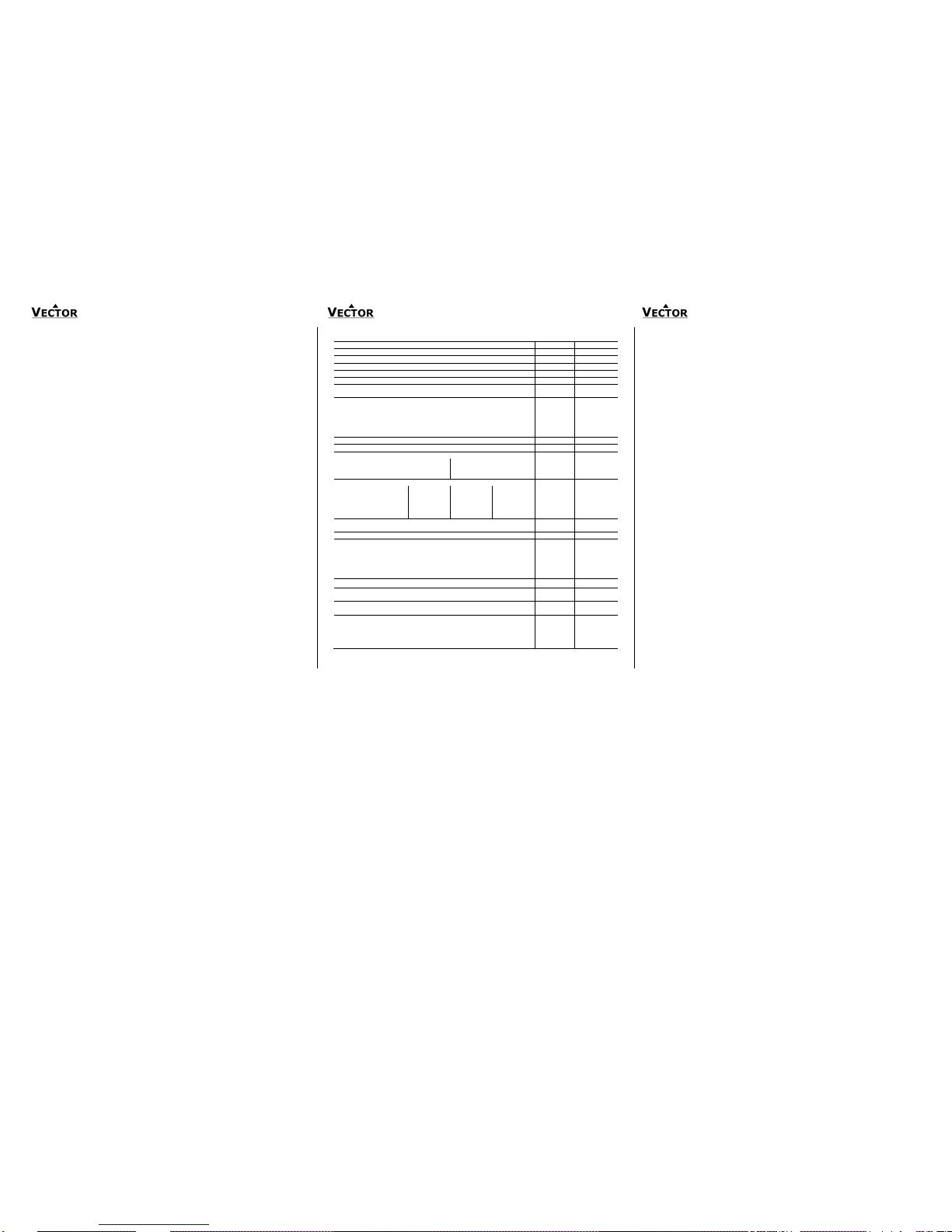
Control parameters (password 241)
Warning! Only experts should change these settings! The parameters are grouped according to
control modules. After completing the logging in, a control module must be selected before
accessing the parameters.
Module
Description
UI
Input configuration: 1T, 1H, 1U, 2T
LP
Control loops Lp1, Lp2
AO
Analog output configuration, AO1, AO2
DO
Binary output configuration, do1
FU
Special functions
Internal input configuration (TI1)
Parameter
Description
Range
Standard
1t 00
Enable internal sensor
ON, OFF
ON
1t 01
Display minimum value
-50…205
0
1t 02
Display maximum value
-50…205
100
1t 03
Sensor sampling rate(control speed decrease as rate
increases)
0…100
10
1t 04
Sensor calibration
-10.0…10.0 0 1t 05
Alarm 1 low limit
OFF, ON
OFF
1t 06
Alarm 1 low limit value
-50…205 °C
5°C (41°F)
1t 07
Alarm 2high limit
OFF, ON
OFF
1t 08
Alarm 2 high limit value
-50…205 °C
50°C (122°F)
1t 09
Hysteresis alarm 1, 2
0…100 °C
5°C (10°F)
1t 10
Calculate a range of inputs (0= not active):
1= average, 2= minimum, 3= maximum
0...3
0
Internal input configuration (HI1)
Parameter
Description
Range
Standard
1H00
Enable internal sensor
ON, OFF
OFF
1H01
Display minimum value
-50…205 0 1H02
Display maximum value
-50…205
100
1H03
Sensor sampling rate(control speed decrease as rate
increases)
0…100
10
1H04
Sensor calibration
-10.0…10.0
0
1H05
Alarm 3 low limit
OFF, ON
OFF
1H06
Alarm 3 low limit values
0…100%
5%
1H07
Alarm 4high limit
OFF, ON
OFF
1H08
Alarm 4 high limit values
0…100%
95%
1H09
Hysteresis alarm 3, 4
0…100%
5%
1H10
Calculate a range of inputs (0= not active):
1= average, 2= minimum, 3= maximum
0...3
0
External input configuration (UI1, TI2)
Parameter
Description
Range
Standard
1u 00
2t 00
Signal type (0= not active):
1= 0...10V or 0...20mA or open contact, 2= 2...10 V or
4…20 mA, 3= NTC temperature sensor
0...3
0
1u 01
2t 01
Display minimum value
-50…205
0
1u 02
2t 02
Display maximum value
-50…205
100
1u 03
2t 03
Analog input display range:
0= x0.1, 1= x1, 2= x10, 3 = x100
0...2
1
1u 04
2t 04
Analog input unit of measure:
0= no unit, 1= %, 2= °C /°F, 3= Pa
0...3
2
1u 05
2t 05
Sensor sampling rate
(control speed decrease as rate increases)
0…100
10
1u 06
2t 06
Sensor calibration
Range dep
0
1u 07
2t 07
Alarm 5 low limit (1u), alarm 7 low limit (2t)
OFF, ON
OFF
1u 08
2t 08
Alarm 5 low limit value (1u), alarm 7 low limit value (2t)
-50…205 °C
5°C (41°F)
1u 09
2t 09
Alarm 6 high limit (1u), alarm 8 high limit (2t)
OFF, ON
OFF
1u 10
2t 10
Alarm 6 high limit value 1u), alarm 8 high limit value (2t)
-50…205 °C
50°C (122°F)
1u 11
2t 11
Hysteresis alarm 5 and 6 (1u), alarms 7 and 8 (2t)
0…100 °C
5°C (10°F)
1u 12
2t 12
Calculate a range of inputs (0=not active):
1= average, 2= minimum, 3= maximum, 4= differential
0...4
0
LP: Control parameters (1L, 2L)
Parameter
Description
Range
Standard
1L 00
Select loop control input (0= loop disabled):
1= 1T, 2= 1H, 3= 1U, 4= 2T
0...4
1
1L 01
Minimum set point limit heating
per input
10 °C (50 °F)
1L 02
Maximum set point limit heating
per input
28 °C (82 °F)
1L 03
Minimum set point limit cooling
per input
18 °C (64 °F)
1L 04
Maximum set point limit cooling
per input
34 °C (93 °F)
1L 05
Enable set point compensation (0= disabled)
1= winter compensation, 2= summer compensation, 3= winter
and summer
0...3
0
1L 06
Loop input special (0= normal):
1= combine loop 1 and loop 2
2= cascade with reverse sequence of primary loop
3= cascade with direct sequence primary loop
4= cascade with both reverse and direct sequence of
primary loop
0...4
0
1L 07
Economy mode set point shift: (Function depends on 1L25)
The comfort (occupied) set point is shifted by the value set with
parameter. Reduces the heating set point and increases the
cooling set point.
per input
5 °C (10 °F)
1L 08
Dead zone between heating and cooling set points
The dead zone span lies between the heating and the cooling set
point. The output is off while the measured value is within the
dead zone span. A negative dead zone is not possible.
per input
1 °C (2 °F)
1L 09
Offset for heating PI sequence
per input 0 1L 10
Offset for cooling PI sequence
per input
0
1L 11
P-band heating
per input
2 °C (4 °F)
1L 12
P-band cooling
per input
2 °C (4 °F)
1L 13
Integral gain heating (0.1 steps)
low= slow reaction, high= fast reaction
0...25.5
0.0
1L 14
Integral gain cooling (0.1 steps)
0...25.5
0.0
1L 15
Measuring interval integral (seconds)
low= fast reaction, high value= slow reaction
0...255
1
1L 16
Action of stages:
0= cumulative: stage 1 stays on when 2 on comes on
1= single: stage 1 turns off when 2 on comes on
2= digital: stage 1 only, stage 2 only, then stage 1 plus 2
0...2
0
1L 17
Offset for heating/reverse binary sequences
per input
0.0 °C (0.0 °F)
1L 18
Offset for cooling/direct binary sequences
per input
0.0°C (0.0 °F)
1L 19
Switching span heating
per input
1.0 °C (2.0 °F)
1L 20
Switching span cooling
per input
1.0 °C (2.0 °F)
1L 21
Switching hysteresis
per input
0.5 °C (1.0 °F)
1L 22
Switching delay
0...255s
10s
1L 23
Activation of reverse/direct (heat/cool) sequence
OFF= activates based on demand
ON = follows heat/cool state of controller
ON/OFF
OFF
1L 24
Delay for heat /cool changeover when L23=OFF
0...255 min
5 min
1L 25
Fixed set point in standby mode
OFF = Standby set point shift applies
ON = In standby mode use minimum set point limit as set point in
heating mode or maximum set point limit in cooling mode
ON, OFF
OFF
1L 26
Set point compensation range, the maximum range the set point
is shifted.
0 = Temperature setback: the set point is shifted towards set point
limit
Acc input
0.0 °C
Analog output (1A, 2A)
Parameter
Description
Range
Standard
1A 00
Select control loop or special function (0= OFF):
1= LP1,
2= LP2
3= Dehumidify (4 pipe, max LP1 cooling, LP2 direct)
4= Manual positioning or time schedule controlled
(0…100%)
5= Transmit value of an input
0...5
1
1A 01
When 1A00=1 configure output:
0= Heating/reverse
1= Cooling/direct
2= Heating and cooling (2 pipe)
3= Transmit set point
When 1A00 = 4 manual positioning or time schedule controlled
0 = time schedule controlled only
1 = manual positioning and time schedule controlled
When 1A00=5, select input (0= function disabled):
1= 1T, 2= 1H, 3= 1U, 4= 2T
0...4
0
1A 02
Type of output signal: OFF= 0...10V, 0...20mA,
ON= 2...10V, 4...20mA
ON, OFF
OFF
(0...10V,
0…20 mA)
1A 03
Minimum limitation of output signal default and in loop heating
mode
0...100 %
0
1A 04
Maximum limitation of output signal default and in loop heating
mode
0...100 %
100%
1A 05
Minimum limitation of output signal in loop cooling mode
0...100%
0%
1A 06
Maximum limitation of output signal in loop cooling mode
0...100 %
100%
1A 07
Choose alarm to set output to 100% (output 0% on conflicting
alarms)
Alarm: 1 2 3 4 5 6 7 8
Selection
1A 08
Choose alarm to set output to 0%. (output 0% on conflicting
alarms)
Alarm: 1 2 3 4 5 6 7 8
Selection
1A 09
Transmit value (1A00=5): minimum input value
Acc input - 1A 10
Transmit value (1A00=5): maximum input value
Acc input
-
Page 4

Universal controller TCI-W13, TCI-W23
Universal controller TCI-W13, TCI-W23
Universal controller TCI-W13, TCI-W23
Doc: 70-00-0381A V1.0 20160523 © Vector Controls GmbH, Switzerland Subject to alterations
Binary output – binary control
Parameter
Description
Range
Standard
1d 00
Enable digital or PWM output
OFF= 1d is a digital output
ON = 1d is a PWM output
ON, OFF
OFF
1d 01
Select control loop or special function (0= OFF)
1= LP1
2= LP2
3= Dehumidify (4 pipe, max LP1 cooling, LP2 direct)
4= Manual positioning (on/off)
5= State functions
0…5
0
1d 02
When 1d01=1, configure output:
0= Stage 1 heating/reverse
1= Stage 1 cooling/direct
2= Stage 1 heating and cooling, reverse and direct
3= Stage 2 heating/reverse
4= Stage 2 cooling/direct
5= Stage 2 heating and cooling, reverse and direct
If 1d01 = 4 Manual positioning or time schedule controlled
0 = Time schedule controlled only
1 = Manual positioning and time schedule controlled
When 1d01=5, select state functions:
0= ON if controller operation state is ON
1= ON while demand on any output
2= ON while controller in heating mode and
operation state ON
3= ON while controller in cooling mode and operation state ON
0…5
0
1d 03
Switch-off delay (time output active with no more demand)
Delay is in seconds or minutes depending on d09
0...255s
90s
1d 04
Switch-on delay (time demand active before output on)
In state mode 1d01=5 outputs disabled during switch-on delay
Delay is in seconds or minutes depending on d09
0...255s
5s
1d 05
Activate PWM, set cycle time, seconds (>0 activates, 0 deactivates)
0...1275
0
1d 06
Choose alarm to set output to ON (output OFF on conflicting alarms)
Alarm: 1 2 3 4 5 6 7 8
Selection
1d 07
Choose alarm to set output to OFF (output OFF on conflicting
alarms)
Alarm: 1 2 3 4 5 6 7 8
Selection
1d 08
Display fan symbol while active
ON, OFF
OFF
1d 09
Binary switching delays in minutes or seconds
OFF = delays are in seconds, ON = delays are in minutes
ON, OFF
OFF
Special functions – SP compensation
Parameter
Description
Range
Standard
Fu 00
Select compensation input (0= function disabled):
1= 1T, 2= 1H, 3= 1U, 4= 2T
0…4
0
Fu 01
Winter compensation set point setback
OFF= shift toward control loop heating set point minimum
ON= shift toward control loop heating set point maximum
ON, OFF
OFF
Fu 02
Winter compensation lower limit value – end shift
Range acc input
5°C
Fu 03
Winter compensation upper limit value – start shift
Range acc input
20°C
Fu 04
Summer compensation set point setback
OFF= shift toward control loop cooling set point minimum
ON= shift toward control loop cooling set point maximum
ON, OFF
ON
Fu 05
Summer compensation lower limit value – start shift
Range acc input
35°C
Fu 06
Summer compensation upper limit value – end shift
Range acc input
40°C
Fu 07
Show hot/cool symbol while compensation active
ON, OFF
OFF
Special functions – remote control comfort – economy
Fu 08
Select comfort/economy changeover input (0= disabled):
1= 1T, 2= 1H, 3= 1U, 4= 2T
0…4
0
Fu 09
Economy activation delay (seconds)
0...1275
300
Fu 10
Input limit 1
Range acc input
10
Fu 11
Input limit 2
Range acc input
90
Special functions – remote control enable – disable
Fu 12
Select enable–disable input (0=function disabled):
1= 1T, 2= 1H, 3= 1U, 4= 2T
0…4
0
FU 13
Manual override permitted (without waiting for delay).
This function allows starting the controller; although the
enable conditions are not met. The controller will switch off
again if the running conditions are not met until the disable
delay is expired.
ON, OFF
OFF
Fu 14
Enable delay (seconds)
0...1275
0
Fu 15
Disable delay (seconds)
0...1275
300
Fu 16
Range of limits:
OFF = When limit 2 is greater than limit 1, enable when
input value is greater than limit 2,disable when
input value is less than limit 1.
When limit 2 is less than limit 1, enable when input
value less than limit 1, disable when input value is
greater than limit 2.
ON = When limit 2 is greater than limit 1enable when
input value is between limit 1 and limit 2.
When limit 2 is less than limit 1, enable when input
value below limit 2 or above limit 1
ON, OFF
OFF
Fu 17
Input limit 1
Range acc input
10
Fu 18
Input limit 2
Range acc input
90
Fu 19
Disable in case of alarms
Selection
Special functions – remote heat / cool (reverse / direct) change
Fu 20
Select heat/cool changeover input (0=function disabled):
1= 1T, 2= 1H, 3= 1U, 4= 2T,
5= h/c status loop 1, 6= h/c status loop 2
0…6
0
Fu 21
Cooling activation delay (seconds)
0...1275
300
Fu 22
Input limit 1
Range acc input
20
Fu 23
Input limit 2
Range acc input
40
 Loading...