

Vector OPU-D42-W50 Operation Manual
Operation terminal OPU-D42-W50
Operation terminal OPU-D42-W50
Operation terminal OPU-D42-W50
Doc: 70-00-0326B-50, V2.0, 2013-01-07 © Vector Controls GmbH, Switzerland Subject to alteration
OPU-D42-W50 operation terminal for TLR-D42 base units
Features
Temperature control for 2-pipe and 4-pipe fan coil systems.
Automatic fan control for three stage fans.
Control for heating, cooling and fan only operation
Cost saving option with Economy functionality and set point limitation
For large rooms: Master – Slave option: One terminal may drive up to 8 base units in parallel.
Password protected programmable user and control parameters
External sensor or open contact for remote control, external heat – cool change or auto-changeover
on supply or outdoor temperature with selectable activation limits
One terminal may control up to 8 base units in parallel mode
Deluxe Version:
Clock and time schedule functions
Blue backlight for LCD
Infrared remote controller option:
With special features for Boost and delayed switching on or off
Ordering
A working controller consists of one operation terminal and at least one base unit.
Item name
Item code
Function
Type
Key-data
TLR-D42-24
40-11 0085
24VAC
Base unit
Fan coil controller with:
1 TI int or ext
3 DO (Relay) Fan control
2 AO (0-10VDC) PI control
1 DO HEAT/COOL
TLR-D42-230
40-11 0086
230VAC
OPU-D42
40-10 0166
Standard
Operation
terminal (2x4”)
OPU-D42-D
40-10 0167
Deluxe
Accessories
OPR-1
40-50 0001 2xAAA bat
Infrared remote controller
S-Tn10-2
SD-Tn10-12-2
SD-Tn10-20-2
SDB-Tn10-12
SDB-Tn10-20
SRA-Tn10
SOB-Tn10
40-20 0001
40-20 0002
40-20 0003
40-20 0051
40-20 0004
40-20 0005
40-20 0059
Flying lead sensor with 2 m cable
Flying lead duct sensor 12cm immersion depth, 2m cable
Flying lead duct sensor 20cm immersion depth, 2m cable
Duct sensor with housing, 12cm immersion depth
Duct sensor with housing, 20cm immersion depth
Room sensor
Outdoor sensor
Selection of actuators, fans and sensors
Temperature Sensors: Use only our approved NTC sensors to achieve maximum accuracy.
Modulating Actuators: Choose actuators with an input signal type of 0-10VDC. The current on the output is
limited to 10mA.
Fan motors: Observe power limits and startup currents. Note: startup currents may be a multiple of the rated
current of a fan. Verify with the fan supplier if unclear.
Installation Terminal
1. Install the mounting plate to the electrical connection box. Make sure that the nipple with the front
holding screw is facing to the ground. Make sure the screw heads do not stand out more than 5 mm
of the surface of the mounting plate.
2. Connect the wires of the terminals to the communication wires according wiring diagram
3. Slide the two latches located on the top of the front part into the hooks of the mounting plate.
4. Lower the front part until located flat on the wall and the mounting plate is not visible anymore. Make
sure the connection cable does not get into the way.
5. Tighten the front holding screw to secure the front part to the mounting plate.
Connection base to terminal
Max. Distance: 200m (565 ft.)
Normal twisted pair copper wires maybe used for wiring in an EMC-save en vironment. In an
impaired EMC environment use only shielded cables. The operating voltage must comply
with the requirements for safety extra-low voltage (SELV) as per EN 60 730.
1 terminal may drive up to 8 base units. See wiring for parallel connections . Total wire
distance should not exceed 200 m.
Conductor resistance will influence external temperature reading. 450 Ω will result in an
increase of 1°C (2°F). Compensate using UP-08 if external temperature is used to control
unit.
Technical Specification
Power Supply
Operating Voltage
5V DC ±10%
Power Consumption
30mA max Electrical Connection
Terminal Connectors
Deluxe type only:
Power backup for real time clock
Min 48h if charged for 24h
Signal Inputs
Temperature Inputs
Range
Accuracy
0…50 °C (32…122 °F)
0.5°C, 1°F
Communication
Base - Terminal
Communication Type
Cable Type
Max Distance
Digital: peer to peer
Use twisted pair copper wire 0.8…2.5 mm2
(AWG18…AWG13) 200m (650ft) use shielded wire
in an EMC challenged environment. Conductor
resistance must be compensated if external sensor
is used
Environment
Operation
Climatic Conditions
Temperature
Humidity
To IEC 721-3-3
class 3 K5
0…50 °C (32…122 °F)
<95 % r.H. non-condensing
Transport & Storage
Climatic Conditions
Temperature
Humidity
Mechanical Conditions
To IEC 721-3-2 and IEC 721-3-1
class 3 K3 and class 1 K3
-25…70 °C (-13…158 °F)
<95 % r.H. non-condensing
class 2M2
Standards
conformity
EMC Directive
Low Voltage Directive
2004/108/EC
2006/95/EC
Product standards Automatic electrical
controls for household and similar use
Special requirement on temperature
dependent controls
EN 60 730 –1
EN 60 730 – 2 – 9
Electromagnetic compatibility for
domestic sector
Emissions: EN 60 730-1
Immunity: EN 60 730-1
General Terminal
Safety Class
III (IEC 60536)
Degree of Protection
IP30 to EN 60 529
Material: Cover, back part
Mounting Plate
ABS plastic (UL94 class V-0)
Galvanized Steel
Color
White RAL 9003
Dimensions (H x W x D) : OPA :
OPU :
88 x 88 x 24 mm (3.5 x 3.5 x 0.9 in)
112 x 73 x 18 mm (4.4 x 2.9 x 0.8 in)
Weight including package:
OPA-D42, OPU-D42
OPA-D42-D, OPU-D42-D
180 g (6.3 oz)
190 g (6.7 oz)
Power Failure
All the parameters and set points are memorized and don’t need to be reentered. The clock will need to be reset.
Status LED
The status LED is located on the base unit between the two low power terminal connector groups. The status LED
may display the following feedback:
No light: No power or unit is damaged
Blink every 1s: Error, term inal – base unit do not match or signal is not clear.
Blink every 2s: Norm al communication, base unit detected
Blink every 5s: Base unit op erates normal, no terminal detected
Error messages
Err1: Error temperature sensor. The internal temperature sensor may be damaged or not present.
Err2: External input for heat / cool auto-change-over missing or damaged.
FP: Frost protection is active.
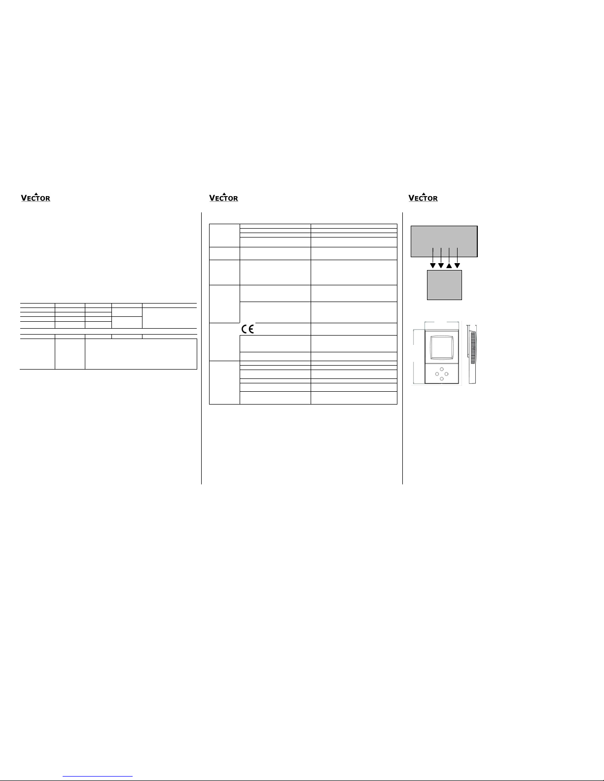
Wiring Diagram
Dimensions Terminal
73 (2.9)
15
(0.6)
112 (4.4)
OPU
3
(0.1)
TLR-D42 Base unit
1 2 3 4
OPU-D42(-D)
10
T1
11
T2
12
T3
13
T4
Operation terminal OPU-D42-W50
Operation terminal OPU-D42-W50
Operation terminal OPU-D42-W50
Doc: 70-00-0326B-50, V2.0, 2013-01-07 © Vector Controls GmbH, Switzerland Subject to alteration
Configuration parameters for firmware version 2.0 –W50
This controller can be adapted to wide variety of fan coil applications. The adaptation is done with
parameters. The parameters can be changed on the unit without the need of additional equipment.
Identifying the firmware version
The parameters and functionality of controller depend on its firmware revision. It is therefore important to use
a matching product version and parameter set. The firmware version is shown on the large LCD digits when
pressing UP and DOWN buttons for more than 3 seconds simultaneously.
Changing parameters
The parameters may only be accessed by entering a code. There are two levels of parameters: User
operation parameters for access control settings and Expert parameters for control functions and unit setup.
The codes for user levels and expert levels are different. Only control experts should be given the control
parameter code.
The parameters can be changed as follows:
1. Press UP and DOWN button simultaneously for three seconds. The display shows the
software version in the large digits and the software revision in the small digits.
2. Pressing the OPTION button will indicate CODE on the small digits and 000 on the large
digits.
3. The code for accessing the user parameters is 009
4. Select this using UP or DOWN buttons.
5. Press OPTION button after selecting the correct code.
6. Once logged in, the parameter is displayed immediately.
7. Select the parameters with the UP/DOWN buttons. Change a parameter by pressing the
OPTION button. The MIN and MAX symbols show up and indicate that the parameter may
be modified now. Use UP or DOWN buttons to adjust the value.
8. After you are done, press OPTION or POWER in order to return to the parameter selection
level.
9. Press the POWER button again so as to leave the menu. The unit will return to normal
operation if no button is pressed for more than 5 minutes.
User Parameters (Access Code: 009)
Parameter
Description
Range
Standard
UP 00
Enable change of operation modes,
ON, OFF
ON (Enabled)
UP 01
Enable change of set points
ON, OFF
ON (Enabled)
UP 02
Enable manual control fan speeds
ON, OFF
ON (Enabled)
UP 03
Enable manual change of Heating/Cooling Mode.
Applies only for 2-pipe or 4-pipe systems.
ON, OFF
ON (Enabled)
UP 04
Enable Access to time programs
ON, OFF
ON (Enabled)
UP 05
State after power failure: 0 = OFF, 1 = ON, 2 = Last State
0, 1, 2
2
UP 06
Enable Economy (unoccupied) Mode.
Shift the setpoint to a lower temperature in winter or higher
temperature in summer in order to save energy. May be activated
through the POWER button, or with the external input (typically
for key card switches in hotel rooms or motion detectors for
meeting rooms.)
ON, OFF
OFF
(no economy)
UP 07
Celsius or Fahrenheit, OFF for Celsius, ON for Fahrenheit
ON, OFF
OFF (Celsius)
UP 08
Calibrateinternal temperature sensor
–10° to +10° in 0.1° steps. (Sensor is factory calibrated, use this
feature for field adjustment only as required.)
-10…10
0
UP 09
Enable Frost Protection.
Activates the output independent of operation mode when the
control temperature drops below 5°C or 41°F. The controller
returns to normal operation when the temperature increases
above 10°C or 50°F.
ON, OFF
ON (Enabled)
UP 10
Select contents of Large LCD display in standard mode:
0…6 02
Temperature
00 = OFF
01 = Setpoint
02 = Temperature Sensor
03 = Output Fan Speed
04 = Clock
05 = Alternative Sensor
06 = Output in Percent
UP 11
Select contents of small LCD display in standard mode
0…6
Standard:
01 Setpoint
Deluxe:
04 Clock
00 = OFF
01 = Setpoint
02 = Temperature Sensor
03 = Output Fan Speed
04 = Clock
05 = Alternative Sensor
06 = Output in Percent
UP 12
Contents of vertical bar in standard mode
OFF = Fan Speed
ON = Control output
ON, OFF
ON (control)
UP 13
Clock display type: Only available for deluxe version
OFF = Show 24hour clock
ON = Show 12hour clock (AM, PM)
ON, OFF
OFF (24h)
UP 14
Reset timer for override mode: Only available for deluxe version
0 = Reset of override mode is not active.
1…255 = dela y in minutes to switch off device if ON/Economy
mode is activated while the unit is scheduled to be in
OFF mode
0…255
60 (Min)
Control Settings (Access Code: 241)
Warning! Only experts should change these settings!
Set point limits
Parameter
Description
Range
Standard
FC 00
Minimum setpoint limit in Heating mode
-40-60°C (160°F)
16°C (61°F)
FC 01
Maximum setpoint limit in Heating mode
-40-60°C (160°F)
24°C (75°F)
FC 02
Minimum setpoint limit in Cooling mode
-40-60°C (160°F)
18°C (64°F)
FC 03
Maximum setpoint limit in Cooling mode
-40-60°C (160°F)
30°C (86°F)
Fan control sequence
FC 04
Economy (unoccupied) Mode temperature shift:
The comfort (occupied) setpoint is shifted by the value
set with parameter. If heating is active the comfort
setpoint will be decreased, if cooling is active, the
setpoint will be increased. (Enable with UP06.)
0…10.0K (20°F)
4.0°C (8°F)
FC 05
Switching Span Heating,
if set to 0, only 1 fan speed will be used
0…10.0K (20°F)
0.0°C (0.0°F)
FC 06
Switching Span Cooling
if set to 0, only 1 fan speed will be used
0…10.0K (20°F)
0.0°C (0.0°F)
FC 07
Switching Hysteresis is the difference between
switching on and switching off. A small hysteresis will
increase the number of switching cycles and thus the
wear on fan and relays contacts.
0…10.0K (20°F)
0.5°C (1°F)
FC 08
Mold Protection:
In mold protection, the fan keeps running independent
of temperature as long as the unit is switched on.
ON, OFF
ON
FC 09
Delay OFF (Minimum running time)
0…255 s
10s
FC 10
Delay ON (Minimum stopping time)
0…255 s
10s
FC 11
Control option:
0 = Cooling only
1 = Heating only
2 = 2-pipe system
3 = 4-pipe system
0-4 3 FC 12
Dead Zone Span:
The Dead Zone Span lies between the heating and the
cooling setpoint. The output is off while the temperature
is within the dead zone span. A negative dead zone is
not possible.
0…100°C (200°F)
2.0°C (4°F)
FC 13
Heat/Cool Changeover Delay (if set to FC11 = 3):
A demand to switch between heating and cooling must
persist for the length of time set with this parameter
before the controller switches. Prevents activation of a
sequence during a short-term change in temperature in
order to protect equipment (with control overshoot for
example)
0…255 min
5 min
PID control sequence
FC 14
P – band heating XPH
0…10.0K (20°F)
2.0°C (4.0°F)
FC 15
P – band cooling XPC
0…10.0K (20°F)
2.0° (4.0°F)
FC 16
KIH, Integral gain heating, in 0.1 steps, 0 disables ID part
low value = slow reaction, high value = fast reaction
0…25.5
0.0
FC 17
KIC, Integral gain cooling, in 0.1 steps
0…25.5
0.0
Proportional control (P-band)
The proportional control function calculates the output based on the difference between setpoint and
measured value. The proportional band (P-band) defines the difference between setpoint and measured
value which will result in a 100% output. Setting the proportional band to 0 disables proportional control.
Integral gain KI
The integral gain defines how fast the output increases in case the setpoint is not met by the room
temperature. A low value indicates a slow reaction, a high value a fast one. If the value is chosen too high,
the controller will start to swing. Depending on the room size and heating / cooling equipment used a value
between 0.1 and 1.5 should be sufficient. Below are suggested values:
Heating: KIH: 0.1-0.5, Cooling: KIC: 0.3-0.8
Configuration of Analog outputs
Parameter
Description
Range
Standard
FC 18
Configuration of analog output signal
0 = 0-10V
1 = 2-10V
2 = Manual override (useful for commissioning)
When low fan speed: 25% output
When medium fan speed 50% output
When high fan speed 100% output
0-2
0 (0-10V)
FC 19
Function of analog outputs
0 = Disabled
1 = Control: Heating only (AO1 only)
2 = Control: Cooling only (AO2 only)
3 = Control: Heating and cooling (AO1 and AO2)
0…3
3
FC 20
Output of AO1 in cooling mode if FC19 = 1 or
Output of AO2 in heating mode if FC19 = 2
0…100%
0%
For heating only or cooling only option, the analog output may set to a fixed output while the b inary
sequence is active. This is used for VAV systems.
Configuration of binary output
Parameter
Description
Range
Standard
FC 21
Function of binary output
0 = Disabled
1 = Control: Heating only
2 = Control: Cooling only
3 = Control: Heating and cooling
4 = Enable: On if device is on
5 = Enable: On if device is on and in heating mode
6 = Enable: On if device is on and in cooling mode
7 = Frost protection alarm
0…7
1
FC 22
Level to activate binary output if in dual AO-DO mode:
Dual AO-DO mode = both analog and binary outputs
are assigned to same control sequence.
0…100%
65%
FC 23
Level do deactivate binary output if in dual AO-DO
mode
Dual AO-DO mode = both analog and binary outputs
are assigned to same control sequence.
0…100%
15%
The three fan outputs are assigned to the fan speed module. Only output 4 can be ass igned by this
parameter (FC21). Select if the binary output should work as controls output in heating or cooling only
or both for heating and cooling mode.
Dual AO-DO mode: if both the analog and the binary output is assigned as control outp ut to the same
sequence, the binary output will then switch on when the analog output reaches the value defined in
FC22 for example 95% and switch off when it drops below FC 23 for example 45%. Note: This output
does not follow min running and stopping delays. It only reacts to the conditions mentioned above. In
order to take advantage of this function we recommend using larger proportional bands.
Configuration of inputs
FC 24
External input:
0 = No external input
1 = External temperature sensor
2 = Occupation sensor – Comfort / Economy
3 = Occupation sensor – Comfort / Off
4 = Heat / Cool changeover
5 = Key card with alternative setpoint
6 = Key card with full reset
0…6
0
FC 25
Activation delay (Minutes) = the time the binary input
needs to be open before economy/off mode is activated.
0…255 min 5 FC 26
Auto-changeover limit heating FC24 = 4
or economy setpoint in heating mode if FC24 = 5
-40…60°C (160°F)
28°C (82°F)
FC 27
Auto-changeover limit cooling FC24 = 4
or economy setpoint in cooling mode if FC24 = 5
-40…60°C (160°F)
18°C (64°F)
FC 28
Comfort setpoint in heating mode if FC24 = 6
-40…60°C (160°F)
21°C (70°F)
FC 29
Comfort setpoint in cooling mode if FC24 = 6
-40…60°C (160°F)
24°C (75°F)
Configuring the function of the external input
FC24 = 1
External control
input
The external sensor is the control input.
FC24 = 2
Switching
Economy and
Comfort modes
Economy (unoccupied) and Comfort (occupied) modes are controlled
through an external contact by connecting the input through a dry contact
to signal common. This function may be used together with key card
switches for hotels or motion detectors for offices.
FC24 = 3
Switching Energy
Hold OFF and
Comfort modes
Opening the input will force the unit into the OFF operation mode. The
operation mode cannot be overridden by using the terminal. Connecting
the input to signal common returns control of the operation mode to the
terminal. This function may be used as window contact to prevent loss of
energy.
FC24 = 4
Heat – Cool
changeover
Switch heating and cooling mode based on supply media or outside
temperature or binary contact. See below for further details.
FC24 = 5
Key card with
alternative
setpoint
As with FC24 = 2, the key card function switches economy (unoccupied)
and comfort (occupied) modes. Instead of using the setpoint shift, the
setpoints in unoccupied mode are defined by parameter FC26 in heating
mode and FC27 in cooling mode.
Fan speed in unoccupied mode is limited to low speed.
Fan speed and setpoint will be remembered after re-inserting the key card.
FC24 = 6
Key card with full
reset
Similar as FC24 = 5 with the difference that setpoints, fan speed and
operation mode are reset each time the key card is inserted. This is helpful
for business hotels. Setpoints will be reset to FC28 or FC29.
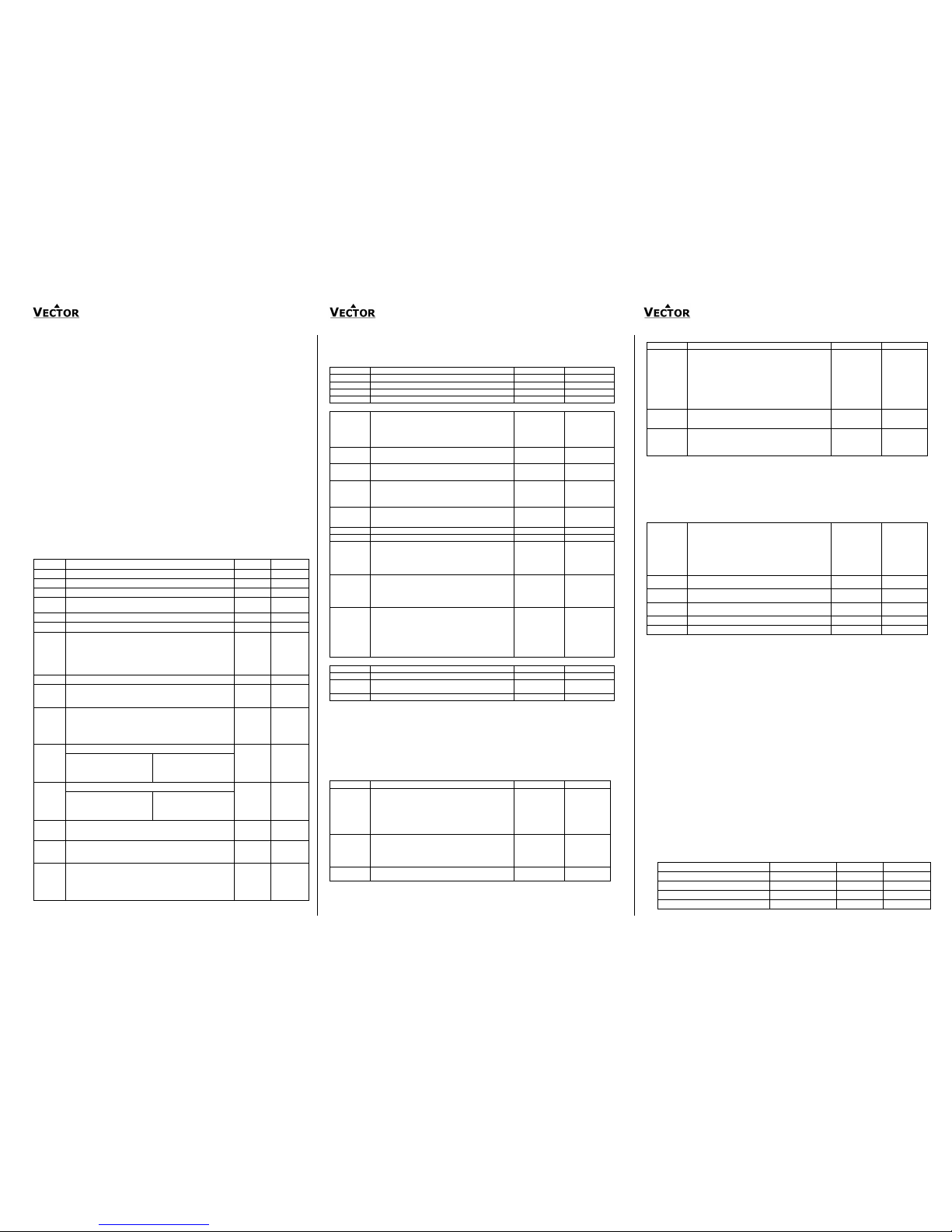
Configuring auto changeover input if FC24 = 4:
The auto changeover function automatically changes heating and cooling mode based on supply
media temperature or outdoor temperature. The difference between the two is in the values of the
changeover limits FC26 and FC27. See table below for recommended settings.
Heating and cooling may be as well changed by an open contact switched to signal ground. Note: all
signal ground levels of involved controllers must be the same in case more than one controller is
switched.
Recommended settings for FC26 and FC27:
Change over mode FC24=4
Relation FC26 to FC27
Example:FC26
Example:FC27
Supply media
FC26> FC27
28°C (82F)
18°C (64F)
Outside temperature
FC26< FC27
15°C (59F)
25°C (77F)
Dry contact: Heating if contact closed
FC26> FC27
25°C (77F)
15°C (59F)
Dry contact: Cooling if contact closed
FC26< FC27
15°C (59F)
25°C (77F)
 Loading...