

Page 1
X2-OPERATING MANUAL
Doc : 70-00-0736, Serie X2, 20190206 © Vector Controls GmbH, Schweiz Page 1
subjects to alteration www.vectorcontrols.com
VECTOR
Operating instructions for the
X2 operating system
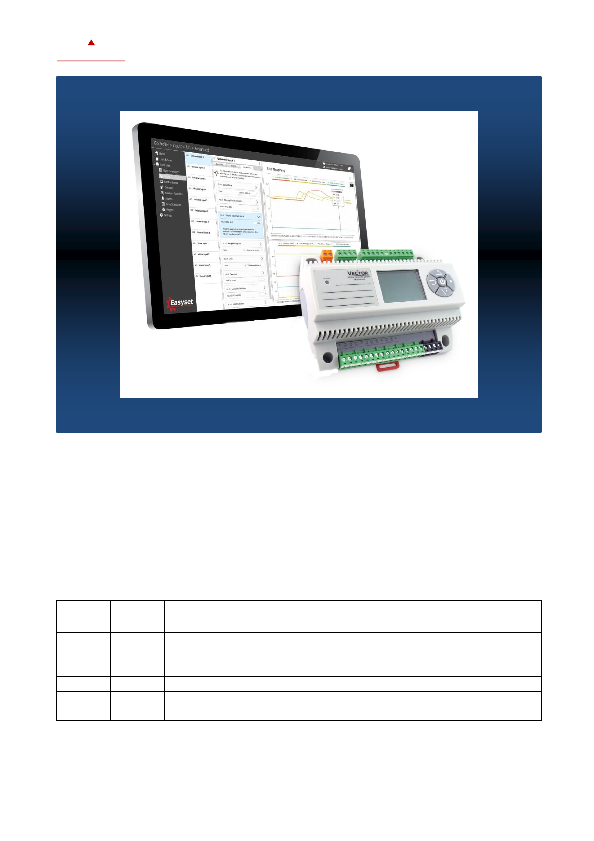
The X2 operating system was designed for universal controllers and sensors. Devices based on the X2
operating system contain a multitude of standardized functions and application possibilities. From simple
ventilation controllers for domestic applications to HVAC system solutions for entire buildings. There is a
suitable solution for almost every application. With the EasySet program, the controllers can be conveniently
read out, programmed and transferred to other controllers.
Applications
These operating instructions apply to devices of the X2 series with integrated control unit, as well as to devices of the
OPA2 and OPU2 series.
Ordering
Model
Items
Description
OPA2-VC
40-500007
Remote terminal
OPA2-2T-VC
40-500047
Remote terminal with T + 2 passive inputs
OPA2-2TH-VC
40-500023
Remote terminal with RHT + 2 passive inputs
OPU2-T-VC
40-500100
Remote terminal with T
OPU2-TH-VC
40-500101
Remote terminal with RHT
OPU2-2T-VC
40-500024
Remote terminal with RT + 2 passive inputs
OPU2-2TH-VC
40-500025
Remote terminal with RHT + 2 passive inputs
In addition, the various product descriptions and the programming instructions for technicians are contained in separate
documents. This should facilitate the work with the different controllers and operating levels.
Page 2
X2-OPERATING MANUAL
Doc : 70-00-0736, Serie X2, 20190206 © Vector Controls GmbH, Schweiz Page 2
subjects to alteration www.vectorcontrols.com
VECTOR
Display and Operation
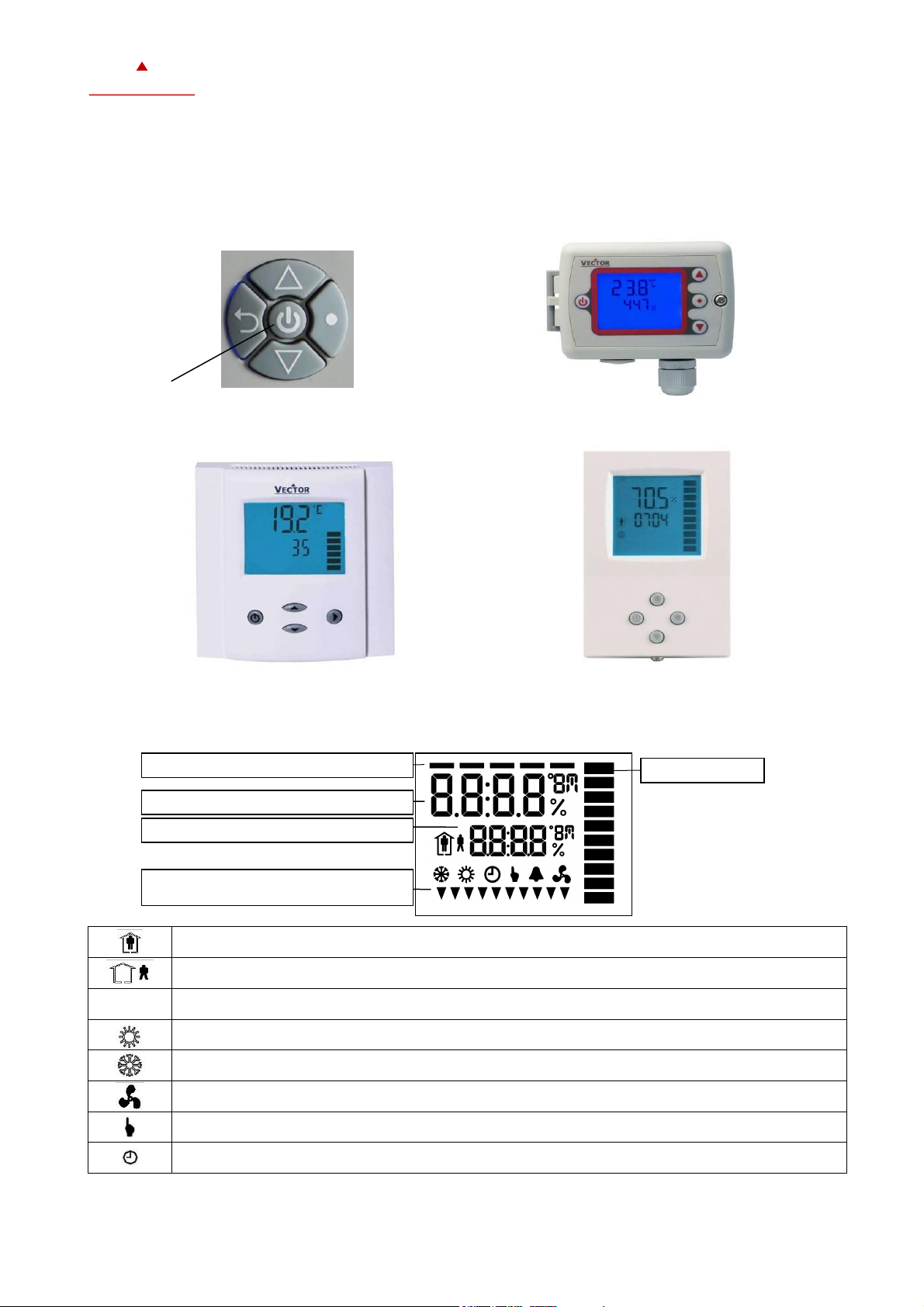
Key Layout
Display and Symbol
Occupied: (Comfort) All control functions operating per set points.
Unoccupied: (Standby, Economy) If enabled, alternative set points are used with the intention to reduce
energy consumption.
OFF
OFF: (Energy Hold Off, EHO) Normal control functions are inactive, inputs are monitored for alarms.
Heating (reverse) active
Cooling (direct) active
Fan active
Manual override, delay on enable function
Schedule set
Vertical Bar
Loop indication
Display of setpoint, clock or parameter number
Display of input or parameter value
Idle display: Active digital output and
Parameter setting
OPU
LEFT Button
UP Button
DOWN Button
RIGHT Button
UP Button
LEFT Button
DOWN Button
RIGHT Button
OPA
LEFT Button
TCX2/TCI2
UP Button
RIGHT Button
DOWN Button
ON/OFF Button
UP Button
RIGHT Button
DOWN Button
SDC2/SOC2
LEFT Button
Page 3

X2-OPERATING MANUAL
Doc : 70-00-0736, Serie X2, 20190206 © Vector Controls GmbH, Schweiz Page 3
subjects to alteration www.vectorcontrols.com
VECTOR
Idle Display
• The idle display is activated when no key has been pressed for 30 seconds.
• The idle display can be deactivated by the technician. Last active control loop or manual output will remain displayed.
Display of control loop
• Active when changing set points. Large digits show input value. Small digits show set point. Horizontal bars top left
show which loop is being displayed.
Override of secondary set point in cascade control
• With cascade control, manual override of the secondary circuit can be activated. This is defined by the technician in
the controller settings.
• If cascade control is active (with VAV for example) the user can override the primary loop and manually select the set
point of the secondary loop (the loop is then changed to constant air volume mode). This function is helpful for tuning
the VAV system. While the secondary loop is displayed change the set point with UP/DOWN. The hand symbol
appears. Change setpoint again to cancel cascade override. The hand symbol disappears.
Manual Mode
• The hand symbol is displayed during a pending delay. For example, if a start -up delay is active. The controller
remains switched off and displays the hand symbol until the delay has elapsed. Then the controller switches on and
the hand symbol goes out.
Status-LED
• A status LED is located on the upper left side of the controller housing. During normal operation the LED blinks
briefly once every 5 seconds. It will blink every second in case there is an alarm or fault condition.
Power Failure
• All parameters and set points are memorized and do not need to be re -entered. The switch-on behaviour on return
of the power supply is set by the technician.
• Clock and time schedule settings are retained for 48 hours after being powered for at least 10 hours.
Error Messages
Err1: Communication error
Err2: Internal error: Firmware version of the memory does not match firmware.
Err3: Timer error: Set time and acknowledge error. If an error occurs again at a previously set time, the watch is
faulty. Time switching functions are not guaranteed in this case.
Err4: Configuration error: An assigned input is not activated or has failed. Check all settings and ensure that all
inputs used are activated and functional.
Err5: Copy error: Communication error with external memory AEC-PM1 or AEC-PM2.
Err6: Copy error: Checksums of the data record are incorrect. The data record is invalid .
Page 4

X2-OPERATING MANUAL
Doc : 70-00-0736, Serie X2, 20190206 © Vector Controls GmbH, Schweiz Page 4
subjects to alteration www.vectorcontrols.com
VECTOR
Extended operating level
Clock operation
Note Accuracy
Warning: The TCX2-40863 and devices with a -C addition have a real-time clock. This clock is accurate to two seconds a
day. Other TCX2 series devices calculate the time based on the processor's internal clock speed. This time source is
accurate to approx. 2 minutes per day. If the controller uses its time program functions, it is therefore necessary to
synchronize the time of these controllers at least every 24 hours with an exact time base.
Time Programs
The controller contains a real time clock with battery back -up. Up to 12 schedules based on time and day of the week may
be programmed (Pr01 through Pr12). Schedules may change controller operation mode (on, off, occupied, unoccupied),
change fan state, position an output, or change a loop set point. A blinking clock indicates that the time has not been set
or the unit was without power for longer than 48 hours. The time needs to be set to allow time schedules to operate.
Summer / winter time changeover may be activated using user parameters.
1. Clock setup
1.1. Press RIGHT button longer than 2 sec.
➔SEL and Date or Time (alternately) is displayed.
1.2. Press RIGHT button briefly to change the time and date:
minutes flashes: UP/ DOWN button for adjustment, RIGHT key for storage
Hours flashes: UP/ DOWN button for adjustment, RIGHT key for storage
DAY1 flashes: UP/ DOWN button for adjustment, RIGHT key for saving the day of
the week
Day of the month flashes: UP/ DOWN button for adjustment, RIGHT key for
storage
Month flashes: UP/ DOWN button for adjustment, RIGHT key for storage
Year flashes: UP/ DOWN button for adjustment, RIGHT key for storage
1.3. Press LEFT button (1x) for back.
2. Enable/disable time schedules
2.1. Press RIGHT button longer than 2 sec.
➔SEL and Date or Time (alternately) is displayed.
See picture
1.1.
2.2. Press UP button
➔ PRO and SEL is displayed
2.3. Press RIGHT button:
Schedule status indicates whether it is OFF or ON
When status is ON = in the display. Press the RIGHT button to change the status.
2.4. Press LEFT button (1x) for back to the submenu.
ON
Pro
OFF
Pro
SEL
Pro
SEL
2006
SEL
day7
SEL
1230
Page 5

X2-OPERATING MANUAL
Doc : 70-00-0736, Serie X2, 20190206 © Vector Controls GmbH, Schweiz Page 5
subjects to alteration www.vectorcontrols.com
VECTOR
3. Create weekly time schedules
3.1. Press RIGHT button longer than 2 sec.
➔SEL and Date or Time (alternately) is displayed.
See picture
1.1.
3.2. Press UP button
➔PRO und SEL is displayed.
Set time program to ON or OFF with RIGHT button
Change to Pr 01 - Pr 12 with the UP or DOWN button.
3.3. Press RIGHT button to select the following:
no = switching time not activated
OP = Operating mode ON (normal operation), ECO (reduced operation) or OFF
(protective operation)
LP = setpoint of a control loop (setting range from 0-100%)
AO = Positioning of the analog output (output must be in manual mode!)
FAN = Fan control (fan stages from FSP0-3 and Auto)
do = positioning of the digital output (output must be in manual mode!)
Hday = Annual time schedule. (holidays)
A function can be selected by pressing the UP or DOWN button.
Press RIGHT key to complete the selection.
4. Select a switching time
4.1. Press RIGHT button longer than 2 sec.
➔SEL and Date or Time (alternately) is displayed.
4.2. Press UP button ➔ PRO und SEL is displayed.
4.3. Press RIGHT button while PRO-ON or OFF is displayed:
Press UP or DOWN button to select between programs (point 3.3.) 1 - 12.
See picture
1.1.
2.2.
2.3.
3.2.
4.4. Press the RIGHT button and select the desired program (e.g. Pr01),
Press the UP or DOWN button to scroll through the possible selections to see which function
(no/OP/LP... etc.) is to be assigned to e.g. Pr01.
In this case, the control loop (LP) on program 1 (Pr01) is selected.
(1.bar indicates that step 1 is complete).
Press the RIGHT button to set the desired time. This is done using the UP and DOWN buttons
from 00:00 - 23:45
(2. bars indicate that step 2 is complete).
Continue with RIGHT button.
5. Apply selected switching time (Annual schedule)
DAY1 and Pr01 are now displayed on the screen:
To execute the time program on Monday (Day1), press the UPPER button.
A triangle symbol appears on the 1
In order not to execute the time program on Monday, press the LOWER button. The
triangle symbol disappears.
Press the RIGHT button to go to the next day.
Repeat this procedure to set DAY2 - DAY7 (Tuesday to Sunday).
(3. bars indicate that step 3 is complete).
Continue with RIGHT button.
6. Select ID (For example: LP01)
For all mode changes, it is necessary to select the output or the control loop in this step.
For example, for setpoint LP01, LP02, etc. or for an output the number of the output to be
changed.
In this concrete example, LP01 (control loop 01) is set to Pr01 (program 01). The connection has
already been defined in point 4.4. There it is also possible to choose between the different
connections or outputs.
(4th bar indicates that step 4 is complete).
Continue with RIGHT button
7. Complete switching event
Press the UP or DOWN button to select the desired setpoint, operating mode or position of an
output. (See item 3.3 for more information on entering and selecting data)
(5. bars indicate that step 5 is complete).
After pressing the RIGHT key, you have returned to point 3.2. Now you can start creating the
weekly schedules for programs 2 - 12. Appropriate times, weekdays as well as control loops or
outputs can then be specified.
25.0%
Pr01
LP01
Pr01
dAY1
Pr01
1 2 3 4 5 6 7
08:30
Pr01
LP
Pr01
LP…
OP
Pr01-12
SEL
Page 6

X2-OPERATING MANUAL
Doc : 70-00-0736, Serie X2, 20190206 © Vector Controls GmbH, Schweiz Page 6
subjects to alteration www.vectorcontrols.com
VECTOR
Creating annual time schedules (only from V1.3)
Holiday schedules have priority over operation mode schedules. While a holiday schedule is active, the controller will be in
the OFF-mode. Other weekly schedules will still be active. It will still be possible to manually override the controller while
in holiday mode.
1. For annual schedules: Select holiday
1.1. Press RIGHT button longer than 2 sec.
➔SEL and Date or Time (alternately) is displayed.
See picture
1.1.
1.2. Press UP button
➔PRO and SEL is displayed.
Set time program to ON or OFF with RIGHT button
Change to Pr 01 - Pr 12 with the UP or DOWN button.
See picture
3.2.
1.3. Press RIGHT button to select the following:
no = switching time not activated
OP = Operating mode ON (normal operation), ECO (reduced operation) or OFF
(protective operation)
LP = setpoint of a control loop (setting range from 0-100%)
AO = Positioning of the analog output (output must be in manual mode!)
FAN = Fan control (fan stages from FSP0-3 and Auto)
do = positioning of the digital output (output must be in manual mode!)
Hday = Annual time schedule: Holiday
A function can be selected by pressing the UP or DOWN button.
Press RIGHT button to complete the selection.
(1. bar indicates that step 1 is completed)
2. Select start month of holiday
Select the first month of the holiday schedule, where "1" stands for January and "12" for
December. The month flashes.
Press the UP or DOWN button to select the month.
Press the RIGHT button to complete the operation.
(2. bars indicate that step 2 is complete).
3. Select start day of holiday
Select the first day of the holiday schedule. The day flashes.
Press the UP or Down button to select the day.
Press the RIGHT button to complete the operation.
(3. bars indicate that step 3 is complete).
4. Select last month of holiday
Select the last month of the holiday schedule, where "1" stands for January and "12" for
December. The month flashes.
Press the UP or DOWN button to select the month.
Press the RIGHT button to complete the operation.
(4. bars indicate that step 4 is complete).
5. Select last day of holiday and complete switching event
Select the last day of the holiday schedule. The day flashes.
Press the UP or DOWN button to select the day.
Press the RIGHT button to complete the operation.
(5. bars indicate that step 5 is complete).
After pressing the RIGHT button, you have returned to point 3.2. Now you can start creating the
weekly schedules for programs 2 - 12. Appropriate times, weekdays as well as control loops or
outputs can then be specified.
01.01
Pr01
01.01
Pr01
01.01
Pr01
01.01
Pr01
HdAY
Pr01
Page 7

X2-OPERATING MANUAL
Doc : 70-00-0736, Serie X2, 20190206 © Vector Controls GmbH, Schweiz Page 7
subjects to alteration www.vectorcontrols.com
VECTOR
Heat – Cool – Fan only – Auto selection
Press RIGHT button longer than 2 sec.
➔SEL and Date or Time (alternately) is displayed.
See picture
1.1.
Press UP button twice: SEL and H-C are displayed. You are now in Heating, Cooling and
Ventilation mode. There are 5 different setting options:
Option 1: Cooling: Cooling only. The controller stays in cooling mode only
and will not switch to heating.
Option 2: Cooling with fan: The controller is in fan-only mode. The fan is controlled
according to the controller specification or setpoint. The
mechanical cooling is deactivated or is not switched to
it.
Option 3: Heating: Heating only. The controller stays in heating mode only
and will not switch to cooling.
Option 4: Heating with fan: The controller is in pure heating mode. The fan is
controlled according to the controller specification or
setpoint. The mechanical heating is deactivated or is
not connected to it.
Option 5: Auto operation: Heating and cooling change automatically as required.
This must be set with function 3FU (heating and cooling
mode).
H-C
Auto
H-C
SEL
H-C
SEL
H-C
SEL
H-C
SEL
Page 8

X2-OPERATING MANUAL
Doc : 70-00-0736, Serie X2, 20190206 © Vector Controls GmbH, Schweiz Page 8
subjects to alteration www.vectorcontrols.com
VECTOR
Display of input and output states
1. Selection of input or output type
Press RIGHT button longer than 2 sec.
➔SEL and Date or Time (alternately) is displayed.
See picture
1.1.
Press UP button 3 times: SEL and UI are displayed. You are now in input or output mode to
recognize the current controller status. There are 4 different display options:
UI = Display of universal inputs
Ao = Display of analog outputs
FAN = Fan display
do = Display of digital, 3-point or PWM outputs
Note: The deactivated inputs are not displayed!
Continue with the RIGHT button.
2. Select number of in- or output
Press the UP or DOWN button to select the desired input or output.
Press RIGHT button to complete the process. The displayed image shows a universal output 1 with
a value of 25%. Universal input 2 is deactivated on the second image.
or
Pressing the LEFT button takes you to the higher level. Here you have the possibility to select the
different inputs and outputs.
The displayed values are not adjustable in this display but only visible!
3. Display total run time for binary outputs
Press RIGHT button longer than 2 sec.
➔SEL and Date or Time (alternately) is displayed.
Press UPPER or LOWER button until SEL and do are displayed. Then press the RIGHT button to go
to the desired output. Press the RIGHT key again to display the total runtime.
Press the LEFT key to return to the selection of inputs and outputs.
This display of a total runtime is only shown for digital outputs with an active time-of-flight meter.
Large digits show the selected output do01 - do06,
the small digits show the total running time in hours.
If the runtime is greater than 9999 hours, one bar appears on the right-hand side for every
10,000 hours.
The example on the right corresponds to 50345 hours runtime.
(Maximum term is 65535 hours = 7.5 years)
345
do 1
UI 2
OFF
UI 1
25%
UI…
SEL
Page 9

X2-OPERATING MANUAL
Doc : 70-00-0736, Serie X2, 20190206 © Vector Controls GmbH, Schweiz Page 9
subjects to alteration www.vectorcontrols.com
VECTOR
Efficient use of energy -
for a better future
Quality - Innovation - Partnership
Vector Controls GmbH
Poststrasse 20, CH-8620 Wetzikon, Schweiz
Tel: +41 41 740 60 50 Fax: +41 41 740 60 51
info@vectorcontrols.com
www.vectorcontrols.com
 Loading...